EP3575043B1 - Method and system for manipulating items - Google Patents
Method and system for manipulating items Download PDFInfo
- Publication number
- EP3575043B1 EP3575043B1 EP19173384.9A EP19173384A EP3575043B1 EP 3575043 B1 EP3575043 B1 EP 3575043B1 EP 19173384 A EP19173384 A EP 19173384A EP 3575043 B1 EP3575043 B1 EP 3575043B1
- Authority
- EP
- European Patent Office
- Prior art keywords
- item
- orientation
- material handling
- handling system
- conveyor
- Prior art date
- Legal status (The legal status is an assumption and is not a legal conclusion. Google has not performed a legal analysis and makes no representation as to the accuracy of the status listed.)
- Active
Links
Images





Classifications
-
- B—PERFORMING OPERATIONS; TRANSPORTING
- B25—HAND TOOLS; PORTABLE POWER-DRIVEN TOOLS; MANIPULATORS
- B25J—MANIPULATORS; CHAMBERS PROVIDED WITH MANIPULATION DEVICES
- B25J9/00—Program-controlled manipulators
- B25J9/16—Program controls
- B25J9/1694—Program controls characterised by use of sensors other than normal servo-feedback from position, speed or acceleration sensors, perception control, multi-sensor controlled systems, sensor fusion
- B25J9/1697—Vision controlled systems
-
- B—PERFORMING OPERATIONS; TRANSPORTING
- B25—HAND TOOLS; PORTABLE POWER-DRIVEN TOOLS; MANIPULATORS
- B25J—MANIPULATORS; CHAMBERS PROVIDED WITH MANIPULATION DEVICES
- B25J13/00—Controls for manipulators
- B25J13/08—Controls for manipulators by means of sensing devices, e.g. viewing or touching devices
- B25J13/085—Force or torque sensors
-
- B—PERFORMING OPERATIONS; TRANSPORTING
- B25—HAND TOOLS; PORTABLE POWER-DRIVEN TOOLS; MANIPULATORS
- B25J—MANIPULATORS; CHAMBERS PROVIDED WITH MANIPULATION DEVICES
- B25J15/00—Gripping heads and other end effectors
- B25J15/0052—Gripping heads and other end effectors multiple gripper units or multiple end effectors
-
- B—PERFORMING OPERATIONS; TRANSPORTING
- B25—HAND TOOLS; PORTABLE POWER-DRIVEN TOOLS; MANIPULATORS
- B25J—MANIPULATORS; CHAMBERS PROVIDED WITH MANIPULATION DEVICES
- B25J15/00—Gripping heads and other end effectors
- B25J15/0052—Gripping heads and other end effectors multiple gripper units or multiple end effectors
- B25J15/0061—Gripping heads and other end effectors multiple gripper units or multiple end effectors mounted on a modular gripping structure
-
- B—PERFORMING OPERATIONS; TRANSPORTING
- B25—HAND TOOLS; PORTABLE POWER-DRIVEN TOOLS; MANIPULATORS
- B25J—MANIPULATORS; CHAMBERS PROVIDED WITH MANIPULATION DEVICES
- B25J15/00—Gripping heads and other end effectors
- B25J15/06—Gripping heads and other end effectors with vacuum or magnetic holding means
- B25J15/0616—Gripping heads and other end effectors with vacuum or magnetic holding means with vacuum
-
- B—PERFORMING OPERATIONS; TRANSPORTING
- B25—HAND TOOLS; PORTABLE POWER-DRIVEN TOOLS; MANIPULATORS
- B25J—MANIPULATORS; CHAMBERS PROVIDED WITH MANIPULATION DEVICES
- B25J15/00—Gripping heads and other end effectors
- B25J15/06—Gripping heads and other end effectors with vacuum or magnetic holding means
- B25J15/0616—Gripping heads and other end effectors with vacuum or magnetic holding means with vacuum
- B25J15/0691—Suction pad made out of porous material, e.g. sponge or foam
-
- B—PERFORMING OPERATIONS; TRANSPORTING
- B25—HAND TOOLS; PORTABLE POWER-DRIVEN TOOLS; MANIPULATORS
- B25J—MANIPULATORS; CHAMBERS PROVIDED WITH MANIPULATION DEVICES
- B25J19/00—Accessories fitted to manipulators, e.g. for monitoring, for viewing; Safety devices combined with or specially adapted for use in connection with manipulators
- B25J19/02—Sensing devices
-
- B—PERFORMING OPERATIONS; TRANSPORTING
- B25—HAND TOOLS; PORTABLE POWER-DRIVEN TOOLS; MANIPULATORS
- B25J—MANIPULATORS; CHAMBERS PROVIDED WITH MANIPULATION DEVICES
- B25J9/00—Program-controlled manipulators
- B25J9/0093—Program-controlled manipulators co-operating with conveyor means
-
- B—PERFORMING OPERATIONS; TRANSPORTING
- B25—HAND TOOLS; PORTABLE POWER-DRIVEN TOOLS; MANIPULATORS
- B25J—MANIPULATORS; CHAMBERS PROVIDED WITH MANIPULATION DEVICES
- B25J9/00—Program-controlled manipulators
- B25J9/16—Program controls
- B25J9/1656—Program controls characterised by programming, planning systems for manipulators
- B25J9/1669—Program controls characterised by programming, planning systems for manipulators characterised by special application, e.g. multi-arm co-operation, assembly, grasping
-
- G—PHYSICS
- G05—CONTROLLING; REGULATING
- G05B—CONTROL OR REGULATING SYSTEMS IN GENERAL; FUNCTIONAL ELEMENTS OF SUCH SYSTEMS; MONITORING OR TESTING ARRANGEMENTS FOR SUCH SYSTEMS OR ELEMENTS
- G05B19/00—Program-control systems
- G05B19/02—Program-control systems electric
- G05B19/418—Total factory control, i.e. centrally controlling a plurality of machines, e.g. direct or distributed numerical control [DNC], flexible manufacturing systems [FMS], integrated manufacturing systems [IMS] or computer integrated manufacturing [CIM]
- G05B19/41815—Total factory control, i.e. centrally controlling a plurality of machines, e.g. direct or distributed numerical control [DNC], flexible manufacturing systems [FMS], integrated manufacturing systems [IMS] or computer integrated manufacturing [CIM] characterised by the cooperation between machine tools, manipulators and conveyor or other workpiece supply system, workcell
- G05B19/4182—Total factory control, i.e. centrally controlling a plurality of machines, e.g. direct or distributed numerical control [DNC], flexible manufacturing systems [FMS], integrated manufacturing systems [IMS] or computer integrated manufacturing [CIM] characterised by the cooperation between machine tools, manipulators and conveyor or other workpiece supply system, workcell manipulators and conveyor only
-
- G—PHYSICS
- G05—CONTROLLING; REGULATING
- G05B—CONTROL OR REGULATING SYSTEMS IN GENERAL; FUNCTIONAL ELEMENTS OF SUCH SYSTEMS; MONITORING OR TESTING ARRANGEMENTS FOR SUCH SYSTEMS OR ELEMENTS
- G05B2219/00—Program-control systems
- G05B2219/30—Nc systems
- G05B2219/39—Robotics, robotics to robotics hand
- G05B2219/39508—Reorientation of object, orient, regrasp object
-
- G—PHYSICS
- G05—CONTROLLING; REGULATING
- G05B—CONTROL OR REGULATING SYSTEMS IN GENERAL; FUNCTIONAL ELEMENTS OF SUCH SYSTEMS; MONITORING OR TESTING ARRANGEMENTS FOR SUCH SYSTEMS OR ELEMENTS
- G05B2219/00—Program-control systems
- G05B2219/30—Nc systems
- G05B2219/45—Nc applications
- G05B2219/45063—Pick and place manipulator
-
- Y—GENERAL TAGGING OF NEW TECHNOLOGICAL DEVELOPMENTS; GENERAL TAGGING OF CROSS-SECTIONAL TECHNOLOGIES SPANNING OVER SEVERAL SECTIONS OF THE IPC; TECHNICAL SUBJECTS COVERED BY FORMER USPC CROSS-REFERENCE ART COLLECTIONS [XRACs] AND DIGESTS
- Y02—TECHNOLOGIES OR APPLICATIONS FOR MITIGATION OR ADAPTATION AGAINST CLIMATE CHANGE
- Y02P—CLIMATE CHANGE MITIGATION TECHNOLOGIES IN THE PRODUCTION OR PROCESSING OF GOODS
- Y02P90/00—Enabling technologies with a potential contribution to greenhouse gas [GHG] emissions mitigation
- Y02P90/02—Total factory control, e.g. smart factories, flexible manufacturing systems [FMS] or integrated manufacturing systems [IMS]
Definitions
- Material handling systems can convey, sort, and organize items (e.g. cartons, cases, containers, shipment boxes, totes, packages, and/or the like) at high speeds. Depending on a configuration of the material handling system, the items may travel through the material handling systems in an unregulated manner or may be repositioned, reoriented, and/or consolidated into a single stream of items on conveyors and/or other locations. Material handling systems may rely on a conveyor controller and/or warehouse management system to organize items being conveyed and/or handled.
- items e.g. cartons, cases, containers, shipment boxes, totes, packages, and/or the like
- the items may travel through the material handling systems in an unregulated manner or may be repositioned, reoriented, and/or consolidated into a single stream of items on conveyors and/or other locations.
- Material handling systems may rely on a conveyor controller and/or warehouse management system to organize items being conveyed and/or handled.
- a material handling system may be required to handle items of different physical characteristics, for example, item type, item body shape, etc.
- the material handling system handles items having a rigid body shape (e.g., totes, containers, cartons, heavy shipment boxes, and/or the like) or a flexible body shape (e.g. packages, polybags, envelopes, and/or the like). These items may need to be repositioned and/or reoriented through various stages of handling and processing by the material handling system.
- the material handling system include equipment adapted to handle the items depending on the physical characteristics. For instance, robotic tools are installed or deployed at various locations within the material handling environment, for picking the items and further manipulating these items (i.e. re-orienting and/or re-positioning the items).
- US9926138B1 discloses an item that is moving along a moving surface of an inventory conveyance system may be identified. An orientation of the item with respect to the moving surface may be determined based on sensing information that describes the item and a portion of the moving surface surrounding the item. A removal strategy for operating a robotic arm to remove the item from the moving surface may be determined based at least in part on the item and the orientation.
- the removal strategy may include a trajectory for the robotic arm to follow as part of removing the item from the moving surface.
- US4697689A discloses a system for manipulating articles, such as irregular mailpieces in the U.S. Postal Service mail processing system.
- the system receives an agglomeration of parcels into a first subsystem where the parcels are separated and are passed to a second subsystem where each parcel is manipulated until its addressee label is directed upward.
- the first subsystem includes a plurality of individually rotatable cylindrical rollers which form a support surface for the parcels. The rollers produce translation of a parcel by cooperative motion or separation of parts of a pile of parcels by differential motion.
- the second subsystem includes a high-friction, flexible conveyor belt which in a first mode supports a parcel and in a second mode forms a downward loop in which a parcel can be rotated and inverted.
- the parcels in both subsystems are manipulated by a five-axis robotic arm which is responsive to a machine vision system measuring the position and physical characteristics of each parcel.
- US6015174A discloses an end effector system.
- a vacuum type end effector is provided at the end of each of two robotic tooling fingers.
- Each vacuum type end effector includes a flexible bellows member on the end thereof such that it can be used for vacuum acquisition. Extending down from each finger to reside adjacent a respective bellows is a pinch member.
- WO2016/054561A1 discloses an apparatus and method for pattern creation. One aspect provides for measuring a dimension of an object and using the dimension to pick and place the object.
- a first input device conveys an object into contact with a feed forward unit.
- the contact causes displacement of the feed forward unit and conditions the object.
- a distance sensor measures a distance to a surface of the object.
- One aspect provides for maintaining a pattern of objects in a desired position and orientation.
- a first surface, second surface, and third surface are mutually orthogonal and meet at a point to form a lowest corner.
- One aspect provides for transferring a pattern from a universal surface with finger wall slats to an ultimate package.
- the apparatus comprises a crowder plate with crowder plate slats. A portion of the crowder plate slats are sized to pass between a portion of mating finger wall slats.
- the end effector 310 may be configured to manipulate the item 110 based on a second item handling procedure for grasping the item which is a flexible and squishy polybag.
- an item handling procedure for which the end effector 310 is pre-configured may be adjusted based on the identified one or more characteristics of the item 110.
- the material handling system 100 may include the repositioning system 105 comprising the robotic tool to pick, by the end effector 310, the item in the first orientation.
- the item 110 may be picked based on engagement of the item 110 with the end effector 310 using any suitable configurations of the end effector 310, as described earlier, in various embodiments related to FIGS. 3a-14b .
- the material handling system 100 may include means such as the end effector of the repositioning system 105 to reorient the item in a second orientation.
- the item 110 may be reoriented based on any of: flipping of the item 110 or rotating of the item 110 etc., via any configuration of the end effector 310 as described earlier, in various embodiments related to FIGS. 3a-14b .
- FIG. 16 illustrates another flowchart describing another method 1600 for manipulating an item from a first orientation to a second orientation in a material handling environment by the material handling system 100, as described in reference to FIG. 1 .
- the material handling system 100 may include means such as, the vision system (115, 1400) to determine the first orientation of the item 110 to be conveyed on a conveyor such as, the conveyor 130.
- the vision system (115, 1400) may determine if in the first orientation of the item 110, a top surface of the item 110 includes a label.
- the top surface of the item refers to a surface of the item which is exposed to a field of view of one or more sensors of the vision system (115, 1400).
- the method moves to step 1606, where the controller of the material handling system 100, may transfer the item to the conveyor 130 in the first orientation.
- step 1604 in response to determining that the top surface of the item 110 does not include the label, the method moves to step 1608, where the controller of the material handling system 100, may initiate, via the reposition system 105, reorientation of the item from the first orientation to the second orientation.
- the second orientation the top surface of the item includes the label.
- the reorientation of the item 110 may be performed using any configuration of the end effector 310 of the robotic tool 300 of the repositioning system 105, based on as described earlier, in various embodiments related to FIGS. 3a-14b .
- the controller of the material handling system 100 causes to manipulate the item 110, via the robotic tool 300, from the first orientation to the second orientation for cases, where the item 110 includes a label which is not positioned on a top surface exposed in a field of view of the vision system (115, 1400). Otherwise, the item 110 is conveyed as such, without any handling by the robotic tool 300 for reorienting the item 110.
- the method 1800 upon picking the item 110 in the first orientation by the repositioning system 105, as described at step 1508 of FIG. 15 .
- the method 1800 at step 1802 includes, picking, by the end effector of the repositioning system 105, the item 110 in the first orientation.
- the controller may selectively actuate one or more of the flexible suction cups 320 and/or the one or more rigid gripper 325 of the end effector 310 to cause engage of the item 110 with the vacuum gripper 315.
- the controller may actuate the one or more flexible suction cups 320 to grip the item 110 by vacuum suction force generated through the one or more flexible suction cups 320.
- the controller may actuate the one or more rigid gripper 325 to grip the item 110 by vacuum suction force generated through the rigid gripper 325.
- the method further includes, at step 1804, moving, the robotic arm portion 305 rotatably engaged to the end effector 310, to reorient the item 110 gripped by at least one of the one or more flexible suction cups 320 and/or the one or more rigid gripper 325 of the end effector, in the second orientation.
- the end effector 310 may be rotated to change the orientation of the item 110 engaged to the vacuum gripper 315.
- the method 1800 upon moving the robotic arm, the method 1800, at step 1806 includes, placing, by the end effector 310 of the repositioning system 105, the item 110 in the second orientation.
- one or more ejectors of the end effector 310 may eject the item 110 engaged with the vacuum gripper 315.
Landscapes
- Engineering & Computer Science (AREA)
- Robotics (AREA)
- Mechanical Engineering (AREA)
- Chemical & Material Sciences (AREA)
- Dispersion Chemistry (AREA)
- Human Computer Interaction (AREA)
- General Engineering & Computer Science (AREA)
- Manufacturing & Machinery (AREA)
- Quality & Reliability (AREA)
- Physics & Mathematics (AREA)
- General Physics & Mathematics (AREA)
- Automation & Control Theory (AREA)
- Manipulator (AREA)
Description
- This application claims the benefit of
U.S. Provisional Patent Application No. 62/669,093, entitled "Method and System for Reorienting Articles," filed on May 9, 2018 U.S. Nonprovisional Application No. 16/405,060, filed May 7, 2019 - Example embodiments of the present invention relate generally to a material handling system for manipulating items, and, more particularly, to a subsystem of the material handling system for manipulating the orientation of the items.
- Material handling systems can convey, sort, and organize items (e.g. cartons, cases, containers, shipment boxes, totes, packages, and/or the like) at high speeds. Depending on a configuration of the material handling system, the items may travel through the material handling systems in an unregulated manner or may be repositioned, reoriented, and/or consolidated into a single stream of items on conveyors and/or other locations. Material handling systems may rely on a conveyor controller and/or warehouse management system to organize items being conveyed and/or handled.
- Generally, a material handling system may be required to handle items of different physical characteristics, for example, item type, item body shape, etc. For instance, in some cases, the material handling system handles items having a rigid body shape (e.g., totes, containers, cartons, heavy shipment boxes, and/or the like) or a flexible body shape (e.g. packages, polybags, envelopes, and/or the like). These items may need to be repositioned and/or reoriented through various stages of handling and processing by the material handling system. Typically, the material handling system include equipment adapted to handle the items depending on the physical characteristics. For instance, robotic tools are installed or deployed at various locations within the material handling environment, for picking the items and further manipulating these items (i.e. re-orienting and/or re-positioning the items).
- Applicant has identified several technical challenges associated with handling items in a material handling system and other associated systems and methods. Through applied effort, ingenuity, and innovation, many of these identified challenges have been overcome by developing solutions that are included in embodiments of the present invention, many examples of which are described in detail herein.
US9926138B1
US4697689A discloses a system for manipulating articles, such as irregular mailpieces in the U.S. Postal Service mail processing system. The system receives an agglomeration of parcels into a first subsystem where the parcels are separated and are passed to a second subsystem where each parcel is manipulated until its addressee label is directed upward. The first subsystem includes a plurality of individually rotatable cylindrical rollers which form a support surface for the parcels. The rollers produce translation of a parcel by cooperative motion or separation of parts of a pile of parcels by differential motion. The second subsystem includes a high-friction, flexible conveyor belt which in a first mode supports a parcel and in a second mode forms a downward loop in which a parcel can be rotated and inverted. The parcels in both subsystems are manipulated by a five-axis robotic arm which is responsive to a machine vision system measuring the position and physical characteristics of each parcel.
US6015174A discloses an end effector system. A vacuum type end effector is provided at the end of each of two robotic tooling fingers. Each vacuum type end effector includes a flexible bellows member on the end thereof such that it can be used for vacuum acquisition. Extending down from each finger to reside adjacent a respective bellows is a pinch member. Through robotic control of the movement of the fingers, finger gripping can be accomplished to grip an object between the two bellows using the pinch members for lateral support. As the part is captured between the two bellows, each bellows is compressed against its respective pinch member. In such manner, the bellows are at least partially collapsed such that a vacuum sensor located in the vacuum supply line to the bellows registers that a vacuum is present and, thus, a part has been acquired. That same vacuum sensor allows the robot to know when a part has been acquired by the bellows in the typical vacuum-type pick-up arrangement.
WO2016/054561A1 discloses an apparatus and method for pattern creation. One aspect provides for measuring a dimension of an object and using the dimension to pick and place the object. A first input device conveys an object into contact with a feed forward unit. The contact causes displacement of the feed forward unit and conditions the object. A distance sensor measures a distance to a surface of the object. One aspect provides for maintaining a pattern of objects in a desired position and orientation. A first surface, second surface, and third surface are mutually orthogonal and meet at a point to form a lowest corner. One aspect provides for transferring a pattern from a universal surface with finger wall slats to an ultimate package. The apparatus comprises a crowder plate with crowder plate slats. A portion of the crowder plate slats are sized to pass between a portion of mating finger wall slats. - The following presents a simplified summary to provide a basic understanding of some aspects of the disclosed material handling system. This summary is not an extensive overview and is intended to neither identify key or critical elements nor delineate the scope of such elements. Its purpose is to present some concepts of the described features in a simplified form as a prelude to the more detailed description that is presented later.
- The claimed invention is as defined in the appended set of claims.
- The above summary is provided merely for purposes of summarizing some example embodiments to provide a basic understanding of some aspects of the disclosure. Accordingly, it will be appreciated that the above-described embodiments are merely examples and should not be construed to narrow the scope of the disclosure in any way. It will be appreciated that the scope of the disclosure encompasses many potential embodiments in addition to those here summarized, some of which will be further described below.
- The description of the illustrative embodiments can be read in conjunction with the accompanying figures. It will be appreciated that for simplicity and clarity of illustration, elements illustrated in the figures have not necessarily been drawn to scale. For example, the dimensions of some of the elements are exaggerated relative to other elements. Embodiments incorporating teachings of the present disclosure are shown and described with respect to the figures presented herein, in which:
-
FIG. 1 illustrates a perspective view of a material handling system, in accordance with an embodiment of the present disclosure; -
FIG. 2 illustrates a top view of the material handling system ofFIG. 1 , in accordance with an embodiment of the present disclosure; -
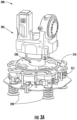
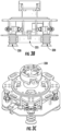
FIGS. 3a-3e illustrate different views of a robotic tool, in accordance with one or more embodiments of the present disclosure; -
FIG. 4 illustrates an exploded view of the robotic tool, in accordance with one or more embodiments of the present disclosure; -
FIGS. 14a and 14b illustrate perspective views of a vision system of the material handling system, in accordance with one or more embodiments of the present disclosure; -
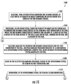
FIG. 15 illustrates a flow chart representing a method of manipulating an item by a material handling system, in accordance with various example embodiments described herein; -
FIG. 16 illustrates a flowchart representing another method of manipulating an item by a material handling system, in accordance with various example embodiments described herein;
and -
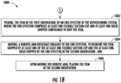
FIG. 18 illustrates a flowchart representing a method of reorienting the item from a first orientation to a second orientation, by another end effector, in accordance with some example embodiments described herein. - Some embodiments of the present invention will now be described more fully hereinafter with reference to the accompanying drawings, in which some, but not all embodiments of the inventions are shown. Indeed, the disclosure may be embodied in many different forms and should not be construed as limited to the embodiments set forth herein; rather, these embodiments are provided so that this disclosure will satisfy applicable legal requirements. The terms "or" and "optionally" are used herein in both the alternative and conjunctive sense, unless otherwise indicated. The terms "illustrative" and "exemplary" are used to be examples with no indication of quality level. Like numbers refer to like elements throughout.
- The components illustrated in the figures represent components that may or may not be present in various embodiments of the invention described herein such that embodiments may include fewer or more components than those shown in the figures while not departing from the scope of the invention.
- Turning now to the drawings, the detailed description set forth below in connection with the appended drawings is intended as a description of various configurations and is not intended to represent the only configurations in which the concepts described herein may be practiced. The detailed description includes specific details for the purpose of providing a thorough understanding of various concepts with like numerals denote like components throughout the several views. However, it will be apparent to those skilled in the art that these concepts may be practiced without these specific details.
- Typically, in a material handling environment having items with variable physical characteristics (e.g., length of the item, width of the item, height of the item, weight of the item, center of gravity of the item, body shape of the item, material strength of the item, and/or the like) the items are to be handled carefully by equipment, with a reliability so as to avoid any physical damage at a time of handling. Also, these items are handled by the equipment, such as, robotic tools and/or conveyors, at high speeds within the material handling environment. Accordingly, the robotic tools and/or other equipment within the material handling environment are required to operate at high speeds while still maintaining the reliability of handling the items and avoiding any mishandling which may cause a physical damage to the item during its manipulation.
- Various example embodiments described herein relate to a material handling system for manipulating items. Manipulating these items may be referred to hereinafter throughout the description as picking the items, gripping the items, re-positioning the items, retrieving the items, lifting the items, moving of the items, and/or reorienting the items from a first orientation to the second orientation, by equipment of the material handling system. In accordance with said example embodiments, the material handling system includes a repositioning system comprising a robotic tool. The robotic tool includes a robotic arm portion and an end effector coupled to the robotic arm portion. The robotic tool is configured to manipulate an item in a first orientation and reorient the item to a second orientation. According to various example embodiments described herein, different configurations of the end effector can be used in the repositioning system for manipulating the items.
- In another example embodiment, the end effector can be a vacuum gripper having one or more flexible suction cups and at least one rigid gripper for handling items of rigid or flexible body shapes. Other configurations of the end effector are also possible as illustrated and described hereafter.
- According to said example embodiments, the material handling system also includes, a vision system having one or more sensors positioned within the material handling system. The vision system is configured to generate inputs corresponding to one or more characteristics of the item. Some example characteristics of items that may be generated by the vision system may include a size of the item, position of the item, body shape of the item, orientation of the item, edges or markings on the item, presence of marker or a label on the item, and/or positioning of a label on the item.
- The material handling system also includes a controller. The controller is communicatively coupled to the repositioning system, the vision system, and/or other subsystems of the material handling system. The controller includes at least one processor configured to execute instructions to cause the material handling system to at least: identify by the vision system, the item in the first orientation, based on the one or more characteristics of the item generated by the vision system, initiate, by the repositioning system, picking of the item in the first orientation, and upon picking the item in the first orientation, reorient, by the repositioning system, the item to the second orientation.
- Having described example embodiments related to the present disclosure at a high level, the design of the various devices performing various example operations is provided below.
-
FIG. 1 andFIG. 2 illustrate a perspective view and a top view, respectively, of amaterial handling system 100, in accordance with one or more embodiments of the present disclosure. Thematerial handling system 100 may handle different types of items having varying physical characteristics. For example, thematerial handling system 100 can handle items (e.g., totes, containers, articles, shipment packages, boxes, envelops, paper bags, parcels, polybags, and/or the like) without limitation. Thematerial handling system 100 may include a variety of components and/or subsystems, such as an induction conveyor, sortation system, chutes, identification systems, vision systems, robotic subsystems, and/or the like, for handling and processing items. - According to various example embodiments described herein, the
material handling system 100 is configured to manipulate anitem 110 from a first orientation to a second orientation. In this regard, according to some example embodiments, arepositioning system 105 of thematerial handling system 100 is configured to receive theitem 110 in a first orientation from achute 125 and/or a conveyor (not shown). Therepositioning system 105 may further reorient theitem 110 from the first orientation to a second orientation for placement onto aconveyor 130 and/or any downstream subsystem of thematerial handling system 100. - As shown, the
material handling system 100 also includes avision system 115 comprising include one or more sensors such as cameras, photo detectors, proximity sensors, infra-red sensors, and/or the like. The one or more sensors of thevision system 115 may be positioned at various locations within thematerial handling system 100. In some example embodiments, the one or more sensors of thevision system 115 are configured to generate inputs corresponding to one or more characteristics of theitem 110. It should be noted that thevision system 115 is shown as a standalone camera inFIG. 1 ; however, thevision system 115 is not limited to the implementation shown inFIG. 1 . Thevision system 115 may include a network of imagers, sensors, cameras, identification systems, and/or the like, for determining characteristics of one or more items conveyed in thematerial handling system 100. The characteristics of theitem 110 may be utilized by one or more subsystems in the material handling environment such as, but not limited to, therepositioning system 105, thevision system 115, and/or other equipment within thematerial handling system 100. - The
material handling system 100 may further include, a control system (not shown) including a controller which may be communicably coupled with therepositioning system 105, thevision system 115, and/or other subsystems of thematerial handling system 100. In accordance with some example embodiments, the controller may include at least one processor that may execute instructions to cause thematerial handling system 100 to perform specific operations. In accordance with the embodiments of the present disclosure, the processor may execute instructions to cause the vision system to determine a first orientation of theitem 110 to be conveyed. The processor may further execute instructions to cause therepositioning system 105 to receive theitem 110 in the first orientation. Further, the processor may execute instructions to cause therepositioning system 105 to reorient theitem 110 to a second orientation for placement onto aconveyor 130, such as a downstream conveyor within thematerial handling system 100. In this regard, therepositioning system 105 may include a robotic end effector for manipulating theitem 110 including reorienting and repositioning of theitem 110. Details related to the end effector of therepositioning system 105 and its associated operations, are described later in reference toFIGS. 3-18 . - In accordance with an embodiment of the present disclosure, the
item 110, such as a parcel, may have a label placed thereon. As described herein, a label may also refer to a marker, imprinted information, encoded information marked on a surface, and/or the like. In some example embodiments, a label may correspond to a printed medium including an identifier which includes coded information, such as a barcode, QR code, 2D-code, 3D-code, Direct part marking (DPM) code, and/or the like. The label may include information corresponding to the item, such as, but not limited to, identifier for uniquely identifying a product within the item, a type of the item, a type of the product, a size of the product, product manufacturer's information, weight of the item, delivery address of the item, and/or the like. - According to some example embodiments, information corresponding to the
item 110 may be coded in an identifier, such as a barcode or a QR code, on the label associated with theitem 110. Accordingly, for handling and processing theitem 110, one or more subsystems of thematerial handling system 100 may scan the identifier on the label of theitem 110 at different stages of conveyance. During conveyance, an orientation of theitem 110 may change frequently. In some cases, theitem 110 may be orientated such that the label may not be positioned in view of a label identification system. The label identification system may correspond to a scanner configured to scan an identifier on the label. For example, the label identification may correspond to a barcode scanner, optical reader, an RFID reader, a bi-optic scanner, and/or the like configured for scanning an identifier associated with the label. - As described above, the
repositioning system 105 may reorient theitem 110 in a label-up position such that an identifier and/or the label associated with theitem 110 may be positioned on a top face of theitem 110 for scanning. According to some example embodiments, the controller may determine an orientation of the item. For instance, the controller may determine, via thevision system 115, a first orientation of theitem 110 in which a top surface of theitem 110 includes the label. In this case, in response to determining that the top surface of theitem 110 includes the label, the controller may instruct therepositioning system 105 and/or any other subsystem of thematerial handling system 100 to transfer theitem 110 to theconveyor 130 in the first orientation, that is, without reorienting theitem 110. Alternatively, the controller may determine, via thevision system 115, another orientation of theitem 110 in which the top surface of theitem 110 does not includes the label. In this regard, the controller may instruct therepositioning system 105 and/or any other subsystem of thematerial handling system 100 to transfer theitem 110 to theconveyor 130 in a second orientation different from the first orientation. In the second orientation, the label of the item would be positioned on the top surface of the item, such that, the identifier on the label is exposed in a field of view of the identification system, thereby facilitating scanning of the identifier. - In accordance with one or more embodiments of the present disclosure, the
repositioning system 105 may include a robotic tool having a robotic arm and an end effector. Therepositioning system 105 is configured to have different configurations of the end effector customized for manipulating items based on its one or more characteristics (e.g., body shape, type of the item, surface material of the item, and/or the like). The end effector of therepositioning system 105 includes a vacuum gripper for manipulating theitem 110. Different configurations of the end effectors of therepositioning system 105 are described hereinafter. -
FIGS. 3a to 3e illustrate different views of arobotic tool 300 of therepositioning system 105 of thematerial handling system 100, as shown inFIG. 1 andFIG. 2 , in accordance with an example embodiment. As shown, therobotic tool 300 may include arobotic arm portion 305 of a robotic arm (e.g., robotic arm 1235 illustrated in FIGS. 12a-12d) and anend effector 310 defined at an end thereof. The robotic arm may be any suitable robotic arm configured to provide sufficient degree of motion for picking, placing, repositioning, etc. an item and/or a group of items. According to some example embodiments, therobotic arm portion 305 is communicatively coupled to the control system that can control operations such as the movement, positioning, starting, and stopping, of therobotic arm portion 305. The control system of theitem manipulation system 102 may initiate movement of therobotic arm portion 305 so as to position theend effector 310 to any of a picking position, gripping position, retrieval position, and a discharging position of theitem 110, details of which are described hereafter. - In some alternate example embodiments, the
robotic tool 300 including therobotic arm portion 305 and theend effector 310 may be controlled by a controller remotely positioned and/or any other subsystem of thematerial handling system 100 to pick theitem 110 in a first orientation and reorient theitem 110 to a second orientation for placement onto theconveyor 130. - The
robotic arm portion 305, as shown inFIG. 3a , is rotatably attached to theend effector 310 through amount 330. Theend effector 310 may include any manipulator with a suitable gripping means, such as, but not limited to, vacuum, claw, finger, plate, and the like, for picking and handling theitem 110. - In accordance with an example embodiment of the present disclosure, the
end effector 310 may include avacuum gripper 315, as shown inFIGS. 3a-3e . Thevacuum gripper 315 may include one or moreflexible suction cups 320 and/or one or morerigid gripper 325. For instance, in some example embodiments, theend effector 310 may define at its one end, a configuration of thevacuum gripper 315 having four flexible suction cups, positioned at a respective corner defined by a bottom surface of thevacuum gripper 315 and one rigid gripper positioned at a center of the bottom surface of the vacuum gripper. In an alternate example embodiment, theend effector 310 may include another configuration of thevacuum gripper 315 having six flexible suction cups and two rigid grippers positioned on the bottom surface of thevacuum gripper 315. - Accordingly, in various example embodiments, the
end effector 310 may include different configurations ofvacuum gripper 315 having varying number of flexible suction cups and/or rigid grippers so as to engage items of different body shapes and different characteristics (e.g., weight, center of gravity, etc.). In this way, items are not mishandled or dropped during a movement of theend effector 106 and/or re-orientation of the items, as the items are handled. - According to various example embodiments described herein, the
robotic tool 300 may further include a vacuum source or a vacuum generator (not shown) for generating a vacuum suction force within the one or moreflexible suction cup 320 and the one or morerigid gripper 325. In operation, the vacuum generator may draw vacuum suction force through the respective one or moreflexible suction cups 320 and the one or morerigid gripper 325. For instance, in some example embodiments, the one or moreflexible suction cups 320 and the one or morerigid gripper 325 may engage a surface of theitem 110 based on a first vacuum suction force generated through theflexible suction cups 320 and/or a second vacuum suction force generated through the one or morerigid gripper 325. Each of theflexible suction cups 320 and the one or morerigid gripper 325 may be in fluidic communication with one or more vacuum generators (e.g., via a plenum or one or more vacuum rods (not shown)). In an example embodiment, the vacuum suction force drawn through the respective vacuum rods and through the respective one or moreflexible suction cups 320 and the one or morerigid gripper 325 may enable theend effector 310 to engage a surface of theitem 110 so as to manipulate theitem 110. - In some examples, the one or more
flexible suction cups 320 may be actuated by the controller to engage items having flexible body shape (e.g., parcels, polybags, paper bags, envelops and/or the like). In some examples, the one or morerigid gripper 325 may be actuated to grip items having rigid body shape (e.g., boxes, cartons, containers, totes, and/or the like). In some examples, both the one or moreflexible suction cups 320 and the one or morerigid gripper 325 may be actuated for engagement of theitem 110. Further, based on the body shape of theitem 110 handled by theitem manipulation system 102, varying amounts of suction forces may be generated through the respective one or moreflexible suction cups 320 and the one or morerigid gripper 325. - As described above, the
end effector 310 may be attached to therobotic arm portion 305 through amount 330 such that theend effector 310 may be capable of rotating with respect to therobotic arm portion 305. For rotating anitem 110, thevacuum gripper 315 may contact theitem 110 in a first orientation. As described above, based on the position, size, and/or weight of theitem 110, a vacuum suction force may be created in one or more of theflexible suction cups 320 and/or the one or morerigid gripper 325 for picking theitem 110 in the first orientation. - In one or more example embodiments of the present disclosure, the
robotic tool 300 may further include one or more sensors (e.g., a force sensor, a torque sensor, and/or a distance sensor) configured to measure characteristics of the item 110 (e.g., weight, position, orientation, center of gravity, size, etc.). Thus, the position, size, and/or weight of theitem 110 may be determined by therobotic tool 300 or any other subsystem of thematerial handling system 100. - Further, in some example embodiments, the control system and/or any other subsystem of the
material handling system 100 may determine, via thevision system 115, that theitem 110 is to be manipulated from the first orientation to a second orientation. For example, the control system may determine a need of reorienting theitem 110 before placing theitem 110 onto a downstream conveyor and/or section of thematerial handling system 100. As an example, a label and/or a marker placed on theitem 110 may be positioned upside down, theitem 110 may have a longer edge that may jam in the downstream conveyor, or theitem 110 may need to be oriented in a specific orientation to fit a palletizing pattern. Upon determining that theitem 110 needs to be reoriented, theend effector 106 may be controlled to rotate about themount 330 in order to change the position and/or the orientation of theitem 110. In some embodiments, theend effector 106 may be rotated in a clockwise direction to rotate theitem 110 within a range from about 0 degrees to about 180 degrees to align a label placed on theitem 110 for scanning. Further, once theitem 110 is reoriented, therobotic arm portion 305 may be moved to position theend effector 106 at a position so as to place theitem 110 on theconveyor 130. - The
vacuum gripper 315 of theend effector 310 also includes one or more ejectors that may be actuated for respective flexible suction cups 362 and/or the one or more rigid gripper 364 for releasing theitem 110 onto theconveyor 130 in the second orientation. Accordingly, once theitem 110 is reoriented, therobotic tool 300 may place theitem 110 on theconveyor 130 and may activate one or more ejectors for respective one or moreflexible suction cups 320 and/or the one or morerigid gripper 325 for releasing theitem 110 onto theconveyor 130 in the second orientation. In an embodiment, the ejector may receive compressed air fed into the one or moreflexible suction cups 320 and the one or morerigid gripper 325. It should be noted that therobotic tool 300 may reorient theitem 110 in-hand while holding theitem 110, or may reorient theitem 110 in one or more steps while picking and/or placing theitem 110. -
FIG. 4 illustrates an exploded view of therobotic tool 300, in accordance with an embodiment of the present disclosure. Therobotic tool 300 includes arobotic arm portion 305 attached to arobot flange adapter 405. Therobot flange adapter 405 may include and/or be attached to at least onesensor 410 mounted on asensor mounting flange 415. In an embodiment, the at least onesensor 410 may include a plurality of sensors (e.g., force sensor, torque sensor, distance sensor, and/or the like) to measure different characteristics of theitem 110. In an embodiment, the at least onesensor 410 may determine a weight distribution and/or center of gravity of theitem 110 and generate sensor data. Based on processing the sensor data generated by the at least onesensor 410, the control system may cause the vacuum generators to control generation of the vacuum suction force through each of the one or moreflexible suction cups 320 and/or the one or morerigid gripper 325. Thesensor mounting flange 415 is further attached to thevacuum gripper 315. Thevacuum gripper 315 includes adust plate 425 at the bottom of thevacuum gripper 315, as shown inFIG. 4 . - In an embodiment, the
robotic tool 300 further includes alaser range finder 430, as shown inFIG. 4 . As shown, thelaser range finder 430 is disposed on a distal end of theend effector 310. Thelaser range finder 430 is configured to identify (e.g., periodically or continuously over a period of time), theitem 110 positioned in the first orientation. Thelaser range finder 430 is also configured to determine a distance at which theitem 110 is positioned with relative to thevacuum gripper 315. For example, in some embodiments, thelaser range finder 430 may determine the distance between a top surface of theitem 110 and an end of the vacuum gripper 315 (e.g., between the one or moreflexible suction cups 320 and the one or more rigid gripper 325). Based on the determined distance, the controller may cause therobotic arm portion 305 to position theend effector 310 into different operating positions. For instance, in some example embodiments, based on the determined distance communicated to the controller, theend effector 310 may be moved into at least one of: the picking position to pick theitem 110 in the first orientation, the gripping position in which the one or moreflexible suction cups 320 and/or the one or morerigid gripper 325 can be selectively actuated to grip theitem 110, the retrieval position in which theend effector 310 is moved to retrieve theitem 110 from amongst multiple items on a conveyor, and the discharging position, in which theend effector 310 is moved to place theitem 110 in the second orientation by ejecting theitem 110 engaged to theend effector 310 based on ejectors of respective of the one or moreflexible suction cups 320 and/or the one or morerigid gripper 325. In accordance with some example embodiments herein, thelaser range finder 430 may include a light source configured to emit a laser beam or light rays, and trace a time of flight of the emitted light to contact theitem 110 and return to the laser range finder 430 (e.g., reflection). -
FIGS. 14a and 14b illustrate a vision and control subsystem of thematerial handling system 100, in accordance with one or more embodiments of the present disclosure. An identification of theitem 110 and its orientation, (e.g., a label up orientation), may be performed by a sensing system comprising one or more sensors. For example, in some example embodiments, avision system 1400 may include the one or more sensors including a camera and/or multiple cameras (not shown) installed around an area in a material handling environment having theitem 110 which is be handled by therepositioning system 105. In this regard, in some example embodiments, the one or more cameras of thevision system 1400, may feed image data to the controller, and the controller may analyze the images at a high rate to identify a position of theitem 110, an orientation of the item, and/or a label placed on theitem 110. In addition, the cameras and/or the controller may also assess physical characteristics associated with the item, (e.g., a size, weight, and/or the like) of theitem 110. The one or more sensors of thevision system 1400 may also include, e.g., a laser sensor, force sensor, torque sensor, and/or the like, to monitor such physical characteristics of theitem 110. Thevision system 1400 and/or the controller may also make an initial assessment of the physical characteristics of theitem 110 to select an item handling procedure based on which theend effector 310 of therepositioning system 105, handles theitem 110. For example, in some cases, the controller may perform the initial assessment to determine at least one of a type of theitem 110, body shape of the item, orientation of theitem 110, and/or the like. For instance, in some cases, the controller may determine theitem 110 to be a bag, a box, a tote, a polybag, an envelope, and/or the like. The initial assessment may be performed based on colleting sensor and/or image data, before picking the item and/or at the time of picking theitem 110, and further throughout an item handling process. - Further, the
vision system 1400 and/or the controller may classify theitem 110 based on utilizing machine learning classification. In this regard, the sensor data and/or the images collected by the controller may be used as a training set to generate a trainable model for automatically classifying theitem 110 and selecting an item handling procedure for theend effector 310 based on the classification of theitem 110. The selection of the item handling procedure can be done, prior to picking of theitem 110 by theend effector 310. In some cases, in order to adjust a picking strategy and enabling theend effector 310 to react to pick theitem 110 by using feedback from one or more sensors, such as, a force, torque, and/or vacuum sensor, to make real time assessment of how to best handle motions of one or more subsystems of thematerial handling system 100 to successfully handle theitem 110. Further, labels and/or other identifiers associated with theitem 110 may be scanned while theitem 110 is picked and/or is in motion. -
FIGS. 15 ,16 , and18 illustrates example flowcharts of operations performed by a material handling system for manipulating an item, in accordance with example embodiments of the present invention. It will be understood that each block of the flowcharts, and combinations of blocks in the flowcharts, may be implemented by various means, such as hardware, firmware, one or more processors, circuitry and/or other devices associated with execution of software including one or more computer program instructions. For example, one or more of the procedures described above may be embodied by computer program instructions. In this regard, the computer program instructions which embody the procedures described above may be stored by a memory of an apparatus employing an embodiment of the present invention and executed by a processor in the apparatus. As will be appreciated, any such computer program instructions may be loaded onto a computer or other programmable apparatus (e.g., hardware) to produce a machine, such that the resulting computer or other programmable apparatus provides for implementation of the functions specified in the flowcharts' block(s). These computer program instructions may also be stored in a non-transitory computer-readable storage memory that may direct a computer or other programmable apparatus to function in a particular manner, such that the instructions stored in the computer-readable storage memory produce an item of manufacture, the execution of which implements the function specified in the flowcharts' block(s). The computer program instructions may also be loaded onto a computer or other programmable apparatus to cause a series of operations to be performed on the computer or other programmable apparatus to produce a computer-implemented process such that the instructions which execute on the computer or other programmable apparatus provide operations for implementing the functions specified in the flowcharts' block(s). As such, the operations ofFIGS. 15 ,16 , &18 when executed, convert a computer or processing circuitry into a particular machine configured to perform an example embodiment of the present invention. Accordingly, the operations ofFIGS. 15 ,16 , &18 define an algorithm for configuring a computer or processor, to perform an example embodiment. In some cases, a general purpose computer may be provided with an instance of the processor which performs the algorithm ofFIGS. 15 ,16 , &18 to transform the general purpose computer into a particular machine configured to perform an example embodiment. - Accordingly, blocks of the flowcharts support combinations of means for performing the specified functions and combinations of operations for performing the specified functions. It will also be understood that one or more blocks of the flowcharts, and combinations of blocks in the flowchart, can be implemented by special purpose hardware-based computer systems which perform the specified functions, or combinations of special purpose hardware and computer instructions.
-
FIG. 15 illustrates a flowchart describing amethod 1500 for manipulating an item, by thematerial handling system 100, from a first orientation to a second orientation in a material handling environment. According to some example embodiments, atstep 1502, thematerial handling system 100 may include means such as, the vision system (115, 1400) and/or theend effector 310, comprising one or more sensors from which at least one of a plurality of images comprising theitem 110 or sensor data sensed by the one or more sensors, may be accessed by the controller. In this regard, in some examples, the one or more sensors may include, a force sensor, a torque sensor, a distance sensor, photo diodes, barcode scanners, RFID readers, and/or the like. - At
step 1504, the controller of the material handling system may, via the vision system (115, 1400) process, either the plurality of images or the sensor data, to generate one or more characteristics of the item and a first orientation of theitem 110. In some examples, the one or more characteristics comprise at least one of physical characteristics of theitem 110, for example, a size of theitem 110, body shape of theitem 110, texture of theitem 110, features like, edges, blobs on body of theitem 110, surfaces of theitem 110, label of theitem 110, orientation of the label of theitem 110, location of the label of theitem 110, type of theitem 110, identifier on the label of theitem 110, distance of theitem 110 from theend effector 310, and/or the like. - Moving to step 1506, the controller of the
material handling system 100 may select an item handling procedure indicative of a configuration of therobotic tool 300, based on which theend effector 310 of therepositioning system 105 manipulates the item. In this regard, the controller may select the item handling procedure based on the identified one or more characteristics and the first orientation of the item, atstep 1504. It may be understood that procedures for handling different items by robotic tools in a material handling system may vary depending on different physical characteristics of respective items. For instance, depending on a product type, in an example, theend effector 310 may be configured to manipulate theitem 110 based on a first item handling procedure for grasping an item which is a hard-sided box. Similarly, in another example, theend effector 310 may be configured to manipulate theitem 110 based on a second item handling procedure for grasping the item which is a flexible and squishy polybag. In some cases, an item handling procedure for which theend effector 310 is pre-configured may be adjusted based on the identified one or more characteristics of theitem 110. - Based on the selected item handling procedure, at
step 1508, thematerial handling system 100 may include therepositioning system 105 comprising the robotic tool to pick, by theend effector 310, the item in the first orientation. In this regard, theitem 110 may be picked based on engagement of theitem 110 with theend effector 310 using any suitable configurations of theend effector 310, as described earlier, in various embodiments related toFIGS. 3a-14b . - At
step 1510, thematerial handling system 100 may include means such as the end effector of therepositioning system 105 to reorient the item in a second orientation. In this regard, theitem 110 may be reoriented based on any of: flipping of theitem 110 or rotating of theitem 110 etc., via any configuration of theend effector 310 as described earlier, in various embodiments related toFIGS. 3a-14b . -
FIG. 16 illustrates another flowchart describing anothermethod 1600 for manipulating an item from a first orientation to a second orientation in a material handling environment by thematerial handling system 100, as described in reference toFIG. 1 . In this regard, in some cases, it is required to operate theend effector 310 so as to, pick an item from a first conveyor, reorient the item, and place the item to either the first conveyor or a second conveyor. In accordance with some example embodiments, upon generating the one or more characteristics of theitem 110, as described atstep 1504 ofFIG. 15 , atstep 1602, thematerial handling system 100 may include means such as, the vision system (115, 1400) to determine the first orientation of theitem 110 to be conveyed on a conveyor such as, theconveyor 130. In this regard, atstep 1604, the vision system (115, 1400) may determine if in the first orientation of theitem 110, a top surface of theitem 110 includes a label. Here, the top surface of the item refers to a surface of the item which is exposed to a field of view of one or more sensors of the vision system (115, 1400). In response to determining that the top surface of theitem 110 includes the label, the method moves to step 1606, where the controller of thematerial handling system 100, may transfer the item to theconveyor 130 in the first orientation. - Otherwise, at
step 1604, in response to determining that the top surface of theitem 110 does not include the label, the method moves to step 1608, where the controller of thematerial handling system 100, may initiate, via the repositionsystem 105, reorientation of the item from the first orientation to the second orientation. Here, the second orientation the top surface of the item includes the label. To this extent, the reorientation of theitem 110 may be performed using any configuration of theend effector 310 of therobotic tool 300 of therepositioning system 105, based on as described earlier, in various embodiments related toFIGS. 3a-14b . Thus, the controller of thematerial handling system 100 causes to manipulate theitem 110, via therobotic tool 300, from the first orientation to the second orientation for cases, where theitem 110 includes a label which is not positioned on a top surface exposed in a field of view of the vision system (115, 1400). Otherwise, theitem 110 is conveyed as such, without any handling by therobotic tool 300 for reorienting theitem 110. -
FIG. 18 illustrates another flowchart representing amethod 1800 of repositioning theitem 110 from a first orientation to a second orientation, by another end effector, in accordance with some example embodiments. In this regard, the end effector comprises thevacuum gripper 315 having the one or moreflexible suction cups 320 and/or the one or morerigid gripper 325, as described earlier in reference toFIGS. 3a-3e . - In accordance with some example embodiments, upon picking the
item 110 in the first orientation by therepositioning system 105, as described atstep 1508 ofFIG. 15 . For reorienting the item in the second orientation, themethod 1800, atstep 1802 includes, picking, by the end effector of therepositioning system 105, theitem 110 in the first orientation. In this regard, the controller may selectively actuate one or more of theflexible suction cups 320 and/or the one or morerigid gripper 325 of theend effector 310 to cause engage of theitem 110 with thevacuum gripper 315. For instance, in an example case, if theitem 110 is of a flexible body shape such as, but not limited to, an envelope, a poly bag, a paper bag package and/or the like, the controller may actuate the one or moreflexible suction cups 320 to grip theitem 110 by vacuum suction force generated through the one or moreflexible suction cups 320. Accordingly, in another example case, if theitem 110 is of a rigid body shape such as, but not limited to, a tote, a container, a heavy box, carton, and/or the like, the controller may actuate the one or morerigid gripper 325 to grip theitem 110 by vacuum suction force generated through therigid gripper 325. - The method further includes, at
step 1804, moving, therobotic arm portion 305 rotatably engaged to theend effector 310, to reorient theitem 110 gripped by at least one of the one or moreflexible suction cups 320 and/or the one or morerigid gripper 325 of the end effector, in the second orientation. In this regard, theend effector 310 may be rotated to change the orientation of theitem 110 engaged to thevacuum gripper 315. - Further, upon moving the robotic arm, the
method 1800, atstep 1806 includes, placing, by theend effector 310 of therepositioning system 105, theitem 110 in the second orientation. In this regard, upon placement of theitem 110, one or more ejectors of theend effector 310 may eject theitem 110 engaged with thevacuum gripper 315. - It must be noted that, as used in this specification and the appended claims, the singular forms "a," "an" and "the" include plural referents unless the content clearly dictates otherwise.
- References within the specification to "one embodiment," "an embodiment," "embodiments", or "one or more embodiments" are intended to indicate that a particular feature, structure, or characteristic described in connection with the embodiment is included in at least one embodiment of the present disclosure. The appearance of such phrases in various places within the specification are not necessarily all referring to the same embodiment, nor are separate or alternative embodiments mutually exclusive of other embodiments. Further, various features are described which may be exhibited by some embodiments and not by others. Similarly, various requirements are described which may be requirements for some embodiments but not other embodiments.
- It should be noted that, when employed in the present disclosure, the terms "comprises," "comprising," and other derivatives from the root term "comprise" are intended to be open-ended terms that specify the presence of any stated features, elements, integers, steps, or components, and are not intended to preclude the presence or addition of one or more other features, elements, integers, steps, components, or groups thereof.
- As required, detailed embodiments of the present invention are disclosed herein; however, it is to be understood that the disclosed embodiments are merely exemplary of the invention, which may be embodied in various forms. Therefore, specific structural and functional details disclosed herein are not to be interpreted as limiting, but merely as a basis for the claims and as a representative basis for teaching one skilled in the art to variously employ the present invention in virtually any appropriately detailed structure.
- While it is apparent that the illustrative embodiments of the invention herein disclosed fulfill the objectives stated above, it will be appreciated that numerous modifications and other embodiments may be devised by one of ordinary skill in the art. Accordingly, it will be understood that the appended claims are intended to cover all such modifications and embodiments, which come within the scope of the appended claims.
Claims (5)
- A material handling system (100) for manipulating items, the material handling system comprising:a repositioning system (105) comprising:
a robotic tool (300), wherein the robotic tool comprises:a robotic arm portion (305), andan end effector (310), coupled to the robotic arm portion,and comprising a vacuum gripper (315) rotatably engaged to the robotic arm, wherein the vacuum gripper comprises at least one flexible suction cup and at least one rigid gripper cup adapted to grip an item and rotate about an axis to manipulate the item from a first orientation to a second orientation;a vision system (115), comprising one or more sensors positioned within the material handling system, wherein the vision system is configured to generate inputs corresponding to one or more characteristics of the item; anda controller communicatively coupled to the repositioning system and the vision system, wherein the controller comprises at least one processor configured to execute instructions to cause the material handling system to:identify, by the vision system, the item in the first orientation, including determining the first orientation of the item being conveyed on a conveyor;based on the one or more characteristics of the item generated by the vision system, initiate, by the repositioning system, receiving of the item in the first orientation;determine if in the first orientation of the item, a top surface of the item includes a label, marker, or barcode;in response to determining that the top surface of the item includes the label, marker, or barcode, transfer the item to the conveyor in the first orientation; andin response to determining that the top surface of the item does not include the label, marker, or barcode, initiate, via the repositioning system, reorientation of the item to the second orientation, wherein in the second orientation the top surface of the item includes the label, marker, or barcode, and transferring the item to the conveyor in the second orientation. - The material handling system (100) of claim 1, wherein the controller is further configured to:access, from the vision system (115), at least one of:a plurality of images captured by at least a camera of the vision system, wherein the plurality of images comprise the item, orsensor data collected from the one or more sensors;process, via the vision system, either the plurality of images or the sensor data to generate the one or more characteristics of the item (110), wherein the one or more characteristics comprise one or more of: a shape of the item, a weight of the item, an edge of the item, a label on the item, a marker on the item, or a category of the item;classify the item based on the one or more characteristics of the item; andbased on the classification, select, an item handling procedure indicative of a configuration of the repositioning system based on which the repositioning system (105) manipulates the item.
- The material handling system (100) of claim 1, wherein the robotic tool (300) further comprises one or more sensors, wherein the one or more sensors include at least one of a force sensor, a torque sensor, or a distance sensor.
- The material handling system (100) of claim 1, wherein the repositioning system (105) is configured to receive the item (110) from a chute or a conveyor in the first orientation, wherein the chute or the conveyor is configured to receive the item from an upstream conveyor of the material handling system.
- The material handling system (100) of claim 1, wherein the item (110) is positioned in the first orientation on a conveyor, wherein the conveyor is:a section of the material handling system positioned downstream from the repositioning system; oran induction conveyor for a sortation system of the material handling system.
Priority Applications (1)
| Application Number | Priority Date | Filing Date | Title |
|---|---|---|---|
| EP25177586.2A EP4599998A3 (en) | 2018-05-09 | 2019-05-08 | Method and system for manipulating items |
Applications Claiming Priority (2)
| Application Number | Priority Date | Filing Date | Title |
|---|---|---|---|
| US201862669093P | 2018-05-09 | 2018-05-09 | |
| US16/405,060 US11318620B2 (en) | 2018-05-09 | 2019-05-07 | Method and system for manipulating items |
Related Child Applications (2)
| Application Number | Title | Priority Date | Filing Date |
|---|---|---|---|
| EP25177586.2A Division EP4599998A3 (en) | 2018-05-09 | 2019-05-08 | Method and system for manipulating items |
| EP25177586.2A Division-Into EP4599998A3 (en) | 2018-05-09 | 2019-05-08 | Method and system for manipulating items |
Publications (3)
| Publication Number | Publication Date |
|---|---|
| EP3575043A2 EP3575043A2 (en) | 2019-12-04 |
| EP3575043A3 EP3575043A3 (en) | 2020-03-25 |
| EP3575043B1 true EP3575043B1 (en) | 2025-07-02 |
Family
ID=66476419
Family Applications (2)
| Application Number | Title | Priority Date | Filing Date |
|---|---|---|---|
| EP25177586.2A Pending EP4599998A3 (en) | 2018-05-09 | 2019-05-08 | Method and system for manipulating items |
| EP19173384.9A Active EP3575043B1 (en) | 2018-05-09 | 2019-05-08 | Method and system for manipulating items |
Family Applications Before (1)
| Application Number | Title | Priority Date | Filing Date |
|---|---|---|---|
| EP25177586.2A Pending EP4599998A3 (en) | 2018-05-09 | 2019-05-08 | Method and system for manipulating items |
Country Status (2)
| Country | Link |
|---|---|
| US (1) | US11318620B2 (en) |
| EP (2) | EP4599998A3 (en) |
Families Citing this family (34)
| Publication number | Priority date | Publication date | Assignee | Title |
|---|---|---|---|---|
| US10262404B2 (en) * | 2016-06-14 | 2019-04-16 | General Electric Company | Method and system for articulation of a visual inspection device |
| WO2019143710A1 (en) | 2018-01-17 | 2019-07-25 | Berkshire Grey, Inc. | Systems and methods for efficiently moving a variety of objects |
| US11458635B2 (en) | 2018-05-09 | 2022-10-04 | Intelligrated Headquarters, Llc | Method and system for manipulating articles |
| US11318620B2 (en) * | 2018-05-09 | 2022-05-03 | Intelligrated Headquarters, Llc | Method and system for manipulating items |
| TWI787529B (en) * | 2018-07-16 | 2022-12-21 | 開曼群島商星猿哲科技國際有限公司 | Robotic system for picking, sorting, and placing a plurality of random and novel objects |
| CN113396035A (en) | 2019-02-27 | 2021-09-14 | 伯克希尔格雷股份有限公司 | System and method for hose wiring in programmable motion systems |
| EP3959050B1 (en) | 2019-04-25 | 2024-04-17 | Berkshire Grey Operating Company, Inc. | System and method for maintaining vacuum hose life in hose routing systems in programmable motion systems |
| US11007654B2 (en) * | 2019-06-21 | 2021-05-18 | Intelligrated Headquarters, Llc | End manipulator for package picking and placing |
| US11701776B2 (en) * | 2019-10-25 | 2023-07-18 | Dexterity, Inc. | Robotic kitting machine |
| US11534927B2 (en) | 2019-12-30 | 2022-12-27 | Intelligrated Headquarters, Llc | Object gripping mechanism |
| CN111543257B (en) * | 2020-05-09 | 2022-01-28 | 吉林大学 | Mushroom is picked with anti-damage bionic sucking disc with detect function |
| CA3199771A1 (en) * | 2020-10-29 | 2022-05-05 | Berkshire Grey Operating Company, Inc. | Systems and methods for automated packaging and processing for shipping with object pose analysis |
| CN116669911A (en) * | 2020-10-29 | 2023-08-29 | 伯克希尔格雷营业股份有限公司 | System and method for automated packaging and handling by container alignment for shipment |
| JP2022090523A (en) * | 2020-12-07 | 2022-06-17 | 東急建設株式会社 | Robot hand, robot arm, and control system |
| US20220193918A1 (en) * | 2020-12-21 | 2022-06-23 | All Weigh Automation LLC | Robotically manipulated container gripper and related systems and methods |
| CN112881413B (en) * | 2021-02-02 | 2023-04-07 | 苏州威达智科技股份有限公司 | Appearance detection line suitable for porcelain plate |
| EP4304818A4 (en) * | 2021-03-10 | 2025-03-19 | Aquabot Ltd. | System and method for identifying or capturing data corresponding to a wearable article |
| JP7574702B2 (en) * | 2021-03-11 | 2024-10-29 | 日本電気株式会社 | GRIP DEVICE AND METHOD FOR CONTROLLING GRIP DEVICE |
| DE102021108906A1 (en) * | 2021-04-09 | 2022-10-13 | Linde Material Handling Gmbh | Mobile picking robot |
| US12421054B2 (en) | 2021-04-16 | 2025-09-23 | Mujin, Inc. | Robotic multi-surface gripper assemblies and methods for operating the same |
| JP7725246B2 (en) | 2021-06-04 | 2025-08-19 | 株式会社東芝 | Handling system, transport system, control device, program, and handling method |
| US20230055386A1 (en) * | 2021-08-20 | 2023-02-23 | Titan Medical Inc. | Robotic surgery system |
| US12558799B2 (en) | 2021-12-15 | 2026-02-24 | The Boeing Company | Gripping apparatus and associated systems and methods for gripping flexible materials |
| AT526215B1 (en) * | 2022-06-08 | 2025-06-15 | Tgw Logistics Group Gmbh | Transfer device and method for handling packing units |
| EP4299258A1 (en) * | 2022-06-23 | 2024-01-03 | Fameccanica.Data S.p.A. | A gripping device and apparatus for handling products |
| WO2024019945A1 (en) * | 2022-07-18 | 2024-01-25 | Dexterity, Inc. | Robotic gripper with support structure |
| CN115256440B (en) * | 2022-08-30 | 2025-03-21 | 山东东都汽车部件股份有限公司 | End picker and end picker suction cup for industrial robot |
| US12318941B2 (en) * | 2022-09-28 | 2025-06-03 | International Business Machines Corporation | Material movement track to assist robotic arm |
| WO2024122475A1 (en) * | 2022-12-07 | 2024-06-13 | ソフトバンクグループ株式会社 | Control system for robot and control program for robot |
| TWI844200B (en) | 2022-12-13 | 2024-06-01 | 財團法人工業技術研究院 | System and method for automatically storing stirrup |
| JP2026508948A (en) * | 2023-03-13 | 2026-03-13 | シャンハイ・フレクシブ・ロボティクス・テクノロジー・カンパニー・リミテッド | Adhesion device, end effector, and robot |
| WO2025079183A1 (en) * | 2023-10-11 | 2025-04-17 | ファナック株式会社 | Robot hand and robot |
| WO2025144622A1 (en) * | 2023-12-27 | 2025-07-03 | Assurant, Inc. | Robot enabled mobile device manipulation system, method, and apparatus |
| DE102024130539A1 (en) * | 2024-10-21 | 2026-04-23 | IGZ Ingenieurgesellschaft für logistische Informationssysteme mbH | Picking robot with labeling device |
Citations (1)
| Publication number | Priority date | Publication date | Assignee | Title |
|---|---|---|---|---|
| US4697689A (en) * | 1985-12-26 | 1987-10-06 | Rca Corporation | Article manipulation system |
Family Cites Families (88)
| Publication number | Priority date | Publication date | Assignee | Title |
|---|---|---|---|---|
| DE2357118A1 (en) | 1973-11-15 | 1975-05-28 | Matthias Dipl Ing Kiwull | Tilting table for moving large panes of glass - esp. insulating panes used for double glazing |
| US4390390A (en) * | 1981-04-30 | 1983-06-28 | Hobart Corporation | Label applicator device |
| US4613942A (en) | 1982-02-19 | 1986-09-23 | Chen Richard M | Orientation and control system for robots |
| EP0134843B1 (en) | 1983-09-02 | 1987-10-28 | Agfa-Gevaert N.V. | Photographic exposure apparatus including a means for the relative positioning of a photographic material and an original in sheet form |
| US4571320A (en) | 1984-10-31 | 1986-02-18 | General Motors Corporation | Method and apparatus for loading and unloading sheet molding compound in and from a press |
| US4634328A (en) | 1985-05-31 | 1987-01-06 | Rca Corporation | Mail singulation system |
| US4741567A (en) | 1987-01-12 | 1988-05-03 | Rca Corporation | Robotic system and end effector |
| US4987332A (en) | 1988-09-30 | 1991-01-22 | Pentel Kabushiki Kaisha | Robot hand for electrostatically applying thin workpiece to mold |
| FI92170C (en) | 1993-02-09 | 1994-10-10 | Valmet Paper Machinery Inc | Grab to grip the end tags |
| US5908283A (en) | 1996-11-26 | 1999-06-01 | United Parcel Service Of Americia, Inc. | Method and apparatus for palletizing packages of random size and weight |
| AU772459C (en) | 1998-03-24 | 2005-02-24 | Metrologic Instruments, Inc. | Automated system and method for identifying and measuring packages transported through a laser scanning tunnel |
| US6015174A (en) | 1998-06-04 | 2000-01-18 | Eastman Kodak Company | Universal end effector for robotic applications |
| JP3900229B2 (en) | 1998-06-25 | 2007-04-04 | 石川島播磨重工業株式会社 | Board transfer hand |
| US6857844B2 (en) | 1999-07-19 | 2005-02-22 | The Goodyear Tire & Rubber Company | Method and apparatus for removing tire treads from storage device |
| US6517130B1 (en) | 2000-03-14 | 2003-02-11 | Applied Materials, Inc. | Self positioning vacuum chuck |
| US6833901B2 (en) * | 2002-02-27 | 2004-12-21 | Lg. Philips Lcd Co., Ltd. | Method for fabricating LCD having upper substrate coated with sealant |
| US7153454B2 (en) | 2003-01-21 | 2006-12-26 | University Of Southern California | Multi-nozzle assembly for extrusion of wall |
| WO2005008726A2 (en) * | 2003-07-09 | 2005-01-27 | Newport Corporation | Flip chip device assembly machine |
| US6923309B2 (en) | 2003-10-03 | 2005-08-02 | Laitram, L.L.C. | Article-orienting conveyor |
| US7131372B2 (en) | 2003-12-01 | 2006-11-07 | Lockheed Martin Corporation | Miniature fluid dispensing end-effector for geometrically constrained areas |
| US20080314324A1 (en) | 2004-03-30 | 2008-12-25 | Delaval Holding Ab | Arrangement and Method for Determining Positions of the Teats of a Milking Animal |
| US7175017B2 (en) | 2004-06-22 | 2007-02-13 | Lockheed Martin Corporation | In-line flipper mechanism and conveyor system for achieving the proper orientation of mail tray and mail tub receptacles |
| US7648322B2 (en) | 2005-12-27 | 2010-01-19 | Graphic Packaging International, Inc. | Automatic carton magazine loading system |
| ITMO20060054A1 (en) | 2006-02-16 | 2007-08-17 | Aetna Group S P A Dimac Division | APPARATUS FOR ORIENTING ITEMS |
| EP2027045A2 (en) | 2006-06-15 | 2009-02-25 | Laitram, L.L.C. | Article-rotating belt conveyor |
| US7313464B1 (en) | 2006-09-05 | 2007-12-25 | Adept Technology Inc. | Bin-picking system for randomly positioned objects |
| US8167530B2 (en) | 2007-07-25 | 2012-05-01 | Pearson Packaging Systems | Robotic pallet-emptying and magazine-loading apparatus |
| DE102007052012A1 (en) | 2007-10-31 | 2009-05-07 | Grenzebach Maschinenbau Gmbh | Method and device for detecting and reloading luggage |
| DE102007054867A1 (en) | 2007-11-07 | 2009-05-20 | J. Schmalz Gmbh | Workpiece i.e. cup, gripping device, has rolling module and suction module engaged at workpiece at same time or one after other, where suction module is formed from surface suction gripper |
| JP4708464B2 (en) | 2008-09-30 | 2011-06-22 | ファナック株式会社 | Work gripping device |
| US7941990B2 (en) | 2009-01-06 | 2011-05-17 | Pi-Wi Beheer B.V. | Apparatus for packaging products into a container |
| JP2010188465A (en) | 2009-02-18 | 2010-09-02 | Kanto Auto Works Ltd | Robot hand |
| WO2010109923A1 (en) | 2009-03-27 | 2010-09-30 | シャープ株式会社 | Transfer device, transfer hand, and transfer method |
| JP2010278408A (en) | 2009-04-30 | 2010-12-09 | Fluoro Mechanic Kk | Bernoulli chuck |
| NL1037512C2 (en) | 2009-11-30 | 2011-05-31 | Vanderlande Ind Bv | DEVICE FOR GRIPPING OBJECTS. |
| US20120205928A1 (en) | 2011-02-11 | 2012-08-16 | Stefano La Rovere | Gripper Assembly for Mechanical Device |
| JP2012223860A (en) | 2011-04-20 | 2012-11-15 | Murata Machinery Ltd | Suction chuck, and transfer device of workpiece including same |
| US9265227B2 (en) | 2011-04-28 | 2016-02-23 | Technologies Holdings Corp. | System and method for improved attachment of a cup to a dairy animal |
| JP5472214B2 (en) | 2011-06-20 | 2014-04-16 | 株式会社安川電機 | Picking system |
| US9129277B2 (en) * | 2011-08-30 | 2015-09-08 | Digimarc Corporation | Methods and arrangements for identifying objects |
| DE102012009649B4 (en) | 2012-05-14 | 2016-05-12 | Fraunhofer-Gesellschaft zur Förderung der angewandten Forschung e.V. | gripping device |
| DE102012013022A1 (en) | 2012-06-29 | 2014-04-24 | Liebherr-Verzahntechnik Gmbh | Device for the automated handling of workpieces |
| US20140126988A1 (en) | 2012-11-02 | 2014-05-08 | Shenzhen China Star Optoelectronics Technology Co. Ltd. | Transportation System For Moving Flat Panel And Mechanical Apparatus Thereof And Method For Moving The Same |
| CN203064744U (en) | 2012-12-04 | 2013-07-17 | 富鼎电子科技(嘉善)有限公司 | Turnover device |
| FR3000915B1 (en) | 2013-01-17 | 2015-03-13 | Amg Ind | GRIPPING DEVICE AND ASSOCIATED METHOD |
| US9393686B1 (en) | 2013-03-15 | 2016-07-19 | Industrial Perception, Inc. | Moveable apparatuses having robotic manipulators and conveyors to facilitate object movement |
| KR20160058917A (en) * | 2013-09-20 | 2016-05-25 | 어플라이드 머티어리얼스, 인코포레이티드 | Substrate carrier with integrated electrostatic chuck |
| JP5996566B2 (en) | 2014-02-12 | 2016-09-21 | 信越エンジニアリング株式会社 | Work chuck device, work laminating machine, and work laminating method |
| US9802728B1 (en) * | 2014-03-26 | 2017-10-31 | Amazon Technologies, Inc. | Rotatable tamp head and automated dimension determination |
| JP6305213B2 (en) | 2014-05-29 | 2018-04-04 | 株式会社東芝 | Extraction device and method |
| US9498887B1 (en) | 2014-07-24 | 2016-11-22 | X Development Llc | Two-faced linearly actuated gripper |
| WO2016054561A1 (en) | 2014-10-03 | 2016-04-07 | Frito-Lay North America, Inc. | Apparatus and method for pattern creation |
| CN106999987B (en) | 2014-10-29 | 2019-08-02 | 菲韦斯内部物流单一股东股份公司 | Device for feeding items to a sorter, sorter and method thereof |
| CN104360507B (en) | 2014-11-17 | 2018-01-30 | 合肥京东方光电科技有限公司 | Turning device, substrate are to box system and substrate to cassette method |
| US9561587B2 (en) | 2014-12-16 | 2017-02-07 | Amazon Technologies, Inc. | Robotic grasping of items in inventory system |
| FR3031048B1 (en) | 2014-12-24 | 2016-12-30 | Solystic | POSTAL SORTING MACHINE WITH FEED INPUT COMPRISING A ROBOTIC ARM AND A FLAT CONVEYOR |
| FR3031046B1 (en) | 2014-12-24 | 2018-06-29 | Solystic | INSTALLATION FOR THE SEPARATION AND INDIVIDUALIZATION OF HETEROGENEOUS POSTAL OBJECTS |
| US9574883B2 (en) * | 2015-03-24 | 2017-02-21 | X Development Llc | Associating semantic location data with automated environment mapping |
| US9911640B2 (en) | 2015-09-01 | 2018-03-06 | Boris Kesil | Universal gripping and suction chuck |
| US10137566B2 (en) * | 2015-09-09 | 2018-11-27 | Bastian Solutions, Llc | Automated guided vehicle (AGV) with batch picking robotic arm |
| CN204954848U (en) | 2015-09-17 | 2016-01-13 | 广州市泰立机电设备有限公司 | Two -sided sucking disc anchor clamps |
| US9926138B1 (en) * | 2015-09-29 | 2018-03-27 | Amazon Technologies, Inc. | Determination of removal strategies |
| MX391518B (en) | 2015-12-16 | 2025-03-19 | Comau Llc | Adaptable end effector and method |
| WO2017111348A1 (en) * | 2015-12-21 | 2017-06-29 | (주)제이티 | Flip device handler |
| JP6622598B2 (en) | 2016-01-14 | 2019-12-18 | 株式会社アマダホールディングス | Robot hand, articulated robot, and material loading method |
| JP7097071B2 (en) | 2016-01-20 | 2022-07-07 | ソフト ロボティクス, インコーポレイテッド | Soft robot grippers for scattered gripping environments, high-acceleration movement, food manipulation, and automated storage and recovery systems |
| CA3178174A1 (en) * | 2016-02-08 | 2017-08-17 | Berkshire Grey Operating Company, Inc. | Systems and methods for providing processing of a variety of objects employing motion planning |
| JP6741222B2 (en) | 2016-03-23 | 2020-08-19 | 日産自動車株式会社 | Robot work transfer method and work transfer device |
| WO2017198281A1 (en) * | 2016-05-17 | 2017-11-23 | Liebherr-Verzahntechnik Gmbh | Order-picking cell |
| FR3051452B1 (en) * | 2016-05-17 | 2018-06-01 | Irelec | HANDLING AND STORAGE FACILITY OF VERY LOW TEMPERATURE BIOLOGICAL SAMPLES |
| JP6283058B2 (en) | 2016-05-18 | 2018-02-21 | アマゾン テクノロジーズ インコーポレイテッド | System and method for automatic picking of products in material handling facilities |
| US9981382B1 (en) * | 2016-06-03 | 2018-05-29 | X Development Llc | Support stand to reorient the grasp of an object by a robot |
| US10221015B2 (en) | 2016-06-27 | 2019-03-05 | Amazon Technologies, Inc. | Automated item singulation |
| JP6474365B2 (en) | 2016-07-22 | 2019-02-27 | ファナック株式会社 | Palletizing system for loading items on pallets |
| US9704126B1 (en) | 2016-08-22 | 2017-07-11 | Amazon Technologies, Inc. | Inventory handling by anisotropically adhesive gripping |
| CN206484792U (en) * | 2017-02-07 | 2017-09-12 | 上海天檀电子科技有限公司 | Insert injection moulding automatic detection device |
| US20180264660A1 (en) | 2017-03-20 | 2018-09-20 | Kindred Systems Inc. | Systems, devices, articles, and methods for prehension |
| US11396076B2 (en) * | 2017-04-19 | 2022-07-26 | Christopher E. Baker | Modular automated table-top production pod |
| CN207273223U (en) | 2017-08-21 | 2018-04-27 | 浙江新瑞铭装饰材料有限公司 | A kind of plate detects turning manipulator |
| US10668630B2 (en) | 2017-08-22 | 2020-06-02 | Emerging Acquisitions, Llc | High speed manipulation of non-uniform ojects |
| CN107444909B (en) | 2017-08-30 | 2023-05-12 | 江西衡源智能装备股份有限公司 | Automatic processing device for large-size workpiece |
| US11007648B2 (en) | 2017-09-05 | 2021-05-18 | Abb Schweiz Ag | Robotic system for grasping objects |
| CN107745963A (en) | 2017-09-20 | 2018-03-02 | 广东长盈精密技术有限公司 | Take-and-discharge mechanism and take-and-discharge device |
| US10902377B2 (en) | 2018-01-24 | 2021-01-26 | Amazon Technologies, Inc. | Robotic item handling using a variable area manipulator |
| US11318620B2 (en) * | 2018-05-09 | 2022-05-03 | Intelligrated Headquarters, Llc | Method and system for manipulating items |
| US12083670B2 (en) | 2020-04-01 | 2024-09-10 | Ambi Robotics, Inc. | End effector device and system for suction-based grasping of bagged objects |
| CA3189612A1 (en) | 2020-07-22 | 2022-01-27 | Berkshire Grey Operating Company, Inc. | Systems and methods for object processing using a vacuum gripper that provides object retention by evacuation |
| CA3189565A1 (en) | 2020-07-22 | 2022-01-27 | Berkshire Grey Operating Company, Inc. | Systems and methods for object processing using a passively collapsing vacuum gripper |
-
2019
- 2019-05-07 US US16/405,060 patent/US11318620B2/en active Active
- 2019-05-08 EP EP25177586.2A patent/EP4599998A3/en active Pending
- 2019-05-08 EP EP19173384.9A patent/EP3575043B1/en active Active
Patent Citations (1)
| Publication number | Priority date | Publication date | Assignee | Title |
|---|---|---|---|---|
| US4697689A (en) * | 1985-12-26 | 1987-10-06 | Rca Corporation | Article manipulation system |
Also Published As
| Publication number | Publication date |
|---|---|
| EP3575043A3 (en) | 2020-03-25 |
| EP4599998A3 (en) | 2025-11-12 |
| US20190344447A1 (en) | 2019-11-14 |
| EP3575043A2 (en) | 2019-12-04 |
| US11318620B2 (en) | 2022-05-03 |
| EP4599998A2 (en) | 2025-08-13 |
Similar Documents
| Publication | Publication Date | Title |
|---|---|---|
| US11318620B2 (en) | Method and system for manipulating items | |
| US11458635B2 (en) | Method and system for manipulating articles | |
| US10822177B2 (en) | Method and system for manipulating articles | |
| CN112166013B (en) | Robotic system for picking, sorting and placing multiple random and novel items | |
| US12472647B2 (en) | Method and system for manipulating articles | |
| US11724394B2 (en) | Systems and methods for providing processing of a variety of objects employing motion planning | |
| US12427546B2 (en) | System and method for robotic horizontal sortation | |
| KR20220165262A (en) | Pick and Place Robot System | |
| KR102492117B1 (en) | Control device and method for item verification | |
| CN113460559B (en) | System and method for processing objects comprising an automatically moving matrix carrier | |
| CN110740954B (en) | Systems and methods for handling objects including space efficient dispensing stations and automated output handling | |
| CN114148666B (en) | System and method for processing objects including an automated linear processing station | |
| CN110199231B (en) | Systems and methods for handling objects | |
| CN110662707A (en) | System and method for processing objects including automatically moving matrix boxes | |
| CN110691742A (en) | System and method for processing objects including automated processing | |
| CN108349083A (en) | Sorting system and method for providing sorting of various objects | |
| EP4304818A1 (en) | System and method for identifying or acquiring data corresponding to a handled item | |
| WO2026101407A1 (en) | Methods and systems for handling stock keeping units | |
| WO2026101406A1 (en) | Methods and systems for handling stock keeping units | |
| WO2025071419A1 (en) | Methods and systems for robotic item picking ports for automated warehouses |
Legal Events
| Date | Code | Title | Description |
|---|---|---|---|
| PUAI | Public reference made under article 153(3) epc to a published international application that has entered the european phase |
Free format text: ORIGINAL CODE: 0009012 |
|
| STAA | Information on the status of an ep patent application or granted ep patent |
Free format text: STATUS: REQUEST FOR EXAMINATION WAS MADE |
|
| 17P | Request for examination filed |
Effective date: 20190508 |
|
| AK | Designated contracting states |
Kind code of ref document: A2 Designated state(s): AL AT BE BG CH CY CZ DE DK EE ES FI FR GB GR HR HU IE IS IT LI LT LU LV MC MK MT NL NO PL PT RO RS SE SI SK SM TR |
|
| AX | Request for extension of the european patent |
Extension state: BA ME |
|
| PUAL | Search report despatched |
Free format text: ORIGINAL CODE: 0009013 |
|
| AK | Designated contracting states |
Kind code of ref document: A3 Designated state(s): AL AT BE BG CH CY CZ DE DK EE ES FI FR GB GR HR HU IE IS IT LI LT LU LV MC MK MT NL NO PL PT RO RS SE SI SK SM TR |
|
| AX | Request for extension of the european patent |
Extension state: BA ME |
|
| RIC1 | Information provided on ipc code assigned before grant |
Ipc: B25J 13/08 20060101ALI20200217BHEP Ipc: G05B 19/418 20060101ALI20200217BHEP Ipc: B25J 9/16 20060101AFI20200217BHEP Ipc: B25J 15/06 20060101ALI20200217BHEP Ipc: B25J 15/00 20060101ALI20200217BHEP |
|
| STAA | Information on the status of an ep patent application or granted ep patent |
Free format text: STATUS: EXAMINATION IS IN PROGRESS |
|
| 17Q | First examination report despatched |
Effective date: 20210924 |
|
| GRAP | Despatch of communication of intention to grant a patent |
Free format text: ORIGINAL CODE: EPIDOSNIGR1 |
|
| STAA | Information on the status of an ep patent application or granted ep patent |
Free format text: STATUS: GRANT OF PATENT IS INTENDED |
|
| INTG | Intention to grant announced |
Effective date: 20250122 |
|
| GRAS | Grant fee paid |
Free format text: ORIGINAL CODE: EPIDOSNIGR3 |
|
| GRAA | (expected) grant |
Free format text: ORIGINAL CODE: 0009210 |
|
| STAA | Information on the status of an ep patent application or granted ep patent |
Free format text: STATUS: THE PATENT HAS BEEN GRANTED |
|
| AK | Designated contracting states |
Kind code of ref document: B1 Designated state(s): AL AT BE BG CH CY CZ DE DK EE ES FI FR GB GR HR HU IE IS IT LI LT LU LV MC MK MT NL NO PL PT RO RS SE SI SK SM TR |
|
| REG | Reference to a national code |
Ref country code: GB Ref legal event code: FG4D |
|
| REG | Reference to a national code |
Ref country code: CH Ref legal event code: EP |
|
| REG | Reference to a national code |
Ref country code: DE Ref legal event code: R096 Ref document number: 602019071853 Country of ref document: DE |
|
| REG | Reference to a national code |
Ref country code: IE Ref legal event code: FG4D |
|
| REG | Reference to a national code |
Ref country code: NL Ref legal event code: MP Effective date: 20250702 |
|
| PG25 | Lapsed in a contracting state [announced via postgrant information from national office to epo] |
Ref country code: PT Free format text: LAPSE BECAUSE OF FAILURE TO SUBMIT A TRANSLATION OF THE DESCRIPTION OR TO PAY THE FEE WITHIN THE PRESCRIBED TIME-LIMIT Effective date: 20251103 |
|
| PG25 | Lapsed in a contracting state [announced via postgrant information from national office to epo] |
Ref country code: NL Free format text: LAPSE BECAUSE OF FAILURE TO SUBMIT A TRANSLATION OF THE DESCRIPTION OR TO PAY THE FEE WITHIN THE PRESCRIBED TIME-LIMIT Effective date: 20250702 |
|
| REG | Reference to a national code |
Ref country code: AT Ref legal event code: MK05 Ref document number: 1808737 Country of ref document: AT Kind code of ref document: T Effective date: 20250702 |
|
| PG25 | Lapsed in a contracting state [announced via postgrant information from national office to epo] |
Ref country code: IS Free format text: LAPSE BECAUSE OF FAILURE TO SUBMIT A TRANSLATION OF THE DESCRIPTION OR TO PAY THE FEE WITHIN THE PRESCRIBED TIME-LIMIT Effective date: 20251102 |
|
| PG25 | Lapsed in a contracting state [announced via postgrant information from national office to epo] |
Ref country code: NO Free format text: LAPSE BECAUSE OF FAILURE TO SUBMIT A TRANSLATION OF THE DESCRIPTION OR TO PAY THE FEE WITHIN THE PRESCRIBED TIME-LIMIT Effective date: 20251002 |
|
| REG | Reference to a national code |
Ref country code: LT Ref legal event code: MG9D |
|
| PG25 | Lapsed in a contracting state [announced via postgrant information from national office to epo] |
Ref country code: AT Free format text: LAPSE BECAUSE OF FAILURE TO SUBMIT A TRANSLATION OF THE DESCRIPTION OR TO PAY THE FEE WITHIN THE PRESCRIBED TIME-LIMIT Effective date: 20250702 |
|
| PG25 | Lapsed in a contracting state [announced via postgrant information from national office to epo] |
Ref country code: FI Free format text: LAPSE BECAUSE OF FAILURE TO SUBMIT A TRANSLATION OF THE DESCRIPTION OR TO PAY THE FEE WITHIN THE PRESCRIBED TIME-LIMIT Effective date: 20250702 |
|
| PG25 | Lapsed in a contracting state [announced via postgrant information from national office to epo] |
Ref country code: HR Free format text: LAPSE BECAUSE OF FAILURE TO SUBMIT A TRANSLATION OF THE DESCRIPTION OR TO PAY THE FEE WITHIN THE PRESCRIBED TIME-LIMIT Effective date: 20250702 |
|
| PG25 | Lapsed in a contracting state [announced via postgrant information from national office to epo] |
Ref country code: GR Free format text: LAPSE BECAUSE OF FAILURE TO SUBMIT A TRANSLATION OF THE DESCRIPTION OR TO PAY THE FEE WITHIN THE PRESCRIBED TIME-LIMIT Effective date: 20251003 |
|
| PG25 | Lapsed in a contracting state [announced via postgrant information from national office to epo] |
Ref country code: SE Free format text: LAPSE BECAUSE OF FAILURE TO SUBMIT A TRANSLATION OF THE DESCRIPTION OR TO PAY THE FEE WITHIN THE PRESCRIBED TIME-LIMIT Effective date: 20250702 Ref country code: CZ Free format text: LAPSE BECAUSE OF FAILURE TO SUBMIT A TRANSLATION OF THE DESCRIPTION OR TO PAY THE FEE WITHIN THE PRESCRIBED TIME-LIMIT Effective date: 20250702 |
|
| PG25 | Lapsed in a contracting state [announced via postgrant information from national office to epo] |
Ref country code: LV Free format text: LAPSE BECAUSE OF FAILURE TO SUBMIT A TRANSLATION OF THE DESCRIPTION OR TO PAY THE FEE WITHIN THE PRESCRIBED TIME-LIMIT Effective date: 20250702 |
|
| PG25 | Lapsed in a contracting state [announced via postgrant information from national office to epo] |
Ref country code: BG Free format text: LAPSE BECAUSE OF FAILURE TO SUBMIT A TRANSLATION OF THE DESCRIPTION OR TO PAY THE FEE WITHIN THE PRESCRIBED TIME-LIMIT Effective date: 20250702 Ref country code: PL Free format text: LAPSE BECAUSE OF FAILURE TO SUBMIT A TRANSLATION OF THE DESCRIPTION OR TO PAY THE FEE WITHIN THE PRESCRIBED TIME-LIMIT Effective date: 20250702 |
|
| PG25 | Lapsed in a contracting state [announced via postgrant information from national office to epo] |
Ref country code: RS Free format text: LAPSE BECAUSE OF FAILURE TO SUBMIT A TRANSLATION OF THE DESCRIPTION OR TO PAY THE FEE WITHIN THE PRESCRIBED TIME-LIMIT Effective date: 20251002 |
|
| PG25 | Lapsed in a contracting state [announced via postgrant information from national office to epo] |
Ref country code: ES Free format text: LAPSE BECAUSE OF FAILURE TO SUBMIT A TRANSLATION OF THE DESCRIPTION OR TO PAY THE FEE WITHIN THE PRESCRIBED TIME-LIMIT Effective date: 20250702 |
|
| PG25 | Lapsed in a contracting state [announced via postgrant information from national office to epo] |
Ref country code: SM Free format text: LAPSE BECAUSE OF FAILURE TO SUBMIT A TRANSLATION OF THE DESCRIPTION OR TO PAY THE FEE WITHIN THE PRESCRIBED TIME-LIMIT Effective date: 20250702 |
|
| PG25 | Lapsed in a contracting state [announced via postgrant information from national office to epo] |
Ref country code: DK Free format text: LAPSE BECAUSE OF FAILURE TO SUBMIT A TRANSLATION OF THE DESCRIPTION OR TO PAY THE FEE WITHIN THE PRESCRIBED TIME-LIMIT Effective date: 20250702 |
|
| PG25 | Lapsed in a contracting state [announced via postgrant information from national office to epo] |
Ref country code: IT Free format text: LAPSE BECAUSE OF FAILURE TO SUBMIT A TRANSLATION OF THE DESCRIPTION OR TO PAY THE FEE WITHIN THE PRESCRIBED TIME-LIMIT Effective date: 20250702 |
|
| PG25 | Lapsed in a contracting state [announced via postgrant information from national office to epo] |
Ref country code: EE Free format text: LAPSE BECAUSE OF FAILURE TO SUBMIT A TRANSLATION OF THE DESCRIPTION OR TO PAY THE FEE WITHIN THE PRESCRIBED TIME-LIMIT Effective date: 20250702 Ref country code: SK Free format text: LAPSE BECAUSE OF FAILURE TO SUBMIT A TRANSLATION OF THE DESCRIPTION OR TO PAY THE FEE WITHIN THE PRESCRIBED TIME-LIMIT Effective date: 20250702 |
|
| PLBE | No opposition filed within time limit |
Free format text: ORIGINAL CODE: 0009261 |
|
| STAA | Information on the status of an ep patent application or granted ep patent |
Free format text: STATUS: NO OPPOSITION FILED WITHIN TIME LIMIT |