EP3574927A2 - Portable telemedicine system with integrated medical imaging and uv sterilization - Google Patents
Portable telemedicine system with integrated medical imaging and uv sterilization Download PDFInfo
- Publication number
- EP3574927A2 EP3574927A2 EP19157934.1A EP19157934A EP3574927A2 EP 3574927 A2 EP3574927 A2 EP 3574927A2 EP 19157934 A EP19157934 A EP 19157934A EP 3574927 A2 EP3574927 A2 EP 3574927A2
- Authority
- EP
- European Patent Office
- Prior art keywords
- console
- portable medical
- user input
- compartment
- remote
- Prior art date
- Legal status (The legal status is an assumption and is not a legal conclusion. Google has not performed a legal analysis and makes no representation as to the accuracy of the status listed.)
- Withdrawn
Links
Images


Classifications
-
- A—HUMAN NECESSITIES
- A61—MEDICAL OR VETERINARY SCIENCE; HYGIENE
- A61L—METHODS OR APPARATUS FOR STERILISING MATERIALS OR OBJECTS IN GENERAL; DISINFECTION, STERILISATION OR DEODORISATION OF AIR; CHEMICAL ASPECTS OF BANDAGES, DRESSINGS, ABSORBENT PADS OR SURGICAL ARTICLES; MATERIALS FOR BANDAGES, DRESSINGS, ABSORBENT PADS OR SURGICAL ARTICLES
- A61L2/00—Disinfection or sterilisation of materials or objects, in general; Accessories therefor
- A61L2/02—Disinfection or sterilisation of materials or objects, in general; Accessories therefor using physical processes
- A61L2/08—Radiation
- A61L2/10—Ultraviolet [UV] radiation
-
- A—HUMAN NECESSITIES
- A61—MEDICAL OR VETERINARY SCIENCE; HYGIENE
- A61B—DIAGNOSIS; SURGERY; IDENTIFICATION
- A61B18/00—Surgical instruments, devices or methods for transferring non-mechanical forms of energy to or from the body
- A61B18/04—Surgical instruments, devices or methods for transferring non-mechanical forms of energy to or from the body by heating
- A61B18/12—Surgical instruments, devices or methods for transferring non-mechanical forms of energy to or from the body by heating by passing a current through the tissue to be heated, e.g. high-frequency current
- A61B18/14—Probes or electrodes therefor
- A61B18/1442—Probes having pivoting end effectors, e.g. forceps
- A61B18/1445—Probes having pivoting end effectors, e.g. forceps at the distal end of a shaft, e.g. forceps or scissors at the end of a rigid rod
- A61B18/1447—Probes having pivoting end effectors, e.g. forceps at the distal end of a shaft, e.g. forceps or scissors at the end of a rigid rod wherein sliding surfaces cause opening/closing of the end effectors
-
- A—HUMAN NECESSITIES
- A61—MEDICAL OR VETERINARY SCIENCE; HYGIENE
- A61B—DIAGNOSIS; SURGERY; IDENTIFICATION
- A61B18/00—Surgical instruments, devices or methods for transferring non-mechanical forms of energy to or from the body
- A61B18/18—Surgical instruments, devices or methods for transferring non-mechanical forms of energy to or from the body by applying electromagnetic radiation, e.g. microwaves
- A61B18/1815—Surgical instruments, devices or methods for transferring non-mechanical forms of energy to or from the body by applying electromagnetic radiation, e.g. microwaves using microwaves
-
- A—HUMAN NECESSITIES
- A61—MEDICAL OR VETERINARY SCIENCE; HYGIENE
- A61B—DIAGNOSIS; SURGERY; IDENTIFICATION
- A61B90/00—Instruments, implements or accessories specially adapted for surgery or diagnosis and not covered by any of the groups A61B1/00 - A61B50/00, e.g. for luxation treatment or for protecting wound edges
- A61B90/36—Image-producing devices or illumination devices not otherwise provided for
- A61B90/37—Surgical systems with images on a monitor during operation
-
- A—HUMAN NECESSITIES
- A61—MEDICAL OR VETERINARY SCIENCE; HYGIENE
- A61B—DIAGNOSIS; SURGERY; IDENTIFICATION
- A61B90/00—Instruments, implements or accessories specially adapted for surgery or diagnosis and not covered by any of the groups A61B1/00 - A61B50/00, e.g. for luxation treatment or for protecting wound edges
- A61B90/40—Apparatus fixed or close to patients specially adapted for providing an aseptic surgical environment
-
- A—HUMAN NECESSITIES
- A61—MEDICAL OR VETERINARY SCIENCE; HYGIENE
- A61G—TRANSPORT, PERSONAL CONVEYANCES, OR ACCOMMODATION SPECIALLY ADAPTED FOR PATIENTS OR DISABLED PERSONS; OPERATING TABLES OR CHAIRS; CHAIRS FOR DENTISTRY; FUNERAL DEVICES
- A61G12/00—Accommodation for nursing, e.g. in hospitals, not covered by groups A61G1/00 - A61G11/00, e.g. trolleys for transport of medicaments or food; Prescription lists
- A61G12/002—Supply appliances, e.g. columns for gas, fluid, electricity supply
- A61G12/005—Supply appliances, e.g. columns for gas, fluid, electricity supply mounted on the wall
-
- A—HUMAN NECESSITIES
- A61—MEDICAL OR VETERINARY SCIENCE; HYGIENE
- A61G—TRANSPORT, PERSONAL CONVEYANCES, OR ACCOMMODATION SPECIALLY ADAPTED FOR PATIENTS OR DISABLED PERSONS; OPERATING TABLES OR CHAIRS; CHAIRS FOR DENTISTRY; FUNERAL DEVICES
- A61G13/00—Operating tables; Auxiliary appliances therefor
- A61G13/0036—Orthopaedic operating tables
-
- A—HUMAN NECESSITIES
- A61—MEDICAL OR VETERINARY SCIENCE; HYGIENE
- A61G—TRANSPORT, PERSONAL CONVEYANCES, OR ACCOMMODATION SPECIALLY ADAPTED FOR PATIENTS OR DISABLED PERSONS; OPERATING TABLES OR CHAIRS; CHAIRS FOR DENTISTRY; FUNERAL DEVICES
- A61G13/00—Operating tables; Auxiliary appliances therefor
- A61G13/10—Parts, details or accessories
- A61G13/107—Supply appliances
-
- A—HUMAN NECESSITIES
- A61—MEDICAL OR VETERINARY SCIENCE; HYGIENE
- A61G—TRANSPORT, PERSONAL CONVEYANCES, OR ACCOMMODATION SPECIALLY ADAPTED FOR PATIENTS OR DISABLED PERSONS; OPERATING TABLES OR CHAIRS; CHAIRS FOR DENTISTRY; FUNERAL DEVICES
- A61G13/00—Operating tables; Auxiliary appliances therefor
- A61G13/10—Parts, details or accessories
- A61G13/108—Means providing sterile air at a surgical operation table or area
-
- A—HUMAN NECESSITIES
- A61—MEDICAL OR VETERINARY SCIENCE; HYGIENE
- A61L—METHODS OR APPARATUS FOR STERILISING MATERIALS OR OBJECTS IN GENERAL; DISINFECTION, STERILISATION OR DEODORISATION OF AIR; CHEMICAL ASPECTS OF BANDAGES, DRESSINGS, ABSORBENT PADS OR SURGICAL ARTICLES; MATERIALS FOR BANDAGES, DRESSINGS, ABSORBENT PADS OR SURGICAL ARTICLES
- A61L2/00—Disinfection or sterilisation of materials or objects, in general; Accessories therefor
- A61L2/02—Disinfection or sterilisation of materials or objects, in general; Accessories therefor using physical processes
- A61L2/04—Heat
- A61L2/06—Hot gas
-
- A—HUMAN NECESSITIES
- A61—MEDICAL OR VETERINARY SCIENCE; HYGIENE
- A61L—METHODS OR APPARATUS FOR STERILISING MATERIALS OR OBJECTS IN GENERAL; DISINFECTION, STERILISATION OR DEODORISATION OF AIR; CHEMICAL ASPECTS OF BANDAGES, DRESSINGS, ABSORBENT PADS OR SURGICAL ARTICLES; MATERIALS FOR BANDAGES, DRESSINGS, ABSORBENT PADS OR SURGICAL ARTICLES
- A61L2/00—Disinfection or sterilisation of materials or objects, in general; Accessories therefor
- A61L2/02—Disinfection or sterilisation of materials or objects, in general; Accessories therefor using physical processes
- A61L2/14—Plasma, i.e. ionised gases
-
- A—HUMAN NECESSITIES
- A61—MEDICAL OR VETERINARY SCIENCE; HYGIENE
- A61L—METHODS OR APPARATUS FOR STERILISING MATERIALS OR OBJECTS IN GENERAL; DISINFECTION, STERILISATION OR DEODORISATION OF AIR; CHEMICAL ASPECTS OF BANDAGES, DRESSINGS, ABSORBENT PADS OR SURGICAL ARTICLES; MATERIALS FOR BANDAGES, DRESSINGS, ABSORBENT PADS OR SURGICAL ARTICLES
- A61L2/00—Disinfection or sterilisation of materials or objects, in general; Accessories therefor
- A61L2/16—Disinfection or sterilisation of materials or objects, in general; Accessories therefor using chemical substances
- A61L2/20—Gaseous substances, e.g. vapours
-
- A—HUMAN NECESSITIES
- A61—MEDICAL OR VETERINARY SCIENCE; HYGIENE
- A61N—ELECTROTHERAPY; MAGNETOTHERAPY; RADIATION THERAPY; ULTRASOUND THERAPY
- A61N1/00—Electrotherapy; Circuits therefor
- A61N1/18—Applying electric currents by contact electrodes
- A61N1/32—Applying electric currents by contact electrodes alternating or intermittent currents
- A61N1/36—Applying electric currents by contact electrodes alternating or intermittent currents for stimulation
- A61N1/372—Arrangements in connection with the implantation of stimulators
- A61N1/37211—Means for communicating with stimulators
- A61N1/37235—Aspects of the external programmer
- A61N1/37247—User interfaces, e.g. input or presentation means
-
- A—HUMAN NECESSITIES
- A61—MEDICAL OR VETERINARY SCIENCE; HYGIENE
- A61N—ELECTROTHERAPY; MAGNETOTHERAPY; RADIATION THERAPY; ULTRASOUND THERAPY
- A61N1/00—Electrotherapy; Circuits therefor
- A61N1/18—Applying electric currents by contact electrodes
- A61N1/32—Applying electric currents by contact electrodes alternating or intermittent currents
- A61N1/36—Applying electric currents by contact electrodes alternating or intermittent currents for stimulation
- A61N1/372—Arrangements in connection with the implantation of stimulators
- A61N1/37211—Means for communicating with stimulators
- A61N1/37252—Details of algorithms or data aspects of communication system, e.g. handshaking, transmitting specific data or segmenting data
- A61N1/37264—Changing the program; Upgrading firmware
-
- A—HUMAN NECESSITIES
- A61—MEDICAL OR VETERINARY SCIENCE; HYGIENE
- A61N—ELECTROTHERAPY; MAGNETOTHERAPY; RADIATION THERAPY; ULTRASOUND THERAPY
- A61N1/00—Electrotherapy; Circuits therefor
- A61N1/18—Applying electric currents by contact electrodes
- A61N1/32—Applying electric currents by contact electrodes alternating or intermittent currents
- A61N1/36—Applying electric currents by contact electrodes alternating or intermittent currents for stimulation
- A61N1/372—Arrangements in connection with the implantation of stimulators
- A61N1/37211—Means for communicating with stimulators
- A61N1/37252—Details of algorithms or data aspects of communication system, e.g. handshaking, transmitting specific data or segmenting data
- A61N1/37282—Details of algorithms or data aspects of communication system, e.g. handshaking, transmitting specific data or segmenting data characterised by communication with experts in remote locations using a network
-
- G—PHYSICS
- G16—INFORMATION AND COMMUNICATION TECHNOLOGY [ICT] SPECIALLY ADAPTED FOR SPECIFIC APPLICATION FIELDS
- G16H—HEALTHCARE INFORMATICS, i.e. INFORMATION AND COMMUNICATION TECHNOLOGY [ICT] SPECIALLY ADAPTED FOR THE HANDLING OR PROCESSING OF MEDICAL OR HEALTHCARE DATA
- G16H20/00—ICT specially adapted for therapies or health-improving plans, e.g. for handling prescriptions, for steering therapy or for monitoring patient compliance
- G16H20/40—ICT specially adapted for therapies or health-improving plans, e.g. for handling prescriptions, for steering therapy or for monitoring patient compliance relating to mechanical, radiation or invasive therapies, e.g. surgery, laser therapy, dialysis or acupuncture
-
- G—PHYSICS
- G16—INFORMATION AND COMMUNICATION TECHNOLOGY [ICT] SPECIALLY ADAPTED FOR SPECIFIC APPLICATION FIELDS
- G16H—HEALTHCARE INFORMATICS, i.e. INFORMATION AND COMMUNICATION TECHNOLOGY [ICT] SPECIALLY ADAPTED FOR THE HANDLING OR PROCESSING OF MEDICAL OR HEALTHCARE DATA
- G16H30/00—ICT specially adapted for the handling or processing of medical images
- G16H30/20—ICT specially adapted for the handling or processing of medical images for handling medical images, e.g. DICOM, HL7 or PACS
-
- G—PHYSICS
- G16—INFORMATION AND COMMUNICATION TECHNOLOGY [ICT] SPECIALLY ADAPTED FOR SPECIFIC APPLICATION FIELDS
- G16H—HEALTHCARE INFORMATICS, i.e. INFORMATION AND COMMUNICATION TECHNOLOGY [ICT] SPECIALLY ADAPTED FOR THE HANDLING OR PROCESSING OF MEDICAL OR HEALTHCARE DATA
- G16H40/00—ICT specially adapted for the management or administration of healthcare resources or facilities; ICT specially adapted for the management or operation of medical equipment or devices
- G16H40/60—ICT specially adapted for the management or administration of healthcare resources or facilities; ICT specially adapted for the management or operation of medical equipment or devices for the operation of medical equipment or devices
- G16H40/67—ICT specially adapted for the management or administration of healthcare resources or facilities; ICT specially adapted for the management or operation of medical equipment or devices for the operation of medical equipment or devices for remote operation
-
- G—PHYSICS
- G16—INFORMATION AND COMMUNICATION TECHNOLOGY [ICT] SPECIALLY ADAPTED FOR SPECIFIC APPLICATION FIELDS
- G16H—HEALTHCARE INFORMATICS, i.e. INFORMATION AND COMMUNICATION TECHNOLOGY [ICT] SPECIALLY ADAPTED FOR THE HANDLING OR PROCESSING OF MEDICAL OR HEALTHCARE DATA
- G16H80/00—ICT specially adapted for facilitating communication between medical practitioners or patients, e.g. for collaborative diagnosis, therapy or health monitoring
-
- A—HUMAN NECESSITIES
- A61—MEDICAL OR VETERINARY SCIENCE; HYGIENE
- A61B—DIAGNOSIS; SURGERY; IDENTIFICATION
- A61B17/00—Surgical instruments, devices or methods
- A61B17/28—Surgical forceps
- A61B17/285—Surgical forceps combined with cutting implements
-
- A—HUMAN NECESSITIES
- A61—MEDICAL OR VETERINARY SCIENCE; HYGIENE
- A61B—DIAGNOSIS; SURGERY; IDENTIFICATION
- A61B18/00—Surgical instruments, devices or methods for transferring non-mechanical forms of energy to or from the body
- A61B18/04—Surgical instruments, devices or methods for transferring non-mechanical forms of energy to or from the body by heating
- A61B18/12—Surgical instruments, devices or methods for transferring non-mechanical forms of energy to or from the body by heating by passing a current through the tissue to be heated, e.g. high-frequency current
- A61B18/1206—Generators therefor
-
- A—HUMAN NECESSITIES
- A61—MEDICAL OR VETERINARY SCIENCE; HYGIENE
- A61B—DIAGNOSIS; SURGERY; IDENTIFICATION
- A61B17/00—Surgical instruments, devices or methods
- A61B2017/00017—Electrical control of surgical instruments
- A61B2017/00212—Electrical control of surgical instruments using remote controls
-
- A—HUMAN NECESSITIES
- A61—MEDICAL OR VETERINARY SCIENCE; HYGIENE
- A61B—DIAGNOSIS; SURGERY; IDENTIFICATION
- A61B17/00—Surgical instruments, devices or methods
- A61B2017/00017—Electrical control of surgical instruments
- A61B2017/00221—Electrical control of surgical instruments with wireless transmission of data, e.g. by infrared radiation or radiowaves
-
- A—HUMAN NECESSITIES
- A61—MEDICAL OR VETERINARY SCIENCE; HYGIENE
- A61B—DIAGNOSIS; SURGERY; IDENTIFICATION
- A61B17/00—Surgical instruments, devices or methods
- A61B2017/00017—Electrical control of surgical instruments
- A61B2017/00225—Systems for controlling multiple different instruments, e.g. microsurgical systems
-
- A—HUMAN NECESSITIES
- A61—MEDICAL OR VETERINARY SCIENCE; HYGIENE
- A61B—DIAGNOSIS; SURGERY; IDENTIFICATION
- A61B18/00—Surgical instruments, devices or methods for transferring non-mechanical forms of energy to or from the body
- A61B2018/00571—Surgical instruments, devices or methods for transferring non-mechanical forms of energy to or from the body for achieving a particular surgical effect
- A61B2018/00577—Ablation
-
- A—HUMAN NECESSITIES
- A61—MEDICAL OR VETERINARY SCIENCE; HYGIENE
- A61B—DIAGNOSIS; SURGERY; IDENTIFICATION
- A61B18/00—Surgical instruments, devices or methods for transferring non-mechanical forms of energy to or from the body
- A61B2018/0091—Handpieces of the surgical instrument or device
- A61B2018/00916—Handpieces of the surgical instrument or device with means for switching or controlling the main function of the instrument or device
-
- A—HUMAN NECESSITIES
- A61—MEDICAL OR VETERINARY SCIENCE; HYGIENE
- A61B—DIAGNOSIS; SURGERY; IDENTIFICATION
- A61B18/00—Surgical instruments, devices or methods for transferring non-mechanical forms of energy to or from the body
- A61B18/04—Surgical instruments, devices or methods for transferring non-mechanical forms of energy to or from the body by heating
- A61B18/12—Surgical instruments, devices or methods for transferring non-mechanical forms of energy to or from the body by heating by passing a current through the tissue to be heated, e.g. high-frequency current
- A61B18/1206—Generators therefor
- A61B2018/1246—Generators therefor characterised by the output polarity
- A61B2018/1253—Generators therefor characterised by the output polarity monopolar
-
- A—HUMAN NECESSITIES
- A61—MEDICAL OR VETERINARY SCIENCE; HYGIENE
- A61B—DIAGNOSIS; SURGERY; IDENTIFICATION
- A61B18/00—Surgical instruments, devices or methods for transferring non-mechanical forms of energy to or from the body
- A61B18/04—Surgical instruments, devices or methods for transferring non-mechanical forms of energy to or from the body by heating
- A61B18/12—Surgical instruments, devices or methods for transferring non-mechanical forms of energy to or from the body by heating by passing a current through the tissue to be heated, e.g. high-frequency current
- A61B18/1206—Generators therefor
- A61B2018/1246—Generators therefor characterised by the output polarity
- A61B2018/126—Generators therefor characterised by the output polarity bipolar
-
- A—HUMAN NECESSITIES
- A61—MEDICAL OR VETERINARY SCIENCE; HYGIENE
- A61B—DIAGNOSIS; SURGERY; IDENTIFICATION
- A61B90/00—Instruments, implements or accessories specially adapted for surgery or diagnosis and not covered by any of the groups A61B1/00 - A61B50/00, e.g. for luxation treatment or for protecting wound edges
- A61B90/36—Image-producing devices or illumination devices not otherwise provided for
- A61B90/37—Surgical systems with images on a monitor during operation
- A61B2090/376—Surgical systems with images on a monitor during operation using X-rays, e.g. fluoroscopy
-
- A—HUMAN NECESSITIES
- A61—MEDICAL OR VETERINARY SCIENCE; HYGIENE
- A61B—DIAGNOSIS; SURGERY; IDENTIFICATION
- A61B90/00—Instruments, implements or accessories specially adapted for surgery or diagnosis and not covered by any of the groups A61B1/00 - A61B50/00, e.g. for luxation treatment or for protecting wound edges
- A61B90/36—Image-producing devices or illumination devices not otherwise provided for
- A61B90/37—Surgical systems with images on a monitor during operation
- A61B2090/378—Surgical systems with images on a monitor during operation using ultrasound
-
- A—HUMAN NECESSITIES
- A61—MEDICAL OR VETERINARY SCIENCE; HYGIENE
- A61B—DIAGNOSIS; SURGERY; IDENTIFICATION
- A61B90/00—Instruments, implements or accessories specially adapted for surgery or diagnosis and not covered by any of the groups A61B1/00 - A61B50/00, e.g. for luxation treatment or for protecting wound edges
- A61B90/40—Apparatus fixed or close to patients specially adapted for providing an aseptic surgical environment
- A61B2090/401—Apparatus fixed or close to patients specially adapted for providing an aseptic surgical environment using air flow
-
- A—HUMAN NECESSITIES
- A61—MEDICAL OR VETERINARY SCIENCE; HYGIENE
- A61B—DIAGNOSIS; SURGERY; IDENTIFICATION
- A61B90/00—Instruments, implements or accessories specially adapted for surgery or diagnosis and not covered by any of the groups A61B1/00 - A61B50/00, e.g. for luxation treatment or for protecting wound edges
- A61B90/70—Cleaning devices specially adapted for surgical instruments
-
- A—HUMAN NECESSITIES
- A61—MEDICAL OR VETERINARY SCIENCE; HYGIENE
- A61G—TRANSPORT, PERSONAL CONVEYANCES, OR ACCOMMODATION SPECIALLY ADAPTED FOR PATIENTS OR DISABLED PERSONS; OPERATING TABLES OR CHAIRS; CHAIRS FOR DENTISTRY; FUNERAL DEVICES
- A61G10/00—Treatment rooms or enclosures for medical purposes
- A61G10/02—Treatment rooms or enclosures for medical purposes with artificial climate; with means to maintain a desired pressure, e.g. for germ-free rooms
-
- A—HUMAN NECESSITIES
- A61—MEDICAL OR VETERINARY SCIENCE; HYGIENE
- A61L—METHODS OR APPARATUS FOR STERILISING MATERIALS OR OBJECTS IN GENERAL; DISINFECTION, STERILISATION OR DEODORISATION OF AIR; CHEMICAL ASPECTS OF BANDAGES, DRESSINGS, ABSORBENT PADS OR SURGICAL ARTICLES; MATERIALS FOR BANDAGES, DRESSINGS, ABSORBENT PADS OR SURGICAL ARTICLES
- A61L2103/00—Materials or objects being the target of disinfection or sterilisation
- A61L2103/15—Laboratory, medical or dentistry appliances, e.g. catheters or sharps
-
- A—HUMAN NECESSITIES
- A61—MEDICAL OR VETERINARY SCIENCE; HYGIENE
- A61L—METHODS OR APPARATUS FOR STERILISING MATERIALS OR OBJECTS IN GENERAL; DISINFECTION, STERILISATION OR DEODORISATION OF AIR; CHEMICAL ASPECTS OF BANDAGES, DRESSINGS, ABSORBENT PADS OR SURGICAL ARTICLES; MATERIALS FOR BANDAGES, DRESSINGS, ABSORBENT PADS OR SURGICAL ARTICLES
- A61L2202/00—Aspects relating to methods or apparatus for disinfecting or sterilising materials or objects
- A61L2202/10—Apparatus features
- A61L2202/11—Apparatus for generating biocidal substances, e.g. vaporisers, UV lamps
-
- A—HUMAN NECESSITIES
- A61—MEDICAL OR VETERINARY SCIENCE; HYGIENE
- A61L—METHODS OR APPARATUS FOR STERILISING MATERIALS OR OBJECTS IN GENERAL; DISINFECTION, STERILISATION OR DEODORISATION OF AIR; CHEMICAL ASPECTS OF BANDAGES, DRESSINGS, ABSORBENT PADS OR SURGICAL ARTICLES; MATERIALS FOR BANDAGES, DRESSINGS, ABSORBENT PADS OR SURGICAL ARTICLES
- A61L2202/00—Aspects relating to methods or apparatus for disinfecting or sterilising materials or objects
- A61L2202/10—Apparatus features
- A61L2202/12—Apparatus for isolating biocidal substances from the environment
- A61L2202/122—Chambers for sterilisation
-
- A—HUMAN NECESSITIES
- A61—MEDICAL OR VETERINARY SCIENCE; HYGIENE
- A61L—METHODS OR APPARATUS FOR STERILISING MATERIALS OR OBJECTS IN GENERAL; DISINFECTION, STERILISATION OR DEODORISATION OF AIR; CHEMICAL ASPECTS OF BANDAGES, DRESSINGS, ABSORBENT PADS OR SURGICAL ARTICLES; MATERIALS FOR BANDAGES, DRESSINGS, ABSORBENT PADS OR SURGICAL ARTICLES
- A61L2202/00—Aspects relating to methods or apparatus for disinfecting or sterilising materials or objects
- A61L2202/10—Apparatus features
- A61L2202/16—Mobile applications, e.g. portable devices, trailers, devices mounted on vehicles
-
- A—HUMAN NECESSITIES
- A61—MEDICAL OR VETERINARY SCIENCE; HYGIENE
- A61N—ELECTROTHERAPY; MAGNETOTHERAPY; RADIATION THERAPY; ULTRASOUND THERAPY
- A61N1/00—Electrotherapy; Circuits therefor
- A61N1/18—Applying electric currents by contact electrodes
- A61N1/32—Applying electric currents by contact electrodes alternating or intermittent currents
- A61N1/38—Applying electric currents by contact electrodes alternating or intermittent currents for producing shock effects
- A61N1/39—Heart defibrillators
Definitions
- the present disclosure relates to portable telemedicine and telemedical systems and, more particularly, to deployable system for creating and sustaining a portable surgical theater in remote locations.
- first aid kits are often used by clinicians such as doctors and paramedics to transport equipment useful for delivering medical care to patients who are otherwise unable to travel to a medical facility.
- first aid kits may include a variety of tools, such as prepackaged sterilized equipment and medicines.
- systems for providing specific therapeutic treatments are often enclosed in stand-alone kits, such as defibrillators, intubation kits, and vital sign measurement kits ("stand-alone kits").
- kits are designed to maintain sterility prior to use by clinicians, and are generally directed to providing life-sustaining support to a patient prior to transportation of the patient to a medical facility. While these tools and methods are sufficient for short-term medical treatment of patients (e.g., stabilization of the patient), there exists a need for systems and methods that facilitate prolonged remote therapeutic treatment to patients.
- a portable medical system for deploying a remote surgical theater includes a portable medical container, a sanitization compartment, and a power supply.
- the portable medical container is transitionable between a closed position and an open position.
- the sanitization compartment is disposed within the portable medical container and transitionable between a closed position and an open position.
- the power supply is disposed within the portable medical container and is configured to selectively supply electrical power to the sanitization compartment.
- the power supply is configured to receive user input and, in response to the user input, transmit the electrical power to the sanitization compartment.
- the sanitization compartment may be configured to transmit UV light in response to receiving the electrical power.
- the sanitization compartment may be configured to release a sanitization agent including ozone gas, heated air, ethylene oxide, microwave-energy, hydrogen peroxide vapor, hydrogen peroxide plasma, and/or formaldehyde gas.
- the sterilization compartment may be removably disposed within the portable medical container.
- the portable medical container may further include a compartment selected from the group consisting of a fluid delivery compartment, an electrosurgical generator, a removable power supply, and an air recirculation system compartment.
- the compartment may be removable.
- the portable medical system may further include a shroud having at least one opening configured to have an air connection hose coupled thereto to facilitate air circulation thereacross.
- the portable medical system may include a console configured to be in electrical communication with the power supply and/or a remote console.
- the portable medical system may include at least one medical device selected from the group consisting of an imaging device, an electrically powered surgical instrument, and an electrosurgical instrument.
- the power supply may be configured to receive electrical power from an external power source and, in response to receiving the electrical power, store the electrical power in one or more batteries disposed in the power supply.
- the console may be configured to establish wireless communication with a remote console.
- the console when wireless communication is established between the console and the remote console, the console is configured to receive user input at the console, transmit the user input to the remote console, and in response to transmitting the user input, receive second user input at the remote console.
- the console may further be configured to display the second user input on a display of the console.
- a method of monitoring a telemedical procedure includes deploying a console at a remote surgical theater located in a first location, establishing electrical communication with a second console in a second location, inputting user input into the console at the first location to be transmitted to a clinician interacting with the second console at the second location, transmitting the user input from the console at the first location to the console at the second location, receiving at the console at the first location, in response to transmitting the user input, second user input received at the second console, and displaying the second user input on a display of the console at the first location.
- the method may further include compressing the user input received at the console at the first location prior to the transmitting.
- the method may further include compressing the second user input received at the second console prior to the receiving.
- the method may further include receiving, at the console at the first location, instructions to control a surgical device in electrical communication with the console, and transmitting control signals from the console based on the instructions to control the surgical device.
- Systems which enable the construction of a portable medical environment may be housed in one or more transportable containers. More particularly, these portable medical systems include equipment for sustaining a surgical theater in a location remote from an established medical facility.
- the portable medical systems may contain equipment found in hospitals, in-patient or out-patient medical facilities, and the like.
- the equipment included in the portable medical systems may be permanently integrated or removably coupled to individual portable containers. Alternatively, the equipment of any portable medical system may be distributed across multiple portable containers as a distributed the portable medical system and increase the ease of transport of the portable medical system.
- Equipment included in portable medical systems may include one or more therapeutic treatment systems such as, without limitation, electrosurgical generators, airway intubation kits, surgical tools and accessories, and the like. These therapeutic treatment systems are housed within one or more containers, such as soft-side containers ("bags") or hard containers such as hard plastic containers and metal containers. In embodiments, multiple containers may be operably interconnected to allow for the distribution and interconnection of therapeutic treatment systems.
- the therapeutic treatment systems include components such as, without limitation, a surgical shroud, an air filtration and recirculation system, an ultra-violet sterilization system, and a telecommunication system. Distribution of these components may permit a clinician to disperse the weight and size of each of the portable containers of the various portable medical systems, which in turn may enable the described portable medical systems to be deployed to remote locations which otherwise do not have access to permanent medical facilities.
- the portable medical system 100 may be contained in a single portable medical container 101 ( FIG. 1 ), or distributed across multiple portable medical containers 101', 101" ( FIG. 3 ).
- the portable medical containers 101, 101', 101" may include multiple interchangeable compartments (i.e., a sterilization compartment 112).
- certain interchangeable compartments may be fixed or otherwise permanently affixed to and integrated with the portable medical containers 101, 101', 101".
- the portable medical container 101 includes at least one compartment "C1" ( FIG.
- the portable medical systems 100 may further include an air recirculation system 106, a power supply 108, an electrosurgical generator 110, a sterilization compartment 112, and a gas or fluid delivery system 114. It is contemplated that the portable medical system 100 of the present disclosure may, in embodiments, contain any subset of components or containers thereof.
- a portable medical system 100 includes a portable medical container 101.
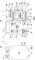
- the portable medical container 101 defines a housing having a first half portion 100a and a second half portion 100b.
- the first half portion 100a and the second half portion 100b are rotatably coupled to one another about a hinge "H".
- the hinge "H” is configured to permit rotational movement of the first half portion 100a and the second half portion 100b between a closed position ( FIG. 1 ) and an open position ( see FIG. 2 ).
- the hinge "H” may include one or more removable pins (not shown) which permit selective detachment and reattachment of the first half portion 100a and the second half portion 100b.
- first and second half portions 100a, 100b When the pins are removed, the first and second half portions 100a, 100b may be separated and positioned about a remote surgical theater 200 to facilitate clinician engagement with the components therein during surgical procedures. It is contemplated that the first and second half portions 100a, 100b may be coupled in any suitable manner (e.g., via clips, hinges, and the like).
- the first and second half portions 100a, 100b further include a plurality of housing supports 104 extending from an exterior surface of the first and second half portions 100a, 100b.
- the housing supports 104 may be coupled to an inner frame (not shown) enclosed by the first and second half portions 100a, 100b.
- the housing supports 104 distribute forces received by the first and second half portion 100a, 100b across the inner frame. Distribution of the forces associated with the weight of the portable medical system 100 along the internal frame maintains stability of the portable medical system 100 during surgical procedures and transportation. Distribution of the forces additionally reduces the chance for unintended application of force to the components of the portable medical system 100, which may cause harm to the components disposed therein.
- the portable medical system 100 includes an air intake port 106a, an air exhaust port 106b, a power input port 108a, and a power output port 108b.
- the air intake port 106a and air exhaust port 106b are coupled to, and are in fluid communication with, an air recirculation system 106 ( FIG. 2 ).
- the air recirculation system 106 which is used to filter air within a surgical space 202 ( FIG. 4 ), exchanges air within the surgical space 202 with air outside the surgical space (either in an air canister or air located directly outside the surgical space 202), or both.
- the air recirculation system 106 may be any suitable air propulsion system having one or more fans disposed therein.
- the air recirculation system 106 is enclosed within the second half portion 100b of the portable medical system 100.
- the air recirculation system 106 filters air prior to introduction to the surgical space 202.
- the air intake port 106a and air exhaust port 106b extend through the portable medical container 101, enabling ingress and egress of air to and from the air recirculation system 106.
- the air intake port 106A and air exhaust port 106B may further include filters, in addition to a filtration system enclosed in the air recirculation system 106, disposed therein capable of filtering particulates and air contaminants as air passes therethrough.
- the air intake port 106a and air exhaust port 106b may optionally be coupled to fluid caps (not shown) which prevent ingress or egress of air into or out of the air recirculation system 106, or contamination of the air recirculation system 106 during transportation of the portable medical system 100.
- the portable medical system 100 includes a power supply 108 having a power input port 108a and power output port 108b ( FIG. 2 ).
- the power input port 108a and the power output port 108b extend through the portable medical container 101 and enable external coupling of electrical cables and devices for electrically charging or distributing of electric power from the power supply 108.
- the power input port 108a is configured to receive either 110V or 220V connections to permit recharging of one or more batteries (not shown) located within the power supply 108.
- the power input port 108a may be any suitable port capable of receiving electrical power (e.g., alternating current (AC) or direct current (DC) electrical power) to charge the one or more batteries of the power supply 108, or power one or more devices coupled thereto.
- electrical power e.g., alternating current (AC) or direct current (DC) electrical power
- one or more solar collectors may be electrically coupled to the power input port 108a and provide electrical power, particularly when the portable medical system 100 is disposed in an environment where power connections are unavailable.
- the power output port 108b is configured to receive 110V or 220V connections, and permit transmission of electrical power to instruments which require electrical power for operation. Similar to the air intake port 106a and air exhaust port 106b, the power input port 108a and power output port 108b may include fluid caps (not shown) which prevent ingress of debris or fluids during transportation or operation of the portable medical system 100.
- the power supply 108 includes multiple receptacles 108c configured to receive and deliver power to electrical plugs connected thereto.
- the receptacles 108c are located within the portable medical container 101 and are accessible when the first and second half portions 100a, 100b of the portable medical container 101 are in the open configuration ( FIG. 2 ).
- the power output port 108b and the receptacles 108c may be selective powered by the power supply 108.
- the power supply 108 may supply power to the power output port 108b when the portable medical system 100 is in the closed configuration and alternatively may supply power to the receptacles 108c when the portable medical system 100 is in the open configuration.
- electrical power may be selectively transmitted to the power output port 108b or the receptacles 108c based on user input (e.g., via a switch (not shown)).
- An electrical charge indicator 108e is located along the power supply 108 and shows the battery state of charge.
- An electrosurgical generator 110 is enclosed within the second half portion 100b of the portable medical system 100.
- the electrosurgical generator 110 includes ports 110a which are configured to selectively receive electrosurgical instrument connectors (not shown) electrically coupled to one or more electrosurgical instruments 124.
- the electrosurgical generator 110 may be configured transmit electrical power to, without limitation, handheld devices such as monopolar energy delivery devices, bipolar energy delivery devices, surgical staplers configured to engage and seal vessels, and the like. Examples include, without limitation, the surgical devices described in U.S. Patent No. 9,375,282 , as well as U.S. Patent No. 9,375,258 , the entire contents of both of which are hereby incorporated by reference in their entirety.
- the electrosurgical generator 110 is configured to transmit electrosurgical energy for use by electrosurgical instruments 124 capable of transmitting either microwave energy or electrosurgical energy.
- the electrosurgical generator 110 is further configured to receive a return electrical current from the electrosurgical instruments 124 or electrosurgical instrument accessories (e.g., a return electrode or pad).
- the electrosurgical generator 110 is electrically coupled to the power supply 108, thereby permitting electrical communication between the power supply 108 and the electrosurgical generator 110.
- the electrosurgical generator 110 may be configured to be in either wired or wireless electrical communication with a computing device or console 128 and to transmit relevant information to the console 128 during a surgical procedure, e.g., the operational state, temperature, or life cycle information of the electrosurgical generator 110.
- Electrosurgical generators 110 suitable for inclusion may include Medtronic's ValleylabTM LS10 Generator, or other similar electrosurgical generators.
- a sterilization compartment 112 is positioned within the portable medical container 101 and is in electrical communication with the power supply 108.
- the sterilization compartment 112 includes a door 112d pivotably coupled to the second half portion 100b of the portable medical system 100 via hinges 112a. It is contemplated that the door 112d, along with the compartment doors described in the present application, may incorporate any suitable opening and closing mechanism.
- the door 112d is configured to enclose one or more surgical tools 120 or, more generally, objects disposed in a sterilization compartment "C2" enclosed by the door 112d.
- the door 112d includes a lock 112b which, when transitioned to a lock position, is configured to secure the door in a closed position relative to the sterilization compartment 112.
- the lock 112b may be in electrical communication with the power supply 108.
- the power supply 108 transmits electrical power to a UV light bulb located within the sterilization compartment "C2".
- the UV light bulb may transmit UV light at a preferred wavelength within the UV light spectrum (between approximately 400-180nm, including UV-A (400-320nm), UV-B (320-280nm), and UV-C (280-180nm)), to sterilize medical objects located in the sterilization compartment "C2".
- the sterilization compartment 112 may further include other sterilization units configured to disseminate objects disposed in the sterilization compartment "C2" such as, without limitation, an ozone generator, an air heating element, a gas dispersal device configured to disperse ethylene oxide, hydrogen peroxide vapor, hydrogen peroxide plasma, formaldehyde gas, and the like. Additionally, a microwave generator may be included to disperse microwaves into the compartment "C2" to disinfect objects disposed therein.
- the portable medical system 100 includes a UV light bulb 112c.
- the UV light bulb 112c similar to UV light bulb 112c included in the cavity "C1" of the portable medical system 100' ( FIG. 3 ), may deliver any suitable UV light within the UV light spectrum for disinfecting the contents enclosed in the sterilization compartment 112.
- the UV light bulb 112c is in electrical communication with the power supply 108.
- the power supply 108 includes a switch 108d which is configured to cause the power supply 108 to transmit electrical power to the UV light bulb 112c.
- the power supply 108 may periodically transmit electrical power to cause the UV light bulb 112c to emit light to disinfect the contents of the sterilization compartment 112.
- the power supply 108 may transmit electrical power when one or more predetermined events occur.
- the sterilization compartment 112 may be locked by a user after one or more surgical tools 120 are placed therein.
- the power supply 108 may receive a sensor signal indicating the closure, and in response, may transmit power to the UV light bulb 112c to disinfect the contents of the sterilization compartment. Transmission of electrical power by the power supply 108 to the UV light bulb 112c may be delayed by the power supply 108 to allow clinicians to close the portable medical container 101.
- the power supply 108 may intermittently (e.g., at a predetermined period or time interval) cause electrical power to be transmitted by the power supply 108 to the UV light bulb 112c.
- Transmission of UV light by the UV light bulb 112c may provide concentrated or prolonged sterilization of the contents located within the compartment "C1" of the portable medical container 101. For example, if certain components of the portable medical system 100 come into contact with contaminants such as, without limitation, the shroud 126, and are not sterilized in the sterilization compartment 112, during transportation or storage the power supply 108 may power the UV light bulb 112c to sterilize such components.
- a fluid delivery system 114 is located within the portable medical container 101 and is in electrical communication with the power supply 108.
- the fluid delivery system may be in wired or wireless communication with the console 128.
- the fluid delivery system includes an input port 114a and an output port 114b which are configured to receive and transmit fluids. More particularly, the fluid delivery system 114 may receive either liquids or gases during a surgical procedure. The liquids or gases may be distributed from one or more containers coupled to the fluid delivery system 114, such as a gas container 116 or an intravenous (IV) bag (not shown).
- IV intravenous
- the fluid delivery system 114 when connected to the gas container 116 or IV bag, may distribute the contents of the respective container to a patient to reduce pain, transition the patient into a partially or completely sedated state, or therapeutically treat the patient during surgical procedures.
- the fluid delivery system 114 may receive control signals from the computer or console 128 to regulate the flow of fluid to and from a patient.
- the second half portion 100b defines a cavity or compartment "C1" and includes a gas container 116, air recirculation piping or hoses 118, one or more surgical tools 120, an airway intubation kit 122, electrosurgical instruments 124, a tent or shroud 126, the console 128, and a portable imaging device 130.
- the first compartment “C1” is configured to receive items such as the gas container 116 or the portable imaging device 130 which are removable from the portable medical system 100, and may include one or more tie-downs "T".
- the tie-downs "T” may be constructed of rigid materials such as plastics or malleable materials such as flexible cord. When secured by the tie-downs "T" the contents located in the first compartment "C1" are prevented from shifting during transit, potentially leading to damage of the contents disposed within the first compartment "C1".
- the gas container 116 may include gasses to be delivered to patients to transition the patients to sedated states during surgical procedures. Additionally, the gas container 116 may include air with a heightened oxygen concentration or other gas mixtures for therapeutically treating patients.
- the airway intubation kit 122 may include a tracheostomy tube, a scalpel, one or more syringes, and other tools known in the art for establishing an airway in a patient.
- the electrosurgical instruments 124 may include, without limitation, electrosurgical pencils and forceps, monopolar or bipolar sealers, dissection devices such as harmonic scalpels, probes for electrosurgical ablation, probes for microwave ablation, and other similar electrosurgical instruments known in the art.
- the shroud 126 is configured to enclose a remote surgical theater 200 when deployed ( FIG. 4 ).
- the shroud 126 includes a frame 126a and a membrane 126b.
- the frame 126a is configured to support the membrane 126b thereon and to provide a semi-permeable or impermeable barrier between a surgical space 202 and the surrounding environment of the remote surgical theater 200.
- the membrane 126b includes entry flaps or doors 126c which enable ingress and egress of clinicians and patients through the membrane 126b.
- the membrane 126b includes a pair of fluid openings 126d disposed along the surface of the membrane 126b. The pair of fluid openings 126d may be operably connected to the air intake port 106a air exhaust port 106b.
- the membrane 126b includes a pair of electrical connection openings 126e which may be operably connected to the power input port 108a and power output port 108b.
- Air connection hoses or hoses 118 are configured to establish a fluid connection between the air intake port 106a or air exhaust port 106b of the air recirculation system 106 and the fluid openings 126d of the membrane 126b. In use, the hoses 118 permit the exchange and recirculation of air within a surgical space 202 formed when the shroud 126 is deployed.
- electrical power cables 132 are configured to operably couple the power supply 108 to an external power source (not shown). More particularly, when the remote surgical theater 200 ( FIG. 4 ) is within a predetermined distance from an external electrical power source (e.g., a portable power generator or an electrical outlet) the electrical power cables 132 may be coupled to both the external power source and the power input port 108a of the power supply 108.
- the console 128 may be any suitable computing device, such as the computing device 400 of FIG. 6 ) capable of, either via a wired or wireless connection, electrically communicating with the power supply 108, the electrosurgical generator 110, the portable imaging device 130, or any other device included in the portable medical system 100.
- the console 128 includes a communications interface or antenna capable of establishing a data connection either via wireless configurations, e.g., Wi-Fi®, Bluetooth, LTE, and/or wired configurations. Additionally, or alternatively, the communications interface may be capable of establishing wired or wireless connections with internet service providers via a wired or wireless configuration.
- wireless configurations e.g., Wi-Fi®, Bluetooth, LTE, and/or wired configurations.
- the communications interface may be capable of establishing wired or wireless connections with internet service providers via a wired or wireless configuration.
- the portable imaging device 130 may be any portable imaging device such as a portable ultrasound device or a portable x-ray device, capable of being housed within the compartment "C1" of the portable medical system 100.
- the portable imaging device 130 may further be configured electrically communicate with the console 128, either via a wired or wireless connection.
- the console 128 When the console 128 is in electrical communication with a remote console, the console 128 may operably connect the portable imaging device 130 with the remote console, enabling the transmission of data collected during use of the portable imaging device 130 by clinicians in the remote surgical theater 200 ( FIG. 4 ) to remote clinicians.
- data received from the portable imaging device 130 by the console 128 may be compressed prior to transmission to the remote console.
- the portable imaging device 130 may be included separately from the portable medical system 100, or may be any suitable portable imaging device configured to electrically communicate with the console 128.
- the portable medical system 100 may further include optional medical equipment (not shown) such as, without limitation, dialysis devices, additional or independent communications devices, electrocardiogram (ECG / EKG) monitors, electroencephalography machines, blood pressure monitoring devices, pulse oximeters, and the like. Further, disposable instruments such as electrodes, gloves, forceps, and the like may be included in the portable medical system 100.
- medical equipment such as, without limitation, dialysis devices, additional or independent communications devices, electrocardiogram (ECG / EKG) monitors, electroencephalography machines, blood pressure monitoring devices, pulse oximeters, and the like.
- disposable instruments such as electrodes, gloves, forceps, and the like may be included in the portable medical system 100.
- An example of suitable medical equipment for inclusion in the portable medical system 100 includes portable therapy deliver devices described in commonly-owned U.S. Patent Application Publication No. 2006/0270916 , entitled "PORTABLE THERAPY DELIVERY DEVICE WITH A REMOVABLE CONNECTOR BOARD" the entire contents of
- Adapters may be included in the portable medical system 100 to facilitate interconnection between components included in the portable medical system 100 and surgical equipment available at a remote surgical theater 200 ( see FIG. 4 ).
- the console 128 may be coupled to imaging devices available at remote locations (e.g., a magnetic resonance imaging (MRI) machine or an x-ray machine) via an adapter (not shown).
- imaging devices available at remote locations e.g., a magnetic resonance imaging (MRI) machine or an x-ray machine
- electrosurgical generators, or other surgical equipment available at the remote surgical theater 200 may be coupled to the console 128 or the power supply 108 via adapters to enable the portable medical system 100 to engage and/or power the available surgical equipment.
- the console 128 When connected to surgical equipment available at the remote surgical theater 200, the console 128 may receive data from the surgical equipment and display the data determined to be relevant to the surgical procedure being performed. Additionally, the surgical equipment, when in electrical communication with the console 128, may be operably coupled to remote consoles (not shown), enabling remote clinicians to analyze data received from the remote surgical equipment. For example, during a telemedical procedure, clinicians at remote surgical theaters 200 may couple a portable X-ray scanner to the console 128 to collect one or more X-ray images of a patient. The console 128 may subsequently transmit the images, periodically or in real time, to clinicians located remotely for analysis. Analysis performed by the remote clinicians may be incorporated into feedback which is transmitted back to the console 128 to assist the clinicians during the surgical procedure ( see FIG. 5 ).
- FIG. 3 illustrated is an alternative embodiment of the portable medical system 100, in which the components of the portable medical system 100 are distributed across two portable medical containers 100a', 100a".
- the components of the portable medical system 100 are distributed across the two portable medical containers 100a', 100a".
- the overall weight of the portable medical system 100 is dispersed. It is contemplated that, depending on the components included in the portable medical system 100, when the collective weight of the portable medical system 100 reaches an undesirable weight (e.g., fifty pounds) or more the two portable medical containers 100a', 100a" may be transported to the remote surgical theater 200 ( FIG. 4 ) as a distributed portable medical system 100'.
- an undesirable weight e.g., fifty pounds
- each container 100a', 100a” may include either air intake port 106a and air exhaust port 106b, power input port 108a and power output port 108b, or any combination of ports thereof.
- each container clinicians may selectively include the air recirculation system 106 and the power supply 108 within the portable medical containers 101', 101".
- FIG. 4 illustrates a remote surgical theater 200.
- a clinician assembles the frame 126a of the shroud 126 to form an assembled frame 126a. Once the frame 126a is assembled the membrane 126b is placed or draped over the frame 126a. If an existing structure is available at the remote surgical theater 200, assembly of the frame 126a may not be necessary, and the membrane 126b may be draped over the existing structure. Draping the membrane 126b over the frame 126a encloses a surgical space 202 which is shielded from weather or distractions including, without limitation, rain, sunlight, and sound.
- the surgical space 202 includes a surgical table "ST" on which a patient "P" may be disposed.
- clinicians may interact with the console 128.
- the console 128 may have a camera and microphone disposed thereon (not explicitly shown) to collect audio and video data.
- the console 128 may transmit the received data to one or more remote consoles.
- the console 128 may compress the data prior to transmission.
- a clinician may view the surgical procedure, and instruct the clinician during the surgical procedure when desired.
- the clinician at the remote console may monitor the state of the patient "P" and indicate to the clinician performing the surgical procedure the state of the patient "P".
- the clinician at the remote console may indicate such to the clinician performing the surgical procedure.
- the clinician at the remote console may supply user input to the remote console 128 to control one or more components in electrical communication with the console 128 disposed in the surgical space 202 such as, without limitation, the electrosurgical generator 110, the air recirculation system 106, and the like.
- the membrane 126b may be formed from any semi-permeable or non-permeable material and may be transparent, translucent, or opaque, depending on the level of privacy desired.
- the membrane 126b forms a pair of doors 126c to permit ingress or egress of clinicians and/or patients into and out of the surgical space 202.
- the membrane 126b further includes a first pair of fluid openings 126d and a second pair of electrical connection openings 126e. The first pair of fluid openings 126d and the second pair of electrical connection openings 126e are disposed along a surface of the membrane 126b.
- the first pair of fluid openings 126d are configured to have the hoses 118 coupled thereto to permit communication of air outside the surgical space 202 to and from the air recirculation system 106.
- the second pair of electrical connection openings 126e are configured to permit a pair of electrical power cables 132 to pass through the membrane 126b, enabling external coupling of the power supply 108 to external power sources. Where no external power sources are available, the second pair of electrical connection openings 126e may be sealed by coupling a cap (not shown) to the openings so as to prevent ingress or egress of fluid or contaminants into and out of the surgical space 202.
- communication between the console 128 ( FIG. 4 ) and one or more remote consoles may occur, the communication process generally referred to as process 300.
- the present disclosure contemplates communication between the console 128 located at the remote surgical theater 200 and any other suitable computing device capable of receiving and transmitting data in real time between the clinician engaging the console 128 and one or more remote clinicians assisting during the procedure.
- a clinician may position the console 128 within the surgical space 202 in a desirable location for easy access during a surgical procedure.
- the console 128 may be battery operated or may electrically couple to the power supply 108 located in the portable medical container 101. Electrical communication may be established between the console 128 and the one or more devices included in the portable medical system 100.
- the console 128 may wirelessly communicate with the electrosurgical generator 110 to provide information regarding operation of the electrosurgical generator 110 during the surgical procedure.
- the console 128 receives data from the device or devices in electrical communication with the console 128 (S302), relevant information is displayed via a display of the console 128 or transmitted as audio output to the clinician from the console 128 (S304).
- the console 128 determines whether communication has been established with a remote console (S306). More particularly, the console 128 determines if communication has been established between the console 128 located in the remote surgical theater 200, and the remote console 128 (not shown) where the remote clinician is located. If communication is not established, the console 128 continues to receive communications (S302) and display the relevant data to the clinician during the surgical procedure, while optionally indicating that communication has not been established with the remote console 128 (not shown). (S304). Alternatively, once the console 128 determines that communication has been established with a remote console (S306) the console 128 in the remote surgical theater 200 compresses the data received during the surgical procedure in anticipation of transmission to the remote console 128 (S308). The console 128 in the remote surgical theater 200 then transmits the compressed data to the remote console, the data transmitted to enable the remote clinician to assist the acting clinician during the procedure (S310). The console 128 may also encrypt the data prior to transmission to the remote console 128.
- the clinician at the remote console 128 may input feedback to be transmitted to the clinician performing the procedure.
- the clinician performing the procedure may navigate an electrosurgical instrument 124 to a target site in a patient.
- the remote clinician may indicate how to more precisely navigate through the patient, where to apply electrosurgical energy, how much electrosurgical energy to apply to a particular target site, etc.
- the data associated with the input of information by the clinician at the remote site may be compressed prior to transmission to the console 128 in the remote surgical theater 200 (S312).
- the console 128 receives data from the remote console, the data is displayed on the console 128 (via one or more display units or screens) or output via an audio output device integrated in the console 128 (S314). This process 300 is repeated until the clinician disables communication between the console 128 and the remote console.
- process 300 may be interrupted at any point to verify that electrical communication between the console 128 in the remote surgical theater 200 and the remote console 128 is maintained. If the electrical communication is interrupted, process 300 may leave any particular step and repeat by re-executing the process 300. It is contemplated that, in embodiments, the console 128 may receive input solely from a patient (without the aid of a clinician at the console 128), thereby enabling communication with the patient and the remote clinician at the remote console 128. Further, in embodiments, the console 128 may receive sensor signals from the devices during a particular surgical procedure, the devices disposed in the remote surgical theater and in either wired or wireless electrical communication with the console 128.
- remote console 128 may execute one or more sets of instructions which, when executed, process the received sensor signals.
- the instructions may generate images associated with the sensor signals for display on the console 128. More particularly, the generated images may be overlaid onto the images received from the remote console for display on the console 128, or adjacent to the images received by the remote console.
- the sensor data may be processed and used to generate images or video indicative of the data collected to be displayed. The generated images or video may then be overlaid onto the video being displayed by the console 128 during the surgical procedure.
- the console 128 is configured to receive sensor signals from one or more portable imaging devices 130 and, based on the sensor signals, generate an image or series of images (video, etc.) to be displayed on the console 128. It is contemplated that, in embodiments.
- the computing device 400 may represent one or more components (e.g., console 128, or a control system associated with the air recirculation system 106, the power supply 108, the electrosurgical generator 110, the sterilization compartment 112, the fluid delivery system 114, and/or any of the components included in the cavity "C1" of the portable medical system 100.
- components e.g., console 128, or a control system associated with the air recirculation system 106, the power supply 108, the electrosurgical generator 110, the sterilization compartment 112, the fluid delivery system 114, and/or any of the components included in the cavity "C1" of the portable medical system 100.
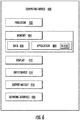
- the computing device 400 may include one or more memories 404, processors 402 in electrical communication with the memories 404, display devices or displays 412, network interfaces 418, input devices 414, and/or output modules 416, or any desired subset of components thereof.
- the memory 404 may include non-transitory computer-readable storage media for storing data and/or software which include instructions to be executed on the one or more processors 402 and which, when executed, control operation of the computing device 400.
- the memory 404 may include one or more solid-state storage devices such as flash memory chips.
- the memory 404 may include one or more mass storage devices connected to the processor 402 through a mass storage controller and a communications bus (not shown).
- computer-readable storage media may include any available media that can be accessed by the processor 402. More particularly, computer readable storage media may include non-transitory, volatile, non-volatile, removable, non-removable media, and the like, implemented in any method or technology for storage of information such as computer readable instructions, data structures, program modules, or other suitable data access and management systems.
- Examples of computer-readable storage media include RAM, ROM, EPROM, EEPROM, flash memory, or other known solid state memory technology, CD-ROM, DVD, Blu-Ray or other such optical storage, magnetic cassettes, magnetic tape, magnetic desk storage or other magnetic storage devices, or any other medium which may be used to store information and which can be accessed by computing device 400.
- the memory 404 stores data 406 and/or one or more applications 408.
- the applications 408 may include instructions which are executed on the one or more processors 402 of the computing device 400.
- the application 408 may include instructions which cause a user interface controller 410 to control the display 412 such that a user interface controller 410 is displayed (e.g., a graphical user interface (GUI)).
- GUI graphical user interface
- the network interface 418 is configured to couple the computing device 400 and/or individual components thereof to a network, such as a wired network, a wireless network, a local area network (LAN), a wide area network (WAN), a wireless mobile network, a Bluetooth® network, the Internet, and the like.
- the input device 414 may be any device a user may engage to enter input.
- the input device 414 may include a mouse, keyboard, touch-capacitive display, voice interface, and/or the like.
- the output module 416 may, in embodiments, include any connectivity port or bus, such as, for example, a parallel port, a serial port, a universal serial bus (USB), or any other similar connectivity port known in the art.
Landscapes
- Health & Medical Sciences (AREA)
- Life Sciences & Earth Sciences (AREA)
- Public Health (AREA)
- Engineering & Computer Science (AREA)
- General Health & Medical Sciences (AREA)
- Animal Behavior & Ethology (AREA)
- Veterinary Medicine (AREA)
- Biomedical Technology (AREA)
- Surgery (AREA)
- Nuclear Medicine, Radiotherapy & Molecular Imaging (AREA)
- Medical Informatics (AREA)
- Epidemiology (AREA)
- Heart & Thoracic Surgery (AREA)
- Molecular Biology (AREA)
- Radiology & Medical Imaging (AREA)
- Pathology (AREA)
- Primary Health Care (AREA)
- Physics & Mathematics (AREA)
- Oral & Maxillofacial Surgery (AREA)
- Otolaryngology (AREA)
- Plasma & Fusion (AREA)
- Electromagnetism (AREA)
- Gynecology & Obstetrics (AREA)
- Business, Economics & Management (AREA)
- Urology & Nephrology (AREA)
- General Business, Economics & Management (AREA)
- Nursing (AREA)
- Orthopedic Medicine & Surgery (AREA)
- Human Computer Interaction (AREA)
- Chemical & Material Sciences (AREA)
- Chemical Kinetics & Catalysis (AREA)
- General Chemical & Material Sciences (AREA)
- Surgical Instruments (AREA)
- Apparatus For Disinfection Or Sterilisation (AREA)
Abstract
Description
- The present disclosure relates to portable telemedicine and telemedical systems and, more particularly, to deployable system for creating and sustaining a portable surgical theater in remote locations.
- Systems and methods have been developed and are known in the art to provide therapeutic medical treatments to patients who are not in a controlled surgical environment such as hospitals or clinician offices. For example, portable containers with medical supplies, commonly referred to as first aid kits, are often used by clinicians such as doctors and paramedics to transport equipment useful for delivering medical care to patients who are otherwise unable to travel to a medical facility. These first aid kits may include a variety of tools, such as prepackaged sterilized equipment and medicines.
Additionally, systems for providing specific therapeutic treatments are often enclosed in stand-alone kits, such as defibrillators, intubation kits, and vital sign measurement kits ("stand-alone kits"). These stand-alone kits are designed to maintain sterility prior to use by clinicians, and are generally directed to providing life-sustaining support to a patient prior to transportation of the patient to a medical facility. While these tools and methods are sufficient for short-term medical treatment of patients (e.g., stabilization of the patient), there exists a need for systems and methods that facilitate prolonged remote therapeutic treatment to patients. - In accordance with an aspect of the present disclosure, a portable medical system for deploying a remote surgical theater includes a portable medical container, a sanitization compartment, and a power supply. The portable medical container is transitionable between a closed position and an open position. The sanitization compartment is disposed within the portable medical container and transitionable between a closed position and an open position. The power supply is disposed within the portable medical container and is configured to selectively supply electrical power to the sanitization compartment. The power supply is configured to receive user input and, in response to the user input, transmit the electrical power to the sanitization compartment.
- In aspects, the sanitization compartment may be configured to transmit UV light in response to receiving the electrical power. The sanitization compartment may be configured to release a sanitization agent including ozone gas, heated air, ethylene oxide, microwave-energy, hydrogen peroxide vapor, hydrogen peroxide plasma, and/or formaldehyde gas. The sterilization compartment may be removably disposed within the portable medical container.
- According to aspects, the portable medical container may further include a compartment selected from the group consisting of a fluid delivery compartment, an electrosurgical generator, a removable power supply, and an air recirculation system compartment. The compartment may be removable.
- In aspects, the portable medical system may further include a shroud having at least one opening configured to have an air connection hose coupled thereto to facilitate air circulation thereacross. The portable medical system may include a console configured to be in electrical communication with the power supply and/or a remote console. The portable medical system may include at least one medical device selected from the group consisting of an imaging device, an electrically powered surgical instrument, and an electrosurgical instrument.
- According to aspects, the power supply may be configured to receive electrical power from an external power source and, in response to receiving the electrical power, store the electrical power in one or more batteries disposed in the power supply. The console may be configured to establish wireless communication with a remote console.
- In aspects, when wireless communication is established between the console and the remote console, the console is configured to receive user input at the console, transmit the user input to the remote console, and in response to transmitting the user input, receive second user input at the remote console. When wireless communication is established, the console may further be configured to display the second user input on a display of the console.
- In accordance with an aspect of the present disclosure, a method of monitoring a telemedical procedure includes deploying a console at a remote surgical theater located in a first location, establishing electrical communication with a second console in a second location, inputting user input into the console at the first location to be transmitted to a clinician interacting with the second console at the second location, transmitting the user input from the console at the first location to the console at the second location, receiving at the console at the first location, in response to transmitting the user input, second user input received at the second console, and displaying the second user input on a display of the console at the first location.
- In aspects, the method may further include compressing the user input received at the console at the first location prior to the transmitting. The method may further include compressing the second user input received at the second console prior to the receiving. The method may further include receiving, at the console at the first location, instructions to control a surgical device in electrical communication with the console, and transmitting control signals from the console based on the instructions to control the surgical device.
- The accompanying drawings, which are incorporated in and constitute a part of the specification, illustrate embodiments of the disclosure and, together with a general description of the disclosure given above, and the detailed description of the embodiment given below, serve to explain the principles of the disclosure.
-
FIG. 1 is a perspective view of a first portable telemedicine kit in a closed position, in accordance with an embodiment of the present disclosure; -
FIG. 2 is a plan view of the first portable telemedicine kit ofFIG. 1 in an open position; -
FIG. 3 is a plan view of an alternate embodiment of the portable telemedicine kit ofFIG. 1 , including a first and second portable telemedicine kit, in accordance with an embodiment of the present disclosure; -
FIG. 4 is a perspective view of a surgical theater having the portable telemedicine kit ofFIG. 1 disposed therein, in accordance with an embodiment of the present disclosure; -
FIG. 5 is a flow diagram illustrating electrical communication between a console of the portable telemedicine kit ofFIG. 1 and one or more remote consoles; and -
FIG. 6 is a schematic block diagram of a computing device that may be employed according to various embodiments of this disclosure. - Systems which enable the construction of a portable medical environment, as disclosed herein, may be housed in one or more transportable containers. More particularly, these portable medical systems include equipment for sustaining a surgical theater in a location remote from an established medical facility. The portable medical systems may contain equipment found in hospitals, in-patient or out-patient medical facilities, and the like. The equipment included in the portable medical systems may be permanently integrated or removably coupled to individual portable containers. Alternatively, the equipment of any portable medical system may be distributed across multiple portable containers as a distributed the portable medical system and increase the ease of transport of the portable medical system.
- Equipment included in portable medical systems may include one or more therapeutic treatment systems such as, without limitation, electrosurgical generators, airway intubation kits, surgical tools and accessories, and the like. These therapeutic treatment systems are housed within one or more containers, such as soft-side containers ("bags") or hard containers such as hard plastic containers and metal containers. In embodiments, multiple containers may be operably interconnected to allow for the distribution and interconnection of therapeutic treatment systems. As will be discussed later in detail, the therapeutic treatment systems include components such as, without limitation, a surgical shroud, an air filtration and recirculation system, an ultra-violet sterilization system, and a telecommunication system. Distribution of these components may permit a clinician to disperse the weight and size of each of the portable containers of the various portable medical systems, which in turn may enable the described portable medical systems to be deployed to remote locations which otherwise do not have access to permanent medical facilities.
- Embodiments of the present disclosure are described in detail with reference to the drawings, in which like reference numerals designate identical or corresponding elements across the several included views. As defined herein, the term "clinician" refers to a doctor, nurse, or other care provider and may include support personnel. The term "distal" refers to structure that is farther from a clinician, while the term "proximal" refers to structure that is closer to the clinician. Further, directional terms such as front, rear, upper, lower, top, bottom, distal, proximal, and the like are used to assist in understanding the description and are not intended to limit the present disclosure.
- As will be described in detail, the provided descriptions illustrate embodiments of portable medical systems for selectively deploying a portable medical environment, the portable medical systems designated generally 100. The portable
medical system 100 may be contained in a single portable medical container 101 (FIG. 1 ), or distributed across multiple portablemedical containers 101', 101" (FIG. 3 ). The portablemedical containers FIGS. 1-3 ) may include multiple interchangeable compartments (i.e., a sterilization compartment 112). In embodiments, certain interchangeable compartments may be fixed or otherwise permanently affixed to and integrated with the portablemedical containers medical container 101 includes at least one compartment "C1" (FIG. 2 ) dimensioned to store components such as, without limitation, a surgical shroud orshroud 126 and surgical tools 120 (seeFIG. 1 ). The portablemedical systems 100 may further include anair recirculation system 106, apower supply 108, anelectrosurgical generator 110, asterilization compartment 112, and a gas orfluid delivery system 114. It is contemplated that the portablemedical system 100 of the present disclosure may, in embodiments, contain any subset of components or containers thereof. - Referring initially to
FIG. 1 , a portablemedical system 100 includes a portablemedical container 101. The portablemedical container 101 defines a housing having afirst half portion 100a and asecond half portion 100b. Thefirst half portion 100a and thesecond half portion 100b are rotatably coupled to one another about a hinge "H". The hinge "H" is configured to permit rotational movement of thefirst half portion 100a and thesecond half portion 100b between a closed position (FIG. 1 ) and an open position (seeFIG. 2 ). The hinge "H" may include one or more removable pins (not shown) which permit selective detachment and reattachment of thefirst half portion 100a and thesecond half portion 100b. When the pins are removed, the first andsecond half portions surgical theater 200 to facilitate clinician engagement with the components therein during surgical procedures. It is contemplated that the first andsecond half portions - The first and
second half portions housing supports 104 extending from an exterior surface of the first andsecond half portions second half portions medical system 100 is placed on a surface (e.g., the ground or along a table), the housing supports 104 distribute forces received by the first andsecond half portion medical system 100 along the internal frame maintains stability of the portablemedical system 100 during surgical procedures and transportation. Distribution of the forces additionally reduces the chance for unintended application of force to the components of the portablemedical system 100, which may cause harm to the components disposed therein. - With continued reference to
FIG. 1 , the portablemedical system 100 includes anair intake port 106a, anair exhaust port 106b, apower input port 108a, and apower output port 108b. Theair intake port 106a andair exhaust port 106b are coupled to, and are in fluid communication with, an air recirculation system 106 (FIG. 2 ). Theair recirculation system 106, which is used to filter air within a surgical space 202 (FIG. 4 ), exchanges air within thesurgical space 202 with air outside the surgical space (either in an air canister or air located directly outside the surgical space 202), or both. Theair recirculation system 106 may be any suitable air propulsion system having one or more fans disposed therein. Theair recirculation system 106 is enclosed within thesecond half portion 100b of the portablemedical system 100. In embodiments, theair recirculation system 106 filters air prior to introduction to thesurgical space 202. Theair intake port 106a andair exhaust port 106b extend through the portablemedical container 101, enabling ingress and egress of air to and from theair recirculation system 106. The air intake port 106A and air exhaust port 106B may further include filters, in addition to a filtration system enclosed in theair recirculation system 106, disposed therein capable of filtering particulates and air contaminants as air passes therethrough. Theair intake port 106a andair exhaust port 106b may optionally be coupled to fluid caps (not shown) which prevent ingress or egress of air into or out of theair recirculation system 106, or contamination of theair recirculation system 106 during transportation of the portablemedical system 100. - The portable
medical system 100 includes apower supply 108 having apower input port 108a andpower output port 108b (FIG. 2 ). Thepower input port 108a and thepower output port 108b extend through the portablemedical container 101 and enable external coupling of electrical cables and devices for electrically charging or distributing of electric power from thepower supply 108. Specifically, thepower input port 108a is configured to receive either 110V or 220V connections to permit recharging of one or more batteries (not shown) located within thepower supply 108. In embodiments, thepower input port 108a may be any suitable port capable of receiving electrical power (e.g., alternating current (AC) or direct current (DC) electrical power) to charge the one or more batteries of thepower supply 108, or power one or more devices coupled thereto. For example, one or more solar collectors (or solar panels) may be electrically coupled to thepower input port 108a and provide electrical power, particularly when the portablemedical system 100 is disposed in an environment where power connections are unavailable. Likewise, thepower output port 108b is configured to receive 110V or 220V connections, and permit transmission of electrical power to instruments which require electrical power for operation. Similar to theair intake port 106a andair exhaust port 106b, thepower input port 108a andpower output port 108b may include fluid caps (not shown) which prevent ingress of debris or fluids during transportation or operation of the portablemedical system 100. - The
power supply 108 includesmultiple receptacles 108c configured to receive and deliver power to electrical plugs connected thereto. Thereceptacles 108c are located within the portablemedical container 101 and are accessible when the first andsecond half portions medical container 101 are in the open configuration (FIG. 2 ). During operation, thepower output port 108b and thereceptacles 108c may be selective powered by thepower supply 108. For example, thepower supply 108 may supply power to thepower output port 108b when the portablemedical system 100 is in the closed configuration and alternatively may supply power to thereceptacles 108c when the portablemedical system 100 is in the open configuration. Alternatively, electrical power may be selectively transmitted to thepower output port 108b or thereceptacles 108c based on user input (e.g., via a switch (not shown)). Anelectrical charge indicator 108e is located along thepower supply 108 and shows the battery state of charge. - An
electrosurgical generator 110 is enclosed within thesecond half portion 100b of the portablemedical system 100. Theelectrosurgical generator 110 includesports 110a which are configured to selectively receive electrosurgical instrument connectors (not shown) electrically coupled to one or moreelectrosurgical instruments 124. For example, theelectrosurgical generator 110 may be configured transmit electrical power to, without limitation, handheld devices such as monopolar energy delivery devices, bipolar energy delivery devices, surgical staplers configured to engage and seal vessels, and the like. Examples include, without limitation, the surgical devices described inU.S. Patent No. 9,375,282 U.S. Patent No. 9,375,258 electrosurgical generator 110 is configured to transmit electrosurgical energy for use byelectrosurgical instruments 124 capable of transmitting either microwave energy or electrosurgical energy. Theelectrosurgical generator 110 is further configured to receive a return electrical current from theelectrosurgical instruments 124 or electrosurgical instrument accessories (e.g., a return electrode or pad). Theelectrosurgical generator 110 is electrically coupled to thepower supply 108, thereby permitting electrical communication between thepower supply 108 and theelectrosurgical generator 110. Theelectrosurgical generator 110 may be configured to be in either wired or wireless electrical communication with a computing device orconsole 128 and to transmit relevant information to theconsole 128 during a surgical procedure, e.g., the operational state, temperature, or life cycle information of theelectrosurgical generator 110.Electrosurgical generators 110 suitable for inclusion may include Medtronic's Valleylab™ LS10 Generator, or other similar electrosurgical generators. - A
sterilization compartment 112 is positioned within the portablemedical container 101 and is in electrical communication with thepower supply 108. Thesterilization compartment 112 includes adoor 112d pivotably coupled to thesecond half portion 100b of the portablemedical system 100 viahinges 112a. It is contemplated that thedoor 112d, along with the compartment doors described in the present application, may incorporate any suitable opening and closing mechanism. Thedoor 112d is configured to enclose one or moresurgical tools 120 or, more generally, objects disposed in a sterilization compartment "C2" enclosed by thedoor 112d. Thedoor 112d includes alock 112b which, when transitioned to a lock position, is configured to secure the door in a closed position relative to thesterilization compartment 112. Thelock 112b may be in electrical communication with thepower supply 108. When thelock 112b is transitioned by a clinician from the unlock position to the lock position, thepower supply 108 transmits electrical power to a UV light bulb located within the sterilization compartment "C2". The UV light bulb may transmit UV light at a preferred wavelength within the UV light spectrum (between approximately 400-180nm, including UV-A (400-320nm), UV-B (320-280nm), and UV-C (280-180nm)), to sterilize medical objects located in the sterilization compartment "C2". It is contemplated that thesterilization compartment 112 may further include other sterilization units configured to disseminate objects disposed in the sterilization compartment "C2" such as, without limitation, an ozone generator, an air heating element, a gas dispersal device configured to disperse ethylene oxide, hydrogen peroxide vapor, hydrogen peroxide plasma, formaldehyde gas, and the like. Additionally, a microwave generator may be included to disperse microwaves into the compartment "C2" to disinfect objects disposed therein. - Additionally, the portable
medical system 100 includes a UVlight bulb 112c. The UVlight bulb 112c, similar to UVlight bulb 112c included in the cavity "C1" of the portable medical system 100' (FIG. 3 ), may deliver any suitable UV light within the UV light spectrum for disinfecting the contents enclosed in thesterilization compartment 112. The UVlight bulb 112c is in electrical communication with thepower supply 108. Thepower supply 108 includes aswitch 108d which is configured to cause thepower supply 108 to transmit electrical power to the UVlight bulb 112c. In embodiments, thepower supply 108 may periodically transmit electrical power to cause the UVlight bulb 112c to emit light to disinfect the contents of thesterilization compartment 112. Also, in embodiments, thepower supply 108 may transmit electrical power when one or more predetermined events occur. For example, thesterilization compartment 112 may be locked by a user after one or moresurgical tools 120 are placed therein. Once locked, thepower supply 108 may receive a sensor signal indicating the closure, and in response, may transmit power to the UVlight bulb 112c to disinfect the contents of the sterilization compartment. Transmission of electrical power by thepower supply 108 to the UVlight bulb 112c may be delayed by thepower supply 108 to allow clinicians to close the portablemedical container 101. Alternatively, thepower supply 108 may intermittently (e.g., at a predetermined period or time interval) cause electrical power to be transmitted by thepower supply 108 to the UVlight bulb 112c. Transmission of UV light by theUV light bulb 112c may provide concentrated or prolonged sterilization of the contents located within the compartment "C1" of the portablemedical container 101. For example, if certain components of the portablemedical system 100 come into contact with contaminants such as, without limitation, theshroud 126, and are not sterilized in thesterilization compartment 112, during transportation or storage thepower supply 108 may power the UVlight bulb 112c to sterilize such components. - A
fluid delivery system 114 is located within the portablemedical container 101 and is in electrical communication with thepower supply 108. The fluid delivery system may be in wired or wireless communication with theconsole 128. The fluid delivery system includes aninput port 114a and anoutput port 114b which are configured to receive and transmit fluids. More particularly, thefluid delivery system 114 may receive either liquids or gases during a surgical procedure. The liquids or gases may be distributed from one or more containers coupled to thefluid delivery system 114, such as agas container 116 or an intravenous (IV) bag (not shown). Thefluid delivery system 114, when connected to thegas container 116 or IV bag, may distribute the contents of the respective container to a patient to reduce pain, transition the patient into a partially or completely sedated state, or therapeutically treat the patient during surgical procedures. Thefluid delivery system 114 may receive control signals from the computer orconsole 128 to regulate the flow of fluid to and from a patient. - With continued reference to
FIG. 2 , thesecond half portion 100b defines a cavity or compartment "C1" and includes agas container 116, air recirculation piping orhoses 118, one or moresurgical tools 120, anairway intubation kit 122,electrosurgical instruments 124, a tent orshroud 126, theconsole 128, and aportable imaging device 130. The first compartment "C1" is configured to receive items such as thegas container 116 or theportable imaging device 130 which are removable from the portablemedical system 100, and may include one or more tie-downs "T". The tie-downs "T" may be constructed of rigid materials such as plastics or malleable materials such as flexible cord. When secured by the tie-downs "T" the contents located in the first compartment "C1" are prevented from shifting during transit, potentially leading to damage of the contents disposed within the first compartment "C1". - The
gas container 116 may include gasses to be delivered to patients to transition the patients to sedated states during surgical procedures. Additionally, thegas container 116 may include air with a heightened oxygen concentration or other gas mixtures for therapeutically treating patients. Theairway intubation kit 122 may include a tracheostomy tube, a scalpel, one or more syringes, and other tools known in the art for establishing an airway in a patient. Theelectrosurgical instruments 124 may include, without limitation, electrosurgical pencils and forceps, monopolar or bipolar sealers, dissection devices such as harmonic scalpels, probes for electrosurgical ablation, probes for microwave ablation, and other similar electrosurgical instruments known in the art. - The
shroud 126 is configured to enclose a remotesurgical theater 200 when deployed (FIG. 4 ). Theshroud 126 includes aframe 126a and amembrane 126b. Theframe 126a is configured to support themembrane 126b thereon and to provide a semi-permeable or impermeable barrier between asurgical space 202 and the surrounding environment of the remotesurgical theater 200. Themembrane 126b includes entry flaps ordoors 126c which enable ingress and egress of clinicians and patients through themembrane 126b. Themembrane 126b includes a pair offluid openings 126d disposed along the surface of themembrane 126b. The pair offluid openings 126d may be operably connected to theair intake port 106aair exhaust port 106b. Likewise, themembrane 126b includes a pair ofelectrical connection openings 126e which may be operably connected to thepower input port 108a andpower output port 108b. - Air connection hoses or
hoses 118 are configured to establish a fluid connection between theair intake port 106a orair exhaust port 106b of theair recirculation system 106 and thefluid openings 126d of themembrane 126b. In use, thehoses 118 permit the exchange and recirculation of air within asurgical space 202 formed when theshroud 126 is deployed. Likewise,electrical power cables 132 are configured to operably couple thepower supply 108 to an external power source (not shown). More particularly, when the remote surgical theater 200 (FIG. 4 ) is within a predetermined distance from an external electrical power source (e.g., a portable power generator or an electrical outlet) theelectrical power cables 132 may be coupled to both the external power source and thepower input port 108a of thepower supply 108. - The
console 128 may be any suitable computing device, such as thecomputing device 400 ofFIG. 6 ) capable of, either via a wired or wireless connection, electrically communicating with thepower supply 108, theelectrosurgical generator 110, theportable imaging device 130, or any other device included in the portablemedical system 100. Theconsole 128 includes a communications interface or antenna capable of establishing a data connection either via wireless configurations, e.g., Wi-Fi®, Bluetooth, LTE, and/or wired configurations. Additionally, or alternatively, the communications interface may be capable of establishing wired or wireless connections with internet service providers via a wired or wireless configuration. A detailed description of communication between theconsole 128 and one or more remote consoles (not shown) will be described with reference toFIG. 5 . - The
portable imaging device 130 may be any portable imaging device such as a portable ultrasound device or a portable x-ray device, capable of being housed within the compartment "C1" of the portablemedical system 100. Theportable imaging device 130 may further be configured electrically communicate with theconsole 128, either via a wired or wireless connection. When theconsole 128 is in electrical communication with a remote console, theconsole 128 may operably connect theportable imaging device 130 with the remote console, enabling the transmission of data collected during use of theportable imaging device 130 by clinicians in the remote surgical theater 200 (FIG. 4 ) to remote clinicians. As will be discussed later, data received from theportable imaging device 130 by theconsole 128 may be compressed prior to transmission to the remote console. In embodiments, theportable imaging device 130 may be included separately from the portablemedical system 100, or may be any suitable portable imaging device configured to electrically communicate with theconsole 128. - It is contemplated that the portable
medical system 100 may further include optional medical equipment (not shown) such as, without limitation, dialysis devices, additional or independent communications devices, electrocardiogram (ECG / EKG) monitors, electroencephalography machines, blood pressure monitoring devices, pulse oximeters, and the like. Further, disposable instruments such as electrodes, gloves, forceps, and the like may be included in the portablemedical system 100. An example of suitable medical equipment for inclusion in the portablemedical system 100 includes portable therapy deliver devices described in commonly-ownedU.S. Patent Application Publication No. 2006/0270916 , entitled "PORTABLE THERAPY DELIVERY DEVICE WITH A REMOVABLE CONNECTOR BOARD" the entire contents of which are hereby incorporated by reference. - Adapters (not shown) may be included in the portable
medical system 100 to facilitate interconnection between components included in the portablemedical system 100 and surgical equipment available at a remote surgical theater 200 (seeFIG. 4 ). For example, in addition to or in place of theportable imaging device 130, theconsole 128 may be coupled to imaging devices available at remote locations (e.g., a magnetic resonance imaging (MRI) machine or an x-ray machine) via an adapter (not shown). Likewise, electrosurgical generators, or other surgical equipment available at the remotesurgical theater 200 may be coupled to theconsole 128 or thepower supply 108 via adapters to enable the portablemedical system 100 to engage and/or power the available surgical equipment. - When connected to surgical equipment available at the remote
surgical theater 200, theconsole 128 may receive data from the surgical equipment and display the data determined to be relevant to the surgical procedure being performed. Additionally, the surgical equipment, when in electrical communication with theconsole 128, may be operably coupled to remote consoles (not shown), enabling remote clinicians to analyze data received from the remote surgical equipment. For example, during a telemedical procedure, clinicians at remotesurgical theaters 200 may couple a portable X-ray scanner to theconsole 128 to collect one or more X-ray images of a patient. Theconsole 128 may subsequently transmit the images, periodically or in real time, to clinicians located remotely for analysis. Analysis performed by the remote clinicians may be incorporated into feedback which is transmitted back to theconsole 128 to assist the clinicians during the surgical procedure (seeFIG. 5 ). - Referring to
FIG. 3 , illustrated is an alternative embodiment of the portablemedical system 100, in which the components of the portablemedical system 100 are distributed across two portablemedical containers 100a', 100a". By distributing the components across the two portablemedical containers 100a', 100a" the overall weight of the portablemedical system 100 is dispersed. It is contemplated that, depending on the components included in the portablemedical system 100, when the collective weight of the portablemedical system 100 reaches an undesirable weight (e.g., fifty pounds) or more the two portablemedical containers 100a', 100a" may be transported to the remote surgical theater 200 (FIG. 4 ) as a distributed portable medical system 100'. When distributed across two portablemedical containers 100a', 100a", eachcontainer 100a', 100a" may include eitherair intake port 106a andair exhaust port 106b,power input port 108a andpower output port 108b, or any combination of ports thereof. Depending on the available input and output ports located along each container clinicians may selectively include theair recirculation system 106 and thepower supply 108 within the portablemedical containers 101', 101". -
FIG. 4 illustrates a remotesurgical theater 200. To deploy the portablemedical system 100, 100', a clinician assembles theframe 126a of theshroud 126 to form an assembledframe 126a. Once theframe 126a is assembled themembrane 126b is placed or draped over theframe 126a. If an existing structure is available at the remotesurgical theater 200, assembly of theframe 126a may not be necessary, and themembrane 126b may be draped over the existing structure. Draping themembrane 126b over theframe 126a encloses asurgical space 202 which is shielded from weather or distractions including, without limitation, rain, sunlight, and sound. - The
surgical space 202 includes a surgical table "ST" on which a patient "P" may be disposed. During surgical procedures, clinicians may interact with theconsole 128. Theconsole 128 may have a camera and microphone disposed thereon (not explicitly shown) to collect audio and video data. Upon collection, theconsole 128 may transmit the received data to one or more remote consoles. In embodiments, theconsole 128 may compress the data prior to transmission. At the remote console, a clinician may view the surgical procedure, and instruct the clinician during the surgical procedure when desired. Likewise, the clinician at the remote console may monitor the state of the patient "P" and indicate to the clinician performing the surgical procedure the state of the patient "P". For example, if the clinician at the remote console notes that the blood pressure of the patient "P" has changed and that it might be desirable to address the change in blood pressure, the clinician at the remote console may indicate such to the clinician performing the surgical procedure. In embodiments, the clinician at the remote console may supply user input to theremote console 128 to control one or more components in electrical communication with theconsole 128 disposed in thesurgical space 202 such as, without limitation, theelectrosurgical generator 110, theair recirculation system 106, and the like. - The
membrane 126b may be formed from any semi-permeable or non-permeable material and may be transparent, translucent, or opaque, depending on the level of privacy desired. Themembrane 126b forms a pair ofdoors 126c to permit ingress or egress of clinicians and/or patients into and out of thesurgical space 202. Themembrane 126b further includes a first pair offluid openings 126d and a second pair ofelectrical connection openings 126e. The first pair offluid openings 126d and the second pair ofelectrical connection openings 126e are disposed along a surface of themembrane 126b. The first pair offluid openings 126d are configured to have thehoses 118 coupled thereto to permit communication of air outside thesurgical space 202 to and from theair recirculation system 106. Similarly, the second pair ofelectrical connection openings 126e are configured to permit a pair ofelectrical power cables 132 to pass through themembrane 126b, enabling external coupling of thepower supply 108 to external power sources. Where no external power sources are available, the second pair ofelectrical connection openings 126e may be sealed by coupling a cap (not shown) to the openings so as to prevent ingress or egress of fluid or contaminants into and out of thesurgical space 202. - Referring now to
FIG. 5 , during remote surgical procedures, communication between the console 128 (FIG. 4 ) and one or more remote consoles (e.g., a console at an office of a clinician; not shown) may occur, the communication process generally referred to asprocess 300. While described herein as communication between twoconsoles 128, one located in a remote surgical theater 200 (FIG. 4 ) and one located in a remote medical facility (not shown), the present disclosure contemplates communication between theconsole 128 located at the remotesurgical theater 200 and any other suitable computing device capable of receiving and transmitting data in real time between the clinician engaging theconsole 128 and one or more remote clinicians assisting during the procedure. - Initially, a clinician may position the
console 128 within thesurgical space 202 in a desirable location for easy access during a surgical procedure. Theconsole 128 may be battery operated or may electrically couple to thepower supply 108 located in the portablemedical container 101. Electrical communication may be established between theconsole 128 and the one or more devices included in the portablemedical system 100. For example, theconsole 128 may wirelessly communicate with theelectrosurgical generator 110 to provide information regarding operation of theelectrosurgical generator 110 during the surgical procedure. As theconsole 128 receives data from the device or devices in electrical communication with the console 128 (S302), relevant information is displayed via a display of theconsole 128 or transmitted as audio output to the clinician from the console 128 (S304). - During the surgical procedure, the
console 128 determines whether communication has been established with a remote console (S306). More particularly, theconsole 128 determines if communication has been established between theconsole 128 located in the remotesurgical theater 200, and the remote console 128 (not shown) where the remote clinician is located. If communication is not established, theconsole 128 continues to receive communications (S302) and display the relevant data to the clinician during the surgical procedure, while optionally indicating that communication has not been established with the remote console 128 (not shown). (S304). Alternatively, once theconsole 128 determines that communication has been established with a remote console (S306) theconsole 128 in the remotesurgical theater 200 compresses the data received during the surgical procedure in anticipation of transmission to the remote console 128 (S308). Theconsole 128 in the remotesurgical theater 200 then transmits the compressed data to the remote console, the data transmitted to enable the remote clinician to assist the acting clinician during the procedure (S310). Theconsole 128 may also encrypt the data prior to transmission to theremote console 128. - As the clinician at the
remote console 128 reviews the information received during the procedure (e.g., a video feed of the surgical procedure, one or more measurements taken from a surgical device such as an imaging device, and the like) the clinician at theremote console 128 may input feedback to be transmitted to the clinician performing the procedure. For example, in the case of electroporation, the clinician performing the procedure may navigate anelectrosurgical instrument 124 to a target site in a patient. During such navigation, the remote clinician may indicate how to more precisely navigate through the patient, where to apply electrosurgical energy, how much electrosurgical energy to apply to a particular target site, etc. Similar to the compression of the data transmitted to theremote console 128, the data associated with the input of information by the clinician at the remote site may be compressed prior to transmission to theconsole 128 in the remote surgical theater 200 (S312). When theconsole 128 receives data from the remote console, the data is displayed on the console 128 (via one or more display units or screens) or output via an audio output device integrated in the console 128 (S314). Thisprocess 300 is repeated until the clinician disables communication between theconsole 128 and the remote console. - In embodiments,
process 300 may be interrupted at any point to verify that electrical communication between theconsole 128 in the remotesurgical theater 200 and theremote console 128 is maintained. If the electrical communication is interrupted,process 300 may leave any particular step and repeat by re-executing theprocess 300. It is contemplated that, in embodiments, theconsole 128 may receive input solely from a patient (without the aid of a clinician at the console 128), thereby enabling communication with the patient and the remote clinician at theremote console 128. Further, in embodiments, theconsole 128 may receive sensor signals from the devices during a particular surgical procedure, the devices disposed in the remote surgical theater and in either wired or wireless electrical communication with theconsole 128. In response to receiving the sensor signals,remote console 128 may execute one or more sets of instructions which, when executed, process the received sensor signals. The instructions may generate images associated with the sensor signals for display on theconsole 128. More particularly, the generated images may be overlaid onto the images received from the remote console for display on theconsole 128, or adjacent to the images received by the remote console. For example, as biometric measurements, photos, and/or videos are captured and transmitted as sensor date to theconsole 128, the sensor data may be processed and used to generate images or video indicative of the data collected to be displayed. The generated images or video may then be overlaid onto the video being displayed by theconsole 128 during the surgical procedure. - In embodiments, the
console 128 is configured to receive sensor signals from one or moreportable imaging devices 130 and, based on the sensor signals, generate an image or series of images (video, etc.) to be displayed on theconsole 128. It is contemplated that, in embodiments. - Referring now to
FIG. 6 , illustrated is a schematic block diagram of acomputing device 400 that may be employed according to various embodiments of this disclosure. Though not explicitly shown in corresponding figures of this application, thecomputing device 400, or one or more components thereof, may represent one or more components (e.g.,console 128, or a control system associated with theair recirculation system 106, thepower supply 108, theelectrosurgical generator 110, thesterilization compartment 112, thefluid delivery system 114, and/or any of the components included in the cavity "C1" of the portablemedical system 100. Thecomputing device 400 may include one ormore memories 404,processors 402 in electrical communication with thememories 404, display devices or displays 412, network interfaces 418,input devices 414, and/oroutput modules 416, or any desired subset of components thereof. Thememory 404 may include non-transitory computer-readable storage media for storing data and/or software which include instructions to be executed on the one ormore processors 402 and which, when executed, control operation of thecomputing device 400. In embodiments, thememory 404 may include one or more solid-state storage devices such as flash memory chips. Additionally, or alternatively, thememory 404 may include one or more mass storage devices connected to theprocessor 402 through a mass storage controller and a communications bus (not shown). Although the description of computer readable media described in this disclosure refers to a solid-state storage device, it will be appreciated by one of ordinary skill that computer-readable storage media may include any available media that can be accessed by theprocessor 402. More particularly, computer readable storage media may include non-transitory, volatile, non-volatile, removable, non-removable media, and the like, implemented in any method or technology for storage of information such as computer readable instructions, data structures, program modules, or other suitable data access and management systems. Examples of computer-readable storage media include RAM, ROM, EPROM, EEPROM, flash memory, or other known solid state memory technology, CD-ROM, DVD, Blu-Ray or other such optical storage, magnetic cassettes, magnetic tape, magnetic desk storage or other magnetic storage devices, or any other medium which may be used to store information and which can be accessed by computingdevice 400. - In embodiments, the
memory 404stores data 406 and/or one ormore applications 408. Theapplications 408 may include instructions which are executed on the one ormore processors 402 of thecomputing device 400. In aspects, theapplication 408 may include instructions which cause auser interface controller 410 to control thedisplay 412 such that auser interface controller 410 is displayed (e.g., a graphical user interface (GUI)). Thenetwork interface 418, in certain embodiments, is configured to couple thecomputing device 400 and/or individual components thereof to a network, such as a wired network, a wireless network, a local area network (LAN), a wide area network (WAN), a wireless mobile network, a Bluetooth® network, the Internet, and the like. Theinput device 414 may be any device a user may engage to enter input. For example, theinput device 414 may include a mouse, keyboard, touch-capacitive display, voice interface, and/or the like. Theoutput module 416 may, in embodiments, include any connectivity port or bus, such as, for example, a parallel port, a serial port, a universal serial bus (USB), or any other similar connectivity port known in the art. - It will be understood that various modifications may be made to the embodiments of the presently disclosed portable
medical system 100. Therefore, the above description should not be construed as limiting, but merely as exemplifications of embodiments. Those skilled in the art will envision other modifications within the scope and spirit of the present disclosure. - The invention may be described by reference to the following numbered paragraphs:-
- 1. A portable medical system for deploying a remote surgical theater, the portable medical system comprising:
- a portable medical container transitionable between a closed position and an open position;
- a sanitization compartment disposed within the portable medical container and transitionable between a closed position and an open position; and
- a power supply disposed within the portable medical container, the power supply configured to selectively supply electrical power to the sanitization compartment,
- wherein the power supply is configured to receive user input and, in response to the user input, transmit the electrical power to the sanitization compartment.
- 2. The portable medical system of paragraph 1, wherein the sanitization compartment is configured to transmit UV light in response to receiving the electrical power.
- 3. The portable medical system of paragraph 1, wherein the sanitization compartment is configured to release a sanitization agent selected from the group consisting of ozone gas, heated air, ethylene oxide, microwave energy, hydrogen peroxide vapor, hydrogen peroxide plasma, and formaldehyde gas.
- 4. The portable medical system of paragraph 1, wherein the sterilization compartment is removably disposed within the portable medical container.
- 5. The portable medical system of paragraph 4, wherein the portable medical container further includes a compartment selected from the group consisting of a fluid delivery compartment, an electrosurgical generator, a removable power supply, and an air recirculation system compartment.
- 6. The portable medical system of paragraph 5, wherein the compartment is removable.
- 7. The portable medical system of paragraph 1, further comprising a shroud having at least one opening configured have an air connection hose coupled thereto to facilitate air circulation thereacross.
- 8. The portable medical system of paragraph 7, further comprising a console configured to be in electrical communication with the power supply and a remote console.
- 9. The portable medical system of paragraph 1, further comprising at least one medical device selected from the group consisting of an imaging device, an electrically powered surgical instrument, and an electrosurgical instrument.
- 10. The portable medical system of paragraph 1, wherein the power supply is configured to receive electrical power from an external power source and, in response to receiving the electrical power, store the electrical power in on or more batteries disposed in the power supply.
- 11. The portable medical system of paragraph 8, wherein the console is configured to establish wireless communication with a remote console.
- 12. The portable medical system 11, wherein, when wireless communication is established between the console and the remote console,
the console is configured to:- receive user input at the console; and
- transmit the user input to the remote console, and
- in response to transmitting the user input, receive second user input at the remote console.
- 13. The portable medical system of paragraph 11, wherein, when wireless communication is established between the console and the remote console, the console is further configured to display the second user input on a display of the console.
- 14. A method of monitoring a telemedical procedure, the method comprising:
- deploying a console at a remote surgical theater located in a first location;
- establishing electrical communication with a second console in a second location;
- inputting user input into the console at the first location to be transmitted to a clinician interacting with the second console at the second location;
- transmitting the user input from the console at the first location to the console at the second location;
- receiving at the console at the first location, in response to transmitting the user input, second user input received at the second console; and
- displaying the second user input on a display of the console at the first location.
- 15. The method of paragraph 14, further comprising compressing the user input received at the console at the first location prior to the transmitting.
- 16. The method of paragraph 15, further comprising compressing the second user input received at the second console prior to the receiving.
- 17. The method of paragraph 15, further comprising:
- receiving, at the console at the first location, instructions to control a surgical device in electrical communication with the console; and
- transmitting control signals from the console based on the instructions to control the surgical device.
Claims (14)
- A portable medical system for deploying a remote surgical theater, the portable medical system comprising:a portable medical container transitionable between a closed position and an open position;a sanitization compartment disposed within the portable medical container and transitionable between a closed position and an open position; anda power supply disposed within the portable medical container, the power supply configured to selectively supply electrical power to the sanitization compartment,wherein the power supply is configured to receive user input and, in response to the user input, transmit the electrical power to the sanitization compartment.
- The portable medical system of claim 1, wherein the sanitization compartment is configured to transmit UV light in response to receiving the electrical power.
- The portable medical system of claim 1 or claim 2, wherein the sanitization compartment is configured to release a sanitization agent selected from the group consisting of ozone gas, heated air, ethylene oxide, microwave energy, hydrogen peroxide vapor, hydrogen peroxide plasma, and formaldehyde gas.
- The portable medical system of any preceding claim, wherein the sterilization compartment is removably disposed within the portable medical container; preferably wherein the portable medical container further includes a compartment selected from the group consisting of a fluid delivery compartment, an electrosurgical generator, a removable power supply, and an air recirculation system compartment.
- The portable medical system of claim 4, wherein the compartment is removable.
- The portable medical system of any preceding claim, further comprising a shroud having at least one opening configured have an air connection hose coupled thereto to facilitate air circulation thereacross; preferably further comprising a console configured to be in electrical communication with the power supply and a remote console.
- The portable medical system of any preceding claim, further comprising at least one medical device selected from the group consisting of an imaging device, an electrically powered surgical instrument, and an electrosurgical instrument.
- The portable medical system of any preceding claim, wherein the power supply is configured to receive electrical power from an external power source and, in response to receiving the electrical power, store the electrical power in on or more batteries disposed in the power supply.
- The portable medical system of any of claims 6 to 8, wherein the console is configured to establish wireless communication with a remote console; preferably wherein, when wireless communication is established between the console and the remote console,
the console is configured to:receive user input at the console; andtransmit the user input to the remote console, andin response to transmitting the user input, receive second user input at the remote console. - The portable medical system of claim 9, wherein, when wireless communication is established between the console and the remote console, the console is further configured to display the second user input on a display of the console.
- A method of monitoring a telemedical procedure, the method comprising:deploying a console at a remote surgical theater located in a first location;establishing electrical communication with a second console in a second location;inputting user input into the console at the first location to be transmitted to a clinician interacting with the second console at the second location;transmitting the user input from the console at the first location to the console at the second location;receiving at the console at the first location, in response to transmitting the user input, second user input received at the second console; anddisplaying the second user input on a display of the console at the first location.
- The method of claim 11, further comprising compressing the user input received at the console at the first location prior to the transmitting.
- The method of claim 11 or claim 12, further comprising compressing the second user input received at the second console prior to the receiving.
- The method of any of claims 11 to 13, further comprising:receiving, at the console at the first location, instructions to control a surgical device in electrical communication with the console; andtransmitting control signals from the console based on the instructions to control the surgical device.
Applications Claiming Priority (2)
| Application Number | Priority Date | Filing Date | Title |
|---|---|---|---|
| US201862632580P | 2018-02-20 | 2018-02-20 | |
| US16/269,288 US20190254903A1 (en) | 2018-02-20 | 2019-02-06 | Portable telemedicine system with integrated medical imaging and uv sterilization |
Publications (2)
| Publication Number | Publication Date |
|---|---|
| EP3574927A2 true EP3574927A2 (en) | 2019-12-04 |
| EP3574927A3 EP3574927A3 (en) | 2020-02-26 |
Family
ID=67617403
Family Applications (1)
| Application Number | Title | Priority Date | Filing Date |
|---|---|---|---|
| EP19157934.1A Withdrawn EP3574927A3 (en) | 2018-02-20 | 2019-02-19 | Portable telemedicine system with integrated medical imaging and uv sterilization |
Country Status (3)
| Country | Link |
|---|---|
| US (1) | US20190254903A1 (en) |
| EP (1) | EP3574927A3 (en) |
| CN (1) | CN210121179U (en) |
Families Citing this family (5)
| Publication number | Priority date | Publication date | Assignee | Title |
|---|---|---|---|---|
| US10702435B2 (en) * | 2016-11-16 | 2020-07-07 | Thunderhill Investments, LLC | Medical air treatment device |
| US11043303B2 (en) * | 2019-03-18 | 2021-06-22 | My Virtual Exam, Inc. | Remote communication portal and method of use |
| US20210330830A1 (en) * | 2020-04-23 | 2021-10-28 | Keith Zerello | Ultraviolet Light Germicidal System |
| US11020502B1 (en) | 2020-05-01 | 2021-06-01 | Uv Innovators, Llc | Ultraviolet (UV) light emission device, and related methods of use, particularly suited for decontamination |
| AR121688A1 (en) * | 2021-03-29 | 2022-06-29 | Ombumed Inc | REMOTE CLINIC OFFICE ARRANGEMENT, WIRELESS PLATFORM DEVICE, PLATFORM ASSEMBLY, METHOD OF COMMUNICATION, METHOD OF ESTABLISHING A REMOTE CLINIC OFFICE ON A PATIENT'S SIDE, AND METHOD OF ESTABLISHING A REMOTE CLINIC OFFICE ON A PHYSICIAN'S SIDE |
Citations (3)
| Publication number | Priority date | Publication date | Assignee | Title |
|---|---|---|---|---|
| US20060270916A1 (en) | 2005-05-20 | 2006-11-30 | Medtronic, Inc. | Portable therapy delivery device with a removable connector board |
| US9375282B2 (en) | 2012-03-26 | 2016-06-28 | Covidien Lp | Light energy sealing, cutting and sensing surgical device |
| US9375258B2 (en) | 2012-05-08 | 2016-06-28 | Covidien Lp | Surgical forceps |
Family Cites Families (4)
| Publication number | Priority date | Publication date | Assignee | Title |
|---|---|---|---|---|
| CN105725987A (en) * | 2016-04-29 | 2016-07-06 | 张英 | Cardiovascular medicine nursing monitor |
| CN105853079A (en) * | 2016-05-18 | 2016-08-17 | 江苏佳华新材料科技有限公司 | Emergency box special for surgical department in chemical plant |
| CN106821343A (en) * | 2017-02-23 | 2017-06-13 | 张洪生 | A kind of intelligent Internal Medicine-Cardiovascular Dept. nursing monitoring system |
| CN109199708A (en) * | 2018-10-08 | 2019-01-15 | 韩伟伟 | A kind of multifunction nursing medical box for emergency treatment trip |
-
2019
- 2019-02-06 US US16/269,288 patent/US20190254903A1/en not_active Abandoned
- 2019-02-19 EP EP19157934.1A patent/EP3574927A3/en not_active Withdrawn
- 2019-02-20 CN CN201920215302.9U patent/CN210121179U/en active Active
Patent Citations (3)
| Publication number | Priority date | Publication date | Assignee | Title |
|---|---|---|---|---|
| US20060270916A1 (en) | 2005-05-20 | 2006-11-30 | Medtronic, Inc. | Portable therapy delivery device with a removable connector board |
| US9375282B2 (en) | 2012-03-26 | 2016-06-28 | Covidien Lp | Light energy sealing, cutting and sensing surgical device |
| US9375258B2 (en) | 2012-05-08 | 2016-06-28 | Covidien Lp | Surgical forceps |
Also Published As
| Publication number | Publication date |
|---|---|
| US20190254903A1 (en) | 2019-08-22 |
| EP3574927A3 (en) | 2020-02-26 |
| CN210121179U (en) | 2020-03-03 |
Similar Documents
| Publication | Publication Date | Title |
|---|---|---|
| CN210121179U (en) | Portable Medical System | |
| US12178491B2 (en) | Control circuit for controlling an energy module output | |
| EP3509070B1 (en) | Radio frequency energy device for delivering combined electrical signals | |
| CN111542887B (en) | Indicating alignment of a staple cartridge with a previously linear staple line | |
| EP3506270B1 (en) | Communication of data where a surgical network is using context of the data and requirements of a receiving system / user to influence inclusion or linkage of data and metadata to establish continuity | |
| US20190350647A1 (en) | Handheld pulsed field ablation generator | |
| CN111566751A (en) | Communication arrangement for a robot-assisted surgical platform | |
| US20120253328A1 (en) | Combined presentation unit for reposable battery operated surgical system | |
| CN117098508A (en) | Backplane connector attachment mechanism for modular energy systems | |
| US8033281B2 (en) | Modular transportable life support device | |
| CN111602204A (en) | Surgical hub spatial awareness for determining devices in an operating room | |
| US20030114885A1 (en) | System and device for implementing an integrated medical device component package | |
| CN111712206A (en) | Sensing patient position and contact with monopolar return pad electrodes to provide situational awareness to the hub | |
| Huda et al. | Robots for minimally invasive diagnosis and intervention | |
| US20100010321A1 (en) | Medical system which includes a backpack pouch | |
| CN102949243A (en) | Docking station for patient bedside monitoring units | |
| US20060020176A1 (en) | Portable handheld medical diagnostic tool ''Camcorder handle'' | |
| CN102949180A (en) | Drug delivery system with open architectural framework | |
| WO2019125222A1 (en) | Portable and transportable isolated robotic medical evacuation module | |
| JP7783320B2 (en) | Radiofrequency energy device for delivering composite electrical signals - Patent Application 20070122997 | |
| US20190255312A1 (en) | System and method for applying suction during surgery | |
| US11669175B2 (en) | Electronic equipment | |
| JP2024095843A (en) | Smoke evacuation method for surgical hubs | |
| WO2009022320A2 (en) | Mobile monitoring, surveillance and life support system for the management of patients in intensive care | |
| CN212346490U (en) | Cystoscope |
Legal Events
| Date | Code | Title | Description |
|---|---|---|---|
| PUAI | Public reference made under article 153(3) epc to a published international application that has entered the european phase |
Free format text: ORIGINAL CODE: 0009012 |
|
| STAA | Information on the status of an ep patent application or granted ep patent |
Free format text: STATUS: REQUEST FOR EXAMINATION WAS MADE |
|
| 17P | Request for examination filed |
Effective date: 20190219 |
|
| AK | Designated contracting states |
Kind code of ref document: A2 Designated state(s): AL AT BE BG CH CY CZ DE DK EE ES FI FR GB GR HR HU IE IS IT LI LT LU LV MC MK MT NL NO PL PT RO RS SE SI SK SM TR |
|
| AX | Request for extension of the european patent |
Extension state: BA ME |
|
| PUAL | Search report despatched |
Free format text: ORIGINAL CODE: 0009013 |
|
| AK | Designated contracting states |
Kind code of ref document: A3 Designated state(s): AL AT BE BG CH CY CZ DE DK EE ES FI FR GB GR HR HU IE IS IT LI LT LU LV MC MK MT NL NO PL PT RO RS SE SI SK SM TR |
|
| AX | Request for extension of the european patent |
Extension state: BA ME |
|
| RIC1 | Information provided on ipc code assigned before grant |
Ipc: A61F 17/00 20060101ALI20200121BHEP Ipc: A61L 2/10 20060101AFI20200121BHEP |
|
| RBV | Designated contracting states (corrected) |
Designated state(s): AL AT BE BG CH CY CZ DE DK EE ES FI FR GB GR HR HU IE IS IT LI LT LU LV MC MK MT NL NO PL PT RO RS SE SI SK SM TR |
|
| STAA | Information on the status of an ep patent application or granted ep patent |
Free format text: STATUS: THE APPLICATION HAS BEEN WITHDRAWN |
|
| 18W | Application withdrawn |
Effective date: 20211012 |