EP3574825A1 - Bio-impedance and contact impedances measurement - Google Patents
Bio-impedance and contact impedances measurement Download PDFInfo
- Publication number
- EP3574825A1 EP3574825A1 EP19175728.5A EP19175728A EP3574825A1 EP 3574825 A1 EP3574825 A1 EP 3574825A1 EP 19175728 A EP19175728 A EP 19175728A EP 3574825 A1 EP3574825 A1 EP 3574825A1
- Authority
- EP
- European Patent Office
- Prior art keywords
- impedance
- impedances
- current
- bio
- circuitry
- Prior art date
- Legal status (The legal status is an assumption and is not a legal conclusion. Google has not performed a legal analysis and makes no representation as to the accuracy of the status listed.)
- Pending
Links
Images






Classifications
-
- G—PHYSICS
- G01—MEASURING; TESTING
- G01N—INVESTIGATING OR ANALYSING MATERIALS BY DETERMINING THEIR CHEMICAL OR PHYSICAL PROPERTIES
- G01N27/00—Investigating or analysing materials by the use of electric, electrochemical, or magnetic means
- G01N27/02—Investigating or analysing materials by the use of electric, electrochemical, or magnetic means by investigating impedance
- G01N27/028—Circuits therefor
-
- A—HUMAN NECESSITIES
- A61—MEDICAL OR VETERINARY SCIENCE; HYGIENE
- A61B—DIAGNOSIS; SURGERY; IDENTIFICATION
- A61B5/00—Measuring for diagnostic purposes; Identification of persons
- A61B5/05—Detecting, measuring or recording for diagnosis by means of electric currents or magnetic fields; Measuring using microwaves or radio waves
- A61B5/053—Measuring electrical impedance or conductance of a portion of the body
-
- A—HUMAN NECESSITIES
- A61—MEDICAL OR VETERINARY SCIENCE; HYGIENE
- A61B—DIAGNOSIS; SURGERY; IDENTIFICATION
- A61B5/00—Measuring for diagnostic purposes; Identification of persons
- A61B5/05—Detecting, measuring or recording for diagnosis by means of electric currents or magnetic fields; Measuring using microwaves or radio waves
- A61B5/053—Measuring electrical impedance or conductance of a portion of the body
- A61B5/0531—Measuring skin impedance
-
- A—HUMAN NECESSITIES
- A61—MEDICAL OR VETERINARY SCIENCE; HYGIENE
- A61B—DIAGNOSIS; SURGERY; IDENTIFICATION
- A61B5/00—Measuring for diagnostic purposes; Identification of persons
- A61B5/05—Detecting, measuring or recording for diagnosis by means of electric currents or magnetic fields; Measuring using microwaves or radio waves
- A61B5/053—Measuring electrical impedance or conductance of a portion of the body
- A61B5/0536—Impedance imaging, e.g. by tomography
-
- A—HUMAN NECESSITIES
- A61—MEDICAL OR VETERINARY SCIENCE; HYGIENE
- A61B—DIAGNOSIS; SURGERY; IDENTIFICATION
- A61B5/00—Measuring for diagnostic purposes; Identification of persons
- A61B5/05—Detecting, measuring or recording for diagnosis by means of electric currents or magnetic fields; Measuring using microwaves or radio waves
- A61B5/053—Measuring electrical impedance or conductance of a portion of the body
- A61B5/0537—Measuring body composition by impedance, e.g. tissue hydration or fat content
-
- A—HUMAN NECESSITIES
- A61—MEDICAL OR VETERINARY SCIENCE; HYGIENE
- A61B—DIAGNOSIS; SURGERY; IDENTIFICATION
- A61B5/00—Measuring for diagnostic purposes; Identification of persons
- A61B5/08—Measuring devices for evaluating the respiratory organs
- A61B5/085—Measuring impedance of respiratory organs or lung elasticity
- A61B5/086—Measuring impedance of respiratory organs or lung elasticity by impedance pneumography
-
- A—HUMAN NECESSITIES
- A61—MEDICAL OR VETERINARY SCIENCE; HYGIENE
- A61B—DIAGNOSIS; SURGERY; IDENTIFICATION
- A61B5/00—Measuring for diagnostic purposes; Identification of persons
- A61B5/72—Signal processing specially adapted for physiological signals or for diagnostic purposes
- A61B5/7225—Details of analogue processing, e.g. isolation amplifier, gain or sensitivity adjustment, filtering, baseline or drift compensation
-
- G—PHYSICS
- G01—MEASURING; TESTING
- G01R—MEASURING ELECTRIC VARIABLES; MEASURING MAGNETIC VARIABLES
- G01R1/00—Details of instruments or arrangements of the types included in groups G01R5/00 - G01R13/00 and G01R31/00
- G01R1/20—Modifications of basic electric elements for use in electric measuring instruments; Structural combinations of such elements with such instruments
- G01R1/203—Resistors used for electric measuring, e.g. decade resistors standards, resistors for comparators, series resistors, shunts
-
- G—PHYSICS
- G01—MEASURING; TESTING
- G01R—MEASURING ELECTRIC VARIABLES; MEASURING MAGNETIC VARIABLES
- G01R19/00—Arrangements for measuring currents or voltages or for indicating presence or sign thereof
- G01R19/0092—Measuring current only
-
- G—PHYSICS
- G01—MEASURING; TESTING
- G01R—MEASURING ELECTRIC VARIABLES; MEASURING MAGNETIC VARIABLES
- G01R27/00—Arrangements for measuring resistance, reactance, impedance, or electric characteristics derived therefrom
- G01R27/02—Measuring real or complex resistance, reactance, impedance, or other two-pole characteristics derived therefrom, e.g. time constant
-
- G—PHYSICS
- G01—MEASURING; TESTING
- G01R—MEASURING ELECTRIC VARIABLES; MEASURING MAGNETIC VARIABLES
- G01R27/00—Arrangements for measuring resistance, reactance, impedance, or electric characteristics derived therefrom
- G01R27/02—Measuring real or complex resistance, reactance, impedance, or other two-pole characteristics derived therefrom, e.g. time constant
- G01R27/08—Measuring resistance by measuring both voltage and current
-
- G—PHYSICS
- G01—MEASURING; TESTING
- G01R—MEASURING ELECTRIC VARIABLES; MEASURING MAGNETIC VARIABLES
- G01R27/00—Arrangements for measuring resistance, reactance, impedance, or electric characteristics derived therefrom
- G01R27/02—Measuring real or complex resistance, reactance, impedance, or other two-pole characteristics derived therefrom, e.g. time constant
- G01R27/14—Measuring resistance by measuring current or voltage obtained from a reference source
-
- H—ELECTRICITY
- H10—SEMICONDUCTOR DEVICES; ELECTRIC SOLID-STATE DEVICES NOT OTHERWISE PROVIDED FOR
- H10W—GENERIC PACKAGES, INTERCONNECTIONS, CONNECTORS OR OTHER CONSTRUCTIONAL DETAILS OF DEVICES COVERED BY CLASS H10
- H10W72/00—Interconnections or connectors in packages
- H10W72/50—Bond wires
- H10W72/531—Shapes of wire connectors
- H10W72/5363—Shapes of wire connectors the connected ends being wedge-shaped
Definitions
- the present invention relates to the field of integrated circuits, in particular to impedance measurements.
- Impedance measurements of the body has many applications in healthcare and consumer applications. Impedance measurements can be made by electrodes provided in body-worn systems, or wearable devices, such as wrist watches, chest bands, head bands, patches, and so on. Circuitry coupled to the electrodes can derive the unknown impedance of the body on which the electrodes are placed. Impedance measurements can be particularly useful for vital-signs monitoring, sensing of tissues and fluid level in the body for purposes of detecting signs of pulmonary edema, or assess body composition. Moreover, electrical impedance tomography is an emerging non-invasive technique of medical imaging. Due to various challenges, making an accurate bio-impedance measurement is not trivial.
- circuitry for implementing a four-wire impedance measurement can be configured to make multiple current measurements.
- the multiple current measurements set up a system of equations to allow the unknown bio-impedance and contact impedances to be derived.
- the result is an accurate bio-impedance measurement that is not negatively impacted by large contact impedances.
- bad contacts with undesirably large impedances can be identified.
- One technique for impedance measurement is a four-terminal sensing scheme, or four-wire impedance measurement scheme. Sometimes it is referred to as Kelvin sensing. The technique involves using four electrodes placed on the body to sense or derive an unknown bio-impedance.
- FIGURE 1 illustrates a system 100 having electrodes and circuitry for performing one exemplary way making a four-wire impedance measurement of bio-impedance, according to some embodiments of the disclosure.
- the unknown bio-impedance is shown as Z BODY .
- the system 100 includes electrodes 104, 106, 108, and 110 (or contacts to the body).
- the electrodes 104, 106, 108, and 110 have respective contact impedances Z E1 , Z E2 , Z E3 , and Z E4 .
- Contact impedances Z E1 , Z E2 , Z E3 , and Z E4 can represent skin-electrode impedance of the electrodes 104, 106, 108, and 110, respectively.
- Circuitry 150 packaged as an integrated circuit or chip, has pins (or connections) to which the electrodes are connected.
- Pin CE0 is electrically coupled to electrode 104.
- Pin AIN2 is electrically coupled to electrode 106.
- Pin AIN3 is electrically coupled to electrode 108.
- Pin AIN1 is electrically coupled to electrode 110.
- the system 100 has four branches: a branch that includes electrode 104 and pin CE0, a branch that includes electrode 106 and pin AIN2, a branch that includes electrode 108 and pin AIN3, and a branch that includes electrode 110 and pin AIN1.
- Two branches are for sensing a first end of the unknown bio-impedance Z BODY , and two other branches are for sensing a second end of the unknown bio-impedance Z BODY .
- the branch that includes electrode 104 is coupled to the first end of unknown bio-impedance Z BODY .
- the branch that includes electrode 106 is coupled to the first end of unknown bio-impedance Z BODY .
- the branch that includes electrode 108 is coupled to the second end of unknown bio-impedance Z BODY .
- the branch that includes electrode 110 is coupled to the second end of unknown bio-impedance Z BODY .
- the four branches are connected to respective pins of circuitry 150.
- Parts of the branches outside of circuitry 150 can represent cables with patches at the end of the cables.
- Parts of the branches outside of circuitry 150 can also represent conductors or wires having electrodes at the end of the conductors or wires.
- the conductors and electrodes can be fitted in a wearable device.
- capacitances shown C ISO1 , C ISO2 , C ISO3 , C ISO4 can be included between respective pairs of electrodes and pins to provide isolation and protection between the body of the human user and the circuitry within circuitry 150 (e.g., to block DC signals).
- Circuitry 150 can include a multiplexer (mux) 112.
- Mux 112 can be controlled in a manner to connect signal paths of the different pins to different parts of circuitry 150.
- Mux 112 represents a configurable network controllable to connect different parts of circuitry 150 to different pins.
- mux 112 can connect different parts of circuitry 150 to different branches connected to the pins (the branches having respective electrodes). Different configurations of mux 112 can form different signal paths or different impedance networks (impedance networks being synonymous with signal paths).
- Circuitry 150 can include a signal generator 116 (e.g., sinusoidal signal generator).
- Signal generator can generate a signal having a peak voltage of V PEAK .
- the signal generator generates the signal at an output of the signal generator.
- Circuitry 150 can include voltage measurement circuitry 118 to measure a voltage across a positive input and a negative input of the voltage measurement circuitry 118.
- voltage measurement circuitry 118 can include an instrumentation amplifier (inAmp) 120 with a positive terminal and a negative terminal to sense a voltage difference between the positive terminal and negative terminal, and outputs a voltage output representative of that voltage difference.
- Voltage measurement circuitry 118 can include a Discrete Fourier Transform (DFT) block 122 and summation block 124 to generate a voltage measurement based on the voltage output from inAmp 120.
- DFT Discrete Fourier Transform
- Circuitry 150 can further include current measurement circuitry 126 to measure a current at an input of the current measurement circuitry 126.
- current measurement circuitry 126 can include a transimpedance amplifier (TIA) 128 to convert a current at an input terminal of the TIA 128 to a voltage output representative of the current.
- Current measurement circuitry 126 can include a DFT block 130 and summation block 132 to generate a current measurement based on the voltage output from TIA 128. Components for generating a current measurement (e.g., an amount of current flowing through an input) can differ depending on the implementation.
- a voltage is generated across the unknown bio-impedance shown as Z BODY .
- the voltage across the unknown bio-impedance Z BODY can be viewed as V A -V B .
- the voltage across the unknown bio-impedance Z BODY can be generated or imposed by signal generator 116.
- the voltage across the unknown bio-impedance Z BODY is measured by the voltage measurement circuitry 118, and the current through the unknown bio-impedance Z BODY is also measured, by current measurement circuitry 126.
- the measured voltage and the measured current can be used to derive the impedance value of the unknown bio-impedance Z BODY .
- the impedance value of the unknown bio-impedance Z BODY is related to the voltage measurement divided by the current measurement.
- a four-wire impedance measurement can have certain other limitations or non-idealities that can significantly impact the accuracy of the bio-impedance measurement. These limitations can be significant, e.g., when making impedance measurements at low frequencies, high frequencies, certain frequencies, or various frequencies.
- one or more of the contact impedances Z E1 , Z E2 , Z E3 , and Z E4 can be greater than the unknown bio-impedance Z BODY .
- mechanical and/or environmental reasons e.g., humidity, movement, hair on skin, etc.
- the (magnitude of) contact impedances can be greater than 2 k ⁇ .
- the optional capacitors C ISO1 , C ISO2 , C ISO3 , C ISO4 can also significantly increase or affect the impedances of the cables.
- the contact impedances Z E1 , Z E2 , Z E3 , and Z E4 can have an imbalance with each other (e.g., imbalance can be greater than 1 k ⁇ ).
- FIGURE 2 illustrates input capacitances present in circuitry that performs a four-wire impedance measurement of bio-impedance, according to some embodiments of the disclosure.
- Grounded input capacitance 202 can be present at pin AIN2, and grounded input capacitance 204 can also be present at pin AIN3.
- Grounded input capacitance 202, contact impedance Z E2 , and capacitance C ISO2 can form a filter. This filter can be problematic because the contact impedance Z E2 is unknown, and thus the effect of the filter is unknown as well.
- Grounded input capacitance 204, contact impedance Z E3 , and capacitance C ISO3 can also form another filter. This other filter can be problematic because the contact impedance Z E3 is unknown, and thus the effect of this other filter is unknown as well.
- voltage V A should be the same as the voltage V C
- voltage V B should be the same as the voltage V D . Due to the grounded input capacitances 202 and 204, at certain frequencies, voltage V A is not the same as the voltage V C , and voltage V B is not the same as the voltage V D . The voltage across V A and V B may not be the same as the voltage across V C and V D .
- the negative effect of the grounded input capacitances 202 and 204 can be observable at low frequencies and when contact impedances are high, e.g., in the range of hundreds or thousands of Ohms. Furthermore, the grounded input capacitances 202 and 204 can attribute to imbalances in the contact impedances. Imbalances in the contact impedances of the branches can produce different cut-off frequencies, thereby causing different attenuations in each branch.
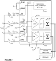
- FIGURE 3 illustrates current leakage present in circuitry that performs a four-wire impedance measurement of bio-impedance, according to some embodiments of the disclosure.
- the current leakage arises because the impedance Z S- of the branch having electrode 108 can be similar to the impedance Z F- of the branch having electrode 110 driving the TIA 128. This results in some of the current I BODY flowing through the unknown bio-impedance Z BODY to flow through the branch having electrode 108, and not all of the current I BODY would flow through the branch having electrode 110.
- the current I ZS- through the branch having electrode 108 is ideally zero, and the current I ZF- through the branch having electrode 110 is ideally equal to current I BODY .
- the current I ZS- is not zero.
- the current I ZF- through the branch having electrode 110 is not equal to current I BODY , and part of current I BODY is not measured by the current measurement circuitry 126.
- the current measurement is corrupted, and thus the impedance measurement is also corrupted. This issue can be exacerbated by high contact impedances in the branches.
- mux 112 By configuring mux 112 and making multiple current measurements, it is possible to derive the (unknown) impedances of the system, including the unknown bio-impedance Z BODY , and the contact impedances Z E1 , Z E2 , Z E3 , and Z E4 , based on a system of equations.
- the system of equations are formed through a calibration measurement, and several other current measurements of different signal paths formed by configuring mux 112.
- Mux 112 can selectively couple the output of the signal generator 116 and the input of the current measurement circuitry 126 to different pins (e.g., RCAL1, RCAL2, CE0, AIN2, AIN3, and AIN1).
- mux 112 can connect the output of the signal generator 116 to the input of the current measurement circuitry 126 through different signal paths, or different impedance networks involving at least some of the unknown impedances.
- the different signal paths individually, can include two or more of the unknown impedances of the system: the unknown bio-impedance Z BODY , and the contact impedances Z E1 , Z E2 , Z E3 , and Z E4 .
- Unique signal paths or unique impedance networks of at least some of the unknown impedances, and the current measurements of the unique signal paths or unique impedance networks setup a system of equations for the unknown impedances.
- the unique signal paths or unique impedance networks together, include each one of the unknown impedances at least once. Each unique signal path or unique impedance network would include at least some of the unknown impedances of the system.
- the signal generator 116 can excite unique signal paths or unique impedance networks formed by mux 112, and the current measurement circuitry 126 can make measurements of current going through the unique signal paths or unique impedance networks.
- the digital circuitry 190 can be provided on-chip with circuitry 150 or off-chip (as shown). Digital circuitry 190 can be implemented to control mux 112 to form unique signal paths or unique impedance networks from the signal generator 116 to the current measurement circuitry 126.
- Computer-readable storage 192 can store the measurements. Computer-readable storage 192 can store the instructions that implement the signal processing. The computer-readable storage 192 can be provided on-chip with circuitry 150 or off-chip (as shown).
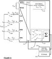
- FIGURE 4 illustrates a calibration measurement, according to some embodiments of the disclosure.
- the calibration measurement is performed to determine a peak voltage from the signal generator 116, if it is not already measured or if it is not already known.
- the system of equations (shown as equations 2-6 below) being formed by the current measurements of unique signal paths going through at least some of the unknown impedances use the peak voltage measured in the calibration measurement as a numerical constant.
- V CAL I CAL ⁇ R CAL (reproduced as equation 1 below).
- R CAL is a resistor with a known stable resistance value.
- I CAL is measured by the current measurement circuitry 126. Accordingly, V CAL , which is the voltage from signal generator 116 can be derived.
- the resistor with a known resistance value can be provided on-chip with circuitry 150 or off-chip (as shown).
- the calibration measurement is optional if the peak voltage from the signal generator is known. The calibration measurement may only need to be performed once, and does not need to be performed every time impedance measurements are being made.
- an (off-chip) resistor R CAL having a known, stable resistance value is coupled across pins RCAL1 and RCAL2.
- the mux 112 is configured to couple the signal path from pin RCAL1 to the signal generator 116 and to couple the signal path from pin RCAL2 to the current measurement circuitry 126.
- the mux 112 forms a signal path from the output of signal generator 116 to input of current measurement circuitry 126, and the signal path includes resistor R CAL .
- the mux 112 connects the output of signal generator 116 to input of current measurement circuitry 126 through the resistor R CAL .
- the measured current performed by current measurement circuitry is I CAL .
- the measured current I CAL and the known resistance value of resistor R CAL form equation 1, seen below.
- the voltage V CAL represents the (calibrated) peak voltage from signal generator 116.
- the measurement of the voltage V CAL across R CAL is determined by measuring a current through R CAL , i.e., through the signal path that includes R CAL , by current measurement circuitry 126.
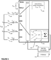
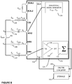
- FIGURES 5-9 illustrate five current measurements, according to embodiments of the disclosure.
- the five current measurements setup a system of five equations, and the five unknown impedances (the bio-impedance and the four contact impedances) can be derived from solving the system of five equations.
- impedances in a cable connected to a pin and a contact impedance are lumped together and represented as a contact impedance (e.g., Z E1 , Z E2 , Z E3 , and Z E4 ), for simplicity.
- the contact impedances thus represent individual branch impedances.
- the mux 112 is configured to couple the signal path from pin CE0 to the output of the signal generator 116 and to couple the signal path from pin AlN1 to the input of the current measurement circuitry 126.
- the measured current obtained by current measurement circuitry 126 is I 1 .
- the measured current I 1 , measured current I CAL , and the known resistance value of R CAL form equation 2, seen below.
- Mux 112 has formed a signal path from the signal generator 116 to the current measurement circuitry 126.
- the signal path includes unknown contact impedance Z E1 , unknown bio-impedance Z BODY , and unknown contact impedance Z E4 (in series).
- the signal path includes a branch with electrode 104 and pin CE0, and a branch with electrode 110 and pin AIN1.
- Equation 2 encapsulates the relationship between the three unknown impedances Z E1 , Z BODY , and Z E4 in the signal path and the measured current I 1 , measured current I CAL , and the known resistance value of R CAL . Note that the product of the measured current I CAL and the known resistance value of R CAL is equivalent to the voltage V CAL obtained from the calibration measurement.
- the mux 112 is configured to couple the signal path from pin CE0 to the output of the signal generator 116 and to couple the signal path from pin AIN2 to the input of the current measurement circuitry 126.
- the measured current obtained by current measurement circuitry 126 is I 2 .
- the measured current I 2 , measured current I CAL , and the known resistance value of R CAL form equation 3, seen below.
- Mux 112 has formed a signal path from the signal generator 116 to the current measurement circuitry 126.
- the signal path includes unknown contact impedance Z E1 and unknown contact impedance Z E2 (in series).
- the signal path includes a branch with electrode 104 and pin CE0, and a branch with electrode 106 and pin AIN2. Equation 3 encapsulates the relationship between the two unknown impedances Z E1 and Z E2 in the signal path and the measured current I 2 , measured current I CAL , and the known resistance value of R CAL .
- the mux 112 is configured to couple the signal path from pin CE0 to the output of the signal generator 116 and to couple the signal path from pin AIN3 to the input of the current measurement circuitry 126.
- the measured current obtained by current measurement circuitry 126 is I 3 .
- the measured current I 3 , measured current I CAL , and the known resistance value of R CAL form equation 4, seen below.
- Mux 112 has formed a signal path from the signal generator 116 to the current measurement circuitry 126.
- the signal path includes unknown contact impedance Z E1 , unknown bio-impedance Z BODY , and unknown contact impedance Z E3 (in series).
- the signal path includes a branch with electrode 104 and pin CE0, and a branch with electrode 108 and pin AIN3. Equation 4 encapsulates the relationship between the three unknown impedances Z E1 , Z BODY , and Z E3 in the signal path and the measured current I 3 , measured current I CAL , and the known resistance value of R CAL
- the mux 112 is configured to couple the signal path from pin AIN2 to the output of the signal generator 116 and to couple the signal path from pin AIN1 to the input of the current measurement circuitry 126.
- the measured current obtained by current measurement circuitry 126 is I 4 .
- the measured current I 4 , measured current I CAL , and the known resistance value of R CAL form equation 5, seen below.
- Mux 112 has formed a signal path from the signal generator 116 to the current measurement circuitry 126.
- the signal path includes unknown contact impedance Z E2 , unknown bio-impedance Z BODY , and unknown contact impedance Z E4 (in series).
- the signal path includes a branch with electrode 106 and pin AIN2, and a branch with electrode 110 and pin AIN1. Equation 5 encapsulates the relationship between the three unknown impedances Z E2 , Z BODY , and Z E4 in the signal path and the measured current I 4 , measured current I CAL , and the known resistance value of R CAL
- the mux 112 is configured to couple the signal path from pin AIN3 to the output of the signal generator 116 and to couple the signal path from pin AIN1 to the input of the current measurement circuitry 126.
- the measured current obtained by current measurement circuitry 126 is I 5 .
- the measured current I 5 , measured current I CAL , and the known resistance value of R CAL form equation 6, seen below.
- Mux 112 has formed a signal path from the signal generator 116 to the current measurement circuitry 126.
- the signal path includes unknown contact impedance Z E3 and unknown contact impedance Z E4 (in series).
- the signal path includes a branch with electrode 108 and pin AIN3, and a branch with electrode 110 and pin AIN1.
- Equation 6 encapsulates the relationship between the two unknown impedances, Z E3 and Z E4 , in the signal path and the measured current I 5 , measured current I CAL , and the known resistance value of R CAL .
- each unique signal path includes two branch impedances.
- some of the unique signal paths can each include the bio-impedance and two branch impedances.
- Each unique signal path includes at least some of the unknown impedances, and together, the unique signal paths include each unknown impedance at least once.
- Equations 2-6) can be rewritten to equations 7-11 that gives the unknown impedances Z BODY , Z E1 , Z E2 , Z E3 , and Z E4 in terms of one or more ones of the current measurements (one or more of I 1 , I 2 , I 3 , I 4 , and I 5 ), the measured current I CAL , and the known resistance value of R CAL .
- Digital circuitry 190 such as a microcontroller or microprocessor, can be implemented to compute the unknown impedances based on the measurements seen in FIGURES 4-9 and equations 7-11.
- Computer-readable storage 192 can store the measurements, and instructions for processing the measurements to derive the impedances.
- Z E 1 I CAL ⁇ R CAL 2 ⁇ 1 I 1 + 1 I 2 ⁇ 1 I 4 (eq. 7)
- Z E 2 I CAL ⁇ R CAL 2 ⁇ 1 I 2 + 1 I 4 ⁇ 1 I 1 (eq. 8)
- Z E 3 I CAL ⁇ R CAL 2 ⁇ 1 I 3 + 1 I 5 ⁇ 1 I 1 (eq. 9)
- Z E 4 I CAL ⁇ R CAL 2 ⁇ 1 I 1 + 1 I 5 ⁇ 1 I 3 (eq. 10)
- Z BODY I CAL ⁇ R CAL 2 ⁇ 1 I 3 + 1 I 4 ⁇ 1 I 2 ⁇ 1 I 5 (eq. 11)
- the measurements seen in FIGURES 4-9 can be performed in any order. In some cases, more than five measurements can be made to generate more than five equations.
- FIGURES 4-9 can have several advantages. Note that a voltage measurement across the unknown bio-impedance Z BODY is no longer needed (which is normally required in the four-wire impedance measurement illustrated by FIGURE 1 ). As a result, an expensive inAmp 120 is no longer required in circuitry 150. Furthermore, the error due to the grounded capacitances at pins AIN2 and AIN3 (acting as a low pass filter), which causes the voltages of V A not being the same as V C and the voltages of V B not being the same as V D , is no longer relevant since a voltage measurement is not being made. Moreover, the scheme can effectively derive five impedances Z BODY , Z E1 , Z E2 , Z E3 , and Z E4 .
- FIGURE 10 illustrates current leakage present in the measurement seen in FIGURE 5 , according to some embodiments of the disclosure.
- current I 1 current (as illustrated by FIGURE 5 )
- the branches which are not connected to the signal generator 116 or the current measurement circuitry 126 ideally has infinite impedance. With infinite impedance, the branches which are not connected to the signal generator 116 or the current measurement circuitry 126 would have zero current.
- I ZE2 current through branch having electrode 106 and pin Ain2
- I ZE3 current through branch having electrode 108 and pin AIN3 are ideally zero.
- the branches which are not connected to the signal generator 116 or the current measurement circuitry 126 do not have infinite impedances, and can have grounded capacitances 1002 and 1004 (e.g., in the pF or ⁇ F range).
- the grounded capacitances 1002 and 1004 represent circuitry (e.g., circuitry in mux 112) capable of sinking current in the branches.
- a part of the current I ZE1 may flow through the branches which are not connected to the signal generator 116 or the current measurement circuitry 126.
- I ZE2 and I ZE3 is not zero, and I ZE1 may not be equal to I BODY , and may not be equal to I TIA .
- current is leaking through the branches having electrode 106 and electrode 108, and the current measurement circuitry 126 is measuring the current through the unknown bio-impedance Z BODY inaccurately (I TIA ⁇ I BODY ).
- the current measurements setting up a system of equations having the unknown impedances can be modified.
- the configuration of the mux 112 is adapted for each measurement, and a different system of equations is used for deriving the unknown impedances.
- all signal paths are connected either to the signal generator 116 or the current measurement circuitry 126.
- the unique signal paths or unique impedance networks instead of each including just a subset of the unknown impedances or just two of four branches, the unique signal paths or unique impedance networks would include all of the bio-impedance and the branch impedances, and all four branches. As a result, leaked current can be captured by the system of equations.
- one of the signal paths is connected to the signal generator 116, and the other three of the signal paths are connected to the current measurement circuitry 126.
- One of the four branches is connected to the output of signal generator 116, and three other ones of the four branches are connected to the input of current measurement circuitry 126.
- two signal paths are connected to the signal generator 116, and the other two of the signal paths are connected to the current measurement circuitry 126.
- Two of the four branches are connected to the output of signal generator 116, and two other ones of the four branches are connected to the input of current measurement circuitry 126. Accordingly, no floating branches will cause current leakage or sink current.
- the five current measurements form a different system of equations, since the overall signal path formed by the mux 112 from the signal generator 116 to the current measurement circuitry 126 now involves parallel impedances (i.e., parallel unknown impedances). However, the system of equations having five equations can still enable the five unknown impedances to be determined.
- mux 112 By configuring mux 112 and making multiple current measurements, it is possible to derive the unknown impedances of the system, including the unknown bio-impedance Z BODY , and the contact impedances Z E1 , Z E2 , Z E3 , and Z E4 , based on a system of equations.
- the system of equations are formed through a calibration measurement, and several current measurements of different, unique signal paths formed by configuring mux 112.
- Mux 112 can selectively couple the output of the signal generator 116 and the input of the current measurement circuitry 126 to different pins (e.g., RCAL1, RCAL2, CE0, AIN2, AIN3, and AIN1).
- mux 112 can connect the output of the signal generator 116 to the input of the current measurement circuitry 126 through different signal paths, or different impedance networks involving all of the unknown impedances.
- the different, unique signal paths form unique impedance networks, where each unique impedance network combines all of the unknown impedances of the system: the unknown bio-impedance Z BODY , and the contact impedances Z E1 , Z E2 , Z E3 , and Z E4 , with a unique topology.
- Unique signal paths or unique impedance networks each involving all of the unknown impedances, and the current measurements of the unique signal paths or unique impedance networks setup a system of equations for the unknown impedances.
- the signal generator 116 can excite unique signal paths or unique impedance networks formed by mux 112, and the current measurement circuitry 126 can make measurements of current going through the unique signal paths or unique impedance networks.
- the bio-impedance and the four contact impedances At least five equations are needed. With a sufficient number of equations, it is possible to derive the five unknown impedances through signal processing (i.e., calculations).
- the current measurements allow the bio-impedance and the contact impedances to be determined.
- the current measurements can be performed by the current measurement circuitry 126.
- the signal processing can be performed in the digital domain, e.g., by digital circuitry 190.
- Digital circuitry 190 can include specialized digital hardware to perform the signal processing.
- Digital circuitry 190 can include a microprocessor or microcontroller configured to carry out instructions that implement the signal processing.
- the digital circuitry 190 can be provided on-chip with circuitry 150 or off-chip (as shown). Digital circuitry 190 can be implemented to control mux 112 to form unique signal paths or unique impedance networks from the signal generator 116 to the current measurement circuitry 126.
- Computer-readable storage 192 can store the measurements. Computer-readable storage 192 can store the instructions that implement the signal processing. The computer-readable storage 192 can be provided on-chip with circuitry 150 or off-chip (as shown).
- FIGURES 11-15 illustrate five current measurements, according to embodiments of the disclosure.
- the five current measurements setup a system of five equations, and the five unknown impedances (the bio-impedance and the four contact impedances) can be derived from solving the system of five equations.
- impedances in a cable connected to a pin is lumped together and represented as a contact impedance (e.g., Z E1 , Z E2 , Z E3 , and Z E4 ), for simplicity.
- the contact impedances thus represent individual branch impedances.
- the mux 112 is configured to couple the signal path from pin CE0 to the output of the signal generator 116, to couple the signal path from pin AIN2 to the input of current measurement circuitry 126, to couple the signal path from pin AIN3 to the input of current measurement circuitry 126, to couple the signal path from pin AIN1 to the input of current measurement circuitry 126.
- the measured current done by current measurement circuitry 126 is I 1 .
- the configuration of mux 112 in FIGURE 11 forms an overall signal path that includes Z E1 in series with (Z E2 in parallel with (Z BODY in series with (Z E3 and Z E4 in parallel)).
- the branch with electrode 104 and pin CE0 is connected to the output of the signal generator 116.
- the branch with electrode 106 and pin AIN2 is connected to the input of current measurement circuitry 126.
- the branch with electrode 108 and pin AIN3 is connected to the input of current measurement circuitry 126.
- the branch with electrode 110 and pin AIN1 is connected to the input of current measurement circuitry 126.
- the measured current I 1 , measured voltage V CAL form equation 12, seen below. Equation 12 encapsulates the relationship between the measured current I 1 , measured voltage V CAL , and the unknown impedances in the overall signal path from the signal generator 116 to current measurement circuitry 126 (formed by the mux 112 in the configuration shown in FIGURE 11 ).
- the mux 112 is configured to couple the signal path from pin AIN2 to the output of signal generator 116, to couple the signal path from pin CE0 to the input of current measurement circuitry 126, to couple the signal path from pin AIN3 to the input of current measurement circuitry 126, to couple the signal path from pin AIN1 to the input of current measurement circuitry 126.
- the measured current done by current measurement circuitry 126 is I 2 .
- the configuration of mux 112 in FIGURE 12 forms an overall signal path that includes Z E2 in series with (Z E1 in parallel with (Z BODY in series with (Z E3 and Z E4 in parallel))).
- the branch with electrode 104 and pin CE0 is connected to the input of the current measurement circuitry 126.
- the branch with electrode 106 and pin AIN2 is connected to the output of signal generator 116.
- the branch with electrode 108 and pin AIN3 is connected to the input of current measurement circuitry 126.
- the branch with electrode 110 and pin AIN1 is connected to the input of current measurement circuitry 126.
- the measured current I 2 , measured voltage V CAL form equation 13, seen below. Equation 13 encapsulates the relationship between the measured current I 2 , measured voltage V CAL , and the unknown impedances in the overall signal path from the signal generator 116 to current measurement circuitry 126 (formed by the mux 112 in the configuration shown in FIGURE 12 ).
- the mux 112 is configured to couple the signal path from pin AIN3 to the output of signal generator 116, to couple the signal path from pin CE0 to the input of current measurement circuitry 126, to couple the signal path from pin AIN2 to the input of current measurement circuitry 126, to couple the signal path from pin AIN1 to the input of current measurement circuitry 126.
- the measured current done by current measurement circuitry 126 is I 3 .
- the configuration of mux 112 in FIGURE 13 forms an overall signal path that includes Z E3 in series with (Z E4 in parallel with (Z BODY in series with (Z E1 and Z E2 in parallel))).
- the branch with electrode 104 and pin CE0 is connected to the input of the current measurement circuitry 126.
- the branch with electrode 106 and pin AIN2 is connected to input of the current measurement circuitry 126.
- the branch with electrode 108 and pin AIN3 is connected to the output of signal generator 116.
- the branch with electrode 110 and pin AIN1 is connected to the input of current measurement circuitry 126.
- the measured current I 3 , measured voltage V CAL form equation 14, seen below. Equation 14 encapsulates the relationship between the measured current I 3 , measured voltage V CAL , and the unknown impedances in the overall signal path from the signal generator 116 to current measurement circuitry 126 (formed by the mux 112 in the configuration shown in FIGURE 13 ).
- the mux 112 is configured to couple the signal path from pin AIN1 to the signal generator 116, to couple the signal path from pin CE0 to the current measurement circuitry 126, to couple the signal path from pin AIN2 to the current measurement circuitry 126, to couple the signal path from pin AIN3 to the current measurement circuitry 126.
- the measured current done by current measurement circuitry 126 is I 4 .
- the configuration of mux 112 in FIGURE 14 forms an overall signal path that includes Z E4 in series with (Z E3 in parallel with (Z BODY in series with (Z E1 and Z E2 in parallel))).
- the branch with electrode 104 and pin CE0 is connected to the input of the current measurement circuitry 126.
- the branch with electrode 106 and pin AIN2 is connected to input of the current measurement circuitry 126.
- the branch with electrode 108 and pin AIN3 is connected to the input of current measurement circuitry 126.
- the branch with electrode 110 and pin AIN1 is connected to the output of signal generator 116.
- the measured current I 4 , measured voltage V CAL form equation 15, seen below. Equation 15 encapsulates the relationship between the measured current I 4 , measured voltage V CAL , and the unknown impedances in the overall signal path from the signal generator 116 to current measurement circuitry 126 (formed by the mux 112 in the configuration shown in FIGURE 14 ).
- the mux 112 is configured to couple the signal path from pin CE0 to the signal generator 116, to couple the signal path from pin AIN2 to the signal generator 116 (as well), to couple the signal path from pin AIN3 to the current measurement circuitry 126, to couple the signal path from pin AIN1 to the current measurement circuitry 126.
- the measured current done by current measurement circuitry 126 is I 5 .
- the configuration of mux 112 in FIGURE 15 forms an overall signal path that includes (Z E1 and Z E2 in parallel) in series with Z BODY and in series with (Z E3 and Z E4 in parallel).
- the branch with electrode 104 and pin CE0 is connected to the output of the output of signal generator 116.
- the branch with electrode 106 and pin AIN2 is connected to the output of the output of signal generator 116.
- the branch with electrode 108 and pin AIN3 is connected to the input of current measurement circuitry 126.
- the branch with electrode 110 and pin AIN1 is connected to the input of current measurement circuitry 126.
- the measured current I 5 , measured voltage V CAL form equation 16, seen below. Equation 16 encapsulates the relationship between the measured current I 5 , measured voltage V CAL , and the unknown impedances in the overall signal path from the signal generator 116 to current measurement circuitry 126 (formed by the mux 112 in the configuration shown in FIGURE 15 ).
- FIGURE 15 An alternative to the signal path illustrated by FIGURE 15 is to connect the branch with electrode 104 and pin CE0 and the branch with electrode 106 and pin AIN2 is connected to the input of current measurement circuitry 126, and to connect the branch with electrode 108 and pin AIN3 and the branch with electrode 110 and pin AIN1 to the output of signal generator 116.
- I 2 V CAL Z E 2 + Z E 1 / / Z BODY + Z E 3 / / Z E 4 (eq.
- Equations 17-21 show equations 12-16 in an expanded form based on the notation for parallel impedances.
- each unique signal path includes all of the unknown impedances.
- some of the unique signal paths can each include the bio-impedance and two branch impedances.
- Each unique signal path includes at least some of the unknown impedances, and together, the unique signal paths include each unknown impedance at least once.
- Algebraic manipulations can be applied to equations 17-21 to rewrite equations 12-21 so that the unknown impedances Z BODY , Z E1 , Z E2 , Z E3 , and Z E4 are defined in terms of the current measurements (e.g., I 1 , I 2 , I 3 , I 4 , and I 5 ), the measured current I CAL , and the known resistance value of R CAL .
- the following pseudocode can be implemented in digital circuitry 190, such as a microcontroller or microprocessor, to determine and compute the unknown impedances based on the measurements seen in FIGURES 4 , and 11-15 .
- the measurements seen in FIGURES 4 , and 11-15 can be performed in any order. In some cases, more than five measurements can be made to generate more than five equations.
- FIGURES 4 , and 11-15 can have several advantages (similar to the scheme seen in FIGURES 4-9 ). Note that a voltage measurement across the unknown bio-impedance Z BODY is no longer needed (which is normally required in the four-wire impedance measurement illustrated by FIGURE 1 ). As a result, an expensive inAmp 120 is no longer required in circuitry 150. Furthermore, the error due to the grounded capacitances at pins AIN2 and AIN3 (acting as a low pass filter), which causes to the voltages of V A not being the same as V C and the voltages of V B not being the same as V D , is no longer relevant since a voltage measurement is not being made.
- the scheme can effectively and accurately derive five impedances Z BODY , Z E1 , Z E2 , Z E3 , and Z E4 .
- this scheme can now ensure accuracy even in the presence of high impedances, and big imbalances between contact impedances.
- Measuring bio-impedance can be particularly useful for measuring body impedance for detecting fluid level of the lungs or measuring thoracic impedance. Measuring bio-impedance can also be useful in electrical impedance tomography to determine a composition of the body (e.g., imaging of tissues and bones) in a non-invasive manner by making bio-impedance measurements at different frequencies. Measuring bio-impedance can be useful in measuring respiration activity, where respiration activity can be obtained by observing variation in thorax impedance. Measuring bio-impedance and the contact impedances means that respiration activity can be obtained even in the presence of motion, since variations in contact impedances can be taken into account. Users such as athletes and patients can greatly benefit from such applications.
- Knowing the contact impedances Z E1 , Z E2 , Z E3 , and Z E4 in addition to the unknown bio-impedance Z BODY can enable the circuitry to infer whether the contacts (i.e., contacts being formed by the electrodes contacting the body) are good or not, e.g., as part of a diagnostic process. For instance, high contact impedances can indicate that patches/electrodes are not properly attached to the body. Accordingly, information about the quality of the contacts can be inferred from derived contact impedances.
- the digital circuitry 190 can determine quality of contacts corresponding to the four electrodes based on the impedances of the four branches. If a given impedance of a branch is too high, the digital circuitry 190 can infer that the contact for the branch is bad and output a signal that indicates the presence of a bad contact and optionally an identifier that identifies which contact is bad. The digital circuitry 190 can compare the impedances of the four branches against predetermined threshold(s) to determine whether a given impedance is too high.
- User feedback can be provided based on the inferred information about the quality of the contacts.
- smart drug delivery applications may require proper contacts to the body to ensure correct and effective drug delivery. If the contact is improper, drug can pool on the skin due to poor absorption and contact to the skin.
- Other applications such as electrocardiography or defibrillation, may also require proper contacts to the body. Being able to infer the quality of the contacts based on the derived contact impedances can provide feedback to the user regarding the quality of the contacts in such contexts as well.
- the impedances measurement schemes described herein can be used in a variety of situations. For instance, the impedances measurement scheme can be used to, non-invasively, obtain the body's composition, determine thoracic impedance, determine respiration activity in the presence of motion, etc.
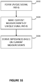
- FIGURE 16 is a flow diagram illustrating a method for measuring impedances, according to some embodiments of the disclosure.
- the impedances include a bio-impedance and four branch impedances.
- circuitry such as mux 112 can form unique signal paths.
- current measurement circuitry 126 can make current measurements of the unique signal paths.
- the unique signal paths setup a system of equations that enables the impedances to be derived. To ensure the system of equations would yield the unknown impedances, each unique signal path includes at least some of the impedances, the unique signal paths include each impedance at least once.
- digital circuitry 190 can derive the impedances based on the current measurements.
- certain embodiments discussed above can be provisioned in digital signal processing technologies for medical imaging, patient monitoring, medical instrumentation, and home healthcare.
- the embodiments herein can also be beneficial to other applications requiring an accurate impedance measurement using at least four electrodes.
- Parts of various circuitry for deriving unknown impedances can include electronic circuitry to perform the functions described herein.
- one or more parts of the circuitry can be provided by a processor specially configured for carrying out the functions described herein.
- the processor may include one or more application specific components, or may include programmable logic gates which are configured to carry out the functions describe herein.
- the circuitry can operate in analog domain, digital domain, or in a mixed signal domain.
- the processor may be configured to carrying out the functions described herein by executing one or more instructions stored on a non-transitory computer medium.
- an apparatus can include means for performing or implementing one or more of the functionalities describe herein.
- references to various features e.g., elements, structures, modules, components, steps, operations, characteristics, etc.
- references to various features e.g., elements, structures, modules, components, steps, operations, characteristics, etc.
- references to various features are intended to mean that any such features are included in one or more embodiments of the present disclosure, but may or may not necessarily be combined in the same embodiments.
Landscapes
- Health & Medical Sciences (AREA)
- Life Sciences & Earth Sciences (AREA)
- Physics & Mathematics (AREA)
- Engineering & Computer Science (AREA)
- Pathology (AREA)
- General Health & Medical Sciences (AREA)
- Veterinary Medicine (AREA)
- Animal Behavior & Ethology (AREA)
- Biomedical Technology (AREA)
- Heart & Thoracic Surgery (AREA)
- Medical Informatics (AREA)
- Molecular Biology (AREA)
- Surgery (AREA)
- Biophysics (AREA)
- Public Health (AREA)
- Nuclear Medicine, Radiotherapy & Molecular Imaging (AREA)
- General Physics & Mathematics (AREA)
- Radiology & Medical Imaging (AREA)
- Chemical & Material Sciences (AREA)
- Signal Processing (AREA)
- Physiology (AREA)
- Pulmonology (AREA)
- Biochemistry (AREA)
- Analytical Chemistry (AREA)
- Immunology (AREA)
- Electrochemistry (AREA)
- Chemical Kinetics & Catalysis (AREA)
- Dermatology (AREA)
- Power Engineering (AREA)
- Artificial Intelligence (AREA)
- Computer Vision & Pattern Recognition (AREA)
- Psychiatry (AREA)
- Measurement And Recording Of Electrical Phenomena And Electrical Characteristics Of The Living Body (AREA)
- Measurement Of Resistance Or Impedance (AREA)
Abstract
Description
- This patent application claims priority to and receives benefit from
US Provisional Application, Serial No. 62/678,986 US Provisional Application, Serial No. 62/679,460 - The present invention relates to the field of integrated circuits, in particular to impedance measurements.
- Impedance measurements of the body, referred herein as bio-impedance, has many applications in healthcare and consumer applications. Impedance measurements can be made by electrodes provided in body-worn systems, or wearable devices, such as wrist watches, chest bands, head bands, patches, and so on. Circuitry coupled to the electrodes can derive the unknown impedance of the body on which the electrodes are placed. Impedance measurements can be particularly useful for vital-signs monitoring, sensing of tissues and fluid level in the body for purposes of detecting signs of pulmonary edema, or assess body composition. Moreover, electrical impedance tomography is an emerging non-invasive technique of medical imaging. Due to various challenges, making an accurate bio-impedance measurement is not trivial.
- To provide a more complete understanding of the present disclosure and features and advantages thereof, reference is made to the following description, taken in conjunction with the accompanying figures, wherein like reference numerals represent like parts, in which:
-
FIGURE 1 illustrates a system having electrodes and circuitry for performing one exemplary way of making a four-wire impedance measurement of bio-impedance, according to some embodiments of the disclosure; -
FIGURE 2 illustrates input capacitances present in circuitry that performs a four-wire impedance measurement of bio-impedance, according to some embodiments of the disclosure; -
FIGURE 3 illustrates current leakage present in circuitry that performs a four-wire impedance measurement of bio-impedance, according to some embodiments of the disclosure; -
FIGURE 4 illustrates a calibration measurement, according to some embodiments of the disclosure; -
FIGURES 5-9 illustrate five current measurements, according to embodiments of the disclosure; -
FIGURE 10 illustrates current leakage present in the measurement seen inFIGURE 5 , according to some embodiments of the disclosure; -
FIGURES 11-15 illustrate five current measurements which avoid current leakage, according to embodiments of the disclosure; and -
FIGURE 16 is a flow diagram illustrating a method for measuring impedances, according to some embodiments of the disclosure. - Accurately measuring bio-impedance is important for sensing properties of the body. Unfortunately, contact impedances can significantly degrade the accuracy of bio-impedance measurements. To address this issue, circuitry for implementing a four-wire impedance measurement can be configured to make multiple current measurements. The multiple current measurements set up a system of equations to allow the unknown bio-impedance and contact impedances to be derived. The result is an accurate bio-impedance measurement that is not negatively impacted by large contact impedances. Moreover, bad contacts with undesirably large impedances can be identified.
- One technique for impedance measurement is a four-terminal sensing scheme, or four-wire impedance measurement scheme. Sometimes it is referred to as Kelvin sensing. The technique involves using four electrodes placed on the body to sense or derive an unknown bio-impedance.
-
FIGURE 1 illustrates asystem 100 having electrodes and circuitry for performing one exemplary way making a four-wire impedance measurement of bio-impedance, according to some embodiments of the disclosure. In the FIGURE, the unknown bio-impedance is shown as ZBODY. Thesystem 100 includeselectrodes electrodes electrodes Circuitry 150, packaged as an integrated circuit or chip, has pins (or connections) to which the electrodes are connected. Pin CE0 is electrically coupled toelectrode 104. Pin AIN2 is electrically coupled toelectrode 106. Pin AIN3 is electrically coupled toelectrode 108. Pin AIN1 is electrically coupled toelectrode 110. - The
system 100 has four branches: a branch that includeselectrode 104 and pin CE0, a branch that includeselectrode 106 and pin AIN2, a branch that includeselectrode 108 and pin AIN3, and a branch that includeselectrode 110 and pin AIN1. Two branches are for sensing a first end of the unknown bio-impedance ZBODY, and two other branches are for sensing a second end of the unknown bio-impedance ZBODY. The branch that includeselectrode 104 is coupled to the first end of unknown bio-impedance ZBODY. The branch that includeselectrode 106 is coupled to the first end of unknown bio-impedance ZBODY. The branch that includeselectrode 108 is coupled to the second end of unknown bio-impedance ZBODY. The branch that includeselectrode 110 is coupled to the second end of unknown bio-impedance ZBODY. The four branches are connected to respective pins ofcircuitry 150. Parts of the branches outside ofcircuitry 150 can represent cables with patches at the end of the cables. Parts of the branches outside ofcircuitry 150 can also represent conductors or wires having electrodes at the end of the conductors or wires. The conductors and electrodes can be fitted in a wearable device. Optionally, capacitances shown CISO1, CISO2, CISO3, CISO4 can be included between respective pairs of electrodes and pins to provide isolation and protection between the body of the human user and the circuitry within circuitry 150 (e.g., to block DC signals). -
Circuitry 150 can include a multiplexer (mux) 112.Mux 112 can be controlled in a manner to connect signal paths of the different pins to different parts ofcircuitry 150.Mux 112, as used herein, represents a configurable network controllable to connect different parts ofcircuitry 150 to different pins. For instance,mux 112 can connect different parts ofcircuitry 150 to different branches connected to the pins (the branches having respective electrodes). Different configurations ofmux 112 can form different signal paths or different impedance networks (impedance networks being synonymous with signal paths). -
Circuitry 150 can include a signal generator 116 (e.g., sinusoidal signal generator). Signal generator can generate a signal having a peak voltage of VPEAK. The signal generator generates the signal at an output of the signal generator. -
Circuitry 150 can includevoltage measurement circuitry 118 to measure a voltage across a positive input and a negative input of thevoltage measurement circuitry 118. In some embodiments,voltage measurement circuitry 118 can include an instrumentation amplifier (inAmp) 120 with a positive terminal and a negative terminal to sense a voltage difference between the positive terminal and negative terminal, and outputs a voltage output representative of that voltage difference.Voltage measurement circuitry 118 can include a Discrete Fourier Transform (DFT)block 122 andsummation block 124 to generate a voltage measurement based on the voltage output frominAmp 120. Components for generating a voltage measurement (e.g., a difference in voltage between two inputs) can differ depending on the implementation. -
Circuitry 150 can further includecurrent measurement circuitry 126 to measure a current at an input of thecurrent measurement circuitry 126. In some embodiments,current measurement circuitry 126 can include a transimpedance amplifier (TIA) 128 to convert a current at an input terminal of theTIA 128 to a voltage output representative of the current.Current measurement circuitry 126 can include aDFT block 130 and summation block 132 to generate a current measurement based on the voltage output fromTIA 128. Components for generating a current measurement (e.g., an amount of current flowing through an input) can differ depending on the implementation. - To make an impedance measurement, a voltage is generated across the unknown bio-impedance shown as ZBODY. The voltage across the unknown bio-impedance ZBODY can be viewed as VA-VB. The voltage across the unknown bio-impedance ZBODY can be generated or imposed by
signal generator 116. Meanwhile, the voltage across the unknown bio-impedance ZBODY is measured by thevoltage measurement circuitry 118, and the current through the unknown bio-impedance ZBODY is also measured, bycurrent measurement circuitry 126. The measured voltage and the measured current can be used to derive the impedance value of the unknown bio-impedance ZBODY. Specifically, the impedance value of the unknown bio-impedance ZBODY is related to the voltage measurement divided by the current measurement. - In conventional two-wire impedance measurements, measurement issues can arise from impedances of cables (including contact impedances) being added to the unknown bio-impedance ZBODY, thus corrupting the impedance measurement. For simplicity, the impedances present are lumped together as a contact impedance in each branch. In theory, a four-wire impedance measurement can avoid such issues. When the unknown bio-impedance ZBODY is much higher than the impedances of the cables, the measurements can be sufficiently accurate.
- However, in practice, a four-wire impedance measurement can have certain other limitations or non-idealities that can significantly impact the accuracy of the bio-impedance measurement. These limitations can be significant, e.g., when making impedance measurements at low frequencies, high frequencies, certain frequencies, or various frequencies. In some situations, one or more of the contact impedances ZE1, ZE2, ZE3, and ZE4 can be greater than the unknown bio-impedance ZBODY. For instance, mechanical and/or environmental reasons (e.g., humidity, movement, hair on skin, etc.) can cause poor contacts, and can severely increase one or more of the contact impedances. In some severe cases, the (magnitude of) contact impedances can be greater than 2 kΩ. In some situations, the optional capacitors CISO1, CISO2, CISO3, CISO4 can also significantly increase or affect the impedances of the cables. In some situations, the contact impedances ZE1, ZE2, ZE3, and ZE4 can have an imbalance with each other (e.g., imbalance can be greater than 1 kΩ). These limitations have been found to degrade the accuracy of the four-wire impedance measurement.
- One of the problems causing these limitations that degrade the accuracy of the bio-impedance measurement is that there can be large input capacitances at pin AIN2 and pin AIN3 (e.g., around 40 pF).
FIGURE 2 illustrates input capacitances present in circuitry that performs a four-wire impedance measurement of bio-impedance, according to some embodiments of the disclosure.Grounded input capacitance 202 can be present at pin AIN2, and groundedinput capacitance 204 can also be present at pin AIN3.Grounded input capacitance 202, contact impedance ZE2, and capacitance CISO2 can form a filter. This filter can be problematic because the contact impedance ZE2 is unknown, and thus the effect of the filter is unknown as well.Grounded input capacitance 204, contact impedance ZE3, and capacitance CISO3 can also form another filter. This other filter can be problematic because the contact impedance ZE3 is unknown, and thus the effect of this other filter is unknown as well. Ideally, voltage VA should be the same as the voltage VC, and voltage VB should be the same as the voltage VD. Due to the groundedinput capacitances input capacitances input capacitances - Another problem that may degrade the accuracy of the bio-impedance measurement is current leakage.
FIGURE 3 illustrates current leakage present in circuitry that performs a four-wire impedance measurement of bio-impedance, according to some embodiments of the disclosure. The current leakage arises because the impedance ZS- of thebranch having electrode 108 can be similar to the impedance ZF- of thebranch having electrode 110 driving theTIA 128. This results in some of the current IBODY flowing through the unknown bio-impedance ZBODY to flow through thebranch having electrode 108, and not all of the current IBODY would flow through thebranch having electrode 110. In other words, the current IZS- through thebranch having electrode 108 is ideally zero, and the current IZF-through thebranch having electrode 110 is ideally equal to current IBODY. In reality, the current IZS- is not zero. As a result, the current IZF- through thebranch having electrode 110 is not equal to current IBODY, and part of current IBODY is not measured by thecurrent measurement circuitry 126. The current measurement is corrupted, and thus the impedance measurement is also corrupted. This issue can be exacerbated by high contact impedances in the branches. - By configuring
mux 112 and making multiple current measurements, it is possible to derive the (unknown) impedances of the system, including the unknown bio-impedance ZBODY, and the contact impedances ZE1, ZE2, ZE3, and ZE4, based on a system of equations. The system of equations are formed through a calibration measurement, and several other current measurements of different signal paths formed by configuringmux 112.Mux 112 can selectively couple the output of thesignal generator 116 and the input of thecurrent measurement circuitry 126 to different pins (e.g., RCAL1, RCAL2, CE0, AIN2, AIN3, and AIN1). Accordingly,mux 112 can connect the output of thesignal generator 116 to the input of thecurrent measurement circuitry 126 through different signal paths, or different impedance networks involving at least some of the unknown impedances. The different signal paths, individually, can include two or more of the unknown impedances of the system: the unknown bio-impedance ZBODY, and the contact impedances ZE1, ZE2, ZE3, and ZE4. Unique signal paths or unique impedance networks of at least some of the unknown impedances, and the current measurements of the unique signal paths or unique impedance networks, setup a system of equations for the unknown impedances. The unique signal paths or unique impedance networks, together, include each one of the unknown impedances at least once. Each unique signal path or unique impedance network would include at least some of the unknown impedances of the system. Effectively, thesignal generator 116 can excite unique signal paths or unique impedance networks formed bymux 112, and thecurrent measurement circuitry 126 can make measurements of current going through the unique signal paths or unique impedance networks. - To determine five unknown impedances (the bio-impedance and the four contact impedances), at least five equations are needed. With a sufficient number of equations, it is possible to derive the five unknown impedances through signal processing (i.e., calculations). Through suitable processing, the current measurements allow the bio-impedance and the contact impedances to be determined. The current measurements can be performed by the
current measurement circuitry 126. The signal processing can be performed in the digital domain, e.g., bydigital circuitry 190.Digital circuitry 190 can include specialized digital hardware to perform the signal processing.Digital circuitry 190 can include a microprocessor or microcontroller configured to carry out instructions that implement the signal processing. Thedigital circuitry 190 can be provided on-chip withcircuitry 150 or off-chip (as shown).Digital circuitry 190 can be implemented to controlmux 112 to form unique signal paths or unique impedance networks from thesignal generator 116 to thecurrent measurement circuitry 126. Computer-readable storage 192 can store the measurements. Computer-readable storage 192 can store the instructions that implement the signal processing. The computer-readable storage 192 can be provided on-chip withcircuitry 150 or off-chip (as shown). -
FIGURE 4 illustrates a calibration measurement, according to some embodiments of the disclosure. The calibration measurement is performed to determine a peak voltage from thesignal generator 116, if it is not already measured or if it is not already known. The system of equations (shown as equations 2-6 below) being formed by the current measurements of unique signal paths going through at least some of the unknown impedances use the peak voltage measured in the calibration measurement as a numerical constant. The unknown impedances would be derived based further on the peak voltage measured in the calibration measurement. Determining the peak voltage from thesignal generator 116 can be performed in various ways. An output from thesignal generator 116 can be applied to a resistor with a known resistance value, and thecurrent measurement circuitry 126 can measure a current through the resistor. The calibration measurement is represented by: VCAL = ICAL · RCAL (reproduced as equation 1 below). RCAL is a resistor with a known stable resistance value. ICAL is measured by thecurrent measurement circuitry 126. Accordingly, VCAL, which is the voltage fromsignal generator 116 can be derived. - The resistor with a known resistance value can be provided on-chip with
circuitry 150 or off-chip (as shown). The calibration measurement is optional if the peak voltage from the signal generator is known. The calibration measurement may only need to be performed once, and does not need to be performed every time impedance measurements are being made. - In the example shown, for the calibration measurement, an (off-chip) resistor RCAL having a known, stable resistance value is coupled across pins RCAL1 and RCAL2. The
mux 112 is configured to couple the signal path from pin RCAL1 to thesignal generator 116 and to couple the signal path from pin RCAL2 to thecurrent measurement circuitry 126. Themux 112 forms a signal path from the output ofsignal generator 116 to input ofcurrent measurement circuitry 126, and the signal path includes resistor RCAL. Themux 112 connects the output ofsignal generator 116 to input ofcurrent measurement circuitry 126 through the resistor RCAL. The measured current performed by current measurement circuitry is ICAL. With the known resistance value of the resistor RCAL, it is possible to derive the voltage VCAL = ICAL · RCAL across the resistor RCAL. The measured current ICAL and the known resistance value of resistor RCAL form equation 1, seen below. The voltage VCAL represents the (calibrated) peak voltage fromsignal generator 116. The measurement of the voltage VCAL across RCAL is determined by measuring a current through RCAL, i.e., through the signal path that includes RCAL , bycurrent measurement circuitry 126. -
FIGURES 5-9 illustrate five current measurements, according to embodiments of the disclosure. The five current measurements setup a system of five equations, and the five unknown impedances (the bio-impedance and the four contact impedances) can be derived from solving the system of five equations. Note that, in the individual branches, impedances in a cable connected to a pin and a contact impedance are lumped together and represented as a contact impedance (e.g., ZE1, ZE2, ZE3, and ZE4), for simplicity. The contact impedances thus represent individual branch impedances. - In
FIGURE 5 , themux 112 is configured to couple the signal path from pin CE0 to the output of thesignal generator 116 and to couple the signal path from pin AlN1 to the input of thecurrent measurement circuitry 126. The measured current obtained bycurrent measurement circuitry 126 is I1. The measured current I1, measured current ICAL, and the known resistance value of RCAL form equation 2, seen below.Mux 112 has formed a signal path from thesignal generator 116 to thecurrent measurement circuitry 126. The signal path includes unknown contact impedance ZE1, unknown bio-impedance ZBODY, and unknown contact impedance ZE4 (in series). The signal path includes a branch withelectrode 104 and pin CE0, and a branch withelectrode 110 and pin AIN1. Equation 2 encapsulates the relationship between the three unknown impedances ZE1, ZBODY, and ZE4 in the signal path and the measured current I1, measured current ICAL, and the known resistance value of RCAL. Note that the product of the measured current ICAL and the known resistance value of RCAL is equivalent to the voltage VCAL obtained from the calibration measurement. - In
FIGURE 6 , themux 112 is configured to couple the signal path from pin CE0 to the output of thesignal generator 116 and to couple the signal path from pin AIN2 to the input of thecurrent measurement circuitry 126. The measured current obtained bycurrent measurement circuitry 126 is I2. The measured current I2, measured current ICAL, and the known resistance value of RCAL form equation 3, seen below.Mux 112 has formed a signal path from thesignal generator 116 to thecurrent measurement circuitry 126. The signal path includes unknown contact impedance ZE1 and unknown contact impedance ZE2 (in series). The signal path includes a branch withelectrode 104 and pin CE0, and a branch withelectrode 106 and pin AIN2. Equation 3 encapsulates the relationship between the two unknown impedances ZE1 and ZE2 in the signal path and the measured current I2, measured current ICAL, and the known resistance value of RCAL. - In
FIGURE 7 , themux 112 is configured to couple the signal path from pin CE0 to the output of thesignal generator 116 and to couple the signal path from pin AIN3 to the input of thecurrent measurement circuitry 126. The measured current obtained bycurrent measurement circuitry 126 is I3. The measured current I3, measured current ICAL, and the known resistance value of RCAL form equation 4, seen below.Mux 112 has formed a signal path from thesignal generator 116 to thecurrent measurement circuitry 126. The signal path includes unknown contact impedance ZE1, unknown bio-impedance ZBODY, and unknown contact impedance ZE3 (in series). The signal path includes a branch withelectrode 104 and pin CE0, and a branch withelectrode 108 and pin AIN3. Equation 4 encapsulates the relationship between the three unknown impedances ZE1, ZBODY, and ZE3 in the signal path and the measured current I3, measured current ICAL, and the known resistance value of RCAL. - In
FIGURE 8 , themux 112 is configured to couple the signal path from pin AIN2 to the output of thesignal generator 116 and to couple the signal path from pin AIN1 to the input of thecurrent measurement circuitry 126. The measured current obtained bycurrent measurement circuitry 126 is I4. The measured current I4, measured current ICAL, and the known resistance value of RCAL form equation 5, seen below.Mux 112 has formed a signal path from thesignal generator 116 to thecurrent measurement circuitry 126. The signal path includes unknown contact impedance ZE2, unknown bio-impedance ZBODY, and unknown contact impedance ZE4 (in series). The signal path includes a branch withelectrode 106 and pin AIN2, and a branch withelectrode 110 and pin AIN1. Equation 5 encapsulates the relationship between the three unknown impedances ZE2, ZBODY, and ZE4 in the signal path and the measured current I4, measured current ICAL, and the known resistance value of RCAL. - In
FIGURE 9 , themux 112 is configured to couple the signal path from pin AIN3 to the output of thesignal generator 116 and to couple the signal path from pin AIN1 to the input of thecurrent measurement circuitry 126. The measured current obtained bycurrent measurement circuitry 126 is I5. The measured current I5, measured current ICAL, and the known resistance value of RCAL form equation 6, seen below.Mux 112 has formed a signal path from thesignal generator 116 to thecurrent measurement circuitry 126. The signal path includes unknown contact impedance ZE3 and unknown contact impedance ZE4 (in series). The signal path includes a branch withelectrode 108 and pin AIN3, and a branch withelectrode 110 and pin AIN1. Equation 6 encapsulates the relationship between the two unknown impedances, ZE3 and ZE4, in the signal path and the measured current I5, measured current ICAL, and the known resistance value of RCAL.Calibration Measurement VCAL = ICAL · RCAL (eq.1) Current Measurement ( FIGURE 5 )
(eq. 2) Current Measurement ( FIGURE 6 )
(eq. 3) Current Measurement ( FIGURE 7 )
(eq. 4) Current Measurement ( FIGURE 8 )
(eq. 5) Current Measurement ( FIGURE 9 )
(eq. 6) - With five equations (equations 2-6) and five unknown impedances ZBODY, ZE1, ZE2, ZE3, and ZE4, the values for the five unknown impedances ZBODY, ZE1, ZE2, ZE3, and ZE4 can be derived and determined. As illustrated by
FIGURES 5-9 , each unique signal path includes two branch impedances. Moreover, as seen inFIGURES 5 ,7 , and8 , some of the unique signal paths can each include the bio-impedance and two branch impedances. Each unique signal path includes at least some of the unknown impedances, and together, the unique signal paths include each unknown impedance at least once. - The five equations (equations 2-6) can be rewritten to equations 7-11 that gives the unknown impedances ZBODY, ZE1, ZE2, ZE3, and ZE4 in terms of one or more ones of the current measurements (one or more of I1, I2, I3, I4, and I5), the measured current ICAL, and the known resistance value of RCAL. Digital circuitry 190, such as a microcontroller or microprocessor, can be implemented to compute the unknown impedances based on the measurements seen in
FIGURES 4-9 and equations 7-11. Computer-readable storage 192 can store the measurements, and instructions for processing the measurements to derive the impedances.
(eq. 7) 
(eq. 8) 
(eq. 9) 
(eq. 10) 
(eq. 11) - The measurements seen in
FIGURES 4-9 can be performed in any order. In some cases, more than five measurements can be made to generate more than five equations. - The scheme illustrated by
FIGURES 4-9 can have several advantages. Note that a voltage measurement across the unknown bio-impedance ZBODY is no longer needed (which is normally required in the four-wire impedance measurement illustrated byFIGURE 1 ). As a result, anexpensive inAmp 120 is no longer required incircuitry 150. Furthermore, the error due to the grounded capacitances at pins AIN2 and AIN3 (acting as a low pass filter), which causes the voltages of VA not being the same as VC and the voltages of VB not being the same as VD, is no longer relevant since a voltage measurement is not being made. Moreover, the scheme can effectively derive five impedances ZBODY, ZE1, ZE2, ZE3, and ZE4. - In the previous scheme illustrated by the measurements seen in
FIGURES 4-9 , there is one limitation: current leakage.FIGURE 10 illustrates current leakage present in the measurement seen inFIGURE 5 , according to some embodiments of the disclosure. When making a current measurement, such as current I1 (as illustrated byFIGURE 5 ), the branches which are not connected to thesignal generator 116 or thecurrent measurement circuitry 126 ideally has infinite impedance. With infinite impedance, the branches which are not connected to thesignal generator 116 or thecurrent measurement circuitry 126 would have zero current. In other words, IZE2 (current throughbranch having electrode 106 and pin Ain2) and IZE3 (current throughbranch having electrode 108 and pin AIN3) are ideally zero. As a result, IZE1 would be equal to IBODY (current through the unknown bio-impedance), and would also be equal to ITIA (current through branch). This would mean that no current is leaking through thebranches having electrode 106 andelectrode 108, and thecurrent measurement circuitry 126 is measuring the current through the unknown bio-impedance ZBODY accurately (ITIA = IBODY). In reality, the branches which are not connected to thesignal generator 116 or thecurrent measurement circuitry 126 do not have infinite impedances, and can have groundedcapacitances 1002 and 1004 (e.g., in the pF or µF range). The groundedcapacitances signal generator 116 or thecurrent measurement circuitry 126. This means that IZE2 and IZE3 is not zero, and IZE1 may not be equal to IBODY, and may not be equal to ITIA. As a result, current is leaking through thebranches having electrode 106 andelectrode 108, and thecurrent measurement circuitry 126 is measuring the current through the unknown bio-impedance ZBODY inaccurately (ITIA ≠ IBODY). - To address this limitation, the current measurements setting up a system of equations having the unknown impedances can be modified. Specifically, the configuration of the
mux 112 is adapted for each measurement, and a different system of equations is used for deriving the unknown impedances. Instead of leaving some of the signal paths floating, all signal paths are connected either to thesignal generator 116 or thecurrent measurement circuitry 126. The unique signal paths or unique impedance networks, instead of each including just a subset of the unknown impedances or just two of four branches, the unique signal paths or unique impedance networks would include all of the bio-impedance and the branch impedances, and all four branches. As a result, leaked current can be captured by the system of equations. - For four current measurements, one of the signal paths is connected to the
signal generator 116, and the other three of the signal paths are connected to thecurrent measurement circuitry 126. One of the four branches is connected to the output ofsignal generator 116, and three other ones of the four branches are connected to the input ofcurrent measurement circuitry 126. For another current measurement, two signal paths are connected to thesignal generator 116, and the other two of the signal paths are connected to thecurrent measurement circuitry 126. Two of the four branches are connected to the output ofsignal generator 116, and two other ones of the four branches are connected to the input ofcurrent measurement circuitry 126. Accordingly, no floating branches will cause current leakage or sink current. The five current measurements form a different system of equations, since the overall signal path formed by themux 112 from thesignal generator 116 to thecurrent measurement circuitry 126 now involves parallel impedances (i.e., parallel unknown impedances). However, the system of equations having five equations can still enable the five unknown impedances to be determined. - By configuring
mux 112 and making multiple current measurements, it is possible to derive the unknown impedances of the system, including the unknown bio-impedance ZBODY, and the contact impedances ZE1, ZE2, ZE3, and ZE4, based on a system of equations. The system of equations are formed through a calibration measurement, and several current measurements of different, unique signal paths formed by configuringmux 112.Mux 112 can selectively couple the output of thesignal generator 116 and the input of thecurrent measurement circuitry 126 to different pins (e.g., RCAL1, RCAL2, CE0, AIN2, AIN3, and AIN1). Accordingly,mux 112 can connect the output of thesignal generator 116 to the input of thecurrent measurement circuitry 126 through different signal paths, or different impedance networks involving all of the unknown impedances. The different, unique signal paths, form unique impedance networks, where each unique impedance network combines all of the unknown impedances of the system: the unknown bio-impedance ZBODY, and the contact impedances ZE1, ZE2, ZE3, and ZE4, with a unique topology. Unique signal paths or unique impedance networks each involving all of the unknown impedances, and the current measurements of the unique signal paths or unique impedance networks, setup a system of equations for the unknown impedances. Effectively, thesignal generator 116 can excite unique signal paths or unique impedance networks formed bymux 112, and thecurrent measurement circuitry 126 can make measurements of current going through the unique signal paths or unique impedance networks. - To determine five unknown impedances (the bio-impedance and the four contact impedances), at least five equations are needed. With a sufficient number of equations, it is possible to derive the five unknown impedances through signal processing (i.e., calculations). Through suitable processing, the current measurements allow the bio-impedance and the contact impedances to be determined. The current measurements can be performed by the
current measurement circuitry 126. The signal processing can be performed in the digital domain, e.g., bydigital circuitry 190.Digital circuitry 190 can include specialized digital hardware to perform the signal processing.Digital circuitry 190 can include a microprocessor or microcontroller configured to carry out instructions that implement the signal processing. Thedigital circuitry 190 can be provided on-chip withcircuitry 150 or off-chip (as shown).Digital circuitry 190 can be implemented to controlmux 112 to form unique signal paths or unique impedance networks from thesignal generator 116 to thecurrent measurement circuitry 126. Computer-readable storage 192 can store the measurements. Computer-readable storage 192 can store the instructions that implement the signal processing. The computer-readable storage 192 can be provided on-chip withcircuitry 150 or off-chip (as shown). - In this modified scheme, the calibration measurement can be performed based on the configuration seen in
FIGURE 4 and equation 1, which yields VCAL.FIGURES 11-15 illustrate five current measurements, according to embodiments of the disclosure. The five current measurements setup a system of five equations, and the five unknown impedances (the bio-impedance and the four contact impedances) can be derived from solving the system of five equations. Note that, in the individual branches, impedances in a cable connected to a pin is lumped together and represented as a contact impedance (e.g., ZE1, ZE2, ZE3, and ZE4), for simplicity. The contact impedances thus represent individual branch impedances. - In
FIGURE 11 , themux 112 is configured to couple the signal path from pin CE0 to the output of thesignal generator 116, to couple the signal path from pin AIN2 to the input ofcurrent measurement circuitry 126, to couple the signal path from pin AIN3 to the input ofcurrent measurement circuitry 126, to couple the signal path from pin AIN1 to the input ofcurrent measurement circuitry 126. The measured current done bycurrent measurement circuitry 126 is I1. The configuration ofmux 112 inFIGURE 11 forms an overall signal path that includes ZE1 in series with (ZE2 in parallel with (ZBODY in series with (ZE3 and ZE4 in parallel)). The branch withelectrode 104 and pin CE0 is connected to the output of thesignal generator 116. The branch withelectrode 106 and pin AIN2 is connected to the input ofcurrent measurement circuitry 126. The branch withelectrode 108 and pin AIN3 is connected to the input ofcurrent measurement circuitry 126. The branch withelectrode 110 and pin AIN1 is connected to the input ofcurrent measurement circuitry 126. The measured current I1, measured voltage VCAL, form equation 12, seen below. Equation 12 encapsulates the relationship between the measured current I1, measured voltage VCAL, and the unknown impedances in the overall signal path from thesignal generator 116 to current measurement circuitry 126 (formed by themux 112 in the configuration shown inFIGURE 11 ). - In
FIGURE 12 , themux 112 is configured to couple the signal path from pin AIN2 to the output ofsignal generator 116, to couple the signal path from pin CE0 to the input ofcurrent measurement circuitry 126, to couple the signal path from pin AIN3 to the input ofcurrent measurement circuitry 126, to couple the signal path from pin AIN1 to the input ofcurrent measurement circuitry 126. The measured current done bycurrent measurement circuitry 126 is I2. The configuration ofmux 112 inFIGURE 12 forms an overall signal path that includes ZE2 in series with (ZE1 in parallel with (ZBODY in series with (ZE3 and ZE4 in parallel))). The branch withelectrode 104 and pin CE0 is connected to the input of thecurrent measurement circuitry 126. The branch withelectrode 106 and pin AIN2 is connected to the output ofsignal generator 116. The branch withelectrode 108 and pin AIN3 is connected to the input ofcurrent measurement circuitry 126. The branch withelectrode 110 and pin AIN1 is connected to the input ofcurrent measurement circuitry 126. The measured current I2, measured voltage VCAL, form equation 13, seen below. Equation 13 encapsulates the relationship between the measured current I2, measured voltage VCAL, and the unknown impedances in the overall signal path from thesignal generator 116 to current measurement circuitry 126 (formed by themux 112 in the configuration shown inFIGURE 12 ). - In
FIGURE 13 , themux 112 is configured to couple the signal path from pin AIN3 to the output ofsignal generator 116, to couple the signal path from pin CE0 to the input ofcurrent measurement circuitry 126, to couple the signal path from pin AIN2 to the input ofcurrent measurement circuitry 126, to couple the signal path from pin AIN1 to the input ofcurrent measurement circuitry 126. The measured current done bycurrent measurement circuitry 126 is I3. The configuration ofmux 112 inFIGURE 13 forms an overall signal path that includes ZE3 in series with (ZE4 in parallel with (ZBODY in series with (ZE1 and ZE2 in parallel))). The branch withelectrode 104 and pin CE0 is connected to the input of thecurrent measurement circuitry 126. The branch withelectrode 106 and pin AIN2 is connected to input of thecurrent measurement circuitry 126. The branch withelectrode 108 and pin AIN3 is connected to the output ofsignal generator 116. The branch withelectrode 110 and pin AIN1 is connected to the input ofcurrent measurement circuitry 126. The measured current I3, measured voltage VCAL, form equation 14, seen below. Equation 14 encapsulates the relationship between the measured current I3, measured voltage VCAL, and the unknown impedances in the overall signal path from thesignal generator 116 to current measurement circuitry 126 (formed by themux 112 in the configuration shown inFIGURE 13 ). - In
FIGURE 14 , themux 112 is configured to couple the signal path from pin AIN1 to thesignal generator 116, to couple the signal path from pin CE0 to thecurrent measurement circuitry 126, to couple the signal path from pin AIN2 to thecurrent measurement circuitry 126, to couple the signal path from pin AIN3 to thecurrent measurement circuitry 126. The measured current done bycurrent measurement circuitry 126 is I4. The configuration ofmux 112 inFIGURE 14 forms an overall signal path that includes ZE4 in series with (ZE3 in parallel with (ZBODY in series with (ZE1 and ZE2 in parallel))). The branch withelectrode 104 and pin CE0 is connected to the input of thecurrent measurement circuitry 126. The branch withelectrode 106 and pin AIN2 is connected to input of thecurrent measurement circuitry 126. The branch withelectrode 108 and pin AIN3 is connected to the input ofcurrent measurement circuitry 126. The branch withelectrode 110 and pin AIN1 is connected to the output ofsignal generator 116. The measured current I4, measured voltage VCAL, form equation 15, seen below. Equation 15 encapsulates the relationship between the measured current I4, measured voltage VCAL, and the unknown impedances in the overall signal path from thesignal generator 116 to current measurement circuitry 126 (formed by themux 112 in the configuration shown inFIGURE 14 ). - In
FIGURE 15 , themux 112 is configured to couple the signal path from pin CE0 to thesignal generator 116, to couple the signal path from pin AIN2 to the signal generator 116 (as well), to couple the signal path from pin AIN3 to thecurrent measurement circuitry 126, to couple the signal path from pin AIN1 to thecurrent measurement circuitry 126. The measured current done bycurrent measurement circuitry 126 is I5. The configuration ofmux 112 inFIGURE 15 forms an overall signal path that includes (ZE1 and ZE2 in parallel) in series with ZBODY and in series with (ZE3 and ZE4 in parallel). The branch withelectrode 104 and pin CE0 is connected to the output of the output ofsignal generator 116. The branch withelectrode 106 and pin AIN2 is connected to the output of the output ofsignal generator 116. The branch withelectrode 108 and pin AIN3 is connected to the input ofcurrent measurement circuitry 126. The branch withelectrode 110 and pin AIN1 is connected to the input ofcurrent measurement circuitry 126. The measured current I5, measured voltage VCAL, form equation 16, seen below. Equation 16 encapsulates the relationship between the measured current I5, measured voltage VCAL, and the unknown impedances in the overall signal path from thesignal generator 116 to current measurement circuitry 126 (formed by themux 112 in the configuration shown inFIGURE 15 ). - An alternative to the signal path illustrated by
FIGURE 15 is to connect the branch withelectrode 104 and pin CE0 and the branch withelectrode 106 and pin AIN2 is connected to the input ofcurrent measurement circuitry 126, and to connect the branch withelectrode 108 and pin AIN3 and the branch withelectrode 110 and pin AIN1 to the output ofsignal generator 116.Current Measurement ( FIGURE 11 )
(eq. 12) Current Measurement ( FIGURE 12 )
(eq. 13) Current Measurement ( FIGURE 13 )
(eq. 14) Current Measurement ( FIGURE 14 )
(eq. 15) Current Measurement ( FIGURE 15 )
(eq. 16) Notation for parallel impedances: 
Current Measurement ( FIGURE 11 )
(eq. 17) Current Measurement ( FIGURE 12 )
(eq. 18) Current Measurement ( FIGURE 13 )
(eq. 19) Current Measurement ( FIGURE 14 )
(eq. 20) Current Measurement ( FIGURE 15 )
(eq. 21) - Equations 17-21 show equations 12-16 in an expanded form based on the notation for parallel impedances.
- With five equations (equations 12-16) and five unknown impedances ZBODY, ZE1, ZE2, ZE3, and ZE4, the values for the five unknown impedances ZBODY, ZE1, ZE2, ZE3, and ZE4 can be derived and determined. As illustrated by
FIGURES 11-15 , each unique signal path includes all of the unknown impedances. Moreover, as seen inFIGURES 5 ,7 , and8 , some of the unique signal paths can each include the bio-impedance and two branch impedances. Each unique signal path includes at least some of the unknown impedances, and together, the unique signal paths include each unknown impedance at least once. - Algebraic manipulations can be applied to equations 17-21 to rewrite equations 12-21 so that the unknown impedances ZBODY, ZE1, ZE2, ZE3, and ZE4 are defined in terms of the current measurements (e.g., I1, I2, I3, I4, and I5), the measured current ICAL, and the known resistance value of RCAL. The following pseudocode can be implemented in
digital circuitry 190, such as a microcontroller or microprocessor, to determine and compute the unknown impedances based on the measurements seen inFIGURES 4 , and11-15 .vcal = RCAL * ICAL; // calibration measurement illustrated by FIGURE 4 a1 = vcal / I1; // current measurement illustrated by FIGURE 11 a2 = vcal / I2; // current measurement illustrated by FIGURE 12 a3 = vcal / I3; // current measurement illustrated by FIGURE 13 a4 = vcal / I4; // current measurement illustrated by FIGURE 14 a5 = vcal / I5; // current measurement illustrated by FIGURE 15 E1 = -2*a1*a2*a5*(a1*a2 + a1*a5 - a2*a5)/(a1*a1*a2*a2 - 2*a1*a1*a2*a5 + a1*a1*a5*a5 - 2*a1*a2*a2*a5 - 2*a1*a2*a5*a5 + a2*a2*a5*a5); // derives ZE1 E2 = -2*a1*a2*a5*(a1*a2 - a1*a5 + a2*a5)/(a1*a1*a2*a2 - 2*a1*a1*a2*a5 + a1*a1*a5*a5 - 2*a1*a2*a2*a5 - 2*a1*a2*a5*a5 + a2*a2*a5*a5); // derives ZE2 E3 = -2*a3*a4*a5*(a3*a4 + a3*a5 - a4*a5)/(a3*a3*a4*a4 - 2*a3*a3*a4*a5 + a3*a3*a5*a5 - 2*a3*a4*a4*a5 - 2*a3*a4*a5*a5 + a4*a4*a5*a5); // derives ZE3 E4 = -2*a3*a4*a5*(a3*a4 - a3*a5 + a4*a5)/(a3*a3*a4*a4 - 2*a3*a3*a4*a5 + a3*a3*a5*a5 - 2*a3*a4*a4*a5 - 2*a3*a4*a5*a5 + a4*a4*a5*a5); // derives ZE4 ZB = (-E1*E2*E3 - E1*E2*E4 - E1*E3*E4 + E1*E3*a5 + E1*E4*a5 - E2*E3*E4 + E2*E3*a5 + E2*E4*a5)/(E1*E3 + E1*E4 + E2*E3 + E2*E4); // derives ZBODY - The measurements seen in
FIGURES 4 , and11-15 can be performed in any order. In some cases, more than five measurements can be made to generate more than five equations. - The scheme illustrated by
FIGURES 4 , and11-15 can have several advantages (similar to the scheme seen inFIGURES 4-9 ). Note that a voltage measurement across the unknown bio-impedance ZBODY is no longer needed (which is normally required in the four-wire impedance measurement illustrated byFIGURE 1 ). As a result, anexpensive inAmp 120 is no longer required incircuitry 150. Furthermore, the error due to the grounded capacitances at pins AIN2 and AIN3 (acting as a low pass filter), which causes to the voltages of VA not being the same as VC and the voltages of VB not being the same as VD, is no longer relevant since a voltage measurement is not being made. Moreover, the scheme can effectively and accurately derive five impedances ZBODY, ZE1, ZE2, ZE3, and ZE4. In addition to these advantages, this scheme can now ensure accuracy even in the presence of high impedances, and big imbalances between contact impedances. - Measuring bio-impedance can be particularly useful for measuring body impedance for detecting fluid level of the lungs or measuring thoracic impedance. Measuring bio-impedance can also be useful in electrical impedance tomography to determine a composition of the body (e.g., imaging of tissues and bones) in a non-invasive manner by making bio-impedance measurements at different frequencies. Measuring bio-impedance can be useful in measuring respiration activity, where respiration activity can be obtained by observing variation in thorax impedance. Measuring bio-impedance and the contact impedances means that respiration activity can be obtained even in the presence of motion, since variations in contact impedances can be taken into account. Users such as athletes and patients can greatly benefit from such applications.
- Knowing the contact impedances ZE1, ZE2, ZE3, and ZE4 in addition to the unknown bio-impedance ZBODY can enable the circuitry to infer whether the contacts (i.e., contacts being formed by the electrodes contacting the body) are good or not, e.g., as part of a diagnostic process. For instance, high contact impedances can indicate that patches/electrodes are not properly attached to the body. Accordingly, information about the quality of the contacts can be inferred from derived contact impedances.
- For example, the
digital circuitry 190 can determine quality of contacts corresponding to the four electrodes based on the impedances of the four branches. If a given impedance of a branch is too high, thedigital circuitry 190 can infer that the contact for the branch is bad and output a signal that indicates the presence of a bad contact and optionally an identifier that identifies which contact is bad. Thedigital circuitry 190 can compare the impedances of the four branches against predetermined threshold(s) to determine whether a given impedance is too high. - User feedback can be provided based on the inferred information about the quality of the contacts. In another instance, smart drug delivery applications may require proper contacts to the body to ensure correct and effective drug delivery. If the contact is improper, drug can pool on the skin due to poor absorption and contact to the skin. Other applications, such as electrocardiography or defibrillation, may also require proper contacts to the body. Being able to infer the quality of the contacts based on the derived contact impedances can provide feedback to the user regarding the quality of the contacts in such contexts as well.
- Some efforts to extract contact quality or contact impedance have limitations, and the schemes for measuring impedances described herein can improve upon those efforts. In some systems, efforts to extract contact quality or contact impedance ignore bio-impedance, or assume that the bio-impedance is zero, close to zero, or very small compared to the contact impedances. This assumption can be reasonable when the electrodes are measuring electrical activity of the heart, since in such situations, the electrodes are placed close to each other (e.g., on the thorax) and the skin has been prepared to make the body impedance very small. The impedances measurement schemes described herein do not make such an assumption. Not making this assumption can be beneficial in contexts where the body impedance can be large. For instance, body impedance cannot be ignored when electrodes are placed on other parts of the body, far apart from each other, where the bio-impedance can be in the range of the contact impedances. In another instance, the bio-impedance can be much greater than the contact impedances if the electrodes have very low impedances. In yet another instance, the lack of skin preparation can also make the contact impedances much larger than the bio-impedance being measured. For all these reasons, the impedances measurement schemes described herein can be used in a variety of situations. For instance, the impedances measurement scheme can be used to, non-invasively, obtain the body's composition, determine thoracic impedance, determine respiration activity in the presence of motion, etc.
-
FIGURE 16 is a flow diagram illustrating a method for measuring impedances, according to some embodiments of the disclosure. The impedances include a bio-impedance and four branch impedances. In 1602, circuitry such asmux 112 can form unique signal paths. In 1604,current measurement circuitry 126 can make current measurements of the unique signal paths. The unique signal paths setup a system of equations that enables the impedances to be derived. To ensure the system of equations would yield the unknown impedances, each unique signal path includes at least some of the impedances, the unique signal paths include each impedance at least once. In 1606,digital circuitry 190 can derive the impedances based on the current measurements. -
- Example 1 is a method for measuring impedances, comprising: forming unique signal paths, wherein each unique signal path includes at least some of the impedances, the unique signal paths include each impedance at least once, and the impedances include a bio-impedance and four branch impedances, making current measurements of the unique signal paths, and deriving the impedances based on the current measurements.
- In Example 2, the method of Example 1 can optionally include: deriving a voltage from a signal generator by applying an output of the signal generator to a resistor having known resistance value and measuring a current through the resistor, and deriving the impedances based further on the voltage from the signal generator.
- In Example 3, the method of Example 1 or 2 can optionally include forming signal paths comprising: controlling a configurable network to connect an output of a signal generator to the unique signal paths and to connect an input of a current measurement circuitry to the unique signal paths.
- In Example 4, the method of any one of Examples 1-3 can optionally include making the current measurements comprising: applying a signal from a signal generator to the unique signal paths, and measuring a current through each unique signal paths by a current measurement circuitry.
- In Example 5, the method of any one of Examples 1-4 can optionally include each unique signal path including two branch impedances.
- In Example 6, the method of any one of Examples 1-5 can optionally include each one of some of the unique signal paths including the bio-impedance and two branch impedances.
- In Example 7, the method of any one of Examples 1-6 can optionally include each unique signal path includes a network of all of the impedances.
- Example 8 is a circuit for measuring impedances, comprising: a signal generator to generate a signal at an output of the signal generator, current measurement circuitry to measure a current at an input of the current measurement circuitry, a configurable network to connect the output of the signal generator to the input of the current measurement circuitry through unique signal paths, wherein each unique signal path includes at least some of: a bio-impedance and branch impedances, and digital circuitry to determine the bio-impedance and the branch impedances based on current measurements of the unique signal paths.
- In Example 9, the circuit of Example 8 can optionally include: the configurable network being to connect the output of the signal generator to the input of the current measurement circuitry through at least five unique signal paths, and the current measurement circuitry being to measure at least five current measurements.
- In Example 10, the circuit of Example 8 or 9 can optionally include the digital circuitry being to determine the bio-impedance and four branch impedances based on the at least five current measurements of the unique signal paths.
- In Example 11, the circuit of any one of Examples 8-10 can optionally include the unique signal paths including each one of the bio-impedance and branch impedances at least once.
- In Example 12, the circuit of any one of Examples 8-11 can optionally include each unique signal path including two branch impedances.
- In Example 13, the circuit of any one of Examples 8-12 can optionally include each one of some of the unique signal paths including the bio-impedance and two branch impedances.
- In Example 14, the circuit of any one of Examples 8-13 can optionally include each unique signal path including a network of all of the bio-impedance and the branch impedances.
- In Example 15, the circuit of any one of Examples 8-14 can optionally include the configurable network being to further connect the output of the signal generator to the input of the current measurement circuitry through a resistor with a known resistance value, and the current measurement circuitry being to further measure a current through the resistor to determine a voltage from the signal generator.
- Example 16 is a circuit for measuring impedances, comprising: four branches having four electrodes respectively, wherein two of the four electrodes are connected to a first end of a bio-impedance, and two other ones of the four electrodes are connected to a second end of the bio-impedance, circuitry to apply a signal to at least five unique impedance networks and making current measurements of the at least five unique impedance networks, wherein each unique impedance network has at least two of the four branches, digital circuitry to derive the bio-impedance and impedances of the four branches based on the current measurements.
- In Example 17, the circuit of Example 16 can optionally include each unique impedance network including all of the four branches.
- In Example 18, the circuit of Example 16 or 17 can optionally include the at least five unique impedance networks comprising a unique impedance network having one of the four branches connected to a signal generator and three other ones of the four branches connected to current measurement circuitry.
- In Example 19, the circuit of any one of Examples 16-18 can optionally include the at least five unique impedance networks comprising a second unique impedance network having two of the four branches connected to a signal generator and two other ones of the four branches connected to current measurement circuitry.
- In Example 20, the circuit of any one of Examples 16-19 can optionally include the circuitry being to further connect an output of a signal generator to an input of current measurement circuitry through a resistor with known resistance value and to further measure a current through the resistor to determine a measured voltage from the signal generator.
- In Example 21, the circuit of any one of Examples 16-20 can optionally include the digital circuitry being to determine quality of contacts corresponding to the four electrodes based on the impedances of the four branches.
- In Example 22, the circuit of any one of Examples 16-21 can optionally include the unique impedance networks including each one of the bio-impedance and impedances of the four branches at least once.
- In Example 23, the circuit of any one of Examples 16-22 can optionally include each one of some of the unique impedance networks includes the bio-impedance and impedances of two of the four branches.
- In Example 24, the circuit of any one of Examples 16-23 can optionally include each unique impedance networks includes a network of all of the bio-impedance and impedances of the four branches.
- The unique signal paths illustrated by the disclosure are not meant to be limiting. Other topologies, schemes for exciting and measuring the signal paths can be implemented, and are envisioned by the disclosure.
- Moreover, certain embodiments discussed above can be provisioned in digital signal processing technologies for medical imaging, patient monitoring, medical instrumentation, and home healthcare. The embodiments herein can also be beneficial to other applications requiring an accurate impedance measurement using at least four electrodes.
- In the discussions of the embodiments above, various electrical components can readily be replaced, substituted, or otherwise modified in order to accommodate particular circuitry needs. Moreover, it should be noted that the use of complementary electronic devices, hardware, software, etc. offer an equally viable option for implementing the teachings of the present disclosure.
- Parts of various circuitry for deriving unknown impedances can include electronic circuitry to perform the functions described herein. In some cases, one or more parts of the circuitry can be provided by a processor specially configured for carrying out the functions described herein. For instance, the processor may include one or more application specific components, or may include programmable logic gates which are configured to carry out the functions describe herein. The circuitry can operate in analog domain, digital domain, or in a mixed signal domain. In some instances, the processor may be configured to carrying out the functions described herein by executing one or more instructions stored on a non-transitory computer medium. In some embodiments, an apparatus can include means for performing or implementing one or more of the functionalities describe herein.
- It is also imperative to note that all of the specifications, dimensions, and relationships outlined herein (e.g., the number of processors, logic operations, etc.) have only been offered for purposes of example and teaching only. Such information may be varied considerably without departing from the spirit of the present disclosure. The specifications apply only to one non-limiting example and, accordingly, they should be construed as such. In the foregoing description, example embodiments have been described with reference to particular processor and/or component arrangements. Various modifications and changes may be made to such embodiments without departing from the scope of the disclosure. The description and drawings are, accordingly, to be regarded in an illustrative rather than in a restrictive sense.
- Note that with the numerous examples provided herein, interaction may be described in terms of two, three, four, or more electrical components. However, this has been done for purposes of clarity and example only. It should be appreciated that the system can be consolidated in any suitable manner. Along similar design alternatives, any of the illustrated components, modules, and elements of the FIGURES may be combined in various possible configurations, all of which are clearly within the broad scope of this Specification. In certain cases, it may be easier to describe one or more of the functionalities of a given set of flows by only referencing a limited number of electrical elements. It should be appreciated that the electrical circuits of the FIGURES and its teachings are readily scalable and can accommodate a large number of components, as well as more complicated/sophisticated arrangements and configurations. Accordingly, the examples provided should not limit the scope or inhibit the broad teachings of the electrical circuits as potentially applied to a myriad of other architectures.
- Note that in this Specification, references to various features (e.g., elements, structures, modules, components, steps, operations, characteristics, etc.) included in "one embodiment", "example embodiment", "an embodiment", "another embodiment", "some embodiments", "various embodiments", "other embodiments", "alternative embodiment", and the like are intended to mean that any such features are included in one or more embodiments of the present disclosure, but may or may not necessarily be combined in the same embodiments.
- It is also important to note that the functions related to deriving unknown impedances, illustrate only some of the possible functions that may be executed by, or within, systems illustrated in the FIGURES. Some of these operations may be deleted or removed where appropriate, or these operations may be modified or changed considerably without departing from the scope of the present disclosure. In addition, the timing of these operations may be altered considerably. The preceding operational flows have been offered for purposes of example and discussion. Substantial flexibility is provided by embodiments described herein in that any suitable arrangements, chronologies, configurations, and timing mechanisms may be provided without departing from the teachings of the present disclosure.
Claims (15)
- A method for measuring impedances, comprising:forming unique signal paths, wherein each unique signal path includes at least some of the impedances, the unique signal paths include each impedance at least once, and the impedances include a bio-impedance and four branch impedances,making current measurements of the unique signal paths, andderiving the impedances based on the current measurements.
- The method of Claim 1, further comprising:deriving a voltage from a signal generator by applying an output of the signal generator to a resistor having known resistance value and measuring a current through the resistor, andderiving the impedances based further on the voltage from the signal generator.
- The method of Claim 1, wherein forming signal paths comprises:
controlling a configurable network to connect an output of a signal generator to the unique signal paths and to connect an input of a current measurement circuitry to the unique signal paths. - The method of Claim 1, wherein making the current measurements comprises:applying a signal from a signal generator to the unique signal paths, andmeasuring a current through each unique signal paths by a current measurement circuitry.
- The method of Claim 1, wherein each unique signal path includes two branch impedances.
- The method of Claim 1, wherein each one of some of the unique signal paths includes the bio-impedance and two branch impedances.
- The method of Claim 1, wherein each unique signal path includes a network of all of the impedances.
- A circuit for measuring impedances, comprising:a signal generator to generate a signal at an output of the signal generator,current measurement circuitry to measure a current at an input of the current measurement circuitry,a configurable network to connect the output of the signal generator to the input of the current measurement circuitry through unique signal paths, wherein each unique signal path includes at least some of: a bio-impedance and branch impedances, anddigital circuitry to determine the bio-impedance and the branch impedances based on current measurements of the unique signal paths.
- The circuit of Claim 8, wherein:the configurable network is to connect the output of the signal generator to the input of the current measurement circuitry through at least five unique signal paths, andthe current measurement circuitry is to measure at least five current measurements.
- The circuit of Claim 9, wherein:
the digital circuitry is to determine the bio-impedance and four branch impedances based on the at least five current measurements of the unique signal paths. - The circuit of Claim 8, wherein the unique signal paths include each one of the bio-impedance and branch impedances at least once.
- The circuit of Claim 8, wherein each unique signal path includes two branch impedances.
- The circuit of Claim 8, wherein each one of some of the unique signal paths includes the bio-impedance and two branch impedances.
- The circuit of Claim 8, wherein each unique signal path includes a network of all of the bio-impedance and the branch impedances.
- The circuit of Claim 8, wherein:the configurable network is to further connect the output of the signal generator to the input of the current measurement circuitry through a resistor with a known resistance value, andthe current measurement circuitry is to further measure a current through the resistor to determine a voltage from the signal generator.
Applications Claiming Priority (3)
| Application Number | Priority Date | Filing Date | Title |
|---|---|---|---|
| US201862678986P | 2018-05-31 | 2018-05-31 | |
| US201862679460P | 2018-06-01 | 2018-06-01 | |
| US16/374,021 US11047821B2 (en) | 2018-05-31 | 2019-04-03 | Bio-impedance and contact impedances measurement |
Publications (1)
| Publication Number | Publication Date |
|---|---|
| EP3574825A1 true EP3574825A1 (en) | 2019-12-04 |
Family
ID=66751864
Family Applications (1)
| Application Number | Title | Priority Date | Filing Date |
|---|---|---|---|
| EP19175728.5A Pending EP3574825A1 (en) | 2018-05-31 | 2019-05-21 | Bio-impedance and contact impedances measurement |
Country Status (4)
| Country | Link |
|---|---|
| US (2) | US11047821B2 (en) |
| EP (1) | EP3574825A1 (en) |
| KR (1) | KR102904313B1 (en) |
| CN (2) | CN117503094A (en) |
Families Citing this family (11)
| Publication number | Priority date | Publication date | Assignee | Title |
|---|---|---|---|---|
| US11047821B2 (en) * | 2018-05-31 | 2021-06-29 | Analog Devices International Unlimited Company | Bio-impedance and contact impedances measurement |
| DE212020000509U1 (en) | 2019-01-14 | 2021-09-30 | Analog Devices International Unlimited Company | Multi-sensor device for health monitoring |
| KR102686027B1 (en) * | 2020-03-24 | 2024-07-18 | (주)메그노시스 | Diagnosis method and system for dementia using brain impedance patterns |
| CN111728612B (en) * | 2020-06-05 | 2022-05-03 | 武汉励石医疗科技有限责任公司 | Bioelectrical impedance measuring method, contact impedance measuring method and apparatus |
| KR102867548B1 (en) | 2020-06-25 | 2025-10-10 | 삼성전자주식회사 | Electronic device for measuring ecg and method for operation in the electronic device |
| CN119836261A (en) * | 2022-08-30 | 2025-04-15 | 艾迈斯传感器德国有限责任公司 | Bioimpedance measurement circuit, bioimpedance measurement method and electronic equipment |
| EP4332558A1 (en) * | 2022-09-05 | 2024-03-06 | Stichting IMEC Nederland | Methods and devices for liquid impedance measurement using a four-electrode device |
| EP4658163A1 (en) | 2023-01-31 | 2025-12-10 | Analog Devices International Unlimited Company | Method and apparatus for impedance method accuracy improvement |
| WO2025170820A1 (en) * | 2024-02-06 | 2025-08-14 | Analog Devices, Inc. | Bio-impedance measurement system |
| WO2025183400A1 (en) * | 2024-02-26 | 2025-09-04 | 프로바랩스 주식회사 | Device for performing non-invasive multi-analysis of biological tissues such as skin |
| US12507905B2 (en) | 2024-03-28 | 2025-12-30 | Anusar Inc. | Device and method for real time assessment and monitoring of thoracic fluid, air trapping and ventilation |
Citations (1)
| Publication number | Priority date | Publication date | Assignee | Title |
|---|---|---|---|---|
| EP3153099A1 (en) * | 2015-10-07 | 2017-04-12 | Samsung Electronics Co., Ltd. | Apparatus and method of measuring bio signal |
Family Cites Families (62)
| Publication number | Priority date | Publication date | Assignee | Title |
|---|---|---|---|---|
| US4917099A (en) | 1988-07-13 | 1990-04-17 | Physio-Control Corporation | Method and apparatus for differential lead impedance comparison |
| US5020541A (en) | 1988-07-13 | 1991-06-04 | Physio-Control Corporation | Apparatus for sensing lead and transthoracic impedances |
| JPH1170090A (en) * | 1997-08-29 | 1999-03-16 | Sekisui Chem Co Ltd | Bioelectrical impedance measuring device |
| US6007532A (en) | 1997-08-29 | 1999-12-28 | 3M Innovative Properties Company | Method and apparatus for detecting loss of contact of biomedical electrodes with patient skin |
| JP4357049B2 (en) * | 1999-10-07 | 2009-11-04 | 大和製衡株式会社 | Body fat measuring device |
| JP2001187029A (en) * | 1999-12-28 | 2001-07-10 | Nippon Seimitsu Sokki Kk | Sphygmomanometer with body fat percentage measurement function |
| US6625487B2 (en) * | 2001-07-17 | 2003-09-23 | Koninklijke Philips Electronics N.V. | Bioelectrical impedance ECG measurement and defibrillator implementing same |
| JP5026646B2 (en) * | 2001-08-27 | 2012-09-12 | 勝三 川西 | Treatment device with impedance measurement function |
| US6922586B2 (en) * | 2002-05-20 | 2005-07-26 | Richard J. Davies | Method and system for detecting electrophysiological changes in pre-cancerous and cancerous tissue |
| US7907998B2 (en) * | 2002-07-03 | 2011-03-15 | Tel Aviv University Future Technology Development L.P. | Bio-impedance apparatus and method |
| EP1571982A1 (en) * | 2002-11-27 | 2005-09-14 | Z-Tech (Canada) Inc. | Apparatus for determining adequacy of electrode-to-skin contact and electrode quality for bioelectrical measurements |
| JP2004255120A (en) * | 2003-02-28 | 2004-09-16 | Tanita Corp | Body composition estimation method and body composition measuring device |
| ATE461456T1 (en) * | 2004-06-07 | 2010-04-15 | Nmdg Nv | REAL-TIME DEVICE CHARACTERIZATION AND ANALYSIS |
| KR100662103B1 (en) * | 2005-01-31 | 2006-12-27 | 한양대학교 산학협력단 | Sleep Apnea Diagnosis and Treatment Methods and Devices by Sleep Apnea Type |
| DE102005031752B4 (en) * | 2005-07-07 | 2017-11-02 | Drägerwerk AG & Co. KGaA | Electroimpedance tomography device with common-mode signal suppression |
| US10154819B2 (en) * | 2006-04-20 | 2018-12-18 | Jack S. Emery | Systems and methods for impedance analysis of conductive medium |
| US11105759B2 (en) * | 2006-04-20 | 2021-08-31 | Jack S. Emery | Impedance analysis of conductive medium |
| CN100421617C (en) * | 2006-08-16 | 2008-10-01 | 中山市创源电子有限公司 | A human body impedance measuring device and a fat meter using the device |
| WO2008064426A1 (en) * | 2006-11-30 | 2008-06-05 | Impedimed Limited | Measurement apparatus |
| CN101194834A (en) * | 2006-12-05 | 2008-06-11 | 重庆博恩富克医疗设备有限公司 | Bio-electrical impedance measuring method and apparatus |
| US8444559B2 (en) | 2007-05-04 | 2013-05-21 | Reproductive Research Technologies, Lp | Skin impedance matching system and method for skin/electrode interface |
| US7620507B2 (en) * | 2007-05-24 | 2009-11-17 | Battelle Energy Alliance, Llc | Impedance-estimation methods, modeling methods, articles of manufacture, impedance-modeling devices, and estimated-impedance monitoring systems |
| EP2103933B1 (en) * | 2008-02-25 | 2011-07-27 | Universität Leipzig | Device and method for measuring impedance in organotypic tissues |
| US20110074442A1 (en) * | 2008-05-12 | 2011-03-31 | Tallinn University Of Technology | Method and device using shortened square wave waveforms in synchronous signal processing |
| US7974690B2 (en) * | 2008-06-30 | 2011-07-05 | Medtronic, Inc. | Lead integrity testing during suspected tachyarrhythmias |
| FI20085693A0 (en) | 2008-07-03 | 2008-07-03 | Polar Electro Oy | Processing of biosignal |
| EP2346402B1 (en) * | 2008-10-16 | 2015-05-13 | Koninklijke Philips N.V. | Impedance measurement circuit and method |
| AU2010321683B2 (en) * | 2009-11-18 | 2014-06-26 | Impedimed Limited | Signal distribution for patient-electrode measurements |
| TWI408377B (en) * | 2010-02-25 | 2013-09-11 | 財團法人工業技術研究院 | Differential voltage sensing system and method thereof |
| KR101674580B1 (en) | 2010-03-26 | 2016-11-09 | 삼성전자주식회사 | Apparatus and method for measuring biological signal |
| US20110251817A1 (en) | 2010-04-12 | 2011-10-13 | Reproductive Research Technologies, Llp | Method and apparatus to determine impedance variations in a skin/electrode interface |
| CN101999899A (en) * | 2010-12-07 | 2011-04-06 | 魏大为 | Multi-frequency measuring device and method for human body segmental impedance |
| KR101114671B1 (en) * | 2011-02-15 | 2012-03-05 | 주식회사 바이오스페이스 | Apparatus and method for measuring bio-Impedance |
| ES2401286B1 (en) * | 2011-08-30 | 2014-04-03 | Universidad De Extremadura | UNIT, MODULAR SYSTEM AND PROCEDURE FOR REMOTE MEASUREMENT, PROCESSING AND MONITORING OF ELECTRICAL BIOIMPEDANCE |
| GB2496449A (en) * | 2011-11-14 | 2013-05-15 | Louise Mohn | Electrical stimulation apparatus for the body |
| US9291654B2 (en) | 2011-11-18 | 2016-03-22 | Draeger Medical Systems, Inc. | Patient electrode impedance measurement |
| EP2879579A1 (en) | 2012-08-01 | 2015-06-10 | Draeger Medical Systems, Inc. | System and method for measuring contact impedance of an electrode |
| CN102973267B (en) * | 2012-11-07 | 2016-01-20 | 初善仪有限公司 | Utilize the device of multiple measuring technique identification tissue class |
| US9351653B1 (en) * | 2012-11-29 | 2016-05-31 | Intan Technologies, LLC | Multi-channel reconfigurable systems and methods for sensing biopotential signals |
| DE102013205403A1 (en) * | 2013-03-27 | 2014-10-16 | Robert Bosch Gmbh | Method and device for detecting the state of hydration of a human or animal body |
| JP2015002779A (en) * | 2013-06-19 | 2015-01-08 | 株式会社タニタ | Biometric apparatus and biometric method |
| EP2868264A3 (en) * | 2013-10-31 | 2015-06-17 | Imec | System and method for acquisition of biopotential signals with electrode-tissue impedance measurement. |
| US9853611B2 (en) * | 2014-02-28 | 2017-12-26 | Northeastern University | Instrumentation amplifier with digitally programmable input capacitance cancellation |
| US20150293045A1 (en) * | 2014-04-11 | 2015-10-15 | Texas Instruments Incorporated | Measuring electrode impedance in an impedance measurement circuit |
| KR102265066B1 (en) * | 2014-07-17 | 2021-06-15 | 삼성전자주식회사 | Method and apparatus for measuring bio impedance |
| KR102335768B1 (en) * | 2014-10-21 | 2021-12-06 | 삼성전자주식회사 | Apparatus and method for measuring body fat |
| KR101692783B1 (en) * | 2015-06-09 | 2017-01-04 | (주) 로임시스템 | Impedance measuring apparatus |
| US11096629B2 (en) * | 2015-09-14 | 2021-08-24 | Stichting Imec Nederland | Bio-impedance spectroscopy system and method for bio-impedance measurement |
| CN205215226U (en) * | 2015-12-08 | 2016-05-11 | 合肥芯福传感器技术有限公司 | Harmonious degree biological detection device |
| CN105496409A (en) * | 2016-01-19 | 2016-04-20 | 北京四海华辰科技有限公司 | Human body composition analyzer |
| CN105559781A (en) * | 2016-02-01 | 2016-05-11 | 北京理工大学 | ZYNQ-based portable human body impedance real-time imaging device capable of being worn during exercise |
| US20170219509A1 (en) | 2016-02-03 | 2017-08-03 | Draeger Medical Systems, Inc. | Determining Electrophysiological Electrode Quality |
| CN105656489B (en) * | 2016-03-08 | 2018-10-30 | 天津大学 | A kind of excitation current source for bio-electrical impedance imaging |
| CN107174245A (en) * | 2016-03-11 | 2017-09-19 | 安徽金健桥医疗科技有限公司 | Tissue measurement method of parameters and measuring instrument |
| US10772536B2 (en) * | 2016-08-14 | 2020-09-15 | Michael L. Mathiasmeier | Capacitance measuring and imaging sensor system |
| CN106618569A (en) * | 2016-11-10 | 2017-05-10 | 中国人民解放军第四军医大学 | Measuring device and method for contact impedance between electrodes and skin |
| US10987018B2 (en) * | 2017-08-28 | 2021-04-27 | Vital Connect, Inc. | Method and system for determining body impedance |
| CN107753019A (en) * | 2017-10-20 | 2018-03-06 | 北京润脉科技有限公司 | Bio-electrical impedance measuring apparatus and measuring method |
| US10746784B2 (en) * | 2017-11-06 | 2020-08-18 | National Instruments Corporation | System level health monitoring in test systems |
| US11047821B2 (en) * | 2018-05-31 | 2021-06-29 | Analog Devices International Unlimited Company | Bio-impedance and contact impedances measurement |
| US11497411B2 (en) * | 2018-11-23 | 2022-11-15 | Mediatek Inc. | Circuit applied to bio-information acquisition system |
| EP3928692A1 (en) * | 2020-06-26 | 2021-12-29 | CSEM Centre Suisse d'Electronique et de Microtechnique SA - Recherche et Développement | Sensor device for potential and impedance measurements |
-
2019
- 2019-04-03 US US16/374,021 patent/US11047821B2/en active Active
- 2019-05-21 EP EP19175728.5A patent/EP3574825A1/en active Pending
- 2019-05-24 KR KR1020190061207A patent/KR102904313B1/en active Active
- 2019-05-31 CN CN202311644646.9A patent/CN117503094A/en active Pending
- 2019-05-31 CN CN201910465785.2A patent/CN110547797B/en active Active
-
2021
- 2021-06-28 US US17/360,873 patent/US12019043B2/en active Active
Patent Citations (1)
| Publication number | Priority date | Publication date | Assignee | Title |
|---|---|---|---|---|
| EP3153099A1 (en) * | 2015-10-07 | 2017-04-12 | Samsung Electronics Co., Ltd. | Apparatus and method of measuring bio signal |
Also Published As
| Publication number | Publication date |
|---|---|
| US12019043B2 (en) | 2024-06-25 |
| CN110547797B (en) | 2023-12-26 |
| US11047821B2 (en) | 2021-06-29 |
| KR20190136950A (en) | 2019-12-10 |
| US20210325328A1 (en) | 2021-10-21 |
| KR102904313B1 (en) | 2025-12-24 |
| CN117503094A (en) | 2024-02-06 |
| US20200096463A1 (en) | 2020-03-26 |
| CN110547797A (en) | 2019-12-10 |
Similar Documents
| Publication | Publication Date | Title |
|---|---|---|
| US12019043B2 (en) | Impedance measurement | |
| Seoane et al. | An analog front-end enables electrical impedance spectroscopy system on-chip for biomedical applications | |
| US8909333B2 (en) | Device for measuring impedance of biologic tissues | |
| US9510768B2 (en) | Device for measuring impedance of biologic tissues including an alternating current (AC) coupled voltage-to-current converter | |
| US7288943B2 (en) | Electroimpedance tomograph with common-mode signal suppression | |
| US9585593B2 (en) | Signal distribution for patient-electrode measurements | |
| EP2740403A1 (en) | Multi-channel ECG measurement | |
| CN106572800B (en) | Simultaneous impedance testing method and device | |
| AU2016293382B2 (en) | Fluid level determination | |
| WO2014138356A1 (en) | Methods and apparatus for measuring individual electrode impedances | |
| US20220369947A1 (en) | Estimation of distally-located multiport network parameters using multiple two-wire proximal measurements | |
| EP2579775A1 (en) | Systems and methods for measurements of anatomical parameters | |
| WO2024159393A1 (en) | Method and apparatus for impedance method accuracy improvement | |
| Mosiychuk et al. | Bioimpedance monitoring of dialysis patients during ultrafiltration | |
| Maravilla | Thoracic Impedance Measurements | |
| Menden et al. | Approach to compensate measurement errors in electrical impedance tomography | |
| CN113760025A (en) | Adjustable constant current source, electrical impedance imaging system and image reconstruction method thereof | |
| Cook et al. | Designing a High Input-Impedance Buffer for Dry-Electrode Bioimpedance Analysis | |
| Bertemes-Filho et al. | Parasitic Effects on Electrical Bioimpedance Systems: Critical Review | |
| Santos et al. | IFAC Journal of Systems and Control | |
| Sakaue et al. | ECG Measurement using Capacitively-Coupled Electrode Considering the Capacitance at the Skin Contact Point |
Legal Events
| Date | Code | Title | Description |
|---|---|---|---|
| PUAI | Public reference made under article 153(3) epc to a published international application that has entered the european phase |
Free format text: ORIGINAL CODE: 0009012 |
|
| STAA | Information on the status of an ep patent application or granted ep patent |
Free format text: STATUS: THE APPLICATION HAS BEEN PUBLISHED |
|
| AK | Designated contracting states |
Kind code of ref document: A1 Designated state(s): AL AT BE BG CH CY CZ DE DK EE ES FI FR GB GR HR HU IE IS IT LI LT LU LV MC MK MT NL NO PL PT RO RS SE SI SK SM TR |
|
| AX | Request for extension of the european patent |
Extension state: BA ME |
|
| STAA | Information on the status of an ep patent application or granted ep patent |
Free format text: STATUS: REQUEST FOR EXAMINATION WAS MADE |
|
| 17P | Request for examination filed |
Effective date: 20200601 |
|
| RBV | Designated contracting states (corrected) |
Designated state(s): AL AT BE BG CH CY CZ DE DK EE ES FI FR GB GR HR HU IE IS IT LI LT LU LV MC MK MT NL NO PL PT RO RS SE SI SK SM TR |
|
| RAP1 | Party data changed (applicant data changed or rights of an application transferred) |
Owner name: ANALOG DEVICES INTERNATIONAL UNLIMITED COMPANY |
|
| STAA | Information on the status of an ep patent application or granted ep patent |
Free format text: STATUS: EXAMINATION IS IN PROGRESS |
|
| 17Q | First examination report despatched |
Effective date: 20211014 |