EP3574757A1 - Agricultural spreader and method of controlling such - Google Patents
Agricultural spreader and method of controlling such Download PDFInfo
- Publication number
- EP3574757A1 EP3574757A1 EP19175919.0A EP19175919A EP3574757A1 EP 3574757 A1 EP3574757 A1 EP 3574757A1 EP 19175919 A EP19175919 A EP 19175919A EP 3574757 A1 EP3574757 A1 EP 3574757A1
- Authority
- EP
- European Patent Office
- Prior art keywords
- signal
- receiver
- agricultural
- dispersal area
- delivery conduit
- Prior art date
- Legal status (The legal status is an assumption and is not a legal conclusion. Google has not performed a legal analysis and makes no representation as to the accuracy of the status listed.)
- Granted
Links
Images








Classifications
-
- B—PERFORMING OPERATIONS; TRANSPORTING
- B05—SPRAYING OR ATOMISING IN GENERAL; APPLYING FLUENT MATERIALS TO SURFACES, IN GENERAL
- B05B—SPRAYING APPARATUS; ATOMISING APPARATUS; NOZZLES
- B05B12/00—Arrangements for controlling delivery; Arrangements for controlling the spray area
- B05B12/08—Arrangements for controlling delivery; Arrangements for controlling the spray area responsive to condition of liquid or other fluent material to be discharged, of ambient medium or of target ; responsive to condition of spray devices or of supply means, e.g. pipes, pumps or their drive means
- B05B12/082—Arrangements for controlling delivery; Arrangements for controlling the spray area responsive to condition of liquid or other fluent material to be discharged, of ambient medium or of target ; responsive to condition of spray devices or of supply means, e.g. pipes, pumps or their drive means responsive to a condition of the discharged jet or spray, e.g. to jet shape, spray pattern or droplet size
-
- A—HUMAN NECESSITIES
- A01—AGRICULTURE; FORESTRY; ANIMAL HUSBANDRY; HUNTING; TRAPPING; FISHING
- A01C—PLANTING; SOWING; FERTILISING
- A01C23/00—Distributing devices specially adapted for liquid manure or other fertilising liquid, including ammonia, e.g. transport tanks or sprinkling wagons
- A01C23/007—Metering or regulating systems
-
- A—HUMAN NECESSITIES
- A01—AGRICULTURE; FORESTRY; ANIMAL HUSBANDRY; HUNTING; TRAPPING; FISHING
- A01M—CATCHING, TRAPPING OR SCARING OF ANIMALS; APPARATUS FOR THE DESTRUCTION OF NOXIOUS ANIMALS OR NOXIOUS PLANTS
- A01M7/00—Special adaptations or arrangements of liquid-spraying apparatus for purposes covered by this subclass
- A01M7/0089—Regulating or controlling systems
- A01M7/0096—Testing of spray-patterns
-
- G—PHYSICS
- G01—MEASURING; TESTING
- G01S—RADIO DIRECTION-FINDING; RADIO NAVIGATION; DETERMINING DISTANCE OR VELOCITY BY USE OF RADIO WAVES; LOCATING OR PRESENCE-DETECTING BY USE OF THE REFLECTION OR RERADIATION OF RADIO WAVES; ANALOGOUS ARRANGEMENTS USING OTHER WAVES
- G01S13/00—Systems using the reflection or reradiation of radio waves, e.g. radar systems; Analogous systems using reflection or reradiation of waves whose nature or wavelength is irrelevant or unspecified
- G01S13/003—Bistatic radar systems; Multistatic radar systems
-
- G—PHYSICS
- G01—MEASURING; TESTING
- G01S—RADIO DIRECTION-FINDING; RADIO NAVIGATION; DETERMINING DISTANCE OR VELOCITY BY USE OF RADIO WAVES; LOCATING OR PRESENCE-DETECTING BY USE OF THE REFLECTION OR RERADIATION OF RADIO WAVES; ANALOGOUS ARRANGEMENTS USING OTHER WAVES
- G01S13/00—Systems using the reflection or reradiation of radio waves, e.g. radar systems; Analogous systems using reflection or reradiation of waves whose nature or wavelength is irrelevant or unspecified
- G01S13/02—Systems using reflection of radio waves, e.g. primary radar systems; Analogous systems
- G01S13/04—Systems determining presence of a target
-
- A—HUMAN NECESSITIES
- A01—AGRICULTURE; FORESTRY; ANIMAL HUSBANDRY; HUNTING; TRAPPING; FISHING
- A01C—PLANTING; SOWING; FERTILISING
- A01C15/00—Fertiliser distributors
- A01C15/04—Fertiliser distributors using blowers
-
- A—HUMAN NECESSITIES
- A01—AGRICULTURE; FORESTRY; ANIMAL HUSBANDRY; HUNTING; TRAPPING; FISHING
- A01M—CATCHING, TRAPPING OR SCARING OF ANIMALS; APPARATUS FOR THE DESTRUCTION OF NOXIOUS ANIMALS OR NOXIOUS PLANTS
- A01M21/00—Apparatus for the destruction of unwanted vegetation, e.g. weeds
- A01M21/04—Apparatus for destruction by steam, chemicals, burning, or electricity
- A01M21/043—Apparatus for destruction by steam, chemicals, burning, or electricity by chemicals
-
- A—HUMAN NECESSITIES
- A01—AGRICULTURE; FORESTRY; ANIMAL HUSBANDRY; HUNTING; TRAPPING; FISHING
- A01M—CATCHING, TRAPPING OR SCARING OF ANIMALS; APPARATUS FOR THE DESTRUCTION OF NOXIOUS ANIMALS OR NOXIOUS PLANTS
- A01M9/00—Special adaptations or arrangements of powder-spraying apparatus for purposes covered by this subclass
- A01M9/0007—Pneumatic dusters
-
- A—HUMAN NECESSITIES
- A01—AGRICULTURE; FORESTRY; ANIMAL HUSBANDRY; HUNTING; TRAPPING; FISHING
- A01M—CATCHING, TRAPPING OR SCARING OF ANIMALS; APPARATUS FOR THE DESTRUCTION OF NOXIOUS ANIMALS OR NOXIOUS PLANTS
- A01M9/00—Special adaptations or arrangements of powder-spraying apparatus for purposes covered by this subclass
- A01M9/0092—Regulating or controlling systems
Definitions
- This description relates to a spraying and/or a spreading apparatus for applying material to an agricultural field. More specifically, the description relates to detecting full or partial plugging of a spray nozzle of an agricultural sprayer and/or a pipe or deflector of an agricultural spreader.
- Agricultural spraying and spreading systems are known. Such systems typically include a delivery line or conduit mounted on a foldable, hinged, or retractable and extendible boom. In a sprayer, the delivery line is coupled to one or more spray nozzles mounted along the boom. Each spray nozzle is configured to receive the fluid and direct atomized fluid to a crop or field during application.
- Spraying operations are generally intended to distribute a product (e.g. fertilizer, herbicides, pesticides, etc.) evenly over an agricultural surface, such as a field or crop.
- a product e.g. fertilizer, herbicides, pesticides, etc.
- Properly functioning spray nozzles ensure that dispersal of the product occurs evenly and is important to ensure crop yields.
- the material to be applied (e.g., fertilizer, pesticide, herbicide, etc.) is held in a bin, and is a dry material, which may be particulate (e.g., granular).
- a conveyor carries the dry material from the bin to an outlet which feeds the material into a series of conduits (e.g., tubes or pipes) which extend outwardly along the boom.
- a fan generates pressurized air in the conduits to move the dry product outwardly, through the pipes, to an exit end of the pipes.
- a deflector is disposed proximate the exit end of each pipe to deflect the dry material downwardly onto the field where it is being applied.
- An agricultural spreader includes at least one delivery conduit that carries material to be spread from a bin to an exit end of the delivery conduit under the influence of air blown through the delivery conduit by a fan.
- a deflector is mounted proximate the exit end of the delivery conduit and deflects the material onto an agricultural field in a dispersal area.
- a radio frequency (RF) transmitter is disposed to generate an RF signal that passes through the dispersal area. The RF signal is detectably changed when interacting with the material passing through the dispersal area.
- An RF receiver is disposed to receive the RF signal after the RF signal passes through the dispersal area and provides an output indicative of the RF signal.
- a controller is coupled to the RF receiver and detects plugging of the delivery conduit based on the output of the RF receiver.
- Examples described herein generally employ electromagnetic radiation to detect a change in output from one or more spray nozzles or delivery conduits (e.g., pipes).
- the electromagnetic radiation is in the form of radio-frequency transmissions.
- the radio-frequency energy of the transmission passes through the droplets generated by the spray nozzle, or the material being spread from a delivery pipe and deflector, the RF signal is changed in a detectable way.
- An RF receiver configured to detect the RF signal that has passed through the spray, or dry material, provides an output that is monitored to provide diagnostic indications.
- radio-frequency (RF) is defined to mean electromagnetic energy having a frequency in the range from about 3kHz to about 300 GHz.
- the electromagnetic radiation is in the form of thermal imaging that is used to view a thermal change on the agricultural surface or crop upon receiving an applied liquid spray.
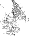
- FIG. 1 illustrates an agricultural field sprayer with which examples described herein can be used.
- FIG. 1 illustrates an agricultural environment 150 in which a tractor 160 is coupled to, and pulls, a towed sprayer 162.
- Towed sprayer 162 includes spray system 170, which has a tank 172 containing a liquid that is being applied to field 180.
- Tank 172 is coupled to boom 174, and the product is delivered to spray nozzles 176, which are spaced apart along boom 174. It is important, in environment 150, that product is evenly distributed across field 180. For example, if fertilizer is unevenly applied, it is wasted in areas of over-application, and areas of under-application can see reduced yields.
- FIGS. 2A-2C illustrate example spray patterns from spray nozzles within a spray system.
- FIG. 2A is a diagrammatic representation of an example spray system 200 having a number of spray nozzles 210 spaced apart along boom 202. Each spray nozzle 210 generates a dispersal 220 of sprayed or otherwise atomized product. As illustrated in FIG. 2A , spray nozzle 215 is at least partially plugged, creating an overlap area 212, where distributed product is overapplied, and an uncovered area 214, where no product is applied.
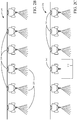
- FIGS. 2B and 2C illustrate a contrast between a properly functioning spray system 250 and a spray system 270 that has a plugged spray nozzle 240.
- area 242 will receive no dispersed product. This can result in lower yield for the portion of the field covered by area 242.
- a plugged spray nozzle also impacts the spray quality as the target application rate is not achieved for a portion of the field.
- FIGS. 3A and 3B illustrate systems for detecting spray nozzle plugging in accordance with an embodiment of the present invention.
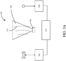
- FIG. 3A is a diagrammatic view of RF-based plugged nozzle detection in accordance with one example.
- Nozzle 310 when functioning properly, emits product in a predictable dispersal pattern 320.
- An RF transmission 315 sent from signal transmitter 312, passes through dispersal pattern 320, and is detected by RF signal detector 314.
- the RF signal 315 is detectably changed as it passes through dispersal pattern 320. This detectable change is generally a change in the attenuation of the signal.
- controller 317 coupled to transmitter 312 and receiver 314, can detect a change in the received signal by monitoring one or more characteristics of the RF signal (such as amplitude) using receiver 314. In this way, controller 317 detects changes indicative of plugging and provides a useful ability to diagnose, and/or correct, a plugged nozzle quickly.
- Controller 317 can be any suitable logic or circuit arrangements that are able to receive an output signal from receiver 314 and analyze the output to detect partial or full nozzle plugging.
- controller 317 is a microprocessor. Controller 317 may be separate from each of transmitter 312 and receiver 314 or it may be combined with either of transmitter 312 or receiver 314.
- the techniques described herein employ RF energy to detect spray nozzle plugging and thus do not employ optical techniques, which can be distorted or otherwise affected by dirt, dust, darkness or other variables.
- Rain fade describes the attenuation of the RF signal as it passes through and is at least partially absorbed by atmospheric snow, ice or rain. Rain fade is particularly evident at RF frequencies above 11 GHz and is typically a quantity that is compensated for in electromagnetic transmissions.
- One particularly useful range of RF signals for embodiments described herein is a frequency range from about 7 GHz to about 55 GHz.
- FIG. 3B illustrates a spray system 350 for a plurality of nozzles 360 mounted on boom 352.
- each nozzle 360 is paired with an RF signal transmitter (not shown) that emits a signal 362.
- each transmitter transmits a signal of the same amplitude but with a different frequency to that the RF receiver can differentiate the various signals.
- the RF transmitters can be positioned close to each of nozzles 360, such that each RF signal will pass through the dispersal pattern of its respective nozzle and be received by RF signal receiver 314.
- the signal transmitters can be placed next to each nozzle 360, as well as above or below each nozzle 360 as long as the RF signal passes through the dispersal pattern of the respective nozzle.
- the signal transmitters can be mounted directly to boom 352, or to each of nozzles 360, or in other appropriate locations.
- RF receiver 314 is configured to substantially simultaneously receive RF signals relative to each of nozzles 360. However, it is also contemplated that RF receiver 314 may be configured to alternatively receive and analyze incoming RF signals relative to each nozzle 360 sequentially. The system, thus is able to provide a substantially real-time indication of the current efficacy of each nozzle during operation.
- FIG. 4A illustrates a multi-nozzle spray system employing RF-based plugging detection in accordance with an example of the present description.
- System 400 includes a boom 402 coupled to a plurality of multi-nozzle bodies 410.
- multi-nozzle bodies 410 are used to deliver effective coverage over more area in less time. Using multiple nozzles allow an increase in productivity by better tolerating changes in spray speed.
- the group of nozzles can be used to deliver a single product at varying rates depending on how many individual nozzles are engaged. Additionally, the utilization of various nozzles can provide better placement precision of the product.
- multi-nozzle bodies 410 are those sold in relation to the trade designation ExactApplyTM Nozzle Control, available from John Deere Corporation, of Moline, Illinois.
- each multi-nozzle body 410 is configured to mount a plurality of spray nozzles, such as first nozzle 412 and a second nozzle 414.
- First nozzle 412 and second nozzle 414 are diametrically opposite one another on multi-nozzle body 410.
- a multi-nozzle body 410 can be coupled to more than two nozzles; for example, FIG. 4A shows five nozzles for each multi-nozzle body 410.
- Each multi-nozzle body 410 also includes, or is coupled to, an RF transmitter 430 that is configured to emit an RF signal.
- the RF signal is omnidirectional emanating outwardly from the center of multi-nozzle body 410.
- the RF signal will pass through the dispersal patterns of any individual nozzles that are engaged.
- the RF signal passing through the droplets of each dispersal pattern will be attenuated, or otherwise affected.
- An RF receiver positioned to detect the RF signal after passing through such a dispersal pattern is then used to detect whether a particular nozzle's pattern has changed.
- FIG. 4B illustrates an agricultural sprayer 550 with a pair of RF receivers 560, 570 to receive RF signals relative to multiple individual nozzles of a multi-nozzle body 410 in accordance with an embodiment of the present invention.
- first RF receiver 560 is mounted near solution tank 554, and second RF receiver 570 is located on the back side of a boom 552.
- Both first and second receivers 560, 570 receive the same signal from each multi-nozzle body RF transmitter 430.
- the signal received by first RF receiver 560 will be attenuated by the nozzle 412 (shown in FIG. 4A ) while the signal received by second RF receiver 570 will be attenuated by nozzle 414 (shown in FIG.
- First and second receivers 560, 570 are coupled to a suitable controller, such as a controller of the agricultural machine, which analyzes the received signals to provide a plugging indication relative to the various nozzles, such as nozzles 412, and 414. This analysis may be as simple as merely comparing the two signals, such that any difference between the two signals can be used to indicate which nozzle of the pair of nozzles is plugged, either partially or fully.
- a suitable controller such as a controller of the agricultural machine
- FIGS. 5A and 5B illustrate a multi-nozzle system employing RF-based plugging detection in accordance with another example of the present description.
- FIG. 5A is a bottom view of a multi-nozzle body having a plurality of individual RF transmitters, where each individual nozzle 610 of the multi-nozzle assembly has an associated RF transmitter 620.
- each individual nozzle 610 of the multi-nozzle assembly has an associated RF transmitter 620.
- only a subset set of nozzles 610 is active (for example, one pair of nozzles 610), only a subset of the associated transmitters 620 are also active.
- the RF signal transmitted by each RF transmitter 620 is attenuated by surrounding spray nozzles 610.
- any suitable technique for disambiguating the signals can be employed.
- one RF transmitter 620 may operate in a first frequency range, while another RF transmitter 620 may operate in a second frequency range that does not overlap the first frequency range.
- the different RF transmitters 620 may provide different modulation of their respective RF signals. Further still, the different RF transmitters 620 may be operated in sequence such that only a single RF transmitter 620 is operating at any given time.
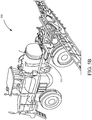
- FIG. 5B illustrates an agricultural sprayer 500 with RF receiver 510 mounted proximate a solution tank and configured to detect signals from the various RF transmitters 620 (shown in FIG. 5A ).
- a controller coupled to RF receiver 510 is configured to compare data from each nozzle with default data stored in the controller, or in another suitable location, that indicates normal nozzle operation. Based on the comparison to the default data, the controller can determine if a particular nozzle or pair of nozzles has partial or full plugging.
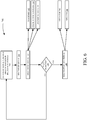
- FIG. 6 illustrates a flow diagram of a method of detecting a plugged spray nozzle in accordance with an example of the present description.
- Method 700 can be used to detect a partial or fully plugged status of a nozzle on an agricultural sprayer. Method 700 can also be used with at least some of the single and multi-nozzle systems described herein, or others.
- Method 700 begins at block 705 where an RF signal is generated by a transmitter and passes through a dispersal area of at least one nozzle.
- the RF signal is received using an RF receiver, such as receiver 510.
- the received RF signal is analyzed. Analyzing the received RF signal, can include comparing the signal with a standard signal obtained and stored during known-good spraying conditions, as indicated in block 712.
- the standard can include a manufacturer-provided range of acceptable RF signals, or an indication of RF signals that indicate partial or complete plugging.
- Analyzing the received RF signal can additionally or alternatively include comparing the received signal with one or more received signals relative to other nozzles, as indicated in block 714.
- using an average of a set of received RF signals can indicate that one or more nozzles in a set of nozzles is plugged, for example because the RF signal received from the plugged nozzle is different from the average in a statistically significant way.
- Historical data for a nozzle can also be used to detect full or partial plugging, as indicated in block 716. For example, a received RF signal will change as plugging is experienced, and the RF signal travels through a thinner, or non-existent spray.
- method 700 proceeds to block 740 where an indication of plugging is provided. However, in the event that no plugging is detected for a particular nozzle, method 700 returns to block 705, and thus repeats.
- an indication of a plugged nozzle status is generated and sent.
- an indication can be sent directly to an operator, as indicated in block 742, for example as an audible or visual alert.
- a notification can be provided to an operator's device, such as a mobile phone.
- the indication can also be sent directly to the agricultural sprayer, as indicated in block 744, for remedial action, such as automatically switching to a different pair of active nozzles in a multi-nozzle assembly, increasing or pulsing the fluid pressure in an attempt to clear the plug, etc.
- FIG. 7 illustrates an environment in which examples of the present description can be used.
- Sprayer system 810 is located within environment 800, and may be mounted to an agricultural vehicle, or towed by an agricultural vehicle, as illustrated in FIG. 1 .
- Sprayer system 810 has one or more nozzles 802, either mounted directly to a boom, or to a nozzle body. Each nozzle 802 is associated with an RF transmitter 804.
- the signals generated by RF transmitter(s) 804 are configured to pass through respective dispersal areas of respective nozzles 802 and be attenuated or otherwise distorted by droplets of liquid in the dispersal area. The distorted RF signal is then detected by an RF receiver 806.
- Sprayer system 810 may include a single RF receiver 806 (such as described above with respect to FIGS. 5A and 5B ) configured to receive signals alternatively from different RF transmitters 804 or sprayer system 810 may employ two or more RF receivers 806 (such as described above with respect to FIGS. 4A and 4B
- RF-based plug detection system 820 which may be located locally, for example as part of a computing unit within an agricultural vehicle, or remotely from an agricultural vehicle, for example within a separate computing system.
- RF-based plug detection system 820 includes storage component 830, which stores nozzle data 832, obtained from a plurality of nozzles 802, for example.
- Nozzle data 832 can be analyzed to detect a partial or completely plugged status within a nozzle 802.
- historical data analyzer 840 can compare contemporaneously received nozzle data for a nozzle 802 to historical nozzle data 832 and detect a statistically significant difference.
- comparative data analyzer 860 can compare nozzle data 832 from a single nozzle, to a known-good standard.
- the known-good standard can include an average of contemporaneously received data 832 from all nozzles 802.
- the known-good standard can include a standard provided from a manufacturer.
- plug status detector 850 Based on a comparison, for example from historical data analyzer 840 or comparative data analyzer 860, plug status detector 850 detects that a nozzle 802 is experiencing partial or complete plugging, and generates a plugging indication. The plugging indication is then transmitted by communication component 870 to an operator 880, for example through a display on the agricultural vehicle, or through a display on a device associated with operator 880.
- examples described thus far generally use electromagnetic radiation in the form of radio-frequency transmissions to diagnose or otherwise detect conditions related to spray nozzle plugging, either partial or full, other forms of electromagnetic radiation can also be used in accordance with examples described herein.
- electromagnetic radiation in the form of thermal imaging can be used in addition to or instead of the radio-frequency transmission techniques.
- examples may employ a thermal imaging camera for detection of nozzle blockage and/or spray characterization. When the sprayed liquid chemical comes in contact with plants, thermal changes occur to the plants. These thermal changes are captured by a thermal imaging camera that is installed either on the spraying device, or other suitable device, and analyzed to determine whether any nozzle of the agricultural is partially or fully blocked. This analysis generally employs using a heat signature to determine the spraying pattern.
- substantially all sprayed crops will have the same thermal characteristics. If, however, one or more of the spray nozzles begin to function poorly or not at all, then the crop immediately below and behind the malfunctioning nozzle(s) will not undergo the thermal changes induced by receiving a liquid spray and such condition is detectable using thermal imaging.
- the thermal change is due to evaporative cooling of a liquid chemical being applied to a dry crop or surface.
- the temperature of the sprayed crop or surface is reduced relative to the surrounding environment.
- a thermodynamic or chemical effect that causes the sprayed crop or surface to change temperature relative to the ambient background.
- other conditions could also result in thermal changes of the sprayed crops or surface.
- a chemical reaction between the applied chemical and the crop could be exothermic or endothermic.
- the applied chemical could be heated or cooled such that it is applied at a temperature that is different than the ambient environment.
- FIG. 8 is a diagrammatic view of an agricultural sprayer employing thermal imaging-based sprayer detection in accordance with an example of the present description.
- Sprayer 900 includes a tank 902 containing a liquid chemical to be applied via one or more nozzles 904 to a crop. Additionally, agricultural sprayer 900 also includes a thermal imaging camera 906 disposed on roof 908 and arranged to have a field of view 910 that substantially encompasses the sprayed width behind agricultural sprayer 900.
- Thermal imaging camera 906 can be any suitable device that provides imaging in the form of either discrete images, or video, based on infrared heat detection. Typically, such cameras view the electromagnetic spectrum of approximately 9,000-14,000 nanometers and produce images of radiation in that wavelength spectrum.
- Thermal imaging camera 906 may be coupled to an analysis device, such as a controller of agricultural sprayer 900, or a plug detection system such as plug detection system 820 (shown in FIG. 7 ) in order to analyze one or more thermal images to characterize sprayer or nozzle performance.
- the actual connection between thermal imaging camera 906 and the analysis device can be via a wired connection, a wireless connection, such as WIFI, or any other suitable technique. Additionally, or alternately, the thermal image may simply be provided to the operator of agricultural sprayer 900 to provide an indication of sprayer efficacy.
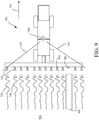
- FIG. 9 is a top plan view of agricultural sprayer 900 applying liquid spray 920 via sprayers 904 to a field or agricultural surface 922.
- Agricultural sprayer 900 is moving in the direction indicated by arrow 924 and all sprayer nozzles 904, with the exception of nozzle 926, are spraying essentially nominally.
- a detectable thermal change begins immediately and then stabilizes as the liquid dries onto the agricultural surface.
- the diagrammatic representation of the thermal change is indicated at reference numerals 928. As can be seen, in the portion of agricultural surface 922 that is immediately behind malfunctioning sprayer nozzle 926, no thermal change is occurring.
- Thermal imaging system 906 sees this region 930 within field of view 910 and can provide an automatic indication of the malfunction of nozzle 926 to the operator of agricultural sprayer 900. Further, a video output of the image provided by thermal imaging system 906 may also provide an intuitive output to the operator who may see that the applied thermal field is not even and that something is wrong or at least requiring additional attention or diagnosis.
- the identification of a malfunctioning nozzle can be used both in terms of identifying such occurrence quickly such that crop effects can be mitigated, but also to ensure that the situation is repaired or otherwise ameliorated as quickly as possible such that effective spraying can resume quickly.
- FIGS. 8 and 9 provide a thermal imaging system mounted to an agricultural sprayer and configured to observe or otherwise detect the application of a sprayed liquid chemical to an agricultural crop or field, examples can be employed where the thermal imaging system is not directly attached to the agricultural sprayer.
- FIG. 10 is a diagrammatic view of an agricultural sprayer applying a liquid chemical to an agricultural surface using a number of spray nozzles.
- one or more unmanned aerial vehicles are programmed to follow the agricultural sprayer and include a thermal imaging system that is directed to the agricultural field immediately behind the sprayers relative to the direction of travel 924.
- the thermal imaging system(s) on the drone(s) actually detects the thermal images.
- the drone image data can be transmitted to a suitable analytical device, such as plug detection system 820, or provided to a display for the operator of agricultural sprayer 900.
- thermal imaging of the application of a liquid chemical to an agricultural surface or crop may also provide the identification of problems even as they are beginning and may aid in the preventative maintenance of spray nozzles.
- FIG. 11 is a flow diagram of a method of assessing spray nozzle operation of an agricultural sprayer in accordance with an example of the present description.
- Method 1000 begins at block 1002 marked spray start.
- the agricultural sprayer begins applying a liquid chemical to a crop or agricultural field.
- a thermal image of the crop or field with the liquid chemical just applied is acquired.
- the acquired or captured thermal image is processed by an image processor to identify a heat signature and determine the spray pattern.
- individual nozzle spray is characterized by the image processor. Such characterization can include providing an indication (such as a percentage) regarding a degree to which the nozzle is plugged.
- the image processing can be performed by a user, any suitable algorithm or artificial intelligence routine, or other suitable techniques.
- An output can be provided to the user that characterizes the blockage for each nozzle as a percentage of total blockage, and may provide an indication of whether a nozzle should be cleaned versus replaced.
- FIG. 12 is a pictorial illustration of another example in which aspects of the present description can be used.
- FIG. 12 shows a spreader 1020 which spreads dry matter (which maybe particulate or granular matter, such as fertilizer) on an agricultural field.
- FIG. 12 shows that spreader 1020 has an operator compartment 1022 and a bin 1024.
- Bin 1024 holds the dry material which may be top loaded, or otherwise loaded, into bin 1024.
- a conveyor (not shown) is located beneath bin 1024 and carries the dry material, as it drops from bin 1024 onto the conveyor, toward the rear of spreader 1020.
- An air boom 1026 includes a plurality of delivery pipes (or conduits), some of which are labeled 1028-1042.
- the delivery pipes extend from a generally central region of boom 1026 and terminate at different distances from the central region of boom 1026 along the longitudinal axis of boom 1026. Therefore, some of the pipes terminate closely adjacent the center portion of boom 1026, such as pipe 1044. Other pipes terminate out further toward the distal end of boom 1026, such as pipe 1028. While FIG. 12 shows an arrangement for boom 1026 on the driver's side of spreader 1020, boom 1026 may have a similar arrangement on the opposite side of spreader 1020 as well.
- a fan 1046 generates air pressure in the delivery pipes of boom 1026.
- the air pressure moves air from the central region of boom 1026 toward the distal end and out the exit end of each of the pipes that form 1026.
- the dry material is moved from bin 1024 by the conveyor, into each of the delivery pipes, through a manifold that is connected to the inlet openings of each pipe.
- the dry material is then carried from where it enters the pipes to the outlet end of each of the pipes by the air introduced into those pipes by fan 1046.
- Each of the pipes has a corresponding deflector (mounted proximate the outlet ends of the pipes) which deflects the material (after it exits the outlet end of the corresponding delivery pipe) downwardly onto the agricultural field over which spreader 1020 is traveling.
- delivery pipe 1028 has a corresponding deflector 1029.
- Delivery pipe 1030 has a corresponding deflector 1032, etc. As the particulate material exits through the outlet end of the corresponding delivery pipe, its corresponding deflector deflects the material downward, through a dispersal area, onto the field.
- FIG. 13 is a more detailed illustration of a deflector.
- FIG. 13 shows one of the delivery pipes (e.g., delivery pipe 1032) that has an outlet end 1050. Material travels out of the outlet end 1050 generally in the direction indicated by arrow 1052, as it is carried by the air being forced through pipe 1032 by fan 1046.
- Deflector 1031 deflects the air flow (and hence the material carried by the air flow) so that it is directed rearwardly, as indicated by arrow 1054.
- the rearwardly directed material then interacts with a downward extending portion 1056 of deflector 1031 so that the material is then deflected downwardly, as indicated by arrow 1058, onto the field over which spreader 1020 is traveling.
- This same arrangement is illustratively provided proximate the exit ends of each of the delivery pipes on both sides of boom 1026.
- the dry material is particulate or granular, or power-like.
- the material flows easily under the influence of the air traveling through the delivery pipes, from an entry manifold (at the inlet end of each pipe) to the exit end of the delivery pipes.
- the corresponding deflectors then deflect the material downwardly onto the field.
- Each deflector thus causes the material to be deflected downwardly, passing through a dispersal area, which is similar to the various dispersal areas 220 shown in FIG. 2A , and onto the agricultural field.
- the dry material can clump or acquire other characteristics that make it difficult to distribute through spreader 1020 (such as through the conveyor, through the manifold into the delivery pipes, and out the exit end of the delivery pipes, onto the field, by interacting with the deflector). For instance, if moisture is introduced into the bin 1024, or into the system at another place, this can cause the dry material to clump or otherwise acquire a characteristic (such as stickiness or adhesiveness) which makes it difficult to spread using an air spreader. Under such conditions, the material can become plugged anywhere in spreader 1020.
- Radio frequency signals are attenuated, or take on another measurable or detectable characteristic, as they pass through a cloud of particulate or dry material, such as the dispersal area of dry material created at the outlet end of the delivery pipes and deflectors of spreader 1020.
- boom 1026 has a plurality of radio frequency components mounted closely proximate each of the deflectors on boom 1026. Some of the radio frequency components are labeled 1059-1082. As described above with respect to the sprayer example, these components can emit a radio frequency signal.
- a radio frequency receiver 1084 which can be mounted to a central portion of spreader 1020, can detect or read those signals after they pass through the corresponding dispersal areas.
- the attenuation (or other characteristic) of each of the RF signals, emitted by each of the RF transmitters can be analyzed to determine whether the attenuation is the same as that which is expected for an RF signal passing through a dispersal area of the dry material being applied.
- a plug condition e.g., partial or total blockage of the individual delivery pipes or deflectors
- each of the RF components 1059-1082 can illustratively be RF receivers. They are positioned on the opposite side of the dispersal area corresponding to the deflectors that they are mounted next to, and can thus detect signal attenuation that results from the RF signals transmitted by the centrally located RF transmitter, through the corresponding dispersal area.
- the RF receivers will sense a more heavily attenuated signal, if the transmitted RF signal passes through a dispersal area where the dry material is actually being dispersed. However, if it passes through a dispersal area for a plugged or partially plugged delivery pipe or deflector, then the signal will not be as heavily attenuated.
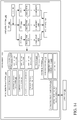
- FIG. 14 is a block diagram of an environment 1100 which shows a spreader system 1102 which includes some of the items on spreader 1020. It also includes a plug detection system 1104 which can be disposed on spreader 1020 or elsewhere.
- Spreader system 1102 shows some items described above. However, it illustratively includes pipe N, its corresponding deflector N and RF component N. This notation illustrates that an RF component can be positioned on boom 1026 so that it transmits an RF signal through the dispersal area corresponding to each deflector on boom 1026, and each delivery pipe.
- plug detection system 1104 is similar to plug detection system 820 shown in FIG. 7 , and similar items are similarly numbered.
- data store 830 including nozzle data
- it illustratively represents what would be expected attenuation if spreader system 1102 is operating properly.
- the deflector data 1106-1112 can be historical data which is captured during proper operation of spreader system 1102. In another example, it can be comparative data so that, for instance, when the RF attenuation (or other characteristic) is identified for a particular delivery pipe and deflector, it can be compared to the same information for the corresponding delivery pipe and deflector on the opposite side of boom 1026. In such an example, the two delivery pipes will have the same length, and therefore they will have similar resistance to air flow and other characteristics. Thus, the signal attenuation resulting from the RF signal passing through the corresponding dispersal areas can be expected to be similar.
- data store 830 can include both comparative data, and historical data so that a measured RF signal characteristic can be compared to both references.
- the data in data store 830 represents modeled data indicating the expected RF signal characteristics, even though it does not represent actual comparative data or historical data. All of these and other types of data are contemplated herein.
- Data store 830 can include a wide variety of other information 1114, as well.
- FIG. 14 also shows that plug detection system 1104 can have a control signal generator 1116 which can generate control signals to control various items in controllable subsystems 1118.
- the controllable subsystems 1118 can include such things as fan controller 1120, communication controller 1122 and a wide variety of other items 1124.
- Fan controller 1120 can illustratively control fan 1046. For instance, when plug status detector 850 detects a plug, fan controller 1120 can increase the fan speed to increase the pressure in boom 1026 in an attempt to eliminate the plug. Similarly, fan controller 1120 can vary the fan speed to pulse the pressure within boom 1026, again in an attempt to eliminate the plug.
- Communication controller 1122 can control communication component 870 to generate communication indicative of the fact that a plug exists and send that to various systems. For instance, it can control operator interface mechanisms 1126 to generate an alert.
- Operator interface mechanisms 1126 can include such things as a display mechanism, an audio mechanism, or a haptic feedback mechanism, all of which can be used to generate an alert for operator 880.
- the operator interface mechanisms 1126 can include handheld or other mobile devices that are carried by operator 880 in operator compartment 1022.
- communication component 870 can be controlled to communicate with a remote computing system, such as a farm manager's computing system, the computing system of maintenance personnel, etc.
- FIG. 15 is a flow diagram illustrating one example of the operation of environment 1110 in detecting plug conditions in the spreader system 1102 of spreader 1020. It is first assumed that spreader 1020 has begun a spreading operation and is spreading the material from bin 1024. This is indicated by block 1130 in the flow diagram of FIG. 15 . In the example being discussed, the deflectors are creating dispersal areas where the dry material is being dispersed onto the field. This is indicated by block 1132. Spreader 1020 can be spreading material in other ways as well, and this is indicated by block 1134.
- an RF transmitter transmits an RF signal through the areas of dispersal relative to each of the deflectors on spreader 1020. This is indicated by block 1136.
- the RF components located on boom 1026 e.g., RF components 1059-1082
- each of the RF components on boom 1026 can be an RF receiver where component 1084 is an RF transmitter.
- the RF components on the boom 1026 are transmitters and the component 1084 is a receiver.
- RF receiver 1084 then receives the RF signals from the various transmitters. This is indicated by block 1138. In one example, it can distinguish between the RF signals transmitted by the different transmitters based upon the transmission frequency. In another example, they can be temporally distinguished in that each of the RF transmitters may transmit at a different time. In another example, they may be distinguished based on the phase with which they are transmitting the RF signal. In yet another example, each of the RF transmitters may be independently addressable by the receiver so that they can be actuated to transmit, under the control of the RF receiver 1084. All of these and other scenarios are contemplated herein.
- Plug detection system 1104 then analyzes the RF signals to determine whether a plug condition is detected. This is indicated by block 1140.
- historical data analyzer 840 can analyze the received RF signal for a particular transmitter against historical data to see whether the received RF signal has expected characteristics (such as an expected amplitude, attenuation, etc.).
- comparative data analyzer 860 can compare the RF signal received by the transmitter under analysis against the RF signals received by other RF transmitters on boom 1026 to determine whether it is similar, or varies in an expected way, from those other signals.
- plug status detector 850 determines whether there is a plug conditions (e.g., full or partial plug) in the spreading system of spreader 1020. This is indicated by block 1142. If so, it provides an indication of this to control signal generator 1116 which generates an action signal based upon the detected plug. This is indicated by block 1144.
- a plug conditions e.g., full or partial plug
- the action signal controls the fan controller 1120 to increase air pressure or pulse the air pressure in boom 1126 in response to detecting a plug. This can be done in an attempt to dislodge the plug. Increasing the air pressure is indicated by block 1146 and pulsing the air pressure is indicated by block 1148.
- communication controller 1122 can control communication component 870 to generate an alert or another output message for operator 880. This is indicated by block 1150.
- the alert can be a visible, audio or haptic alert. It can be a display that shows the dispersal areas that are operating, and those that are not operating properly, or a wide variety of other things.
- Controllable subsystem 1118 can be controlled in other ways, in response to the control signals generated by control signal generator 1116 as well. This is indicated by block 1152 in the flow diagram of FIG. 15 . This type of operation continues until the spreading operation is complete. This is indicated by block 1154. Also, the figures show a number of blocks with functionality ascribed to each block. It will be noted that fewer blocks can be used so the functionality is performed by fewer components. Also, more blocks can be used with the functionality distributed among more components.
- processors and servers include computer processors with associated memory and timing circuitry, not separately shown. They are functional parts of the systems or devices to which they belong and are activated by, and facilitate the functionality of the other components or items in those systems.
- systems, components and/or logic can be comprised of hardware items (such as processors and associated memory, or other processing components, some of which are described below) that perform the functions associated with those systems, components and/or logic.
- the systems, components and/or logic can be comprised of software that is loaded into a memory and is subsequently executed by a processor or server, or other computing component, as described below.
- the systems, components and/or logic can also be comprised of different combinations of hardware, software, firmware, etc., some examples of which are described below.
- the user actuatable input mechanisms can be text boxes, check boxes, icons, links, drop-down menus, search boxes, etc. They can also be actuated in a wide variety of different ways. For instance, they can be actuated using a point and click device (such as a track ball or mouse). They can be actuated using hardware buttons, switches, a joystick or keyboard, thumb switches or thumb pads, etc. They can also be actuated using a virtual keyboard or other virtual actuators. In addition, where the screen on which they are displayed is a touch sensitive screen, they can be actuated using touch gestures. Also, where the device that displays them has speech recognition components, they can be actuated using speech commands.
- a number of data stores have also been discussed. It will be noted they can each be broken into multiple data stores. All can be local to the systems accessing them, all can be remote, or some can be local while others are remote. All of these configurations are contemplated herein.
- the figures show a number of blocks with functionality ascribed to each block. It will be noted that fewer blocks can be used so the functionality is performed by fewer components. Also, more blocks can be used with the functionality distributed among more components.
Landscapes
- Engineering & Computer Science (AREA)
- Radar, Positioning & Navigation (AREA)
- Remote Sensing (AREA)
- Life Sciences & Earth Sciences (AREA)
- Environmental Sciences (AREA)
- General Physics & Mathematics (AREA)
- Physics & Mathematics (AREA)
- Computer Networks & Wireless Communication (AREA)
- Insects & Arthropods (AREA)
- Pest Control & Pesticides (AREA)
- Wood Science & Technology (AREA)
- Zoology (AREA)
- Water Supply & Treatment (AREA)
- Soil Sciences (AREA)
- Catching Or Destruction (AREA)
Abstract
Description
- This description relates to a spraying and/or a spreading apparatus for applying material to an agricultural field. More specifically, the description relates to detecting full or partial plugging of a spray nozzle of an agricultural sprayer and/or a pipe or deflector of an agricultural spreader.
- Agricultural spraying and spreading systems are known. Such systems typically include a delivery line or conduit mounted on a foldable, hinged, or retractable and extendible boom. In a sprayer, the delivery line is coupled to one or more spray nozzles mounted along the boom. Each spray nozzle is configured to receive the fluid and direct atomized fluid to a crop or field during application.
- Spraying operations are generally intended to distribute a product (e.g. fertilizer, herbicides, pesticides, etc.) evenly over an agricultural surface, such as a field or crop. Properly functioning spray nozzles ensure that dispersal of the product occurs evenly and is important to ensure crop yields.
- In an agricultural spreader, the material to be applied (e.g., fertilizer, pesticide, herbicide, etc.) is held in a bin, and is a dry material, which may be particulate (e.g., granular). A conveyor carries the dry material from the bin to an outlet which feeds the material into a series of conduits (e.g., tubes or pipes) which extend outwardly along the boom. A fan generates pressurized air in the conduits to move the dry product outwardly, through the pipes, to an exit end of the pipes. A deflector is disposed proximate the exit end of each pipe to deflect the dry material downwardly onto the field where it is being applied.
- An agricultural spreader includes at least one delivery conduit that carries material to be spread from a bin to an exit end of the delivery conduit under the influence of air blown through the delivery conduit by a fan. A deflector is mounted proximate the exit end of the delivery conduit and deflects the material onto an agricultural field in a dispersal area. A radio frequency (RF) transmitter is disposed to generate an RF signal that passes through the dispersal area. The RF signal is detectably changed when interacting with the material passing through the dispersal area. An RF receiver is disposed to receive the RF signal after the RF signal passes through the dispersal area and provides an output indicative of the RF signal. A controller is coupled to the RF receiver and detects plugging of the delivery conduit based on the output of the RF receiver.
- This Summary is provided to introduce a selection of concepts in a simplified form that are further described below in the Detailed Description. This Summary is not intended to identify key features or essential features of the claimed subject matter, nor is it intended to be used as an aid in determining the scope of the claimed subject matter. The claimed subject matter is not limited to implementations that solve any or all disadvantages noted in the background.
-
-
FIG. 1 illustrates an agricultural field sprayer with which examples described herein are particularly useful. -
FIGS. 2A-2C illustrate example spray patterns from spray nozzles within a spray system. -
FIGS. 3A and3B illustrate systems for detecting spray nozzle plugging in accordance with an example of the present description. -
FIGS. 4A and4B illustrate a multi-nozzle system employing RF-based plugging detection in accordance with an example of the present description. -
FIGS. 5A and5B illustrate a multi-nozzle system employing RF-based plugging detection in accordance with another example of the present description. -
FIG. 6 is a flow diagram of a method of detecting a plugged nozzle using RF transmissions in accordance with an example of the present description. -
FIG.7 illustrates an environment in which examples described herein are particularly useful. -
FIG. 8 is a diagrammatic view of an agricultural sprayer employing thermal imaging-based sprayer detection in accordance with an example of the present description. -
FIG. 9 is a top plan view of agricultural sprayer with a thermal imager applying liquid spray via sprayers to a field or agricultural surface in accordance with an example of the present description. -
FIG. 10 is a diagrammatic view of an agricultural sprayer applying a liquid chemical to an agricultural surface using a number of spray nozzles and a thermal imager in accordance with an example of the present description. -
FIG. 11 is a flow diagram of a method of assessing spray nozzle operation of an agricultural sprayer in accordance with an example of the present description. -
FIG. 12 is a pictorial illustration of an agricultural spreader that spreads dry material on an agricultural field. -
FIG. 13 is an enlarged view of an exit end of a delivery pipe and a deflector on the agricultural spreader shown inFIG. 12 . -
FIG. 14 is a block diagram of one example of an agricultural spreader. -
FIG. 15 is a flow diagram showing one example of the operation of an agricultural spreader. - Examples described herein generally employ electromagnetic radiation to detect a change in output from one or more spray nozzles or delivery conduits (e.g., pipes). In one example, the electromagnetic radiation is in the form of radio-frequency transmissions. As the radio-frequency energy of the transmission passes through the droplets generated by the spray nozzle, or the material being spread from a delivery pipe and deflector, the RF signal is changed in a detectable way. An RF receiver, configured to detect the RF signal that has passed through the spray, or dry material, provides an output that is monitored to provide diagnostic indications. As used herein, radio-frequency (RF) is defined to mean electromagnetic energy having a frequency in the range from about 3kHz to about 300 GHz.
- In another example, the electromagnetic radiation is in the form of thermal imaging that is used to view a thermal change on the agricultural surface or crop upon receiving an applied liquid spray.
-
FIG. 1 illustrates an agricultural field sprayer with which examples described herein can be used.FIG. 1 illustrates anagricultural environment 150 in which atractor 160 is coupled to, and pulls, atowed sprayer 162.Towed sprayer 162 includesspray system 170, which has atank 172 containing a liquid that is being applied tofield 180.Tank 172 is coupled toboom 174, and the product is delivered tospray nozzles 176, which are spaced apart alongboom 174. It is important, inenvironment 150, that product is evenly distributed acrossfield 180. For example, if fertilizer is unevenly applied, it is wasted in areas of over-application, and areas of under-application can see reduced yields. -
FIGS. 2A-2C illustrate example spray patterns from spray nozzles within a spray system.FIG. 2A is a diagrammatic representation of anexample spray system 200 having a number ofspray nozzles 210 spaced apart alongboom 202. Eachspray nozzle 210 generates adispersal 220 of sprayed or otherwise atomized product. As illustrated inFIG. 2A ,spray nozzle 215 is at least partially plugged, creating anoverlap area 212, where distributed product is overapplied, and anuncovered area 214, where no product is applied. -
FIGS. 2B and 2C illustrate a contrast between a properly functioningspray system 250 and aspray system 270 that has a pluggedspray nozzle 240. As illustrated inFIG. 2C , becausespray nozzle 240 is fully plugged,area 242 will receive no dispersed product. This can result in lower yield for the portion of the field covered byarea 242. Additionally, a plugged spray nozzle also impacts the spray quality as the target application rate is not achieved for a portion of the field. -
FIGS. 3A and3B illustrate systems for detecting spray nozzle plugging in accordance with an embodiment of the present invention.FIG. 3A is a diagrammatic view of RF-based plugged nozzle detection in accordance with one example.Nozzle 310, when functioning properly, emits product in apredictable dispersal pattern 320. AnRF transmission 315, sent fromsignal transmitter 312, passes throughdispersal pattern 320, and is detected byRF signal detector 314. TheRF signal 315 is detectably changed as it passes throughdispersal pattern 320. This detectable change is generally a change in the attenuation of the signal. Thus,controller 317 coupled totransmitter 312 andreceiver 314, can detect a change in the received signal by monitoring one or more characteristics of the RF signal (such as amplitude) usingreceiver 314. In this way,controller 317 detects changes indicative of plugging and provides a useful ability to diagnose, and/or correct, a plugged nozzle quickly.Controller 317 can be any suitable logic or circuit arrangements that are able to receive an output signal fromreceiver 314 and analyze the output to detect partial or full nozzle plugging. In one example,controller 317 is a microprocessor.Controller 317 may be separate from each oftransmitter 312 andreceiver 314 or it may be combined with either oftransmitter 312 orreceiver 314. Advantageously, the techniques described herein employ RF energy to detect spray nozzle plugging and thus do not employ optical techniques, which can be distorted or otherwise affected by dirt, dust, darkness or other variables. - One example of electromagnetic energy being affected by passing through droplets of liquid is known as rain fade. Rain fade describes the attenuation of the RF signal as it passes through and is at least partially absorbed by atmospheric snow, ice or rain. Rain fade is particularly evident at RF frequencies above 11 GHz and is typically a quantity that is compensated for in electromagnetic transmissions. One particularly useful range of RF signals for embodiments described herein is a frequency range from about 7 GHz to about 55 GHz.
-
FIG. 3B illustrates aspray system 350 for a plurality ofnozzles 360 mounted onboom 352. In the illustrated example, eachnozzle 360 is paired with an RF signal transmitter (not shown) that emits asignal 362. In one example, each transmitter transmits a signal of the same amplitude but with a different frequency to that the RF receiver can differentiate the various signals. The RF transmitters can be positioned close to each ofnozzles 360, such that each RF signal will pass through the dispersal pattern of its respective nozzle and be received byRF signal receiver 314. For example, the signal transmitters can be placed next to eachnozzle 360, as well as above or below eachnozzle 360 as long as the RF signal passes through the dispersal pattern of the respective nozzle. Thus, the signal transmitters can be mounted directly toboom 352, or to each ofnozzles 360, or in other appropriate locations. - In one example,
RF receiver 314 is configured to substantially simultaneously receive RF signals relative to each ofnozzles 360. However, it is also contemplated thatRF receiver 314 may be configured to alternatively receive and analyze incoming RF signals relative to eachnozzle 360 sequentially. The system, thus is able to provide a substantially real-time indication of the current efficacy of each nozzle during operation. -
FIG. 4A illustrates a multi-nozzle spray system employing RF-based plugging detection in accordance with an example of the present description.System 400 includes aboom 402 coupled to a plurality ofmulti-nozzle bodies 410. In one example,multi-nozzle bodies 410 are used to deliver effective coverage over more area in less time. Using multiple nozzles allow an increase in productivity by better tolerating changes in spray speed. The group of nozzles can be used to deliver a single product at varying rates depending on how many individual nozzles are engaged. Additionally, the utilization of various nozzles can provide better placement precision of the product. In one example,multi-nozzle bodies 410 are those sold in relation to the trade designation ExactApplyTM Nozzle Control, available from John Deere Corporation, of Moline, Illinois. - As shown, each
multi-nozzle body 410 is configured to mount a plurality of spray nozzles, such asfirst nozzle 412 and asecond nozzle 414.First nozzle 412 andsecond nozzle 414 are diametrically opposite one another onmulti-nozzle body 410. As illustrated inFIG. 4A , amulti-nozzle body 410 can be coupled to more than two nozzles; for example,FIG. 4A shows five nozzles for eachmulti-nozzle body 410. Eachmulti-nozzle body 410 also includes, or is coupled to, anRF transmitter 430 that is configured to emit an RF signal. In one example, the RF signal is omnidirectional emanating outwardly from the center ofmulti-nozzle body 410. As can be appreciated, the RF signal will pass through the dispersal patterns of any individual nozzles that are engaged. The RF signal passing through the droplets of each dispersal pattern will be attenuated, or otherwise affected. An RF receiver positioned to detect the RF signal after passing through such a dispersal pattern is then used to detect whether a particular nozzle's pattern has changed. -
FIG. 4B illustrates anagricultural sprayer 550 with a pair ofRF receivers multi-nozzle body 410 in accordance with an embodiment of the present invention. As illustrated inFIG. 4B ,first RF receiver 560 is mounted nearsolution tank 554, andsecond RF receiver 570 is located on the back side of aboom 552. Both first andsecond receivers body RF transmitter 430. However, the signal received byfirst RF receiver 560 will be attenuated by the nozzle 412 (shown inFIG. 4A ) while the signal received bysecond RF receiver 570 will be attenuated by nozzle 414 (shown inFIG. 4A ). First andsecond receivers nozzles -
FIGS. 5A and5B illustrate a multi-nozzle system employing RF-based plugging detection in accordance with another example of the present description.FIG. 5A is a bottom view of a multi-nozzle body having a plurality of individual RF transmitters, where eachindividual nozzle 610 of the multi-nozzle assembly has an associatedRF transmitter 620. When only a subset set ofnozzles 610 is active (for example, one pair of nozzles 610), only a subset of the associatedtransmitters 620 are also active. The RF signal transmitted by eachRF transmitter 620 is attenuated by surroundingspray nozzles 610. - In examples where
multiple RF transmitters 620 are used, any suitable technique for disambiguating the signals can be employed. For example, oneRF transmitter 620 may operate in a first frequency range, while anotherRF transmitter 620 may operate in a second frequency range that does not overlap the first frequency range. Additionally, or alternatively, thedifferent RF transmitters 620 may provide different modulation of their respective RF signals. Further still, thedifferent RF transmitters 620 may be operated in sequence such that only asingle RF transmitter 620 is operating at any given time. -
FIG. 5B illustrates anagricultural sprayer 500 withRF receiver 510 mounted proximate a solution tank and configured to detect signals from the various RF transmitters 620 (shown inFIG. 5A ). In one example, a controller coupled toRF receiver 510 is configured to compare data from each nozzle with default data stored in the controller, or in another suitable location, that indicates normal nozzle operation. Based on the comparison to the default data, the controller can determine if a particular nozzle or pair of nozzles has partial or full plugging. -
FIG. 6 illustrates a flow diagram of a method of detecting a plugged spray nozzle in accordance with an example of the present description.Method 700 can be used to detect a partial or fully plugged status of a nozzle on an agricultural sprayer.Method 700 can also be used with at least some of the single and multi-nozzle systems described herein, or others. -
Method 700 begins at block 705 where an RF signal is generated by a transmitter and passes through a dispersal area of at least one nozzle. - At
block 710, the RF signal is received using an RF receiver, such asreceiver 510. Next, atblock 720, the received RF signal is analyzed. Analyzing the received RF signal, can include comparing the signal with a standard signal obtained and stored during known-good spraying conditions, as indicated inblock 712. The standard can include a manufacturer-provided range of acceptable RF signals, or an indication of RF signals that indicate partial or complete plugging. Analyzing the received RF signal can additionally or alternatively include comparing the received signal with one or more received signals relative to other nozzles, as indicated inblock 714. For example, using an average of a set of received RF signals can indicate that one or more nozzles in a set of nozzles is plugged, for example because the RF signal received from the plugged nozzle is different from the average in a statistically significant way. Historical data for a nozzle can also be used to detect full or partial plugging, as indicated inblock 716. For example, a received RF signal will change as plugging is experienced, and the RF signal travels through a thinner, or non-existent spray. Atblock 730, if a partial or fully plugged sensor is detected,method 700 proceeds to block 740 where an indication of plugging is provided. However, in the event that no plugging is detected for a particular nozzle,method 700 returns to block 705, and thus repeats. - At
block 740, an indication of a plugged nozzle status is generated and sent. For example, an indication can be sent directly to an operator, as indicated inblock 742, for example as an audible or visual alert. Additionally, or alternatively, a notification can be provided to an operator's device, such as a mobile phone. The indication can also be sent directly to the agricultural sprayer, as indicated inblock 744, for remedial action, such as automatically switching to a different pair of active nozzles in a multi-nozzle assembly, increasing or pulsing the fluid pressure in an attempt to clear the plug, etc. -
FIG. 7 illustrates an environment in which examples of the present description can be used.Sprayer system 810 is located withinenvironment 800, and may be mounted to an agricultural vehicle, or towed by an agricultural vehicle, as illustrated inFIG. 1 .Sprayer system 810 has one ormore nozzles 802, either mounted directly to a boom, or to a nozzle body. Eachnozzle 802 is associated with anRF transmitter 804. The signals generated by RF transmitter(s) 804 are configured to pass through respective dispersal areas ofrespective nozzles 802 and be attenuated or otherwise distorted by droplets of liquid in the dispersal area. The distorted RF signal is then detected by anRF receiver 806.Sprayer system 810 may include a single RF receiver 806 (such as described above with respect toFIGS. 5A and5B ) configured to receive signals alternatively fromdifferent RF transmitters 804 orsprayer system 810 may employ two or more RF receivers 806 (such as described above with respect toFIGS. 4A and4B ). -
Environment 800 also includesprocessor 839, an RF-basedplug detection system 820, which may be located locally, for example as part of a computing unit within an agricultural vehicle, or remotely from an agricultural vehicle, for example within a separate computing system. RF-basedplug detection system 820 includesstorage component 830, which storesnozzle data 832, obtained from a plurality ofnozzles 802, for example.Nozzle data 832 can be analyzed to detect a partial or completely plugged status within anozzle 802. For example, historical data analyzer 840 can compare contemporaneously received nozzle data for anozzle 802 tohistorical nozzle data 832 and detect a statistically significant difference. Additionally, comparative data analyzer 860 can comparenozzle data 832 from a single nozzle, to a known-good standard. For example, the known-good standard can include an average of contemporaneously receiveddata 832 from allnozzles 802. Additionally, the known-good standard can include a standard provided from a manufacturer. - Based on a comparison, for example from historical data analyzer 840 or
comparative data analyzer 860, plug status detector 850 detects that anozzle 802 is experiencing partial or complete plugging, and generates a plugging indication. The plugging indication is then transmitted bycommunication component 870 to anoperator 880, for example through a display on the agricultural vehicle, or through a display on a device associated withoperator 880. - While examples described thus far generally use electromagnetic radiation in the form of radio-frequency transmissions to diagnose or otherwise detect conditions related to spray nozzle plugging, either partial or full, other forms of electromagnetic radiation can also be used in accordance with examples described herein. For instance, electromagnetic radiation in the form of thermal imaging can be used in addition to or instead of the radio-frequency transmission techniques. More specifically, examples may employ a thermal imaging camera for detection of nozzle blockage and/or spray characterization. When the sprayed liquid chemical comes in contact with plants, thermal changes occur to the plants. These thermal changes are captured by a thermal imaging camera that is installed either on the spraying device, or other suitable device, and analyzed to determine whether any nozzle of the agricultural is partially or fully blocked. This analysis generally employs using a heat signature to determine the spraying pattern. During nominal application, substantially all sprayed crops will have the same thermal characteristics. If, however, one or more of the spray nozzles begin to function poorly or not at all, then the crop immediately below and behind the malfunctioning nozzle(s) will not undergo the thermal changes induced by receiving a liquid spray and such condition is detectable using thermal imaging. In one example, the thermal change is due to evaporative cooling of a liquid chemical being applied to a dry crop or surface. Thus, as the liquid evaporates, the temperature of the sprayed crop or surface is reduced relative to the surrounding environment. This is just one example of a thermodynamic or chemical effect that causes the sprayed crop or surface to change temperature relative to the ambient background. It is also contemplated that other conditions could also result in thermal changes of the sprayed crops or surface. For example, a chemical reaction between the applied chemical and the crop could be exothermic or endothermic. Further, the applied chemical could be heated or cooled such that it is applied at a temperature that is different than the ambient environment.
-
FIG. 8 is a diagrammatic view of an agricultural sprayer employing thermal imaging-based sprayer detection in accordance with an example of the present description.Sprayer 900 includes atank 902 containing a liquid chemical to be applied via one ormore nozzles 904 to a crop. Additionally,agricultural sprayer 900 also includes athermal imaging camera 906 disposed onroof 908 and arranged to have a field ofview 910 that substantially encompasses the sprayed width behindagricultural sprayer 900.Thermal imaging camera 906 can be any suitable device that provides imaging in the form of either discrete images, or video, based on infrared heat detection. Typically, such cameras view the electromagnetic spectrum of approximately 9,000-14,000 nanometers and produce images of radiation in that wavelength spectrum.Thermal imaging camera 906 may be coupled to an analysis device, such as a controller ofagricultural sprayer 900, or a plug detection system such as plug detection system 820 (shown inFIG. 7 ) in order to analyze one or more thermal images to characterize sprayer or nozzle performance. The actual connection betweenthermal imaging camera 906 and the analysis device can be via a wired connection, a wireless connection, such as WIFI, or any other suitable technique. Additionally, or alternately, the thermal image may simply be provided to the operator ofagricultural sprayer 900 to provide an indication of sprayer efficacy. -
FIG. 9 is a top plan view ofagricultural sprayer 900 applyingliquid spray 920 viasprayers 904 to a field oragricultural surface 922.Agricultural sprayer 900 is moving in the direction indicated byarrow 924 and allsprayer nozzles 904, with the exception ofnozzle 926, are spraying essentially nominally. As the liquid chemical is applied toagricultural surface 922, a detectable thermal change begins immediately and then stabilizes as the liquid dries onto the agricultural surface. The diagrammatic representation of the thermal change is indicated atreference numerals 928. As can be seen, in the portion ofagricultural surface 922 that is immediately behind malfunctioningsprayer nozzle 926, no thermal change is occurring.Thermal imaging system 906 sees thisregion 930 within field ofview 910 and can provide an automatic indication of the malfunction ofnozzle 926 to the operator ofagricultural sprayer 900. Further, a video output of the image provided bythermal imaging system 906 may also provide an intuitive output to the operator who may see that the applied thermal field is not even and that something is wrong or at least requiring additional attention or diagnosis. The identification of a malfunctioning nozzle can be used both in terms of identifying such occurrence quickly such that crop effects can be mitigated, but also to ensure that the situation is repaired or otherwise ameliorated as quickly as possible such that effective spraying can resume quickly. - While the example described with respect to
FIGS. 8 and9 provide a thermal imaging system mounted to an agricultural sprayer and configured to observe or otherwise detect the application of a sprayed liquid chemical to an agricultural crop or field, examples can be employed where the thermal imaging system is not directly attached to the agricultural sprayer. -
FIG. 10 is a diagrammatic view of an agricultural sprayer applying a liquid chemical to an agricultural surface using a number of spray nozzles. However, one or more unmanned aerial vehicles (drones) are programmed to follow the agricultural sprayer and include a thermal imaging system that is directed to the agricultural field immediately behind the sprayers relative to the direction oftravel 924. Thus, the thermal imaging system(s) on the drone(s) actually detects the thermal images. The drone image data can be transmitted to a suitable analytical device, such asplug detection system 820, or provided to a display for the operator ofagricultural sprayer 900. - Using thermal imaging of the application of a liquid chemical to an agricultural surface or crop may also provide the identification of problems even as they are beginning and may aid in the preventative maintenance of spray nozzles.
-
FIG. 11 is a flow diagram of a method of assessing spray nozzle operation of an agricultural sprayer in accordance with an example of the present description.Method 1000 begins atblock 1002 marked spray start. Atblock 1002, the agricultural sprayer begins applying a liquid chemical to a crop or agricultural field. Next, atblock 1004, a thermal image of the crop or field with the liquid chemical just applied is acquired. Atblock 1006, the acquired or captured thermal image is processed by an image processor to identify a heat signature and determine the spray pattern. Next, atblock 1008, individual nozzle spray is characterized by the image processor. Such characterization can include providing an indication (such as a percentage) regarding a degree to which the nozzle is plugged. Finally, atblock 1010, if the analysis of the thermal image indicates that corrective action is to be taken (for example, if the plugging percentage is above a selected threshold), such action is taken. This may include replacing or repairing a plugged nozzle, or performing any suitable nozzle operations, such as purging or cleaning, in order to restore nozzle operation. - The image processing can be performed by a user, any suitable algorithm or artificial intelligence routine, or other suitable techniques. An output can be provided to the user that characterizes the blockage for each nozzle as a percentage of total blockage, and may provide an indication of whether a nozzle should be cleaned versus replaced.
-
FIG. 12 is a pictorial illustration of another example in which aspects of the present description can be used.FIG. 12 shows aspreader 1020 which spreads dry matter (which maybe particulate or granular matter, such as fertilizer) on an agricultural field.FIG. 12 shows that spreader 1020 has anoperator compartment 1022 and abin 1024.Bin 1024 holds the dry material which may be top loaded, or otherwise loaded, intobin 1024. A conveyor (not shown) is located beneathbin 1024 and carries the dry material, as it drops frombin 1024 onto the conveyor, toward the rear ofspreader 1020. - An
air boom 1026 includes a plurality of delivery pipes (or conduits), some of which are labeled 1028-1042. The delivery pipes extend from a generally central region ofboom 1026 and terminate at different distances from the central region ofboom 1026 along the longitudinal axis ofboom 1026. Therefore, some of the pipes terminate closely adjacent the center portion ofboom 1026, such aspipe 1044. Other pipes terminate out further toward the distal end ofboom 1026, such aspipe 1028. WhileFIG. 12 shows an arrangement forboom 1026 on the driver's side ofspreader 1020,boom 1026 may have a similar arrangement on the opposite side ofspreader 1020 as well. - A
fan 1046 generates air pressure in the delivery pipes ofboom 1026. The air pressure moves air from the central region ofboom 1026 toward the distal end and out the exit end of each of the pipes that form 1026. - Thus, the dry material is moved from
bin 1024 by the conveyor, into each of the delivery pipes, through a manifold that is connected to the inlet openings of each pipe. The dry material is then carried from where it enters the pipes to the outlet end of each of the pipes by the air introduced into those pipes byfan 1046. Each of the pipes has a corresponding deflector (mounted proximate the outlet ends of the pipes) which deflects the material (after it exits the outlet end of the corresponding delivery pipe) downwardly onto the agricultural field over which spreader 1020 is traveling. Thus, as shown inFIG. 12 ,delivery pipe 1028 has acorresponding deflector 1029.Delivery pipe 1030 has acorresponding deflector 1032, etc. As the particulate material exits through the outlet end of the corresponding delivery pipe, its corresponding deflector deflects the material downward, through a dispersal area, onto the field. -
FIG. 13 is a more detailed illustration of a deflector.FIG. 13 shows one of the delivery pipes (e.g., delivery pipe 1032) that has anoutlet end 1050. Material travels out of theoutlet end 1050 generally in the direction indicated byarrow 1052, as it is carried by the air being forced throughpipe 1032 byfan 1046.Deflector 1031 deflects the air flow (and hence the material carried by the air flow) so that it is directed rearwardly, as indicated byarrow 1054. The rearwardly directed material then interacts with a downward extendingportion 1056 ofdeflector 1031 so that the material is then deflected downwardly, as indicated byarrow 1058, onto the field over which spreader 1020 is traveling. This same arrangement is illustratively provided proximate the exit ends of each of the delivery pipes on both sides ofboom 1026. - In one example, the dry material is particulate or granular, or power-like. In such an example, the material flows easily under the influence of the air traveling through the delivery pipes, from an entry manifold (at the inlet end of each pipe) to the exit end of the delivery pipes. The corresponding deflectors then deflect the material downwardly onto the field. Each deflector thus causes the material to be deflected downwardly, passing through a dispersal area, which is similar to the
various dispersal areas 220 shown inFIG. 2A , and onto the agricultural field. - However, for various different reasons, the dry material can clump or acquire other characteristics that make it difficult to distribute through spreader 1020 (such as through the conveyor, through the manifold into the delivery pipes, and out the exit end of the delivery pipes, onto the field, by interacting with the deflector). For instance, if moisture is introduced into the
bin 1024, or into the system at another place, this can cause the dry material to clump or otherwise acquire a characteristic (such as stickiness or adhesiveness) which makes it difficult to spread using an air spreader. Under such conditions, the material can become plugged anywhere inspreader 1020. For instance, it can become partially or fully plugged on the conveyor, in the manifold leading from the conveyor to the delivery pipes, inside the delivery pipes, at the exit end of the delivery pipes, or even on the corresponding deflectors. As with the examples already described, it can be difficult for an operator to detect this. - Radio frequency signals are attenuated, or take on another measurable or detectable characteristic, as they pass through a cloud of particulate or dry material, such as the dispersal area of dry material created at the outlet end of the delivery pipes and deflectors of
spreader 1020. Thus, in one example,boom 1026 has a plurality of radio frequency components mounted closely proximate each of the deflectors onboom 1026. Some of the radio frequency components are labeled 1059-1082. As described above with respect to the sprayer example, these components can emit a radio frequency signal. Aradio frequency receiver 1084, which can be mounted to a central portion ofspreader 1020, can detect or read those signals after they pass through the corresponding dispersal areas. In this way, the attenuation (or other characteristic) of each of the RF signals, emitted by each of the RF transmitters, can be analyzed to determine whether the attenuation is the same as that which is expected for an RF signal passing through a dispersal area of the dry material being applied. Thus, a plug condition (e.g., partial or total blockage of the individual delivery pipes or deflectors) can be identified. - It should also be noted, with respect to
FIG. 12 , that the position of the RF transmitter and RF receiver can be reversed. By way of example, it may be thatRF receiver 1084 is, instead, an RF transmitter which transmits an RF signal having known characteristics (such as known frequency, amplitude, etc.). Then, each of the RF components 1059-1082 can illustratively be RF receivers. They are positioned on the opposite side of the dispersal area corresponding to the deflectors that they are mounted next to, and can thus detect signal attenuation that results from the RF signals transmitted by the centrally located RF transmitter, through the corresponding dispersal area. In this way, the RF receivers will sense a more heavily attenuated signal, if the transmitted RF signal passes through a dispersal area where the dry material is actually being dispersed. However, if it passes through a dispersal area for a plugged or partially plugged delivery pipe or deflector, then the signal will not be as heavily attenuated. -
FIG. 14 is a block diagram of anenvironment 1100 which shows aspreader system 1102 which includes some of the items onspreader 1020. It also includes aplug detection system 1104 which can be disposed onspreader 1020 or elsewhere.Spreader system 1102 shows some items described above. However, it illustratively includes pipe N, its corresponding deflector N and RF component N. This notation illustrates that an RF component can be positioned onboom 1026 so that it transmits an RF signal through the dispersal area corresponding to each deflector onboom 1026, and each delivery pipe. - In the example shown in
FIG. 14 ,plug detection system 1104 is similar to plugdetection system 820 shown inFIG. 7 , and similar items are similarly numbered. However, instead ofdata store 830 including nozzle data, it illustratively includes deflector data 1106-1112. This data characterizes the RF signal attenuation that occurs with respect to an RF signal traveling through a dispersal area generated by the various deflectors 1029-N shown inspreader system 1102. Thus, it illustratively represents what would be expected attenuation ifspreader system 1102 is operating properly. - In one example, the deflector data 1106-1112 can be historical data which is captured during proper operation of
spreader system 1102. In another example, it can be comparative data so that, for instance, when the RF attenuation (or other characteristic) is identified for a particular delivery pipe and deflector, it can be compared to the same information for the corresponding delivery pipe and deflector on the opposite side ofboom 1026. In such an example, the two delivery pipes will have the same length, and therefore they will have similar resistance to air flow and other characteristics. Thus, the signal attenuation resulting from the RF signal passing through the corresponding dispersal areas can be expected to be similar. - In another example,
data store 830 can include both comparative data, and historical data so that a measured RF signal characteristic can be compared to both references. In yet another example, the data indata store 830 represents modeled data indicating the expected RF signal characteristics, even though it does not represent actual comparative data or historical data. All of these and other types of data are contemplated herein.Data store 830 can include a wide variety ofother information 1114, as well. -
FIG. 14 also shows thatplug detection system 1104 can have acontrol signal generator 1116 which can generate control signals to control various items incontrollable subsystems 1118. Thecontrollable subsystems 1118 can include such things asfan controller 1120,communication controller 1122 and a wide variety ofother items 1124.Fan controller 1120 can illustratively controlfan 1046. For instance, when plug status detector 850 detects a plug,fan controller 1120 can increase the fan speed to increase the pressure inboom 1026 in an attempt to eliminate the plug. Similarly,fan controller 1120 can vary the fan speed to pulse the pressure withinboom 1026, again in an attempt to eliminate the plug. -
Communication controller 1122 can controlcommunication component 870 to generate communication indicative of the fact that a plug exists and send that to various systems. For instance, it can controloperator interface mechanisms 1126 to generate an alert.Operator interface mechanisms 1126 can include such things as a display mechanism, an audio mechanism, or a haptic feedback mechanism, all of which can be used to generate an alert foroperator 880. In another example, theoperator interface mechanisms 1126 can include handheld or other mobile devices that are carried byoperator 880 inoperator compartment 1022. In yet other examples,communication component 870 can be controlled to communicate with a remote computing system, such as a farm manager's computing system, the computing system of maintenance personnel, etc. -
FIG. 15 is a flow diagram illustrating one example of the operation of environment 1110 in detecting plug conditions in thespreader system 1102 ofspreader 1020. It is first assumed thatspreader 1020 has begun a spreading operation and is spreading the material frombin 1024. This is indicated byblock 1130 in the flow diagram ofFIG. 15 . In the example being discussed, the deflectors are creating dispersal areas where the dry material is being dispersed onto the field. This is indicated byblock 1132.Spreader 1020 can be spreading material in other ways as well, and this is indicated byblock 1134. - At some point, an RF transmitter transmits an RF signal through the areas of dispersal relative to each of the deflectors on
spreader 1020. This is indicated byblock 1136. In the example being discussed, it is assumed that the RF components located on boom 1026 (e.g., RF components 1059-1082) are the RF transmitters, and that they each transmit an RF signal that will pass through the dispersal area corresponding to the deflector proximate which they are mounted, before arriving atRF receiver 1084. However, as discussed above, each of the RF components onboom 1026 can be an RF receiver wherecomponent 1084 is an RF transmitter. For the purposes of the present discussion, though, it is assumed that the RF components on theboom 1026 are transmitters and thecomponent 1084 is a receiver. -
RF receiver 1084 then receives the RF signals from the various transmitters. This is indicated byblock 1138. In one example, it can distinguish between the RF signals transmitted by the different transmitters based upon the transmission frequency. In another example, they can be temporally distinguished in that each of the RF transmitters may transmit at a different time. In another example, they may be distinguished based on the phase with which they are transmitting the RF signal. In yet another example, each of the RF transmitters may be independently addressable by the receiver so that they can be actuated to transmit, under the control of theRF receiver 1084. All of these and other scenarios are contemplated herein. -
Plug detection system 1104 then analyzes the RF signals to determine whether a plug condition is detected. This is indicated byblock 1140. For instance, historical data analyzer 840 can analyze the received RF signal for a particular transmitter against historical data to see whether the received RF signal has expected characteristics (such as an expected amplitude, attenuation, etc.). In another example, comparative data analyzer 860 can compare the RF signal received by the transmitter under analysis against the RF signals received by other RF transmitters onboom 1026 to determine whether it is similar, or varies in an expected way, from those other signals. - Based on the analysis, plug status detector 850 determines whether there is a plug conditions (e.g., full or partial plug) in the spreading system of
spreader 1020. This is indicated byblock 1142. If so, it provides an indication of this to controlsignal generator 1116 which generates an action signal based upon the detected plug. This is indicated by block 1144. - In one example, the action signal controls the
fan controller 1120 to increase air pressure or pulse the air pressure inboom 1126 in response to detecting a plug. This can be done in an attempt to dislodge the plug. Increasing the air pressure is indicated byblock 1146 and pulsing the air pressure is indicated byblock 1148. - In another example,
communication controller 1122 can controlcommunication component 870 to generate an alert or another output message foroperator 880. This is indicated by block 1150. The alert can be a visible, audio or haptic alert. It can be a display that shows the dispersal areas that are operating, and those that are not operating properly, or a wide variety of other things. -
Controllable subsystem 1118 can be controlled in other ways, in response to the control signals generated bycontrol signal generator 1116 as well. This is indicated byblock 1152 in the flow diagram ofFIG. 15 . This type of operation continues until the spreading operation is complete. This is indicated byblock 1154. Also, the figures show a number of blocks with functionality ascribed to each block. It will be noted that fewer blocks can be used so the functionality is performed by fewer components. Also, more blocks can be used with the functionality distributed among more components. - The present discussion has mentioned processors and servers. In one example, the processors and servers include computer processors with associated memory and timing circuitry, not separately shown. They are functional parts of the systems or devices to which they belong and are activated by, and facilitate the functionality of the other components or items in those systems.
- It will be noted that the above discussion has described a variety of different systems, components and/or logic. It will be appreciated that such systems, components and/or logic can be comprised of hardware items (such as processors and associated memory, or other processing components, some of which are described below) that perform the functions associated with those systems, components and/or logic. In addition, the systems, components and/or logic can be comprised of software that is loaded into a memory and is subsequently executed by a processor or server, or other computing component, as described below. The systems, components and/or logic can also be comprised of different combinations of hardware, software, firmware, etc., some examples of which are described below. These are only some examples of different structures that can be used to form the systems, components and/or logic described above. Other structures can be used as well.
- Also, a number of user interface displays have been discussed. They can take a wide variety of different forms and can have a wide variety of different user actuatable input mechanisms disposed thereon. For instance, the user actuatable input mechanisms can be text boxes, check boxes, icons, links, drop-down menus, search boxes, etc. They can also be actuated in a wide variety of different ways. For instance, they can be actuated using a point and click device (such as a track ball or mouse). They can be actuated using hardware buttons, switches, a joystick or keyboard, thumb switches or thumb pads, etc. They can also be actuated using a virtual keyboard or other virtual actuators. In addition, where the screen on which they are displayed is a touch sensitive screen, they can be actuated using touch gestures. Also, where the device that displays them has speech recognition components, they can be actuated using speech commands.
- A number of data stores have also been discussed. It will be noted they can each be broken into multiple data stores. All can be local to the systems accessing them, all can be remote, or some can be local while others are remote. All of these configurations are contemplated herein.
- Also, the figures show a number of blocks with functionality ascribed to each block. It will be noted that fewer blocks can be used so the functionality is performed by fewer components. Also, more blocks can be used with the functionality distributed among more components.
Claims (15)
- An agricultural spreader (1020), comprising:a material holding bin (1024) that holds material to be spread onto an agricultural surface over which the agricultural spreader (1020) travels;at least one delivery conduit (1028-1042) having an inlet end receiving the material to be spread and an outlet end, through which the material to be spread exits and is directed to the agricultural surface through a corresponding first dispersal area;a first radio-frequency (RF) transmitter disposed to generate an RF signal that passes through the first dispersal area, the RF signal bring detectably changed when interacting with the material traveling through the first dispersal area;an RF receiver (1059-1082) disposed to receive the RF signal after the RF signal passes through the first dispersal area, the RF receiver (1059-1082) providing a first output indicative of the received RF signal; anda controller (1122) coupled to the RF receiver (1059-1082) and configured to detect plugging of the at least one delivery conduit (1028-1042) based on the first output of the RF receiver (1059-1082).
- The agricultural spreader (1020) of claim 1, wherein the at least one delivery conduit (1028-1042) comprises:
a plurality of delivery conduits, each having an inlet end receiving the material to be spread and an outlet end, through which the material to be spread exits and is directed to the agricultural surface through a corresponding dispersal area. - The agricultural spreader (1020) of claim 2, wherein the RF receiver (1059-1082) is disposed to receive the RF signal transmitted by the first RF transmitter after passing through the first dispersal area corresponding to a first delivery conduit (1028-1042) of the plurality of delivery conduits, and further comprising:
a second RF transmitter disposed to transmit an RF signal to the RF receiver (1059-1082) through a second dispersal area corresponding to a second delivery conduit (1028-1042) of the plurality of delivery conduits, the RF receiver (1059-1082) generating a second output indicative of the received RF signal after passing through the second dispersal area. - The agricultural spreader (1020) of claim 3, wherein the controller (1122) is configured to detect plugging by comparing the first output of the RF receiver (1059-1082) to the second output of the RF receiver (1059-1082).
- The agricultural spreader (1020) of one of the claims 1 to 4, wherein the controller (1122) is configured to detect plugging by comparing the first output of the RF receiver (1059-1082) to predefined data indicative of an expected output.
- The agricultural spreader (1020) of one of the claims 3 to 5, wherein the material to be spread comprises dry, particulate material, and further comprising:
a fan (1046) that generates airflow through the first and second delivery conduits (1028-1042), the airflow carrying the particulate material through the first and second delivery conduits (1028-1042) and out the outlet ends of the first and second delivery conduits (1028-1042), respectively. - The agricultural spreader (1020) of one of the claims 3 to 6, and further comprising:
a first deflector disposed proximate the outlet end of the first delivery conduit (1028-1042) and having a deflecting surface positioned to deflect the particulate material to the agricultural surface through the first dispersal area. - The agricultural spreader (1020) of one of the claims 3 to 7, and further comprising:
a second deflector disposed proximate the outlet end of the second delivery conduit (1028-1042) and having a deflecting surface positioned to deflect the particulate material to the agricultural surface through the second dispersal area. - The agricultural spreader (1020) of one of the claims 1 to 8, wherein the controller (1122) is configured to detect plugging proximate the first deflector based on the output from the first output from the RF receiver (1059-1082) and to detect plugging proximate the second deflector based on the second output from the RF receiver (1059-1082).
- The agricultural spreader (1020) of one of the claims 1 to 9, wherein the controller (1122) is configured to generate an action signal based on the detection, to control a controllable system based on the detection.
- The agricultural spreader (1020) of one of the claims 1 to 10, wherein the controller (1122) is configured to generate the action signal to control the airflow through the first and second delivery conduits (1028-1042) based on the detection.
- A method of controlling an agricultural spreader (1020), comprising:controlling a fan (1046) to generate airflow that carries particulate material through at least one delivery conduit (1028-1042) from an inlet end that receives the particulate material to an outlet end, through which the particulate material exits the delivery conduit (1028-1042) and is directed to an agricultural surface through a corresponding first dispersal area;generating a radio frequency (RF) signal, with a first RF transmitter, that passes through the first dispersal area, the RF signal bring detectably changed when interacting with the particulate material traveling through the first dispersal area;receiving the RF signal, with an RF receiver (1059-1082), after the RF signal passes through the first dispersal area;providing a first output, from the RF receiver (1059-1082), indicative of the received RF signal; anddetecting a plug condition in the at least one delivery conduit (1028-1042) based on the first output.
- The method of claim 12, wherein controlling a fan comprises:controlling the fan to generate airflow that carries particulate material through a plurality of delivery conduits (1028-1042) from an inlet end corresponding to each delivery conduit (1028-1042), that receives the particulate material, to an outlet end corresponding to each delivery conduit (1028-1042), through which the particulate material exits the corresponding delivery conduit (1028-1042) and is directed to an agricultural surface through a corresponding dispersal area,wherein receiving the RF signal comprises receiving the RF signal transmitted by the first RF transmitter after passing through the first dispersal area corresponding to a first delivery conduit (1028-1042) of the plurality of delivery conduits and wherein generating an RF signal comprises:generating an RF signal with a second RF transmitter disposed to transmit the RF signal to the RF receiver (1059-1082) through a second dispersal area corresponding to a second delivery conduit (1028-1042) of the plurality of delivery conduits.
- The method of claim 12 or 13, wherein receiving the RF signal comprises:
receiving the RF signal generated by the second RF transmitter after the RF signal passes through the second dispersal area, the RF receiver (1059-1082) generating a second output indicative of the received RF signal after passing through the second dispersal area. - The method of one of the claims 12 to 14 and further comprising:
controlling the fan (1046) to vary the airflow through the first and second delivery conduits (1028-1042) based on the detected plug condition.
Applications Claiming Priority (3)
| Application Number | Priority Date | Filing Date | Title |
|---|---|---|---|
| US15/988,186 US11241004B2 (en) | 2018-05-24 | 2018-05-24 | Plugged spray nozzle detection using radio-frequency transmissions |
| US16/210,209 US20190358660A1 (en) | 2018-05-24 | 2018-12-05 | Plugged spray nozzle detection using electromagnetic radiation |
| US16/401,628 US11219912B2 (en) | 2018-05-24 | 2019-05-02 | Plugged sprayer/spreader detection using electromagnetic radiation |
Publications (2)
| Publication Number | Publication Date |
|---|---|
| EP3574757A1 true EP3574757A1 (en) | 2019-12-04 |
| EP3574757B1 EP3574757B1 (en) | 2022-11-16 |
Family
ID=66625132
Family Applications (1)
| Application Number | Title | Priority Date | Filing Date |
|---|---|---|---|
| EP19175919.0A Active EP3574757B1 (en) | 2018-05-24 | 2019-05-22 | Agricultural spreader and method of controlling such |
Country Status (2)
| Country | Link |
|---|---|
| US (1) | US11219912B2 (en) |
| EP (1) | EP3574757B1 (en) |
Cited By (1)
| Publication number | Priority date | Publication date | Assignee | Title |
|---|---|---|---|---|
| SE2030069A1 (en) * | 2020-03-10 | 2021-09-11 | Vaederstad Holding Ab | An agricultural implement, a computer program, a computer-readable medium and a method for detecting abnormal product flow in such an agricultural implement |
Families Citing this family (12)
| Publication number | Priority date | Publication date | Assignee | Title |
|---|---|---|---|---|
| US10352743B1 (en) | 2013-09-26 | 2019-07-16 | Sensors That Count, L.L.C. | Flow sensor based on electrical capacity |
| US11147258B2 (en) * | 2018-02-12 | 2021-10-19 | Capstan Ag Systems, Inc. | Systems and methods for spraying an agricultural fluid on foliage |
| US11241004B2 (en) * | 2018-05-24 | 2022-02-08 | Deere & Company | Plugged spray nozzle detection using radio-frequency transmissions |
| US11684938B2 (en) * | 2019-07-19 | 2023-06-27 | Agco Corporation | Spray pattern monitoring |
| US11786945B2 (en) * | 2020-03-12 | 2023-10-17 | Caterpillar Paving Products Inc. | Cleaning nozzles of a machine |
| CN115551350A (en) * | 2020-07-10 | 2022-12-30 | 精密种植有限责任公司 | Sprinkler system |
| US12330179B2 (en) | 2020-08-26 | 2025-06-17 | Deere &Company | Work vehicle sprayer system and method with pinching nozzle apparatus |
| US12083543B2 (en) | 2020-08-26 | 2024-09-10 | Deere & Company | Work vehicle sprayer system and method with switching nozzle apparatus |
| US12403494B2 (en) | 2020-08-26 | 2025-09-02 | Deere & Company | Work vehicle sprayer system and method with nozzle monitoring |
| US11896989B2 (en) * | 2020-08-26 | 2024-02-13 | Deere & Company | Work vehicle sprayer system and method with self-cleaning filter apparatus |
| US11793187B2 (en) * | 2021-01-15 | 2023-10-24 | Cnh Industrial America Llc | System and method for monitoring agricultural fluid deposition rate during a spraying operation |
| EP4447661B1 (en) * | 2021-12-16 | 2025-12-31 | Precision Planting LLC | SYSTEM AND METHOD FOR DETERMINING THE CONDITION OF NOZZLES OF AN AGRICULTURAL IMPACT |
Citations (6)
| Publication number | Priority date | Publication date | Assignee | Title |
|---|---|---|---|---|
| US4905897A (en) * | 1988-06-17 | 1990-03-06 | Ramon Barry Rogers | Field sprayer nozzle pattern monitor |
| US20060265106A1 (en) * | 2005-05-23 | 2006-11-23 | Capstan Ag Systems, Inc. | Networked diagnostic and control system for dispensing apparatus |
| US20130211628A1 (en) * | 2011-03-11 | 2013-08-15 | Bradley R. Thurow | Vehicle control and gateway module |
| US20140049395A1 (en) * | 2012-08-14 | 2014-02-20 | Cnh Canada, Ltd. | Pressure-based blockage detection system and method in crop production systems |
| EP2893795A1 (en) * | 2014-01-14 | 2015-07-15 | Livio Sut | Spreader for spreading granular or micro-granular material on the ground |
| DE102015111889A1 (en) * | 2015-07-22 | 2017-01-26 | Andreas Reichhardt | Method of testing an agricultural sprayer |
Family Cites Families (28)
| Publication number | Priority date | Publication date | Assignee | Title |
|---|---|---|---|---|
| USRE31023E (en) | 1975-04-11 | 1982-09-07 | Advanced Decision Handling, Inc. | Highly automated agricultural production system |
| US4767062A (en) * | 1985-06-14 | 1988-08-30 | Grant Fletcher | Air fertilizer spreader |
| JP3066454B2 (en) | 1991-10-11 | 2000-07-17 | 株式会社吉野工業所 | Method and apparatus for inspecting atomization performance of spray nozzle head |
| US5927603A (en) | 1997-09-30 | 1999-07-27 | J. R. Simplot Company | Closed loop control system, sensing apparatus and fluid application system for a precision irrigation device |
| EP1359406A1 (en) | 2002-04-25 | 2003-11-05 | Luc Michiels | Method and device for efficient spraying and sensors therefor |
| FR2843279B1 (en) | 2002-08-12 | 2006-05-12 | Serge Fabrigoule | DEVICE FOR DETECTING THE BELLING OF SPRAY NOZZLES FOR AN AGRICULTURAL APPARATUS FOR SPREADING A PHYTOSANITARY OR FERTILIZING LIQUID |
| US7311004B2 (en) | 2003-03-10 | 2007-12-25 | Capstan Ag Systems, Inc. | Flow control and operation monitoring system for individual spray nozzles |
| DE102008002739A1 (en) | 2008-06-27 | 2009-12-31 | John Deere Fabriek Horst B.V. | Syringe device and agricultural field sprayer with such |
| DE102008041159A1 (en) | 2008-08-11 | 2010-02-18 | Deere & Company, Moline | Agricultural field sprayer and method for such |
| US20100264163A1 (en) | 2008-11-13 | 2010-10-21 | Tevs Nikolai R | Product Dispensing Apparatus And Method |
| WO2012012318A2 (en) | 2010-07-19 | 2012-01-26 | Irrigreen, Llc | Multi-nozzle rotary sprinkler |
| US8833680B2 (en) | 2011-01-05 | 2014-09-16 | Cnh Industrial America Llc | Method and apparatus for detecting a plugged nozzle of a sprayer |
| US9532563B2 (en) | 2011-08-12 | 2017-01-03 | Spraying Systems Co. | Spraying apparatus with spray nozzle flow sensing and monitoring system |
| US8942893B2 (en) | 2012-09-07 | 2015-01-27 | Trimble Navigation Limited | Predictive boom shape adjustment |
| ITMO20120263A1 (en) | 2012-10-29 | 2014-04-30 | Arag S R L | MULTIPLE BAG GROUP WITH INCREASED FLEXIBILITY OF USE |
| DE102013004195A1 (en) | 2013-03-12 | 2014-09-18 | Rauch Landmaschinenfabrik Gmbh | Method for regulating a device for changing the spreading-ring sector of a disc spreader and disc spreader designed for carrying out such a method |
| US10189031B2 (en) | 2014-06-20 | 2019-01-29 | Deere & Company | Hybrid flow nozzle and control system |
| US10773271B2 (en) | 2014-06-20 | 2020-09-15 | Deere & Company | Time varying control of the operation of spray systems |
| US9740208B2 (en) | 2015-07-30 | 2017-08-22 | Deere & Company | UAV-based sensing for worksite operations |
| US20170080445A1 (en) | 2015-09-17 | 2017-03-23 | Cnh Industrial America Llc | Nozzle Flow Detection System |
| DE102016109407A1 (en) * | 2016-05-23 | 2017-11-23 | Amazonen-Werke H. Dreyer Gmbh & Co. Kg | Spraying device, method and sensor module |
| DE102016114607B4 (en) | 2016-08-05 | 2025-03-20 | Infineon Technologies Ag | Liquid delivery system, device and method |
| US10928821B2 (en) | 2016-11-04 | 2021-02-23 | Intel Corporation | Unmanned aerial vehicle-based systems and methods for generating landscape models |
| CN106719551A (en) | 2016-12-30 | 2017-05-31 | 浙江科技学院 | A kind of automatic path planning pesticide spraying UAS and its control method |
| DE102017103645A1 (en) | 2017-02-22 | 2018-08-23 | Horsch Leeb Application Systems Gmbh | Agricultural sprayer and method for applying liquid pesticides |
| CN107284672A (en) | 2017-07-14 | 2017-10-24 | 吴佳锋 | A kind of agricultural chemical spraying unmanned plane |
| US11241004B2 (en) | 2018-05-24 | 2022-02-08 | Deere & Company | Plugged spray nozzle detection using radio-frequency transmissions |
| US20190358660A1 (en) | 2018-05-24 | 2019-11-28 | Deere & Company | Plugged spray nozzle detection using electromagnetic radiation |
-
2019
- 2019-05-02 US US16/401,628 patent/US11219912B2/en active Active
- 2019-05-22 EP EP19175919.0A patent/EP3574757B1/en active Active
Patent Citations (6)
| Publication number | Priority date | Publication date | Assignee | Title |
|---|---|---|---|---|
| US4905897A (en) * | 1988-06-17 | 1990-03-06 | Ramon Barry Rogers | Field sprayer nozzle pattern monitor |
| US20060265106A1 (en) * | 2005-05-23 | 2006-11-23 | Capstan Ag Systems, Inc. | Networked diagnostic and control system for dispensing apparatus |
| US20130211628A1 (en) * | 2011-03-11 | 2013-08-15 | Bradley R. Thurow | Vehicle control and gateway module |
| US20140049395A1 (en) * | 2012-08-14 | 2014-02-20 | Cnh Canada, Ltd. | Pressure-based blockage detection system and method in crop production systems |
| EP2893795A1 (en) * | 2014-01-14 | 2015-07-15 | Livio Sut | Spreader for spreading granular or micro-granular material on the ground |
| DE102015111889A1 (en) * | 2015-07-22 | 2017-01-26 | Andreas Reichhardt | Method of testing an agricultural sprayer |
Cited By (3)
| Publication number | Priority date | Publication date | Assignee | Title |
|---|---|---|---|---|
| SE2030069A1 (en) * | 2020-03-10 | 2021-09-11 | Vaederstad Holding Ab | An agricultural implement, a computer program, a computer-readable medium and a method for detecting abnormal product flow in such an agricultural implement |
| SE544903C2 (en) * | 2020-03-10 | 2022-12-27 | Vaederstad Holding Ab | An agricultural implement, a computer program, a computer-readable medium and a method for detecting abnormal product flow in such an agricultural implement |
| US12239042B2 (en) | 2020-03-10 | 2025-03-04 | Vaderstad Holding Ab | Agricultural implement, a computer program, a computer-readable medium and a method for detecting abnormal product flow in such an agricultural implement |
Also Published As
| Publication number | Publication date |
|---|---|
| EP3574757B1 (en) | 2022-11-16 |
| US11219912B2 (en) | 2022-01-11 |
| US20190358661A1 (en) | 2019-11-28 |
Similar Documents
| Publication | Publication Date | Title |
|---|---|---|
| US11219912B2 (en) | Plugged sprayer/spreader detection using electromagnetic radiation | |
| EP3574756B1 (en) | Agricultural sprayer and method of operating an agricultural sprayer | |
| EP3574755B1 (en) | Agricultural sprayer and method of detecting plugging in a nozzle | |
| US11109585B2 (en) | Agricultural spraying control system | |
| EP3766588B1 (en) | Spray pattern monitoring | |
| US20230309541A1 (en) | Nozzle specific spray application monitoring | |
| CN106714554B (en) | Spraying control method of unmanned aerial vehicle and unmanned aerial vehicle | |
| US5768823A (en) | Controlled application of weed control chemicals from moving sprayer | |
| US10712187B2 (en) | Spray pattern monitoring system | |
| US20210289693A1 (en) | System and method for monitoring the operation of an agricultural sprayer using droplet size and/or shape | |
| JP2021534744A (en) | Insecticide sprayer | |
| KR102130261B1 (en) | Drone for electrostatic spraying and electrostatic spray control method | |
| US10279366B2 (en) | Method and device to detect clogged nozzles | |
| AU2019203578B2 (en) | Plugged sprayer/spreader detection using electromagnetic radiation | |
| US20240224973A1 (en) | System for treating plants especially in agriculture | |
| EP4206848B1 (en) | Virtual safety bubbles for safe navigation of farming machines | |
| BR102019010463B1 (en) | AGRICULTURAL SPREADER AND METHOD FOR CONTROLLING AN AGRICULTURAL SPREADER | |
| BR102019008083B1 (en) | AGRICULTURAL SPRAYER, AND METHOD OF OPERATING AN AGRICULTURAL SPRAYER | |
| WO2024201161A1 (en) | Material flow monitoring | |
| AU2024201742A1 (en) | Spray system with calibration | |
| JPH11313596A (en) | Destroyer | |
| Motalab et al. | Development of a flexible electronic control unit for seamless integration of machine vision to CAN-enabled boom sprayers for spot application technology | |
| EP4535992A1 (en) | Pulse width modulation for dose rate adaption | |
| AU2022414139A1 (en) | System and method to determine condition of nozzles of an agricultural implement | |
| US20230372956A1 (en) | Sprayer diagnostic and remedial system and methods for same |
Legal Events
| Date | Code | Title | Description |
|---|---|---|---|
| PUAI | Public reference made under article 153(3) epc to a published international application that has entered the european phase |
Free format text: ORIGINAL CODE: 0009012 |
|
| STAA | Information on the status of an ep patent application or granted ep patent |
Free format text: STATUS: THE APPLICATION HAS BEEN PUBLISHED |
|
| AK | Designated contracting states |
Kind code of ref document: A1 Designated state(s): AL AT BE BG CH CY CZ DE DK EE ES FI FR GB GR HR HU IE IS IT LI LT LU LV MC MK MT NL NO PL PT RO RS SE SI SK SM TR |
|
| AX | Request for extension of the european patent |
Extension state: BA ME |
|
| STAA | Information on the status of an ep patent application or granted ep patent |
Free format text: STATUS: REQUEST FOR EXAMINATION WAS MADE |
|
| 17P | Request for examination filed |
Effective date: 20200604 |
|
| RBV | Designated contracting states (corrected) |
Designated state(s): AL AT BE BG CH CY CZ DE DK EE ES FI FR GB GR HR HU IE IS IT LI LT LU LV MC MK MT NL NO PL PT RO RS SE SI SK SM TR |
|
| GRAP | Despatch of communication of intention to grant a patent |
Free format text: ORIGINAL CODE: EPIDOSNIGR1 |
|
| STAA | Information on the status of an ep patent application or granted ep patent |
Free format text: STATUS: GRANT OF PATENT IS INTENDED |
|
| INTG | Intention to grant announced |
Effective date: 20220628 |
|
| GRAS | Grant fee paid |
Free format text: ORIGINAL CODE: EPIDOSNIGR3 |
|
| GRAA | (expected) grant |
Free format text: ORIGINAL CODE: 0009210 |
|
| STAA | Information on the status of an ep patent application or granted ep patent |
Free format text: STATUS: THE PATENT HAS BEEN GRANTED |
|
| AK | Designated contracting states |
Kind code of ref document: B1 Designated state(s): AL AT BE BG CH CY CZ DE DK EE ES FI FR GB GR HR HU IE IS IT LI LT LU LV MC MK MT NL NO PL PT RO RS SE SI SK SM TR |
|
| REG | Reference to a national code |
Ref country code: GB Ref legal event code: FG4D |
|
| REG | Reference to a national code |
Ref country code: CH Ref legal event code: EP |
|
| REG | Reference to a national code |
Ref country code: DE Ref legal event code: R096 Ref document number: 602019021902 Country of ref document: DE |
|
| REG | Reference to a national code |
Ref country code: IE Ref legal event code: FG4D |
|
| REG | Reference to a national code |
Ref country code: AT Ref legal event code: REF Ref document number: 1531191 Country of ref document: AT Kind code of ref document: T Effective date: 20221215 |
|
| REG | Reference to a national code |
Ref country code: LT Ref legal event code: MG9D |
|
| REG | Reference to a national code |
Ref country code: NL Ref legal event code: MP Effective date: 20221116 |
|
| REG | Reference to a national code |
Ref country code: AT Ref legal event code: MK05 Ref document number: 1531191 Country of ref document: AT Kind code of ref document: T Effective date: 20221116 |
|
| PG25 | Lapsed in a contracting state [announced via postgrant information from national office to epo] |
Ref country code: SE Free format text: LAPSE BECAUSE OF FAILURE TO SUBMIT A TRANSLATION OF THE DESCRIPTION OR TO PAY THE FEE WITHIN THE PRESCRIBED TIME-LIMIT Effective date: 20221116 Ref country code: PT Free format text: LAPSE BECAUSE OF FAILURE TO SUBMIT A TRANSLATION OF THE DESCRIPTION OR TO PAY THE FEE WITHIN THE PRESCRIBED TIME-LIMIT Effective date: 20230316 Ref country code: NO Free format text: LAPSE BECAUSE OF FAILURE TO SUBMIT A TRANSLATION OF THE DESCRIPTION OR TO PAY THE FEE WITHIN THE PRESCRIBED TIME-LIMIT Effective date: 20230216 Ref country code: LT Free format text: LAPSE BECAUSE OF FAILURE TO SUBMIT A TRANSLATION OF THE DESCRIPTION OR TO PAY THE FEE WITHIN THE PRESCRIBED TIME-LIMIT Effective date: 20221116 Ref country code: FI Free format text: LAPSE BECAUSE OF FAILURE TO SUBMIT A TRANSLATION OF THE DESCRIPTION OR TO PAY THE FEE WITHIN THE PRESCRIBED TIME-LIMIT Effective date: 20221116 Ref country code: ES Free format text: LAPSE BECAUSE OF FAILURE TO SUBMIT A TRANSLATION OF THE DESCRIPTION OR TO PAY THE FEE WITHIN THE PRESCRIBED TIME-LIMIT Effective date: 20221116 Ref country code: AT Free format text: LAPSE BECAUSE OF FAILURE TO SUBMIT A TRANSLATION OF THE DESCRIPTION OR TO PAY THE FEE WITHIN THE PRESCRIBED TIME-LIMIT Effective date: 20221116 |
|
| PG25 | Lapsed in a contracting state [announced via postgrant information from national office to epo] |
Ref country code: RS Free format text: LAPSE BECAUSE OF FAILURE TO SUBMIT A TRANSLATION OF THE DESCRIPTION OR TO PAY THE FEE WITHIN THE PRESCRIBED TIME-LIMIT Effective date: 20221116 Ref country code: PL Free format text: LAPSE BECAUSE OF FAILURE TO SUBMIT A TRANSLATION OF THE DESCRIPTION OR TO PAY THE FEE WITHIN THE PRESCRIBED TIME-LIMIT Effective date: 20221116 Ref country code: LV Free format text: LAPSE BECAUSE OF FAILURE TO SUBMIT A TRANSLATION OF THE DESCRIPTION OR TO PAY THE FEE WITHIN THE PRESCRIBED TIME-LIMIT Effective date: 20221116 Ref country code: IS Free format text: LAPSE BECAUSE OF FAILURE TO SUBMIT A TRANSLATION OF THE DESCRIPTION OR TO PAY THE FEE WITHIN THE PRESCRIBED TIME-LIMIT Effective date: 20230316 Ref country code: HR Free format text: LAPSE BECAUSE OF FAILURE TO SUBMIT A TRANSLATION OF THE DESCRIPTION OR TO PAY THE FEE WITHIN THE PRESCRIBED TIME-LIMIT Effective date: 20221116 Ref country code: GR Free format text: LAPSE BECAUSE OF FAILURE TO SUBMIT A TRANSLATION OF THE DESCRIPTION OR TO PAY THE FEE WITHIN THE PRESCRIBED TIME-LIMIT Effective date: 20230217 |
|
| PG25 | Lapsed in a contracting state [announced via postgrant information from national office to epo] |
Ref country code: NL Free format text: LAPSE BECAUSE OF FAILURE TO SUBMIT A TRANSLATION OF THE DESCRIPTION OR TO PAY THE FEE WITHIN THE PRESCRIBED TIME-LIMIT Effective date: 20221116 |
|
| PG25 | Lapsed in a contracting state [announced via postgrant information from national office to epo] |
Ref country code: SM Free format text: LAPSE BECAUSE OF FAILURE TO SUBMIT A TRANSLATION OF THE DESCRIPTION OR TO PAY THE FEE WITHIN THE PRESCRIBED TIME-LIMIT Effective date: 20221116 Ref country code: RO Free format text: LAPSE BECAUSE OF FAILURE TO SUBMIT A TRANSLATION OF THE DESCRIPTION OR TO PAY THE FEE WITHIN THE PRESCRIBED TIME-LIMIT Effective date: 20221116 Ref country code: EE Free format text: LAPSE BECAUSE OF FAILURE TO SUBMIT A TRANSLATION OF THE DESCRIPTION OR TO PAY THE FEE WITHIN THE PRESCRIBED TIME-LIMIT Effective date: 20221116 Ref country code: DK Free format text: LAPSE BECAUSE OF FAILURE TO SUBMIT A TRANSLATION OF THE DESCRIPTION OR TO PAY THE FEE WITHIN THE PRESCRIBED TIME-LIMIT Effective date: 20221116 Ref country code: CZ Free format text: LAPSE BECAUSE OF FAILURE TO SUBMIT A TRANSLATION OF THE DESCRIPTION OR TO PAY THE FEE WITHIN THE PRESCRIBED TIME-LIMIT Effective date: 20221116 |
|
| REG | Reference to a national code |
Ref country code: DE Ref legal event code: R097 Ref document number: 602019021902 Country of ref document: DE |
|
| PG25 | Lapsed in a contracting state [announced via postgrant information from national office to epo] |
Ref country code: SK Free format text: LAPSE BECAUSE OF FAILURE TO SUBMIT A TRANSLATION OF THE DESCRIPTION OR TO PAY THE FEE WITHIN THE PRESCRIBED TIME-LIMIT Effective date: 20221116 Ref country code: AL Free format text: LAPSE BECAUSE OF FAILURE TO SUBMIT A TRANSLATION OF THE DESCRIPTION OR TO PAY THE FEE WITHIN THE PRESCRIBED TIME-LIMIT Effective date: 20221116 |
|
| PLBE | No opposition filed within time limit |
Free format text: ORIGINAL CODE: 0009261 |
|
| STAA | Information on the status of an ep patent application or granted ep patent |
Free format text: STATUS: NO OPPOSITION FILED WITHIN TIME LIMIT |
|
| 26N | No opposition filed |
Effective date: 20230817 |
|
| PG25 | Lapsed in a contracting state [announced via postgrant information from national office to epo] |
Ref country code: SI Free format text: LAPSE BECAUSE OF FAILURE TO SUBMIT A TRANSLATION OF THE DESCRIPTION OR TO PAY THE FEE WITHIN THE PRESCRIBED TIME-LIMIT Effective date: 20221116 |
|
| REG | Reference to a national code |
Ref country code: CH Ref legal event code: PL |
|
| PG25 | Lapsed in a contracting state [announced via postgrant information from national office to epo] |
Ref country code: MC Free format text: LAPSE BECAUSE OF FAILURE TO SUBMIT A TRANSLATION OF THE DESCRIPTION OR TO PAY THE FEE WITHIN THE PRESCRIBED TIME-LIMIT Effective date: 20221116 |
|
| GBPC | Gb: european patent ceased through non-payment of renewal fee |
Effective date: 20230522 |
|
| REG | Reference to a national code |
Ref country code: BE Ref legal event code: MM Effective date: 20230531 |
|
| PG25 | Lapsed in a contracting state [announced via postgrant information from national office to epo] |
Ref country code: MC Free format text: LAPSE BECAUSE OF FAILURE TO SUBMIT A TRANSLATION OF THE DESCRIPTION OR TO PAY THE FEE WITHIN THE PRESCRIBED TIME-LIMIT Effective date: 20221116 Ref country code: LU Free format text: LAPSE BECAUSE OF NON-PAYMENT OF DUE FEES Effective date: 20230522 Ref country code: LI Free format text: LAPSE BECAUSE OF NON-PAYMENT OF DUE FEES Effective date: 20230531 Ref country code: CH Free format text: LAPSE BECAUSE OF NON-PAYMENT OF DUE FEES Effective date: 20230531 |
|
| REG | Reference to a national code |
Ref country code: IE Ref legal event code: MM4A |
|
| PG25 | Lapsed in a contracting state [announced via postgrant information from national office to epo] |
Ref country code: IE Free format text: LAPSE BECAUSE OF NON-PAYMENT OF DUE FEES Effective date: 20230522 |
|
| PG25 | Lapsed in a contracting state [announced via postgrant information from national office to epo] |
Ref country code: IE Free format text: LAPSE BECAUSE OF NON-PAYMENT OF DUE FEES Effective date: 20230522 Ref country code: GB Free format text: LAPSE BECAUSE OF NON-PAYMENT OF DUE FEES Effective date: 20230522 |
|
| PG25 | Lapsed in a contracting state [announced via postgrant information from national office to epo] |
Ref country code: IT Free format text: LAPSE BECAUSE OF FAILURE TO SUBMIT A TRANSLATION OF THE DESCRIPTION OR TO PAY THE FEE WITHIN THE PRESCRIBED TIME-LIMIT Effective date: 20221116 Ref country code: BE Free format text: LAPSE BECAUSE OF NON-PAYMENT OF DUE FEES Effective date: 20230531 |
|
| PG25 | Lapsed in a contracting state [announced via postgrant information from national office to epo] |
Ref country code: BG Free format text: LAPSE BECAUSE OF FAILURE TO SUBMIT A TRANSLATION OF THE DESCRIPTION OR TO PAY THE FEE WITHIN THE PRESCRIBED TIME-LIMIT Effective date: 20221116 |
|
| PG25 | Lapsed in a contracting state [announced via postgrant information from national office to epo] |
Ref country code: BG Free format text: LAPSE BECAUSE OF FAILURE TO SUBMIT A TRANSLATION OF THE DESCRIPTION OR TO PAY THE FEE WITHIN THE PRESCRIBED TIME-LIMIT Effective date: 20221116 |
|
| PGFP | Annual fee paid to national office [announced via postgrant information from national office to epo] |
Ref country code: DE Payment date: 20250423 Year of fee payment: 7 |
|
| PGFP | Annual fee paid to national office [announced via postgrant information from national office to epo] |
Ref country code: FR Payment date: 20250526 Year of fee payment: 7 |
|
| PG25 | Lapsed in a contracting state [announced via postgrant information from national office to epo] |
Ref country code: CY Free format text: LAPSE BECAUSE OF FAILURE TO SUBMIT A TRANSLATION OF THE DESCRIPTION OR TO PAY THE FEE WITHIN THE PRESCRIBED TIME-LIMIT; INVALID AB INITIO Effective date: 20190522 |
|
| PG25 | Lapsed in a contracting state [announced via postgrant information from national office to epo] |
Ref country code: HU Free format text: LAPSE BECAUSE OF FAILURE TO SUBMIT A TRANSLATION OF THE DESCRIPTION OR TO PAY THE FEE WITHIN THE PRESCRIBED TIME-LIMIT; INVALID AB INITIO Effective date: 20190522 |
|
| PG25 | Lapsed in a contracting state [announced via postgrant information from national office to epo] |
Ref country code: TR Free format text: LAPSE BECAUSE OF FAILURE TO SUBMIT A TRANSLATION OF THE DESCRIPTION OR TO PAY THE FEE WITHIN THE PRESCRIBED TIME-LIMIT Effective date: 20221116 |