EP3574334B1 - A magnetic field sensor - Google Patents
A magnetic field sensor Download PDFInfo
- Publication number
- EP3574334B1 EP3574334B1 EP17837855.0A EP17837855A EP3574334B1 EP 3574334 B1 EP3574334 B1 EP 3574334B1 EP 17837855 A EP17837855 A EP 17837855A EP 3574334 B1 EP3574334 B1 EP 3574334B1
- Authority
- EP
- European Patent Office
- Prior art keywords
- magnetic field
- coil
- switches
- magnetic
- field sensor
- Prior art date
- Legal status (The legal status is an assumption and is not a legal conclusion. Google has not performed a legal analysis and makes no representation as to the accuracy of the status listed.)
- Active
Links
Images


Classifications
-
- G—PHYSICS
- G01—MEASURING; TESTING
- G01R—MEASURING ELECTRIC VARIABLES; MEASURING MAGNETIC VARIABLES
- G01R33/00—Arrangements or instruments for measuring magnetic variables
- G01R33/02—Measuring direction or magnitude of magnetic fields or magnetic flux
- G01R33/04—Measuring direction or magnitude of magnetic fields or magnetic flux using the flux-gate principle
-
- G—PHYSICS
- G01—MEASURING; TESTING
- G01C—MEASURING DISTANCES, LEVELS OR BEARINGS; SURVEYING; NAVIGATION; GYROSCOPIC INSTRUMENTS; PHOTOGRAMMETRY OR VIDEOGRAMMETRY
- G01C17/00—Compasses; Devices for ascertaining true or magnetic north for navigation or surveying purposes
- G01C17/38—Testing, calibrating, or compensating of compasses
-
- G—PHYSICS
- G01—MEASURING; TESTING
- G01R—MEASURING ELECTRIC VARIABLES; MEASURING MAGNETIC VARIABLES
- G01R33/00—Arrangements or instruments for measuring magnetic variables
- G01R33/02—Measuring direction or magnitude of magnetic fields or magnetic flux
- G01R33/06—Measuring direction or magnitude of magnetic fields or magnetic flux using galvano-magnetic devices
- G01R33/09—Magnetoresistive devices
- G01R33/091—Constructional adaptation of the sensor to specific applications
Definitions
- the present invention relates to a magnetic field sensor for determining the strength and/or direction of a component of an ambient magnetic field, comprising electrical circuitry which incorporates a magnetic sensing element, a voltmeter connected in the circuitry to provide a measure of the voltage across the magnetic sensing element, an electrical energy supply connector connected to the magnetic sensing element to supply an electrical current which passes through that element when the sensor is in use, and switches to reverse the direction of the flow of electrical current through the magnetic sensing element between successive measurements of the said voltage by the said voltmeter.
- the magnetic sensing element comprises a flux meter in which the current is passed through a primary winding, and the voltage is measured across a secondary winding. This requires a measurement of peak voltages which is of limited accuracy.
- US 2015/048820 A1 discloses compact, low power fluxgate magnetic sensor readout circuits and apparatus in which a demodulator or rectifier circuit modulates a sense signal from the fluxgate sense coil, and the demodulated signal is provided to an amplifier circuit with a transconductance or other amplifier and one or more feedback capacitors connected between the amplifier input and amplifier output to integrate the amplifier output current and provide a voltage output signal indicating the magnetic field sensed by the fluxgate sensor.
- EP 2075814 A discloses a magnetic flux measuring device and magnetic flux measuring method for stationary induction electrical apparatus which can accurately measure the magnetic flux without being influenced by the DC offset component which superimposes on the measurement system, and can constantly and continuously measure the magnetic flux without setting a limit in the magnetic flux measurement period.
- the magnetic flux measuring method which measures a magnetic flux of a stationary induction electrical apparatus using a voltage waveform of the stationary induction electrical apparatus, wherein the magnetic flux of the stationary induction electrical apparatus is determined by the steps of: inputting a voltage waveform of the stationary induction electrical apparatus into a negative-feedback amplification means of which feedback circuit is constructed by a low pass filter; and integrating output of the negative-feedback amplification means by integration means.
- US 2016/245878 A1 discloses a magnetic field measuring device including a first sensor unit which includes a first coil sensor configured to output a first sensor signal, a second sensor unit which includes a second coil sensor configured to output a second sensor signal and disposed in a direction perpendicular to the first coil sensor, a third sensor unit which includes a third coil sensor configured to output a third sensor signal and disposed in a direction perpendicular to the first and second coil sensors, and a digital signal processor outputs magnetic flux density based on a voltage difference between the first and fourth nodes, wherein the first to third sensor units respectively output first to third output signals in which specific voltages of the first to third sensor signals are maintained for a predetermined period of time.
- EP 0227888 A2 discloses a quick ranging technique controlled by a microcomputer, in which predetermined stepped adjustments are made to the charge times in a ranging circuit to bring the charge time into a required range, thereby minimising calibration time for an electronic compass; a digital filter also controlled by the microcomputer smooths out the magnetic field component signals.
- US 2013/214777 A1 discloses a semiconductor integrated circuit which includes a clock-signal control circuit controlling intensity-signal output, which is output from a signal processing circuit, to be stopped in at least a forward outage time and a backward outage time.
- the forward outage time is previous to an apex point of a triangular wave and having 1 to 5% of a triangular wave period.
- the backward outage time is subsequent to the apex point of the triangular wave and having 1 to 5% of a triangular wave period.
- US 5537038 A discloses a current of predetermined frequency which is fed to a coil wound around a ferromagnetic core through a fixed impedance means.
- a magnetic flux measurement is performed in terms of a level of a DC component of a voltage generated across the coil.
- a DC bias is added to the current of predetermined frequency, and the resultant current is applied through the fixed impedance means to the coil wound around the ferromagnetic core.
- a magnetic flux measurement is performed in terms of a level of a DC component of the voltage across the coil.
- a magnetic flux measuring method and apparatus for embodying the same have a high sensitivity in detecting a minute magnetic flux and an improved temperature characteristic because an output voltage little varies against a temperature variation.
- a magnetic flux measuring method and apparatus for embodying the same when they are applied to a leakage flux flaw detection using a saturable magnetic flux sensor, is capable of expanding a measuring span of the magnetic flux sensor, thereby to improve a flaw detection performance.
- US2008/292044 A1 discloses a signal detection circuit comprising: a differential amplifier to which an output voltage of a detection coil of a magnetic sensor is to be applied; a comparator to output a digital signal being at one logic level in a period between two spike-shaped voltages adjacent to each other in the output voltage of the differential amplifier; and a count circuit to perform a count operation in a period during which the comparator outputs the digital signal of the one logic level, the count circuit including a first counter to count a first clock having a predetermined frequency, a second counter to count a second clock being equal in frequency to and different in phase from the first clock, the second counter having the same number of bits as the number of bits of the first counter, and an adder to add count values of the first and the second counter.
- US 9239365 B2 discloses a magnetic element control device which includes an excitation signal generation unit that generates an alternating signal, a feedback signal conversion unit that converts a time width between detection signals of a positive voltage and a negative voltage into voltage information, an adjustment signal generation unit that generates an offset signal that cancels an offset component which is superimposed on a data signal indicating a magnetic field intensity, and an excitation signal adjustment unit that generates an alternating current, a feedback current, and an offset current from the alternating signal, the feedback signal, and the offset signal, respectively, superimposes the feedback current and the offset current on the alternating current, and generates an excitation current which is applied to an exciting coil.
- the present invention seeks to provide a remedy.
- a first aspect of the present invention is directed to a magnetic field sensor according to claim 1.
- the timer may be a part or parts of the processor, which may be a microprocessor. This enables economy of manufacture.
- the switches may be parts of the processor or microprocessor. Again, this affords an economy of parts in the manufacture of the sensor.
- the timer may be provided with a memory in which is retained the value of ⁇ T. Again, this affords an economy of parts.
- the voltmeter may comprise an amplifier connected in series with an analogue-to-digital converter between the magnetic sensing element and the processor or microprocessor, and the voltmeter may be made as an integral part or parts of the microprocessor, again for economy of parts.
- the present invention extends to a compass provided with a magnetic field sensor in accordance with the present invention.
- the present invention extends to such a method using a sensor or a compass as set out in any one of the foregoing paragraphs between the one commencing "According to a first aspect" and the one commencing "According to a second aspect".
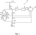
- the magnetic field sensor 10 shown in Figure 1 comprises an electrical energy source connector 12 for connecting the sensor 10 to a source of electrical energy (not shown) at voltage V, and an earth connector 14 for connecting the sensor 10 to earth or equivalent. Between the connectors 12 and 14, from the connector 12 to the connector 14, are two resistances R 1 and R 2 connected in series with one another, followed by two switches S 1 and S 2 also connected in series with one another.
- the interconnection 16 between the resistors R1 and R2 is connected to the input of an amplifier 18 the output from which is connected to the input of an analogue to digital converter 20, the output from which is connected to an input of a microprocessor 22 via a timer 24.
- An output 26 of the microprocessor 22 provides a digital output which can be connected to any other digital system, for example a meteorological system (not shown), or a navigation system (not shown).
- a magnetic sensing element 30 Connected across the interconnection 16 and the interconnection 28 between the switches S 1 and S 2 is a magnetic sensing element 30, via switches S 3 , S 4 , S 5 , and S 6 .
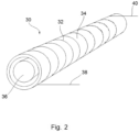
- the magnetic sensing element 30 comprises a coil 32 wound around and along a hollow cylindrical non-electrically conductive nonmagnetic former 34 within and along the interior of which extends a solid cylindrical core 36 of a ferromagnetic material such as iron.
- the coil has opposite ends 38 and 40 respectively connected to the interconnections (a) between switches S 3 and S 5 and (b) between switches S 4 and S 6 .
- One side of each of the switches S 3 and S 4 is connected to the interconnection 16, and the other sides of the switches S 3 and S 4 are connected respectively to the ends 38 and 40 of the coil 32.
- one side of each of the switches S 5 and S 6 is connected to the interconnection between the switches S 1 and S 2 , and the other sides of the switches S 5 and S 6 are connected respectively to the ends 38 and 40 of the coil 32.
- All the switches S 1 to S 6 are simple on-off switches connected to the microprocessor 22 for control thereby.
- the magnetic sensing element 30 is one of three (the other two of which are not shown) each mounted orthogonally relative to the other two, and each with circuitry as shown in Figure 1 but sharing a common microprocessor 22 which addresses the three elements cyclically. Signals from the three sensors taken together are used in a manner known in itself to provide an indication of the strength and direction of the ambient magnetic field, as described for example with reference to Figure 20 of US 5757184 .
- the microprocessor 22 sets switches S 2 , S 4 and S 5 closed, and switches S 3 , S 6 and S 1 open.
- switch S 2 remains closed and switch S 1 remains open, but the conditions of all the other switches S 3 to S 6 are reversed, so that simultaneously switches S 3 and S 6 are closed, and switches S 4 and S 5 are opened.
- time T 4 being a predetermined period after time T 3 equal to or about equal to the period between times T 0 and T 3 , the conditions of switches S 3 to S 6 remain unchanged, but the conditions of switches S 1 and S 2 are reversed, so that switch S 2 is opened and switch S 1 is closed.
- the negative current passing through the coil 32 steadily increases as more and more of the respective magnetic fields of the magnetic domains in the core 36 align themselves with the magnetic field generated within the coil 32 by the electrical current passing through it.
- the current is considered negative because of the direction of flow of the current through the coil at this stage, so that an increase in the negative current is indicated by a fall in the plot of current as a function of time in the graph shown in Figure 4 .
- the magnetisation of the core 36 is saturated, the negative electrical current increases at an even greater rate. The point in time at which this happens will be dependent upon the ambient magnetic field, because that field will itself cause a certain degree of alignment or anti-alignment of the magnetic fields of those domains.
- Figure 5 shows a graph of the voltage at the interconnection 16 plotted against time. Which of the steeper falls at the right hand side of the plot actually occurs again depends upon the strength and direction of the ambient magnetic field. Because of the linearity of the function, and the spacing between successive steep lines corresponding to equal increments of strength in the ambient magnetic field, it can be seen that the value of the voltage at a time passed by all the steep lines varies in proportion to the strength of that field, in fact in inverse proportion, so that the stronger the ambient magnetic field, the lower the measured voltage at that time.
- the actual times at which the voltage at interconnection 16 is made are at times T 1 and T 2 , respectively at equal periods of time ⁇ T after times T 0 and T 5 , respectively just before times T 3 and T 6 when the applied voltage is reversed.
- the period ⁇ T is stored in the timer 24, which is restarted on every occurrence of the times T 0 and T 5 in each cycle.
- the count in the timer 24 equals ⁇ T
- the value of the voltage at interconnection 16 is read by the microprocessor 22 from the input it receives from the analogue to digital converter 20.
- the microprocessor 22 then calculates the value of the difference between two successive readings.
- the magnitude of the difference between two successive readings gives the strength of the component of the ambient magnetic field which is in alignment with the axis of the coil 32, and the sign of the difference gives the direction of that component.
- the microprocessor 22 programmed in a manner known in itself to cause the display 26 to display the direction of North, being the direction in which the field is indicated to be strongest and of the appropriate sign, the sensor acts as a compass.
- the switches S 1 to S 6 , the resistors R 1 and R 2 , the amplifier 18 and the analogue to digital converter 20 could all be incorporated in the microprocessor 22.
Landscapes
- Physics & Mathematics (AREA)
- General Physics & Mathematics (AREA)
- Condensed Matter Physics & Semiconductors (AREA)
- Engineering & Computer Science (AREA)
- Radar, Positioning & Navigation (AREA)
- Remote Sensing (AREA)
- Measuring Magnetic Variables (AREA)
Description
- The present invention relates to a magnetic field sensor for determining the strength and/or direction of a component of an ambient magnetic field, comprising electrical circuitry which incorporates a magnetic sensing element, a voltmeter connected in the circuitry to provide a measure of the voltage across the magnetic sensing element, an electrical energy supply connector connected to the magnetic sensing element to supply an electrical current which passes through that element when the sensor is in use, and switches to reverse the direction of the flow of electrical current through the magnetic sensing element between successive measurements of the said voltage by the said voltmeter.
- In one such magnetic field sensor which has already been proposed, the magnetic sensing element comprises a flux meter in which the current is passed through a primary winding, and the voltage is measured across a secondary winding. This requires a measurement of peak voltages which is of limited accuracy.
-
US 2015/048820 A1 discloses compact, low power fluxgate magnetic sensor readout circuits and apparatus in which a demodulator or rectifier circuit modulates a sense signal from the fluxgate sense coil, and the demodulated signal is provided to an amplifier circuit with a transconductance or other amplifier and one or more feedback capacitors connected between the amplifier input and amplifier output to integrate the amplifier output current and provide a voltage output signal indicating the magnetic field sensed by the fluxgate sensor. -
EP 2075814 A discloses a magnetic flux measuring device and magnetic flux measuring method for stationary induction electrical apparatus which can accurately measure the magnetic flux without being influenced by the DC offset component which superimposes on the measurement system, and can constantly and continuously measure the magnetic flux without setting a limit in the magnetic flux measurement period. The magnetic flux measuring method which measures a magnetic flux of a stationary induction electrical apparatus using a voltage waveform of the stationary induction electrical apparatus, wherein the magnetic flux of the stationary induction electrical apparatus is determined by the steps of: inputting a voltage waveform of the stationary induction electrical apparatus into a negative-feedback amplification means of which feedback circuit is constructed by a low pass filter; and integrating output of the negative-feedback amplification means by integration means. -
US 2016/245878 A1 discloses a magnetic field measuring device including a first sensor unit which includes a first coil sensor configured to output a first sensor signal, a second sensor unit which includes a second coil sensor configured to output a second sensor signal and disposed in a direction perpendicular to the first coil sensor, a third sensor unit which includes a third coil sensor configured to output a third sensor signal and disposed in a direction perpendicular to the first and second coil sensors, and a digital signal processor outputs magnetic flux density based on a voltage difference between the first and fourth nodes, wherein the first to third sensor units respectively output first to third output signals in which specific voltages of the first to third sensor signals are maintained for a predetermined period of time. -
EP 0227888 A2 discloses a quick ranging technique controlled by a microcomputer, in which predetermined stepped adjustments are made to the charge times in a ranging circuit to bring the charge time into a required range, thereby minimising calibration time for an electronic compass; a digital filter also controlled by the microcomputer smooths out the magnetic field component signals. -
US 2013/214777 A1 discloses a semiconductor integrated circuit which includes a clock-signal control circuit controlling intensity-signal output, which is output from a signal processing circuit, to be stopped in at least a forward outage time and a backward outage time. The forward outage time is previous to an apex point of a triangular wave and having 1 to 5% of a triangular wave period. The backward outage time is subsequent to the apex point of the triangular wave and having 1 to 5% of a triangular wave period. -
US 5537038 A discloses a current of predetermined frequency which is fed to a coil wound around a ferromagnetic core through a fixed impedance means. A magnetic flux measurement is performed in terms of a level of a DC component of a voltage generated across the coil. A DC bias is added to the current of predetermined frequency, and the resultant current is applied through the fixed impedance means to the coil wound around the ferromagnetic core. A magnetic flux measurement is performed in terms of a level of a DC component of the voltage across the coil. A magnetic flux measuring method and apparatus for embodying the same have a high sensitivity in detecting a minute magnetic flux and an improved temperature characteristic because an output voltage little varies against a temperature variation. A magnetic flux measuring method and apparatus for embodying the same, when they are applied to a leakage flux flaw detection using a saturable magnetic flux sensor, is capable of expanding a measuring span of the magnetic flux sensor, thereby to improve a flaw detection performance. -
US2008/292044 A1 discloses a signal detection circuit comprising: a differential amplifier to which an output voltage of a detection coil of a magnetic sensor is to be applied; a comparator to output a digital signal being at one logic level in a period between two spike-shaped voltages adjacent to each other in the output voltage of the differential amplifier; and a count circuit to perform a count operation in a period during which the comparator outputs the digital signal of the one logic level, the count circuit including a first counter to count a first clock having a predetermined frequency, a second counter to count a second clock being equal in frequency to and different in phase from the first clock, the second counter having the same number of bits as the number of bits of the first counter, and an adder to add count values of the first and the second counter. -
US 9239365 B2 - Another magnetic field sensor is disclosed in
US 5757184 . In that sensor, a measurement is made of the time it takes for a response waveform to rise to a predetermined threshold, and this measurement also is of limited accuracy. - The present invention seeks to provide a remedy.
- Accordingly, a first aspect of the present invention is directed to a magnetic field sensor according to
claim 1. - The timer may be a part or parts of the processor, which may be a microprocessor. This enables economy of manufacture.
- The switches may be parts of the processor or microprocessor. Again, this affords an economy of parts in the manufacture of the sensor.
- The timer may be provided with a memory in which is retained the value of ΔT. Again, this affords an economy of parts.
- The voltmeter may comprise an amplifier connected in series with an analogue-to-digital converter between the magnetic sensing element and the processor or microprocessor, and the voltmeter may be made as an integral part or parts of the microprocessor, again for economy of parts.
- The present invention extends to a compass provided with a magnetic field sensor in accordance with the present invention.
- According to a second aspect of the present invention, there is provided a method of determining the strength and/or direction of a component of an ambient magnetic field, according to claim 8.
- The present invention extends to such a method using a sensor or a compass as set out in any one of the foregoing paragraphs between the one commencing "According to a first aspect" and the one commencing "According to a second aspect".
- Examples of a sensor, compass and method embodying the present invention will now be described in greater detail with reference to the accompanying drawings, in which:
-
Figure 1 shows a circuit diagram of a sensor embodying the present invention, -
Figure 2 shows a perspective end view of a magnetic sensing element of the circuitry shown inFigure 1 ; and -
Figures 3 to 5 show respective explanatory graphs. - The
magnetic field sensor 10 shown inFigure 1 comprises an electricalenergy source connector 12 for connecting thesensor 10 to a source of electrical energy (not shown) at voltage V, and anearth connector 14 for connecting thesensor 10 to earth or equivalent. Between theconnectors connector 12 to theconnector 14, are two resistances R1 and R2 connected in series with one another, followed by two switches S1 and S2 also connected in series with one another. - The
interconnection 16 between the resistors R1 and R2 is connected to the input of anamplifier 18 the output from which is connected to the input of an analogue todigital converter 20, the output from which is connected to an input of amicroprocessor 22 via atimer 24. Anoutput 26 of themicroprocessor 22 provides a digital output which can be connected to any other digital system, for example a meteorological system (not shown), or a navigation system (not shown). - Connected across the
interconnection 16 and theinterconnection 28 between the switches S1 and S2 is amagnetic sensing element 30, via switches S3, S4, S5, and S6. - As shown in
Figure 2 , themagnetic sensing element 30 comprises acoil 32 wound around and along a hollow cylindrical non-electrically conductive nonmagnetic former 34 within and along the interior of which extends a solidcylindrical core 36 of a ferromagnetic material such as iron. - The coil has
opposite ends interconnection 16, and the other sides of the switches S3 and S4 are connected respectively to theends coil 32. Similarly, one side of each of the switches S5 and S6 is connected to the interconnection between the switches S1 and S2, and the other sides of the switches S5 and S6 are connected respectively to theends coil 32. - All the switches S1 to S6 are simple on-off switches connected to the
microprocessor 22 for control thereby. - The
magnetic sensing element 30 is one of three (the other two of which are not shown) each mounted orthogonally relative to the other two, and each with circuitry as shown inFigure 1 but sharing acommon microprocessor 22 which addresses the three elements cyclically. Signals from the three sensors taken together are used in a manner known in itself to provide an indication of the strength and direction of the ambient magnetic field, as described for example with reference to Figure 20 ofUS 5757184 . - With the
connector 12 connected to a source of energy so that it is held at voltage V, at time T0 themicroprocessor 22 sets switches S2, S4 and S5 closed, and switches S3, S6 and S1 open. After a predetermined period of time set by themicroprocessor 22, at time T3, switch S2 remains closed and switch S1 remains open, but the conditions of all the other switches S3 to S6 are reversed, so that simultaneously switches S3 and S6 are closed, and switches S4 and S5 are opened. At time T4, being a predetermined period after time T3 equal to or about equal to the period between times T0 and T3, the conditions of switches S3 to S6 remain unchanged, but the conditions of switches S1 and S2 are reversed, so that switch S2 is opened and switch S1 is closed. - At time T5, being after time T4 by a period also about equal to that between times T0 and T3, the conditions of switches S3 to S6 again remain unchanged, but the conditions of the switches S1 and S2 are reversed again back to the condition they had between times T0 and T3.
- Upon completion of a further period after time T5, about the same as that between times T0 and T2, at time T6, the conditions of the switches S1 and S2 remain unaltered, but those of switches S3 to S6 are reversed back to the condition they had between times T0 and T3.
- Upon completion of a further such period after time T6, at time T7, the conditions of switches S3 to S6 remain unchanged, but those of switches S1 and S2 are once again reversed. Finally, after a further such period, the conditions of switches S3 to S6 remain unchanged, but the conditions of switches S1 and S2 are reversed to recommence this cycle of switching the switches S1 to S6.
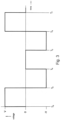
- It will be appreciated that the resulting voltage applied across the combination of resistor R1 and the
magnetic sensing element 30, with the direction of the voltage being dependent on the direction of this applied voltage relative to thecoil 32, is as shown inFigure 3 . - During successive cycles, the current flowing through the
coil 32 is as shown inFigure 4 . Which of the troughs and peaks shown at times T3 and T6 actually occurs, at around the time when the direction of applied voltage is reversed, depends upon the strength and direction of the ambient magnetic field. - Thus, during the period from T0 to T3, the negative current passing through the
coil 32 steadily increases as more and more of the respective magnetic fields of the magnetic domains in thecore 36 align themselves with the magnetic field generated within thecoil 32 by the electrical current passing through it. The current is considered negative because of the direction of flow of the current through the coil at this stage, so that an increase in the negative current is indicated by a fall in the plot of current as a function of time in the graph shown inFigure 4 . When the magnetisation of thecore 36 is saturated, the negative electrical current increases at an even greater rate. The point in time at which this happens will be dependent upon the ambient magnetic field, because that field will itself cause a certain degree of alignment or anti-alignment of the magnetic fields of those domains. - At the time T3, the direction of the current through the
coil 32 is reversed, and the plot of current against time reverses so that the plot of current versus time at this stage is more or less symmetrical about time T3. This is so until the magnetic energy stored in thecore 36 is almost zero at time T4 when the ends of thecoil 32 are connected across the resistor R2 to completely remove the energy at which point the current passing through thecoil 32 is zero. - The next half of the cycle of switching results in a similar process but with the current passing in a positive direction through the
coil 32, so that the plot of current versus time in the right-hand side ofFigure 4 is a vertical inversion of the plot of current versus time in the left-hand side of that Figure. However, for any non-zero value of the ambient magnetic field, it will be appreciated that the size of the negative peak and the positive peak at times T3 and T6 will be different for any actual plot of current versus time. In other words, the time it takes for saturation of the core 36 to be reached will be different for one direction of current flow than it is for the opposite direction of current flow. -
Figure 5 shows a graph of the voltage at theinterconnection 16 plotted against time. Which of the steeper falls at the right hand side of the plot actually occurs again depends upon the strength and direction of the ambient magnetic field. Because of the linearity of the function, and the spacing between successive steep lines corresponding to equal increments of strength in the ambient magnetic field, it can be seen that the value of the voltage at a time passed by all the steep lines varies in proportion to the strength of that field, in fact in inverse proportion, so that the stronger the ambient magnetic field, the lower the measured voltage at that time. - The actual times at which the voltage at
interconnection 16 is made are at times T1 and T2, respectively at equal periods of time ΔT after times T0 and T5, respectively just before times T3 and T6 when the applied voltage is reversed. - The period ΔT is stored in the
timer 24, which is restarted on every occurrence of the times T0 and T5 in each cycle. When the count in thetimer 24 equals ΔT, the value of the voltage atinterconnection 16 is read by themicroprocessor 22 from the input it receives from the analogue todigital converter 20. Themicroprocessor 22 then calculates the value of the difference between two successive readings. The magnitude of the difference between two successive readings gives the strength of the component of the ambient magnetic field which is in alignment with the axis of thecoil 32, and the sign of the difference gives the direction of that component. - With measurements from the three mutually orthogonal
magnetic sensing elements 30, themicroprocessor 22 programmed in a manner known in itself to cause thedisplay 26 to display the direction of North, being the direction in which the field is indicated to be strongest and of the appropriate sign, the sensor acts as a compass. - Numerous variations and modifications to the illustrated sensor may occur to the reader without taking the resulting construction outside the scope of the present invention. For example, the switches S1 to S6, the resistors R1 and R2, the
amplifier 18 and the analogue todigital converter 20 could all be incorporated in themicroprocessor 22.
Claims (9)
- A magnetic field sensor (10) for determining the strength and/or direction of a component of an ambient magnetic field, comprising electrical circuitry which incorporates:a magnetic sensing element (30) comprising a coil (32) surrounding magnetic material (36),a voltmeter (22) connected in the circuitry to provide a measure of the voltage across the magnetic sensing element (30),an electrical energy source connector (12) connected to the magnetic sensing element (30) to supply an electrical current which passes through that element (30) when the sensor (10) is in use, andswitches (S3, S4, S5 and S6) to reverse the direction of the flow of electrical current through the magnetic sensing element (30) between successive measurements of the said voltage by the said voltmeter (22), the electrical energy source connector (12) and the said switches (S3, S4, S5 and S6) being connected to the said coil (32),wherein the voltmeter (22) is connected to measure the voltage across the said coil (32), and the circuitry further comprises a timer (24) connected within the circuitry to cause the voltmeter (22) to provide measurements V1 and V2 respectively at times T1 and T2 which occur during saturation of the magnetic material (36) after successive operations of the switches (S3, S4, S5 and S6) respectively at times T0 and T5, to initiate the passage of electrical current through the coil (32) in respective opposite directions, such that T1 - T0 = T2 - T5 = ΔT, where ΔT is a predetermined period of time, and a processor (22) is connected in the circuitry to provide an indication of the value of V1-V2, the magnitude of which provides an indication of the strength of the said component, and the sign of which provides an indication of the direction of the said component.
- A magnetic field sensor (10) according to claim 1, wherein the timer (24) is a part or parts of the processor (22), especially but not exclusively a microprocessor.
- A magnetic field sensor according to claim 1 or claim 2, wherein the switches (S3, S4, S5 and S6) are parts of the processor (22) or microprocessor.
- A magnetic field sensor (10) according to any preceding claim, wherein the voltmeter (22) is a part or parts of the processor (22) or microprocessor.
- A magnetic field sensor (10) according to any preceding claim, wherein the timer (24) is provided with a memory in which is retained the value of ΔT.
- A magnetic field sensor (10) according to any preceding claim, wherein the voltmeter (22) comprises an amplifier (18) connected in series with an analogue-to-digital converter (20) between the magnetic sensing element (30) and the processor (22) or microprocessor.
- A compass provided with a magnetic field sensor (10) as claimed in any preceding claim.
- A method of determining the strength and/or direction of a component of an ambient magnetic field, comprising obtaining a measure of the voltage V1 across a magnetic sensing element (30), in the form of a coil (32) surrounding magnetic material (36), of electrical circuitry of a magnetic field sensor (10) by means of a voltmeter (22) of the electrical circuitry at a time T1 during saturation of the magnetic material (36) after a time T0 when an electrical current through the coil in a first direction is initiated by switches (S1 to S6) of the circuitry, using a timer (24) to equate T1-T0 to a predetermined period ΔT, and obtaining a measure of the voltage V2 across the coil at a time T2 also during saturation of the magnetic material (36) after a time T5 when an electrical current through the coil in the direction opposite to the said first direction is initiated by the switches (S3, S4, S5 and S6), equating T2-T5 to the predetermined period ΔT, and using a processor (22) of the circuitry to provide an indication of the value of V1-V2, the magnitude of which provides an indication of the strength of the said component, and the sign of which provides an indication of the direction of the said component.
- A method of determining the strength and/or direction of a component of an ambient magnetic field, using a magnetic field sensor (10) as claimed in any one of claims 2 to 7 according to the method of claim 8.
Applications Claiming Priority (2)
| Application Number | Priority Date | Filing Date | Title |
|---|---|---|---|
| GBGB1701297.2A GB201701297D0 (en) | 2017-01-26 | 2017-01-26 | A magnetic field sensor |
| PCT/EP2017/025373 WO2018137750A1 (en) | 2017-01-26 | 2017-12-27 | A magnetic field sensor |
Publications (3)
| Publication Number | Publication Date |
|---|---|
| EP3574334A1 EP3574334A1 (en) | 2019-12-04 |
| EP3574334B1 true EP3574334B1 (en) | 2023-08-09 |
| EP3574334C0 EP3574334C0 (en) | 2023-08-09 |
Family
ID=58462876
Family Applications (1)
| Application Number | Title | Priority Date | Filing Date |
|---|---|---|---|
| EP17837855.0A Active EP3574334B1 (en) | 2017-01-26 | 2017-12-27 | A magnetic field sensor |
Country Status (5)
| Country | Link |
|---|---|
| US (1) | US11480633B2 (en) |
| EP (1) | EP3574334B1 (en) |
| CA (1) | CA3056154A1 (en) |
| GB (2) | GB201701297D0 (en) |
| WO (1) | WO2018137750A1 (en) |
Family Cites Families (16)
| Publication number | Priority date | Publication date | Assignee | Title |
|---|---|---|---|---|
| US239365A (en) | 1881-03-29 | John w | ||
| US537038A (en) | 1895-04-09 | Safety check-valve for steam-boilers | ||
| US4750349A (en) | 1985-12-27 | 1988-06-14 | Chrysler Motors Corporation | Microcomputer controlled quick ranging technique and digital filter |
| DE3704934A1 (en) * | 1987-02-17 | 1988-08-25 | Wellhausen Heinz | ELECTRONIC COMPASS WITH DIRECTIONAL MAGNETIC SENSORS |
| US5537038A (en) * | 1988-12-15 | 1996-07-16 | Nkk Corporation | Magnetic flux measuring method and apparatus for detecting high frequency components of magnetic flux with high speed orientation |
| US5091697A (en) * | 1989-07-31 | 1992-02-25 | Ii Morrow, Inc. | Low power, high accuracy magnetometer and magnetic field strength measurement method |
| JPH09152473A (en) | 1995-09-29 | 1997-06-10 | Sony Corp | Magnetic detector |
| JP5044188B2 (en) | 2006-10-16 | 2012-10-10 | 株式会社東芝 | Magnetic flux measuring device for static induction electrical equipment, magnetic flux measuring method, and synchronous switching control device for circuit breaker |
| JP2008292325A (en) | 2007-05-24 | 2008-12-04 | Sanyo Electric Co Ltd | Signal detection circuit |
| EP2108966A1 (en) * | 2008-04-08 | 2009-10-14 | Ecole Polytechnique Fédérale de Lausanne (EPFL) | Current sensor and assembly group for current measurement |
| JP5518661B2 (en) * | 2010-09-30 | 2014-06-11 | 株式会社フジクラ | Semiconductor integrated circuit, magnetic detector, electronic compass |
| JP5364816B1 (en) * | 2012-06-08 | 2013-12-11 | 株式会社フジクラ | Magnetic element control device, magnetic element control method, and magnetic detection device |
| JP2014071101A (en) | 2012-10-02 | 2014-04-21 | Fujikura Ltd | Signal processing circuit and magnetic field detection device using the same |
| JP6014544B2 (en) | 2013-05-13 | 2016-10-25 | 株式会社フジクラ | Inspection circuit for magnetic field detection device and inspection method thereof |
| US9261571B2 (en) * | 2013-08-15 | 2016-02-16 | Texas Instruments Incorporated | Fluxgate magnetic sensor readout apparatus |
| KR101873855B1 (en) | 2015-02-23 | 2018-07-03 | 한국전자통신연구원 | Triaxial sensor and device including the same for measuring magnetic field |
-
2017
- 2017-01-26 GB GBGB1701297.2A patent/GB201701297D0/en not_active Ceased
- 2017-12-27 GB GB1909050.5A patent/GB2572509A/en not_active Withdrawn
- 2017-12-27 CA CA3056154A patent/CA3056154A1/en active Pending
- 2017-12-27 EP EP17837855.0A patent/EP3574334B1/en active Active
- 2017-12-27 WO PCT/EP2017/025373 patent/WO2018137750A1/en not_active Ceased
- 2017-12-27 US US16/493,000 patent/US11480633B2/en active Active
Also Published As
| Publication number | Publication date |
|---|---|
| WO2018137750A1 (en) | 2018-08-02 |
| CA3056154A1 (en) | 2018-08-02 |
| EP3574334A1 (en) | 2019-12-04 |
| GB2572509A (en) | 2019-10-02 |
| US20200064415A1 (en) | 2020-02-27 |
| GB201909050D0 (en) | 2019-08-07 |
| US11480633B2 (en) | 2022-10-25 |
| EP3574334C0 (en) | 2023-08-09 |
| GB201701297D0 (en) | 2017-03-15 |
Similar Documents
| Publication | Publication Date | Title |
|---|---|---|
| US5811965A (en) | DC and AC current sensor having a minor-loop operated current transformer | |
| KR100993928B1 (en) | Magnetic bridge type current sensor, magnetic bridge type current detection method, and magnetic bridge used in the sensor and detection method | |
| US20140021939A1 (en) | Current-measuring device | |
| KR20040081200A (en) | Magnetic field sensor | |
| US20160290842A1 (en) | Method for Operating a Magneto-Inductive Measuring System | |
| EP3105602B1 (en) | Sensor and method for electric current measurement | |
| JP2009186433A (en) | Eddy current sample measurement method, eddy current sensor, and eddy current sample measurement system | |
| US3002383A (en) | Electromagnetic induction flowmeter | |
| CN114966159B (en) | Current sensor for contactless current measurement | |
| EP3574334B1 (en) | A magnetic field sensor | |
| WO2016158096A1 (en) | Differential magnetic sensor | |
| US4059796A (en) | Second harmonic magnetic field detection circuit with means to rectify the sensed signal | |
| JP4716030B2 (en) | Current sensor | |
| EP3255445B1 (en) | Magneto-impedance (mi) magnetic sensor | |
| JP2007033222A (en) | Current sensor | |
| JP2002286821A (en) | Magnetic field detector | |
| RU2784211C1 (en) | Highly sensitive magnetoimpedance sensor of gradient magnetic fields | |
| JPH0224476B2 (en) | ||
| JP2003004830A (en) | Magnetic field detector | |
| RU1830135C (en) | Electromagnetic flowmeter | |
| RU2149418C1 (en) | Digital device for measuring intensity of magnetic field | |
| JPH03243801A (en) | Non-contact distance meter | |
| JP2002006016A (en) | Magnetic sensor | |
| JPH01308982A (en) | Method and apparatus for measuring magnetism | |
| US20060192549A1 (en) | Current sensor with magnetic toroid dual frequency detection scheme |
Legal Events
| Date | Code | Title | Description |
|---|---|---|---|
| STAA | Information on the status of an ep patent application or granted ep patent |
Free format text: STATUS: UNKNOWN |
|
| STAA | Information on the status of an ep patent application or granted ep patent |
Free format text: STATUS: THE INTERNATIONAL PUBLICATION HAS BEEN MADE |
|
| PUAI | Public reference made under article 153(3) epc to a published international application that has entered the european phase |
Free format text: ORIGINAL CODE: 0009012 |
|
| STAA | Information on the status of an ep patent application or granted ep patent |
Free format text: STATUS: REQUEST FOR EXAMINATION WAS MADE |
|
| 17P | Request for examination filed |
Effective date: 20190826 |
|
| AK | Designated contracting states |
Kind code of ref document: A1 Designated state(s): AL AT BE BG CH CY CZ DE DK EE ES FI FR GB GR HR HU IE IS IT LI LT LU LV MC MK MT NL NO PL PT RO RS SE SI SK SM TR |
|
| AX | Request for extension of the european patent |
Extension state: BA ME |
|
| DAV | Request for validation of the european patent (deleted) | ||
| DAX | Request for extension of the european patent (deleted) | ||
| STAA | Information on the status of an ep patent application or granted ep patent |
Free format text: STATUS: EXAMINATION IS IN PROGRESS |
|
| 17Q | First examination report despatched |
Effective date: 20220121 |
|
| GRAP | Despatch of communication of intention to grant a patent |
Free format text: ORIGINAL CODE: EPIDOSNIGR1 |
|
| STAA | Information on the status of an ep patent application or granted ep patent |
Free format text: STATUS: GRANT OF PATENT IS INTENDED |
|
| INTG | Intention to grant announced |
Effective date: 20230327 |
|
| GRAS | Grant fee paid |
Free format text: ORIGINAL CODE: EPIDOSNIGR3 |
|
| GRAA | (expected) grant |
Free format text: ORIGINAL CODE: 0009210 |
|
| STAA | Information on the status of an ep patent application or granted ep patent |
Free format text: STATUS: THE PATENT HAS BEEN GRANTED |
|
| RAP3 | Party data changed (applicant data changed or rights of an application transferred) |
Owner name: GILL CORPORATE LIMITED |
|
| AK | Designated contracting states |
Kind code of ref document: B1 Designated state(s): AL AT BE BG CH CY CZ DE DK EE ES FI FR GB GR HR HU IE IS IT LI LT LU LV MC MK MT NL NO PL PT RO RS SE SI SK SM TR |
|
| REG | Reference to a national code |
Ref country code: GB Ref legal event code: FG4D |
|
| REG | Reference to a national code |
Ref country code: CH Ref legal event code: EP |
|
| REG | Reference to a national code |
Ref country code: DE Ref legal event code: R096 Ref document number: 602017072578 Country of ref document: DE |
|
| REG | Reference to a national code |
Ref country code: IE Ref legal event code: FG4D |
|
| U01 | Request for unitary effect filed |
Effective date: 20230823 |
|
| U07 | Unitary effect registered |
Designated state(s): AT BE BG DE DK EE FI FR IT LT LU LV MT NL PT SE SI Effective date: 20230829 |
|
| PG25 | Lapsed in a contracting state [announced via postgrant information from national office to epo] |
Ref country code: GR Free format text: LAPSE BECAUSE OF FAILURE TO SUBMIT A TRANSLATION OF THE DESCRIPTION OR TO PAY THE FEE WITHIN THE PRESCRIBED TIME-LIMIT Effective date: 20231110 |
|
| PG25 | Lapsed in a contracting state [announced via postgrant information from national office to epo] |
Ref country code: IS Free format text: LAPSE BECAUSE OF FAILURE TO SUBMIT A TRANSLATION OF THE DESCRIPTION OR TO PAY THE FEE WITHIN THE PRESCRIBED TIME-LIMIT Effective date: 20231209 |
|
| U20 | Renewal fee for the european patent with unitary effect paid |
Year of fee payment: 7 Effective date: 20231215 |
|
| PG25 | Lapsed in a contracting state [announced via postgrant information from national office to epo] |
Ref country code: RS Free format text: LAPSE BECAUSE OF FAILURE TO SUBMIT A TRANSLATION OF THE DESCRIPTION OR TO PAY THE FEE WITHIN THE PRESCRIBED TIME-LIMIT Effective date: 20230809 Ref country code: NO Free format text: LAPSE BECAUSE OF FAILURE TO SUBMIT A TRANSLATION OF THE DESCRIPTION OR TO PAY THE FEE WITHIN THE PRESCRIBED TIME-LIMIT Effective date: 20231109 Ref country code: IS Free format text: LAPSE BECAUSE OF FAILURE TO SUBMIT A TRANSLATION OF THE DESCRIPTION OR TO PAY THE FEE WITHIN THE PRESCRIBED TIME-LIMIT Effective date: 20231209 Ref country code: HR Free format text: LAPSE BECAUSE OF FAILURE TO SUBMIT A TRANSLATION OF THE DESCRIPTION OR TO PAY THE FEE WITHIN THE PRESCRIBED TIME-LIMIT Effective date: 20230809 Ref country code: GR Free format text: LAPSE BECAUSE OF FAILURE TO SUBMIT A TRANSLATION OF THE DESCRIPTION OR TO PAY THE FEE WITHIN THE PRESCRIBED TIME-LIMIT Effective date: 20231110 |
|
| PG25 | Lapsed in a contracting state [announced via postgrant information from national office to epo] |
Ref country code: PL Free format text: LAPSE BECAUSE OF FAILURE TO SUBMIT A TRANSLATION OF THE DESCRIPTION OR TO PAY THE FEE WITHIN THE PRESCRIBED TIME-LIMIT Effective date: 20230809 |
|
| PG25 | Lapsed in a contracting state [announced via postgrant information from national office to epo] |
Ref country code: ES Free format text: LAPSE BECAUSE OF FAILURE TO SUBMIT A TRANSLATION OF THE DESCRIPTION OR TO PAY THE FEE WITHIN THE PRESCRIBED TIME-LIMIT Effective date: 20230809 |
|
| PG25 | Lapsed in a contracting state [announced via postgrant information from national office to epo] |
Ref country code: SM Free format text: LAPSE BECAUSE OF FAILURE TO SUBMIT A TRANSLATION OF THE DESCRIPTION OR TO PAY THE FEE WITHIN THE PRESCRIBED TIME-LIMIT Effective date: 20230809 Ref country code: RO Free format text: LAPSE BECAUSE OF FAILURE TO SUBMIT A TRANSLATION OF THE DESCRIPTION OR TO PAY THE FEE WITHIN THE PRESCRIBED TIME-LIMIT Effective date: 20230809 Ref country code: ES Free format text: LAPSE BECAUSE OF FAILURE TO SUBMIT A TRANSLATION OF THE DESCRIPTION OR TO PAY THE FEE WITHIN THE PRESCRIBED TIME-LIMIT Effective date: 20230809 Ref country code: CZ Free format text: LAPSE BECAUSE OF FAILURE TO SUBMIT A TRANSLATION OF THE DESCRIPTION OR TO PAY THE FEE WITHIN THE PRESCRIBED TIME-LIMIT Effective date: 20230809 Ref country code: SK Free format text: LAPSE BECAUSE OF FAILURE TO SUBMIT A TRANSLATION OF THE DESCRIPTION OR TO PAY THE FEE WITHIN THE PRESCRIBED TIME-LIMIT Effective date: 20230809 |
|
| REG | Reference to a national code |
Ref country code: DE Ref legal event code: R097 Ref document number: 602017072578 Country of ref document: DE |
|
| PLBE | No opposition filed within time limit |
Free format text: ORIGINAL CODE: 0009261 |
|
| STAA | Information on the status of an ep patent application or granted ep patent |
Free format text: STATUS: NO OPPOSITION FILED WITHIN TIME LIMIT |
|
| 26N | No opposition filed |
Effective date: 20240513 |
|
| REG | Reference to a national code |
Ref country code: CH Ref legal event code: PL |
|
| PG25 | Lapsed in a contracting state [announced via postgrant information from national office to epo] |
Ref country code: MC Free format text: LAPSE BECAUSE OF FAILURE TO SUBMIT A TRANSLATION OF THE DESCRIPTION OR TO PAY THE FEE WITHIN THE PRESCRIBED TIME-LIMIT Effective date: 20230809 |
|
| PG25 | Lapsed in a contracting state [announced via postgrant information from national office to epo] |
Ref country code: MC Free format text: LAPSE BECAUSE OF FAILURE TO SUBMIT A TRANSLATION OF THE DESCRIPTION OR TO PAY THE FEE WITHIN THE PRESCRIBED TIME-LIMIT Effective date: 20230809 |
|
| REG | Reference to a national code |
Ref country code: IE Ref legal event code: MM4A |
|
| PG25 | Lapsed in a contracting state [announced via postgrant information from national office to epo] |
Ref country code: IE Free format text: LAPSE BECAUSE OF NON-PAYMENT OF DUE FEES Effective date: 20231227 |
|
| PG25 | Lapsed in a contracting state [announced via postgrant information from national office to epo] |
Ref country code: CH Free format text: LAPSE BECAUSE OF NON-PAYMENT OF DUE FEES Effective date: 20231231 |
|
| PG25 | Lapsed in a contracting state [announced via postgrant information from national office to epo] |
Ref country code: IE Free format text: LAPSE BECAUSE OF NON-PAYMENT OF DUE FEES Effective date: 20231227 Ref country code: CH Free format text: LAPSE BECAUSE OF NON-PAYMENT OF DUE FEES Effective date: 20231231 |
|
| U20 | Renewal fee for the european patent with unitary effect paid |
Year of fee payment: 8 Effective date: 20241216 |
|
| U1N | Appointed representative for the unitary patent procedure changed after the registration of the unitary effect |
Representative=s name: ABEL & IMRAY LLP; GB |
|
| PG25 | Lapsed in a contracting state [announced via postgrant information from national office to epo] |
Ref country code: CY Free format text: LAPSE BECAUSE OF FAILURE TO SUBMIT A TRANSLATION OF THE DESCRIPTION OR TO PAY THE FEE WITHIN THE PRESCRIBED TIME-LIMIT; INVALID AB INITIO Effective date: 20171227 |
|
| PG25 | Lapsed in a contracting state [announced via postgrant information from national office to epo] |
Ref country code: HU Free format text: LAPSE BECAUSE OF FAILURE TO SUBMIT A TRANSLATION OF THE DESCRIPTION OR TO PAY THE FEE WITHIN THE PRESCRIBED TIME-LIMIT; INVALID AB INITIO Effective date: 20171227 |
|
| PG25 | Lapsed in a contracting state [announced via postgrant information from national office to epo] |
Ref country code: TR Free format text: LAPSE BECAUSE OF FAILURE TO SUBMIT A TRANSLATION OF THE DESCRIPTION OR TO PAY THE FEE WITHIN THE PRESCRIBED TIME-LIMIT Effective date: 20230809 |
|
| PGFP | Annual fee paid to national office [announced via postgrant information from national office to epo] |
Ref country code: GB Payment date: 20251230 Year of fee payment: 9 |
|
| U20 | Renewal fee for the european patent with unitary effect paid |
Year of fee payment: 9 Effective date: 20251230 |