EP3574313B1 - Sensor - Google Patents
Sensor Download PDFInfo
- Publication number
- EP3574313B1 EP3574313B1 EP18702467.4A EP18702467A EP3574313B1 EP 3574313 B1 EP3574313 B1 EP 3574313B1 EP 18702467 A EP18702467 A EP 18702467A EP 3574313 B1 EP3574313 B1 EP 3574313B1
- Authority
- EP
- European Patent Office
- Prior art keywords
- heating element
- wire
- core
- fluid
- previous
- Prior art date
- Legal status (The legal status is an assumption and is not a legal conclusion. Google has not performed a legal analysis and makes no representation as to the accuracy of the status listed.)
- Active
Links
Images

Classifications
-
- G—PHYSICS
- G01—MEASURING; TESTING
- G01N—INVESTIGATING OR ANALYSING MATERIALS BY DETERMINING THEIR CHEMICAL OR PHYSICAL PROPERTIES
- G01N33/00—Investigating or analysing materials by specific methods not covered by groups G01N1/00 - G01N31/00
- G01N33/48—Biological material, e.g. blood, urine; Haemocytometers
- G01N33/50—Chemical analysis of biological material, e.g. blood, urine; Testing involving biospecific ligand binding methods; Immunological testing
- G01N33/53—Immunoassay; Biospecific binding assay; Materials therefor
- G01N33/543—Immunoassay; Biospecific binding assay; Materials therefor with an insoluble carrier for immobilising immunochemicals
-
- G—PHYSICS
- G01—MEASURING; TESTING
- G01N—INVESTIGATING OR ANALYSING MATERIALS BY DETERMINING THEIR CHEMICAL OR PHYSICAL PROPERTIES
- G01N25/00—Investigating or analyzing materials by the use of thermal means
- G01N25/20—Investigating or analyzing materials by the use of thermal means by investigating the development of heat, i.e. calorimetry, e.g. by measuring specific heat, by measuring thermal conductivity
- G01N25/48—Investigating or analyzing materials by the use of thermal means by investigating the development of heat, i.e. calorimetry, e.g. by measuring specific heat, by measuring thermal conductivity on solution, sorption, or a chemical reaction not involving combustion or catalytic oxidation
- G01N25/4873—Investigating or analyzing materials by the use of thermal means by investigating the development of heat, i.e. calorimetry, e.g. by measuring specific heat, by measuring thermal conductivity on solution, sorption, or a chemical reaction not involving combustion or catalytic oxidation for a flowing, e.g. gas sample
-
- G—PHYSICS
- G01—MEASURING; TESTING
- G01N—INVESTIGATING OR ANALYSING MATERIALS BY DETERMINING THEIR CHEMICAL OR PHYSICAL PROPERTIES
- G01N33/00—Investigating or analysing materials by specific methods not covered by groups G01N1/00 - G01N31/00
- G01N33/48—Biological material, e.g. blood, urine; Haemocytometers
- G01N33/50—Chemical analysis of biological material, e.g. blood, urine; Testing involving biospecific ligand binding methods; Immunological testing
- G01N33/53—Immunoassay; Biospecific binding assay; Materials therefor
- G01N33/5308—Immunoassay; Biospecific binding assay; Materials therefor for analytes not provided for elsewhere, e.g. nucleic acids, uric acid, worms, mites
-
- G—PHYSICS
- G01—MEASURING; TESTING
- G01N—INVESTIGATING OR ANALYSING MATERIALS BY DETERMINING THEIR CHEMICAL OR PHYSICAL PROPERTIES
- G01N33/00—Investigating or analysing materials by specific methods not covered by groups G01N1/00 - G01N31/00
- G01N33/48—Biological material, e.g. blood, urine; Haemocytometers
- G01N33/50—Chemical analysis of biological material, e.g. blood, urine; Testing involving biospecific ligand binding methods; Immunological testing
- G01N33/53—Immunoassay; Biospecific binding assay; Materials therefor
- G01N33/543—Immunoassay; Biospecific binding assay; Materials therefor with an insoluble carrier for immobilising immunochemicals
- G01N33/54353—Immunoassay; Biospecific binding assay; Materials therefor with an insoluble carrier for immobilising immunochemicals with ligand attached to the carrier via a chemical coupling agent
-
- G—PHYSICS
- G01—MEASURING; TESTING
- G01N—INVESTIGATING OR ANALYSING MATERIALS BY DETERMINING THEIR CHEMICAL OR PHYSICAL PROPERTIES
- G01N33/00—Investigating or analysing materials by specific methods not covered by groups G01N1/00 - G01N31/00
- G01N33/48—Biological material, e.g. blood, urine; Haemocytometers
- G01N33/50—Chemical analysis of biological material, e.g. blood, urine; Testing involving biospecific ligand binding methods; Immunological testing
- G01N33/53—Immunoassay; Biospecific binding assay; Materials therefor
- G01N33/543—Immunoassay; Biospecific binding assay; Materials therefor with an insoluble carrier for immobilising immunochemicals
- G01N33/54366—Apparatus specially adapted for solid-phase testing
- G01N33/54373—Apparatus specially adapted for solid-phase testing involving physiochemical end-point determination, e.g. wave-guides, FETS, gratings
- G01N33/5438—Electrodes
-
- G—PHYSICS
- G01—MEASURING; TESTING
- G01N—INVESTIGATING OR ANALYSING MATERIALS BY DETERMINING THEIR CHEMICAL OR PHYSICAL PROPERTIES
- G01N33/00—Investigating or analysing materials by specific methods not covered by groups G01N1/00 - G01N31/00
- G01N33/48—Biological material, e.g. blood, urine; Haemocytometers
- G01N33/50—Chemical analysis of biological material, e.g. blood, urine; Testing involving biospecific ligand binding methods; Immunological testing
- G01N33/53—Immunoassay; Biospecific binding assay; Materials therefor
- G01N33/543—Immunoassay; Biospecific binding assay; Materials therefor with an insoluble carrier for immobilising immunochemicals
- G01N33/54393—Improving reaction conditions or stability, e.g. by coating or irradiation of surface, by reduction of non-specific binding, by promotion of specific binding
-
- G—PHYSICS
- G01—MEASURING; TESTING
- G01N—INVESTIGATING OR ANALYSING MATERIALS BY DETERMINING THEIR CHEMICAL OR PHYSICAL PROPERTIES
- G01N33/00—Investigating or analysing materials by specific methods not covered by groups G01N1/00 - G01N31/00
- G01N33/48—Biological material, e.g. blood, urine; Haemocytometers
- G01N33/50—Chemical analysis of biological material, e.g. blood, urine; Testing involving biospecific ligand binding methods; Immunological testing
- G01N33/53—Immunoassay; Biospecific binding assay; Materials therefor
- G01N33/543—Immunoassay; Biospecific binding assay; Materials therefor with an insoluble carrier for immobilising immunochemicals
- G01N33/551—Immunoassay; Biospecific binding assay; Materials therefor with an insoluble carrier for immobilising immunochemicals the carrier being inorganic
- G01N33/553—Metal or metal coated
-
- G—PHYSICS
- G01—MEASURING; TESTING
- G01N—INVESTIGATING OR ANALYSING MATERIALS BY DETERMINING THEIR CHEMICAL OR PHYSICAL PROPERTIES
- G01N33/00—Investigating or analysing materials by specific methods not covered by groups G01N1/00 - G01N31/00
- G01N33/48—Biological material, e.g. blood, urine; Haemocytometers
- G01N33/50—Chemical analysis of biological material, e.g. blood, urine; Testing involving biospecific ligand binding methods; Immunological testing
- G01N33/74—Chemical analysis of biological material, e.g. blood, urine; Testing involving biospecific ligand binding methods; Immunological testing involving hormones or other non-cytokine intercellular protein regulatory factors such as growth factors, including receptors to hormones and growth factors
-
- G—PHYSICS
- G01—MEASURING; TESTING
- G01N—INVESTIGATING OR ANALYSING MATERIALS BY DETERMINING THEIR CHEMICAL OR PHYSICAL PROPERTIES
- G01N33/00—Investigating or analysing materials by specific methods not covered by groups G01N1/00 - G01N31/00
- G01N33/48—Biological material, e.g. blood, urine; Haemocytometers
- G01N33/50—Chemical analysis of biological material, e.g. blood, urine; Testing involving biospecific ligand binding methods; Immunological testing
- G01N33/94—Chemical analysis of biological material, e.g. blood, urine; Testing involving biospecific ligand binding methods; Immunological testing involving narcotics or drugs or pharmaceuticals, neurotransmitters or associated receptors
- G01N33/9446—Antibacterials
-
- C—CHEMISTRY; METALLURGY
- C12—BIOCHEMISTRY; BEER; SPIRITS; WINE; VINEGAR; MICROBIOLOGY; ENZYMOLOGY; MUTATION OR GENETIC ENGINEERING
- C12Q—MEASURING OR TESTING PROCESSES INVOLVING ENZYMES, NUCLEIC ACIDS OR MICROORGANISMS; COMPOSITIONS OR TEST PAPERS THEREFOR; PROCESSES OF PREPARING SUCH COMPOSITIONS; CONDITION-RESPONSIVE CONTROL IN MICROBIOLOGICAL OR ENZYMOLOGICAL PROCESSES
- C12Q1/00—Measuring or testing processes involving enzymes, nucleic acids or microorganisms; Compositions therefor; Processes of preparing such compositions
- C12Q1/68—Measuring or testing processes involving enzymes, nucleic acids or microorganisms; Compositions therefor; Processes of preparing such compositions involving nucleic acids
- C12Q1/6813—Hybridisation assays
- C12Q1/6816—Hybridisation assays characterised by the detection means
- C12Q1/6825—Nucleic acid detection involving sensors
-
- C—CHEMISTRY; METALLURGY
- C12—BIOCHEMISTRY; BEER; SPIRITS; WINE; VINEGAR; MICROBIOLOGY; ENZYMOLOGY; MUTATION OR GENETIC ENGINEERING
- C12Q—MEASURING OR TESTING PROCESSES INVOLVING ENZYMES, NUCLEIC ACIDS OR MICROORGANISMS; COMPOSITIONS OR TEST PAPERS THEREFOR; PROCESSES OF PREPARING SUCH COMPOSITIONS; CONDITION-RESPONSIVE CONTROL IN MICROBIOLOGICAL OR ENZYMOLOGICAL PROCESSES
- C12Q1/00—Measuring or testing processes involving enzymes, nucleic acids or microorganisms; Compositions therefor; Processes of preparing such compositions
- C12Q1/68—Measuring or testing processes involving enzymes, nucleic acids or microorganisms; Compositions therefor; Processes of preparing such compositions involving nucleic acids
- C12Q1/6813—Hybridisation assays
- C12Q1/6834—Enzymatic or biochemical coupling of nucleic acids to a solid phase
- C12Q1/6837—Enzymatic or biochemical coupling of nucleic acids to a solid phase using probe arrays or probe chips
-
- G—PHYSICS
- G01—MEASURING; TESTING
- G01N—INVESTIGATING OR ANALYSING MATERIALS BY DETERMINING THEIR CHEMICAL OR PHYSICAL PROPERTIES
- G01N33/00—Investigating or analysing materials by specific methods not covered by groups G01N1/00 - G01N31/00
- G01N33/48—Biological material, e.g. blood, urine; Haemocytometers
- G01N33/50—Chemical analysis of biological material, e.g. blood, urine; Testing involving biospecific ligand binding methods; Immunological testing
- G01N33/94—Chemical analysis of biological material, e.g. blood, urine; Testing involving biospecific ligand binding methods; Immunological testing involving narcotics or drugs or pharmaceuticals, neurotransmitters or associated receptors
Definitions
- the invention relates to the field of detecting and/or characterizing target bioparticles in a sample. More particularly, the present invention relates to a system and method for performing heat-transfer measurements for detection and/or characterization of target bioparticles using a wire-shaped sensor element.
- HTM heat-transfer method
- FIG. 1 A HTM setup known in the art is illustrated in FIG. 1 .
- the central element through which the heat flux will pass consists of a chip serving as an immobilization platform onto which the functional interface is applied.
- This chip is pressed mechanically with its backside onto a polished copper block which serves as heat provider or heat sink.
- the internal temperature of the copper block, T 1 is measured by a thermocouple and steered via a proportional-integral-derivative controller (PID controller), connected to a power resistor. Possible heat-transfer losses between copper and the chip are minimized by conductive silver paste.
- PID controller proportional-integral-derivative controller
- Possible heat-transfer losses between copper and the chip are minimized by conductive silver paste.
- the front side of the functionalized chip is exposed to the medium which contains the target of interest.
- An O-ring seal defines a contact area of 28 mm 2 between the sensing surface and the liquid.
- heat is mainly dissipated to the ambient without passing the chip surface.
- the temperature in the liquid, T 2 is measured by a second thermocouple, positioned above the solid-liquid interface.
- R th (°C/W)
- the methodology is based on changes in heat-transfer resistance at a functionalized solid-liquid interface.
- the device applies a temperature gradient over this interface and monitors the temperature underneath and above the functionalized chip in time.
- the heat-transfer resistance can be obtained by dividing this temperature difference by the power needed to achieve a programmed temperature.
- the present invention provides a device suitable for the detection and/or characterization of target particles in a fluid, the device comprising:
- a characteristic may be a presence, a type, a quantity, etc.
- a sample may be provided in liquid or gas phase.
- embodiments of the present invention use heat-blocking effects, this can be applicable to materials in liquid and/or gas phase.
- the at least one heating element can be used for heating and in addition or simultaneously as a temperature sensing element for sensing a temperature of the at least one heating element.
- a temperature sensing element for sensing a temperature of the at least one heating element.
- the heating and temperature sensing thus can be performed using only a single wire.
- At least one heating element can simultaneously be used as a platform where a plurality of binding sites for the target bioparticles can be provided and preferably attached.
- an additional power resistor is not needed for providing an input power and that the at least one heating element can act as a power resistor.
- thermal conductivity or thermal conductance at the surface of the core, which is contact with the sample diminishes when bioparticles are bound with the binding sites provided on the surface. Or when bioparticles, which are bound with binding sites, sustain a change or perturbation this is reflected in the thermal conductivity or thermal conductance. Concluding, a change of the thermal conductivity/conductance advantageously provides a measure for samples of interest.
- the heat transfer from the heated wire to the area which is in contact with the sample (liquid or gas) changes as a function of the presence, or absence, or special properties of the bio-particles that are bound on the wire.
- the thermal conductance reduces between wire and liquid or gas.
- the "thermal resistance" increases between wire and medium.
- the core has a diameter of maximum 150 ⁇ m, e.g. maximum 100 ⁇ m, e.g. maximum 25 ⁇ m, e.g. maximum 10 ⁇ m, and more preferably in the nanometer range.
- the core is completely made of an electrically conducting material, like for example material from a group consisting of metals and their alloys, precious metals, carbon nanotubes, semiconductors, boron nitride or a combination thereof.
- a part of the core is made of electrically non-conducting material.
- the at least an electrically conducting portion comprises a conductive coating on which the electric isolating layer is provided.
- the conductive coating may for example be a gold layer.
- the electrically conductive coating is a material from a group consisting of metals, metal alloys, precious metals, carbon nanotubes, semiconductors, boron nitride or a combination thereof.
- a core consisting of e.g. glass fibers which are electrically non-conductive, comprising an electrically conducting material, e.g. metal coating, can be used such to enable a more economical and efficient solution.
- the electric isolating layer is made of oxides, carbides, nitrides, polymers such as for example thin polymer coatings, thiols or silanes.
- the electric isolating layer also may be formed by a natural oxide.
- the plurality of binding sites at/to which target bioparticles can bind are provided directly or indirectly on the electric isolating layer.
- the device preferably a bio-sensing device, further comprises a fluid compartment for exposing the surface of the at least one heating element to a fluid sample, the at least one heating element being positioned in the fluid compartment.
- the device is a dipstick device adapted for dipping at least part of the at least one heating element into a fluid sample.
- the device may be made without a sample container, although in dipstick devices also a sample container can be present. Dip-stick devices can be handled easily in any kind of container for the liquid under study. It is an advantage of dipstick device configurations that there is no need for a pump, thus rendering the system less complex.
- the at least one heating element comprises a regular shape like e.g. cylindrical, square or triangular cross-section.
- the at least one heating element comprises an irregularly shaped cross-section.
- the surface of the at least one heating element, and more preferably the core is roughened.
- the at least one heating element is suspended.
- the at least one heating element may comprise a curved portion along the wire.
- the at least one heating element may comprise a spiral shaped portion along the wire.
- the plurality of binding sites at/to which target particles can bind may be one or more of single-stranded DNA, aptamers, antibodies, and molecularly imprinted polymers, including also surface imprinted polymers.
- the processing means may be adapted for performing a 3 ⁇ frequency analysis.
- the present invention relates to a method for detecting and/or characterizing of target particles in a fluid, the method comprising:
- Embodiments of the present invention simplifies the concept of HTM by integrating the temperature sensors, the active sensor surface, and the heating element in just one heating element e.g. a single wire. Especially, the active sensing area and the heated surface are identical, which is not the case with HTM methods known in the art.
- Embodiments of the present invention provide a wire or heating element which is electrically isolated or insulated from the sample e.g. a liquid usually an electrolyte, using a thin but dense oxide layer such as aluminum oxide or titanium oxide, which are both known for their chemical and thermal stability.
- This oxide layer may be fully covered by silanes (forming a self-assembling monolayer), which serve as linker molecules:
- bio-chemical receptors will be coupled to the linker molecules and possible receptors include single-stranded DNA, aptamers, antibodies, and molecularly imprinted polymers.
- polymer coatings can be used for electrical insulation and for binding, e.g. using molecular imprinted polymer receptors.
- wires made of or comprising semiconductors such as silicon can be considered, in this case surrounded by oxides or nitrides for electrical insulation purposes, followed by a top layer of self-assembling linker molecules.
- Wires of noble metals such as gold and platinum are potentially also useful, provided that the self-assembling thiol monolayers (which serve as linker layers for immobilizing receptors) offer a sufficiently high electrical insulation between the wire and the surrounding liquid.
- receptor-target combinations are aptamer receptors targeting protein molecules and low-weight molecules, single-stranded DNA that hybridizes with complementary or mismatched target-DNA fragments and molecularly imprinted polymer layers binding small molecules, proteins, entire cells, viruses and bacteria.
- the receptor layer can for example be installed around the wire from self-assembly and/or electrochemical polymerization.
- the wire is suspended freely in a flow-through sensor cell, whereby all functionalization steps mentioned so far can advantageously be performed directly inside the sensor cell: generation of the isolating oxide layer, binding of the silane linkers, and tethering of the receptor functionalities.
- All functionalization steps mentioned so far can advantageously be performed directly inside the sensor cell: generation of the isolating oxide layer, binding of the silane linkers, and tethering of the receptor functionalities.
- the device may further comprise a thermocouple and an additional electrode.
- the electrode may be used to verify that there is no electrical leaking between the wire and the sample (e.g. electrolyte) while the thermocouple may serve as an additional control for the temperature of the liquid.
- the heating element or wire Due to the small diameter of the heating element or wire, in embodiments several functionalized sensor wires can be installed in parallel.
- the second wire can be used for reference purposes (e.g. to monitor the temperature of the liquid) and, by driving both wires alternatingly, one can advantageously rule out cross-talk effects and Lorentz forces.
- the recognition and binding of target molecules to the receptors surrounding the wire is expected to cause a heat-blocking effect in analogy to the observations with HTM.
- the required heating power (being proportional to the square of the current I providing the Joule heating) will drop while the wire temperature is kept constant at a pre-defined value.
- the heating current I is the output parameter of the device, which will change during (and after) the recognition of target molecules and other bio-particles such as bacteria or cells.
- the hot-wire device can be used also in flowing liquid, with the most easy situation that the flow-rate and liquid-temperature are constant.
- the radial symmetry of the wire should allow to operate the device in all possible orientations of the flow-through sensor cell and the wire itself without an impact on the absolute value of the output data.
- the wire comprises a substantially constant circular cross section.
- the Hot-Wire Technique does not require thermocouples and a power resistor and the only spare part is the wire itself, which is cost-efficient.
- the wire can be seen as part of a cartridge which can easily be substituted.
- the basic principle of operation of devices is the heat transfer from the heated wire to the surrounding fluid (sample).
- the heat transfer is a function of the fluid velocity.
- the purpose of the processing means e.g. an electronic circuit, is to provide to the wire a controlled amount of electrical current (by controlling the heating power), and in the constant temperature method, to vary such a supply so as to maintain the wire temperature constant, when the amount of heat transfer varies.
- the electronics may be fitted to use an optimal triggering frequency and current and can be integrated into a simplified, pocket-size device.
- Embodiments of the present invention can for example be used, without limiting the invention thereto, in at least five established bio(mimetic) sensor applications: (i) mutation analysis in DNA sequences, (ii) cancer cell identification and bacterial detection through surface-imprinted polymers, (iii) detection of neurotransmitters with molecularly imprinted polymers, (iv) detection of proteins and small molecules with aptamers, molecularly imprinted polymers and antibodies, and (v) phase-transition analysis in lipid vesicle layers.
- binding sites at/to which target particles can bind this may refer to binding sites to which the target particles can directly bind or indirectly bind e.g. using a third intermediate particle.
- the present invention relates to a device suitable for the detection and/or characterization of target particles in a fluid. Characterization thereby may comprise identification of target particles, but also may include quantification of target particles.
- the target particles may be any particles of interest or particles that can act as a carrier and to which other particles of interest can be bound.
- the device comprises at least one heating element for heating and/or measuring a temperature.
- the heating element according to the present invention is a wire comprising a core comprising at least an electrically conducting portion and an electric isolating layer, said electric isolating layer provided at a surface of the core wherein said electric isolating layer electrically isolates the core from the sample.
- the heating element also comprises a plurality of binding sites at/to which target particles can bind.
- the device furthermore comprises a processing means or processor configured for measuring an electric output of the at least one heating element and/or a change in electric output of the least one heating element and/or a heating power of the at least one heating element.
- the processing means also is configured for deriving, based on the measured electric output of the at least one heating element or change in electric output of the at least one heating element or change in heating power, a characteristic of the target particles.
- the processing means may use a predetermined algorithm, a neural network or a look up table for deriving a characteristic of the target particles.
- the characteristic may be a presence, a quantity, a type, a modification or any other characteristic characterizing the target particles.
- FIG. 2 illustrates a device according to embodiments of the present invention, wherein the device comprises at least one heating element 100 for heating using a heating power, wherein the heating element comprises a core and an electrical isolating layer (not shown).
- the heating element 100 in this embodiment is a suspended wire, which may be referred to as a hot-wire as it is heated.
- the device illustrated in FIG. 2 may also comprise a seal 200,such as for example a flat seal or an O-ring seal.
- the device comprises a processing means configured to measure an electric output of the least one heating element and/or its heating power and based thereon deriving a characteristic of the target bioparticles.
- the heating element or wire 100 is heated up by for example by Joule heating to a defined temperature which may be calculated by measuring the electrical resistance of the heating element 100.
- the thermal resistance of an empty wire is determined by the thickness of the electrical isolating layer. Therefore, the heat will dissipate through.
- the thermal resistance at the solid-liquid or solid-gas interface changes, e.g. increases as a result. Measuring a parameter linked to this change, e.g. increase in thermal resistance advantageously provides properties of the sample to be evaluated.
- embodiments of the present invention enable that the entire outer surface of the suspended heating element or wire may serve as a sensitive area, which in this specific embodiment is confined within a seal 200.
- measuring the resistance of the wire may be performed by using an at least two-point measuring geometry.
- a four-point geometry is used which advantageously may eliminate the influence of contact resistances and thermal voltages.
- the at least two-point geometry e.g. a four-point geometry, eliminates thermal voltages, provided that the current is alternating with e.g. block pulses or sinus waves.
- the thermal energy of Joule heating is transferred to the liquid surrounding the wire.
- the transfer of thermal energy from the wire 100 to the surrounding fluid, e.g. a liquid or gas sample depends on the physical and chemical properties of the wire-to-fluid interface, in analogy with the established HTM principle.
- FIG. 3 schematically illustrates a cross-section of a heating element or wire 100 according to embodiments of the present invention.
- the heating element comprises a core 10 and an electric isolating layer or skin 11 provided at a surface of the core wherein said electric isolating layer electrically isolates the core.
- the materials of the core may be chosen such that the electrical current flows through or around the core of the heating element or wire (e.g. by using a metal e.g. an aluminum or titanium core), which is electrically isolated from the surrounding sample or fluid, e.g. a liquid or gas, by a dense electrically isolating layer, e.g. oxide layer generated by for example oxidizing treatments such as annealing in air or anodization.
- the oxide layer may be surrounded by self-assembling linker molecules 30, preferably silane linkers.
- the linker molecules serve for tethering receptors to the surface of the wire, with single-stranded DNA 40, targeted DNA 41, DNA duplex 42 and aptamers as typical examples.
- Other core materials such as semiconductors or noble metals can be considered as well, in the latter case self-assembling layers, preferably thiol monolayers, may be used for simultaneously electrical insulation and linking of receptors.
- carbon nanotubes may be used as core material of the wire or heating element.
- the nanotubes may also be synthesized from a few other materials such as for example boron nitride.
- the entire core may be an electrical conductor or an electrical isolating core with an electrically conducting coating may be used, like for example a glass fiber comprising a thin gold layer.
- the heating element or wire may have a length in the order of millimeters and a diameter in the micrometer range ( ⁇ 0.1 mm).
- the wire is configured such to sustain heating up to a predefined temperature (e.g. 37 °C) by passing a controlled current (I) through or surround it (e.g. Joule heating) while the resistance of the wire is measured by using at least a two-point geometry and preferably a four-point geometry.
- the temperature of the wire is related to its electrical resistance and preferably monitored as a function of time.
- the present invention is not limited to maintaining a constant temperature of the wire but may include the possibility to measure the temperature change of the wire over time, resulting from any kind of modulation of the current (I).
- FIG. 4 illustrates a set-up of a device according to embodiments of the present invention.
- the device comprises a flow cell 400 in which the at least one heating element or wire 100 is suspended between at least two anchoring means.
- the flow cell 400 comprising a channel, the channel comprising an inlet and outlet through which a fluid, e.g. liquid or gas, can flow in the flow cell 400.
- Suspending the wire 100 can be performed in various ways, like for example by using a magnetic field or by pulling the wire at its end in opposite directions.
- the wire may be anchored on a printed circuit board (PCB) 600 which is provided on a bottom substrate, preferably an optically transparent substrate like e.g. glass 500.
- PCB printed circuit board
- thermocouple 210 may be provided in addition to electrode contacts 220.
- the thermocouple serves as an independent temperature control inside the flow cell 400 and the electrode 220 is used to check for potential electrical shortcuts between the core of the wire and the surrounding liquid.
- the thermocouple and electrode are optional and not needed for the proper functioning of the device according to the present invention.
- the device further comprises a top optically transparent layer, e.g. glass 501, resulting in that the flow cell 400 is sandwiched in-between the top 501 and bottom glass 500.
- the top-and bottom glasses may be used for inspecting the flow cell optically with respect to air bubbles and visible changes at the wire.
- an optically transparent top layer is provided, the present invention is not limited thereto.
- the device of FIG. 4 may work as follows: a flow of a fluid is provided to the receptor-functionalized wire 100 which is suspended, allowing target molecules and target particles to approach the wire from all possible sides.
- a flow of a fluid is provided to the receptor-functionalized wire 100 which is suspended, allowing target molecules and target particles to approach the wire from all possible sides.
- a variation of the geometry can be a wire that is not suspended freely but partly supported by an underlying solid surface.
- FIG. 5 illustrates a device according to embodiments of the present invention provided as a chip. More specifically FIG. 5 illustrate a schematic top view of a PCB onto which at least one suspended hot wire 100, 101 is anchored.
- One wire 100 is the active wire whereas the other wire 101 serves as a reference wire.
- Each end of the wires 100, 101 comprises two contacts (illustrated by U- and I-). The four contacts per wire allow for sending heating currents and measuring the voltages.
- two suspended parallel hot wires 100, 101 are illustrated, in order to have an independent temperature measurement of the sample which may be liquid and to correct for non-specific adsorption effects of molecules and other bioparticles to the wire in case of e.g. a patient's sample.
- embodiments of the present invention comprise a processing means or processor.
- a processor may be a dedicated processing means wherein the dedicated processing means is adapted for controlling the at least one heating element and for deriving the characteristic of the target particle.
- This processing device may be part of a personal computer, a smartphone or a tablet. It may be connected via a LAN, WAN or directly to the Internet. Other standard and optional features such as a memory, input channels, output channels, timers, etc. may be as well known by the person skilled in the art.
- the processor may be configured for performing 3 ⁇ measurements.
- 3 ⁇ measurements A particular example, illustrating such a technique - embodiments not being limited thereto - is disclosed in "Thermal conductivity measurement from 30 to 750 K: the 3 ⁇ method" by David G. Cahill in Rev. Sci. Instrum., Vol. 61, No. 2, February 1990 and in " 3 ⁇ method for specific heat and thermal conductivity measurements” by L. Lu, W. Yi, and D. L. Zhang in Rev. SCi. Instrum., Vol. 72, No. 7, July 2001 .
- 3 ⁇ method for specific heat and thermal conductivity measurements by L. Lu, W. Yi, and D. L. Zhang in Rev. SCi. Instrum., Vol. 72, No. 7, July 2001 .
- a sinusoidal current with driving frequency omega is sent through the wire while voltage oscillations at three times this frequency are being measured. These oscillations are caused by changes in resistance of the heater, which occur at double the driving frequency. These changes, also known as Joule heating, are in turn a result of applying an ac power signal to an electrical resistor.
- a current source will supply the sinusoidal ac power signal at various driving frequencies while a lock-in amplifier will measure the voltage oscillations at three times the driving frequency. The amplitude of these oscillations is around three orders of magnitude lower than the voltage oscillations at the driving frequency.
- the precise value of the voltage and phase angle at the 3-omega frequency depends on the efficiency of heat transfer from the heated wire to the surrounding medium (mostly a liquid). This heat-transfer efficiency depends on the physical and chemical characteristics of the solid-to-liquid interface and is therefore sensitive to the binding of molecules to this interface and to changes of molecules tethered to said interface.
- the wire design allows also to wind the wire in the shape of a loop or even a spiralled loop such as in an incandescent glow lamp.
- the spiralled design makes the active area larger and increases the resistance value, thus making the measurement of the wire resistance (indicating the wire temperature) more precise.
- the device can be implemented as a dip-stick application, meaning that in principle no fluid container is required for the device itself, but that the device can be dipped into the fluid to be measured so as to identify, characterize or quantify target bioparticles of interest in the sample.
- a major advantage thus may exist in the fact that the sensing principle can be transferred to a simple dipstick design, making flow-through sensor cells and pumping systems obsolete.
- the dipstick design may especially be handy and can cope with samples with very low volumes.
- Two commercial biosensors, the blood-glucose test and the pregnancy test work essentailly as dipsticks, although applications are not limited to these examples.
- FIG. 6 an example of a dipstick embodiment is shown in FIG. 6 .
- dipstick assays may be performed. Such assays may for example be performed using the following subsequent steps.
- the dipstick device, or more particularly the wire portion thereof is immersed in the liquid to be tested for a given time (e.g. 3 minutes), thus allowing bio-targets to be bound to the receptor coating.
- the dipstick can be immersed in clean water or a physiological salt solution with known temperature such as 20°C. This means that the conditions in the immediate vicinity of the wire are well defined, relieving any ambiguities on the factors that may influence heat transfer from the wire to its immediate surroundings.
- the present invention also relates to a method for detecting and/or characterizing of target particles in a fluid.
- the method typically may comprise allowing a wire shaped heating element to interact with a fluid or more particularly the target bioparticles in the fluid.
- the wire shaped heating element that is used comprises a core comprising at least an electrically conducting portion, an electric isolating layer and a plurality of binding sides to which the target particles can bind.
- the method also comprises heating the wired shaped heating element.
- the method furthermore comprises measuring an electric output of the at least one heating element or a change thereof of the at least one wire shaped heating element and/or its heating power.
- the method also may comprise, after allowing the heating element interact with the fluid, a step of contacting the heating element with clean water or a physiological salt solution with known temperature.
- the method thus implies using an electrically conducting wire that is covered with a receptor coating, allowing binding of analytically relevant particles to the receptor coating from a surrounding liquid. The liquid itself does not need to be electrically conducting.
- the wire used may be used for all of the generation of the heat lux, as immobilization layer for the receptors and as a thermometer. By using, in some embodiments, the wire for these different functions, less components are required. In some embodiments, a 3-omega measurement technique is performed resulting in spreading of thermal waves into the liquid medium and allowing good detection of the heat transfer characteristics. Further steps may correspond with the functionality of elements or components as described for the first aspect.
- the present invention also relates to a heating element for heating and/or measuring a temperature used in a sensor.
- the heating element comprises a core,an electric isolating layer, said electric isolating layer provided at a surface of the core and wherein said electric isolating layer electrically isolates the core from the sample, and a plurality of binding sites at/to which target particles can bind.
- the heating element may be connectable to a processor so as to receive control signals and send measurement data to the processor, as described in the first aspect. Further features and advantages may be as described for the heating element in the device according to embodiments of the first aspect.
- the device can be used as bio- and/or chemical sensor based on a heat transfer principle. More particularly, the energy transfer from a heated wire to the ambient depends on the coatings around the wire. When a coating with bioreceptor properties is used, the efficiency of energy transfer depends on the binding of particles to the receptor coating. By monitoring the energy transfer, characterization of the binding particles can be performed.
- the exemplary device comprised a heating element being a CuNi 44 (WM50) heating wire, as obtained from Heermann (Germany), having a diameter of 100 ⁇ m, with a resistivity of about 85 ⁇ /m.
- the wire was wound into coils, such that there were about 30 windings, each corresponding with a 6.35 ⁇ resistance.
- the diameter of the coil was about 1mm.
- the experiments were performed using an alternating current, more particularly a sinusoidal signal, with a 90 mA amplitude at frequencies f between 10 Hz and 100Hz.
- the current source used was a Keithley 6221 current source.
- the voltage and phase angle was measured using a Stanford Research lock-in amplifier SR850.
- the voltage- and phase angles where measured using a 3 ⁇ measurement technique.
- the resistance measurements of the wire were performed in a 4-point geometry.
- PS polystyrene
- One application relates to the detection of hydrophobines in malt.
- Hydrophobines are induced by a fungal infection of barley and lead to an uncontrolled overflowing of the beer, rendering it unsaleable.
- Such hydrophobines cannot be removed from wort or beer by filtration or heat treatment. Therefore it is desirable to detect the hydrophobins in decoctions of barley and malt before commencing the brewing. The infected malt then can be rejected.
- the receptors used in the device according to embodiments of the present invention may for example be molecular imprinted polymers (MIPs), antibodies or aptamer receptors. It is to be noted that the receptor layer in some embodiments may be regenerated for re-use. In some embodiments, the methods as described above may be applied.
- biogenic amines such as histamine in food samples
- quantitative detection of biogenic amines such as histamine in food samples is performed based on devices and embodiments according to embodiments of the present invention.
- screening of substances for narcotic drugs such as cocaine can be performed using devices and methods according to embodiments of the present invention.
Landscapes
- Health & Medical Sciences (AREA)
- Life Sciences & Earth Sciences (AREA)
- Immunology (AREA)
- Engineering & Computer Science (AREA)
- Chemical & Material Sciences (AREA)
- Molecular Biology (AREA)
- Urology & Nephrology (AREA)
- Hematology (AREA)
- Biomedical Technology (AREA)
- Analytical Chemistry (AREA)
- General Physics & Mathematics (AREA)
- General Health & Medical Sciences (AREA)
- Pathology (AREA)
- Biochemistry (AREA)
- Physics & Mathematics (AREA)
- Medicinal Chemistry (AREA)
- Biotechnology (AREA)
- Cell Biology (AREA)
- Food Science & Technology (AREA)
- Microbiology (AREA)
- Chemical Kinetics & Catalysis (AREA)
- Combustion & Propulsion (AREA)
- Endocrinology (AREA)
- Bioinformatics & Cheminformatics (AREA)
- Pharmacology & Pharmacy (AREA)
- Tropical Medicine & Parasitology (AREA)
- Inorganic Chemistry (AREA)
- Investigating Or Analyzing Materials Using Thermal Means (AREA)
- Apparatus Associated With Microorganisms And Enzymes (AREA)
- Investigating Or Analyzing Materials By The Use Of Electric Means (AREA)
Description
- The invention relates to the field of detecting and/or characterizing target bioparticles in a sample. More particularly, the present invention relates to a system and method for performing heat-transfer measurements for detection and/or characterization of target bioparticles using a wire-shaped sensor element.
- In recent years, biosensors have become increasingly important in various scientific domains including medicine, biology, and pharmacology, resulting in an increased demand for fast and effective readout techniques. Recently a new method has been developed, the heat-transfer method (HTM), which can be used as a versatile biosensor readout platform.
- A HTM setup known in the art is illustrated in
FIG. 1 . The central element through which the heat flux will pass consists of a chip serving as an immobilization platform onto which the functional interface is applied. This chip is pressed mechanically with its backside onto a polished copper block which serves as heat provider or heat sink. The internal temperature of the copper block, T1, is measured by a thermocouple and steered via a proportional-integral-derivative controller (PID controller), connected to a power resistor. Possible heat-transfer losses between copper and the chip are minimized by conductive silver paste. The front side of the functionalized chip is exposed to the medium which contains the target of interest. An O-ring seal defines a contact area of 28 mm2 between the sensing surface and the liquid. Besides of heat passing through the contact area, heat is mainly dissipated to the ambient without passing the chip surface. The temperature in the liquid, T2, is measured by a second thermocouple, positioned above the solid-liquid interface. To extract the heat-transfer resistance Rth (°C/W) quantitatively, the ratio of the temperature difference ΔT = T1 - T2 and the input power P according to Rth = ΔT/P, is analyzed. Thus the methodology is based on changes in heat-transfer resistance at a functionalized solid-liquid interface. To this extent, the device applies a temperature gradient over this interface and monitors the temperature underneath and above the functionalized chip in time. The heat-transfer resistance can be obtained by dividing this temperature difference by the power needed to achieve a programmed temperature. - However a major disadvantage of such a device is that only a fraction of the provided heating power is passingthrough the sensitive area of the chip and that the device cannot operate under flow conditions (only under steady-state conditions).
- Therefore there is a need for novel and improved devices and methods.
- Relevant prior art is disclosed in:
-
JP 2009/264904 A - VAN GRINSVEN, B. ET AL: "Heat-Transfer Resistance at Solid-Liquid Interfaces: A Tool for the Detection of Single-Nucleotide Polymorphisms in DNA", ACS NANO, vol. 6, no. 3, 27 March 2012, pages 2712-2721, DOI: 10.1021/nn300147e,
- VAN GRINSVEN, B. ET AL: "The Heat-Transfer Method: A Versatile Low-Cost, Label-Free, Fast, and User-Friendly Readout Platform for Biosensor Applications", ACS APPLIED MATERIALS & INTERFACES, vol. 6, no. 16, 8 August 2014, pages 13309-13318, DOI: 10.1021/am503667s.
- It is an object of embodiments of the present invention to provide good devices and methods for detecting and/or characterizing target bioparticles in a sample based on heat transfer measurements. It is an advantage of embodiments of the present invention that efficient detection can be obtained. It is an advantage of embodiments of the present invention that a large fraction of the provided heating power, e.g. at least 75%, such as or example at least 85%, such as for example at least 95%, is passing through the sensing area such that an efficient system is obtained.
- It is an advantage of embodiments of the present invention to provide good and efficient sensors for bio- and chemo-analytical purposes.
- It is yet another advantage of embodiments of the present invention to provide good and efficient sensors for bioanalytical purposes and chemical analytics, especially aiming at a universal tool for medical diagnostics and environmental monitoring.
- The above objective is accomplished by a method and device according to the present invention. In a first aspect the present invention provides a device suitable for the detection and/or characterization of target particles in a fluid, the device comprising:
- at least one heating element for heating and/or measuring a temperature, the heating element being a wire comprising:
- o a core comprising at least an electrically conducting portion,
- o an electric isolating layer, said electric isolating layer provided at a surface of the core and wherein said electric isolating layer electrically isolates the core from the sample, and
- o a plurality of binding sites at/to which target particles can bind;
- a processing means configured for measuring an electric output of the at least one heating element and/or a change in electric output of the at least one heating element and/or its heating power and obtaining a measurement of the thermal resistance at an interface between the heating element and the fluid or change thereof and for deriving, based on the measurement of the thermal resistance of the at least one heating element or change thereof, a characteristic of the target particles.
- lt is to be noted that a characteristic may be a presence, a type, a quantity, etc.
- It is an advantage of embodiments of the present invention that a sample may be provided in liquid or gas phase. As embodiments of the present invention use heat-blocking effects, this can be applicable to materials in liquid and/or gas phase.
- It is an advantage of embodiments of the present invention that the at least one heating element can be used for heating and in addition or simultaneously as a temperature sensing element for sensing a temperature of the at least one heating element. As a result only at least one heating element is needed as it may also be used as a temperature sensing element. In some embodiments, the heating and temperature sensing thus can be performed using only a single wire.
- It is an advantage of embodiments of the present invention that at least one heating element can simultaneously be used as a platform where a plurality of binding sites for the target bioparticles can be provided and preferably attached.
- It is an advantage of embodiments of the present invention that an additional power resistor is not needed for providing an input power and that the at least one heating element can act as a power resistor.
- It is an advantage of embodiments of the present invention that thermal conductivity or thermal conductance at the surface of the core, which is contact with the sample, diminishes when bioparticles are bound with the binding sites provided on the surface. Or when bioparticles, which are bound with binding sites, sustain a change or perturbation this is reflected in the thermal conductivity or thermal conductance. Concluding, a change of the thermal conductivity/conductance advantageously provides a measure for samples of interest.
- For example, the heat transfer from the heated wire to the area which is in contact with the sample (liquid or gas) changes as a function of the presence, or absence, or special properties of the bio-particles that are bound on the wire. In most cases, such as proteins or cells, we assume that their presence on the wire impedes heat dissipation and hence the thermal conductance reduces between wire and liquid or gas. Or conversely that the "thermal resistance" increases between wire and medium.
- In preferred embodiments the core has a diameter of maximum 150µm, e.g. maximum 100µm, e.g. maximum 25 µm, e.g. maximum 10µm, and more preferably in the nanometer range.
- In some preferred embodiments the core is completely made of an electrically conducting material, like for example material from a group consisting of metals and their alloys, precious metals, carbon nanotubes, semiconductors, boron nitride or a combination thereof.
- In alternative preferred embodiments a part of the core is made of electrically non-conducting material. Furthermore, the at least an electrically conducting portion comprises a conductive coating on which the electric isolating layer is provided. The conductive coating may for example be a gold layer. In further preferred embodiments the electrically conductive coating is a material from a group consisting of metals, metal alloys, precious metals, carbon nanotubes, semiconductors, boron nitride or a combination thereof.
- It is an advantage of embodiments of the present invention that a core consisting of e.g. glass fibers which are electrically non-conductive, comprising an electrically conducting material, e.g. metal coating, can be used such to enable a more economical and efficient solution.
- In preferred embodiments, the electric isolating layer is made of oxides, carbides, nitrides, polymers such as for example thin polymer coatings, thiols or silanes. In some embodiments, the electric isolating layer also may be formed by a natural oxide. In preferred embodiments the plurality of binding sites at/to which target bioparticles can bind are provided directly or indirectly on the electric isolating layer. In further preferred embodiments the device, preferably a bio-sensing device, further comprises a fluid compartment for exposing the surface of the at least one heating element to a fluid sample, the at least one heating element being positioned in the fluid compartment.
- In preferred embodiments the device is a dipstick device adapted for dipping at least part of the at least one heating element into a fluid sample. The device may be made without a sample container, although in dipstick devices also a sample container can be present. Dip-stick devices can be handled easily in any kind of container for the liquid under study. It is an advantage of dipstick device configurations that there is no need for a pump, thus rendering the system less complex.
- In preferred embodiments the at least one heating element comprises a regular shape like e.g. cylindrical, square or triangular cross-section.
- In preferred alternative the at least one heating element comprises an irregularly shaped cross-section.
- In preferred embodiments wherein the surface of the at least one heating element, and more preferably the core, is roughened.
- It is an advantage of embodiments of the present invention that by roughening the at least one heating element adhesion with surrounding materials may be enhanced. In addition, an enlarged surface area at the contact between the at least one heating element and the sample, where the thermal flow passes, is obtained.
- In preferred embodiments the at least one heating element is suspended.
- In some embodiments, the at least one heating element may comprise a curved portion along the wire.
- In some embodiments, the at least one heating element may comprise a spiral shaped portion along the wire.
- In some embodiments, the plurality of binding sites at/to which target particles can bind may be one or more of single-stranded DNA, aptamers, antibodies, and molecularly imprinted polymers, including also surface imprinted polymers.
- In some embodiments, the processing means may be adapted for performing a 3ω frequency analysis.
- In another aspect, the present invention relates to a method for detecting and/or characterizing of target particles in a fluid, the method comprising:
- allowing a wire shaped heating element to interact with a fluid, the heating element comprising a core comprising at least an electrically conducting portion, an electric isolating layer and a plurality of binding sides to which the target particles can bind, - heating the wired shaped heating element,
- measuring an electric output of the at least one heating element or a change thereof of the at least one wire shaped heating element and/or its heating power, and
- obtaining a measurement of the thermal resistance at an interface between the heating element and the fluid or change in electric output thereof and for deriving, based on the measurement of the thermal resistance of the at least one heating element or change in heating power thereof, a characteristic of the target particles.
- Embodiments of the present invention simplifies the concept of HTM by integrating the temperature sensors, the active sensor surface, and the heating element in just one heating element e.g. a single wire. Especially, the active sensing area and the heated surface are identical, which is not the case with HTM methods known in the art.
- Embodiments of the present invention provide a wire or heating element which is electrically isolated or insulated from the sample e.g. a liquid usually an electrolyte, using a thin but dense oxide layer such as aluminum oxide or titanium oxide, which are both known for their chemical and thermal stability. This oxide layer may be fully covered by silanes (forming a self-assembling monolayer), which serve as linker molecules: In the next step, bio-chemical receptors will be coupled to the linker molecules and possible receptors include single-stranded DNA, aptamers, antibodies, and molecularly imprinted polymers. In some embodiments, also polymer coatings can be used for electrical insulation and for binding, e.g. using molecular imprinted polymer receptors. In further embodiments wires made of or comprising semiconductors such as silicon can be considered, in this case surrounded by oxides or nitrides for electrical insulation purposes, followed by a top layer of self-assembling linker molecules. Wires of noble metals such as gold and platinum are potentially also useful, provided that the self-assembling thiol monolayers (which serve as linker layers for immobilizing receptors) offer a sufficiently high electrical insulation between the wire and the surrounding liquid.
- Some particular examples of receptor-target combinations are aptamer receptors targeting protein molecules and low-weight molecules, single-stranded DNA that hybridizes with complementary or mismatched target-DNA fragments and molecularly imprinted polymer layers binding small molecules, proteins, entire cells, viruses and bacteria.
- The receptor layer can for example be installed around the wire from self-assembly and/or electrochemical polymerization.
- In preferred embodiments the wire is suspended freely in a flow-through sensor cell, whereby all functionalization steps mentioned so far can advantageously be performed directly inside the sensor cell: generation of the isolating oxide layer, binding of the silane linkers, and tethering of the receptor functionalities. One can also consider to employ gold wires, platinum wires or silver wires, provided that the layer of linker molecules can be made sufficiently dense to isolate the core of the wire electrically from the surrounding electrolyte. The self-assembling monolayer of linker molecules will then be made of thiols instead of silanes.
- In embodiments the device may further comprise a thermocouple and an additional electrode. The electrode may be used to verify that there is no electrical leaking between the wire and the sample (e.g. electrolyte) while the thermocouple may serve as an additional control for the temperature of the liquid. In alternative embodiments one can probe the temperature of the sample e.g. liquid via the resistance of the wire using a sufficiently small probe current which does not cause Joule heating.
- Due to the small diameter of the heating element or wire, in embodiments several functionalized sensor wires can be installed in parallel. The second wire can be used for reference purposes (e.g. to monitor the temperature of the liquid) and, by driving both wires alternatingly, one can advantageously rule out cross-talk effects and Lorentz forces.
- The recognition and binding of target molecules to the receptors surrounding the wire is expected to cause a heat-blocking effect in analogy to the observations with HTM. As a result, the required heating power (being proportional to the square of the current I providing the Joule heating) will drop while the wire temperature is kept constant at a pre-defined value. In this sense, the heating current I is the output parameter of the device, which will change during (and after) the recognition of target molecules and other bio-particles such as bacteria or cells. In contrast to HTM, the hot-wire device can be used also in flowing liquid, with the most easy situation that the flow-rate and liquid-temperature are constant.
- Furthermore, the radial symmetry of the wire should allow to operate the device in all possible orientations of the flow-through sensor cell and the wire itself without an impact on the absolute value of the output data.
- In preferred embodiments the wire comprises a substantially constant circular cross section. The Hot-Wire Technique does not require thermocouples and a power resistor and the only spare part is the wire itself, which is cost-efficient.
- In further preferred embodiments the wire can be seen as part of a cartridge which can easily be substituted.
- The basic principle of operation of devices according to some embodiments of the present invention is the heat transfer from the heated wire to the surrounding fluid (sample). In some embodiments, the heat transfer is a function of the fluid velocity. Thus a relationship between the fluid and the electrical output can be established. The purpose of the processing means, e.g. an electronic circuit, is to provide to the wire a controlled amount of electrical current (by controlling the heating power), and in the constant temperature method, to vary such a supply so as to maintain the wire temperature constant, when the amount of heat transfer varies.
- In some embodiments where a thermal wave technique is used, the electronics may be fitted to use an optimal triggering frequency and current and can be integrated into a simplified, pocket-size device.
- Embodiments of the present invention can for example be used, without limiting the invention thereto, in at least five established bio(mimetic) sensor applications: (i) mutation analysis in DNA sequences, (ii) cancer cell identification and bacterial detection through surface-imprinted polymers, (iii) detection of neurotransmitters with molecularly imprinted polymers, (iv) detection of proteins and small molecules with aptamers, molecularly imprinted polymers and antibodies, and (v) phase-transition analysis in lipid vesicle layers.
- Particular and preferred aspects of the invention are set out in the accompanying independent and dependent claims.
- These and other aspects of the invention will be apparent from and elucidated with reference to the embodiment(s) described hereinafter.
-
-
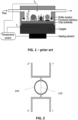
FIG. 1 schematically illustrates a known biosensor working on principles of the heat-transfer method (HTM). -
FIG. 2 schematically illustrates a device according to embodiments of the present invention where the heating element is confined with a seal. -
FIG. 3 schematically illustrates a cross-section of a heating element according to embodiments of the present invention. -
FIG. 4 schematically illustrates a device according to embodiments of the present invention. -
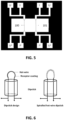
FIG. 5 schematically illustrates a top view of a printed circuit board (PCB) onto which a suspended heating elements according to embodiments of the present invention are provided. -
FIG. 6 schematically illustrates two devices having a dip-stick configuration, according to embodiments of the present invention. -
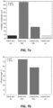
FIG. 7a and 7b illustrate experimental results for a measurement of the voltage (FIG. 7a ) and phase angle (FIG. 7b ) for a heating element with and without polystyrene polymer coating, in air or PBS, illustrating features of embodiments of the present invention. - Any reference signs in the claims shall not be construed as limiting the scope.
- In the different drawings, the same reference signs refer to the same or analogous elements.
- The present invention will be described with respect to particular embodiments and with reference to certain drawings but the invention is not limited thereto but only by the claims. The drawings described are only schematic and are non-limiting. In the drawings, the size of some of the elements may be exaggerated and not drawn on scale for illustrative purposes. The dimensions and the relative dimensions do not correspond to actual reductions to practice of the invention.
- Furthermore, the terms first, second and the like in the description and in the claims, are used for distinguishing between similar elements and not necessarily for describing a sequence, either temporally, spatially, in ranking or in any other manner. It is to be understood that the terms so used are interchangeable under appropriate circumstances and that the embodiments of the invention described herein are capable of operation in other sequences than described or illustrated herein.
- Moreover, the terms top, under and the like in the description and the claims are used for descriptive purposes and not necessarily for describing relative positions. It is to be understood that the terms so used are interchangeable under appropriate circumstances and that the embodiments of the invention described herein are capable of operation in other orientations than described or illustrated herein.
- It is to be noticed that the term "comprising", used in the claims, should not be interpreted as being restricted to the means listed thereafter; it does not exclude other elements or steps. It is thus to be interpreted as specifying the presence of the stated features, integers, steps or components as referred to, but does not preclude the presence or addition of one or more other features, integers, steps or components, or groups thereof. Thus, the scope of the expression "a device comprising means A and B" should not be limited to devices consisting only of components A and B. It means that with respect to the present invention, the only relevant components of the device are A and B.
- Reference throughout this specification to "one embodiment" or "an embodiment" means that a particular feature, structure or characteristic described in connection with the embodiment is included in at least one embodiment of the present invention. Thus, appearances of the phrases "in one embodiment" or "in an embodiment" in various places throughout this specification are not necessarily all referring to the same embodiment, but may. Furthermore, the particular features, structures or characteristics may be combined in any suitable manner, as would be apparent to one of ordinary skill in the art from this disclosure, in one or more embodiments.
- Similarly it should be appreciated that in the description of exemplary embodiments of the invention, various features of the invention are sometimes grouped together in a single embodiment, figure, or description thereof for the purpose of streamlining the disclosure and aiding in the understanding of one or more of the various inventive aspects. This method of disclosure, however, is not to be interpreted as reflecting an intention that the claimed invention requires more features than are expressly recited in each claim. Rather, as the following claims reflect, inventive aspects lie in less than all features of a single foregoing disclosed embodiment. Thus, the claims following the detailed description are hereby expressly incorporated into this detailed description, with each claim standing on its own as a separate embodiment of this invention.
- In the description provided herein, numerous specific details are set forth. However, it is understood that embodiments of the invention may be practiced without these specific details. In other instances, well-known methods, structures and techniques have not been shown in detail in order not to obscure an understanding of this description.
- Where in embodiments of the present invention reference is made to a plurality of binding sites at/to which target particles can bind, this may refer to binding sites to which the target particles can directly bind or indirectly bind e.g. using a third intermediate particle.
- In a first aspect, the present invention relates to a device suitable for the detection and/or characterization of target particles in a fluid. Characterization thereby may comprise identification of target particles, but also may include quantification of target particles. The target particles may be any particles of interest or particles that can act as a carrier and to which other particles of interest can be bound.
- According to the first aspect, the device comprises at least one heating element for heating and/or measuring a temperature. The heating element according to the present invention is a wire comprising a core comprising at least an electrically conducting portion and an electric isolating layer, said electric isolating layer provided at a surface of the core wherein said electric isolating layer electrically isolates the core from the sample. The heating element also comprises a plurality of binding sites at/to which target particles can bind. The device furthermore comprises a processing means or processor configured for measuring an electric output of the at least one heating element and/or a change in electric output of the least one heating element and/or a heating power of the at least one heating element. The processing means also is configured for deriving, based on the measured electric output of the at least one heating element or change in electric output of the at least one heating element or change in heating power, a characteristic of the target particles. The processing means may use a predetermined algorithm, a neural network or a look up table for deriving a characteristic of the target particles. The characteristic may be a presence, a quantity, a type, a modification or any other characteristic characterizing the target particles. Further standard and optional features and advantages will now further be described with reference to the drawings, embodiments of the present invention not being limited thereto.
-
FIG. 2 illustrates a device according to embodiments of the present invention, wherein the device comprises at least oneheating element 100 for heating using a heating power, wherein the heating element comprises a core and an electrical isolating layer (not shown). Theheating element 100 in this embodiment is a suspended wire, which may be referred to as a hot-wire as it is heated. The device illustrated inFIG. 2 may also comprise aseal 200,such as for example a flat seal or an O-ring seal. Furthermore the device comprises a processing means configured to measure an electric output of the least one heating element and/or its heating power and based thereon deriving a characteristic of the target bioparticles. The device ofFIG. 2 preferably works as follows: the heating element orwire 100 is heated up by for example by Joule heating to a defined temperature which may be calculated by measuring the electrical resistance of theheating element 100. The thermal resistance of an empty wire (with no particles present at the binding sites) is determined by the thickness of the electrical isolating layer. Therefore, the heat will dissipate through. When particles, present in a sample one wishes to evaluate, bind at the binding sites present on theheating element 100, the thermal resistance at the solid-liquid or solid-gas interface changes, e.g. increases as a result. Measuring a parameter linked to this change, e.g. increase in thermal resistance advantageously provides properties of the sample to be evaluated. In addition, embodiments of the present invention enable that the entire outer surface of the suspended heating element or wire may serve as a sensitive area, which in this specific embodiment is confined within aseal 200. In further embodiments measuring the resistance of the wire may be performed by using an at least two-point measuring geometry. In the embodiment illustrated inFIG. 2 a four-point geometry is used which advantageously may eliminate the influence of contact resistances and thermal voltages. In addition, the at least two-point geometry, e.g. a four-point geometry, eliminates thermal voltages, provided that the current is alternating with e.g. block pulses or sinus waves. The thermal energy of Joule heating is transferred to the liquid surrounding the wire. The transfer of thermal energy from thewire 100 to the surrounding fluid, e.g. a liquid or gas sample, depends on the physical and chemical properties of the wire-to-fluid interface, in analogy with the established HTM principle. -
FIG. 3 schematically illustrates a cross-section of a heating element orwire 100 according to embodiments of the present invention. The heating element comprises acore 10 and an electric isolating layer orskin 11 provided at a surface of the core wherein said electric isolating layer electrically isolates the core. The materials of the core may be chosen such that the electrical current flows through or around the core of the heating element or wire (e.g. by using a metal e.g. an aluminum or titanium core), which is electrically isolated from the surrounding sample or fluid, e.g. a liquid or gas, by a dense electrically isolating layer, e.g. oxide layer generated by for example oxidizing treatments such as annealing in air or anodization. The oxide layer may be surrounded by self-assemblinglinker molecules 30, preferably silane linkers. The linker molecules serve for tethering receptors to the surface of the wire, with single-strandedDNA 40, targetedDNA 41,DNA duplex 42 and aptamers as typical examples. Other core materials such as semiconductors or noble metals can be considered as well, in the latter case self-assembling layers, preferably thiol monolayers, may be used for simultaneously electrical insulation and linking of receptors. In further embodiments carbon nanotubes may be used as core material of the wire or heating element. In such embodiments the nanotubes may also be synthesized from a few other materials such as for example boron nitride. In other alternative embodiments the entire core may be an electrical conductor or an electrical isolating core with an electrically conducting coating may be used, like for example a glass fiber comprising a thin gold layer. - In preferred embodiments the heating element or wire may have a length in the order of millimeters and a diameter in the micrometer range (< 0.1 mm). The wire is configured such to sustain heating up to a predefined temperature (e.g. 37 °C) by passing a controlled current (I) through or surround it (e.g. Joule heating) while the resistance of the wire is measured by using at least a two-point geometry and preferably a four-point geometry. The temperature of the wire is related to its electrical resistance and preferably monitored as a function of time. The present invention is not limited to maintaining a constant temperature of the wire but may include the possibility to measure the temperature change of the wire over time, resulting from any kind of modulation of the current (I).
-
FIG. 4 illustrates a set-up of a device according to embodiments of the present invention. In this embodiment the device comprises aflow cell 400 in which the at least one heating element orwire 100 is suspended between at least two anchoring means. Theflow cell 400 comprising a channel, the channel comprising an inlet and outlet through which a fluid, e.g. liquid or gas, can flow in theflow cell 400. Suspending thewire 100 can be performed in various ways, like for example by using a magnetic field or by pulling the wire at its end in opposite directions. The wire may be anchored on a printed circuit board (PCB) 600 which is provided on a bottom substrate, preferably an optically transparent substrate likee.g. glass 500. On the PCB 600 athermocouple 210 may be provided in addition toelectrode contacts 220. The thermocouple serves as an independent temperature control inside theflow cell 400 and theelectrode 220 is used to check for potential electrical shortcuts between the core of the wire and the surrounding liquid. As a result, the thermocouple and electrode are optional and not needed for the proper functioning of the device according to the present invention. The device further comprises a top optically transparent layer,e.g. glass 501, resulting in that theflow cell 400 is sandwiched in-between the top 501 andbottom glass 500. Advantageously the top-and bottom glasses may be used for inspecting the flow cell optically with respect to air bubbles and visible changes at the wire. Although in embodiments an optically transparent top layer is provided, the present invention is not limited thereto. The device ofFIG. 4 may work as follows: a flow of a fluid is provided to the receptor-functionalizedwire 100 which is suspended, allowing target molecules and target particles to approach the wire from all possible sides. Advantageously, there is no laminar temperature profile necessary as in case of HTM and therefor the sensor also can operate under flow conditions. A variation of the geometry can be a wire that is not suspended freely but partly supported by an underlying solid surface. -
FIG. 5 illustrates a device according to embodiments of the present invention provided as a chip. More specificallyFIG. 5 illustrate a schematic top view of a PCB onto which at least one suspendedhot wire wire 100 is the active wire whereas theother wire 101 serves as a reference wire. Each end of thewires hot wires - As indicated above, embodiments of the present invention comprise a processing means or processor. Such a processor may be a dedicated processing means wherein the dedicated processing means is adapted for controlling the at least one heating element and for deriving the characteristic of the target particle. This processing device may be part of a personal computer, a smartphone or a tablet. It may be connected via a LAN, WAN or directly to the Internet. Other standard and optional features such as a memory, input channels, output channels, timers, etc. may be as well known by the person skilled in the art.
- According to some embodiments, the processor may be configured for performing 3ω measurements. A particular example, illustrating such a technique - embodiments not being limited thereto - is disclosed in "Thermal conductivity measurement from 30 to 750 K: the 3 ω method" by David G. Cahill in Rev. Sci. Instrum., Vol. 61, No. 2, February 1990 and in "3ω method for specific heat and thermal conductivity measurements" by L. Lu, W. Yi, and D. L. Zhang in Rev. SCi. Instrum., Vol. 72, No. 7, July 2001. By way of illustration one way to perform 3ω measurements will be described in some more detail here below. During 3-omega measurements a sinusoidal current with driving frequency omega is sent through the wire while voltage oscillations at three times this frequency are being measured. These oscillations are caused by changes in resistance of the heater, which occur at double the driving frequency. These changes, also known as Joule heating, are in turn a result of applying an ac power signal to an electrical resistor. A current source will supply the sinusoidal ac power signal at various driving frequencies while a lock-in amplifier will measure the voltage oscillations at three times the driving frequency. The amplitude of these oscillations is around three orders of magnitude lower than the voltage oscillations at the driving frequency. The precise value of the voltage and phase angle at the 3-omega frequency depends on the efficiency of heat transfer from the heated wire to the surrounding medium (mostly a liquid). This heat-transfer efficiency depends on the physical and chemical characteristics of the solid-to-liquid interface and is therefore sensitive to the binding of molecules to this interface and to changes of molecules tethered to said interface.
- In some embodiments, the wire design allows also to wind the wire in the shape of a loop or even a spiralled loop such as in an incandescent glow lamp. The spiralled design makes the active area larger and increases the resistance value, thus making the measurement of the wire resistance (indicating the wire temperature) more precise.
- In a particular embodiment, the device can be implemented as a dip-stick application, meaning that in principle no fluid container is required for the device itself, but that the device can be dipped into the fluid to be measured so as to identify, characterize or quantify target bioparticles of interest in the sample. A major advantage thus may exist in the fact that the sensing principle can be transferred to a simple dipstick design, making flow-through sensor cells and pumping systems obsolete. The dipstick design may especially be handy and can cope with samples with very low volumes. Two commercial biosensors, the blood-glucose test and the pregnancy test, work essentailly as dipsticks, although applications are not limited to these examples. By way of illustration, embodiments not being limited thereto, an example of a dipstick embodiment is shown in
FIG. 6 . - Using such dipstick embodiments, dipstick assays may be performed. Such assays may for example be performed using the following subsequent steps. In a first step, the dipstick device, or more particularly the wire portion thereof, is immersed in the liquid to be tested for a given time (e.g. 3 minutes), thus allowing bio-targets to be bound to the receptor coating. In a second step, the dipstick can be immersed in clean water or a physiological salt solution with known temperature such as 20°C. This means that the conditions in the immediate vicinity of the wire are well defined, relieving any ambiguities on the factors that may influence heat transfer from the wire to its immediate surroundings.
- In one aspect, the present invention also relates to a method for detecting and/or characterizing of target particles in a fluid. The method typically may comprise allowing a wire shaped heating element to interact with a fluid or more particularly the target bioparticles in the fluid. The wire shaped heating element that is used comprises a core comprising at least an electrically conducting portion, an electric isolating layer and a plurality of binding sides to which the target particles can bind. The method also comprises heating the wired shaped heating element. The method furthermore comprises measuring an electric output of the at least one heating element or a change thereof of the at least one wire shaped heating element and/or its heating power. Based on the measured electric output of the at least one heating element, the change of the electric output of the at least one heating element or the heating power used in the wire shaped heating element, a heat transfer analysis can be performed allowing to derive a characteristic of the target particles in the sample. In some embodiments, the method also may comprise, after allowing the heating element interact with the fluid, a step of contacting the heating element with clean water or a physiological salt solution with known temperature. According to some embodiments, the method thus implies using an electrically conducting wire that is covered with a receptor coating, allowing binding of analytically relevant particles to the receptor coating from a surrounding liquid. The liquid itself does not need to be electrically conducting. By sending an electrical current through the wire, Joule heating is caused and the thermal energy is transmitted to the surrounding liquid, thereby passing the receptor layer. The efficiency of the heat transfer depends on the presence or absence of target molecules captured by the receptor layer. The wire used may be used for all of the generation of the heat lux, as immobilization layer for the receptors and as a thermometer. By using, in some embodiments, the wire for these different functions, less components are required. In some embodiments, a 3-omega measurement technique is performed resulting in spreading of thermal waves into the liquid medium and allowing good detection of the heat transfer characteristics. Further steps may correspond with the functionality of elements or components as described for the first aspect.
- In one aspect, the present invention also relates to a heating element for heating and/or measuring a temperature used in a sensor. The heating element comprises a core,an electric isolating layer, said electric isolating layer provided at a surface of the core and wherein said electric isolating layer electrically isolates the core from the sample, and a plurality of binding sites at/to which target particles can bind. The heating element may be connectable to a processor so as to receive control signals and send measurement data to the processor, as described in the first aspect. Further features and advantages may be as described for the heating element in the device according to embodiments of the first aspect.
- While the invention has been illustrated and described in detail in the drawings and foregoing description, such illustration and description are to be considered illustrative or exemplary and not restrictive. The foregoing description details certain embodiments of the invention. It will be appreciated, however, that no matter how detailed the foregoing appears in text, the invention may be practiced in many ways. The invention is not limited to the disclosed embodiments.
- By way of illustration, embodiments of the present invention not being limited thereto, an example of a device according to a particular embodiment of the present invention will further be discussed below, to illustrate that the device can be used as bio- and/or chemical sensor based on a heat transfer principle. More particularly, the energy transfer from a heated wire to the ambient depends on the coatings around the wire. When a coating with bioreceptor properties is used, the efficiency of energy transfer depends on the binding of particles to the receptor coating. By monitoring the energy transfer, characterization of the binding particles can be performed.
- In the experiment, the exemplary device comprised a heating element being a CuNi 44 (WM50) heating wire, as obtained from Heermann (Germany), having a diameter of 100µm, with a resistivity of about 85Ω/m. The wire was wound into coils, such that there were about 30 windings, each corresponding with a 6.35 Ω resistance. The diameter of the coil was about 1mm. The experiments were performed using an alternating current, more particularly a sinusoidal signal, with a 90 mA amplitude at frequencies f between 10 Hz and 100Hz. The current source used was a Keithley 6221 current source. The voltage and phase angle was measured using a Stanford Research lock-in amplifier SR850. The voltage- and phase angles where measured using a 3ω measurement technique. The resistance measurements of the wire were performed in a 4-point geometry.
- Measurements were performed for a blank wire in air, a blank wire in a PBS buffer (with pH and salinity of blood plasma), a polymer coated wire in air and a polymer coated wire in a PBS buffer. The polymer coating used was a polystyrene (PS) coating with a thickness much smaller than 5µm. A single wire was used for the experiments.
- For a basic frequency f = 30 Hz, the 3 ω signal (90 Hz) was analysed. The results are shown in
FIG. 7a and 7b and a clear difference could be seen between both different media (air vs. PBS). Furthermore, in PBS solution also a clear difference could be seen between a blank and a polymer coated wire. - These measurements show that the efficiency of heat-transfer depends on the medium and the coating. It shows that the 3 ω signals allow to discriminate situations. Furthermore they show that both the voltage amplitude and the phase angle can be used as analytical parameters.
- Further by way of illustration, a number of exemplary fields of applications are discussed below, embodiments of the present invention not being limited thereto
- One application relates to the detection of hydrophobines in malt. Hydrophobines are induced by a fungal infection of barley and lead to an uncontrolled overflowing of the beer, rendering it unsaleable. Such hydrophobines cannot be removed from wort or beer by filtration or heat treatment. Therefore it is desirable to detect the hydrophobins in decoctions of barley and malt before commencing the brewing. The infected malt then can be rejected. For such applications, the receptors used in the device according to embodiments of the present invention may for example be molecular imprinted polymers (MIPs), antibodies or aptamer receptors. It is to be noted that the receptor layer in some embodiments may be regenerated for re-use. In some embodiments, the methods as described above may be applied.
- In one application, quantitative detection of biogenic amines such as histamine in food samples is performed based on devices and embodiments according to embodiments of the present invention.
- In yet another application, quantitative detection of antibiotics residues and residues of pesticides, fungicides, insecticides, herbicides, hormones and endocrine disrupters in the agricultural-, food- and water-safety sectors can be performed using devices and methods according to embodiments of the present invention. These embodiments provide cheap and portable sensing systems that may allow to provide quantitative information.
- In still another application, screening of substances for narcotic drugs such as cocaine can be performed using devices and methods according to embodiments of the present invention.
-
- [100] heating element
- [101] reference heating element
- [200] sealing means
- [10] core
- [11] electric isolating layer
- [30] silane linkers
- [40] probe DNA
- [41] target DNA
- [42] DNA duplex
- [210] thermocouple
- [500] bottom glass
- [501] top glass
- [220] electrode contacts
- [400] flow cell
- [600] printed circuit board (PCB)
Claims (14)
- A device suitable for the detection and/or characterization of target particles in a fluid, the device comprising:- at least one heating element (100) for heating and/or measuring a temperature, the heating element (100) being a wire comprising:o a core (10) comprising at least an electrically conducting portion,o an electric isolating layer (11), said electric isolating layer (11) provided at a surface of the core (10) and wherein said electric isolating layer (11) electrically isolates the core (10) from the sample, ando a plurality of binding sites (30) at/to which target particles (41) can bind;- a processing means configured for measuring an electric output of the at least one heating element (100) and/or a change in electric output of the at least one heating element (100) and/or its heating power and obtaining a measurement of the thermal resistance at an interface between the heating element and the fluid or change thereof and for deriving, based on the measurement of the thermal resistance of the at least one heating element or change thereof, a characteristic of the target particles.
- The device of claim 1, wherein the core (10) has a diameter of maximum 100µm, for example maximum 25 µm, for example maximum 10µm, for example in the nanometer range.
- The device of any of the previous claims, wherein the core (10) is completely made of an electrically conducting material, for example a material from a group consisting of metals and their alloys, precious metals, carbon nanotubes, semiconductors, boron nitride or a combination thereof.
- The device of any of claims 1 or 2, wherein a part of the core (10) is made of an electrically non-conducting material and wherein the at least an electrically conducting portion comprises a conductive coating on which the electric isolating layer (11) is provided, optionally wherein the conductive coating comprises a material from a group consisting of metals, metal alloys, precious metals, carbon nanotubes, semiconductors, boron nitride, or a combination thereof.
- The device of any of previous claims, wherein the electric isolating layer (11) is made of oxides, carbides, nitrides, polymers, thiols, silanes or thin polymer coatings, optionally wherein the plurality of binding sites at/to which target bioparticles can bind are provided directly or indirectly on the electric isolating layer.
- The device according to any of the previous claims, the device being a bio-sensing device further comprising a fluid compartment (400) for exposing the surface of the at least one heating element (100) to a fluid sample, the at least one heating element (100) being positioned in the fluid compartment (400).
- The device according to any of claims 1 to 5, wherein the device is a dipstick device adapted for dipping at least part of the at least one heating element into a fluid sample.
- The device according to any previous claims, wherein the at least one heating element (100) comprises a regularly shaped like e.g. cylindrical, square or triangular cross-section, or wherein the at least one heating element (100) comprises an irregularly shaped cross-section.
- The device according to any of previous claims, wherein the surface of the at least one heating element (100) is roughened.
- The device according to any of previous claims, wherein the at least one heating element (100) is suspended.
- The device according to any of the previous claims, wherein the at least one heating element (100) comprises a curved portion and/or a spiral shaped portion along the wire.
- The device according to any of the previous claims, wherein the plurality of binding sites (30) at/to which target particles can bind are one or more of single-stranded DNA, aptamers, antibodies, and molecularly imprinted polymers.
- The device according to any of the previous claims, wherein the processing means is adapted for performing a 3ω frequency analysis.
- A method for detecting and/or characterizing of target particles in a fluid, the method comprising:- allowing a wire shaped heating element (100) to interact with a fluid, the heating element (100) comprising a core (10) comprising at least an electrically conducting portion, an electric isolating layer (11) and a plurality of binding sites (930) to which the target particles can bind,- heating the wired shaped heating element (100),- measuring an electric output of the at least one heating element or a change thereof of the at least one wire shaped heating element (100) and/or its heating power,- obtaining a measurement of the thermal resistance at an interface between the heating element and the fluid or change thereof;- deriving, based on the measurement of the thermal resistance of the at least one heating element or change thereof, a characteristic of the target particles.
Applications Claiming Priority (2)
| Application Number | Priority Date | Filing Date | Title |
|---|---|---|---|
| GBGB1701291.5A GB201701291D0 (en) | 2017-01-26 | 2017-01-26 | Sensor |
| PCT/EP2018/052021 WO2018138299A1 (en) | 2017-01-26 | 2018-01-26 | Sensor |
Publications (3)
| Publication Number | Publication Date |
|---|---|
| EP3574313A1 EP3574313A1 (en) | 2019-12-04 |
| EP3574313C0 EP3574313C0 (en) | 2024-06-19 |
| EP3574313B1 true EP3574313B1 (en) | 2024-06-19 |
Family
ID=58462788
Family Applications (1)
| Application Number | Title | Priority Date | Filing Date |
|---|---|---|---|
| EP18702467.4A Active EP3574313B1 (en) | 2017-01-26 | 2018-01-26 | Sensor |
Country Status (4)
| Country | Link |
|---|---|
| US (1) | US11454627B2 (en) |
| EP (1) | EP3574313B1 (en) |
| GB (1) | GB201701291D0 (en) |
| WO (1) | WO2018138299A1 (en) |
Families Citing this family (5)
| Publication number | Priority date | Publication date | Assignee | Title |
|---|---|---|---|---|
| CN109771988B (en) * | 2019-01-25 | 2021-06-15 | 重庆工业职业技术学院 | Solid-phase microextraction method of diethyl phthalate based on molecular imprinting technology |
| GB2583927A (en) * | 2019-05-13 | 2020-11-18 | The Manchester Metropolitan Univ | A sensor device |
| CN111268814B (en) * | 2020-01-07 | 2022-05-24 | 昆明理工大学 | Anthracycline wastewater treatment method combining porous carbon nanosphere-based surface molecularly imprinted filter material and ultrafiltration molecularly imprinted membrane |
| CN111537561B (en) * | 2020-06-17 | 2021-11-23 | 清华大学 | Method and system for measuring interface thermal resistance |
| JP2024531971A (en) * | 2021-08-20 | 2024-09-03 | ユニバーシティ・オブ・シンシナティ | Aptamer sensor with temperature compensation |
Citations (1)
| Publication number | Priority date | Publication date | Assignee | Title |
|---|---|---|---|---|
| JP2009264904A (en) * | 2008-04-24 | 2009-11-12 | Sharp Corp | Sensor element using nano-structure, analyzing chip, analyzer, method for manufacturing sensor element and analysis method |
Family Cites Families (12)
| Publication number | Priority date | Publication date | Assignee | Title |
|---|---|---|---|---|
| US5424219A (en) * | 1991-10-25 | 1995-06-13 | Cytech Biomedical, Inc. | Method of performing assays for biomolecules and solid supports for use in such methods |
| US8722417B2 (en) * | 2003-04-28 | 2014-05-13 | Invoy Technologies, L.L.C. | Thermoelectric sensor for analytes in a fluid and related method |
| US9360509B2 (en) * | 2006-11-17 | 2016-06-07 | Trustees Of Boston College | Nanoscale sensors with nanoporous material |
| US8682408B2 (en) * | 2008-03-28 | 2014-03-25 | Dexcom, Inc. | Polymer membranes for continuous analyte sensors |
| US8283936B2 (en) | 2009-02-09 | 2012-10-09 | Board Of Regents, The University Of Texas System | Nano-scale biosensors |
| US10598627B2 (en) * | 2012-06-29 | 2020-03-24 | Dexcom, Inc. | Devices, systems, and methods to compensate for effects of temperature on implantable sensors |
| EP2772753B1 (en) | 2013-02-28 | 2018-10-03 | IMEC vzw | Heat-transfer resistance based analysis of bioparticles |
| US20150073515A1 (en) * | 2013-09-09 | 2015-03-12 | Medtronic Ardian Luxembourg S.a.r.I. | Neuromodulation Catheter Devices and Systems Having Energy Delivering Thermocouple Assemblies and Associated Methods |
| US20160178622A1 (en) * | 2014-12-19 | 2016-06-23 | Imec Vzw | Aptamer-Based Biosensing |
| FR3038982A1 (en) | 2015-07-16 | 2017-01-20 | Commissariat Energie Atomique | ANALYSIS DEVICE FOR ANALYZING A MIXTURE OF AT LEAST TWO GASES |
| US10139407B2 (en) * | 2016-04-11 | 2018-11-27 | Universiteit Maastricht | Methods for detecting bacteria using polymer materials |
| US20190204249A1 (en) * | 2016-04-11 | 2019-07-04 | Academisch Ziekenhuis Maastricht | Thermocouples comprising a polymer coating for detecting analytes and related methods |
-
2017
- 2017-01-26 GB GBGB1701291.5A patent/GB201701291D0/en not_active Ceased
-
2018
- 2018-01-26 WO PCT/EP2018/052021 patent/WO2018138299A1/en not_active Ceased
- 2018-01-26 US US16/480,188 patent/US11454627B2/en active Active
- 2018-01-26 EP EP18702467.4A patent/EP3574313B1/en active Active
Patent Citations (1)
| Publication number | Priority date | Publication date | Assignee | Title |
|---|---|---|---|---|
| JP2009264904A (en) * | 2008-04-24 | 2009-11-12 | Sharp Corp | Sensor element using nano-structure, analyzing chip, analyzer, method for manufacturing sensor element and analysis method |
Also Published As
| Publication number | Publication date |
|---|---|
| EP3574313A1 (en) | 2019-12-04 |
| EP3574313C0 (en) | 2024-06-19 |
| WO2018138299A1 (en) | 2018-08-02 |
| US20200284813A1 (en) | 2020-09-10 |
| GB201701291D0 (en) | 2017-03-15 |
| US11454627B2 (en) | 2022-09-27 |
Similar Documents
| Publication | Publication Date | Title |
|---|---|---|
| US11454627B2 (en) | Sensor | |
| US9448198B2 (en) | Microsensor with integrated temperature control | |
| Cui et al. | Rapid and sensitive detection of small biomolecule by capacitive sensing and low field AC electrothermal effect | |
| US8877518B2 (en) | Multiplexed nanoscale electrochemical sensors for multi-analyte detection | |
| CN102879453B (en) | Method and the device of the charged particle in handling liquids is come based on electrophoresis | |
| CN105980581A (en) | A capacitive sensor and method of use | |
| Kwak et al. | Localized dielectric loss heating in dielectrophoresis devices | |
| Antony et al. | Detection principles and development of microfluidic sensors in the last decade | |
| WO2009035732A2 (en) | Detection and quantification of biomarkers via a piezoelectric cantilever sensor | |
| EP2005148A1 (en) | Dielectric sensing method and system | |
| EP2649197A1 (en) | Heat-transfer resistance based analysis bioparticles | |
| JP2018505423A5 (en) | ||
| Cui et al. | Rapid capacitive detection of femtomolar levels of bisphenol A using an aptamer-modified disposable microelectrode array | |
| Khorshid et al. | The hot-wire concept: towards a one-element thermal biosensor platform | |
| Quoc et al. | High-frequency interdigitated array electrode-based capacitive biosensor for protein detection | |
| Santos et al. | Label-free detection of biomolecules in microfluidic systems using on-chip UV and impedimetric sensors | |
| JP2010513861A (en) | Wet and sensitive surface microelectronic devices | |
| Haring et al. | Piezoelectric cantilever biosensors for label-free, real-time detection of DNA and RNA | |
| KR100985475B1 (en) | Sensing Device and Sensing Method Using Dielectrophoretic Impedance | |
| US20050266396A1 (en) | Dielectric relaxation spectroscopy apparatus and methods of use | |
| Mansor et al. | A novel integrated dual microneedle-microfluidic impedance flow cytometry for cells detection in suspensions | |
| CN1996001A (en) | Biosensor for monitoring biological behavior of cell and biomolecule and sensing method therefor | |
| Tian et al. | Modeling of an Impedimetric Biosensor with Ultrasonic‐Assisted Cell Alignment for the Detection of Yeast | |
| US20040110230A1 (en) | Method for determining concentrations of analytes | |
| WO2020117446A1 (en) | Semiconductor-based biosensor and detection methods |
Legal Events
| Date | Code | Title | Description |
|---|---|---|---|
| STAA | Information on the status of an ep patent application or granted ep patent |
Free format text: STATUS: UNKNOWN |
|
| STAA | Information on the status of an ep patent application or granted ep patent |
Free format text: STATUS: THE INTERNATIONAL PUBLICATION HAS BEEN MADE |
|
| PUAI | Public reference made under article 153(3) epc to a published international application that has entered the european phase |
Free format text: ORIGINAL CODE: 0009012 |
|
| STAA | Information on the status of an ep patent application or granted ep patent |
Free format text: STATUS: REQUEST FOR EXAMINATION WAS MADE |
|
| 17P | Request for examination filed |
Effective date: 20190822 |
|
| AK | Designated contracting states |
Kind code of ref document: A1 Designated state(s): AL AT BE BG CH CY CZ DE DK EE ES FI FR GB GR HR HU IE IS IT LI LT LU LV MC MK MT NL NO PL PT RO RS SE SI SK SM TR |
|
| AX | Request for extension of the european patent |
Extension state: BA ME |
|
| DAV | Request for validation of the european patent (deleted) | ||
| DAX | Request for extension of the european patent (deleted) | ||
| STAA | Information on the status of an ep patent application or granted ep patent |
Free format text: STATUS: EXAMINATION IS IN PROGRESS |
|
| 17Q | First examination report despatched |
Effective date: 20220504 |
|
| GRAP | Despatch of communication of intention to grant a patent |
Free format text: ORIGINAL CODE: EPIDOSNIGR1 |
|
| STAA | Information on the status of an ep patent application or granted ep patent |
Free format text: STATUS: GRANT OF PATENT IS INTENDED |
|
| INTG | Intention to grant announced |
Effective date: 20240215 |
|
| GRAS | Grant fee paid |
Free format text: ORIGINAL CODE: EPIDOSNIGR3 |
|
| GRAA | (expected) grant |
Free format text: ORIGINAL CODE: 0009210 |
|
| STAA | Information on the status of an ep patent application or granted ep patent |
Free format text: STATUS: THE PATENT HAS BEEN GRANTED |
|
| AK | Designated contracting states |
Kind code of ref document: B1 Designated state(s): AL AT BE BG CH CY CZ DE DK EE ES FI FR GB GR HR HU IE IS IT LI LT LU LV MC MK MT NL NO PL PT RO RS SE SI SK SM TR |
|
| REG | Reference to a national code |
Ref country code: GB Ref legal event code: FG4D |
|
| REG | Reference to a national code |
Ref country code: CH Ref legal event code: EP |
|
| REG | Reference to a national code |
Ref country code: DE Ref legal event code: R096 Ref document number: 602018070746 Country of ref document: DE |
|
| U01 | Request for unitary effect filed |
Effective date: 20240712 |
|
| U07 | Unitary effect registered |
Designated state(s): AT BE BG DE DK EE FI FR IT LT LU LV MT NL PT SE SI Effective date: 20240718 |
|
| PG25 | Lapsed in a contracting state [announced via postgrant information from national office to epo] |
Ref country code: HR Free format text: LAPSE BECAUSE OF FAILURE TO SUBMIT A TRANSLATION OF THE DESCRIPTION OR TO PAY THE FEE WITHIN THE PRESCRIBED TIME-LIMIT Effective date: 20240619 |
|
| PG25 | Lapsed in a contracting state [announced via postgrant information from national office to epo] |
Ref country code: GR Free format text: LAPSE BECAUSE OF FAILURE TO SUBMIT A TRANSLATION OF THE DESCRIPTION OR TO PAY THE FEE WITHIN THE PRESCRIBED TIME-LIMIT Effective date: 20240920 |
|
| PG25 | Lapsed in a contracting state [announced via postgrant information from national office to epo] |
Ref country code: NO Free format text: LAPSE BECAUSE OF FAILURE TO SUBMIT A TRANSLATION OF THE DESCRIPTION OR TO PAY THE FEE WITHIN THE PRESCRIBED TIME-LIMIT Effective date: 20240919 Ref country code: HR Free format text: LAPSE BECAUSE OF FAILURE TO SUBMIT A TRANSLATION OF THE DESCRIPTION OR TO PAY THE FEE WITHIN THE PRESCRIBED TIME-LIMIT Effective date: 20240619 Ref country code: GR Free format text: LAPSE BECAUSE OF FAILURE TO SUBMIT A TRANSLATION OF THE DESCRIPTION OR TO PAY THE FEE WITHIN THE PRESCRIBED TIME-LIMIT Effective date: 20240920 Ref country code: RS Free format text: LAPSE BECAUSE OF FAILURE TO SUBMIT A TRANSLATION OF THE DESCRIPTION OR TO PAY THE FEE WITHIN THE PRESCRIBED TIME-LIMIT Effective date: 20240919 |
|
| PG25 | Lapsed in a contracting state [announced via postgrant information from national office to epo] |
Ref country code: PL Free format text: LAPSE BECAUSE OF FAILURE TO SUBMIT A TRANSLATION OF THE DESCRIPTION OR TO PAY THE FEE WITHIN THE PRESCRIBED TIME-LIMIT Effective date: 20240619 |
|
| PG25 | Lapsed in a contracting state [announced via postgrant information from national office to epo] |
Ref country code: IS Free format text: LAPSE BECAUSE OF FAILURE TO SUBMIT A TRANSLATION OF THE DESCRIPTION OR TO PAY THE FEE WITHIN THE PRESCRIBED TIME-LIMIT Effective date: 20241019 |
|
| PG25 | Lapsed in a contracting state [announced via postgrant information from national office to epo] |
Ref country code: CZ Free format text: LAPSE BECAUSE OF FAILURE TO SUBMIT A TRANSLATION OF THE DESCRIPTION OR TO PAY THE FEE WITHIN THE PRESCRIBED TIME-LIMIT Effective date: 20240619 |
|
| PG25 | Lapsed in a contracting state [announced via postgrant information from national office to epo] |
Ref country code: SK Free format text: LAPSE BECAUSE OF FAILURE TO SUBMIT A TRANSLATION OF THE DESCRIPTION OR TO PAY THE FEE WITHIN THE PRESCRIBED TIME-LIMIT Effective date: 20240619 Ref country code: RO Free format text: LAPSE BECAUSE OF FAILURE TO SUBMIT A TRANSLATION OF THE DESCRIPTION OR TO PAY THE FEE WITHIN THE PRESCRIBED TIME-LIMIT Effective date: 20240619 |
|
| PG25 | Lapsed in a contracting state [announced via postgrant information from national office to epo] |
Ref country code: SM Free format text: LAPSE BECAUSE OF FAILURE TO SUBMIT A TRANSLATION OF THE DESCRIPTION OR TO PAY THE FEE WITHIN THE PRESCRIBED TIME-LIMIT Effective date: 20240619 Ref country code: ES Free format text: LAPSE BECAUSE OF FAILURE TO SUBMIT A TRANSLATION OF THE DESCRIPTION OR TO PAY THE FEE WITHIN THE PRESCRIBED TIME-LIMIT Effective date: 20240619 |
|
| PG25 | Lapsed in a contracting state [announced via postgrant information from national office to epo] |
Ref country code: SM Free format text: LAPSE BECAUSE OF FAILURE TO SUBMIT A TRANSLATION OF THE DESCRIPTION OR TO PAY THE FEE WITHIN THE PRESCRIBED TIME-LIMIT Effective date: 20240619 Ref country code: SK Free format text: LAPSE BECAUSE OF FAILURE TO SUBMIT A TRANSLATION OF THE DESCRIPTION OR TO PAY THE FEE WITHIN THE PRESCRIBED TIME-LIMIT Effective date: 20240619 Ref country code: RO Free format text: LAPSE BECAUSE OF FAILURE TO SUBMIT A TRANSLATION OF THE DESCRIPTION OR TO PAY THE FEE WITHIN THE PRESCRIBED TIME-LIMIT Effective date: 20240619 Ref country code: PL Free format text: LAPSE BECAUSE OF FAILURE TO SUBMIT A TRANSLATION OF THE DESCRIPTION OR TO PAY THE FEE WITHIN THE PRESCRIBED TIME-LIMIT Effective date: 20240619 Ref country code: IS Free format text: LAPSE BECAUSE OF FAILURE TO SUBMIT A TRANSLATION OF THE DESCRIPTION OR TO PAY THE FEE WITHIN THE PRESCRIBED TIME-LIMIT Effective date: 20241019 Ref country code: ES Free format text: LAPSE BECAUSE OF FAILURE TO SUBMIT A TRANSLATION OF THE DESCRIPTION OR TO PAY THE FEE WITHIN THE PRESCRIBED TIME-LIMIT Effective date: 20240619 Ref country code: CZ Free format text: LAPSE BECAUSE OF FAILURE TO SUBMIT A TRANSLATION OF THE DESCRIPTION OR TO PAY THE FEE WITHIN THE PRESCRIBED TIME-LIMIT Effective date: 20240619 |
|
| U20 | Renewal fee for the european patent with unitary effect paid |
Year of fee payment: 8 Effective date: 20250128 |
|
| PLBE | No opposition filed within time limit |
Free format text: ORIGINAL CODE: 0009261 |
|
| STAA | Information on the status of an ep patent application or granted ep patent |
Free format text: STATUS: NO OPPOSITION FILED WITHIN TIME LIMIT |
|
| 26N | No opposition filed |
Effective date: 20250320 |
|
| REG | Reference to a national code |
Ref country code: CH Ref legal event code: PL |
|
| PG25 | Lapsed in a contracting state [announced via postgrant information from national office to epo] |
Ref country code: MC Free format text: LAPSE BECAUSE OF FAILURE TO SUBMIT A TRANSLATION OF THE DESCRIPTION OR TO PAY THE FEE WITHIN THE PRESCRIBED TIME-LIMIT Effective date: 20240619 |
|
| PG25 | Lapsed in a contracting state [announced via postgrant information from national office to epo] |
Ref country code: CH Free format text: LAPSE BECAUSE OF NON-PAYMENT OF DUE FEES Effective date: 20250131 |
|
| PG25 | Lapsed in a contracting state [announced via postgrant information from national office to epo] |
Ref country code: IE Free format text: LAPSE BECAUSE OF NON-PAYMENT OF DUE FEES Effective date: 20250126 |
|
| U20 | Renewal fee for the european patent with unitary effect paid |
Year of fee payment: 9 Effective date: 20260128 |
|
| PGFP | Annual fee paid to national office [announced via postgrant information from national office to epo] |
Ref country code: GB Payment date: 20260122 Year of fee payment: 9 |