EP3574222B1 - Flexural pivot - Google Patents
Flexural pivot Download PDFInfo
- Publication number
- EP3574222B1 EP3574222B1 EP17817433.0A EP17817433A EP3574222B1 EP 3574222 B1 EP3574222 B1 EP 3574222B1 EP 17817433 A EP17817433 A EP 17817433A EP 3574222 B1 EP3574222 B1 EP 3574222B1
- Authority
- EP
- European Patent Office
- Prior art keywords
- blade
- flexible
- flexure support
- flexure
- supports
- Prior art date
- Legal status (The legal status is an assumption and is not a legal conclusion. Google has not performed a legal analysis and makes no representation as to the accuracy of the status listed.)
- Active
Links
Images


Classifications
-
- F—MECHANICAL ENGINEERING; LIGHTING; HEATING; WEAPONS; BLASTING
- F16—ENGINEERING ELEMENTS AND UNITS; GENERAL MEASURES FOR PRODUCING AND MAINTAINING EFFECTIVE FUNCTIONING OF MACHINES OR INSTALLATIONS; THERMAL INSULATION IN GENERAL
- F16C—SHAFTS; FLEXIBLE SHAFTS; ELEMENTS OR CRANKSHAFT MECHANISMS; ROTARY BODIES OTHER THAN GEARING ELEMENTS; BEARINGS
- F16C11/00—Pivots; Pivotal connections
- F16C11/04—Pivotal connections
- F16C11/12—Pivotal connections incorporating flexible connections, e.g. leaf springs
-
- B—PERFORMING OPERATIONS; TRANSPORTING
- B23—MACHINE TOOLS; METAL-WORKING NOT OTHERWISE PROVIDED FOR
- B23H—WORKING OF METAL BY THE ACTION OF A HIGH CONCENTRATION OF ELECTRIC CURRENT ON A WORKPIECE USING AN ELECTRODE WHICH TAKES THE PLACE OF A TOOL; SUCH WORKING COMBINED WITH OTHER FORMS OF WORKING OF METAL
- B23H9/00—Machining specially adapted for treating particular metal objects or for obtaining special effects or results on metal objects
- B23H9/005—Machining elongated bodies, e.g. rods
-
- F—MECHANICAL ENGINEERING; LIGHTING; HEATING; WEAPONS; BLASTING
- F16—ENGINEERING ELEMENTS AND UNITS; GENERAL MEASURES FOR PRODUCING AND MAINTAINING EFFECTIVE FUNCTIONING OF MACHINES OR INSTALLATIONS; THERMAL INSULATION IN GENERAL
- F16D—COUPLINGS FOR TRANSMITTING ROTATION; CLUTCHES; BRAKES
- F16D3/00—Yielding couplings, i.e. with means permitting movement between the connected parts during the drive
- F16D3/005—Yielding couplings, i.e. with means permitting movement between the connected parts during the drive incorporating leaf springs, flexible parts of reduced thickness or the like acting as pivots
Definitions
- Flexural pivots are devices that permit mechanical members to pivot about a common axis relative to each other through a limited angle range. Because angular motion is accomplished through flexing of elastic flexural elements, rather than contact surface displacement, flexural pivots operate without friction and thus without a need for lubrication. Flexural pivots can therefore be a substitute for bearings in applications where friction and/or the need for lubrication are concerns.
- EP 0 840 023 A1 discloses a monolithic assembly comprising two rigid coplanar connecting elements located opposite each other and connected diagonally by a flexible strip.
- the flexible strip has at each end a transition zone of progressively variable section forming a junction between the strip and each connecting element.
- the strip has a reduced thickness zone between the two connecting elements.
- adjacent refers to the proximity of two structures or elements. Particularly, elements that are identified as being “adjacent” may be either abutting or connected. Such elements may also be near or close to each other without necessarily contacting each other. The exact degree of proximity may in some cases depend on the specific context.
- flexural pivots are commercially available for a variety of applications.
- Common problems with typical commercial off-the-shelf (COTS) flexural pivots are repeatable performance and reliability, particularly where high performance and durability are required for the application. This may be due to the difficulty in manufacturing flexural pivots in a commercially viable manner.
- COTS commercial off-the-shelf
- a flexural pivot can provide high performance and reliability and that is readily able to be manufactured.
- the flexural pivot can include a first flexure support member, a second flexure support member rotatably coupled to the first flexure support member for relative rotation about a first axis, and a third flexure support member rotatably coupled to the second flexure support member for relative rotation about a second axis.
- the flexural pivot can include a plurality of cross blade flexures rotatably coupling the flexure support members to one another.
- Each cross blade flexure can have first and second flexible blade units that have flexible blades arranged in a cross configuration.
- the flexible blade units can have blade supports disposed at opposite ends of the flexible blades to facilitate coupling the flexible blade units to the flexure support members.
- the flexible blade and the blade supports of each flexible blade unit can form a monolithic structure.
- a flexural pivot system can comprise a flexural pivot including a first flexure support member, a second flexure support member rotatably coupled to the first flexure support member for relative rotation about a first axis, and a third flexure support member rotatably coupled to the second flexure support member for relative rotation about a second axis.
- the flexural pivot can also include a plurality of cross blade flexures rotatably coupling the flexure support members to one another.
- Each cross blade flexure can have first and second flexible blade units that have flexible blades arranged in a cross configuration, the flexible blade units having blade supports disposed at opposite ends of the flexible blades to facilitate coupling the flexible blade units to the flexure support members.
- the flexible blade and the blade supports of each flexible blade unit can form a monolithic structure.
- the system can also include a first structure coupled to the first flexure support member, and a second structure coupled to the third flexure support member to facilitate relative rotation of the first and second structures about the first and second axes.
- a method for making a cross blade flexure can comprise obtaining a workpiece having a length.
- the method can also comprise forming a profile in the workpiece of a flexible blade and blade supports disposed at opposite ends of the flexible blade such that the profile extends along the length.
- the method can further comprise dividing the workpiece into portions along the length to form a plurality of flexible blade units, each having the same profile of flexible blades and blade supports in a monolithic structure.
- the method can comprise pairing two of the flexible blade units such that the flexible blades are arranged in a cross configuration to form a cross blade flexure. It is noted that no specific order is required in this method, though generally in one embodiment, these method steps can be carried out sequentially.
- the flexural pivot 100 can be coupled to and utilized with fast steering mirrors, which are commonly used in directed energy systems, long range laser communications systems, telescopes, or other precision optics applications, and therefore may be included in laboratory-based systems, airborne line of sight stabilization systems, satellites, etc.
- one external structure can be a mounting structure of a satellite, and the other external structure can be a mirror.
- the external structures can be coupled to the first and third flexure support members 110, 130 utilizing coupling interfaces such as openings or holes 111, 131, 132 (which may be threaded), a slot 133, a pin 112 (disposed in a hole 113), a stud, and other coupling interfaces.
- Two or more cross blade flexures can be utilized for a given axis to provide stability for the flexure support members.
- the second flexure support member 120 moves in only a single degree of freedom with respect to each of the first and third flexure support members 110, 130.
- the second flexure support member 120 may be referred to as a coupler due to its intermediate relationship with respect to the first and third flexure support members 110, 130, as well as its function coupling the two-axis rotational movement of the flexural pivot 100.
- Each cross blade flexure 140a-d can have two or more flexible blade units 141 that have flexible blades 142 arranged in a cross configuration.
- a flexible blade unit 141 is shown isolated in FIG. 2 .
- the flexible blade units 141 can have blade supports 143a, 143b disposed at opposite ends of the flexible blades 142 to facilitate coupling the flexible blade units 141 to the flexure support members 110, 120, 130.
- the flexible blades 142 extend perpendicularly from planar surfaces 144a, 144b of the respective blade supports 143a, 143b.
- the flexible blades 142 can have any suitable dimension, as the principles disclosed herein provide flexible blade units that are scalable to accommodate a wide range of sizes and applications.
- the flexible blades can have a length of 0.38 inches, a width of 0.15 inches, and a thickness of 0.033 inches.
- FIGS. 1A-1C For clarity, coupling features of the flexure support members 110, 120, 130, such as interface surfaces and holes, are identified on the second flexure support member 120 in FIGS. 1A-1C . These features are also shown in FIGS. 3-5 and identified with the same reference numbers associated with each individually illustrated flexure support member.
- the blade supports 143a, 143b can be welded to the flexure support members 110, 120, 130 and/or to adjacent blade supports of another flexible blade unit 141 to eliminate any slippage between adjacent components.
- the blade supports 143a, 143b and/or the flexure support members 110, 120, 130 can be welded at a seam between adjacent components (e.g., at a side seam).
- the flexible blades 142 of the flexible blade units 141 can be prevented from contacting adjacent components (e.g., another flexible blade unit 141 and/or a flexure support member 110, 120, 130 to which the flexible blade unit 141 is coupled) to facilitate smooth, unrestricted movement of the flexible blades 142 during operation.
- adjacent components e.g., another flexible blade unit 141 and/or a flexure support member 110, 120, 130 to which the flexible blade unit 141 is coupled
- the flexible blades 142 can be recessed relative to the interface surfaces 147 of the blade supports 143a, 143b to prevent the flexible blades 142 from contacting adjacent components.
- an outer surface 148 of the flexible blade 142 may not be coplanar or flush with the interface surfaces 147 of the blade supports 143a, 143b, and may be contained within an outer space envelope of the flexible blade unit 141 defined at least in part by the interface surfaces 147.
- the flexible blade units 141 can include travel stops 149a, 149b associated with each blade support 143a, 143b to mechanically limit a rotatable range of motion of the flexible blades 142.
- the opposing travel stops 149a, 149b of the blade supports 143a, 143b can be configured to contact one another at the rotational travel limits.
- the travel stops 149a, 149b can limit the range of motion to any suitable degree.
- the travel stops 149a, 149b will be configured to prevent excessive bending of the flexible blades 142 that may result in failure (e.g., yielding) of the blades.
- the travel stops 149a, 149b can have rounded contact tips 150a, 150b to provide more of a point-to-point contact between opposing travel stops.
- the travel stops 149a, 149b can be defined at least partially by the planar surfaces 144a, 144b and outer side surfaces 151a, 151b of the respective blade supports 143a, 143b, with the rounded contact tips 150a, 150b transitioning between them.
- the flexible blade units 141 can have any suitable outer shape or general profile, such as rectangular, circular, elliptical, etc.
- the general outer shape or profile of the flexible blade unit 141 shown in FIG. 2 is rectangular.
- the general outer shape or profile of a given flexible blade unit may be governed by the shape or design of the flexure support members 110, 120, 130, space constraints, etc.
- the principles disclosed herein can provide a flexure design that is repeatable and relatively simple to manufacture.
- multiple identical, monolithic flexible blade unit structures can be made simultaneously by forming a profile of the flexible blade unit 141 in a workpiece, which includes a profile of the flexible blade 142 and the blade supports 143a, 143b disposed at opposite ends of the flexible blade 142 and, optionally, the travel stops 149a, 149b.
- the profile of the flexible blade unit 141 can extend along a length of the workpiece.
- the length of the workpiece can be selected to at least equal a thickness of a final flexible blade unit 141 multiplied by the number of flexible blade units 141 to be obtained from the workpiece.
- all flexible blade units 141 for a given pivot flexure can be formed from the same workpiece and setup to ensure uniformity among the flexible blade units, which can provide predictable performance of the pivot flexure.
- all eight of the flexible blade units 141 can be formed from the same workpiece, thus ensuring all eight flexible blade units have the same profile and dimensional characteristics, varying only slightly due to the particular manufacturing technique utilized to form the profile in the workpiece.
- the profile can be formed in the workpiece in any suitable manner utilizing any suitable process or combination of processes.
- the profile may be formed in the workpiece by machining, extruding, casting, forging, etc.
- Example machining processes include electrical discharge machining (EDM), water jet cutting, milling, broaching, etc.
- EDM electrical discharge machining
- a manufacturing process may be selected based on the design objectives, tolerance requirements, cost, etc.
- a wire EDM process may provide precise machining that can meet tight tolerances and accurately control the flexure surfaces, which may be highly stressed during operation.
- the flexible blade units 141 can be made of any suitable material, such as titanium or steel.
- the workpiece can represent a stack of flexible blade units yet to be separated from one another into multiple individual flexible blade units. Accordingly, the workpiece can be divided into portions along the length to form multiple flexible blade units 141 from the workpiece that each have the same profile of flexible blades and blade supports in a monolithic structure.
- the workpiece can be divided into multiple flexible blade units 141 by any suitable process or technique, such as cutting, sawing, etc.
- a wire EDM process may be utilized to provide accurate control of the surfaces resulting from the dividing process, such as the interface surfaces 147. Final surfaces may be achieved by grinding, honing, polishing, etc. to a desired geometric and/or dimensional tolerance, and/or surface finish.
- the flexible blades 142 can optionally be recessed relative to the interface surfaces 147 of the blade supports 143a, 143b. Any suitable process can be utilized to recess the blades 142, such as grinding.
- one or more of the openings or holes 145, 146 to receive fasteners can be formed in the blade supports 143a, 143b at this stage.
- the openings or holes 145, 146 can be formed by any suitable process, such as drilling.
- one or more of the openings or holes 145, 146 can be formed prior to dividing the workpiece into multiple flexible blade units.
- two or more of the flexible blade units 141 can be arranged, such that the flexible blades 142 are arranged in a cross configuration to form the cross blade flexures 140a-d.
- the flexible blade units 141 can be stacked back to back to achieve the cross blade configuration.
- two of the flexible blade units 141 will be paired at a given location on the pivot flexure 100 to form the cross blade flexures 140a-d.
- the flexure support members 110, 120, 130 can be manufactured utilizing any suitable process or technique, such as those described above with respect to the flexible blade units 141 (e.g., milling, EDM, water jet machining, casting, forging, extruding, drilling, etc.).
Landscapes
- Engineering & Computer Science (AREA)
- General Engineering & Computer Science (AREA)
- Mechanical Engineering (AREA)
- Physics & Mathematics (AREA)
- Thermal Sciences (AREA)
- Pivots And Pivotal Connections (AREA)
- Turbine Rotor Nozzle Sealing (AREA)
- Electrical Discharge Machining, Electrochemical Machining, And Combined Machining (AREA)
Description
- Flexural pivots are devices that permit mechanical members to pivot about a common axis relative to each other through a limited angle range. Because angular motion is accomplished through flexing of elastic flexural elements, rather than contact surface displacement, flexural pivots operate without friction and thus without a need for lubrication. Flexural pivots can therefore be a substitute for bearings in applications where friction and/or the need for lubrication are concerns.
-
DE 10 2014 002182 A1 discloses biaxially deflectable monolithic solid-state joints in which the ends of two pairs of opposing bending cross springs are connected to each other via first webs and second webs. The spaced apart and interconnected first webs of a first pair of bending cross springs are a first connection element of the solid-state joint. The second webs of the first pair of bending cross springs are connected via third webs to the first webs of the second pair of bending cross springs. In addition, the spaced-apart and interconnected second webs of the second pair of bending cross-springs are the second connecting element of the solid-state joint. Thus, the solid-state joint is a gimbal arrangement with pairs of oppositely arranged bending cross springs. -
EP 0 840 023 A1 discloses a monolithic assembly comprising two rigid coplanar connecting elements located opposite each other and connected diagonally by a flexible strip. The flexible strip has at each end a transition zone of progressively variable section forming a junction between the strip and each connecting element. The strip has a reduced thickness zone between the two connecting elements. The manufacturing of a unit module consists in machining metal plates by electro-erosion and injecting plastic reinforced by high resistance fibres. - In one aspect, the present disclosure provides a flexural pivot, comprising: a first flexure support member; a second flexure support member rotatably coupled to the first flexure support member for relative rotation about a first axis; a third flexure support member rotatably coupled to the second flexure support member for relative rotation about a second axis; and a plurality of cross blade flexures rotatably coupling the flexure support members to one another, each cross blade flexure comprising first and second flexible blade units that have flexible blades arranged in a cross configuration, the flexible blade units comprising blade supports disposed at opposite ends of the flexible blades to facilitate coupling the flexible blade units to the flexure support members, wherein the flexible blade and the blade supports of each flexible blade unit form a monolithic structure, wherein the flexible blades extend perpendicularly from planar surfaces of the blade supports.
- In another aspect, the present disclosure provides a method for making a cross blade flexure, comprising: obtaining a workpiece having a length; forming a profile in the workpiece of a flexible blade and blade supports disposed at opposite ends of the flexible blade such that the profile extends along the length; dividing the workpiece into portions along the length to form a plurality of flexible blade units, each having the same profile of flexible blades and blade supports in a monolithic structure; and pairing two of the flexible blade units such that the flexible blades are arranged in a cross configuration to form a cross blade flexure.
- Features and advantages of the invention will be apparent from the detailed description which follows, taken in conjunction with the accompanying drawings, which together illustrate, by way of example, features of the invention; and, wherein:
-
FIG. 1A is a top perspective view of a flexural pivot in accordance with an example of the present disclosure. -
FIG. 1B is a bottom perspective view of the flexural pivot ofFIG. 1A . -
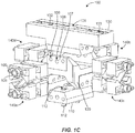
FIG. 1C is an exploded view of the flexural pivot ofFIG. 1A . -
FIG. 2 illustrates a flexible blade unit of the flexural pivot ofFIGS. 1A-1C . -
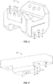
FIG. 3 illustrates a first flexure support member of the flexural pivot ofFIGS. 1A-1C . -
FIG. 4 illustrates a second flexure support member of the flexural pivot ofFIGS. 1A-1C . -
FIG. 5 illustrates a third flexure support member of the flexural pivot ofFIGS. 1A-1C . - Reference will now be made to the exemplary embodiments illustrated, and specific language will be used herein to describe the same. It will nevertheless be understood that no limitation of the scope of the invention is thereby intended.
- As used herein, the term "substantially" refers to the complete or nearly complete extent or degree of an action, characteristic, property, state, structure, item, or result. For example, an object that is "substantially" enclosed would mean that the object is either completely enclosed or nearly completely enclosed. The exact allowable degree of deviation from absolute completeness may in some cases depend on the specific context. However, generally speaking the nearness of completion will be so as to have the same overall result as if absolute and total completion were obtained. The use of "substantially" is equally applicable when used in a negative connotation to refer to the complete or near complete lack of an action, characteristic, property, state, structure, item, or result.
- As used herein, "adjacent" refers to the proximity of two structures or elements. Particularly, elements that are identified as being "adjacent" may be either abutting or connected. Such elements may also be near or close to each other without necessarily contacting each other. The exact degree of proximity may in some cases depend on the specific context.
- An initial overview of the inventive concepts is provided below and then specific examples are described in further detail later. This initial summary is intended to aid readers in understanding the examples more quickly, but is not intended to identify key features or essential features of the examples, nor is it intended to limit the scope of the claimed subject matter.
- A variety of flexural pivots are commercially available for a variety of applications. Common problems with typical commercial off-the-shelf (COTS) flexural pivots are repeatable performance and reliability, particularly where high performance and durability are required for the application. This may be due to the difficulty in manufacturing flexural pivots in a commercially viable manner. Thus, it is desirable to develop a flexural pivot design that provides high performance and reliability while being relatively simple and cost-effective to produce.
- Accordingly, a flexural pivot is disclosed that can provide high performance and reliability and that is readily able to be manufactured. The flexural pivot can include a first flexure support member, a second flexure support member rotatably coupled to the first flexure support member for relative rotation about a first axis, and a third flexure support member rotatably coupled to the second flexure support member for relative rotation about a second axis. In addition, the flexural pivot can include a plurality of cross blade flexures rotatably coupling the flexure support members to one another. Each cross blade flexure can have first and second flexible blade units that have flexible blades arranged in a cross configuration. The flexible blade units can have blade supports disposed at opposite ends of the flexible blades to facilitate coupling the flexible blade units to the flexure support members. The flexible blade and the blade supports of each flexible blade unit can form a monolithic structure.
- A flexural pivot system is also disclosed. The system can comprise a flexural pivot including a first flexure support member, a second flexure support member rotatably coupled to the first flexure support member for relative rotation about a first axis, and a third flexure support member rotatably coupled to the second flexure support member for relative rotation about a second axis. The flexural pivot can also include a plurality of cross blade flexures rotatably coupling the flexure support members to one another. Each cross blade flexure can have first and second flexible blade units that have flexible blades arranged in a cross configuration, the flexible blade units having blade supports disposed at opposite ends of the flexible blades to facilitate coupling the flexible blade units to the flexure support members. The flexible blade and the blade supports of each flexible blade unit can form a monolithic structure. The system can also include a first structure coupled to the first flexure support member, and a second structure coupled to the third flexure support member to facilitate relative rotation of the first and second structures about the first and second axes.
- in addition, a method for making a cross blade flexure is disclosed. The method can comprise obtaining a workpiece having a length. The method can also comprise forming a profile in the workpiece of a flexible blade and blade supports disposed at opposite ends of the flexible blade such that the profile extends along the length. The method can further comprise dividing the workpiece into portions along the length to form a plurality of flexible blade units, each having the same profile of flexible blades and blade supports in a monolithic structure. Additionally, the method can comprise pairing two of the flexible blade units such that the flexible blades are arranged in a cross configuration to form a cross blade flexure. It is noted that no specific order is required in this method, though generally in one embodiment, these method steps can be carried out sequentially.
- One embodiment of a
flexural pivot 100 is illustrated inFIGS. 1A-1C . Theflexural pivot 100 can comprise a firstflexure support member 110, a secondflexure support member 120 rotatably coupled to the firstflexure support member 110 for relative rotation about afirst axis 101, and a thirdflexure support member 130 rotatably coupled to the secondflexure support member 120 for relative rotation about asecond axis 102. Theaxes flexural pivot 100 can be coupled to external structures to facilitate relative rotation of the structures about theaxes flexural pivot 100 can be coupled to and utilized with fast steering mirrors, which are commonly used in directed energy systems, long range laser communications systems, telescopes, or other precision optics applications, and therefore may be included in laboratory-based systems, airborne line of sight stabilization systems, satellites, etc. Thus, one external structure can be a mounting structure of a satellite, and the other external structure can be a mirror. The external structures can be coupled to the first and thirdflexure support members holes slot 133, a pin 112 (disposed in a hole 113), a stud, and other coupling interfaces. - The
flexural pivot 100 can includecross blade flexures 140a-d rotatably coupling theflexure support members cross blade flexures 140a-b can rotatably couple the first and secondflexure support members cross blade flexures 140c-d can rotatably couple the second and thirdflexure support members flexure support members first axis 101, and the second and thirdflexure support members second axis 102, which can provide relative rotation of the first and thirdflexure support members flexure support member 120 moves in only a single degree of freedom with respect to each of the first and thirdflexure support members flexure support member 120 may be referred to as a coupler due to its intermediate relationship with respect to the first and thirdflexure support members flexural pivot 100. - Each
cross blade flexure 140a-d can have two or moreflexible blade units 141 that haveflexible blades 142 arranged in a cross configuration. Aflexible blade unit 141 is shown isolated inFIG. 2 . Theflexible blade units 141 can have blade supports 143a, 143b disposed at opposite ends of theflexible blades 142 to facilitate coupling theflexible blade units 141 to theflexure support members flexible blades 142 extend perpendicularly fromplanar surfaces flexible blades 142 can have any suitable dimension, as the principles disclosed herein provide flexible blade units that are scalable to accommodate a wide range of sizes and applications. In one example, the flexible blades can have a length of 0.38 inches, a width of 0.15 inches, and a thickness of 0.033 inches. - The
flexible blade units 141 can be coupled to theflexure support members openings holes flexure support members FIG. 1C ) that are planar. For clarity, coupling features of theflexure support members flexure support member 120 inFIGS. 1A-1C . These features are also shown inFIGS. 3-5 and identified with the same reference numbers associated with each individually illustrated flexure support member. - In one example, the
flexible blade units 141 can be assembled or coupled to theflexure support members bolts 105 extending through the openings orholes 145 in theflexible blade units 141 into openings orholes 108 in theflexure support members holes 146 in theflexible blade units 141 can be match drilled withholes 109 in theflexure support members pins 106 can then be inserted into the openings orholes holes flexure support members flexible blade unit 141 to eliminate any slippage between adjacent components. For example, the blade supports 143a, 143b and/or theflexure support members - In one aspect, the
flexible blades 142 of theflexible blade units 141 can be prevented from contacting adjacent components (e.g., anotherflexible blade unit 141 and/or aflexure support member flexible blade unit 141 is coupled) to facilitate smooth, unrestricted movement of theflexible blades 142 during operation. For example, theflexible blades 142 can be recessed relative to the interface surfaces 147 of the blade supports 143a, 143b to prevent theflexible blades 142 from contacting adjacent components. In other words, anouter surface 148 of theflexible blade 142 may not be coplanar or flush with the interface surfaces 147 of the blade supports 143a, 143b, and may be contained within an outer space envelope of theflexible blade unit 141 defined at least in part by the interface surfaces 147. - In one aspect, the
flexible blade units 141 can includetravel stops blade support flexible blades 142. The opposingtravel stops flexible blades 142 that may result in failure (e.g., yielding) of the blades. The travel stops 149a, 149b can have roundedcontact tips planar surfaces outer side surfaces rounded contact tips - The
flexible blade units 141 can have any suitable outer shape or general profile, such as rectangular, circular, elliptical, etc. The general outer shape or profile of theflexible blade unit 141 shown inFIG. 2 is rectangular. The general outer shape or profile of a given flexible blade unit may be governed by the shape or design of theflexure support members - The
flexible blade units 141 of thecross blade flexures 140a-d can be substantially identical, particularly with regard to perimeter shape (shown inFIG. 2 ), with the only differences being manufacturing deviations, such as minor variations in fastening features (e.g., theholes flexible blade units 141 can be monolithic or one-piece structures. For example, theflexible blade 142 and the blade supports 143a, 143b of eachflexible blade unit 141 can form a monolithic or one-piece structure created from a single workpiece or item of material. - In one aspect, the principles disclosed herein can provide a flexure design that is repeatable and relatively simple to manufacture. For example, multiple identical, monolithic flexible blade unit structures can be made simultaneously by forming a profile of the
flexible blade unit 141 in a workpiece, which includes a profile of theflexible blade 142 and the blade supports 143a, 143b disposed at opposite ends of theflexible blade 142 and, optionally, the travel stops 149a, 149b. The profile of theflexible blade unit 141 can extend along a length of the workpiece. The length of the workpiece can be selected to at least equal a thickness of a finalflexible blade unit 141 multiplied by the number offlexible blade units 141 to be obtained from the workpiece. In one aspect, allflexible blade units 141 for a given pivot flexure can be formed from the same workpiece and setup to ensure uniformity among the flexible blade units, which can provide predictable performance of the pivot flexure. In the case of thepivot flexure 100 ofFIGS. 1A-1C , all eight of theflexible blade units 141 can be formed from the same workpiece, thus ensuring all eight flexible blade units have the same profile and dimensional characteristics, varying only slightly due to the particular manufacturing technique utilized to form the profile in the workpiece. - The profile can be formed in the workpiece in any suitable manner utilizing any suitable process or combination of processes. For example, the profile may be formed in the workpiece by machining, extruding, casting, forging, etc. Example machining processes include electrical discharge machining (EDM), water jet cutting, milling, broaching, etc. A manufacturing process may be selected based on the design objectives, tolerance requirements, cost, etc. A wire EDM process may provide precise machining that can meet tight tolerances and accurately control the flexure surfaces, which may be highly stressed during operation. The
flexible blade units 141 can be made of any suitable material, such as titanium or steel. - Once the profile of the
flexible blade units 141 has been formed in the workpiece, the workpiece can represent a stack of flexible blade units yet to be separated from one another into multiple individual flexible blade units. Accordingly, the workpiece can be divided into portions along the length to form multipleflexible blade units 141 from the workpiece that each have the same profile of flexible blades and blade supports in a monolithic structure. The workpiece can be divided into multipleflexible blade units 141 by any suitable process or technique, such as cutting, sawing, etc. A wire EDM process may be utilized to provide accurate control of the surfaces resulting from the dividing process, such as the interface surfaces 147. Final surfaces may be achieved by grinding, honing, polishing, etc. to a desired geometric and/or dimensional tolerance, and/or surface finish. - With the
flexible blade units 141 separated from one another, theflexible blades 142 can optionally be recessed relative to the interface surfaces 147 of the blade supports 143a, 143b. Any suitable process can be utilized to recess theblades 142, such as grinding. In addition, one or more of the openings orholes holes holes - When the
flexible blade units 141 are completed sufficiently to begin assembly with theflexure support members flexible blade units 141 can be arranged, such that theflexible blades 142 are arranged in a cross configuration to form thecross blade flexures 140a-d. For example, theflexible blade units 141 can be stacked back to back to achieve the cross blade configuration. Typically, two of theflexible blade units 141 will be paired at a given location on thepivot flexure 100 to form thecross blade flexures 140a-d. Theflexure support members - It is to be understood that the examples set forth herein are not limited to the particular structures, process steps, or materials disclosed, but are extended to equivalents thereof as would be recognized by those ordinarily skilled in the relevant arts. It should also be understood that terminology employed herein is used for the purpose of describing particular examples only and is not intended to be limiting.
- Furthermore, the described features, structures, or characteristics may be combined in any suitable manner in one or more examples. In the description, numerous specific details are provided, such as examples of lengths, widths, shapes, etc., to provide a thorough understanding of the technology being described. One skilled in the relevant art will recognize, however, that the invention can be practiced without one or more of the specific details, or with other methods, components, materials, etc. In other instances, well-known structures, materials, or operations are not shown or described in detail to avoid obscuring aspects of the invention.
- While the foregoing examples are illustrative of the principles of the invention in one or more particular applications, it will be apparent to those of ordinary skill in the art that numerous modifications in form, usage and details of implementation can be made without the exercise of inventive faculty, and without departing from the principles and concepts described herein. Accordingly, it is not intended that the invention be limited, except as by the claims set forth below.
Claims (15)
- A flexural pivot (100), comprising:a first flexure support member (110);a second flexure support member (120) rotatably coupled to the first flexure support member for relative rotation about a first axis (101);a third flexure support member (130) rotatably coupled to the second flexure support member for relative rotation about a second axis (102); anda plurality of cross blade flexures (140a-d) rotatably coupling the flexure support members to one another, each cross blade flexure comprising first and second flexible blade units (141) that have flexible blades (142) arranged in a cross configuration, the flexible blade units comprising blade supports (143a, 143b) disposed at opposite ends of the flexible blades to facilitate coupling the flexible blade units to the flexure support members, wherein the flexible blade and the blade supports of each flexible blade unit form a monolithic structure, wherein the flexible blades extend perpendicularly from planar surfaces (144a, 144b) of the blade supports.
- The flexural pivot of claim 1, wherein at least one of the flexible blade units further comprises travel stops (149a, 149b) associated with the blade supports to mechanically limit a rotatable range of motion.
- The flexural pivot of claim 1, wherein the flexible blade units are coupled to the flexure support members with fasteners, and the blade supports comprise openings (145, 146) to receive the fasteners.
- The flexural pivot of claim 1, wherein the blade supports are welded to the flexure support members; or
wherein adjacent blade supports of the first and second flexible blade units are welded to one another. - The flexural pivot of claim 1, wherein the first and second flexible blade units of at least one of the cross blade flexures are substantially identical.
- The flexural pivot of claim 1, wherein interface surfaces (147, 107) of the blade supports and the flexure support members are planar.
- The flexural pivot of claim 1, wherein the flexible blades are recessed relative to interface surfaces of the blade supports to prevent the flexible blades from contacting adjacent components.
- The flexural pivot of claim 1, wherein the flexible blade units are made of titanium or steel.
- A flexural pivot system, comprising:a flexural pivot according to any one of claims 1 to 8;a first structure coupled to the first flexure support member; anda second structure coupled to the third flexure support member to facilitate relative rotation of the first and second structures about the first and second axes.
- A method for making a cross blade flexure (140a-d), comprising:obtaining a workpiece having a length;forming a profile in the workpiece of a flexible blade (142) and blade supports (143a, 143b) disposed at opposite ends of the flexible blade such that the profile extends along the length;dividing the workpiece into portions along the length to form a plurality of flexible blade units (141), each having the same profile of flexible blades and blade supports in a monolithic structure; andpairing two of the flexible blade units such that the flexible blades are arranged in a cross configuration to form a cross blade flexure (140a-d).
- The method of claim 10, wherein forming a profile in the workpiece comprises machining the workpiece; and
preferably, wherein machining the workpiece comprises electrical discharge machining 'EDM'. - The method of claim 10, further comprising forming a profile in the workpiece of travel stops (149a, 149b) associated with the blade supports.
- The method of claim 10, further comprising recessing the flexible blades relative to interface surfaces (147) of the blade supports.
- The method of claim 10, wherein the flexible blades extend perpendicularly from planar surfaces (144a, 144b) of the blade supports.
- The method of claim 10, further comprising forming openings (145, 146) in the blade supports to receive fasteners.
Applications Claiming Priority (2)
| Application Number | Priority Date | Filing Date | Title |
|---|---|---|---|
| US15/414,201 US10443649B2 (en) | 2017-01-24 | 2017-01-24 | Flexural pivot |
| PCT/US2017/062884 WO2018140128A1 (en) | 2017-01-24 | 2017-11-21 | Flexural pivot |
Publications (2)
| Publication Number | Publication Date |
|---|---|
| EP3574222A1 EP3574222A1 (en) | 2019-12-04 |
| EP3574222B1 true EP3574222B1 (en) | 2020-12-23 |
Family
ID=60703059
Family Applications (1)
| Application Number | Title | Priority Date | Filing Date |
|---|---|---|---|
| EP17817433.0A Active EP3574222B1 (en) | 2017-01-24 | 2017-11-21 | Flexural pivot |
Country Status (5)
| Country | Link |
|---|---|
| US (1) | US10443649B2 (en) |
| EP (1) | EP3574222B1 (en) |
| JP (1) | JP6761131B2 (en) |
| IL (1) | IL267763B (en) |
| WO (1) | WO2018140128A1 (en) |
Families Citing this family (9)
| Publication number | Priority date | Publication date | Assignee | Title |
|---|---|---|---|---|
| US10914339B2 (en) * | 2018-09-25 | 2021-02-09 | Ball Aerospace & Technologies Corp. | Flexural pivot assembly with shaped blade sections |
| US10771710B2 (en) | 2018-10-22 | 2020-09-08 | Raytheon Company | Shutter assembly for managing light relative to a photosensitive device |
| US11473616B2 (en) | 2018-10-22 | 2022-10-18 | Raytheon Company | Flexure device |
| US11326734B2 (en) | 2019-10-03 | 2022-05-10 | Raytheon Company | Monolithic gimbal for a fast steering mirror |
| US11566662B2 (en) | 2019-10-25 | 2023-01-31 | Raytheon Company | Multi-axis flexure |
| US12130423B1 (en) | 2020-08-12 | 2024-10-29 | Bae Systems Space & Mission Systems Inc. | Two degree-of freedom reactionless pointing and scanning system |
| US11822146B2 (en) * | 2021-02-18 | 2023-11-21 | Raytheon Company | Fast steering monolithic dual axis mirror and method for manufacturing |
| US12320466B2 (en) | 2021-03-10 | 2025-06-03 | Bae Systems Space & Mission Systems Inc. | Systems and methods for limiting rotation of a supported object |
| US12313905B1 (en) | 2022-03-15 | 2025-05-27 | Bae Systems Space & Mission Systems Inc. | Monolithic two-axis flexure with center hole feature |
Family Cites Families (32)
| Publication number | Priority date | Publication date | Assignee | Title |
|---|---|---|---|---|
| US2793028A (en) * | 1954-09-10 | 1957-05-21 | Hughes Aircraft Co | Cross-spring flexure pivot |
| US2931092A (en) * | 1957-01-14 | 1960-04-05 | Paul E Humphrey | Cross spring flexure pivot and process of making the same |
| US3252696A (en) * | 1963-10-21 | 1966-05-24 | Bendix Corp | Flexural pivot device |
| FR2198578A5 (en) * | 1972-09-05 | 1974-03-29 | Bendix Corp | |
| US3844022A (en) * | 1972-09-05 | 1974-10-29 | Bendix Corp | Method of making a universal flexural assembly |
| US3813089A (en) | 1972-09-08 | 1974-05-28 | Bendix Corp | Eccentric flexural pivot |
| DE2257903C3 (en) * | 1972-11-25 | 1978-03-02 | Kupplungstechnik Gmbh, 4440 Rheine | Ring-shaped, elastic element for connecting two coupling flanges |
| DE3213720C2 (en) * | 1982-04-14 | 1985-09-05 | Bodenseewerk Gerätetechnik GmbH, 7770 Überlingen | Dynamically coordinated cardan suspension with two degrees of freedom |
| US4497465A (en) * | 1983-03-31 | 1985-02-05 | Storage Technology Partners Ii | Pivotal mechanism upon which tracking mirrors and the like used in optical systems may be mounted |
| US4694703A (en) * | 1984-06-28 | 1987-09-22 | Lear Siegler, Inc. | Circumferentially oriented flexure suspension |
| IL73030A (en) * | 1984-09-19 | 1989-07-31 | Yaacov Kaufman | Joint and method utilising its assembly |
| US4812072A (en) * | 1988-03-11 | 1989-03-14 | Santa Barbara Research Center | Torsion structural pivot |
| US4802784A (en) | 1988-03-11 | 1989-02-07 | Santa Barbara Research Center | Bi-flex pivot |
| US5061107A (en) * | 1989-12-22 | 1991-10-29 | Santa Barbara Research Center | Torflex pivot |
| US4997123A (en) | 1990-05-31 | 1991-03-05 | Lucas Aerospace Power Transmission Corp. | Multi-piece flexural pivot |
| US5335418A (en) * | 1992-02-10 | 1994-08-09 | Snap-On Tools Corporation | Pivotal hand tool with flexural pivot joint and method of assembling same |
| US5265853A (en) * | 1992-03-12 | 1993-11-30 | Thomas Szirtes | Extended angular range flexural pivot |
| US5498095A (en) * | 1994-05-19 | 1996-03-12 | Snap-On Incorporated | Press fitted flexural pivot joint |
| US5620169A (en) * | 1994-11-02 | 1997-04-15 | Ball Corporation | Rotary mount integral flexural pivot with blades which are integrally interconnected at the blade intersection |
| FR2754577B1 (en) | 1996-10-11 | 1998-12-11 | Suisse Electronique Microtech | PLANAR FLEXIBLE PIVOT WITH MONOLITHIC UNIT MODULES |
| US6146044A (en) | 1997-09-02 | 2000-11-14 | California Institute Of Technology | Rotary flexure |
| FR2797923B1 (en) * | 1999-08-31 | 2001-10-26 | Centre Nat Etd Spatiales | FLEXIBLE BLADE PIVOT |
| US6479782B1 (en) * | 2000-08-09 | 2002-11-12 | Goodrich Corporation | Fabrication of a brazeless cross-blade flexure block |
| US6896384B2 (en) * | 2003-06-17 | 2005-05-24 | Alcon Refractivehorizons, Inc. | Laser beam translation system and method |
| US7832880B2 (en) * | 2006-08-08 | 2010-11-16 | Selex Galileo Ltd | Mirror mount having plural flexure elements |
| US8400721B2 (en) | 2007-03-08 | 2013-03-19 | Redstone Aerospace Corporation | Leaf-cartwheel flexure, and mounting systems and methods utilizing same |
| US8708593B2 (en) * | 2010-02-04 | 2014-04-29 | Eric M. Stratton | Cross-flexural pivot |
| US8556533B2 (en) * | 2011-11-21 | 2013-10-15 | Raytheon Company | Multi-stage flexural pivot |
| US9212691B2 (en) | 2012-05-16 | 2015-12-15 | C-Flex Bearing Co., Inc. | Cross blade flexure pivot and methods of use thereof |
| WO2014015156A2 (en) * | 2012-07-20 | 2014-01-23 | Boston Scientific Scimed, Inc. | Elongate medical device with articulating portion |
| EP2875915B1 (en) * | 2013-11-22 | 2019-05-22 | Koninklijke Philips N.V. | Linkage unit and hair cutting appliance |
| DE102014002182B4 (en) | 2014-02-15 | 2016-04-07 | Laservorm Gmbh | Biaxial deflectable monolithic solid-body joint |
-
2017
- 2017-01-24 US US15/414,201 patent/US10443649B2/en active Active
- 2017-11-21 WO PCT/US2017/062884 patent/WO2018140128A1/en not_active Ceased
- 2017-11-21 JP JP2019538650A patent/JP6761131B2/en active Active
- 2017-11-21 EP EP17817433.0A patent/EP3574222B1/en active Active
-
2019
- 2019-07-01 IL IL267763A patent/IL267763B/en active IP Right Grant
Non-Patent Citations (1)
| Title |
|---|
| None * |
Also Published As
| Publication number | Publication date |
|---|---|
| US20180209475A1 (en) | 2018-07-26 |
| JP2020506340A (en) | 2020-02-27 |
| IL267763A (en) | 2019-09-26 |
| EP3574222A1 (en) | 2019-12-04 |
| US10443649B2 (en) | 2019-10-15 |
| WO2018140128A1 (en) | 2018-08-02 |
| IL267763B (en) | 2020-10-29 |
| JP6761131B2 (en) | 2020-09-23 |
Similar Documents
| Publication | Publication Date | Title |
|---|---|---|
| US10443649B2 (en) | Flexural pivot | |
| EP3589853B1 (en) | Flexural pivot | |
| EP3904708B1 (en) | Flexural pivot manufacturing system | |
| EP3870868B1 (en) | Flexure device | |
| EP2682550B1 (en) | Flexible composite hinge | |
| KR102763342B1 (en) | Blade flexure assembly with replaceable elements | |
| CN111102446A (en) | Pivot flexure with uniform moment stiffness | |
| US11441598B2 (en) | Dual-axis flexure gimbal device | |
| US9920874B2 (en) | Linkage rod including limited-displacement flexible mechanism | |
| CN114483781B (en) | Manufacturing method of crossed reed flexible bearing | |
| US11566662B2 (en) | Multi-axis flexure | |
| CN212407307U (en) | Linkage device and double-shaft linkage module | |
| CN212803919U (en) | Linkage device and double-shaft linkage module | |
| CN207005008U (en) | A kind of deflecting beam for the plate that is connected and the assembling cabinet with the deflecting beam | |
| CN113586591A (en) | Linkage device and double-shaft linkage module | |
| US6688070B2 (en) | Structural member and methods of use | |
| CN116994487A (en) | Composite beam and teaching aid thereof |
Legal Events
| Date | Code | Title | Description |
|---|---|---|---|
| STAA | Information on the status of an ep patent application or granted ep patent |
Free format text: STATUS: UNKNOWN |
|
| STAA | Information on the status of an ep patent application or granted ep patent |
Free format text: STATUS: THE INTERNATIONAL PUBLICATION HAS BEEN MADE |
|
| PUAI | Public reference made under article 153(3) epc to a published international application that has entered the european phase |
Free format text: ORIGINAL CODE: 0009012 |
|
| STAA | Information on the status of an ep patent application or granted ep patent |
Free format text: STATUS: REQUEST FOR EXAMINATION WAS MADE |
|
| 17P | Request for examination filed |
Effective date: 20190823 |
|
| AK | Designated contracting states |
Kind code of ref document: A1 Designated state(s): AL AT BE BG CH CY CZ DE DK EE ES FI FR GB GR HR HU IE IS IT LI LT LU LV MC MK MT NL NO PL PT RO RS SE SI SK SM TR |
|
| AX | Request for extension of the european patent |
Extension state: BA ME |
|
| DAV | Request for validation of the european patent (deleted) | ||
| DAX | Request for extension of the european patent (deleted) | ||
| GRAP | Despatch of communication of intention to grant a patent |
Free format text: ORIGINAL CODE: EPIDOSNIGR1 |
|
| STAA | Information on the status of an ep patent application or granted ep patent |
Free format text: STATUS: GRANT OF PATENT IS INTENDED |
|
| INTG | Intention to grant announced |
Effective date: 20200625 |
|
| GRAS | Grant fee paid |
Free format text: ORIGINAL CODE: EPIDOSNIGR3 |
|
| GRAA | (expected) grant |
Free format text: ORIGINAL CODE: 0009210 |
|
| STAA | Information on the status of an ep patent application or granted ep patent |
Free format text: STATUS: THE PATENT HAS BEEN GRANTED |
|
| AK | Designated contracting states |
Kind code of ref document: B1 Designated state(s): AL AT BE BG CH CY CZ DE DK EE ES FI FR GB GR HR HU IE IS IT LI LT LU LV MC MK MT NL NO PL PT RO RS SE SI SK SM TR |
|
| REG | Reference to a national code |
Ref country code: GB Ref legal event code: FG4D |
|
| REG | Reference to a national code |
Ref country code: DE Ref legal event code: R096 Ref document number: 602017030200 Country of ref document: DE |
|
| REG | Reference to a national code |
Ref country code: AT Ref legal event code: REF Ref document number: 1348009 Country of ref document: AT Kind code of ref document: T Effective date: 20210115 |
|
| REG | Reference to a national code |
Ref country code: IE Ref legal event code: FG4D |
|
| PG25 | Lapsed in a contracting state [announced via postgrant information from national office to epo] |
Ref country code: GR Free format text: LAPSE BECAUSE OF FAILURE TO SUBMIT A TRANSLATION OF THE DESCRIPTION OR TO PAY THE FEE WITHIN THE PRESCRIBED TIME-LIMIT Effective date: 20210324 Ref country code: NO Free format text: LAPSE BECAUSE OF FAILURE TO SUBMIT A TRANSLATION OF THE DESCRIPTION OR TO PAY THE FEE WITHIN THE PRESCRIBED TIME-LIMIT Effective date: 20210323 Ref country code: RS Free format text: LAPSE BECAUSE OF FAILURE TO SUBMIT A TRANSLATION OF THE DESCRIPTION OR TO PAY THE FEE WITHIN THE PRESCRIBED TIME-LIMIT Effective date: 20201223 Ref country code: FI Free format text: LAPSE BECAUSE OF FAILURE TO SUBMIT A TRANSLATION OF THE DESCRIPTION OR TO PAY THE FEE WITHIN THE PRESCRIBED TIME-LIMIT Effective date: 20201223 |
|
| REG | Reference to a national code |
Ref country code: AT Ref legal event code: MK05 Ref document number: 1348009 Country of ref document: AT Kind code of ref document: T Effective date: 20201223 |
|
| REG | Reference to a national code |
Ref country code: NL Ref legal event code: MP Effective date: 20201223 |
|
| PG25 | Lapsed in a contracting state [announced via postgrant information from national office to epo] |
Ref country code: BG Free format text: LAPSE BECAUSE OF FAILURE TO SUBMIT A TRANSLATION OF THE DESCRIPTION OR TO PAY THE FEE WITHIN THE PRESCRIBED TIME-LIMIT Effective date: 20210323 Ref country code: SE Free format text: LAPSE BECAUSE OF FAILURE TO SUBMIT A TRANSLATION OF THE DESCRIPTION OR TO PAY THE FEE WITHIN THE PRESCRIBED TIME-LIMIT Effective date: 20201223 Ref country code: LV Free format text: LAPSE BECAUSE OF FAILURE TO SUBMIT A TRANSLATION OF THE DESCRIPTION OR TO PAY THE FEE WITHIN THE PRESCRIBED TIME-LIMIT Effective date: 20201223 |
|
| PG25 | Lapsed in a contracting state [announced via postgrant information from national office to epo] |
Ref country code: HR Free format text: LAPSE BECAUSE OF FAILURE TO SUBMIT A TRANSLATION OF THE DESCRIPTION OR TO PAY THE FEE WITHIN THE PRESCRIBED TIME-LIMIT Effective date: 20201223 Ref country code: NL Free format text: LAPSE BECAUSE OF FAILURE TO SUBMIT A TRANSLATION OF THE DESCRIPTION OR TO PAY THE FEE WITHIN THE PRESCRIBED TIME-LIMIT Effective date: 20201223 |
|
| REG | Reference to a national code |
Ref country code: LT Ref legal event code: MG9D |
|
| PG25 | Lapsed in a contracting state [announced via postgrant information from national office to epo] |
Ref country code: LT Free format text: LAPSE BECAUSE OF FAILURE TO SUBMIT A TRANSLATION OF THE DESCRIPTION OR TO PAY THE FEE WITHIN THE PRESCRIBED TIME-LIMIT Effective date: 20201223 Ref country code: CZ Free format text: LAPSE BECAUSE OF FAILURE TO SUBMIT A TRANSLATION OF THE DESCRIPTION OR TO PAY THE FEE WITHIN THE PRESCRIBED TIME-LIMIT Effective date: 20201223 Ref country code: EE Free format text: LAPSE BECAUSE OF FAILURE TO SUBMIT A TRANSLATION OF THE DESCRIPTION OR TO PAY THE FEE WITHIN THE PRESCRIBED TIME-LIMIT Effective date: 20201223 Ref country code: SM Free format text: LAPSE BECAUSE OF FAILURE TO SUBMIT A TRANSLATION OF THE DESCRIPTION OR TO PAY THE FEE WITHIN THE PRESCRIBED TIME-LIMIT Effective date: 20201223 Ref country code: PT Free format text: LAPSE BECAUSE OF FAILURE TO SUBMIT A TRANSLATION OF THE DESCRIPTION OR TO PAY THE FEE WITHIN THE PRESCRIBED TIME-LIMIT Effective date: 20210423 Ref country code: SK Free format text: LAPSE BECAUSE OF FAILURE TO SUBMIT A TRANSLATION OF THE DESCRIPTION OR TO PAY THE FEE WITHIN THE PRESCRIBED TIME-LIMIT Effective date: 20201223 Ref country code: RO Free format text: LAPSE BECAUSE OF FAILURE TO SUBMIT A TRANSLATION OF THE DESCRIPTION OR TO PAY THE FEE WITHIN THE PRESCRIBED TIME-LIMIT Effective date: 20201223 |
|
| PG25 | Lapsed in a contracting state [announced via postgrant information from national office to epo] |
Ref country code: PL Free format text: LAPSE BECAUSE OF FAILURE TO SUBMIT A TRANSLATION OF THE DESCRIPTION OR TO PAY THE FEE WITHIN THE PRESCRIBED TIME-LIMIT Effective date: 20201223 Ref country code: AT Free format text: LAPSE BECAUSE OF FAILURE TO SUBMIT A TRANSLATION OF THE DESCRIPTION OR TO PAY THE FEE WITHIN THE PRESCRIBED TIME-LIMIT Effective date: 20201223 |
|
| REG | Reference to a national code |
Ref country code: DE Ref legal event code: R097 Ref document number: 602017030200 Country of ref document: DE |
|
| PG25 | Lapsed in a contracting state [announced via postgrant information from national office to epo] |
Ref country code: IS Free format text: LAPSE BECAUSE OF FAILURE TO SUBMIT A TRANSLATION OF THE DESCRIPTION OR TO PAY THE FEE WITHIN THE PRESCRIBED TIME-LIMIT Effective date: 20210423 |
|
| PG25 | Lapsed in a contracting state [announced via postgrant information from national office to epo] |
Ref country code: AL Free format text: LAPSE BECAUSE OF FAILURE TO SUBMIT A TRANSLATION OF THE DESCRIPTION OR TO PAY THE FEE WITHIN THE PRESCRIBED TIME-LIMIT Effective date: 20201223 Ref country code: IT Free format text: LAPSE BECAUSE OF FAILURE TO SUBMIT A TRANSLATION OF THE DESCRIPTION OR TO PAY THE FEE WITHIN THE PRESCRIBED TIME-LIMIT Effective date: 20201223 |
|
| PLBE | No opposition filed within time limit |
Free format text: ORIGINAL CODE: 0009261 |
|
| STAA | Information on the status of an ep patent application or granted ep patent |
Free format text: STATUS: NO OPPOSITION FILED WITHIN TIME LIMIT |
|
| PG25 | Lapsed in a contracting state [announced via postgrant information from national office to epo] |
Ref country code: DK Free format text: LAPSE BECAUSE OF FAILURE TO SUBMIT A TRANSLATION OF THE DESCRIPTION OR TO PAY THE FEE WITHIN THE PRESCRIBED TIME-LIMIT Effective date: 20201223 |
|
| 26N | No opposition filed |
Effective date: 20210924 |
|
| PG25 | Lapsed in a contracting state [announced via postgrant information from national office to epo] |
Ref country code: ES Free format text: LAPSE BECAUSE OF FAILURE TO SUBMIT A TRANSLATION OF THE DESCRIPTION OR TO PAY THE FEE WITHIN THE PRESCRIBED TIME-LIMIT Effective date: 20201223 |
|
| PG25 | Lapsed in a contracting state [announced via postgrant information from national office to epo] |
Ref country code: SI Free format text: LAPSE BECAUSE OF FAILURE TO SUBMIT A TRANSLATION OF THE DESCRIPTION OR TO PAY THE FEE WITHIN THE PRESCRIBED TIME-LIMIT Effective date: 20201223 |
|
| PG25 | Lapsed in a contracting state [announced via postgrant information from national office to epo] |
Ref country code: IS Free format text: LAPSE BECAUSE OF FAILURE TO SUBMIT A TRANSLATION OF THE DESCRIPTION OR TO PAY THE FEE WITHIN THE PRESCRIBED TIME-LIMIT Effective date: 20210423 |
|
| PG25 | Lapsed in a contracting state [announced via postgrant information from national office to epo] |
Ref country code: MC Free format text: LAPSE BECAUSE OF FAILURE TO SUBMIT A TRANSLATION OF THE DESCRIPTION OR TO PAY THE FEE WITHIN THE PRESCRIBED TIME-LIMIT Effective date: 20201223 |
|
| REG | Reference to a national code |
Ref country code: CH Ref legal event code: PL |
|
| PG25 | Lapsed in a contracting state [announced via postgrant information from national office to epo] |
Ref country code: LU Free format text: LAPSE BECAUSE OF NON-PAYMENT OF DUE FEES Effective date: 20211121 Ref country code: BE Free format text: LAPSE BECAUSE OF NON-PAYMENT OF DUE FEES Effective date: 20211130 |
|
| REG | Reference to a national code |
Ref country code: BE Ref legal event code: MM Effective date: 20211130 |
|
| PG25 | Lapsed in a contracting state [announced via postgrant information from national office to epo] |
Ref country code: LI Free format text: LAPSE BECAUSE OF NON-PAYMENT OF DUE FEES Effective date: 20211130 Ref country code: CH Free format text: LAPSE BECAUSE OF NON-PAYMENT OF DUE FEES Effective date: 20211130 |
|
| PG25 | Lapsed in a contracting state [announced via postgrant information from national office to epo] |
Ref country code: IE Free format text: LAPSE BECAUSE OF NON-PAYMENT OF DUE FEES Effective date: 20211121 |
|
| PG25 | Lapsed in a contracting state [announced via postgrant information from national office to epo] |
Ref country code: CY Free format text: LAPSE BECAUSE OF FAILURE TO SUBMIT A TRANSLATION OF THE DESCRIPTION OR TO PAY THE FEE WITHIN THE PRESCRIBED TIME-LIMIT Effective date: 20201223 |
|
| P01 | Opt-out of the competence of the unified patent court (upc) registered |
Effective date: 20230530 |
|
| PG25 | Lapsed in a contracting state [announced via postgrant information from national office to epo] |
Ref country code: HU Free format text: LAPSE BECAUSE OF FAILURE TO SUBMIT A TRANSLATION OF THE DESCRIPTION OR TO PAY THE FEE WITHIN THE PRESCRIBED TIME-LIMIT; INVALID AB INITIO Effective date: 20171121 |
|
| PG25 | Lapsed in a contracting state [announced via postgrant information from national office to epo] |
Ref country code: MK Free format text: LAPSE BECAUSE OF FAILURE TO SUBMIT A TRANSLATION OF THE DESCRIPTION OR TO PAY THE FEE WITHIN THE PRESCRIBED TIME-LIMIT Effective date: 20201223 |
|
| PG25 | Lapsed in a contracting state [announced via postgrant information from national office to epo] |
Ref country code: MT Free format text: LAPSE BECAUSE OF FAILURE TO SUBMIT A TRANSLATION OF THE DESCRIPTION OR TO PAY THE FEE WITHIN THE PRESCRIBED TIME-LIMIT Effective date: 20201223 |
|
| PG25 | Lapsed in a contracting state [announced via postgrant information from national office to epo] |
Ref country code: TR Free format text: LAPSE BECAUSE OF FAILURE TO SUBMIT A TRANSLATION OF THE DESCRIPTION OR TO PAY THE FEE WITHIN THE PRESCRIBED TIME-LIMIT Effective date: 20201223 |
|
| PGFP | Annual fee paid to national office [announced via postgrant information from national office to epo] |
Ref country code: DE Payment date: 20251022 Year of fee payment: 9 |
|
| PGFP | Annual fee paid to national office [announced via postgrant information from national office to epo] |
Ref country code: GB Payment date: 20251022 Year of fee payment: 9 |
|
| PGFP | Annual fee paid to national office [announced via postgrant information from national office to epo] |
Ref country code: FR Payment date: 20251023 Year of fee payment: 9 |