EP3573590B1 - Surgical limb positioning apparatus - Google Patents
Surgical limb positioning apparatus Download PDFInfo
- Publication number
- EP3573590B1 EP3573590B1 EP18705198.2A EP18705198A EP3573590B1 EP 3573590 B1 EP3573590 B1 EP 3573590B1 EP 18705198 A EP18705198 A EP 18705198A EP 3573590 B1 EP3573590 B1 EP 3573590B1
- Authority
- EP
- European Patent Office
- Prior art keywords
- connector
- flexible member
- boom member
- carriage
- attached
- Prior art date
- Legal status (The legal status is an assumption and is not a legal conclusion. Google has not performed a legal analysis and makes no representation as to the accuracy of the status listed.)
- Active
Links
Images


Classifications
-
- A—HUMAN NECESSITIES
- A61—MEDICAL OR VETERINARY SCIENCE; HYGIENE
- A61G—TRANSPORT, PERSONAL CONVEYANCES, OR ACCOMMODATION SPECIALLY ADAPTED FOR PATIENTS OR DISABLED PERSONS; OPERATING TABLES OR CHAIRS; CHAIRS FOR DENTISTRY; FUNERAL DEVICES
- A61G13/00—Operating tables; Auxiliary appliances therefor
- A61G13/0036—Orthopaedic operating tables
- A61G13/0072—Orthopaedic operating tables specially adapted for shoulder surgeries
-
- A—HUMAN NECESSITIES
- A61—MEDICAL OR VETERINARY SCIENCE; HYGIENE
- A61F—FILTERS IMPLANTABLE INTO BLOOD VESSELS; PROSTHESES; DEVICES PROVIDING PATENCY TO, OR PREVENTING COLLAPSING OF, TUBULAR STRUCTURES OF THE BODY, e.g. STENTS; ORTHOPAEDIC, NURSING OR CONTRACEPTIVE DEVICES; FOMENTATION; TREATMENT OR PROTECTION OF EYES OR EARS; BANDAGES, DRESSINGS OR ABSORBENT PADS; FIRST-AID KITS
- A61F5/00—Orthopaedic methods or devices for non-surgical treatment of bones or joints; Nursing devices ; Anti-rape devices
- A61F5/37—Restraining devices for the body or for body parts; Restraining shirts
- A61F5/3761—Restraining devices for the body or for body parts; Restraining shirts for attaching the limbs to other objects
-
- A—HUMAN NECESSITIES
- A61—MEDICAL OR VETERINARY SCIENCE; HYGIENE
- A61G—TRANSPORT, PERSONAL CONVEYANCES, OR ACCOMMODATION SPECIALLY ADAPTED FOR PATIENTS OR DISABLED PERSONS; OPERATING TABLES OR CHAIRS; CHAIRS FOR DENTISTRY; FUNERAL DEVICES
- A61G13/00—Operating tables; Auxiliary appliances therefor
- A61G13/10—Parts, details or accessories
- A61G13/12—Rests specially adapted therefor; Arrangements of patient-supporting surfaces
- A61G13/1205—Rests specially adapted therefor; Arrangements of patient-supporting surfaces for specific parts of the body
- A61G13/1235—Arms
-
- A—HUMAN NECESSITIES
- A61—MEDICAL OR VETERINARY SCIENCE; HYGIENE
- A61G—TRANSPORT, PERSONAL CONVEYANCES, OR ACCOMMODATION SPECIALLY ADAPTED FOR PATIENTS OR DISABLED PERSONS; OPERATING TABLES OR CHAIRS; CHAIRS FOR DENTISTRY; FUNERAL DEVICES
- A61G2200/00—Information related to the kind of patient or his position
- A61G2200/50—Information related to the kind of patient or his position the patient is supported by a specific part of the body
- A61G2200/54—Shoulder
Definitions
- This disclosure relates generally to devices which are used to position a limb of a patient during a medical procedure, and more particularly to devices which are used to position the shoulder and arm of a patient during shoulder surgery.
- Orthopedic shoulder surgery involves complexities not encountered in other surgeries, such as knee surgery.
- ports or incisions are placed through a patient's shoulder joint in order to provide access for instruments such as light sources, visual scopes, and surgical tools.
- instruments such as light sources, visual scopes, and surgical tools.
- Specialized mechanical positioning devices have been developed for supporting and positioning body parts during surgery. These devices may include a drape attached to the patient's limb from which a cord is routed through a boom member. The other end of the cord extending from the boom member is selectively weighted to apply tension to the cord and achieve the desired traction on the limb.
- adjusting these devices to obtain a new limb position may still require the use of an assistant, which may preclude optimal positioning of the limb.
- maintaining a sterile surgical field during the operation is critical, it is a challenge to bridge the gap between the non-sterile positioning device and the sterile surgical drape.
- US 8540656B1 discloses an apparatus for the treatment of fractures of the distal radius.
- GB1045471A discloses an orthopaedic appliance for applying traction or suspension to a patient.
- Described herein is an apparatus that controls the rotation of an operative limb during shoulder surgery which includes a specially-designed, disposable wrap or drape attached to a flexible and non-rotating segment of a limb suspension system.
- the limb suspension system of this disclosure is composed of three parts: 1) a mechanism that is part of the durable apparatus, and which allows the limb to be suspended from the system and traction weights applied, but is configured in such a manner that the cable or other connecting member does not rotate about its axis; 2) a sterile connector that acts as the interface between the non-sterile, durable apparatus and a sterile, patient-contacting disposable drape; and 3) the disposable drape which is secured to the patient's operative arm.
- One of the sterile connector and the disposable drape contains a feature that allows the physician to rotate and hold the limb in any desired position, without requiring that it be manually held in place.
- the apparatus of this disclosure eliminates the need for an assistant while also maintaining a sterile field of operation.
- surgical limb positioning apparatus of this disclosure may include one or more of the following, in any suitable combination.
- Examples of the surgical limb positioning apparatus of this disclosure include an elongated, hollow boom member having a proximal end, a distal end and a longitudinal axis extending therebetween.
- the apparatus has a carriage disposed within the boom member and moveable along the longitudinal axis.
- the apparatus further includes a first flexible member attached to a first side of the carriage and exiting the boom member at a first aperture located at the proximal end of the boom member.
- a free end of the first flexible member is configured for attachment to a weight.
- the apparatus further has a second flexible member attached to a second side of the carriage such that the flexible member cannot rotate relative to the longitudinal axis of the boom member. The second flexible member exits the boom member at a second aperture located at the distal end of the boom member.
- the apparatus yet further includes a connector assembly attached to a free end of the second flexible member for forming a sterile connection to a drape assembly.
- One of the connector assembly and the drape assembly has an anti-rotation mechanism configured to maintain an operative limb of a patient in a pre-selected position.
- the boom member is a generally square tube and the carriage is a wheeled carriage.
- the first flexible member is a wire rope and the second flexible member is a metal cord.
- the apparatus further includes an arcuate portion attached to the distal end of the boom member.
- the second flexible member is routed through a plurality of pulleys housed within the arcuate portion. The pulleys provide an additional anti-rotational resistance to the second flexible member.
- the connector assembly includes a receiver attached to the free end of the second flexible member and a connector for releasably coupling to the receiver.
- a first end of the connector includes a pin, and the receiver has an opening for receiving the pin.
- a second end of the connector comprises a projection
- the drape assembly has an aperture for releasably coupling to the projection.
- At least a portion of the connector is sterile.
- the anti-rotation mechanism is a torque insert disposed within the connector.
- Examples of a connector assembly for use with a limb positioning apparatus of this disclosure include a receiver attached to a free end of a flexible member of the limb positioning apparatus and a connector for releasably coupling to the receiver.
- a first end of the connector includes a pin, and a second end of the connector includes a projection.
- the receiver has an opening for receiving the pin, while a drape assembly for retaining an operative limb of a patient has an aperture for releasably coupling to the projection.
- the projection is a T-shaped projection.
- the connector has an anti-rotation mechanism configured to maintain the operative limb of the patient in a pre-selected position.
- the anti-rotation mechanism is a torque insert disposed within the connector.
- Examples of a method of positioning a limb during surgery of this disclosure include disposing an operative limb of a patient within a drape assembly of a limb positioning apparatus as described above and rotating the operative limb of the patient to a pre-selected position.
- the anti-rotation mechanism is configured to maintain the operative limb of the patient in the pre-selected position.
- the anti-rotation mechanism is a torque insert disposed within the connector.
- the terms “about” and “substantially” represent the inherent degree of uncertainty that may be attributed to any quantitative comparison, value, measurement, or other representation.
- the terms “about” and “substantially” are also used herein to represent the degree by which a quantitative representation may vary from a stated reference without resulting in a change in the basic function of the subject matter at issue.
- “Comprise,” “include,” and/or plural forms of each are open ended and include the listed parts and can include additional parts that are not listed.
- “And/or” is open-ended and includes one or more of the listed parts and combinations of the listed parts.
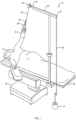
- FIG. 1 an exemplary limb positioning apparatus 10 of this disclosure is illustrated schematically, the component parts of which are described in more detail below.
- a patient 12 is shown lying on a standard operating table 22 and prepared for a surgical operation.
- the operating table 22 is supported by a suitable stand or support 24 on the floor of the operating room.
- the forearm of the arm 26 to be operated upon is encased within a sterile surgical drape assembly 28.
- a non-sterile, flexible drive shaft 30, which may be a metal cord, is secured to the drape assembly 28 and is routed through an elongated boom member 36.
- the boom member 36 may be in the form of a generally square tube, having a proximal end 32 and a distal end 34.
- the boom member 36 may be made of stainless steel or other suitable materials for maintaining an easily cleaned exterior surface.
- the boom member 36 is shown as fixedly secured to the operating table 22.
- the drive shaft 30 is threaded over a plurality of pulleys 40 at the distal end of the boom member 36 and is attached to the drape assembly 28 via a connector assembly 44.
- the connector assembly 44 is configured to connect the non-sterile drive shaft 30 and the sterile drape assembly 28, as further described below.
- Another flexible member which may be a wire rope 38, extends from the proximal end 32 of the boom member 36 and is configured to attach to selectively applied weights 14 in order to place the drive shaft 30 under tension and achieve the desired traction on the arm 26 of the patient 12.
- FIGS. 2A-C cut-away, detailed views of the boom member 36 are shown as viewed from the proximal end 32 ( FIG. 2A ) and the distal end 34 ( FIG. 2B-2C ).
- a carriage 46 is disposed within the boom member 36 and configured for axial movement therein.
- the carriage 46 may be a wheeled carriage.
- the wire rope 38 is attached a first side of the carriage 46 and extends toward the proximal end 32 of the boom member 36.
- the drive shaft 30 is attached to the opposite side of the carriage 46 and extends toward the distal end 34 of the boom member 36.
- the drive shaft 30 is rigidly mounted to the carriage 46 such that it cannot rotate about its longitudinal axis.
- the drive shaft 30 exits an aperture 52 in the boom member 36 and is routed over a plurality of pulleys 40a, 40b, 40c, 40d housed within an arcuate portion 48 attached to the distal end 34 of the boom member 36.
- the pulleys 40a, 40b, 40c, 40d provide an additional anti-rotational resistance to the drive shaft 30. While four pulleys are illustrated in FIG. 2C , more or fewer than four pulleys are contemplated by this disclosure.
- FIG. 3A is a further cut-away, detailed view of the boom member 36 as seen from the distal end 34.
- the wire rope 38 exits through an aperture (not shown) and is routed over a single pulley 42.
- a hook, thimble or other suitable member 39 is attached to the free end of the wire rope 38 to which counter-weights can be added.
- the receiver 50 is a hexagonally-shaped female receptor. However, other suitable shapes and configurations of the receiver 50 are contemplated by this disclosure.
- the hexagonal interior surface 51 of the receiver 50 can be seen in more detail in FIG. 3B .
- the receiver 50 may include a spring 53 or other element for releasable engagement with an insertion member, as further described below.
- the drive shaft 30 cannot rotate about its longitudinal axis, the receiver 50 is advantageously always in the same rotational orientation with respect to the carriage 46.
- the additional anti-rotation mechanism of the drive shaft 30 could also be built directly into the receiver 50.
- the resistance to rotation could be achieved by either a custom clutch mechanism or a commercially available clutch mechanism.
- drive shaft 30 benefits from freedom in the X, Y and Z directions while still maintaining controlled axial rotation.
- a sterile connection is needed to bridge the gap between the non-sterile, durable device and the sterile, patient-contacting drape. As illustrated in FIGS. 4A and 4B , this is accomplished by means of a two-ended sterile connector 54.
- the sterile connector 54 may be made of polymers, metals or other suitable materials and is intended to be disposed of after use.
- One end of the sterile connector 54 comprises a pin 56 for insertion into the receiver 50 of the drive shaft 30, as shown in FIG. 4B .
- the pin 56 may be a hex pin for insertion into the hexagonal interior 51 of the receiver 50.
- the pin 56 may be releasably secured inside the receiver via the spring 53 ( FIG. 3B ) or other suitable member.
- the other end of the sterile connector 54 includes a T-shaped projection 58, the purpose of which will be described in more detail below.
- the disposable drape assembly 28 consists of two parts, a cylindrical portion 60 and a wrap portion 62.
- Either or both of the cylindrical portion 60 and the wrap portion 62 may be made of polymers, metals, fibers or other suitable materials and are intended to be disposed of after use.
- the cylindrical portion 60 has an aperture 64 at one end configured to accept and align to the T-shaped projection 58.
- the wrap portion 62 contains a rigid plate 66 with an integrated sling 70, into which the hand of the patient's operative arm is secured.
- the sling 70 may be made of foam, rubber, fibers or other suitable materials.
- the rigid plate 66 contains a central aperture 68 for fitting over the cylindrical portion 60.
- the aperture 68 is configured to form an interference fit with the cylindrical portion 60 such that the drape assembly 28 may be rotated against the natural friction between the wrap portion 62 and the cylindrical portion 60.
- the friction is sufficient to maintain the patient's arm in the new position without requiring that it be manually held in place.
- FIG. 6 illustrates another example of a sterile connector 154 including an alternate anti-rotation mechanism.
- the sterile connector 154 may form part of the surgical drape assembly (not shown) and may be partially or fully covered by a sleeve (not shown).
- an approximate center of the sterile connector 154 comprises a latch 172 and a latch lock 174.
- Extending from the latch 172 is a first body portion 176 which is coupled to the T-shaped projection 158.
- Extending from the latch lock 176 is a second body portion 178 which is coupled to the pin 156.
- a torque insert 180 Disposed within the second body portion 178 of the sterile connector 154 is a torque insert 180.
- the torque insert 180 is may be a commerciallyavailable torque insert, such as a TI-300 Series Torque Insert manufactured by REELL Precision Manufacturing, Inc., St. Paul Minnesota.
- the torque insert 180 is connected to the pin 156 on one end and the T-shaped projection 158 on the other end.
- the torque insert 180 is non-sterile and is intended to be reusable.
- the anti-rotation mechanism of the disposable drape assembly 28, as discussed above with regard to FIG. 5B is thus directly incorporated as part of the sterile connector 154.
- this configuration reduces variability in the torque value due to component variations and environmental conditions (e.g., wet or dry) and also reduces costs of manufacturing. Additionally, it allows the entire surgical drape assembly to be disposable.
- FIG. 7 illustrates the complete connector assembly 44 (i.e., the receiver 50 and the connector 54, 154) attached to both the limb positioning apparatus 10 and the surgical drape assembly 28 as depicted in FIG. 1 .
- the connector assembly 44 advantageously allows the surgeon to operate the limb positioning apparatus 10 during surgery without compromising the sterile field. Additionally, the operative arm of the patient can be attached to and detached from the limb positioning apparatus 10 without compromising the sterile field.
Landscapes
- Health & Medical Sciences (AREA)
- Orthopedic Medicine & Surgery (AREA)
- Engineering & Computer Science (AREA)
- Biomedical Technology (AREA)
- Life Sciences & Earth Sciences (AREA)
- Animal Behavior & Ethology (AREA)
- General Health & Medical Sciences (AREA)
- Public Health (AREA)
- Veterinary Medicine (AREA)
- Nursing (AREA)
- Heart & Thoracic Surgery (AREA)
- Vascular Medicine (AREA)
- Accommodation For Nursing Or Treatment Tables (AREA)
Description
- This disclosure relates generally to devices which are used to position a limb of a patient during a medical procedure, and more particularly to devices which are used to position the shoulder and arm of a patient during shoulder surgery.
- Orthopedic shoulder surgery involves complexities not encountered in other surgeries, such as knee surgery. For example, during shoulder surgery, ports or incisions are placed through a patient's shoulder joint in order to provide access for instruments such as light sources, visual scopes, and surgical tools. However, it is sometimes desirable for a surgeon to gain access to a different area of the joint, without creating new ports, by rotating the operative limb and holding it in a new position. This is usually done manually by a physician's assistant who must rotate and hold the arm in a new fixed position for as long as needed to allow the surgeon to complete the required tasks. This prevents the assistant from doing anything else during this time, and can result in fatigue for the assistant, leading to inconsistent positioning of the patient's arm.
- Specialized mechanical positioning devices have been developed for supporting and positioning body parts during surgery. These devices may include a drape attached to the patient's limb from which a cord is routed through a boom member. The other end of the cord extending from the boom member is selectively weighted to apply tension to the cord and achieve the desired traction on the limb. However, adjusting these devices to obtain a new limb position may still require the use of an assistant, which may preclude optimal positioning of the limb. Furthermore, since maintaining a sterile surgical field during the operation is critical, it is a challenge to bridge the gap between the non-sterile positioning device and the sterile surgical drape.
-
US 8540656B1 discloses an apparatus for the treatment of fractures of the distal radius.GB1045471A - The invention is set out in the appended set of claims.
- Described herein is an apparatus that controls the rotation of an operative limb during shoulder surgery which includes a specially-designed, disposable wrap or drape attached to a flexible and non-rotating segment of a limb suspension system. The limb suspension system of this disclosure is composed of three parts: 1) a mechanism that is part of the durable apparatus, and which allows the limb to be suspended from the system and traction weights applied, but is configured in such a manner that the cable or other connecting member does not rotate about its axis; 2) a sterile connector that acts as the interface between the non-sterile, durable apparatus and a sterile, patient-contacting disposable drape; and 3) the disposable drape which is secured to the patient's operative arm. One of the sterile connector and the disposable drape contains a feature that allows the physician to rotate and hold the limb in any desired position, without requiring that it be manually held in place. Advantageously, the apparatus of this disclosure eliminates the need for an assistant while also maintaining a sterile field of operation.
- Further examples of the surgical limb positioning apparatus of this disclosure may include one or more of the following, in any suitable combination.
- Examples of the surgical limb positioning apparatus of this disclosure include an elongated, hollow boom member having a proximal end, a distal end and a longitudinal axis extending therebetween. The apparatus has a carriage disposed within the boom member and moveable along the longitudinal axis. The apparatus further includes a first flexible member attached to a first side of the carriage and exiting the boom member at a first aperture located at the proximal end of the boom member. A free end of the first flexible member is configured for attachment to a weight. The apparatus further has a second flexible member attached to a second side of the carriage such that the flexible member cannot rotate relative to the longitudinal axis of the boom member. The second flexible member exits the boom member at a second aperture located at the distal end of the boom member. The apparatus yet further includes a connector assembly attached to a free end of the second flexible member for forming a sterile connection to a drape assembly. One of the connector assembly and the drape assembly has an anti-rotation mechanism configured to maintain an operative limb of a patient in a pre-selected position.
- In further examples of the apparatus, the boom member is a generally square tube and the carriage is a wheeled carriage. The first flexible member is a wire rope and the second flexible member is a metal cord. The apparatus further includes an arcuate portion attached to the distal end of the boom member. The second flexible member is routed through a plurality of pulleys housed within the arcuate portion. The pulleys provide an additional anti-rotational resistance to the second flexible member. In examples, the connector assembly includes a receiver attached to the free end of the second flexible member and a connector for releasably coupling to the receiver. A first end of the connector includes a pin, and the receiver has an opening for receiving the pin. A second end of the connector comprises a projection, and the drape assembly has an aperture for releasably coupling to the projection. At least a portion of the connector is sterile. In examples, the anti-rotation mechanism is a torque insert disposed within the connector.
- Examples of a connector assembly for use with a limb positioning apparatus of this disclosure include a receiver attached to a free end of a flexible member of the limb positioning apparatus and a connector for releasably coupling to the receiver. A first end of the connector includes a pin, and a second end of the connector includes a projection. The receiver has an opening for receiving the pin, while a drape assembly for retaining an operative limb of a patient has an aperture for releasably coupling to the projection. In examples, the projection is a T-shaped projection. The connector has an anti-rotation mechanism configured to maintain the operative limb of the patient in a pre-selected position. In examples, the anti-rotation mechanism is a torque insert disposed within the connector.
- Examples of a method of positioning a limb during surgery of this disclosure include disposing an operative limb of a patient within a drape assembly of a limb positioning apparatus as described above and rotating the operative limb of the patient to a pre-selected position. The anti-rotation mechanism is configured to maintain the operative limb of the patient in the pre-selected position. In examples, the anti-rotation mechanism is a torque insert disposed within the connector.
- These and other features and advantages will be apparent from a reading of the following detailed description and a review of the associated drawings. It is to be understood that both the foregoing general description and the following detailed description are explanatory only and are not restrictive of aspects as claimed.
- The disclosure will be more fully understood by reference to the detailed description, in conjunction with the following figures, wherein:
-
FIG. 1 is a perspective view illustrating the use of the limb positioning apparatus of this disclosure; -
FIGS. 2A-C are detailed views of examples of the boom member of the apparatus of -
FIG. 1 ; -
FIGS. 3A-3B are detailed views of the distal end of the boom member ofFIGS. 2A-C ; -
FIGS. 4A-4B illustrate an example of the sterile connector of the apparatus ofFIG. 1 ; -
FIGS. 5A-5B illustrate an example of the surgical drape assembly of the apparatus ofFIG. 1 ; -
FIG. 6 illustrates an alternative example of the sterile connector ofFIGS. 4A-4B ; and -
FIG. 7 illustrates the connector assembly attached to the surgical drape assembly and the limb positioning apparatus ofFIG. 1 . - In the description that follows, like components have been given the same reference numerals, regardless of whether they are shown in different examples. To illustrate example(s) in a clear and concise manner, the drawings may not necessarily be to scale and certain features may be shown in somewhat schematic form. Features that are described and/or illustrated with respect to one example may be used in the same way or in a similar way in one or more other examples and/or in combination with or instead of the features of the other examples.
- As used in the specification and claims, for the purposes of describing and defining the invention, the terms "about" and "substantially" represent the inherent degree of uncertainty that may be attributed to any quantitative comparison, value, measurement, or other representation. The terms "about" and "substantially" are also used herein to represent the degree by which a quantitative representation may vary from a stated reference without resulting in a change in the basic function of the subject matter at issue. "Comprise," "include," and/or plural forms of each are open ended and include the listed parts and can include additional parts that are not listed. "And/or" is open-ended and includes one or more of the listed parts and combinations of the listed parts.
- Referring now to
FIG. 1 , an exemplarylimb positioning apparatus 10 of this disclosure is illustrated schematically, the component parts of which are described in more detail below. InFIG. 1 , apatient 12 is shown lying on a standard operating table 22 and prepared for a surgical operation. The operating table 22 is supported by a suitable stand orsupport 24 on the floor of the operating room. The forearm of thearm 26 to be operated upon is encased within a sterilesurgical drape assembly 28. A non-sterile,flexible drive shaft 30, which may be a metal cord, is secured to thedrape assembly 28 and is routed through anelongated boom member 36. Theboom member 36 may be in the form of a generally square tube, having aproximal end 32 and adistal end 34. Theboom member 36 may be made of stainless steel or other suitable materials for maintaining an easily cleaned exterior surface. - In
FIG. 1 , theboom member 36 is shown as fixedly secured to the operating table 22. Thedrive shaft 30 is threaded over a plurality ofpulleys 40 at the distal end of theboom member 36 and is attached to thedrape assembly 28 via aconnector assembly 44. Theconnector assembly 44 is configured to connect thenon-sterile drive shaft 30 and thesterile drape assembly 28, as further described below. Another flexible member, which may be awire rope 38, extends from theproximal end 32 of theboom member 36 and is configured to attach to selectively appliedweights 14 in order to place thedrive shaft 30 under tension and achieve the desired traction on thearm 26 of thepatient 12. - Turning now to
FIGS. 2A-C , cut-away, detailed views of theboom member 36 are shown as viewed from the proximal end 32 (FIG. 2A ) and the distal end 34 (FIG. 2B-2C ). InFIG. 2A , it can be seen that acarriage 46 is disposed within theboom member 36 and configured for axial movement therein. For example, thecarriage 46 may be a wheeled carriage. Thewire rope 38 is attached a first side of thecarriage 46 and extends toward theproximal end 32 of theboom member 36. Thedrive shaft 30 is attached to the opposite side of thecarriage 46 and extends toward thedistal end 34 of theboom member 36. Notably, thedrive shaft 30 is rigidly mounted to thecarriage 46 such that it cannot rotate about its longitudinal axis. Moreover, as shown inFIG. 2C , thedrive shaft 30 exits anaperture 52 in theboom member 36 and is routed over a plurality ofpulleys arcuate portion 48 attached to thedistal end 34 of theboom member 36. Thepulleys drive shaft 30. While four pulleys are illustrated inFIG. 2C , more or fewer than four pulleys are contemplated by this disclosure. -
FIG. 3A is a further cut-away, detailed view of theboom member 36 as seen from thedistal end 34. At theproximal end 32 of theboom member 36, thewire rope 38 exits through an aperture (not shown) and is routed over asingle pulley 42. A hook, thimble or othersuitable member 39 is attached to the free end of thewire rope 38 to which counter-weights can be added. At the free end of thedrive shaft 30 is a rigidly-mountedreceiver 50. InFIG . 3A , thereceiver 50 is a hexagonally-shaped female receptor. However, other suitable shapes and configurations of thereceiver 50 are contemplated by this disclosure. - The hexagonal
interior surface 51 of thereceiver 50 can be seen in more detail inFIG. 3B . As shown inFIG. 3B , thereceiver 50 may include a spring 53 or other element for releasable engagement with an insertion member, as further described below. Because thedrive shaft 30 cannot rotate about its longitudinal axis, thereceiver 50 is advantageously always in the same rotational orientation with respect to thecarriage 46. In other examples, not shown, the additional anti-rotation mechanism of thedrive shaft 30 could also be built directly into thereceiver 50. For example, the resistance to rotation could be achieved by either a custom clutch mechanism or a commercially available clutch mechanism. Thus, driveshaft 30 benefits from freedom in the X, Y and Z directions while still maintaining controlled axial rotation. - As discussed above, during an operation, a sterile connection is needed to bridge the gap between the non-sterile, durable device and the sterile, patient-contacting drape. As illustrated in
FIGS. 4A and 4B , this is accomplished by means of a two-endedsterile connector 54. Thesterile connector 54 may be made of polymers, metals or other suitable materials and is intended to be disposed of after use. One end of thesterile connector 54 comprises apin 56 for insertion into thereceiver 50 of thedrive shaft 30, as shown inFIG. 4B . For example, thepin 56 may be a hex pin for insertion into thehexagonal interior 51 of thereceiver 50. Thepin 56 may be releasably secured inside the receiver via the spring 53 (FIG. 3B ) or other suitable member. The other end of thesterile connector 54 includes a T-shapedprojection 58, the purpose of which will be described in more detail below. - Turning now to
FIG. 5A , it can be seen that thedisposable drape assembly 28 consists of two parts, acylindrical portion 60 and awrap portion 62. Either or both of thecylindrical portion 60 and thewrap portion 62 may be made of polymers, metals, fibers or other suitable materials and are intended to be disposed of after use. As shown inFIG. 5B , thecylindrical portion 60 has anaperture 64 at one end configured to accept and align to the T-shapedprojection 58. Thewrap portion 62 contains arigid plate 66 with anintegrated sling 70, into which the hand of the patient's operative arm is secured. Thesling 70 may be made of foam, rubber, fibers or other suitable materials. Therigid plate 66 contains acentral aperture 68 for fitting over thecylindrical portion 60. Importantly, theaperture 68 is configured to form an interference fit with thecylindrical portion 60 such that thedrape assembly 28 may be rotated against the natural friction between thewrap portion 62 and thecylindrical portion 60. Advantageously, the friction is sufficient to maintain the patient's arm in the new position without requiring that it be manually held in place. -
FIG. 6 illustrates another example of asterile connector 154 including an alternate anti-rotation mechanism. Thesterile connector 154 may form part of the surgical drape assembly (not shown) and may be partially or fully covered by a sleeve (not shown). As seen inFIG. 6 , an approximate center of thesterile connector 154 comprises alatch 172 and alatch lock 174. Extending from thelatch 172 is afirst body portion 176 which is coupled to the T-shapedprojection 158. Extending from thelatch lock 176 is asecond body portion 178 which is coupled to thepin 156. Disposed within thesecond body portion 178 of thesterile connector 154 is atorque insert 180. Thetorque insert 180 is may be a commerciallyavailable torque insert, such as a TI-300 Series Torque Insert manufactured by REELL Precision Manufacturing, Inc., St. Paul Minnesota. Thetorque insert 180 is connected to thepin 156 on one end and the T-shapedprojection 158 on the other end. Thetorque insert 180 is non-sterile and is intended to be reusable. In this example, the anti-rotation mechanism of thedisposable drape assembly 28, as discussed above with regard toFIG. 5B , is thus directly incorporated as part of thesterile connector 154. Advantageously, this configuration reduces variability in the torque value due to component variations and environmental conditions (e.g., wet or dry) and also reduces costs of manufacturing. Additionally, it allows the entire surgical drape assembly to be disposable. -
FIG. 7 illustrates the complete connector assembly 44 (i.e., thereceiver 50 and theconnector 54, 154) attached to both thelimb positioning apparatus 10 and thesurgical drape assembly 28 as depicted inFIG. 1 . Theconnector assembly 44 advantageously allows the surgeon to operate thelimb positioning apparatus 10 during surgery without compromising the sterile field. Additionally, the operative arm of the patient can be attached to and detached from thelimb positioning apparatus 10 without compromising the sterile field. - While this disclosure has been particularly shown and described with references to preferred embodiments thereof, it will be understood by those skilled in the art that various changes in form and details may be made therein without departing from the scope of the present application as defined by the appended claims. Such variations are intended to be covered by the scope of this present application. As such, the foregoing description of embodiments of the present application is not intended to be limiting, the full scope rather being conveyed by the appended claims.
Claims (11)
- A surgical limb positioning apparatus (10) comprising:an elongated, hollow boom member (36) having a proximal end (32), a distal end (34) and a longitudinal axis extending therebetween;a carriage (46) disposed within the boom member (36) and moveable along the longitudinal axis;a first flexible member (38) attached to a first side of the carriage (46) and exiting the boom member (36) at a first aperture located at the proximal end (32) of the boom member (36);a second flexible member (30) attached to a second side of the carriage (46) such that the flexible member cannot rotate relative to the longitudinal axis of the boom member, the second flexible member (30) exiting the boom member at a second aperture located at the distal end (34) of the boom member (36);a connector assembly (44) attached to a free end of the second flexible member (30); and a drape assembly (28);characterized in that:a free end of the first flexible member (38) is configured for attachment to a weight (14);the connector assembly (44) is for forming a sterile connection to a drape assembly (28), andwherein one of the connector assembly (44) and the drape assembly (28) comprises an anti-rotation mechanism configured to maintain an operative limb (26) of a patient (12) in a pre-selected position.
- The apparatus of claim 1, wherein the boom member (36) is a generally square tube.
- The apparatus of claim 1, wherein the carriage (46) is a wheeled carriage.
- The apparatus of claim 1, wherein the first flexible member (28) is a wire rope.
- The apparatus of claim 1, wherein the second flexible member (30) is a metal cord.
- The apparatus of claim 1, further comprising an arcuate portion (48) attached to the distal end (34) of the boom member (36), the second flexible member (30) being routed through a plurality of pulleys (40a-d) housed within the arcuate portion (48), the pulleys (40a-d) providing an additional anti-rotational resistance to the second flexible member (30).
- The apparatus of claim 1, wherein the connector assembly (44) comprises a receiver (50) attached to the free end of the second flexible member (30) and a connector (54, 154) for releasably coupling to the receiver (50).
- The apparatus of claim 7, wherein a first end of the connector (54, 154) comprises a pin (56, 156), and the receiver (50) comprises an opening for receiving the pin (56, 156).
- The apparatus of claim 7, wherein a second end of the connector comprises a projection (58, 158), and the drape assembly (28) comprises an aperture (64) for releasably coupling to the projection (58, 158).
- The apparatus of claim 7, wherein at least a portion of the connector (54, 154) is sterile.
- The apparatus of claim 7, wherein the anti-rotation mechanism is a torque insert disposed (180) within the connector (154).
Applications Claiming Priority (2)
| Application Number | Priority Date | Filing Date | Title |
|---|---|---|---|
| US201762449724P | 2017-01-24 | 2017-01-24 | |
| PCT/US2018/014663 WO2018140346A1 (en) | 2017-01-24 | 2018-01-22 | Surgical limb positioning apparatus |
Publications (2)
| Publication Number | Publication Date |
|---|---|
| EP3573590A1 EP3573590A1 (en) | 2019-12-04 |
| EP3573590B1 true EP3573590B1 (en) | 2023-06-07 |
Family
ID=61224502
Family Applications (1)
| Application Number | Title | Priority Date | Filing Date |
|---|---|---|---|
| EP18705198.2A Active EP3573590B1 (en) | 2017-01-24 | 2018-01-22 | Surgical limb positioning apparatus |
Country Status (6)
| Country | Link |
|---|---|
| US (1) | US11090213B2 (en) |
| EP (1) | EP3573590B1 (en) |
| JP (1) | JP7058661B2 (en) |
| CN (1) | CN110167502B (en) |
| AU (1) | AU2018213039B2 (en) |
| WO (1) | WO2018140346A1 (en) |
Families Citing this family (5)
| Publication number | Priority date | Publication date | Assignee | Title |
|---|---|---|---|---|
| EP3706701B1 (en) * | 2017-11-08 | 2022-01-05 | Smith & Nephew, Inc. | Surgical hand wrap |
| US10918552B2 (en) | 2019-05-21 | 2021-02-16 | Smith & Nephew, Inc. | Limb positioning apparatus and methods of use thereof |
| CN112155925B (en) * | 2020-10-22 | 2022-04-01 | 宁波科艺医疗器械有限公司 | Shoulder joint traction frame |
| WO2022129363A1 (en) * | 2020-12-17 | 2022-06-23 | Stavanger Universitetssjukehus | Limb holding device |
| KR102785133B1 (en) * | 2024-10-17 | 2025-03-27 | 주식회사 비에이치서지컬 | Surgical auxiliary band providing improved fixation |
Family Cites Families (11)
| Publication number | Priority date | Publication date | Assignee | Title |
|---|---|---|---|---|
| US2720878A (en) * | 1953-10-09 | 1955-10-18 | Earl L Hickman | Adjustable foot rest for polio bed patients |
| GB1045471A (en) * | 1964-12-21 | 1966-10-12 | Roy Homer Maudsley | Orthopaedic appliances |
| US4616637A (en) * | 1984-09-14 | 1986-10-14 | Precision Surgical Instruments, Inc. | Shoulder traction apparatus |
| US5003967A (en) * | 1988-03-25 | 1991-04-02 | Mcconnell Bernard E | Hand traction wrap |
| US4930523A (en) * | 1989-04-13 | 1990-06-05 | Lincoln Mills, Inc. | Surgical shoulder positioning apparatus |
| CN2189914Y (en) * | 1993-09-30 | 1995-02-22 | 葛长娟 | Cervical tractor |
| US5775334A (en) | 1996-03-15 | 1998-07-07 | Orthopedic Systems, Inc. | Limb positioning apparatus for surgery |
| JP2004337439A (en) * | 2003-05-16 | 2004-12-02 | Shizuhito Yamamoto | Spinal orthotic device |
| CN201131831Y (en) * | 2008-01-05 | 2008-10-15 | 李广义 | Double-ankle suspension reset device |
| US8273047B1 (en) | 2008-11-19 | 2012-09-25 | Perseus Athletic, LLC | Adjusting and applying traction to a patient's arm |
| US8540656B1 (en) * | 2012-01-26 | 2013-09-24 | Roy Y. Powlan | Apparatus and method for the treatment of fractures of the distal radius |
-
2018
- 2018-01-22 AU AU2018213039A patent/AU2018213039B2/en active Active
- 2018-01-22 EP EP18705198.2A patent/EP3573590B1/en active Active
- 2018-01-22 US US16/475,844 patent/US11090213B2/en active Active
- 2018-01-22 WO PCT/US2018/014663 patent/WO2018140346A1/en not_active Ceased
- 2018-01-22 JP JP2019537363A patent/JP7058661B2/en active Active
- 2018-01-22 CN CN201880005963.7A patent/CN110167502B/en active Active
Also Published As
| Publication number | Publication date |
|---|---|
| US11090213B2 (en) | 2021-08-17 |
| EP3573590A1 (en) | 2019-12-04 |
| CN110167502A (en) | 2019-08-23 |
| JP2020513932A (en) | 2020-05-21 |
| US20190350792A1 (en) | 2019-11-21 |
| AU2018213039B2 (en) | 2023-07-20 |
| JP7058661B2 (en) | 2022-04-22 |
| CN110167502B (en) | 2022-05-17 |
| WO2018140346A1 (en) | 2018-08-02 |
| AU2018213039A1 (en) | 2019-07-11 |
Similar Documents
| Publication | Publication Date | Title |
|---|---|---|
| AU2018213039B2 (en) | Surgical limb positioning apparatus | |
| US20220346908A1 (en) | Adjustable retaining arm system | |
| ES2971504T3 (en) | Robotic microsurgery set and operating area | |
| US7435219B2 (en) | Surgical retractor positioning device | |
| US4573452A (en) | Surgical holder for a laparoscope or the like | |
| US7226413B2 (en) | Nerve root retractor and sucker | |
| US8074657B2 (en) | Surgical drape system | |
| CN110996834B (en) | Supports for medical devices | |
| KR101907176B1 (en) | Suction Auxiliary Equipment | |
| CA2247076A1 (en) | Articulating guide arm for medical applications | |
| KR970061211A (en) | Surgical Instruments and Surgical Methods to Stabilize the Pulsating Heart During Coronary Artery Graft Surgery | |
| WO2007047506A2 (en) | Biomedical positioning and stabilization system | |
| CN105592801A (en) | Control unit for medical device | |
| ES2878803T3 (en) | Endoscope Tool Position Holder | |
| US20160199087A1 (en) | Adjustable tissue cutter tool | |
| US5010900A (en) | Lower limb positioning apparatus and surgical drape | |
| EP3706701B1 (en) | Surgical hand wrap | |
| JP2019069135A (en) | Surgical retractor | |
| EP3741344A1 (en) | Limb positioning apparatus and methods of use thereof | |
| JP2005253987A (en) | Holding device | |
| CN116322552A (en) | Interfaces to Surgical Robotic Arms and Instruments | |
| CN224039344U (en) | Traction device for wrist minimally invasive surgery | |
| CN213722158U (en) | A retractor for orthopaedic clinical surgery | |
| US20060293568A1 (en) | Collapsible surgical tool bar | |
| US11369442B2 (en) | Surgical system |
Legal Events
| Date | Code | Title | Description |
|---|---|---|---|
| STAA | Information on the status of an ep patent application or granted ep patent |
Free format text: STATUS: UNKNOWN |
|
| STAA | Information on the status of an ep patent application or granted ep patent |
Free format text: STATUS: THE INTERNATIONAL PUBLICATION HAS BEEN MADE |
|
| PUAI | Public reference made under article 153(3) epc to a published international application that has entered the european phase |
Free format text: ORIGINAL CODE: 0009012 |
|
| STAA | Information on the status of an ep patent application or granted ep patent |
Free format text: STATUS: REQUEST FOR EXAMINATION WAS MADE |
|
| 17P | Request for examination filed |
Effective date: 20190826 |
|
| AK | Designated contracting states |
Kind code of ref document: A1 Designated state(s): AL AT BE BG CH CY CZ DE DK EE ES FI FR GB GR HR HU IE IS IT LI LT LU LV MC MK MT NL NO PL PT RO RS SE SI SK SM TR |
|
| AX | Request for extension of the european patent |
Extension state: BA ME |
|
| DAV | Request for validation of the european patent (deleted) | ||
| DAX | Request for extension of the european patent (deleted) | ||
| STAA | Information on the status of an ep patent application or granted ep patent |
Free format text: STATUS: EXAMINATION IS IN PROGRESS |
|
| 17Q | First examination report despatched |
Effective date: 20220608 |
|
| GRAP | Despatch of communication of intention to grant a patent |
Free format text: ORIGINAL CODE: EPIDOSNIGR1 |
|
| STAA | Information on the status of an ep patent application or granted ep patent |
Free format text: STATUS: GRANT OF PATENT IS INTENDED |
|
| INTG | Intention to grant announced |
Effective date: 20230105 |
|
| GRAS | Grant fee paid |
Free format text: ORIGINAL CODE: EPIDOSNIGR3 |
|
| GRAA | (expected) grant |
Free format text: ORIGINAL CODE: 0009210 |
|
| STAA | Information on the status of an ep patent application or granted ep patent |
Free format text: STATUS: THE PATENT HAS BEEN GRANTED |
|
| AK | Designated contracting states |
Kind code of ref document: B1 Designated state(s): AL AT BE BG CH CY CZ DE DK EE ES FI FR GB GR HR HU IE IS IT LI LT LU LV MC MK MT NL NO PL PT RO RS SE SI SK SM TR |
|
| REG | Reference to a national code |
Ref country code: GB Ref legal event code: FG4D |
|
| REG | Reference to a national code |
Ref country code: CH Ref legal event code: EP Ref country code: AT Ref legal event code: REF Ref document number: 1572674 Country of ref document: AT Kind code of ref document: T Effective date: 20230615 Ref country code: DE Ref legal event code: R096 Ref document number: 602018050887 Country of ref document: DE |
|
| P01 | Opt-out of the competence of the unified patent court (upc) registered |
Effective date: 20230526 |
|
| REG | Reference to a national code |
Ref country code: LT Ref legal event code: MG9D |
|
| REG | Reference to a national code |
Ref country code: NL Ref legal event code: MP Effective date: 20230607 |
|
| PG25 | Lapsed in a contracting state [announced via postgrant information from national office to epo] |
Ref country code: SE Free format text: LAPSE BECAUSE OF FAILURE TO SUBMIT A TRANSLATION OF THE DESCRIPTION OR TO PAY THE FEE WITHIN THE PRESCRIBED TIME-LIMIT Effective date: 20230607 Ref country code: NO Free format text: LAPSE BECAUSE OF FAILURE TO SUBMIT A TRANSLATION OF THE DESCRIPTION OR TO PAY THE FEE WITHIN THE PRESCRIBED TIME-LIMIT Effective date: 20230907 Ref country code: ES Free format text: LAPSE BECAUSE OF FAILURE TO SUBMIT A TRANSLATION OF THE DESCRIPTION OR TO PAY THE FEE WITHIN THE PRESCRIBED TIME-LIMIT Effective date: 20230607 |
|
| REG | Reference to a national code |
Ref country code: AT Ref legal event code: MK05 Ref document number: 1572674 Country of ref document: AT Kind code of ref document: T Effective date: 20230607 |
|
| PG25 | Lapsed in a contracting state [announced via postgrant information from national office to epo] |
Ref country code: RS Free format text: LAPSE BECAUSE OF FAILURE TO SUBMIT A TRANSLATION OF THE DESCRIPTION OR TO PAY THE FEE WITHIN THE PRESCRIBED TIME-LIMIT Effective date: 20230607 Ref country code: NL Free format text: LAPSE BECAUSE OF FAILURE TO SUBMIT A TRANSLATION OF THE DESCRIPTION OR TO PAY THE FEE WITHIN THE PRESCRIBED TIME-LIMIT Effective date: 20230607 Ref country code: LV Free format text: LAPSE BECAUSE OF FAILURE TO SUBMIT A TRANSLATION OF THE DESCRIPTION OR TO PAY THE FEE WITHIN THE PRESCRIBED TIME-LIMIT Effective date: 20230607 Ref country code: LT Free format text: LAPSE BECAUSE OF FAILURE TO SUBMIT A TRANSLATION OF THE DESCRIPTION OR TO PAY THE FEE WITHIN THE PRESCRIBED TIME-LIMIT Effective date: 20230607 Ref country code: HR Free format text: LAPSE BECAUSE OF FAILURE TO SUBMIT A TRANSLATION OF THE DESCRIPTION OR TO PAY THE FEE WITHIN THE PRESCRIBED TIME-LIMIT Effective date: 20230607 Ref country code: GR Free format text: LAPSE BECAUSE OF FAILURE TO SUBMIT A TRANSLATION OF THE DESCRIPTION OR TO PAY THE FEE WITHIN THE PRESCRIBED TIME-LIMIT Effective date: 20230908 |
|
| PG25 | Lapsed in a contracting state [announced via postgrant information from national office to epo] |
Ref country code: FI Free format text: LAPSE BECAUSE OF FAILURE TO SUBMIT A TRANSLATION OF THE DESCRIPTION OR TO PAY THE FEE WITHIN THE PRESCRIBED TIME-LIMIT Effective date: 20230607 |
|
| PG25 | Lapsed in a contracting state [announced via postgrant information from national office to epo] |
Ref country code: SK Free format text: LAPSE BECAUSE OF FAILURE TO SUBMIT A TRANSLATION OF THE DESCRIPTION OR TO PAY THE FEE WITHIN THE PRESCRIBED TIME-LIMIT Effective date: 20230607 |
|
| PG25 | Lapsed in a contracting state [announced via postgrant information from national office to epo] |
Ref country code: IS Free format text: LAPSE BECAUSE OF FAILURE TO SUBMIT A TRANSLATION OF THE DESCRIPTION OR TO PAY THE FEE WITHIN THE PRESCRIBED TIME-LIMIT Effective date: 20231007 |
|
| PG25 | Lapsed in a contracting state [announced via postgrant information from national office to epo] |
Ref country code: SM Free format text: LAPSE BECAUSE OF FAILURE TO SUBMIT A TRANSLATION OF THE DESCRIPTION OR TO PAY THE FEE WITHIN THE PRESCRIBED TIME-LIMIT Effective date: 20230607 Ref country code: SK Free format text: LAPSE BECAUSE OF FAILURE TO SUBMIT A TRANSLATION OF THE DESCRIPTION OR TO PAY THE FEE WITHIN THE PRESCRIBED TIME-LIMIT Effective date: 20230607 Ref country code: RO Free format text: LAPSE BECAUSE OF FAILURE TO SUBMIT A TRANSLATION OF THE DESCRIPTION OR TO PAY THE FEE WITHIN THE PRESCRIBED TIME-LIMIT Effective date: 20230607 Ref country code: PT Free format text: LAPSE BECAUSE OF FAILURE TO SUBMIT A TRANSLATION OF THE DESCRIPTION OR TO PAY THE FEE WITHIN THE PRESCRIBED TIME-LIMIT Effective date: 20231009 Ref country code: IS Free format text: LAPSE BECAUSE OF FAILURE TO SUBMIT A TRANSLATION OF THE DESCRIPTION OR TO PAY THE FEE WITHIN THE PRESCRIBED TIME-LIMIT Effective date: 20231007 Ref country code: EE Free format text: LAPSE BECAUSE OF FAILURE TO SUBMIT A TRANSLATION OF THE DESCRIPTION OR TO PAY THE FEE WITHIN THE PRESCRIBED TIME-LIMIT Effective date: 20230607 Ref country code: CZ Free format text: LAPSE BECAUSE OF FAILURE TO SUBMIT A TRANSLATION OF THE DESCRIPTION OR TO PAY THE FEE WITHIN THE PRESCRIBED TIME-LIMIT Effective date: 20230607 Ref country code: AT Free format text: LAPSE BECAUSE OF FAILURE TO SUBMIT A TRANSLATION OF THE DESCRIPTION OR TO PAY THE FEE WITHIN THE PRESCRIBED TIME-LIMIT Effective date: 20230607 |
|
| PG25 | Lapsed in a contracting state [announced via postgrant information from national office to epo] |
Ref country code: PL Free format text: LAPSE BECAUSE OF FAILURE TO SUBMIT A TRANSLATION OF THE DESCRIPTION OR TO PAY THE FEE WITHIN THE PRESCRIBED TIME-LIMIT Effective date: 20230607 |
|
| REG | Reference to a national code |
Ref country code: DE Ref legal event code: R097 Ref document number: 602018050887 Country of ref document: DE |
|
| PLBE | No opposition filed within time limit |
Free format text: ORIGINAL CODE: 0009261 |
|
| STAA | Information on the status of an ep patent application or granted ep patent |
Free format text: STATUS: NO OPPOSITION FILED WITHIN TIME LIMIT |
|
| PG25 | Lapsed in a contracting state [announced via postgrant information from national office to epo] |
Ref country code: DK Free format text: LAPSE BECAUSE OF FAILURE TO SUBMIT A TRANSLATION OF THE DESCRIPTION OR TO PAY THE FEE WITHIN THE PRESCRIBED TIME-LIMIT Effective date: 20230607 |
|
| PG25 | Lapsed in a contracting state [announced via postgrant information from national office to epo] |
Ref country code: SI Free format text: LAPSE BECAUSE OF FAILURE TO SUBMIT A TRANSLATION OF THE DESCRIPTION OR TO PAY THE FEE WITHIN THE PRESCRIBED TIME-LIMIT Effective date: 20230607 |
|
| 26N | No opposition filed |
Effective date: 20240308 |
|
| PG25 | Lapsed in a contracting state [announced via postgrant information from national office to epo] |
Ref country code: SI Free format text: LAPSE BECAUSE OF FAILURE TO SUBMIT A TRANSLATION OF THE DESCRIPTION OR TO PAY THE FEE WITHIN THE PRESCRIBED TIME-LIMIT Effective date: 20230607 Ref country code: IT Free format text: LAPSE BECAUSE OF FAILURE TO SUBMIT A TRANSLATION OF THE DESCRIPTION OR TO PAY THE FEE WITHIN THE PRESCRIBED TIME-LIMIT Effective date: 20230607 |
|
| PG25 | Lapsed in a contracting state [announced via postgrant information from national office to epo] |
Ref country code: MC Free format text: LAPSE BECAUSE OF FAILURE TO SUBMIT A TRANSLATION OF THE DESCRIPTION OR TO PAY THE FEE WITHIN THE PRESCRIBED TIME-LIMIT Effective date: 20230607 |
|
| PG25 | Lapsed in a contracting state [announced via postgrant information from national office to epo] |
Ref country code: MC Free format text: LAPSE BECAUSE OF FAILURE TO SUBMIT A TRANSLATION OF THE DESCRIPTION OR TO PAY THE FEE WITHIN THE PRESCRIBED TIME-LIMIT Effective date: 20230607 |
|
| REG | Reference to a national code |
Ref country code: CH Ref legal event code: PL |
|
| PG25 | Lapsed in a contracting state [announced via postgrant information from national office to epo] |
Ref country code: LU Free format text: LAPSE BECAUSE OF NON-PAYMENT OF DUE FEES Effective date: 20240122 |
|
| PG25 | Lapsed in a contracting state [announced via postgrant information from national office to epo] |
Ref country code: LU Free format text: LAPSE BECAUSE OF NON-PAYMENT OF DUE FEES Effective date: 20240122 |
|
| PG25 | Lapsed in a contracting state [announced via postgrant information from national office to epo] |
Ref country code: BE Free format text: LAPSE BECAUSE OF NON-PAYMENT OF DUE FEES Effective date: 20240131 |
|
| PG25 | Lapsed in a contracting state [announced via postgrant information from national office to epo] |
Ref country code: CH Free format text: LAPSE BECAUSE OF NON-PAYMENT OF DUE FEES Effective date: 20240131 |
|
| PG25 | Lapsed in a contracting state [announced via postgrant information from national office to epo] |
Ref country code: CH Free format text: LAPSE BECAUSE OF NON-PAYMENT OF DUE FEES Effective date: 20240131 Ref country code: BE Free format text: LAPSE BECAUSE OF NON-PAYMENT OF DUE FEES Effective date: 20240131 |
|
| REG | Reference to a national code |
Ref country code: BE Ref legal event code: MM Effective date: 20240131 |
|
| PG25 | Lapsed in a contracting state [announced via postgrant information from national office to epo] |
Ref country code: BG Free format text: LAPSE BECAUSE OF FAILURE TO SUBMIT A TRANSLATION OF THE DESCRIPTION OR TO PAY THE FEE WITHIN THE PRESCRIBED TIME-LIMIT Effective date: 20230607 |
|
| PG25 | Lapsed in a contracting state [announced via postgrant information from national office to epo] |
Ref country code: BG Free format text: LAPSE BECAUSE OF FAILURE TO SUBMIT A TRANSLATION OF THE DESCRIPTION OR TO PAY THE FEE WITHIN THE PRESCRIBED TIME-LIMIT Effective date: 20230607 |
|
| PG25 | Lapsed in a contracting state [announced via postgrant information from national office to epo] |
Ref country code: IE Free format text: LAPSE BECAUSE OF NON-PAYMENT OF DUE FEES Effective date: 20240122 |
|
| PG25 | Lapsed in a contracting state [announced via postgrant information from national office to epo] |
Ref country code: IE Free format text: LAPSE BECAUSE OF NON-PAYMENT OF DUE FEES Effective date: 20240122 |
|
| PG25 | Lapsed in a contracting state [announced via postgrant information from national office to epo] |
Ref country code: CY Free format text: LAPSE BECAUSE OF FAILURE TO SUBMIT A TRANSLATION OF THE DESCRIPTION OR TO PAY THE FEE WITHIN THE PRESCRIBED TIME-LIMIT; INVALID AB INITIO Effective date: 20180122 |
|
| PG25 | Lapsed in a contracting state [announced via postgrant information from national office to epo] |
Ref country code: HU Free format text: LAPSE BECAUSE OF FAILURE TO SUBMIT A TRANSLATION OF THE DESCRIPTION OR TO PAY THE FEE WITHIN THE PRESCRIBED TIME-LIMIT; INVALID AB INITIO Effective date: 20180122 |
|
| PG25 | Lapsed in a contracting state [announced via postgrant information from national office to epo] |
Ref country code: TR Free format text: LAPSE BECAUSE OF FAILURE TO SUBMIT A TRANSLATION OF THE DESCRIPTION OR TO PAY THE FEE WITHIN THE PRESCRIBED TIME-LIMIT Effective date: 20230607 |
|
| PGFP | Annual fee paid to national office [announced via postgrant information from national office to epo] |
Ref country code: GB Payment date: 20251218 Year of fee payment: 9 |
|
| PGFP | Annual fee paid to national office [announced via postgrant information from national office to epo] |
Ref country code: FR Payment date: 20251222 Year of fee payment: 9 |
|
| PGFP | Annual fee paid to national office [announced via postgrant information from national office to epo] |
Ref country code: DE Payment date: 20251216 Year of fee payment: 9 |