EP3573253B1 - Wireless communication method, terminal device and network device - Google Patents
Wireless communication method, terminal device and network device Download PDFInfo
- Publication number
- EP3573253B1 EP3573253B1 EP17896101.7A EP17896101A EP3573253B1 EP 3573253 B1 EP3573253 B1 EP 3573253B1 EP 17896101 A EP17896101 A EP 17896101A EP 3573253 B1 EP3573253 B1 EP 3573253B1
- Authority
- EP
- European Patent Office
- Prior art keywords
- transmitting
- receiving
- receiving beam
- beams
- matched
- Prior art date
- Legal status (The legal status is an assumption and is not a legal conclusion. Google has not performed a legal analysis and makes no representation as to the accuracy of the status listed.)
- Active
Links
Images

Classifications
-
- H—ELECTRICITY
- H04—ELECTRIC COMMUNICATION TECHNIQUE
- H04B—TRANSMISSION
- H04B7/00—Radio transmission systems, i.e. using radiation field
- H04B7/02—Diversity systems; Multi-antenna system, i.e. transmission or reception using multiple antennas
- H04B7/04—Diversity systems; Multi-antenna system, i.e. transmission or reception using multiple antennas using two or more spaced independent antennas
- H04B7/06—Diversity systems; Multi-antenna system, i.e. transmission or reception using multiple antennas using two or more spaced independent antennas at the transmitting station
- H04B7/0613—Diversity systems; Multi-antenna system, i.e. transmission or reception using multiple antennas using two or more spaced independent antennas at the transmitting station using simultaneous transmission
- H04B7/0615—Diversity systems; Multi-antenna system, i.e. transmission or reception using multiple antennas using two or more spaced independent antennas at the transmitting station using simultaneous transmission of weighted versions of same signal
- H04B7/0617—Diversity systems; Multi-antenna system, i.e. transmission or reception using multiple antennas using two or more spaced independent antennas at the transmitting station using simultaneous transmission of weighted versions of same signal for beam forming
-
- H—ELECTRICITY
- H04—ELECTRIC COMMUNICATION TECHNIQUE
- H04B—TRANSMISSION
- H04B7/00—Radio transmission systems, i.e. using radiation field
- H04B7/02—Diversity systems; Multi-antenna system, i.e. transmission or reception using multiple antennas
- H04B7/04—Diversity systems; Multi-antenna system, i.e. transmission or reception using multiple antennas using two or more spaced independent antennas
- H04B7/06—Diversity systems; Multi-antenna system, i.e. transmission or reception using multiple antennas using two or more spaced independent antennas at the transmitting station
- H04B7/0686—Hybrid systems, i.e. switching and simultaneous transmission
- H04B7/0691—Hybrid systems, i.e. switching and simultaneous transmission using subgroups of transmit antennas
-
- H—ELECTRICITY
- H04—ELECTRIC COMMUNICATION TECHNIQUE
- H04B—TRANSMISSION
- H04B7/00—Radio transmission systems, i.e. using radiation field
- H04B7/02—Diversity systems; Multi-antenna system, i.e. transmission or reception using multiple antennas
- H04B7/04—Diversity systems; Multi-antenna system, i.e. transmission or reception using multiple antennas using two or more spaced independent antennas
- H04B7/06—Diversity systems; Multi-antenna system, i.e. transmission or reception using multiple antennas using two or more spaced independent antennas at the transmitting station
- H04B7/0686—Hybrid systems, i.e. switching and simultaneous transmission
- H04B7/0695—Hybrid systems, i.e. switching and simultaneous transmission using beam selection
- H04B7/06952—Selecting one or more beams from a plurality of beams, e.g. beam training, management or sweeping
-
- H—ELECTRICITY
- H04—ELECTRIC COMMUNICATION TECHNIQUE
- H04B—TRANSMISSION
- H04B7/00—Radio transmission systems, i.e. using radiation field
- H04B7/02—Diversity systems; Multi-antenna system, i.e. transmission or reception using multiple antennas
- H04B7/04—Diversity systems; Multi-antenna system, i.e. transmission or reception using multiple antennas using two or more spaced independent antennas
- H04B7/08—Diversity systems; Multi-antenna system, i.e. transmission or reception using multiple antennas using two or more spaced independent antennas at the receiving station
- H04B7/0868—Hybrid systems, i.e. switching and combining
- H04B7/0874—Hybrid systems, i.e. switching and combining using subgroups of receive antennas
-
- H—ELECTRICITY
- H04—ELECTRIC COMMUNICATION TECHNIQUE
- H04B—TRANSMISSION
- H04B7/00—Radio transmission systems, i.e. using radiation field
- H04B7/02—Diversity systems; Multi-antenna system, i.e. transmission or reception using multiple antennas
- H04B7/04—Diversity systems; Multi-antenna system, i.e. transmission or reception using multiple antennas using two or more spaced independent antennas
- H04B7/08—Diversity systems; Multi-antenna system, i.e. transmission or reception using multiple antennas using two or more spaced independent antennas at the receiving station
- H04B7/0868—Hybrid systems, i.e. switching and combining
- H04B7/088—Hybrid systems, i.e. switching and combining using beam selection
-
- H—ELECTRICITY
- H04—ELECTRIC COMMUNICATION TECHNIQUE
- H04W—WIRELESS COMMUNICATION NETWORKS
- H04W24/00—Supervisory, monitoring or testing arrangements
- H04W24/10—Scheduling measurement reports ; Arrangements for measurement reports
-
- H—ELECTRICITY
- H04—ELECTRIC COMMUNICATION TECHNIQUE
- H04W—WIRELESS COMMUNICATION NETWORKS
- H04W68/00—User notification, e.g. alerting and paging, for incoming communication, change of service or the like
- H04W68/005—Transmission of information for alerting of incoming communication
-
- H—ELECTRICITY
- H04—ELECTRIC COMMUNICATION TECHNIQUE
- H04W—WIRELESS COMMUNICATION NETWORKS
- H04W72/00—Local resource management
- H04W72/04—Wireless resource allocation
- H04W72/044—Wireless resource allocation based on the type of the allocated resource
- H04W72/046—Wireless resource allocation based on the type of the allocated resource the resource being in the space domain, e.g. beams
Definitions
- the present disclosure relates to the field of communication, and more particularly to a wireless communication method, a terminal device, and a network device.
- a network device may use multiple transmitting beams to transmit downlink signals to a terminal device, and the terminal device may use matched receiving beams to receive the downlink signals transmitted by the multiple transmitting beams.
- matched beams of different downlink transmitting beams of the network device may correspond to different receiving beams of the terminal device, and the network device needs to learn matched receiving beams of the downlink transmitting beams to better select transmitting beams for transmitting signals to the terminal device.
- Implementations of the present disclosure provide a wireless communication method, a terminal device, and a network device according to appended independent claims. Further improvements and embodiments are provided in the dependent claims.
- GSM Global System of Mobile communication
- CDMA Code Division Multiple Access
- WCDMA Wideband Code Division Multiple Access
- GPRS General Packet Radio Service
- LTE Long Term Evolution
- FDD Frequency Division Duplex
- TDD Time Division Duplex
- UMTS Universal Mobile Telecommunication System
- WiMAX Worldwide Interoperability for Microwave Access
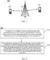
- FIG. 1 shows a wireless communication system 100 applied in an implementation of the present disclosure.
- the wireless communication system 100 may include a network device 110.
- the network device 100 may be a device that communicates with a terminal device.
- the network device 100 may provide communication coverage for a specific geographical area, and may communicate with a terminal device (e.g., UE) in the coverage area.
- the network device 100 may be a Base Transceiver Station (BTS) in a GSM system or CDMA system, a NodeB (NB) in a WCDMA system, an Evolutional Node B (eNB or eNodeB) in an LTE system, or a radio controller in a Cloud Radio Access Network (CRAN).
- BTS Base Transceiver Station
- NB NodeB
- eNB or eNodeB Evolutional Node B
- CRAN Cloud Radio Access Network
- the network device may be a relay station, an access point, an on-board device, or a wearable device, a network side device in
- the wireless communication system 100 also includes at least one terminal device 120 in the coverage area of the network device 110.
- the terminal device 120 may be mobile or fixed.
- the terminal device 120 may be referred to as an access terminal, User Equipment (UE), a subscriber unit, a subscriber station, a mobile station, a mobile platform, a remote station, a remote terminal, a mobile device, a user terminal, a terminal, a wireless communication device, a user agent, or a user apparatus.
- UE User Equipment
- the access terminal may be a cellular phone, a cordless phone, a Session Initiation Protocol (SIP) phone, a Wireless Local Loop (WLL) station, a Personal Digital Assistant (PDA), a handheld device with a wireless communication function, a computing device, or other processing device connected to a radio modem, an on-board device, a wearable device, a terminal device in a future 5G network, or a terminal device in a future evolved PLMN, or the like.
- SIP Session Initiation Protocol
- WLL Wireless Local Loop
- PDA Personal Digital Assistant
- the 5G system or network may also be referred to as a New Radio (NR) system or network.
- NR New Radio
- FIG. 1 exemplifies one network device and two terminal devices.
- the wireless communication system 100 may include multiple network devices, and another quantity of terminal devices may be included within the coverage area of each network device, which is not restricted in implementations of the present disclosure.
- the wireless communication system 100 may also include other network entities such as a network controller, a mobile management entity, and implementations of the present disclosure are not limited thereto.
- network entities such as a network controller, a mobile management entity, and implementations of the present disclosure are not limited thereto.
- system and “network” are often used interchangeably in this document.
- the term “and/or” in this document is merely an association relationship describing an associated object, indicating that there may be three relationships, for example, A and/or B may indicate three cases: A alone, A and B, and B alone.
- the symbol “/” in this document generally indicates that objects before and after the symbol "/" have an "or” relationship.
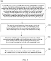
- FIG. 2 is a schematic flowchart of a wireless communication method 200 according to an implementation of the present disclosure.
- the method 200 may optionally be applied to the wireless communication system 100 described above.
- the method 200 includes the following contents.
- a terminal device determines multiple transmitting beams from transmitting beams of a network device, and determines a receiving beam matched with each transmitting beam of the multiple transmitting beams in at least two receiving beam groups of the terminal device.
- the transmitting beams of the network device may include beams transmitted through multiple transmitting nodes.
- different receiving beam groups correspond to different antenna panels of the terminal device.
- the terminal device measures downlink measurement signals transmitted by at least part of the transmitting beams of the network device by using at least part of receiving beams of each of the at least two receiving beam groups to obtain a measurement result; and determines the multiple transmitting beams and the receiving beam matched with the each transmitting beam of the multiple transmitting beams in the at least two receiving beam groups according to the measurement result.
- the terminal device randomly selects multiple transmitting beams from beams whose beam quality exceeds a threshold.
- the downlink measurement signal may be at least one of a synchronization signal, a channel state information reference signal, and a mobility related reference signal.
- the measurement result may be at least one of a Reference Signal Receiving Power (RSRP), a Reference Signal Receiving Quality (RSRQ), and a Signal to Interference plus Noise Ratio (SINR).
- RSRP Reference Signal Receiving Power
- RSRQ Reference Signal Receiving Quality
- SINR Signal to Interference plus Noise Ratio
- the receiving beam matched with the transmitting beam may refer to a receiving beam with the best signal quality for receiving downlink signals transmitted by the transmitting beam through the matched receiving beam.
- the receiving beam matched with one transmitting beam may be multiple receiving beams, that is, a signal quality for receiving the downlink signals through the multiple receiving beams respectively is higher than that for receiving the downlink signals by other receiving beams in at least two receiving beam groups.
- the notification message further carries a measurement result of measuring, by the terminal device, a downlink measurement signal transmitted by the each transmitting beam by using the receiving beam matched with the each transmitting beam of the multiple transmitting beams, so that the network device may select the transmitting beams according to the measurement result.
- the transmitting beam and one receiving beam matched with the transmitting beam may be referred to as a beam pair.
- the terminal device transmits a notification message to the network device, wherein the notification message is used for indicating the multiple transmitting beams and a receiving beam matched with the each transmitting beam, and includes information to be used by the network device for distinguishing a receiving beam group to which the receiving beam matched with the each transmitting beam belongs and distinguishing the receiving beam matched with the transmitting beam in the receiving beam group.
- the network device needs to learn a grouping situation of receiving beams matched with multiple transmitting beams selected by the terminal device and whether the receiving beams matched with multiple transmitting beams belong to the same receiving beam, then the terminal device may enable the network device to learn the information through the notification message.
- the notification message carries identification information of the receiving beam matched with the each transmitting beam
- the identification information of each receiving beam carried by the notification message is different from identification information of other receiving beams included in the at least two receiving beam groups, and the identification information of each receiving beam is to be used by the network device for distinguishing the receiving beam group to which the receiving beam matched with the each transmitting beam belongs and distinguishing the receiving beam matched with the transmitting beam in the receiving beam group.
- the notification message carries identification information of a receiving beam group to which the receiving beam matched with the each transmitting beam belongs, and identification information of the receiving beam matched with the each transmitting beam in the receiving beam group to which the receiving beam belongs, to be used by the network device for distinguishing the receiving beam group to which the receiving beam matched with the each transmitting beam belongs and distinguishing the receiving beam matched with the transmitting beam in the receiving beam group. Identification information of different receiving beams in the same receiving beam group is different.
- the reason that the network device needs to learn the grouping situation of receiving beams matched with the multiple transmitting beams selected by the terminal device and whether the receiving beams matched with multiple transmitting beams belong to the same receiving beam may be: different receiving beams of one receiving beam group of the terminal device cannot simultaneously receive downlink signals, the receiving beams of different receiving beam groups may simultaneously receive downlink signals, and the same receiving beam may simultaneously receive downlink signals transmitted by multiple transmitting beams.
- the received downlink signals may be downlink data signals, or downlink control signals, or the like.
- the terminal device may further report the grouping situation of the receiving beams matched with multiple transmitting beams selected by the terminal device and whether the receiving beams matched with multiple transmitting beams belong to the same receiving beam in other manners.
- the notification message reported by the terminal device may indicate that at least two receiving beams may be combined to correspond to one transmitting beam (that is, the at least two receiving beams belong to different receiving beam groups), and one receiving beam may correspond to multiple transmitting beams.
- multiple transmitting beams selected by the terminal device include multiple first transmitting beams.
- a receiving beam matched with the multiple first transmitting beams is a first receiving beam; and the first receiving beam is one receiving beam included in one of the at least two receiving beam groups.
- the terminal device may receive downlink signals transmitted simultaneously by the network device through the multiple first transmitting beams by using the first receiving beam.
- the terminal device may receive first indication information for indicating that the network device will simultaneously transmit the downlink signals to the terminal device by using the multiple first transmitting beams.
- the receiving beam matched with multiple transmitting beams is multiple receiving beams, and different receiving beams in the multiple receiving beams belong to different receiving beam groups.
- the terminal device may receive simultaneously downlink signals transmitted simultaneously by the network device through the multiple transmitting beams by using the multiple receiving beams.
- the terminal device may receive second indication information for indicating that the network device will simultaneously transmit the downlink signals to the terminal device by using the multiple transmitting beams.
- FIG. 3 is a schematic flowchart of a wireless communication method 300 according to an implementation of the present disclosure. As shown in FIG. 3 , the method 300 includes the following contents.
- a network device receives a notification message transmitted by a terminal device, wherein the notification message is used for indicating multiple transmitting beams used by the network device and a receiving beam matched with each transmitting beam of the multiple transmitting beams in at least two receiving beam groups of the terminal device, and the notification message includes information to be used by the network device for distinguishing a receiving beam group to which the receiving beam matched with the each transmitting beam belongs and distinguishing the receiving beam matched with the transmitting beam in the receiving beam group.
- the network device determines a beam group to which the receiving beam matched with the each transmitting beam belongs, and determines the receiving beam matched with the each transmitting beam according to the notification message.
- the notification message carries identification information of the receiving beam matched with the each transmitting beam, and the identification information of each receiving beam carried by the notification message is different from identification information of other receiving beams included in the at least two receiving beam groups.
- the network device may determine the beam group to which the receiving beam matched with the each transmitting beam belongs, and determine the receiving beam matched with the each transmitting beam according to the identification information of the receiving beam matched with the each transmitting beam and preset information.
- the preset information is used for indicating receiving beams included in the at least two receiving beam groups.
- the network device may determine multiple target transmitting beams from the multiple transmitting beams according to the beam group to which the receiving beam matched with the each transmitting beam belongs and the receiving beam matched with the each transmitting beam.
- the terminal device may report receiving beams included in each of the at least two receiving beam groups to the network device, so that the network device may preset information.
- the notification message carries identification information of the receiving beam group to which the receiving beam matched with the each transmitting beam belongs, and identification information of the receiving beam matched with the each transmitting beam in the receiving beam group to which the receiving beam belongs.
- the network device may determine the beam group to which the receiving beam matched with the each transmitting beam belongs and determine the receiving beam matched with the each transmitting beam according to the identification information of the receiving beam group to which the receiving beam matched with the each transmitting beam belongs and the identification information of the receiving beam matched with the each transmitting beam in the receiving beam group to which the receiving beam belongs; and determine at least one target receiving beam from the multiple transmitting beams according to the beam group to which the receiving beam matched with the each transmitting beam belongs and the receiving beam matched with the each transmitting beam.
- multiple target transmitting beams are determined from the multiple transmitting beams according to the beam group to which the receiving beam matched with the each transmitting beam belongs and the receiving beam matched with the each transmitting beam.
- the notification message further carries a measurement result of measuring, by the terminal device, a downlink measurement signal transmitted by the each transmitting beam by using the receiving beam matched with the each transmitting beam of the multiple transmitting beams.
- the network device further determines a target transmitting beam from multiple transmitting beams according to a congestion situation of the each transmitting beam, a data amount of downlink data to be transmitted, and a result for measuring the downlink measurement signal by a beam pair consisted of the each transmitting beam and the receiving beam matched with the each transmitting beam.
- the multiple target transmitting beams are matched with multiple receiving beams, and different receiving beams in the multiple receiving beams belong to different receiving beam groups, so that the network device transmits simultaneously downlink signals through the multiple target transmitting beams, and the terminal device may simultaneously receive downlink signals through the multiple receiving beams, thereby capable of achieving joint transmission.
- the multiple transmitting beams include multiple first transmitting beams.
- a receiving beam matched with the multiple first transmitting beams is a first receiving beam; and the first receiving beam is one receiving beam included in one of the at least two receiving beam groups. Therefore, the network device may simultaneously transmit downlink signals through the multiple first transmitting beams, and the terminal device may simultaneously receive downlink signals transmitted by the multiple first transmitting beams through the first receiving beam, thereby also capable of achieving joint transmission.
- the following implementation may exist, that is, multiple target transmitting beams are matched with multiple receiving beams, and at least two target transmitting beams are matched with one receiving beam.
- the network device transmits indication information to the terminal device, wherein the indication information is used for indicating that the network device will simultaneously transmit the downlink signals to the terminal device by using the multiple target transmitting beams.
- the network device simultaneously transmits downlink signals to the terminal device by using the multiple target transmitting beams, so that the terminal device may simultaneously receive the downlink signals transmitted by the network device through the multiple target transmitting beams.
- the terminal device indicates the selected multiple transmitting beams and the receiving beam matched with each transmitting beam in the multiple transmitting beams and includes information to be used by the network device for distinguishing a receiving beam group to which the receiving beam matched with the each transmitting beam belongs and distinguishing the receiving beam matched with the transmitting beam in the receiving beam group in the reported notification message.
- the network device may not only determine the receiving beam matched with the each transmitting beam, but also determine the receiving beam group to which the receiving beam matched with the each transmitting beam belongs according to the notification message, and further may select a more suitable transmitting beam for transmitting downlink signals to the terminal device in combination with the information of the receiving beam matched with the transmitting beam to obtain greater scheduling freedom.
- the problem of excessive overhead caused by reporting of any possible combination of receiving beams may be avoided by grouping the receiving beams.
- the network device may transmit downlink signals to the terminal device through a transmitting beam B1, a transmitting beam B2, and a transmitting beam B3 of a transmitting node 1, and may transmit downlink signals to the terminal device through a transmitting beam B4, a transmitting beam B5, and a transmitting beam B6 of a transmitting node 2.
- the terminal device may include two receiving beam groups, namely, a receiving beam group b1 and a receiving beam group b2, wherein the receiving beam group b1 may include receiving beams b1-1 and b1-2, and the receiving beam group b2 may include receiving beams b2-1 and b2-2.
- the network device may transmit downlink measurement signals to the terminal device through the transmitting beam B1, the transmitting beam B2, the transmitting beam B3, the transmitting beam B4, the transmitting beam B5, and the transmitting beam B6.
- the terminal device may measure the downlink signals transmitted by various transmitting beams to obtain a measurement result by using the receiving beams b1-1, b1-2, b2-1, and b2-2.
- the terminal device may select the transmitting beams according to the measurement result.
- the measurement result may be as follows, wherein, assuming the measurement result is RSRP, unlisted beam pairs may be considered as the beam pairs with particularly weak signals and may be ignored.
- multiple beam pairs may be selected from the above results, and the selected beam pairs and corresponding measurement results may be reported.
- a specific reporting manner may be as follows: [B1 b1-1 b1] - 60 dB [B2 b1-1 b1] - 70 dB [B5 b2-2 b2] - 65 dB [B6 b2-2 b2] - 75 dB
- B1 and b2 may be labels of the receiving beam groups, b1-1 and b1-2 may be a sub-label in the group b1 respectively, and b2-1 and b2-2 may be a sub-label in the group b2 respectively.
- labels of different receiving beams in a group are different, and labels of receiving beams in different groups may be the same.
- the network device may learn the receiving beam matched with the transmitting beam and the beam group to which the matched receiving beam belongs, that is, the network device may determine whether the receiving beams matched with multiple transmitting beams belong to the same receiving beam, and when it is determined that they do not belong to the same receiving beam, determine whether they belong to the same receiving beam group.
- the receiving beams matched with the transmitting beams selected by the terminal device may belong to different receiving beam groups.
- the network device may learn that the receiving beams matched with the transmitting beam B1 and the transmitting beam B6 belong to different receiving beam groups, and then may select B1 and B6 to simultaneously transmit downlink signals to the terminal device.
- the network device may learn that the receiving beams matched with the transmitting beam B2 and the transmitting beam B5 belong to different receiving beam groups, and then may select the transmitting beams B2 and B5 to simultaneously transmit downlink signals to the terminal device.
- the network device may learn that the receiving beams matched with the transmitting beam B2 and the transmitting beam B6 belong to different receiving beam groups, and then may select the transmitting beams B2 and B6 to simultaneously transmit downlink signals to the terminal device.
- the receiving beams matched with at least two transmitting beams selected by the terminal device may be the same receiving beam of the same receiving beam group.
- the network device may learn that the receiving beams matched with the transmitting beam B1 and the transmitting beam B2 belong to the same receiving beam of the same receiving beam group, and then may select B1 and B2 to simultaneously transmit downlink signals to the terminal device.
- the network device may learn that the receiving beams matched with the transmitting beam B5 and the transmitting beam B6 belong to the same receiving beam of the same receiving beam group, and then may select B5 and B6 to simultaneously transmit downlink signals to the terminal device.
- the network device may preset receiving beams included in each receiving beam group.
- the specific reporting manner may be as follows: [B1 b1-1] - 60 dB [B2 b1-1] - 70 dB [B5 b2-2] - 65 dB [B6 b2-2] - 75 dB
- Identification information of b1-1, b 1-2, b2-1, and b2-2 is different from each other.
- the network device may learn the receiving beams matched with the transmitting beams and the beam groups to which the matched receiving beams belong, that is, the network device may determine whether the receiving beams matched with multiple transmitting beams belong to the same receiving beam, and when it is determined that they do not belong to the same receiving beam, determine whether they belong to the same receiving beam group.
- the receiving beams matched with the transmitting beams selected by the terminal device may belong to different receiving beam groups.
- the network device may learn that the receiving beams matched with the transmitting beam B1 and the transmitting beam B6 belong to different beam groups, and then may select B1 and B6 to simultaneously transmit downlink signals to the terminal device.
- the network device may learn that the receiving beams matched with the transmitting beam B2 and the transmitting beam B5 belong to different beam groups, and then may select the transmitting beams B2 and B5 to simultaneously transmit downlink signals to the terminal device.
- the network device may learn that the receiving beams matched with the transmitting beam B2 and the transmitting beam B6 belong to different beam groups, and then may select the transmitting beams B2 and B6 to simultaneously transmit downlink signals to the terminal device.
- the receiving beams matched with transmitting beams selected by the terminal device may be the same receiving beam of the same receiving beam group.
- the network device may learn that the receiving beams matched with the transmitting beam B1 and the transmitting beam B2 belong to the same receiving beam of the same receiving beam group, and then may select B1 and B2 to simultaneously transmit downlink signals to the terminal device.
- the network device may learn that the receiving beams matched with the transmitting beam B5 and the transmitting beam B6 belong to the same receiving beam of the same receiving beam group, and then may select B5 and B6 to simultaneously transmit downlink signals to the terminal device.
- the terminal device indicates the selected multiple transmitting beams and the receiving beam matched with each transmitting beam in the multiple transmitting beams and includes information to be used by the network device for distinguishing a receiving beam group to which the receiving beam matched with the each transmitting beam belongs and distinguishing the receiving beam matched with the transmitting beam in the receiving beam group in the reported notification message.
- the network device may not only determine the receiving beam matched with the each transmitting beam, but also determine the receiving beam group to which the receiving beam matched with the each transmitting beam belongs according to the notification message, and further may select a more suitable transmitting beam for transmitting downlink signals to the terminal device in combination with the information of the receiving beam matched with the transmitting beam to obtain a greater scheduling freedom.
- the problem of excessive overhead caused by reporting of any possible combination of receiving beams may be avoided by grouping the receiving beams.
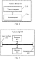
- FIG. 5 is a schematic block diagram of a terminal device 400 according to an implementation of the present disclosure. As shown in FIG. 5 , the terminal device 400 includes a processing unit 410 and a transceiving unit 420.
- the processing unit 410 is used for determining multiple transmitting beams from transmitting beams of a network device, and determining a receiving beam matched with each transmitting beam of the multiple transmitting beams in at least two receiving beam groups of the terminal device.
- the transceiving unit 420 is used for transmitting a notification message to the network device, wherein the notification message is used for indicating multiple transmitting beams and the receiving beam matched with the each transmitting beam, and includes information to be used by the network device for distinguishing a receiving beam group to which the receiving beam matched with the each transmitting beam belongs and distinguishing the receiving beam matched with the transmitting beam in the receiving beam group.
- different receiving beam groups correspond to different antenna panels of the terminal device.
- the notification message carries identification information of the receiving beam matched with the each transmitting beam
- the identification information of each receiving beam carried by the notification message is different from identification information of other receiving beams included in the at least two receiving beam groups, to be used by the network device for distinguishing the receiving beam group to which the receiving beam matched with the each transmitting beam belongs and distinguishing the receiving beam matched with the transmitting beam in the receiving beam group.
- the notification message carries identification information of the receiving beam group to which the receiving beam matched with the each transmitting beam belongs, and identification information of the receiving beam matched with the each transmitting beam in the receiving beam group to which the receiving beam belongs, to be used by the network device for distinguishing the receiving beam group to which the receiving beam matched with the each transmitting beam belongs and distinguishing the receiving beam matched with the transmitting beam in the receiving beam group.
- multiple transmitting beams includes multiple first transmitting beams, a receiving beam matched by the multiple first transmitting beams is a first receiving beam, and the first receiving beam is one receiving beam included in one of the at least two receiving beam groups.
- the transceiving unit 420 is further used for: receiving downlink signals simultaneously transmitted by the network device through the multiple first transmitting beams, by using the first receiving beam.
- the transceiving unit 420 is further used for: receiving first indication information, wherein the first indication information is used for indicating that the network device will simultaneously transmit the downlink signals to the terminal device by using the multiple first transmitting beams.
- the receiving beams matched with the multiple transmitting beams are multiple receiving beams, and different receiving beams in the multiple receiving beams belong to different receiving beam groups.
- the transceiving unit 420 is further used for: receiving simultaneously downlink signals simultaneously transmitted by the network device through the multiple transmitting beams, by using the multiple receiving beams.
- the transceiving unit 420 is further used for: receiving second indication information, wherein the second indication information is used for indicating that the network device will simultaneously transmit the downlink signals to the terminal device by using the multiple transmitting beams.
- the processing unit 410 is further used for: measuring downlink signals transmitted by at least part of the transmitting beams of the network device by using at least part of receiving beams of each of the at least two receiving beam groups to obtain a measurement result; and determining the multiple transmitting beams and the receiving beam matched with the each transmitting beam of the multiple transmitting beams in the at least two receiving beam groups according to the measurement result.
- the notification message further carries a measurement result of measuring, by the terminal device, a downlink measurement signal transmitted by the each transmitting beam by using the receiving beam matched with the each transmitting beam of the multiple transmitting beams.
- terminal device 400 may correspond to the terminal device in the method 200, and may implement corresponding functions implemented the terminal device in the method 200. For the sake of brevity, those will not be repeated here.
- FIG. 6 is a schematic block diagram of a network device 500 according to an implementation of the present disclosure. As shown in FIG. 6 , the network device 500 includes a transceiving unit 510 and a processing unit 520.
- the transceiving unit 510 is used for receiving a notification message transmitted by a terminal device, wherein the notification message is used for indicating multiple transmitting beams of the network device and a receiving beam matched with each transmitting beam of the multiple transmitting beams in at least two receiving beam groups of the terminal device, and the notification message includes information to be used by the network device for distinguishing a receiving beam group to which the receiving beam matched with the each transmitting beam belongs and distinguishing the receiving beam matched with the transmitting beam in the receiving beam group.
- the processing unit 520 is used for determining the receiving beam matched with the each transmitting beam and determining the beam group to which the receiving beam matched with the each transmitting beam belongs according to the notification message; and determining multiple target transmitting beams from the multiple transmitting beams according to the receiving beam matched with the each transmitting beam and the beam group to which the receiving beam matched with the each transmitting beam belong.
- the transceiving unit 510 is further used for transmitting simultaneously downlink signals to the terminal device by using the multiple target transmitting beams.
- different receiving beam groups of the terminal device correspond to different antenna panels of the terminal device.
- the notification message carries identification information of the receiving beam matched with the each transmitting beam, and the identification information of each receiving beam carried by the notification message is different from identification information of other receiving beams included in the at least two receiving beam groups.
- the processing unit 520 is further used for: determining the receiving beam matched with the each transmitting beam and determining the beam group to which the receiving beam matched with the each transmitting beam belongs according to the identification information of the receiving beam matched with the each transmitting beam and preset information, wherein the preset information is used for indicating receiving beams included in the at least two receiving beam groups.
- the notification message carries identification information of the receiving beam group to which the receiving beam matched with the each transmitting beam belongs, and identification information of the receiving beam matched with the each transmitting beam in the receiving beam group to which the receiving beam belongs.
- the processing unit 520 is further used for: determining the receiving beam matched with the each transmitting beam and determining the beam group to which the receiving beam matched with the each transmitting beam belongs according to the identification information of the receiving beam group to which the receiving beam matched with the each transmitting beam belongs and the identification information of the receiving beam matched with the each transmitting beam in the receiving beam group to which the receiving beam belongs.
- the multiple target transmitting beams are matched with multiple receiving beams, and different receiving beams in the multiple receiving beams belong to different receiving beam groups.
- the multiple transmitting beams include multiple first transmitting beams, a receiving beam matched with the multiple first transmitting beams is a first receiving beam, and the first receiving beam is one receiving beam included in one of the at least two receiving beam groups.
- the transceiving unit 510 is further used for: transmitting indication information to the terminal device, wherein the indication information is used for indicating that the network device will simultaneously transmit the downlink signals to the terminal device by using the multiple target transmitting beams.
- the notification message further carries a measurement result of measuring, by the terminal device, a downlink measurement signal transmitted by the each transmitting beam by using the receiving beam matched with the each transmitting beam of the multiple transmitting beams.
- the network device 500 may correspond to the network device in the method 300, and may implement corresponding functions implemented the network device in the method 300. For the sake of brevity, those will not be repeated here.
- FIG. 7 is a schematic structural diagram of a system chip 600 according to an implementation of the present disclosure.
- the system chip 600 of FIG. 7 includes an input interface 601, an output interface 602, a processor 603, and a memory 604.
- the input interface 601, the output interface 602, the processor 603, and the memory 604 are connected through internal communication connection lines.
- the processor 603 is used for executing codes in the memory 604.
- the processor 603 implements the method implemented by the terminal device in the method 200 shown in FIG. 2 .
- the processor 603 implements the method implemented by the terminal device in the method 200 shown in FIG. 2 .
- the processor 603 implements the method implemented by the terminal device in the method 200 shown in FIG. 2 .
- the processor 603 implements the method implemented by the network device in the method 300 shown in FIG. 3 .
- the processor 603 implements the method implemented by the network device in the method 300 shown in FIG. 3 .
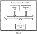
- FIG. 8 is a schematic block diagram of a communication device 700 according to an implementation of the present disclosure.
- the communication device 700 includes a processor 710 and a memory 720.
- the memory 720 may store program codes, and the processor 710 may execute the program codes stored in the memory 720.
- the communication device 700 may include a transceiver 730, and the processor 710 may control the transceiver 730 to communicate externally.
- the processor 710 may invoke the program codes stored in the memory 720 to perform corresponding operations of the terminal device in the method 200 shown in FIG. 2 , which will not be described here repeatedly for brevity.
- the processor 710 may invoke the program codes stored in the memory 720 to perform corresponding operations of the network device in the method 300 shown in FIG. 3 , which will not be described here repeatedly for brevity.
- the units described as separated components may or may not be physically separated, and the component shown as a unit may or may not be a physical unit, i.e., it may be located in one place or may be allocated over multiple network units. Some or all of the units may be selected according to practical needs to achieve a purpose of the implementations.
- various functional units in various implementations of the present disclosure may be integrated in one processing unit, or various units may be physically present separately, or two or more units may be integrated in one unit.
- the function may be stored in a computer readable storage medium if implemented in a form of software functional unit and sold or used as a separate product.
- the technical solutions of the implementations of the present disclosure in essence, or the part contributing to the related art, or the part of the technical solution, may be embodied in the form of a software product stored in a storage medium, including several instructions for causing a computer device (which may be a personal computer, a server, or a network device, etc.) to perform all or part of the acts of the methods described in various implementations of the present disclosure.
- the aforementioned storage medium include U disk, mobile hard disk, read-only memory (ROM), random access memory (RAM), magnetic disk or optical disk, and other medium capable of storing program codes.
Landscapes
- Engineering & Computer Science (AREA)
- Computer Networks & Wireless Communication (AREA)
- Signal Processing (AREA)
- Mobile Radio Communication Systems (AREA)
Description
- The present disclosure relates to the field of communication, and more particularly to a wireless communication method, a terminal device, and a network device.
- In a multi-beam system, a network device may use multiple transmitting beams to transmit downlink signals to a terminal device, and the terminal device may use matched receiving beams to receive the downlink signals transmitted by the multiple transmitting beams.
- However, matched beams of different downlink transmitting beams of the network device may correspond to different receiving beams of the terminal device, and the network device needs to learn matched receiving beams of the downlink transmitting beams to better select transmitting beams for transmitting signals to the terminal device.
- How the network device learns information of receiving beams matched with downlink transmitting beams and then selects appropriate transmitting beams is an urgent problem to be solved.
- Related technologies are known from
US 2013/0223251 A1 . - Implementations of the present disclosure provide a wireless communication method, a terminal device, and a network device according to appended independent claims. Further improvements and embodiments are provided in the dependent claims.
- The invention is defined by the
independent claims 1, 9, 14, 22. Preferred embodiments of the invention are stipulated in the dependent claims. While several embodiments and/or examples have been disclosed in the description, the subject matter for which protection is sought is strictly and solely limited to those embodiments and/or examples encompassed by the scope of the appended claims. Embodiments and/or examples mentioned in the description that do not fall under the scope of the claims are useful for understanding the invention. - To describe technical solutions of implementations of the present disclosure more clearly, accompanying drawings that need to be used in the implementations or description for the prior art will be briefly introduced below. It is apparent that the accompanying drawings described below are only some implementations of the present disclosure; and for a person of ordinary skill in the art, other drawings may be obtained according to these drawings without paying an inventive effort.
-
FIG. 1 is a schematic diagram of a wireless communication system according to an implementation of the present disclosure. -
FIG. 2 is a schematic flowchart of a wireless communication method according to an implementation of the present disclosure. -
FIG. 3 is a schematic flowchart of a wireless communication method according to an implementation of the present disclosure. -
FIG. 4 is a schematic diagram of matching between transmitting beams and receiving beams according to an implementation of the present disclosure. -
FIG. 5 is a schematic block diagram of a terminal device according to an implementation of the present disclosure. -
FIG. 6 is a schematic block diagram of a network device according to an implementation of the present disclosure. -
FIG. 7 is a schematic diagram of a system chip according to an implementation of the present disclosure. -
FIG. 8 is a schematic block diagram of a communication device according to an implementation of the present disclosure. - The technical solutions in the implementations of the present disclosure will be described below with reference to the drawings in the implementations of the present disclosure. It is apparent that the implementations described are just some implementations of the present disclosure, but not all implementations of the present disclosure.
- The technical solutions of the implementations of the present disclosure may be applied to various communication systems, such as, a Global System of Mobile communication (GSM) system, a Code Division Multiple Access (CDMA) system, a Wideband Code Division Multiple Access (WCDMA) system, a General Packet Radio Service (GPRS) system, a Long Term Evolution (LTE) system, a LTE Frequency Division Duplex (FDD) system, a LTE Time Division Duplex (TDD) system, a Universal Mobile Telecommunication System (UMTS), a Worldwide Interoperability for Microwave Access (WiMAX) communication system, or a future 5G system.
-
FIG. 1 shows awireless communication system 100 applied in an implementation of the present disclosure. Thewireless communication system 100 may include anetwork device 110. Thenetwork device 100 may be a device that communicates with a terminal device. Thenetwork device 100 may provide communication coverage for a specific geographical area, and may communicate with a terminal device (e.g., UE) in the coverage area. Optionally, thenetwork device 100 may be a Base Transceiver Station (BTS) in a GSM system or CDMA system, a NodeB (NB) in a WCDMA system, an Evolutional Node B (eNB or eNodeB) in an LTE system, or a radio controller in a Cloud Radio Access Network (CRAN). Or the network device may be a relay station, an access point, an on-board device, or a wearable device, a network side device in a future 5G network, or a network device in a future evolved Public Land Mobile Network (PLMN), etc. - The
wireless communication system 100 also includes at least oneterminal device 120 in the coverage area of thenetwork device 110. Theterminal device 120 may be mobile or fixed. Optionally, theterminal device 120 may be referred to as an access terminal, User Equipment (UE), a subscriber unit, a subscriber station, a mobile station, a mobile platform, a remote station, a remote terminal, a mobile device, a user terminal, a terminal, a wireless communication device, a user agent, or a user apparatus. The access terminal may be a cellular phone, a cordless phone, a Session Initiation Protocol (SIP) phone, a Wireless Local Loop (WLL) station, a Personal Digital Assistant (PDA), a handheld device with a wireless communication function, a computing device, or other processing device connected to a radio modem, an on-board device, a wearable device, a terminal device in a future 5G network, or a terminal device in a future evolved PLMN, or the like. - Optionally, the 5G system or network may also be referred to as a New Radio (NR) system or network.
-
FIG. 1 exemplifies one network device and two terminal devices. Optionally, thewireless communication system 100 may include multiple network devices, and another quantity of terminal devices may be included within the coverage area of each network device, which is not restricted in implementations of the present disclosure. - Optionally, the
wireless communication system 100 may also include other network entities such as a network controller, a mobile management entity, and implementations of the present disclosure are not limited thereto. - It should be understood that the terms "system" and "network" are often used interchangeably in this document. The term "and/or" in this document is merely an association relationship describing an associated object, indicating that there may be three relationships, for example, A and/or B may indicate three cases: A alone, A and B, and B alone. In addition, the symbol "/" in this document generally indicates that objects before and after the symbol "/" have an "or" relationship.
-
FIG. 2 is a schematic flowchart of awireless communication method 200 according to an implementation of the present disclosure. Themethod 200 may optionally be applied to thewireless communication system 100 described above. - As shown in
FIG. 2 , themethod 200 includes the following contents. - In 210, a terminal device determines multiple transmitting beams from transmitting beams of a network device, and determines a receiving beam matched with each transmitting beam of the multiple transmitting beams in at least two receiving beam groups of the terminal device.
- Optionally, the transmitting beams of the network device may include beams transmitted through multiple transmitting nodes.
- Optionally, in the at least two receiving beam groups, different receiving beam groups correspond to different antenna panels of the terminal device.
- The terminal device measures downlink measurement signals transmitted by at least part of the transmitting beams of the network device by using at least part of receiving beams of each of the at least two receiving beam groups to obtain a measurement result; and determines the multiple transmitting beams and the receiving beam matched with the each transmitting beam of the multiple transmitting beams in the at least two receiving beam groups according to the measurement result.
- Specifically, the terminal device randomly selects multiple transmitting beams from beams whose beam quality exceeds a threshold.
- Optionally, the downlink measurement signal may be at least one of a synchronization signal, a channel state information reference signal, and a mobility related reference signal.
- Optionally, the measurement result may be at least one of a Reference Signal Receiving Power (RSRP), a Reference Signal Receiving Quality (RSRQ), and a Signal to Interference plus Noise Ratio (SINR).
- Optionally, the receiving beam matched with the transmitting beam may refer to a receiving beam with the best signal quality for receiving downlink signals transmitted by the transmitting beam through the matched receiving beam.
- Optionally, the receiving beam matched with one transmitting beam may be multiple receiving beams, that is, a signal quality for receiving the downlink signals through the multiple receiving beams respectively is higher than that for receiving the downlink signals by other receiving beams in at least two receiving beam groups.
- Optionally, the notification message further carries a measurement result of measuring, by the terminal device, a downlink measurement signal transmitted by the each transmitting beam by using the receiving beam matched with the each transmitting beam of the multiple transmitting beams, so that the network device may select the transmitting beams according to the measurement result.
- Optionally, in the implementation of the present disclosure, the transmitting beam and one receiving beam matched with the transmitting beam may be referred to as a beam pair.
- In 220, the terminal device transmits a notification message to the network device, wherein the notification message is used for indicating the multiple transmitting beams and a receiving beam matched with the each transmitting beam, and includes information to be used by the network device for distinguishing a receiving beam group to which the receiving beam matched with the each transmitting beam belongs and distinguishing the receiving beam matched with the transmitting beam in the receiving beam group.
- Optionally, the network device needs to learn a grouping situation of receiving beams matched with multiple transmitting beams selected by the terminal device and whether the receiving beams matched with multiple transmitting beams belong to the same receiving beam, then the terminal device may enable the network device to learn the information through the notification message.
- In one implementation, the notification message carries identification information of the receiving beam matched with the each transmitting beam, and the identification information of each receiving beam carried by the notification message is different from identification information of other receiving beams included in the at least two receiving beam groups, and the identification information of each receiving beam is to be used by the network device for distinguishing the receiving beam group to which the receiving beam matched with the each transmitting beam belongs and distinguishing the receiving beam matched with the transmitting beam in the receiving beam group.
- In another implementation, the notification message carries identification information of a receiving beam group to which the receiving beam matched with the each transmitting beam belongs, and identification information of the receiving beam matched with the each transmitting beam in the receiving beam group to which the receiving beam belongs, to be used by the network device for distinguishing the receiving beam group to which the receiving beam matched with the each transmitting beam belongs and distinguishing the receiving beam matched with the transmitting beam in the receiving beam group. Identification information of different receiving beams in the same receiving beam group is different.
- Optionally, the reason that the network device needs to learn the grouping situation of receiving beams matched with the multiple transmitting beams selected by the terminal device and whether the receiving beams matched with multiple transmitting beams belong to the same receiving beam may be: different receiving beams of one receiving beam group of the terminal device cannot simultaneously receive downlink signals, the receiving beams of different receiving beam groups may simultaneously receive downlink signals, and the same receiving beam may simultaneously receive downlink signals transmitted by multiple transmitting beams. Herein, the received downlink signals may be downlink data signals, or downlink control signals, or the like.
- Optionally, in the implementation of the present disclosure, in addition to the above two implementations, the terminal device may further report the grouping situation of the receiving beams matched with multiple transmitting beams selected by the terminal device and whether the receiving beams matched with multiple transmitting beams belong to the same receiving beam in other manners.
- For example, the notification message reported by the terminal device may indicate that at least two receiving beams may be combined to correspond to one transmitting beam (that is, the at least two receiving beams belong to different receiving beam groups), and one receiving beam may correspond to multiple transmitting beams.
- Optionally, multiple transmitting beams selected by the terminal device include multiple first transmitting beams. Herein, a receiving beam matched with the multiple first transmitting beams is a first receiving beam; and the first receiving beam is one receiving beam included in one of the at least two receiving beam groups. The terminal device may receive downlink signals transmitted simultaneously by the network device through the multiple first transmitting beams by using the first receiving beam.
- Optionally, before the terminal device receives the downlink signals transmitted simultaneously by the network device through the multiple first transmitting beams by using the first receiving beam, the terminal device may receive first indication information for indicating that the network device will simultaneously transmit the downlink signals to the terminal device by using the multiple first transmitting beams.
- Optionally, the receiving beam matched with multiple transmitting beams is multiple receiving beams, and different receiving beams in the multiple receiving beams belong to different receiving beam groups. The terminal device may receive simultaneously downlink signals transmitted simultaneously by the network device through the multiple transmitting beams by using the multiple receiving beams.
- Optionally, before the terminal device receives simultaneously downlink signals transmitted simultaneously by the network device through the multiple transmitting beams by using the multiple receiving beams, the terminal device may receive second indication information for indicating that the network device will simultaneously transmit the downlink signals to the terminal device by using the multiple transmitting beams.
-
FIG. 3 is a schematic flowchart of awireless communication method 300 according to an implementation of the present disclosure. As shown inFIG. 3 , themethod 300 includes the following contents. - In 310, a network device receives a notification message transmitted by a terminal device, wherein the notification message is used for indicating multiple transmitting beams used by the network device and a receiving beam matched with each transmitting beam of the multiple transmitting beams in at least two receiving beam groups of the terminal device, and the notification message includes information to be used by the network device for distinguishing a receiving beam group to which the receiving beam matched with the each transmitting beam belongs and distinguishing the receiving beam matched with the transmitting beam in the receiving beam group.
- In 320, the network device determines a beam group to which the receiving beam matched with the each transmitting beam belongs, and determines the receiving beam matched with the each transmitting beam according to the notification message.
- Optionally, the notification message carries identification information of the receiving beam matched with the each transmitting beam, and the identification information of each receiving beam carried by the notification message is different from identification information of other receiving beams included in the at least two receiving beam groups.
- Then, the network device may determine the beam group to which the receiving beam matched with the each transmitting beam belongs, and determine the receiving beam matched with the each transmitting beam according to the identification information of the receiving beam matched with the each transmitting beam and preset information. Herein the preset information is used for indicating receiving beams included in the at least two receiving beam groups. The network device may determine multiple target transmitting beams from the multiple transmitting beams according to the beam group to which the receiving beam matched with the each transmitting beam belongs and the receiving beam matched with the each transmitting beam.
- Optionally, the terminal device may report receiving beams included in each of the at least two receiving beam groups to the network device, so that the network device may preset information.
- Optionally, the notification message carries identification information of the receiving beam group to which the receiving beam matched with the each transmitting beam belongs, and identification information of the receiving beam matched with the each transmitting beam in the receiving beam group to which the receiving beam belongs.
- Then, the network device may determine the beam group to which the receiving beam matched with the each transmitting beam belongs and determine the receiving beam matched with the each transmitting beam according to the identification information of the receiving beam group to which the receiving beam matched with the each transmitting beam belongs and the identification information of the receiving beam matched with the each transmitting beam in the receiving beam group to which the receiving beam belongs; and determine at least one target receiving beam from the multiple transmitting beams according to the beam group to which the receiving beam matched with the each transmitting beam belongs and the receiving beam matched with the each transmitting beam.
- In 330, multiple target transmitting beams are determined from the multiple transmitting beams according to the beam group to which the receiving beam matched with the each transmitting beam belongs and the receiving beam matched with the each transmitting beam.
- The notification message further carries a measurement result of measuring, by the terminal device, a downlink measurement signal transmitted by the each transmitting beam by using the receiving beam matched with the each transmitting beam of the multiple transmitting beams.
- The network device further determines a target transmitting beam from multiple transmitting beams according to a congestion situation of the each transmitting beam, a data amount of downlink data to be transmitted, and a result for measuring the downlink measurement signal by a beam pair consisted of the each transmitting beam and the receiving beam matched with the each transmitting beam.
- Optionally, the multiple target transmitting beams are matched with multiple receiving beams, and different receiving beams in the multiple receiving beams belong to different receiving beam groups, so that the network device transmits simultaneously downlink signals through the multiple target transmitting beams, and the terminal device may simultaneously receive downlink signals through the multiple receiving beams, thereby capable of achieving joint transmission.
- Optionally, the multiple transmitting beams include multiple first transmitting beams. Herein, a receiving beam matched with the multiple first transmitting beams is a first receiving beam; and the first receiving beam is one receiving beam included in one of the at least two receiving beam groups. Therefore, the network device may simultaneously transmit downlink signals through the multiple first transmitting beams, and the terminal device may simultaneously receive downlink signals transmitted by the multiple first transmitting beams through the first receiving beam, thereby also capable of achieving joint transmission.
- Optionally, in the implementation of the present disclosure, the following implementation may exist, that is, multiple target transmitting beams are matched with multiple receiving beams, and at least two target transmitting beams are matched with one receiving beam.
- Optionally, in the implementation of the present disclosure, the network device transmits indication information to the terminal device, wherein the indication information is used for indicating that the network device will simultaneously transmit the downlink signals to the terminal device by using the multiple target transmitting beams.
- In 340, the network device simultaneously transmits downlink signals to the terminal device by using the multiple target transmitting beams, so that the terminal device may simultaneously receive the downlink signals transmitted by the network device through the multiple target transmitting beams.
- Therefore, in the implementation of the present disclosure, the terminal device indicates the selected multiple transmitting beams and the receiving beam matched with each transmitting beam in the multiple transmitting beams and includes information to be used by the network device for distinguishing a receiving beam group to which the receiving beam matched with the each transmitting beam belongs and distinguishing the receiving beam matched with the transmitting beam in the receiving beam group in the reported notification message. Thus, the network device may not only determine the receiving beam matched with the each transmitting beam, but also determine the receiving beam group to which the receiving beam matched with the each transmitting beam belongs according to the notification message, and further may select a more suitable transmitting beam for transmitting downlink signals to the terminal device in combination with the information of the receiving beam matched with the transmitting beam to obtain greater scheduling freedom. The problem of excessive overhead caused by reporting of any possible combination of receiving beams may be avoided by grouping the receiving beams.
- To understand the present disclosure more clearly, the wireless communication method according to the implementation of the present disclosure will be described below in combination with
FIG. 4 . - The network device may transmit downlink signals to the terminal device through a transmitting beam B1, a transmitting beam B2, and a transmitting beam B3 of a transmitting
node 1, and may transmit downlink signals to the terminal device through a transmitting beam B4, a transmitting beam B5, and a transmitting beam B6 of a transmittingnode 2. The terminal device may include two receiving beam groups, namely, a receiving beam group b1 and a receiving beam group b2, wherein the receiving beam group b1 may include receiving beams b1-1 and b1-2, and the receiving beam group b2 may include receiving beams b2-1 and b2-2. - The network device may transmit downlink measurement signals to the terminal device through the transmitting beam B1, the transmitting beam B2, the transmitting beam B3, the transmitting beam B4, the transmitting beam B5, and the transmitting beam B6. The terminal device may measure the downlink signals transmitted by various transmitting beams to obtain a measurement result by using the receiving beams b1-1, b1-2, b2-1, and b2-2. The terminal device may select the transmitting beams according to the measurement result.
- For example, the measurement result may be as follows, wherein, assuming the measurement result is RSRP, unlisted beam pairs may be considered as the beam pairs with particularly weak signals and may be ignored.
[B1 b1-1] - 60 dB [B1 b1-2] - 120 dB [B2 b1-1] - 70 dB [B2 b1-2] - 120 dB [B3 b1-1] - 100 dB [B3 b1-2] - 120 dB [B4 b2-1] - 120 dB [B4 b2-2] - 100 dB [B5 b2-1] - 120 dB [B5 b2-2] - 65 dB [B6 b2-1] - 120 dB [B6 b2-2] - 75 dB - If four transmitting beams will be reported, multiple beam pairs may be selected from the above results, and the selected beam pairs and corresponding measurement results may be reported.
- Two specific reporting manners will be described below, but it should be understood that the implementations of the present disclosure are not limited thereto.
- In one implementation, a specific reporting manner may be as follows:
[B1 b1-1 b1] - 60 dB [B2 b1-1 b1] - 70 dB [B5 b2-2 b2] - 65 dB [B6 b2-2 b2] - 75 dB - B1 and b2 may be labels of the receiving beam groups, b1-1 and b1-2 may be a sub-label in the group b1 respectively, and b2-1 and b2-2 may be a sub-label in the group b2 respectively. Herein labels of different receiving beams in a group are different, and labels of receiving beams in different groups may be the same.
- If the network device receives the above measurement report, the network device may learn the receiving beam matched with the transmitting beam and the beam group to which the matched receiving beam belongs, that is, the network device may determine whether the receiving beams matched with multiple transmitting beams belong to the same receiving beam, and when it is determined that they do not belong to the same receiving beam, determine whether they belong to the same receiving beam group.
- Herein, the receiving beams matched with the transmitting beams selected by the terminal device may belong to different receiving beam groups.
- For example, the network device may learn that the receiving beams matched with the transmitting beam B1 and the transmitting beam B6 belong to different receiving beam groups, and then may select B1 and B6 to simultaneously transmit downlink signals to the terminal device.
- Or, the network device may learn that the receiving beams matched with the transmitting beam B2 and the transmitting beam B5 belong to different receiving beam groups, and then may select the transmitting beams B2 and B5 to simultaneously transmit downlink signals to the terminal device.
- Or, the network device may learn that the receiving beams matched with the transmitting beam B2 and the transmitting beam B6 belong to different receiving beam groups, and then may select the transmitting beams B2 and B6 to simultaneously transmit downlink signals to the terminal device.
- Herein, the receiving beams matched with at least two transmitting beams selected by the terminal device may be the same receiving beam of the same receiving beam group.
- For example, the network device may learn that the receiving beams matched with the transmitting beam B1 and the transmitting beam B2 belong to the same receiving beam of the same receiving beam group, and then may select B1 and B2 to simultaneously transmit downlink signals to the terminal device.
- For example, the network device may learn that the receiving beams matched with the transmitting beam B5 and the transmitting beam B6 belong to the same receiving beam of the same receiving beam group, and then may select B5 and B6 to simultaneously transmit downlink signals to the terminal device.
- In another implementation, the network device may preset receiving beams included in each receiving beam group. The specific reporting manner may be as follows:
[B1 b1-1] - 60 dB [B2 b1-1] - 70 dB [B5 b2-2] - 65 dB [B6 b2-2] - 75 dB - Identification information of b1-1, b 1-2, b2-1, and b2-2 is different from each other.
- If the network device receives the above measurement report, in combination with the preset information, the network device may learn the receiving beams matched with the transmitting beams and the beam groups to which the matched receiving beams belong, that is, the network device may determine whether the receiving beams matched with multiple transmitting beams belong to the same receiving beam, and when it is determined that they do not belong to the same receiving beam, determine whether they belong to the same receiving beam group.
- Herein, the receiving beams matched with the transmitting beams selected by the terminal device may belong to different receiving beam groups.
- For example, the network device may learn that the receiving beams matched with the transmitting beam B1 and the transmitting beam B6 belong to different beam groups, and then may select B1 and B6 to simultaneously transmit downlink signals to the terminal device.
- Or, the network device may learn that the receiving beams matched with the transmitting beam B2 and the transmitting beam B5 belong to different beam groups, and then may select the transmitting beams B2 and B5 to simultaneously transmit downlink signals to the terminal device.
- Or, the network device may learn that the receiving beams matched with the transmitting beam B2 and the transmitting beam B6 belong to different beam groups, and then may select the transmitting beams B2 and B6 to simultaneously transmit downlink signals to the terminal device.
- Herein, the receiving beams matched with transmitting beams selected by the terminal device may be the same receiving beam of the same receiving beam group.
- For example, the network device may learn that the receiving beams matched with the transmitting beam B1 and the transmitting beam B2 belong to the same receiving beam of the same receiving beam group, and then may select B1 and B2 to simultaneously transmit downlink signals to the terminal device.
- For example, the network device may learn that the receiving beams matched with the transmitting beam B5 and the transmitting beam B6 belong to the same receiving beam of the same receiving beam group, and then may select B5 and B6 to simultaneously transmit downlink signals to the terminal device.
- Therefore, in the implementations of the present disclosure, the terminal device indicates the selected multiple transmitting beams and the receiving beam matched with each transmitting beam in the multiple transmitting beams and includes information to be used by the network device for distinguishing a receiving beam group to which the receiving beam matched with the each transmitting beam belongs and distinguishing the receiving beam matched with the transmitting beam in the receiving beam group in the reported notification message. Thus, the network device may not only determine the receiving beam matched with the each transmitting beam, but also determine the receiving beam group to which the receiving beam matched with the each transmitting beam belongs according to the notification message, and further may select a more suitable transmitting beam for transmitting downlink signals to the terminal device in combination with the information of the receiving beam matched with the transmitting beam to obtain a greater scheduling freedom. The problem of excessive overhead caused by reporting of any possible combination of receiving beams may be avoided by grouping the receiving beams.
-
FIG. 5 is a schematic block diagram of aterminal device 400 according to an implementation of the present disclosure. As shown inFIG. 5 , theterminal device 400 includes aprocessing unit 410 and atransceiving unit 420. - The
processing unit 410 is used for determining multiple transmitting beams from transmitting beams of a network device, and determining a receiving beam matched with each transmitting beam of the multiple transmitting beams in at least two receiving beam groups of the terminal device. - The
transceiving unit 420 is used for transmitting a notification message to the network device, wherein the notification message is used for indicating multiple transmitting beams and the receiving beam matched with the each transmitting beam, and includes information to be used by the network device for distinguishing a receiving beam group to which the receiving beam matched with the each transmitting beam belongs and distinguishing the receiving beam matched with the transmitting beam in the receiving beam group. - Optionally, in the at least two receiving beam groups, different receiving beam groups correspond to different antenna panels of the terminal device.
- Optionally, the notification message carries identification information of the receiving beam matched with the each transmitting beam, and the identification information of each receiving beam carried by the notification message is different from identification information of other receiving beams included in the at least two receiving beam groups, to be used by the network device for distinguishing the receiving beam group to which the receiving beam matched with the each transmitting beam belongs and distinguishing the receiving beam matched with the transmitting beam in the receiving beam group.
- Optionally, the notification message carries identification information of the receiving beam group to which the receiving beam matched with the each transmitting beam belongs, and identification information of the receiving beam matched with the each transmitting beam in the receiving beam group to which the receiving beam belongs, to be used by the network device for distinguishing the receiving beam group to which the receiving beam matched with the each transmitting beam belongs and distinguishing the receiving beam matched with the transmitting beam in the receiving beam group.
- Optionally, multiple transmitting beams includes multiple first transmitting beams, a receiving beam matched by the multiple first transmitting beams is a first receiving beam, and the first receiving beam is one receiving beam included in one of the at least two receiving beam groups.
- The
transceiving unit 420 is further used for: receiving downlink signals simultaneously transmitted by the network device through the multiple first transmitting beams, by using the first receiving beam. - Optionally, the
transceiving unit 420 is further used for: receiving first indication information, wherein the first indication information is used for indicating that the network device will simultaneously transmit the downlink signals to the terminal device by using the multiple first transmitting beams. - Optionally, the receiving beams matched with the multiple transmitting beams are multiple receiving beams, and different receiving beams in the multiple receiving beams belong to different receiving beam groups.
- The
transceiving unit 420 is further used for: receiving simultaneously downlink signals simultaneously transmitted by the network device through the multiple transmitting beams, by using the multiple receiving beams. - Optionally, the
transceiving unit 420 is further used for: receiving second indication information, wherein the second indication information is used for indicating that the network device will simultaneously transmit the downlink signals to the terminal device by using the multiple transmitting beams. - The
processing unit 410 is further used for: measuring downlink signals transmitted by at least part of the transmitting beams of the network device by using at least part of receiving beams of each of the at least two receiving beam groups to obtain a measurement result; and determining the multiple transmitting beams and the receiving beam matched with the each transmitting beam of the multiple transmitting beams in the at least two receiving beam groups according to the measurement result. - Optionally, the notification message further carries a measurement result of measuring, by the terminal device, a downlink measurement signal transmitted by the each transmitting beam by using the receiving beam matched with the each transmitting beam of the multiple transmitting beams.
- It should be understood that the
terminal device 400 may correspond to the terminal device in themethod 200, and may implement corresponding functions implemented the terminal device in themethod 200. For the sake of brevity, those will not be repeated here. -
FIG. 6 is a schematic block diagram of anetwork device 500 according to an implementation of the present disclosure. As shown inFIG. 6 , thenetwork device 500 includes atransceiving unit 510 and aprocessing unit 520. - The
transceiving unit 510 is used for receiving a notification message transmitted by a terminal device, wherein the notification message is used for indicating multiple transmitting beams of the network device and a receiving beam matched with each transmitting beam of the multiple transmitting beams in at least two receiving beam groups of the terminal device, and the notification message includes information to be used by the network device for distinguishing a receiving beam group to which the receiving beam matched with the each transmitting beam belongs and distinguishing the receiving beam matched with the transmitting beam in the receiving beam group. - The
processing unit 520 is used for determining the receiving beam matched with the each transmitting beam and determining the beam group to which the receiving beam matched with the each transmitting beam belongs according to the notification message; and determining multiple target transmitting beams from the multiple transmitting beams according to the receiving beam matched with the each transmitting beam and the beam group to which the receiving beam matched with the each transmitting beam belong. - The
transceiving unit 510 is further used for transmitting simultaneously downlink signals to the terminal device by using the multiple target transmitting beams. - Optionally, different receiving beam groups of the terminal device correspond to different antenna panels of the terminal device.
- Optionally, the notification message carries identification information of the receiving beam matched with the each transmitting beam, and the identification information of each receiving beam carried by the notification message is different from identification information of other receiving beams included in the at least two receiving beam groups.
- The
processing unit 520 is further used for: determining the receiving beam matched with the each transmitting beam and determining the beam group to which the receiving beam matched with the each transmitting beam belongs according to the identification information of the receiving beam matched with the each transmitting beam and preset information, wherein the preset information is used for indicating receiving beams included in the at least two receiving beam groups. - Optionally, the notification message carries identification information of the receiving beam group to which the receiving beam matched with the each transmitting beam belongs, and identification information of the receiving beam matched with the each transmitting beam in the receiving beam group to which the receiving beam belongs.
- The
processing unit 520 is further used for: determining the receiving beam matched with the each transmitting beam and determining the beam group to which the receiving beam matched with the each transmitting beam belongs according to the identification information of the receiving beam group to which the receiving beam matched with the each transmitting beam belongs and the identification information of the receiving beam matched with the each transmitting beam in the receiving beam group to which the receiving beam belongs. - Optionally, the multiple target transmitting beams are matched with multiple receiving beams, and different receiving beams in the multiple receiving beams belong to different receiving beam groups.
- Optionally, the multiple transmitting beams include multiple first transmitting beams, a receiving beam matched with the multiple first transmitting beams is a first receiving beam, and the first receiving beam is one receiving beam included in one of the at least two receiving beam groups.
- Optionally, the
transceiving unit 510 is further used for: transmitting indication information to the terminal device, wherein the indication information is used for indicating that the network device will simultaneously transmit the downlink signals to the terminal device by using the multiple target transmitting beams. - The notification message further carries a measurement result of measuring, by the terminal device, a downlink measurement signal transmitted by the each transmitting beam by using the receiving beam matched with the each transmitting beam of the multiple transmitting beams.
- It should be understood that the
network device 500 may correspond to the network device in themethod 300, and may implement corresponding functions implemented the network device in themethod 300. For the sake of brevity, those will not be repeated here. -
FIG. 7 is a schematic structural diagram of asystem chip 600 according to an implementation of the present disclosure. Thesystem chip 600 ofFIG. 7 includes aninput interface 601, anoutput interface 602, aprocessor 603, and amemory 604. Theinput interface 601, theoutput interface 602, theprocessor 603, and thememory 604 are connected through internal communication connection lines. Theprocessor 603 is used for executing codes in thememory 604. - Optionally, when the codes are executed, the
processor 603 implements the method implemented by the terminal device in themethod 200 shown inFIG. 2 . For sake of conciseness, it will not be repeated here. - Optionally, when the codes are executed, the
processor 603 implements the method implemented by the network device in themethod 300 shown inFIG. 3 . For sake of conciseness, it will not be repeated here. -
FIG. 8 is a schematic block diagram of acommunication device 700 according to an implementation of the present disclosure. As shown inFIG. 8 , thecommunication device 700 includes aprocessor 710 and amemory 720. Thememory 720 may store program codes, and theprocessor 710 may execute the program codes stored in thememory 720. - Optionally, as shown in
FIG. 8 , thecommunication device 700 may include atransceiver 730, and theprocessor 710 may control thetransceiver 730 to communicate externally. - Optionally, the
processor 710 may invoke the program codes stored in thememory 720 to perform corresponding operations of the terminal device in themethod 200 shown inFIG. 2 , which will not be described here repeatedly for brevity. - Optionally, the
processor 710 may invoke the program codes stored in thememory 720 to perform corresponding operations of the network device in themethod 300 shown inFIG. 3 , which will not be described here repeatedly for brevity. - Those of ordinary skill in the art will recognize that various exemplary units and algorithm acts described in connection with the implementations disclosed herein can be implemented in electronic hardware, or a combination of computer software and electronic hardware. Whether these functions are implemented in hardware or software depends on a specific application and design constraint of the technical solutions.
- Those skilled in the art may clearly understand that for convenience and conciseness of description, the specific working processes of the systems, apparatuses and units described above may refer to the corresponding processes in the aforementioned method implementations, and details are not described herein again.
- In several implementations provided by the present disclosure, it should be understood that the disclosed systems, apparatuses and methods may be implemented in other ways. The apparatus implementations described above are only illustrative, for example, the division of the units is only a logical function division, and there may be other division manners in actual realization. For example, multiple units or components may be combined or integrated into another system, or some features may be ignored or not executed. On the other hand, the mutual coupling or direct coupling or communication connection shown or discussed may be indirect coupling or communication connection through some interfaces, apparatuses or units, and may be in electrical, mechanical or other forms.
- The units described as separated components may or may not be physically separated, and the component shown as a unit may or may not be a physical unit, i.e., it may be located in one place or may be allocated over multiple network units. Some or all of the units may be selected according to practical needs to achieve a purpose of the implementations.
- In addition, various functional units in various implementations of the present disclosure may be integrated in one processing unit, or various units may be physically present separately, or two or more units may be integrated in one unit.
- The function may be stored in a computer readable storage medium if implemented in a form of software functional unit and sold or used as a separate product. Based on this understanding, the technical solutions of the implementations of the present disclosure, in essence, or the part contributing to the related art, or the part of the technical solution, may be embodied in the form of a software product stored in a storage medium, including several instructions for causing a computer device (which may be a personal computer, a server, or a network device, etc.) to perform all or part of the acts of the methods described in various implementations of the present disclosure. The aforementioned storage medium include U disk, mobile hard disk, read-only memory (ROM), random access memory (RAM), magnetic disk or optical disk, and other medium capable of storing program codes.
- The foregoing are merely exemplary implementations of the present disclosure, but the protection scope of the present disclosure is not limited thereto. Any person skilled in the art can easily conceive variations or substitutions within the technical scope disclosed by the present disclosure. Therefore, the protection scope of the present disclosure should be subject to the protection scope of the claims.
Claims (26)
- A wireless communication method, comprising:determining, by a terminal device, a plurality of transmitting beams from transmitting beams of a network device, and determining a receiving beam matched with each transmitting beam of the plurality of transmitting beams in at least two receiving beam groups of the terminal device (210); andtransmitting, by the terminal device, a notification message to the network device, wherein the notification message is used for indicating the plurality of transmitting beams and the receiving beam matched with the each transmitting beam, and comprises information to be used by the network device for distinguishing a receiving beam group to which the receiving beam matched with the each transmitting beam belongs and distinguishing the receiving beam matched with the transmitting beam in the receiving beam group (220),wherein determining, by the terminal device, the plurality of transmitting beams from the transmitting beams of the network device, and determining, by the terminal device, the receiving beam matched with the each transmitting beam of the plurality of transmitting beams in the at least two receiving beam groups of the terminal device, comprises:measuring, by the terminal device, downlink measurement signals transmitted by at least part of the transmitting beams of the network device by using at least part of receiving beams of each of the at least two receiving beam groups to obtain a measurement result; anddetermining, by the terminal device, the plurality of transmitting beams and the receiving beam matched with the each transmitting beam of the plurality of transmitting beams in the at least two receiving beam groups according to the measurement resultthe method characterized in that: the terminal device randomly selects the plurality of transmitting beams from beams whose beam quality exceeds a threshold.
- The method according to claim 1, wherein in the at least two receiving beam groups, different receiving beam groups correspond to different antenna panels of the terminal device.
- The method according to claim 1 or 2, wherein the notification message carries identification information of the receiving beam matched with the each transmitting beam, and the identification information of each receiving beam carried by the notification message is different from identification information of other receiving beams included in the at least two receiving beam groups, to be used by the network device for distinguishing the receiving beam group to which the receiving beam matched with the each transmitting beam belongs and distinguishing the receiving beam matched with the transmitting beam in the receiving beam group;
or,
wherein the notification message carries identification information of the receiving beam group to which the receiving beam matched with the each transmitting beam belongs, and identification information of the receiving beam matched with the each transmitting beam in the receiving beam group to which the receiving beam belongs, to be used by the network device for distinguishing the receiving beam group to which the receiving beam matched with the each transmitting beam belongs and distinguishing the receiving beam matched with the transmitting beam in the receiving beam group. - The method according to any one of claims 1 to 3, wherein the plurality of transmitting beams comprise a plurality of first transmitting beams, a receiving beam matched with the plurality of first transmitting beams is a first receiving beam, and the first receiving beam is one receiving beam included in one of the at least two receiving beam groups;
the method further comprises:
receiving, by the terminal device, downlink signals simultaneously transmitted by the network device through the plurality of first transmitting beams, by using the first receiving beam. - The method according to claim 4, wherein before receiving the downlink signals simultaneously transmitted by the network device through the plurality of first transmitting beams, by using the first receiving beam, the method further comprises:
receiving, by the terminal device, first indication information, wherein the first indication information is used for indicating that the network device will simultaneously transmit the downlink signals to the terminal device by using the plurality of first transmitting beams. - The method according to any one of claims 1 to 5, wherein receiving beams matched with the plurality of transmitting beams are a plurality of receiving beams, and different receiving beams in the plurality of receiving beams belong to different receiving beam groups;
the method further comprises:
receiving simultaneously, by the terminal device, downlink signals simultaneously transmitted by the network device through the plurality of transmitting beams, by using the plurality of receiving beams. - The method according to claim 6, wherein before receiving simultaneously the downlink signals simultaneously transmitted by the network device through the plurality of transmitting beams, by using the plurality of receiving beams, the method further comprises:
receiving, by the terminal device, second indication information, wherein the second indication information is used for indicating that the network device will simultaneously transmit the downlink signals to the terminal device by using the plurality of transmitting beams. - The method according to claim 1, wherein the notification message further carries a measurement result of measuring, by the terminal device, a downlink measurement signal transmitted by the each transmitting beam by using the receiving beam matched with the each transmitting beam of the plurality of transmitting beams.
- A wireless communication method, comprising:receiving, by a network device, a notification message transmitted by a terminal device, wherein the notification message is used for indicating a plurality of transmitting beams of the network device and a receiving beam matched with each transmitting beam of the plurality of transmitting beams in at least two receiving beam groups of the terminal device, and the notification message comprises information to be used by the network device for distinguishing a receiving beam group to which the receiving beam matched with the each transmitting beam belongs and distinguishing the receiving beam matched with the transmitting beam in the receiving beam group (310);determining, by the network device, the receiving beam matched with the each transmitting beam and determining a receiving beam group to which the receiving beam matched with the each transmitting beam belongs according to the notification message (320);determining, by the network device, a plurality of target transmitting beams from the plurality of transmitting beams according to the receiving beam matched with the each transmitting beam and the receiving beam group to which the receiving beam matched with the each transmitting beam belongs (330); andtransmitting simultaneously, by the network device, downlink signals to the terminal device by using the plurality of target transmitting beams (340),wherein the notification message further carries a measurement result of measuring, by the terminal device, a downlink measurement signal transmitted by the each transmitting beam by using the receiving beam matched with the each transmitting beam of the plurality of transmitting beamsthe method characterized in that: the network device determines a target transmitting beam from the plurality of transmitting beams according to a congestion situation of the each transmitting beam, a data amount of downlink data to be transmitted, and a measurement result for measuring the downlink measurement signal transmitted by the each transmitting beam by a beam pair consisted of the each transmitting beam and the receiving beam matched with the each transmitting beam.
- The method according to claim 9, wherein different receiving beam groups of the terminal device correspond to different antenna panels of the terminal device.
- The method according to claim 9 or 10, wherein the notification message carries identification information of the receiving beam matched with the each transmitting beam, and the identification information of each receiving beam carried by the notification message is different from identification information of other receiving beams included in the at least two receiving beam groups;
determining, by the network device, the receiving beam matched with the each transmitting beam and determining the receiving beam group to which the receiving beam matched with the each transmitting beam belongs according to the notification message comprises:determining, by the network device, the receiving beam matched with the each transmitting beam and determining the receiving beam group to which the receiving beam matched with the each transmitting beam belongs according to the identification information of the receiving beam matched with the each transmitting beam and preset information, wherein the preset information is used for indicating receiving beams included in the at least two receiving beam groups;or,wherein the notification message carries identification information of the receiving beam group to which the receiving beam matched with the each transmitting beam belongs, and identification information of the receiving beam matched with the each transmitting beam in the receiving beam group to which the receiving beam belongs;determining, by the network device, the receiving beam matched with the each transmitting beam and determining the receiving beam group to which the receiving beam matched with the each transmitting beam belongs according to the notification message; comprises:determining, by the network device, the receiving beam matched with the each transmitting beam and determining the receiving beam group to which the receiving beam matched with the each transmitting beam belongs according to the identification information of the receiving beam group to which the receiving beam matched with the each transmitting beam belongs and the identification information of the receiving beam matched with the each transmitting beam in the receiving beam group to which the receiving beam belongs. - The method according to any one of claims 9 to 11, wherein the plurality of target transmitting beams are matched with a plurality of receiving beams, and different receiving beams in the plurality of receiving beams belong to different receiving beam groups;
or,
wherein the plurality of transmitting beams comprise a plurality of first transmitting beams, a receiving beam matched with the plurality of first transmitting beams is a first receiving beam, and the first receiving beam is one receiving beam included in one of the at least two receiving beam groups. - The method according to any one of claims 9 to 12, wherein the method further comprises:
transmitting, by the network device, indication information to the terminal device, wherein the indication information is used for indicating that the network device will simultaneously transmit the downlink signals to the terminal device by using the plurality of target transmitting beams. - A terminal device (400), comprising a processing unit (410) and a transceiving unit (420); wherein,
the processing unit (410) is used for determining a plurality of transmitting beams from transmitting beams of a network device, and determining a receiving beam matched with each transmitting beam of the plurality of transmitting beams in at least two receiving beam groups of the terminal device;
the transceiving unit (420) is used for transmitting a notification message to the network device, wherein the notification message is used for indicating the plurality of transmitting beams and the receiving beam matched with the each transmitting beam, and comprises information to be used by the network device for distinguishing a receiving beam group to which the receiving beam matched with the each transmitting beam belongs and distinguishing the receiving beam matched with the transmitting beam in the receiving beam group,
wherein the processing unit (410) is further used for:measuring downlink measurement signals transmitted by at least part of the transmitting beams of the network device by using at least part of receiving beams of each of the at least two receiving beam groups to obtain a measurement result; anddetermining the plurality of transmitting beams and the receiving beam matched with the each transmitting beam of the plurality of transmitting beams in the at least two receiving beam groups according to the measurement resultthe terminal device (400) characterized in that: the processing unit (410) randomly selects the plurality of transmitting beams from beams whose beam quality exceeds a threshold. - The terminal device according to claim 14, wherein in the at least two receiving beam groups, different receiving beam groups correspond to different antenna panels of the terminal device.
- The terminal device according to claim 14 or 15, wherein the notification message carries identification information of the receiving beam matched with the each transmitting beam, and the identification information of each receiving beam carried by the notification message is different from identification information of other receiving beams included in the at least two receiving beam groups, to be used by the network device for distinguishing the receiving beam group to which the receiving beam matched with the each transmitting beam belongs and distinguishing the receiving beam matched with the transmitting beam in the receiving beam group;
or,
wherein the notification message carries identification information of the receiving beam group to which the receiving beam matched with the each transmitting beam belongs, and identification information of the receiving beam matched with the each transmitting beam in the receiving beam group to which the receiving beam belongs, to be used by the network device for distinguishing the receiving beam group to which the receiving beam matched with the each transmitting beam belongs and distinguishing the receiving beam matched with the transmitting beam in the receiving beam group. - The terminal device according to any one of claims 14 to 16, wherein the plurality of transmitting beams comprise a plurality of first transmitting beams, a receiving beam matched with the plurality of first transmitting beams is a first receiving beam, and the first receiving beam is one receiving beam included in one of the at least two receiving beam groups;
the transceiving unit (420) is further used for:
receiving downlink signals simultaneously transmitted by the network device through the plurality of first transmitting beams, by using the first receiving beam. - The terminal device according to claim 17, wherein the transceiving unit (420) is further used for:
receiving first indication information, wherein the first indication information is used for indicating that the network device will simultaneously transmit the downlink signals to the terminal device by using the plurality of first transmitting beams. - The terminal device according to any one of claims 14 to 18, wherein receiving beams matched with the plurality of transmitting beams are a plurality of receiving beams, and different receiving beams in the plurality of receiving beams belong to different receiving beam groups;
the transceiving unit (420) is further used for:
receiving simultaneously downlink signals simultaneously transmitted by the network device through the plurality of transmitting beams, by using the plurality of receiving beams. - The terminal device according to claim 19, wherein the transceiving unit (420) is further used for:
receiving second indication information, wherein the second indication information is used for indicating that the network device will simultaneously transmit the downlink signals to the terminal device by using the plurality of transmitting beams. - The terminal device according to claim 14, wherein the notification message further carries a measurement result of measuring, by the terminal device, a downlink measurement signal transmitted by the each transmitting beam by using the receiving beam matched with the each transmitting beam of the plurality of transmitting beams.
- A network device (500), comprising a transceiving unit (510) and a processing unit (520); wherein,
the transceiving unit (510) is used for receiving a notification message transmitted by a terminal device, wherein the notification message is used for indicating a plurality of transmitting beams of the network device and a receiving beam matched with each transmitting beam of the plurality of transmitting beams in at least two receiving beam groups of the terminal device, and the notification message comprises information to be used by the network device for distinguishing a receiving beam group to which the receiving beam matched with the each transmitting beam belongs and distinguishing the receiving beam matched with the transmitting beam in the receiving beam group;
the processing unit (520) is used for determining the receiving beam matched with the each transmitting beam and determining a receiving beam group to which the receiving beam matched with the each transmitting beam belongs according to the notification message; and determining a plurality of target transmitting beams from the plurality of transmitting beams according to the receiving beam matched with the each transmitting beam and the receiving beam group to which the receiving beam matched with the each transmitting beam belongs;
the transceiving unit (510) is further used for transmitting simultaneously downlink signals to the terminal device by using the plurality of target transmitting beams,
wherein the notification message further carries a measurement result of measuring, by the terminal device, a downlink measurement signal transmitted by the each transmitting beam by using the receiving beam matched with the each transmitting beam of the plurality of transmitting beams
the network device (500) characterized in that:
the processing unit (520) determines a target transmitting beam from the plurality of transmitting beams according to a congestion situation of the each transmitting beam, a data amount of downlink data to be transmitted, and a measurement result for measuring the downlink measurement signal transmitted by the each transmitting beam by a beam pair consisted of the each transmitting beam and the receiving beam matched with the each transmitting beam. - The network device according to claim 22, wherein different receiving beam groups of the terminal device correspond to different antenna panels of the terminal device.
- The network device according to claim 22 or 23, wherein the notification message carries identification information of the receiving beam matched with the each transmitting beam, and the identification information of each receiving beam carried by the notification message is different from identification information of other receiving beams included in the at least two receiving beam groups;
the processing unit (520) is further used for:determining the receiving beam matched with the each transmitting beam and determining the receiving beam group to which the receiving beam matched with the each transmitting beam belongs according to the identification information of the receiving beam matched with the each transmitting beam and preset information, wherein the preset information is used for indicating receiving beams included in the at least two receiving beam groups;or,wherein the notification message carries identification information of the receiving beam group to which the receiving beam matched with the each transmitting beam belongs, and identification information of the receiving beam matched with the each transmitting beam in the receiving beam group to which the receiving beam belongs;the processing unit (520) is further used for:
determining the receiving beam matched with the each transmitting beam and determining the receiving beam group to which the receiving beam matched with the each transmitting beam belongs according to the identification information of the receiving beam group to which the receiving beam matched with the each transmitting beam belongs and the identification information of the receiving beam matched with the each transmitting beam in the receiving beam group to which the receiving beam belongs. - The network device according to any one of claims 22 to 24, wherein the plurality of target transmitting beams are matched with a plurality of receiving beams, and different receiving beams in the plurality of receiving beams belong to different receiving beam groups;
or,
wherein the plurality of transmitting beams comprise a plurality of first transmitting beams, a receiving beam matched with the plurality of first transmitting beams is a first receiving beam, and the first receiving beam is one receiving beam included in one of the at least two receiving beam groups. - The network device according to any one of claims 22 to 25, wherein the processing unit (520) is further used for:transmitting indication information to the terminal device, wherein the indication information is used for indicating that the network device will simultaneously transmit the downlink signals to the terminal device by using the plurality of target transmitting beams.
Priority Applications (1)
| Application Number | Priority Date | Filing Date | Title |
|---|---|---|---|
| EP21154602.3A EP3832902A1 (en) | 2017-02-13 | 2017-02-13 | Wireless communication method, terminal device and network device |
Applications Claiming Priority (1)
| Application Number | Priority Date | Filing Date | Title |
|---|---|---|---|
| PCT/CN2017/073369 WO2018145313A1 (en) | 2017-02-13 | 2017-02-13 | Wireless communication method, terminal device and network device |
Related Child Applications (2)
| Application Number | Title | Priority Date | Filing Date |
|---|---|---|---|
| EP21154602.3A Division EP3832902A1 (en) | 2017-02-13 | 2017-02-13 | Wireless communication method, terminal device and network device |
| EP21154602.3A Division-Into EP3832902A1 (en) | 2017-02-13 | 2017-02-13 | Wireless communication method, terminal device and network device |
Publications (3)
| Publication Number | Publication Date |
|---|---|
| EP3573253A1 EP3573253A1 (en) | 2019-11-27 |
| EP3573253A4 EP3573253A4 (en) | 2019-12-25 |
| EP3573253B1 true EP3573253B1 (en) | 2021-04-07 |
Family
ID=63107888
Family Applications (2)
| Application Number | Title | Priority Date | Filing Date |
|---|---|---|---|
| EP17896101.7A Active EP3573253B1 (en) | 2017-02-13 | 2017-02-13 | Wireless communication method, terminal device and network device |
| EP21154602.3A Withdrawn EP3832902A1 (en) | 2017-02-13 | 2017-02-13 | Wireless communication method, terminal device and network device |
Family Applications After (1)
| Application Number | Title | Priority Date | Filing Date |
|---|---|---|---|
| EP21154602.3A Withdrawn EP3832902A1 (en) | 2017-02-13 | 2017-02-13 | Wireless communication method, terminal device and network device |
Country Status (11)
| Country | Link |
|---|---|
| US (1) | US11228352B2 (en) |
| EP (2) | EP3573253B1 (en) |
| CN (2) | CN112910528B (en) |
| AU (1) | AU2017398128A1 (en) |
| BR (1) | BR112019016567A2 (en) |
| CA (1) | CA3052874C (en) |
| MX (1) | MX2019009457A (en) |
| RU (1) | RU2721363C1 (en) |
| SG (1) | SG11201907187VA (en) |
| WO (1) | WO2018145313A1 (en) |
| ZA (1) | ZA201905800B (en) |
Families Citing this family (6)
| Publication number | Priority date | Publication date | Assignee | Title |
|---|---|---|---|---|
| SG11201907187VA (en) * | 2017-02-13 | 2019-09-27 | Guangdong Oppo Mobile Telecommunications Corp Ltd | Wireless communication method, terminal device and network device |
| CN108631841B (en) * | 2017-03-17 | 2021-05-28 | 电信科学技术研究院 | A transmit beam determination method, transmitter and receiver |
| CN110753400A (en) | 2018-07-24 | 2020-02-04 | 索尼公司 | User equipment, electronic equipment, wireless communication method and storage medium |
| CN110933749B (en) * | 2018-09-20 | 2023-04-07 | 成都华为技术有限公司 | Method and device for indicating beam |
| US11349545B2 (en) | 2018-11-02 | 2022-05-31 | Apple Inc. | Beam management without beam correspondence |
| CN117014047A (en) * | 2022-04-29 | 2023-11-07 | 中兴通讯股份有限公司 | Communication methods, devices and storage media |
Family Cites Families (33)
| Publication number | Priority date | Publication date | Assignee | Title |
|---|---|---|---|---|
| US20020110094A1 (en) * | 2001-02-13 | 2002-08-15 | Reddy Naveen S. | Spot beam hopping packet scheduler system |
| US6771957B2 (en) * | 2001-11-30 | 2004-08-03 | Interdigital Technology Corporation | Cognition models for wireless communication systems and method and apparatus for optimal utilization of a radio channel based on cognition model data |
| US7525926B2 (en) | 2004-08-02 | 2009-04-28 | Atheros Communications, Inc. | Wireless communication using beam forming and diversity |
| US20060264184A1 (en) * | 2005-02-17 | 2006-11-23 | Interdigital Technology Corporation | Method and apparatus for selecting a beam combination of multiple-input multiple-output antennas |
| WO2007088624A1 (en) | 2006-02-02 | 2007-08-09 | Fujitsu Limited | Radio transmitting method, radio transmitter and radio receiver |
| US9647347B2 (en) * | 2007-05-21 | 2017-05-09 | Spatial Digital Systems, Inc. | Method and apparatus for channel bonding using multiple-beam antennas |
| JP2009200824A (en) | 2008-02-21 | 2009-09-03 | Toshiba Corp | Base station, wireless terminal, wireless communication method and communication program |
| US8396006B2 (en) | 2009-01-13 | 2013-03-12 | Futurewei Technologies, Inc. | System and method for enabling wireless communications with cell coordination |
| US9287944B2 (en) | 2010-12-20 | 2016-03-15 | Celeno Communications Ltd. | System and method for allowing multiple stations in a network to use MU-MIMO transmit beamforming |
| KR101839386B1 (en) * | 2011-08-12 | 2018-03-16 | 삼성전자주식회사 | Apparatus and method for adaptively beam-forming in wireless communication system |
| EP2745426B1 (en) | 2011-08-16 | 2020-02-05 | Samsung Electronics Co., Ltd. | Apparatus and method for supporting multi-antenna transmission in beamformed wireless communication system |
| US20130057432A1 (en) * | 2011-09-02 | 2013-03-07 | Samsung Electronics Co., Ltd. | Method and apparatus for beam broadening for phased antenna arrays using multi-beam sub-arrays |
| KR102016685B1 (en) | 2011-10-19 | 2019-08-30 | 삼성전자 주식회사 | Apparatus and method for controlling uplink in wireless communication system |
| KR101881847B1 (en) | 2012-02-21 | 2018-08-24 | 삼성전자주식회사 | Method and apparatus for transmitting and receiving signal in a communication system |
| US9137698B2 (en) | 2012-02-24 | 2015-09-15 | Samsung Electronics Co., Ltd. | Beam management for wireless communication |
| US20130286960A1 (en) * | 2012-04-30 | 2013-10-31 | Samsung Electronics Co., Ltd | Apparatus and method for control channel beam management in a wireless system with a large number of antennas |
| KR102008467B1 (en) * | 2012-12-27 | 2019-08-07 | 삼성전자주식회사 | Uplink power control method and apparatus in a beamforming based wireless communication system |
| KR102049772B1 (en) * | 2013-01-15 | 2019-11-28 | 삼성전자 주식회사 | Method and apparatus for measureing signal in beamforming system |
| CN103688474B (en) * | 2013-09-27 | 2018-06-05 | 华为技术有限公司 | Communication means, base station and user equipment |
| KR102039535B1 (en) * | 2013-10-22 | 2019-11-01 | 삼성전자 주식회사 | Method and apparatus for allocating radio resource |
| EP3076722B1 (en) | 2013-12-19 | 2018-09-05 | Huawei Technologies Co., Ltd. | Beam alignment method and device |
| CN104734758A (en) * | 2013-12-20 | 2015-06-24 | 中兴通讯股份有限公司 | Sending and receiving method, base station and terminal for synchronous wave beam forming signals |
| CN106031066B (en) | 2014-02-21 | 2019-04-30 | 株式会社Ntt都科摩 | Wireless communication control method and wireless communication system |
| US9876549B2 (en) * | 2014-05-23 | 2018-01-23 | Mediatek Inc. | Methods for efficient beam training and communications apparatus and network control device utilizing the same |
| US9647745B2 (en) * | 2014-10-14 | 2017-05-09 | Regents Of The University Of Minnesota | Channel tracking and transmit beamforming with frugal feedback |
| CN107210802A (en) | 2015-05-20 | 2017-09-26 | 联发科技股份有限公司 | Effective beam training method, communication device and network control device using the same |
| KR102306800B1 (en) * | 2015-05-27 | 2021-09-30 | 삼성전자주식회사 | Apparatus and method for transmitting and receiving feedback information in a wireless communication system |
| CN106374984A (en) | 2015-07-20 | 2017-02-01 | 中兴通讯股份有限公司 | Wave beam updating methods and equipment |
| WO2017149601A1 (en) * | 2016-02-29 | 2017-09-08 | 三菱電機株式会社 | Beam transmission-reception method, base station, terminal, and wireless communication system |
| PL3494648T3 (en) * | 2016-08-05 | 2024-06-10 | Nokia Technologies Oy | DISCONTINUOUS RECEPTION OF 5G BEAM GROUPS |
| CN108347272B (en) * | 2017-01-25 | 2020-12-15 | 华为技术有限公司 | A method and device for communication based on beam group |
| GB201701858D0 (en) * | 2017-02-03 | 2017-03-22 | Nec Corp | Communication system |
| SG11201907187VA (en) * | 2017-02-13 | 2019-09-27 | Guangdong Oppo Mobile Telecommunications Corp Ltd | Wireless communication method, terminal device and network device |
-
2017
- 2017-02-13 SG SG11201907187VA patent/SG11201907187VA/en unknown
- 2017-02-13 CN CN202110139429.9A patent/CN112910528B/en active Active
- 2017-02-13 WO PCT/CN2017/073369 patent/WO2018145313A1/en not_active Ceased
- 2017-02-13 BR BR112019016567-3A patent/BR112019016567A2/en not_active IP Right Cessation
- 2017-02-13 CA CA3052874A patent/CA3052874C/en active Active
- 2017-02-13 US US16/483,295 patent/US11228352B2/en active Active
- 2017-02-13 RU RU2019127992A patent/RU2721363C1/en active
- 2017-02-13 MX MX2019009457A patent/MX2019009457A/en unknown
- 2017-02-13 CN CN201780085154.7A patent/CN110235389B/en active Active
- 2017-02-13 EP EP17896101.7A patent/EP3573253B1/en active Active
- 2017-02-13 EP EP21154602.3A patent/EP3832902A1/en not_active Withdrawn
- 2017-02-13 AU AU2017398128A patent/AU2017398128A1/en not_active Withdrawn
-
2019
- 2019-09-02 ZA ZA2019/05800A patent/ZA201905800B/en unknown
Non-Patent Citations (1)
| Title |
|---|
| None * |
Also Published As
| Publication number | Publication date |
|---|---|
| MX2019009457A (en) | 2019-11-05 |
| CN110235389A (en) | 2019-09-13 |
| BR112019016567A2 (en) | 2020-03-31 |
| CN110235389B (en) | 2021-02-12 |
| ZA201905800B (en) | 2021-02-24 |
| CN112910528B (en) | 2023-02-17 |
| US20200014442A1 (en) | 2020-01-09 |
| EP3832902A1 (en) | 2021-06-09 |
| EP3573253A4 (en) | 2019-12-25 |
| EP3573253A1 (en) | 2019-11-27 |
| AU2017398128A1 (en) | 2019-09-26 |
| RU2721363C1 (en) | 2020-05-19 |
| WO2018145313A1 (en) | 2018-08-16 |
| SG11201907187VA (en) | 2019-09-27 |
| CA3052874C (en) | 2022-01-11 |
| US11228352B2 (en) | 2022-01-18 |
| CN112910528A (en) | 2021-06-04 |
| CA3052874A1 (en) | 2018-08-16 |
Similar Documents
| Publication | Publication Date | Title |
|---|---|---|
| US11290205B2 (en) | Wireless communication method for implementing CSI feedback and terminal device | |
| EP3573253B1 (en) | Wireless communication method, terminal device and network device | |
| CN109586872B (en) | Method for reporting channel quality information, terminal equipment and network equipment | |
| CN110651433B (en) | Wireless communication method and apparatus | |
| CN111586724A (en) | Communication method and apparatus | |
| US20200015120A1 (en) | Data transmission method and device | |
| US11184895B2 (en) | Information transmission method, network device, and terminal device | |
| JP2020522941A (en) | Signal transmission method, terminal device and network device | |
| US11778500B2 (en) | Signal reporting method, terminal device, and network device | |
| KR101729594B1 (en) | Method for determining coordinated transmission set and base station | |
| IL273668B (en) | Wireless communication method and device | |
| HK40009789A (en) | Information transmission method, network device and terminal device | |
| HK40009789B (en) | Information transmission method, network device and terminal device |
Legal Events
| Date | Code | Title | Description |
|---|---|---|---|
| STAA | Information on the status of an ep patent application or granted ep patent |
Free format text: STATUS: THE INTERNATIONAL PUBLICATION HAS BEEN MADE |
|
| PUAI | Public reference made under article 153(3) epc to a published international application that has entered the european phase |
Free format text: ORIGINAL CODE: 0009012 |
|
| STAA | Information on the status of an ep patent application or granted ep patent |
Free format text: STATUS: REQUEST FOR EXAMINATION WAS MADE |
|
| 17P | Request for examination filed |
Effective date: 20190821 |
|
| AK | Designated contracting states |
Kind code of ref document: A1 Designated state(s): AL AT BE BG CH CY CZ DE DK EE ES FI FR GB GR HR HU IE IS IT LI LT LU LV MC MK MT NL NO PL PT RO RS SE SI SK SM TR |
|
| AX | Request for extension of the european patent |
Extension state: BA ME |
|
| RAP1 | Party data changed (applicant data changed or rights of an application transferred) |
Owner name: GUANGDONG OPPO MOBILE TELECOMMUNICATIONS CORP., LT |
|
| A4 | Supplementary search report drawn up and despatched |
Effective date: 20191121 |
|
| RIC1 | Information provided on ipc code assigned before grant |
Ipc: H04B 7/06 20060101AFI20191115BHEP Ipc: H04B 7/08 20060101ALI20191115BHEP |
|
| DAV | Request for validation of the european patent (deleted) | ||
| DAX | Request for extension of the european patent (deleted) | ||
| STAA | Information on the status of an ep patent application or granted ep patent |
Free format text: STATUS: EXAMINATION IS IN PROGRESS |
|
| 17Q | First examination report despatched |
Effective date: 20200723 |
|
| GRAP | Despatch of communication of intention to grant a patent |
Free format text: ORIGINAL CODE: EPIDOSNIGR1 |
|
| STAA | Information on the status of an ep patent application or granted ep patent |
Free format text: STATUS: GRANT OF PATENT IS INTENDED |
|
| INTG | Intention to grant announced |
Effective date: 20201009 |
|
| GRAS | Grant fee paid |
Free format text: ORIGINAL CODE: EPIDOSNIGR3 |
|
| GRAA | (expected) grant |
Free format text: ORIGINAL CODE: 0009210 |
|
| STAA | Information on the status of an ep patent application or granted ep patent |
Free format text: STATUS: THE PATENT HAS BEEN GRANTED |
|
| AK | Designated contracting states |
Kind code of ref document: B1 Designated state(s): AL AT BE BG CH CY CZ DE DK EE ES FI FR GB GR HR HU IE IS IT LI LT LU LV MC MK MT NL NO PL PT RO RS SE SI SK SM TR |
|
| REG | Reference to a national code |
Ref country code: GB Ref legal event code: FG4D |
|
| REG | Reference to a national code |
Ref country code: AT Ref legal event code: REF Ref document number: 1381029 Country of ref document: AT Kind code of ref document: T Effective date: 20210415 Ref country code: CH Ref legal event code: EP |
|
| REG | Reference to a national code |
Ref country code: DE Ref legal event code: R096 Ref document number: 602017036492 Country of ref document: DE |
|
| REG | Reference to a national code |
Ref country code: IE Ref legal event code: FG4D |
|
| REG | Reference to a national code |
Ref country code: LT Ref legal event code: MG9D |
|
| REG | Reference to a national code |
Ref country code: NL Ref legal event code: MP Effective date: 20210407 Ref country code: AT Ref legal event code: MK05 Ref document number: 1381029 Country of ref document: AT Kind code of ref document: T Effective date: 20210407 |
|
| PG25 | Lapsed in a contracting state [announced via postgrant information from national office to epo] |
Ref country code: NL Free format text: LAPSE BECAUSE OF FAILURE TO SUBMIT A TRANSLATION OF THE DESCRIPTION OR TO PAY THE FEE WITHIN THE PRESCRIBED TIME-LIMIT Effective date: 20210407 Ref country code: HR Free format text: LAPSE BECAUSE OF FAILURE TO SUBMIT A TRANSLATION OF THE DESCRIPTION OR TO PAY THE FEE WITHIN THE PRESCRIBED TIME-LIMIT Effective date: 20210407 Ref country code: AT Free format text: LAPSE BECAUSE OF FAILURE TO SUBMIT A TRANSLATION OF THE DESCRIPTION OR TO PAY THE FEE WITHIN THE PRESCRIBED TIME-LIMIT Effective date: 20210407 Ref country code: BG Free format text: LAPSE BECAUSE OF FAILURE TO SUBMIT A TRANSLATION OF THE DESCRIPTION OR TO PAY THE FEE WITHIN THE PRESCRIBED TIME-LIMIT Effective date: 20210707 Ref country code: FI Free format text: LAPSE BECAUSE OF FAILURE TO SUBMIT A TRANSLATION OF THE DESCRIPTION OR TO PAY THE FEE WITHIN THE PRESCRIBED TIME-LIMIT Effective date: 20210407 Ref country code: LT Free format text: LAPSE BECAUSE OF FAILURE TO SUBMIT A TRANSLATION OF THE DESCRIPTION OR TO PAY THE FEE WITHIN THE PRESCRIBED TIME-LIMIT Effective date: 20210407 |
|
| PG25 | Lapsed in a contracting state [announced via postgrant information from national office to epo] |
Ref country code: RS Free format text: LAPSE BECAUSE OF FAILURE TO SUBMIT A TRANSLATION OF THE DESCRIPTION OR TO PAY THE FEE WITHIN THE PRESCRIBED TIME-LIMIT Effective date: 20210407 Ref country code: SE Free format text: LAPSE BECAUSE OF FAILURE TO SUBMIT A TRANSLATION OF THE DESCRIPTION OR TO PAY THE FEE WITHIN THE PRESCRIBED TIME-LIMIT Effective date: 20210407 Ref country code: PL Free format text: LAPSE BECAUSE OF FAILURE TO SUBMIT A TRANSLATION OF THE DESCRIPTION OR TO PAY THE FEE WITHIN THE PRESCRIBED TIME-LIMIT Effective date: 20210407 Ref country code: NO Free format text: LAPSE BECAUSE OF FAILURE TO SUBMIT A TRANSLATION OF THE DESCRIPTION OR TO PAY THE FEE WITHIN THE PRESCRIBED TIME-LIMIT Effective date: 20210707 Ref country code: PT Free format text: LAPSE BECAUSE OF FAILURE TO SUBMIT A TRANSLATION OF THE DESCRIPTION OR TO PAY THE FEE WITHIN THE PRESCRIBED TIME-LIMIT Effective date: 20210809 Ref country code: LV Free format text: LAPSE BECAUSE OF FAILURE TO SUBMIT A TRANSLATION OF THE DESCRIPTION OR TO PAY THE FEE WITHIN THE PRESCRIBED TIME-LIMIT Effective date: 20210407 Ref country code: GR Free format text: LAPSE BECAUSE OF FAILURE TO SUBMIT A TRANSLATION OF THE DESCRIPTION OR TO PAY THE FEE WITHIN THE PRESCRIBED TIME-LIMIT Effective date: 20210708 Ref country code: IS Free format text: LAPSE BECAUSE OF FAILURE TO SUBMIT A TRANSLATION OF THE DESCRIPTION OR TO PAY THE FEE WITHIN THE PRESCRIBED TIME-LIMIT Effective date: 20210807 |
|
| REG | Reference to a national code |
Ref country code: DE Ref legal event code: R097 Ref document number: 602017036492 Country of ref document: DE |
|
| PG25 | Lapsed in a contracting state [announced via postgrant information from national office to epo] |
Ref country code: DK Free format text: LAPSE BECAUSE OF FAILURE TO SUBMIT A TRANSLATION OF THE DESCRIPTION OR TO PAY THE FEE WITHIN THE PRESCRIBED TIME-LIMIT Effective date: 20210407 Ref country code: CZ Free format text: LAPSE BECAUSE OF FAILURE TO SUBMIT A TRANSLATION OF THE DESCRIPTION OR TO PAY THE FEE WITHIN THE PRESCRIBED TIME-LIMIT Effective date: 20210407 Ref country code: RO Free format text: LAPSE BECAUSE OF FAILURE TO SUBMIT A TRANSLATION OF THE DESCRIPTION OR TO PAY THE FEE WITHIN THE PRESCRIBED TIME-LIMIT Effective date: 20210407 Ref country code: SM Free format text: LAPSE BECAUSE OF FAILURE TO SUBMIT A TRANSLATION OF THE DESCRIPTION OR TO PAY THE FEE WITHIN THE PRESCRIBED TIME-LIMIT Effective date: 20210407 Ref country code: SK Free format text: LAPSE BECAUSE OF FAILURE TO SUBMIT A TRANSLATION OF THE DESCRIPTION OR TO PAY THE FEE WITHIN THE PRESCRIBED TIME-LIMIT Effective date: 20210407 Ref country code: ES Free format text: LAPSE BECAUSE OF FAILURE TO SUBMIT A TRANSLATION OF THE DESCRIPTION OR TO PAY THE FEE WITHIN THE PRESCRIBED TIME-LIMIT Effective date: 20210407 Ref country code: EE Free format text: LAPSE BECAUSE OF FAILURE TO SUBMIT A TRANSLATION OF THE DESCRIPTION OR TO PAY THE FEE WITHIN THE PRESCRIBED TIME-LIMIT Effective date: 20210407 |
|
| PLBE | No opposition filed within time limit |
Free format text: ORIGINAL CODE: 0009261 |
|
| STAA | Information on the status of an ep patent application or granted ep patent |
Free format text: STATUS: NO OPPOSITION FILED WITHIN TIME LIMIT |
|
| 26N | No opposition filed |
Effective date: 20220110 |
|
| PGFP | Annual fee paid to national office [announced via postgrant information from national office to epo] |
Ref country code: DE Payment date: 20220223 Year of fee payment: 6 |
|
| PG25 | Lapsed in a contracting state [announced via postgrant information from national office to epo] |
Ref country code: IS Free format text: LAPSE BECAUSE OF FAILURE TO SUBMIT A TRANSLATION OF THE DESCRIPTION OR TO PAY THE FEE WITHIN THE PRESCRIBED TIME-LIMIT Effective date: 20210807 Ref country code: AL Free format text: LAPSE BECAUSE OF FAILURE TO SUBMIT A TRANSLATION OF THE DESCRIPTION OR TO PAY THE FEE WITHIN THE PRESCRIBED TIME-LIMIT Effective date: 20210407 |
|
| PG25 | Lapsed in a contracting state [announced via postgrant information from national office to epo] |
Ref country code: IT Free format text: LAPSE BECAUSE OF FAILURE TO SUBMIT A TRANSLATION OF THE DESCRIPTION OR TO PAY THE FEE WITHIN THE PRESCRIBED TIME-LIMIT Effective date: 20210407 |
|
| PG25 | Lapsed in a contracting state [announced via postgrant information from national office to epo] |
Ref country code: MC Free format text: LAPSE BECAUSE OF FAILURE TO SUBMIT A TRANSLATION OF THE DESCRIPTION OR TO PAY THE FEE WITHIN THE PRESCRIBED TIME-LIMIT Effective date: 20210407 |
|
| REG | Reference to a national code |
Ref country code: CH Ref legal event code: PL |
|
| REG | Reference to a national code |
Ref country code: BE Ref legal event code: MM Effective date: 20220228 |
|
| GBPC | Gb: european patent ceased through non-payment of renewal fee |
Effective date: 20220213 |
|
| PG25 | Lapsed in a contracting state [announced via postgrant information from national office to epo] |
Ref country code: LU Free format text: LAPSE BECAUSE OF NON-PAYMENT OF DUE FEES Effective date: 20220213 |
|
| PG25 | Lapsed in a contracting state [announced via postgrant information from national office to epo] |
Ref country code: FR Free format text: LAPSE BECAUSE OF NON-PAYMENT OF DUE FEES Effective date: 20220228 |
|
| PG25 | Lapsed in a contracting state [announced via postgrant information from national office to epo] |
Ref country code: LI Free format text: LAPSE BECAUSE OF NON-PAYMENT OF DUE FEES Effective date: 20220228 Ref country code: IE Free format text: LAPSE BECAUSE OF NON-PAYMENT OF DUE FEES Effective date: 20220213 Ref country code: GB Free format text: LAPSE BECAUSE OF NON-PAYMENT OF DUE FEES Effective date: 20220213 Ref country code: CH Free format text: LAPSE BECAUSE OF NON-PAYMENT OF DUE FEES Effective date: 20220228 |
|
| PG25 | Lapsed in a contracting state [announced via postgrant information from national office to epo] |
Ref country code: BE Free format text: LAPSE BECAUSE OF NON-PAYMENT OF DUE FEES Effective date: 20220228 |
|
| P01 | Opt-out of the competence of the unified patent court (upc) registered |
Effective date: 20230412 |
|
| REG | Reference to a national code |
Ref country code: DE Ref legal event code: R119 Ref document number: 602017036492 Country of ref document: DE |
|
| PG25 | Lapsed in a contracting state [announced via postgrant information from national office to epo] |
Ref country code: DE Free format text: LAPSE BECAUSE OF NON-PAYMENT OF DUE FEES Effective date: 20230901 |
|
| PG25 | Lapsed in a contracting state [announced via postgrant information from national office to epo] |
Ref country code: MK Free format text: LAPSE BECAUSE OF FAILURE TO SUBMIT A TRANSLATION OF THE DESCRIPTION OR TO PAY THE FEE WITHIN THE PRESCRIBED TIME-LIMIT Effective date: 20210407 Ref country code: CY Free format text: LAPSE BECAUSE OF FAILURE TO SUBMIT A TRANSLATION OF THE DESCRIPTION OR TO PAY THE FEE WITHIN THE PRESCRIBED TIME-LIMIT Effective date: 20210407 |
|
| PG25 | Lapsed in a contracting state [announced via postgrant information from national office to epo] |
Ref country code: HU Free format text: LAPSE BECAUSE OF FAILURE TO SUBMIT A TRANSLATION OF THE DESCRIPTION OR TO PAY THE FEE WITHIN THE PRESCRIBED TIME-LIMIT; INVALID AB INITIO Effective date: 20170213 |
|
| PG25 | Lapsed in a contracting state [announced via postgrant information from national office to epo] |
Ref country code: MT Free format text: LAPSE BECAUSE OF FAILURE TO SUBMIT A TRANSLATION OF THE DESCRIPTION OR TO PAY THE FEE WITHIN THE PRESCRIBED TIME-LIMIT Effective date: 20210407 |
|
| PG25 | Lapsed in a contracting state [announced via postgrant information from national office to epo] |
Ref country code: TR Free format text: LAPSE BECAUSE OF FAILURE TO SUBMIT A TRANSLATION OF THE DESCRIPTION OR TO PAY THE FEE WITHIN THE PRESCRIBED TIME-LIMIT Effective date: 20210407 |