EP3573138A1 - Assembled battery, bus bar holder used for assembled battery, and method for manufacturing assembled battery - Google Patents
Assembled battery, bus bar holder used for assembled battery, and method for manufacturing assembled battery Download PDFInfo
- Publication number
- EP3573138A1 EP3573138A1 EP17892583.0A EP17892583A EP3573138A1 EP 3573138 A1 EP3573138 A1 EP 3573138A1 EP 17892583 A EP17892583 A EP 17892583A EP 3573138 A1 EP3573138 A1 EP 3573138A1
- Authority
- EP
- European Patent Office
- Prior art keywords
- busbars
- parts
- electrode tabs
- anode
- cathode
- Prior art date
- Legal status (The legal status is an assumption and is not a legal conclusion. Google has not performed a legal analysis and makes no representation as to the accuracy of the status listed.)
- Granted
Links
Images








Classifications
-
- H—ELECTRICITY
- H01—ELECTRIC ELEMENTS
- H01M—PROCESSES OR MEANS, e.g. BATTERIES, FOR THE DIRECT CONVERSION OF CHEMICAL ENERGY INTO ELECTRICAL ENERGY
- H01M50/00—Constructional details or processes of manufacture of the non-active parts of electrochemical cells other than fuel cells, e.g. hybrid cells
- H01M50/20—Mountings; Secondary casings or frames; Racks, modules or packs; Suspension devices; Shock absorbers; Transport or carrying devices; Holders
-
- H—ELECTRICITY
- H01—ELECTRIC ELEMENTS
- H01M—PROCESSES OR MEANS, e.g. BATTERIES, FOR THE DIRECT CONVERSION OF CHEMICAL ENERGY INTO ELECTRICAL ENERGY
- H01M50/00—Constructional details or processes of manufacture of the non-active parts of electrochemical cells other than fuel cells, e.g. hybrid cells
- H01M50/50—Current conducting connections for cells or batteries
- H01M50/543—Terminals
- H01M50/547—Terminals characterised by the disposition of the terminals on the cells
- H01M50/548—Terminals characterised by the disposition of the terminals on the cells on opposite sides of the cell
-
- H—ELECTRICITY
- H01—ELECTRIC ELEMENTS
- H01M—PROCESSES OR MEANS, e.g. BATTERIES, FOR THE DIRECT CONVERSION OF CHEMICAL ENERGY INTO ELECTRICAL ENERGY
- H01M50/00—Constructional details or processes of manufacture of the non-active parts of electrochemical cells other than fuel cells, e.g. hybrid cells
- H01M50/10—Primary casings; Jackets or wrappings
- H01M50/102—Primary casings; Jackets or wrappings characterised by their shape or physical structure
- H01M50/103—Primary casings; Jackets or wrappings characterised by their shape or physical structure prismatic or rectangular
-
- H—ELECTRICITY
- H01—ELECTRIC ELEMENTS
- H01M—PROCESSES OR MEANS, e.g. BATTERIES, FOR THE DIRECT CONVERSION OF CHEMICAL ENERGY INTO ELECTRICAL ENERGY
- H01M50/00—Constructional details or processes of manufacture of the non-active parts of electrochemical cells other than fuel cells, e.g. hybrid cells
- H01M50/20—Mountings; Secondary casings or frames; Racks, modules or packs; Suspension devices; Shock absorbers; Transport or carrying devices; Holders
- H01M50/204—Racks, modules or packs for multiple batteries or multiple cells
- H01M50/207—Racks, modules or packs for multiple batteries or multiple cells characterised by their shape
- H01M50/209—Racks, modules or packs for multiple batteries or multiple cells characterised by their shape adapted for prismatic or rectangular cells
-
- H—ELECTRICITY
- H01—ELECTRIC ELEMENTS
- H01M—PROCESSES OR MEANS, e.g. BATTERIES, FOR THE DIRECT CONVERSION OF CHEMICAL ENERGY INTO ELECTRICAL ENERGY
- H01M50/00—Constructional details or processes of manufacture of the non-active parts of electrochemical cells other than fuel cells, e.g. hybrid cells
- H01M50/20—Mountings; Secondary casings or frames; Racks, modules or packs; Suspension devices; Shock absorbers; Transport or carrying devices; Holders
- H01M50/218—Mountings; Secondary casings or frames; Racks, modules or packs; Suspension devices; Shock absorbers; Transport or carrying devices; Holders characterised by the material
- H01M50/22—Mountings; Secondary casings or frames; Racks, modules or packs; Suspension devices; Shock absorbers; Transport or carrying devices; Holders characterised by the material of the casings or racks
- H01M50/222—Inorganic material
- H01M50/224—Metals
-
- H—ELECTRICITY
- H01—ELECTRIC ELEMENTS
- H01M—PROCESSES OR MEANS, e.g. BATTERIES, FOR THE DIRECT CONVERSION OF CHEMICAL ENERGY INTO ELECTRICAL ENERGY
- H01M50/00—Constructional details or processes of manufacture of the non-active parts of electrochemical cells other than fuel cells, e.g. hybrid cells
- H01M50/20—Mountings; Secondary casings or frames; Racks, modules or packs; Suspension devices; Shock absorbers; Transport or carrying devices; Holders
- H01M50/289—Mountings; Secondary casings or frames; Racks, modules or packs; Suspension devices; Shock absorbers; Transport or carrying devices; Holders characterised by spacing elements or positioning means within frames, racks or packs
- H01M50/293—Mountings; Secondary casings or frames; Racks, modules or packs; Suspension devices; Shock absorbers; Transport or carrying devices; Holders characterised by spacing elements or positioning means within frames, racks or packs characterised by the material
-
- H—ELECTRICITY
- H01—ELECTRIC ELEMENTS
- H01M—PROCESSES OR MEANS, e.g. BATTERIES, FOR THE DIRECT CONVERSION OF CHEMICAL ENERGY INTO ELECTRICAL ENERGY
- H01M50/00—Constructional details or processes of manufacture of the non-active parts of electrochemical cells other than fuel cells, e.g. hybrid cells
- H01M50/50—Current conducting connections for cells or batteries
- H01M50/502—Interconnectors for connecting terminals of adjacent batteries; Interconnectors for connecting cells outside a battery casing
- H01M50/507—Interconnectors for connecting terminals of adjacent batteries; Interconnectors for connecting cells outside a battery casing comprising an arrangement of two or more busbars within a container structure, e.g. busbar modules
-
- H—ELECTRICITY
- H01—ELECTRIC ELEMENTS
- H01M—PROCESSES OR MEANS, e.g. BATTERIES, FOR THE DIRECT CONVERSION OF CHEMICAL ENERGY INTO ELECTRICAL ENERGY
- H01M50/00—Constructional details or processes of manufacture of the non-active parts of electrochemical cells other than fuel cells, e.g. hybrid cells
- H01M50/50—Current conducting connections for cells or batteries
- H01M50/502—Interconnectors for connecting terminals of adjacent batteries; Interconnectors for connecting cells outside a battery casing
- H01M50/509—Interconnectors for connecting terminals of adjacent batteries; Interconnectors for connecting cells outside a battery casing characterised by the type of connection, e.g. mixed connections
-
- H—ELECTRICITY
- H01—ELECTRIC ELEMENTS
- H01M—PROCESSES OR MEANS, e.g. BATTERIES, FOR THE DIRECT CONVERSION OF CHEMICAL ENERGY INTO ELECTRICAL ENERGY
- H01M50/00—Constructional details or processes of manufacture of the non-active parts of electrochemical cells other than fuel cells, e.g. hybrid cells
- H01M50/50—Current conducting connections for cells or batteries
- H01M50/502—Interconnectors for connecting terminals of adjacent batteries; Interconnectors for connecting cells outside a battery casing
- H01M50/521—Interconnectors for connecting terminals of adjacent batteries; Interconnectors for connecting cells outside a battery casing characterised by the material
- H01M50/522—Inorganic material
-
- H—ELECTRICITY
- H01—ELECTRIC ELEMENTS
- H01M—PROCESSES OR MEANS, e.g. BATTERIES, FOR THE DIRECT CONVERSION OF CHEMICAL ENERGY INTO ELECTRICAL ENERGY
- H01M50/00—Constructional details or processes of manufacture of the non-active parts of electrochemical cells other than fuel cells, e.g. hybrid cells
- H01M50/50—Current conducting connections for cells or batteries
- H01M50/531—Electrode connections inside a battery casing
- H01M50/533—Electrode connections inside a battery casing characterised by the shape of the leads or tabs
-
- H—ELECTRICITY
- H01—ELECTRIC ELEMENTS
- H01M—PROCESSES OR MEANS, e.g. BATTERIES, FOR THE DIRECT CONVERSION OF CHEMICAL ENERGY INTO ELECTRICAL ENERGY
- H01M50/00—Constructional details or processes of manufacture of the non-active parts of electrochemical cells other than fuel cells, e.g. hybrid cells
- H01M50/50—Current conducting connections for cells or batteries
- H01M50/531—Electrode connections inside a battery casing
- H01M50/534—Electrode connections inside a battery casing characterised by the material of the leads or tabs
-
- H—ELECTRICITY
- H01—ELECTRIC ELEMENTS
- H01M—PROCESSES OR MEANS, e.g. BATTERIES, FOR THE DIRECT CONVERSION OF CHEMICAL ENERGY INTO ELECTRICAL ENERGY
- H01M50/00—Constructional details or processes of manufacture of the non-active parts of electrochemical cells other than fuel cells, e.g. hybrid cells
- H01M50/50—Current conducting connections for cells or batteries
- H01M50/543—Terminals
- H01M50/552—Terminals characterised by their shape
- H01M50/553—Terminals adapted for prismatic, pouch or rectangular cells
- H01M50/557—Plate-shaped terminals
-
- H—ELECTRICITY
- H01—ELECTRIC ELEMENTS
- H01M—PROCESSES OR MEANS, e.g. BATTERIES, FOR THE DIRECT CONVERSION OF CHEMICAL ENERGY INTO ELECTRICAL ENERGY
- H01M50/00—Constructional details or processes of manufacture of the non-active parts of electrochemical cells other than fuel cells, e.g. hybrid cells
- H01M50/50—Current conducting connections for cells or batteries
- H01M50/543—Terminals
- H01M50/562—Terminals characterised by the material
-
- Y—GENERAL TAGGING OF NEW TECHNOLOGICAL DEVELOPMENTS; GENERAL TAGGING OF CROSS-SECTIONAL TECHNOLOGIES SPANNING OVER SEVERAL SECTIONS OF THE IPC; TECHNICAL SUBJECTS COVERED BY FORMER USPC CROSS-REFERENCE ART COLLECTIONS [XRACs] AND DIGESTS
- Y02—TECHNOLOGIES OR APPLICATIONS FOR MITIGATION OR ADAPTATION AGAINST CLIMATE CHANGE
- Y02E—REDUCTION OF GREENHOUSE GAS [GHG] EMISSIONS, RELATED TO ENERGY GENERATION, TRANSMISSION OR DISTRIBUTION
- Y02E60/00—Enabling technologies; Technologies with a potential or indirect contribution to GHG emissions mitigation
- Y02E60/10—Energy storage using batteries
-
- Y—GENERAL TAGGING OF NEW TECHNOLOGICAL DEVELOPMENTS; GENERAL TAGGING OF CROSS-SECTIONAL TECHNOLOGIES SPANNING OVER SEVERAL SECTIONS OF THE IPC; TECHNICAL SUBJECTS COVERED BY FORMER USPC CROSS-REFERENCE ART COLLECTIONS [XRACs] AND DIGESTS
- Y02—TECHNOLOGIES OR APPLICATIONS FOR MITIGATION OR ADAPTATION AGAINST CLIMATE CHANGE
- Y02P—CLIMATE CHANGE MITIGATION TECHNOLOGIES IN THE PRODUCTION OR PROCESSING OF GOODS
- Y02P70/00—Climate change mitigation technologies in the production process for final industrial or consumer products
- Y02P70/50—Manufacturing or production processes characterised by the final manufactured product
Definitions
- the present invention relates to a battery pack, a busbar holder used in a battery pack, and a method for manufacturing a battery pack.
- battery packs In battery packs, individual electrode tabs are brought out from inside of the plurality of unit cells. The plurality of electrode tabs that are brought out are connected to busbars or other such components, and electric power is delivered to the outside.
- a plurality of busbars are prepared in accordance with how many unit cells are stacked together. However, sometimes the plurality of busbars are assembled in a state of being held integrally by a separate member, as indicated in Patent Literature 1, etc., from the standpoint of assembly operation efficiency, etc. (see Patent Literature 1).
- Patent Literature 1 Japanese Patent Application Publication No. 2012-515418
- thin-plate-shaped members are molded into prescribed shapes as busbars, and the busbars are joined to electrode tabs in a state in which a prescribed number of the busbars are joined.
- a plurality of joining locations for the busbars and electrode tabs are provided in battery packs, but variations between independent components, variations in assembly, etc., are present in the busbars and the electrode tabs in the same manner as with other components, and these variations can accumulate.
- the positions of the electrode tabs and the busbars can vary depending on the location, a gap can be produced between the electrode tabs and the busbars, and it can become difficult to perform an operation for bringing the electrode tabs and the busbars into contact so as to enable joining at all of the plurality of joining locations.
- the inventors investigated improvements in a joining operation with respect to these points.
- An object of the present invention is to provide: a battery pack in which it is possible to accommodate gaps that can be produced between electrode tabs and busbars, easily bring each of the electrode tabs and busbars present at a plurality of locations into contact, and join the electrode tabs and busbars; a busbar holder used in a battery pack; and a method for manufacturing a battery pack.
- a battery pack according to an aspect of the present invention which achieves the object described above, has a plurality of unit cells that have electrode tabs, a plurality of busbars that have connection portions joined to the electrode tabs, a support member that support the electrode tabs, and a busbar holder that retains the plurality of busbars.
- the busbar holder is provided with pressing parts that press the connection portions of the busbars toward the electrode tabs supported by the support member.
- Another aspect of the present invention includes a busbar holder used in the battery pack described above, the busbar holder being provided with the retaining parts and the pressing parts.
- a further aspect of the present invention is a method for manufacturing a battery pack.
- a stack is formed by stacking unit cells that have electrode tabs together with a support member that support the electrode tabs.
- the busbar holder in which are retained the plurality of busbars having connection portions to be joined to the electrode tabs is then disposed so as to face the electrode tabs supported by the support member.
- the busbars retained by the busbar holder are then pressed toward the electrode tabs by pressing parts of the busbar holder.
- the busbars and the electrode tabs are then joined in a state in which the busbars and the electrode tabs are pressed toward each other.
- a battery pack according to an embodiment of the present invention is described first.
- arrows indicated by X, Y, and Z are used to show orientations of a battery pack 100.
- a direction of the arrow indicated by X shows a long-axis direction (direction in which electrode tabs extend) of the battery pack 100.
- a direction of the arrow indicated by Y shows a short-axis direction (width direction of electrode tabs) of the battery pack 100.
- a direction of the arrow indicated by Z shows a stacking direction (vertical direction) of the battery pack 100.
- An XY plane formed by the long-axis direction X and the short-axis direction Y is in the same direction as a plane of flat unit cells.
- Figure 1 is a perspective view of a battery pack according to an embodiment of the present invention
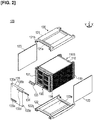
- Figure 2 is an exploded perspective view of Figure 1
- Figure 5 is a cross-sectional view of a main part in a state in which a busbar is joined to electrode tabs of stacked unit cells.
- Figure 6 is an exploded perspective view of a stack, busbars, a busbar holder, and terminals.
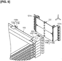
- Figure 9 is a perspective view showing a condition in which the busbar holder in which the busbars are assembled is assembled on spacers that constitute part of the stack.
- Figure 10 is a diagram showing a state in which the busbar holder in which the busbars are assembled is assembled on the spacers that constitute part of the stack.
- a plurality of the battery packs 100 are mounted in a vehicle such as an electric automobile, and the battery packs 100 are used as, inter alia, a power supply for driving a vehicular motor.
- the battery packs 100 are configured so that a stack 110S, which is formed by stacking as plurality of unit cells 110 as shown in Figure 2 , etc., is electrically connected by a busbar unit 130 in a state in which pressure is applied by a pressure-applying unit 120.
- the battery pack 100 is described in generic terms with reference to Figs. 9 and 10 , and is configured as follows.
- the battery pack 100 has a plurality of unit cells 110 that have electrode tabs 112, a plurality of busbars 132 that have connection surfaces 132f joined to the electrode tabs 112, first spacers 114 that support the electrode tabs 112, and a busbar holder 131 that retains the busbars 132.
- the first spacers 114 correspond to a support member
- the connection surfaces 132f of the busbars 132 correspond to connection portions with respect to the electrode tabs 112.
- the busbar holder 131 has pressing parts 131k that press the connection surfaces 132f of the busbars 132 toward the electrode tabs 112 supported by the first spacers 114.
- the configurations of the battery pack 100 are described below.
- Figure 11 is a perspective view showing a state in which the stack shown in Figure 2 is disassembled into individual unit cells, and spacers disposed at two ends are detached from an uppermost unit cell that is one of the unit cells.
- Figure 12 is a perspective view showing a condition in which cell sub-assemblies that are adjacent in the stacking direction are electrically connected by the busbars.
- the stack 110S is configured so that, as shown in Figs. 11 , 12 , etc., a first cell sub-assembly 110M composed of three unit cells 110 electrically connected in parallel and a second cell sub-assembly 110N composed of three unit cells 110 electrically connected in parallel are connected to each other in series in an alternating manner.
- the first cell sub-assembly 110M and the second cell sub-assembly 110N are configured in a similar manner. However, the first cell sub-assembly 110M and the second cell sub-assembly 110N are configured so that the three unit cells 110 thereof are vertically inverted, as shown in Figure 12 . Therefore, in the first cell sub-assembly 110M, positions of three anode-side electrode tabs 112A and of three cathode-side electrode tabs 112K are reversed with respect to those in the second cell sub-assembly 110N.
- the unit cells 110 correspond to, e.g., lithium ion secondary cells.
- a plurality of the unit cells 110 are connected in series to meet the specification for drive voltage of the vehicular motor.
- a plurality of the unit cells 110 are connected in parallel to ensure cell capacity and extend a travel distance of a vehicle.
- the unit cells 110 include power generation elements 111 that perform charging and discharging, electrode tabs 112 that expose the power generation elements 111 to the outside, and lamination films 113 that seal the power generation elements 111, as shown in Figure 5 .
- the power generation elements 111 Upon being charged by electric power from an outdoor charging stand, etc., the power generation elements 111 discharge to the vehicular motor, etc., and supply drive power.
- the power generation elements 111 are configured so that a plurality of sets of anodes and cathodes that are separated by separators are stacked.
- the electrode tabs 112 expose the power generation elements 111 to the outside, as shown in Figure 5 .
- the electrode tabs 112 are configured from anode-side electrode tabs 112A and cathode-side electrode tabs 112K.
- the anode-side electrode tabs 112A and the cathode-side electrode tabs 112K are brought out from cell bodies of the unit cells 110 in a same direction (long-axis direction X) that intersects a thickness direction of the cell bodies.
- At least two unit cells 110 are stacked as shown in Figure 12 .
- the anode-side electrode tabs 112A of one of the unit cells 110 and the cathode-side electrode tabs 112K of the other of the unit cells 110 are arranged in the stacking direction Z. Proximal ends of the anode-side electrode tabs 112A are joined to all anodes included in a single power generation element 111.
- the anode-side electrode tabs 112A are formed in the shape of a thin plate and are composed of aluminum (Al) in conformity with the characteristics of an anode. Proximal ends of the cathode-side electrode tabs 112K are joined to all cathodes included in a single power generation element 111.
- the cathode-side electrode tabs 112K are formed in the shape of a thin plate and are composed of copper (Cu) in conformity with the characteristics of a cathode.
- a thickness of the cathode-side electrode tabs 112K is equal to or less than a thickness of the anode-side electrode tabs 112A.
- the thickness of the cathode-side electrode tabs 112K is, e.g., half the thickness of the anode-side electrode tabs 112A.
- the electrode tabs 112 are formed to assume the shape of the letter "L" from proximal end parts 112c that are adjacent to the power generation elements 111 to the distal end parts 112d, as shown in Figure 5 .
- the distal end parts 112d of the electrode tabs 112 are bent downward in the Z direction so as to face an anode-side reverse surface or cathode-side reverse surface of the busbars 132.
- the distal end parts 112d of the electrode tabs 112 make planar contact with the busbars 132.
- the distal end parts 112d have spacer-abutting surfaces 112e that abut the first spacers 114, and busbar-abutting surfaces 112f that are in contact with the busbars 132 (see Figure 18 ).
- the lamination films 113 are formed in pairs and seal the power generation element 111 from above and below in the Z direction, as shown in Figure 5 .
- the pair of lamination films 113 have a rectangular outer periphery as shown in Figure 11 .
- the anode-side electrode tabs 112A and the cathode-side electrode tabs 112K are arranged outward from a gap formed by one-end parts 113a that are on one side of the rectangular outer periphery.
- the lamination films 113 are configured from: metal foils; and insulating sheets, the sheets covering the metal foils from above and below.
- the unit cells 110 are stacked as shown in Figure 5 while in a state of being supported by pairs of spacers (first spacers 114 and second spacers 115) as shown in Figure 11 .
- the pairs of spacers (first spacers 114 and second spacers 115) dispose the unit cells 110 at fixed intervals along the stacking direction Z, as shown in Figs. 5 and 11 .
- the first spacers 114 support the unit cells 110 on sides at which the electrode tabs 112 are brought out.
- Second spacers 115 support the unit cells 110 on opposite sides from the sides at which the electrode tabs 112 are brought out so that the second spacers 115 face opposite the first spacers 114 in the long-axis direction X of the unit cells 110.
- the first spacers 114 are composed of an insulating reinforced plastic and are formed in the shape of a long plate having recesses and protrusions as shown in Figs. 5 and 11 .
- the first spacers 114 are stacked together with the unit cells 110, and individual first spacers 114 are disposed adjacent to the unit cells 110 in the long-axis direction X.
- the first spacers 114 are provided so as to face opposite the one-end parts 113a of the pairs of lamination films 113.
- the first spacers 114 support the one-end parts 113a of the lamination films 113 by means of flat abutting surfaces 114b, as shown in Figure 5 .
- the first spacers 114 are provided with support surfaces 114h that are adjacent to the abutting surfaces 114b and that support the electrode tabs 112 on wall surfaces that are aligned in the stacking direction Z.
- the support surfaces 114h are positioned so that the distal end parts 112d of the electrode tabs 112 are aligned in the X direction, as shown in Figure 5 .
- the support surfaces 114h support the electrode tabs 112 against pressing from the busbar 132 side due to pressing parts 131k of the busbar holder 131 (described later).
- the first spacers 114 have anode-side support surfaces 114j that support the anode-side electrode tabs 112A, and cathode-side support surfaces 114k that support the cathode-side electrode tabs 114K, as the support surfaces 114h.
- the anode-side support surfaces 114j correspond to anode-side support portions in the present description
- the cathode-side support surfaces 114k correspond to cathode-side support portions.
- both ends of each of the abutting surfaces 114b that are aligned in the short-axis direction Y are provided with one of a pair of linking pins 114c that protrude upward, as shown in Figure 11 .
- the pairs of linking pins 114c are formed as circular columns and are inserted into linking holes 113c that open in both ends of the one-end parts 113a of the lamination films 113 that are aligned in the short-axis direction Y, thereby positioning the unit cells 110.
- first spacers 114 As shown in Figure 5 , upper surfaces 114a of the first spacers 114 and lower surfaces 114d of adjacent first spacers 114 abut each other. Circular-column-shaped positioning pins 114e that protrude from the upper surfaces 114a of the first spacers 114 are fitted into positioning holes 114f that open in the lower surfaces 114d of the adjacent first spacers 114, whereby the first spacers 114 are positioned with each other.
- the first spacers 114 are provided with locating holes 114g at two ends that are aligned in the short-axis direction Y, as shown in Figure 11 . Bolts that link together a plurality of battery packs 100 while positioning the battery packs 100 along the stacking direction Z are inserted into the locating holes 114g.
- Figure 9 is a perspective view showing a condition in which the busbar holder in which the busbars are assembled is assembled on spacers that constitute part of the stack.
- the battery pack 100 has linking parts 116-118 that link the busbar holder 131 to the first spacers 114.
- the linking parts 116 are disposed at first positions between the anode-side support surfaces 114j and the cathode-side support surfaces 114k in the short-axis direction Y.
- the linking parts 117 are disposed at second positions that are positioned further outward in the short-axis direction Y from the linking parts 116 at the first positions than are the anode-side support surfaces 114j.
- the linking parts 118 are disposed at third positions that are positioned further outward in the short-axis direction Y from the linking parts 116 at the first positions than are the cathode-side support surfaces 114k. A state of being elastically deformed is retained in deforming parts 131h in a state in which the busbar holder 131 is linked to the first spacers 114 by the linking parts 116-118.
- the linking parts 116-118 each have engaging parts 114m and engaging parts 131n.
- the engaging parts 114m are support-member-side engaging parts formed on the first spacers 114 in the present description.
- the engaging parts 114m are provided to front side surfaces of substantially cuboid end parts 114q that are provided to both short-axis-direction Y ends of the first spacers 114, as shown in Figure 10 .
- the engaging parts 114m are provided with: recesses 114n formed by notching front end parts of the end parts 114q, etc.; and catch parts 114p formed on edge parts of the recesses 114n, the catch parts 114p retaining the position of the busbar holder 131 relative to the first spacers 114.
- the hook-shaped engaging parts 131n provided to the busbar holder 131 are attached to the catch parts 114p.
- the recesses 114n are formed so as to notch the sides of the substantially cuboid end parts 114q, etc., at which the engaging parts 131n are attached.
- the end parts 114q are not limited to being of cuboid shape. A more detailed description is given below.
- the second spacers 115 are disposed adjacent to the unit cells 110 in the same manner as the first spacers 114 but do not need to support electrode tabs 112, and therefore are configured as simplifications of the first spacers 114.
- the second spacers 115 are provided with support surfaces 115b, positioning pins 115e, linking pins 115c, and locating holes 115g, as shown in Figure 11 .
- the support surfaces 115b support other-end parts 113b of the lamination films 113.
- the positioning pins 115e position the second spacers relative to each other.
- the linking pins 115c position the unit cells 110. Bolts that link together a plurality of battery packs 100 while positioning the battery packs 100 are inserted into the locating holes 115g.
- the second spacers 115 are also provided with configurations corresponding to the upper surfaces 114a, lower surfaces 114d, and positioning holes 114f of the first spacers 114, but these configurations are identical to those of the first spacers 114, and therefore detailed descriptions of these configurations are omitted.
- a pressure-applying unit 120 includes: an upper pressure-applying plate 121 and a lower pressure-applying plate 122, said plates applying pressure to the power generation elements 111 of individual unit cells 110 of the stack 110S from above and below; and a pair of side plates 123 that secure the pressure-applying plate 121 and the pressure-applying plate 122 in a state in which pressure is applied to the stack 110S.
- a casing that accommodates the stack 110S is configured from the pressure-applying plates 121, 122 and the side plates 123.
- the upper pressure-applying plate 121 applies pressure to the power generation elements 111 of individual unit cells 110 while retaining a plurality of unit cells 110 that constitute the stack 110S by sandwiching the same from above and below together with the lower pressure-applying plate 122, as shown in Figs. 1 and 2 .
- the pressure-applying plate 121 is formed in the shape of a plate provided with recesses and protrusions and is composed of a metal that is sufficiently rigid.
- the pressure-applying plate 121 is disposed along a horizontal plane.
- the pressure-applying plate 121 is provided with a pressure-applying surface 121a that applies downward pressure to the power generation elements 111, as shown in Figure 2 .
- the pressure-applying surface 121a is formed flat and protrudes downward from a central portion of the pressure-applying plate 121.
- the pressure-applying plate 121 is also provided with locating holes 121b into which bolts that link together the battery packs 100 are inserted.
- the locating holes 121b are formed as through-holes and open in four corners of the pressure-applying plate 121.
- the lower pressure-applying plate 122 is formed in the same shape as the upper pressure-applying plate 121 and is provided so as to be vertically reversed from the pressure-applying plate 121, as shown in Figure 2 .
- the pressure-applying plate 122 is provided with a pressure-applying surface 122a that applies upward pressure to the power generation elements 111, and locating holes 122b into which bolts that link together the battery packs 100 while positioning the battery packs 100 along the Z direction are inserted, in the same manner as the pressure-applying plate 121.
- the pair of side plates 123 secure the upper pressure-applying plate 121 and the lower pressure-applying plate 122 in a state in which pressure is applied to the stack 110S, as shown in Figs. 1 and 2 . Specifically, the pair of side plates 123 maintain a fixed interval between the pressure-applying plate 121 and the pressure-applying plate 122. The pair of side plates 123 also cover and protect side surfaces that are aligned in the long-axis direction X of the stacked plurality of unit cells 110.
- the side plates 123 are formed in the shape of a flat plate and are composed of a metal.
- the pair of side plates 123 are disposed in an upright state so as to face opposite two side surfaces along the long-axis direction X of the stacked plurality of unit cells 110.
- the pair of side plates 123 are welded to the pressure-applying plate 121 and the pressure-applying plate 122.
- Figure 3 is a partial expanded view of a front of a plurality of unit cells shown in Figure 2
- Figure 4 is an expanded view of a main part of the busbar unit.
- Figure 7 is a perspective view showing a state in which the busbars are assembled on the busbar holder
- Figure 8 is an exploded perspective view of Figure 7
- Figure 10 is a diagram showing a state in which the busbar holder in which the busbars are assembled is assembled on the spacers that constitute part of the stack.
- the busbar unit 130 is described in generic terms with reference to Figure 6 .
- the busbar unit 130 has a busbar holder 131, busbars 132, an anode-side terminal 133, a cathode-side terminal 134, and a protective cover 135. A more detailed description is given below.
- the busbar holder 131 integrally retains a plurality of busbars 132, as shown in Figure 3 .
- the busbar holder 131 integrally retains the plurality of busbars 132 in the form of a matrix so as to face the electrode tabs 112 of individual unit cells 110 of the stack 110S.
- the busbar holder 131 is composed of an insulating resin and is formed in the shape of a frame.
- the busbar holder 131 has brace parts 131a, reinforcing brace parts 131b, horizontal wall parts 131c, retaining parts 131d, the deforming parts 131h, the pressing parts 131k, openings 131m, and the engaging parts 131n, as shown in Figs. 6-10 .
- the brace parts 131a are provided in pairs on both short-axis-direction Y ends of the busbar holder 131 that is formed in the shape of a frame, as shown in Figure 6 .
- the pairs of brace parts 131a fit onto side surfaces of the first spacers 114.
- the pairs of brace parts 131a are formed to assume the shape of the letter "L" as viewed along the stacking direction Z and are formed in the shape of a plate extending along the stacking direction Z.
- the auxiliary brace parts 131b are of a shape that extends in the same vertical direction as the brace parts 131a and are positioned near an approximate center or middle of the busbar holder 131, as shown in Figure 6 .
- the busbars 132 are attached and retained between the brace parts 131a and the auxiliary brace parts 131b.
- the horizontal wall parts 131c are of a shape that connects the brace parts 131a and the auxiliary brace parts 131b and extend in a substantially horizontal direction (short-axis direction Y), as shown in Figure 6 .
- the busbars 132 are disposed in two rows in a horizontal direction (as is described later), and anode-side busbars 132A and cathode-side busbars 132K that are adjacent in the vertical direction (stacking direction Z) are joined to each other.
- the horizontal wall parts 131c are provided not only at both stacking-direction Z ends of the frame-shaped busbar holder 131 but also between adjacent busbars 132.
- the horizontal wall parts 131c disposed between adjacent busbars 132 prevent electrical discharge by insulating busbars 132 that are adjacent along the stacking direction Z.
- the busbar holder 131 can be configured so that the brace parts 131a, the auxiliary brace parts 131b, and the horizontal wall parts 131c are joined together, said parts being formed independently, or the busbar holder 131 can be configured so that the brace parts 131a, the auxiliary brace parts 131b, and the horizontal wall parts 131c are integrally molded.
- the retaining parts 131d are provided to retain the busbars 132 on the busbar holder 131.
- the retaining parts 131d have hook parts 131e and receiving parts 131f, as shown in Figure 10 .
- the hook parts 131e are configured in a shape of hooks that protrude inward from the brace parts 131a and the auxiliary brace parts 131b on a side of the busbar holder 131 at which the busbars 132 are inserted (attached).
- the receiving parts 131f constitute part of the retaining parts 131d that retain the busbars 132, and attach the pressing parts 131k and deforming parts 131h to the brace parts 131a and auxiliary brace parts 131b.
- the retaining parts 131d are provided in pairs for each single busbar 132 at both short-axis-direction Y ends of the busbars 132 so as to retain the busbars 132, as shown in Figure 10 .
- Groove parts 131g into which the busbars 132 are inserted are formed between the hook parts 131e and the receiving parts 131f.
- the busbars 132 are configured to have a clearance (gap) in the long-axis direction X and so as not to come into contact with both the hook parts 131e and the receiving parts 131f at the same time in the attached state.
- the busbars 132 are configured to have a clearance (gap) in the short-axis direction Y and so as not to come into contact with both the brace parts 131a and the auxiliary brace parts 131b at the same time.
- the receiving parts 131f are configured in a planar shape extending in the short-axis direction Y in the present embodiment, as shown in Figure 10 , etc.
- the shape of the receiving parts 131f is not particularly limited as long as it is possible to attach the deforming parts 131h and the pressing parts 131k to the brace parts 131a and the auxiliary brace parts 131b.
- the deforming parts 131h connect the retaining parts 131d and the pressing parts 131k.
- the deforming parts 131h are configured to be elastically deformable, and, in an elastically deformed state, urge the pressing parts 131k with a repulsive force in a direction in which the pressing parts 131k are caused to move toward the electrode tabs 112.
- the deforming parts 131h have U-shaped leg parts 131j that extend between the retaining parts 131d and the pressing parts 131k so as to project in a direction away from to-be-pressed surfaces 132e of the busbars 132.
- the deforming parts 131h are provided in pairs in the short-axis direction Y across the pressing parts 131k for each single busbar 132, as shown in Figure 10 .
- the pressing parts 131k to press the to-be-pressed surfaces 132e of the busbars 132 toward the electrode tabs 112 and to bond the to-be-pressed surfaces 132e to the electrode tabs 112 at locations inward from retaining portions of the busbars 132.
- the deforming parts 131h deform so as to change a position in the long-axis direction X when the electrode tabs 112 and the busbars 132 are attached, or to change a position of the pressing parts 131k in accordance with a variation in shape (see the deforming parts 131h1, 131h2 and the pressing parts 131k1, 131k2 in Figure 4 ). This causes the pressing parts 131k (described later) to individually bond all of the busbars 132 in the busbar unit 130 to all of the electrode tabs 112.
- the deforming parts 131h are configured to be disposed so as to approach further inward from the busbars 132 than are the retaining parts 131d in a direction (short-axis direction Y in Figure 10 ) along contact surfaces of the busbars 132.
- the pressing parts 131k press connection surfaces 132f of the busbars 132 toward the electrode tabs 112 supported by the first spacers 114. More specifically, the pressing parts 131k press the plurality of busbars 132 retained by the retaining parts 131d of the busbar holder 131 toward the electrode tabs 112, from the to-be-pressed surfaces 132e on opposite sides from the connection surfaces 132f toward the support surfaces 114h of the first spacers 114.
- the pressing parts 131k have pressing surfaces 131u that make planar contact with the to-be-pressed surfaces 132e of the busbars 132, as shown in Figure 10 . In the present description, the pressing parts 131k are located at pressing sites of the busbars 132.
- the pressing parts 131k press the to-be-pressed surfaces 132e of the busbars 132 located inward from the retaining parts 131d toward the electrode tabs 112, as indicated by arrows in Figure 20 .
- locations that can come into contact with the retaining parts 131d function as securing points in a state in which the busbar holder 131 is attached to the stack 110S.
- locations that come into contact with the pressing parts 131k are formed in curved or otherwise non-flat shapes when the pressing parts 131k are not present.
- the pressing parts 131k suppress the connection surfaces 132f of the busbars 132 from being formed in curved or otherwise non-flat shapes, bring the busbars 132 and the electrode tabs 112 into contact together with the support surfaces 114h of the first spacers 114, and bond the busbars 132 and the electrode tabs 112.
- the pressing parts 131k are divided from the retaining parts 131d by the deforming parts 131h and are configured so that all of the busbars 132 included in the battery pack 100 are positioned to be individually bonded to the electrode tabs 112 in a state in which the busbar unit 130 is attached to the stack 110S. More specifically, a distance from spacer-attachment surfaces of the busbar holder 131 to the connection surfaces 132f of the busbars 132 prior to assembly is set to be less than a distance from busbar-holder-attachment end surfaces of the first spacers 114 to the busbar-abutting surfaces 112f of the electrode tabs 112 (see distance d in Figure 10 ).
- Adopting such a configuration makes it possible to bond all of the busbars 132 to the electrode tabs 112 even if there is assembly error or dimensional variation between components of the busbars 132, the electrode tabs 112, etc.
- the pressing parts 131k are set to have higher bending strength than the busbars 132 so that the connection surfaces 132f, etc., of the busbars 132 do not separate from the electrode tabs 112.
- sites of the pressing parts 131k which are configured from a resin material, etc., in contrast to the busbars 132 composed of metal, etc., are configured to be sufficiently thick relative to the plate thickness of the metal busbars 132.
- the pressing parts 131k constitute contact sites of the busbars 132.
- the pressing parts 131k are configured so that a plurality of cross-sectional surfaces extending vertically and horizontally as shown in Figure 8 are disposed in a rod-form configuration. More specifically, the pressing parts 131k have two rod-shaped members 131p, 131q that extend horizontally, and a rod-shaped member 131r positioned between the pair of deforming parts 131h, as shown in Figure 8 .
- the rod-shaped members 131p, 131q are disposed parallel to the vertical direction as shown in Figure 8 , and laser light can be directed between the rod-shaped member 131p and the rod-shaped member 131q, thereby making it possible to avoid interference of the laser light and join the busbars 132 to the electrode tabs 112.
- the pressing parts 131k also have anode-side pressing parts 131s that press the anode-side busbars 132A, and cathode-side pressing parts 131t that press the cathode-side busbars 132K, as shown in Figure 8 .
- the pressing parts 131k are thus configured to impart pressing force in component units and to separately press the anode-side busbars 132A and the cathode-side busbars 132K that constitute the busbars 132.
- the pressing parts 131k are also are configured so that only one of the rod-shaped members 131p, 131q is provided at a site for attaching the anode-side terminal 133 and cathode-side terminal 134 (described later), as shown in Figure 3 , and so that the terminals 133, 134 can be attached.
- the openings 131m are formed as openings provided to the rod-shaped members 131r of the pressing parts 131k as shown in Figure 8 , and can be used to confirm, inter alia, a gap with respect to a component on an inner part (inner side) from the busbars 132 during, e.g., a welding operation.
- Three openings 131m are provided in the center of the pressing parts 131k in Figure 8 , but the location and number of openings 131m are not limited to this configuration.
- the engaging parts 131n constitute part of the linking parts 116-118 and are busbar-holder-side engaging parts formed on the busbar holder 131.
- the engaging parts 131n enter the recesses 114n of the engaging parts 114m of the first spacers 114 as shown in Figure 10 and are caught on the catch parts 114p, thereby linking the busbar holder 131 to the first spacers 114.
- the engaging parts 131n are configured so as to be provided with a pair of shapes protruding outward in directions intersecting the insertion direction, as shown in Figure 10 , and are also configured so that corresponding portions are caught on the catch parts 114p of the spacers 114.
- a single component composed of a resin material, etc. is formed from the brace parts 131a to the engaging parts 131n.
- the anode-side busbars 132A connected to the anode-side electrode tabs 112A and the cathode-side busbars 132K connected to the cathode-side electrode tabs 112K are joined and integrally formed, as shown in Figs. 6 and 8 .
- the anode-side busbars 132A and the cathode-side busbars 132K have contact parts 132a, engaging parts 132b, joining parts 132c, and openings 132d.
- the anode-side busbars 132A and the cathode-side busbars 132K are molded by bending plate-form members to prescribed shapes.
- the contact parts 132a have the to-be-pressed surfaces 132e that are pressed by the pressing parts 131k of the busbar holder 131, and the connection surfaces 132f that are provided on the opposite side from the to-be-pressed surfaces 132e and come into contact with the busbar-abutting surfaces 112f of the electrode tabs 112.
- the pressing parts 131k of the busbar holder 131 come into contact with the to-be-pressed surfaces 132e at a substantially central part of the busbars 132.
- connection surfaces 132f are joined to the electrode tabs 112 at busbar-abutting surfaces 112f that are on the opposite side of the electrode tabs 112 from the spacer-abutting surfaces 112e abutting the first spacers 114, at connection portions on the busbars 132 with respect to the electrode tabs 112 (see Figure 18 ).
- the engaging parts 132b are provided to both short-axis-direction Y ends of the plate shape and are provided to retain the busbars 132 by means of the retaining parts 113d of the busbar holder 131.
- the engaging parts 132b are configured so that end parts of a plate member are bent in the shape of the letter "L,” but the shape of the engaging parts 132b is not limited to this shape as long as the busbars 132 can be attached to and retained by the busbar holder 131.
- the joining parts 132c are located at one end part of one stacking-direction Z plate member during attachment and are such that the anode-side busbars 132A and the cathode-side busbars 132K are joined at that site to constitute the busbars 132.
- the joining parts 132c are configured so that the end part of the plate member is bent in Figs. 7 and 8 , but the end part does not have to be bent as long as joining is possible.
- the openings 132d are configured to allow communication with the openings 131m during assembly onto the busbar holder 131.
- the busbars 132 electrically connect the electrode tabs 112 of the unit cells 110 arranged vertically, as shown in Figs. 5, 6 , and 12 .
- the busbars 132 electrically connect the anode-side electrode tabs 112A of one unit cell 110 and the cathode-side electrode tabs 112K of an adjacent unit cell 110.
- the busbars 132 electrically connect, e.g., the three vertically arranged anode-side electrode tabs 112A of the first cell sub-assembly 110M and the three vertically arranged cathode-side electrode tabs 112K of the second cell sub-assembly 110N, as shown in Figure 12 .
- the busbars 132 e.g., connect in parallel the three anode-side electrode tabs 112A of the first cell sub-assembly 110M and connect in parallel the three cathode-side electrode tabs 112K of the second cell sub-assembly 110N, as shown in Figure 12 . Furthermore, the busbars 132 serially connect the three anode-side electrode tabs 112A of the first cell sub-assembly 110M and the three cathode-side electrode tabs 112K of the second cell sub-assembly 110N.
- the plate thickness of the anode-side busbars 132A is equal to or greater than the plate thickness of the anode-side electrode tabs 112A, and is, e.g., no more than three times the plate thickness of the anode-side electrode tabs 112A.
- the anode-side busbars 132A are composed of aluminum, similarly to the anode-side electrode tabs 112A.
- the cathode-side busbars 132K are composed in the same shape as the anode-side busbars 132A, except in regard to plate thickness.
- the plate thickness of the cathode-side busbars 132K is equal to or less than the plate thickness of the anode-side busbars 132A.
- the plate thickness of the cathode-side busbars 132K is equal to or greater than the plate thickness of the cathode-side electrode tabs 112K, and is, e.g., no more than three times the plate thickness of the cathode-side electrode tabs 112K.
- the cathode-side busbars 132K are composed of copper, similarly to the cathode-side electrode tabs 112K.
- busbars 132 set in the form of a matrix correspond to an anode-side endpoint of twenty-one unit cells 110 (three connected in parallel, seven connected in series) and are configured from only the anode-side busbars 132A.
- the anode-side busbars 132A are welded to the anode-side electrode tabs 112A of the three uppermost unit cells 110 from among the stacked unit cells 110.
- busbars 132 set in the form of a matrix correspond to a cathode-side endpoint of twenty-one unit cells 110 (three connected in parallel, seven connected in series) and are configured from only the cathode-side busbars 132K.
- the cathode-side busbars 132K are welded to the cathode-side electrode tabs 112K of the three lowermost unit cells 110 from among the stacked unit cells 110.
- the anode-side terminal 133 exposes the anode-side endpoint of the electrically connected plurality of unit cells 110 to an external input/output terminal, as shown in Figs. 1 and 2 .
- the anode-side terminal 133 joins to the anode-side busbars 132A positioned in the upper right of the drawing from among the busbars 132 that are set in the form of a matrix, as shown in Figure 2 .
- the anode-side terminal 133 is formed in the shape of a plate in which both ends are bent and is composed of an electroconductive metal.
- the cathode-side terminal 134 exposes the cathode-side endpoint of the electrically connected plurality of unit cells 110 to an external input/output terminal, as shown in Figs. 1 and 2 .
- the cathode-side terminal 134 joins to the cathode-side busbars 132K positioned in the lower left of the drawing from among the busbars 132 that are set in the form of a matrix, as shown in Figure 2 .
- the cathode-side terminal 134 is formed in the same shape as the anode-side terminal 133, but is vertically inverted.
- the protective cover 135 protects the busbars 132, etc., as shown in Figs. 1 and 2 .
- the protective cover 135 integrally covers the busbar holder 131 that includes the plurality of busbars 132, thereby preventing the individual busbars 132 from coming into contact with other members, etc., and producing an electrical short-circuit.
- the protective cover 135 is composed of an insulating plastic and is formed such that an upper end 135b and a lower end 135c of a side surface 135a that is upright along the stacking direction Z are bent toward the X direction in the same manner as hooks, as shown in Figure 2 .
- the protective cover 135 secures the busbar holder 131 by sandwiching the same from above and below with the upper end 135b and the lower end 135c while covering the individual busbars 132 by means of the side surface 135a.
- the protective cover 135 is configured so that each of a first opening 135d, which is formed as a rectangular hole and exposes the anode-side terminal 133 to the outside, and a second opening 135e, which is formed as a rectangular hole and exposes the cathode-side terminal 134 to the outside, are provided to the side surface 135a.
- FIG. 13 is a flow chart showing a method for manufacturing a battery pack according to an embodiment of the present invention.
- the method for manufacturing the battery pack 100 according to the present embodiment includes stacking constituent members, applying pressure to the stacked members, and passing electricity between the unit cells 110, as is generally apparent with reference to Figure 13 .
- a stack 110S is formed by stacking unit cells 110 that have electrode tabs 112 together with the second spacers 115 and the first spacers 114 that support the electrode tabs 112. The following operations are performed in passing electricity between the unit cells.
- the busbar holder 131 in which are retained the plurality of busbars 132 having connection surfaces 132f to be joined to the electrode tabs 112 is disposed so that the electrode tabs 112 supported by the first spacers 114 face each other.
- the busbars 132 retained by the busbar holder 131 are then pressed toward the electrode tabs 112 by the pressing parts 131k of the busbar holder 131.
- the busbars 132 and the electrode tabs 112 are then joined in a state in which the busbars 132 and the electrode tabs 112 are pressed toward each other.
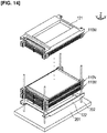
- Figure 14 is a perspective view schematically showing a state in which members that constitute part of the battery pack are sequentially stacked.
- a placement platform 201 provided with a placement surface that is substantially parallel to the horizontal plane.
- Locating pins 202 for positioning the stacked pressure-applying plate 122, first cell sub-assembly 110M, second cell sub-assembly 110N, and pressure-applying plate 121 in relation to the long-axis direction X and the short-axis direction Y are installed at prescribed intervals in the placement platform 201.
- the intervals between the locating pins 202 correspond to, inter alia, intervals between the locating holes 121b in the pressure-applying plate 121.
- the members constituting the battery pack 100 are stacked using, inter alia, a robot arm, a hand lifter, and a vacuum-suction-type collet.
- the locating holes 122b in the pressure-applying plate 122 are inserted onto the locating pins 202 using a robot arm or the like, and the pressure-applying plate 122 is lowered along the stacking direction Z to place on the placement surface of the placement platform 201, as shown in Figure 14 .
- the locating holes 114g, 115g in the second cell sub-assembly 110N and the first cell sub-assembly 110M are then inserted onto the locating pins 202, and the cell sub-assemblies 110M, 110N are lowered along the stacking direction Z to stack on the pressure-applying plate 122.
- the stack 110S is formed by stacking the unit cells 110 having the electrode tabs 112 together with the second spacers 115 and the first spacers 114 that have the support surfaces 114h with which the electrode tabs 112 come into contact.
- the locating holes 121b in the pressure-applying plate 121 are inserted onto the locating pins 202, and the pressure-applying plate 121 is stacked. This results in a state in which the stack 110S is disposed between the pressure-applying plates 121, 122 (ST1).
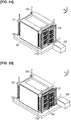
- Figure 15 is a perspective view schematically showing a state in which constituent members of the battery pack are pressed from above
- Figure 16 is a perspective view schematically showing a state in which the side plates and the pressure-applying plates are welded.
- a pressure-applying jig 203 in which pressure-applying parts are supported by support parts is used during application of pressure.
- the support parts are linked to a hydraulic cylinder and/or an electromotive stage for driving along the stacking direction Z.
- the pressure-applying parts move vertically along the stacking direction Z via the support parts and impart pressure to the pressure-applying plate 121.
- the pressure-applying jig 203 is lowered and caused to abut the pressure-applying plate 121. Pressure is then imparted through the pressure-applying plate 121 along the stacking direction Z to the stack 110S that is disposed between the pressure-applying plates 121, 122 (ST2).
- a laser oscillator 204 is used during joining (referred to as first joining below) of the side plates 123 and the pressure-applying plates 121, 122.
- the laser oscillator 204 is a light source for joining the side plates 123 to the pressure-applying plates 121, 122.
- the laser oscillator 204 is configured from, e.g., an yttrium-aluminum-garnet (YAG) laser.
- An optical path of laser light L1 emitted from the laser oscillator 204 is produced by, e.g., an optical fiber or a mirror, and upper ends or lower ends of the side plates 123 are irradiated with the laser light L1 in a state in which the laser light L1 is collected by a collecting lens.
- the laser light L1 can be configured to be branched by, e.g., a half-mirror and directed on both the upper ends and the lower ends of the side plates 123 at the same time.
- a plurality of locations on the upper ends and the lower ends of the side plates 123 are irradiated with the laser light L1 from the laser oscillator 204, and joining is performed by seam welding (ST3).
- the pressure-applying jig 203 stops applying pressure to the pressure-applying plate 121 at this point in time and is separated from the pressure-applying plate 121.
- Figure 17 is a perspective view schematically showing a state in which the busbar unit is attached to a stack
- Figs. 18-20 are diagrams illustrating a situation where the busbars are attached to the busbar holder and the busbar holder to which the busbars are attached is attached to the stack that includes spacers.
- Figure 21 is a perspective view schematically showing a state in which the busbars constituting part of the busbar unit are welded to the electrode tabs.
- Figure 22 is a perspective view schematically showing a situation where an anode-side terminal is welded to an anode-side busbar, and a cathode-side terminal is welded to a cathode-side busbar.
- a plurality of busbars 132 are attached to the busbar holder 131, and the busbar holder 131 to which the busbars 132 are attached is attached to the stack 110S that includes the first spacers 114. Joining (referred to as second joining below) of the busbars 132 and the electrode tabs 112, and joining of the terminals 133, 134 and the busbars 132, are then performed.
- the protective cover 135 is attached to the stack 110S so as to cover the busbar unit 130. A more detailed description is given below.
- busbars 132 and the busbar holder 131 are prepared as shown in Figure 18 , the placement platform 201 is rotated, and the site where the busbar unit 130 is disposed is caused to face the laser oscillator 204.
- the pressing parts 131k and the deforming parts 131h are caused to deform (flex) somewhat starting from the pressing parts 131k of the busbar holder 131, and an interval between pairs of retaining parts 131d is increased to insert the engaging parts 132b of the busbars 132 into the groove parts 131g.
- the engaging parts 132b have been inserted into the groove parts 131g in the long-axis direction of the busbars 132, the deformation of the deforming parts 131h and the pressing parts 131k is released. This results in a state in which the busbars 132 are temporarily held by the busbar holder 131, as shown in Figure 19 .
- the engaging parts 131n of the busbar holder 131 which constitute part of the linking parts 116-118, are then elastically deformed and fitted into the catch parts 114p of the engaging parts 114m of the first spacers 114.
- the busbar holder 131 that includes the busbars 132 is thus linked to the stack 110S that includes the first spacers 114 by means of the linking parts 116-118. The state in which the deforming parts 131h are elastically deformed is thereby retained.
- the busbars 132 are then joined to the electrode tabs 112. Specifically, as shown in Figure 21 , the laser light L1 is directed from the laser oscillator 204 toward the busbars 132, and the busbars 132 and the distal end parts 112d of the anode-side electrode tabs 112A or cathode-side electrode tabs 112K are joined by spot welding or seam welding (ST4).
- the anode-side terminal 133 is then joined to the anode-side busbars 132A positioned at the anode-side endpoint, as shown in Figure 22 .
- the cathode-side terminal 134 is joined to the cathode-side busbars 132K positioned at the cathode-side endpoint.
- Figure 23 is a perspective view schematically showing a state in which the protective cover is attached to the stack.
- the robot arm is used to attach the protective cover 135 to the busbar holder 131 while fitting the upper end 135b and the lower end 135c of the protective cover 135 onto the busbar holder 131.
- the upper end 135b and the lower end 135c of the protective cover 135 can be joined to the busbar holder 131 by an adhesive agent.
- the completely manufactured battery pack 100 is extracted from the locating pins 202, removed from the placement platform 201, and sent to, inter alia, an inspection step for inspecting battery performance, etc.
- the manufacturing method described above can be performed by any of an automated apparatus in which all of the steps are controlled by a controller, a semi-automated apparatus in which some of the steps are handled by an operator, or a manual apparatus in which all of the steps are handled by an operator.
- the battery pack 100 in the present embodiment has the plurality of unit cells 110 that have the electrode tabs 112, the plurality of busbars 132 that have the connection surfaces 132f joined to the electrode tabs 112, the first spacers 114 that support the electrode tabs 112, and the busbar holder 131 that retains the busbars 132.
- the busbar holder 131 has the pressing parts 131k that press the connection surfaces 132f of the busbars 132 toward the electrode tabs 112 supported by the first spacers 114.
- the method for manufacturing the battery pack 100 includes the following operations. First the stack 110S is formed by stacking the unit cells 110 having the electrode tabs 112 together with the first spacers 114 that support the electrode tabs 112. The busbar holder 131 in which are retained the plurality of busbars 132 having the connection surfaces 132f to be joined to the electrode tabs 112 is then disposed so as to face the electrode tabs 112 supported by the first spacers 114. The busbars 132 retained by the busbar holder 131 are then pressed toward the electrode tabs 112 by the pressing parts 131k of the busbar holder 131. The busbars 132 and the electrode tabs 112 are then joined in a state in which the busbars 132 and the electrode tabs 112 are pressed toward each other.
- the busbar holder 131 also has the elastically deformable deforming parts 131h.
- the deforming parts 131h urge the pressing parts 131k with a repulsive force in a direction in which the pressing parts 131k are caused to move toward the electrode tabs 112.
- the deformation of the elastically deformable deforming parts 131h of the busbar holder 131 urges the pressing parts 131k with a repulsive force in a direction in which the pressing parts 131k are caused to move toward the electrode tabs 112.
- the repulsive force produced by the elastic deformation of the deforming parts 131h in this manner is used to make it possible to maintain a state in which the busbars 132 are in contact with the electrode tabs 112.
- the deforming parts 131h are configured to have the U-shaped leg parts 131j that extend so as to project in a direction away from the busbars 132.
- the unit cells 110, etc., that produce electric power are present on the joining-surface side of the busbars 132, and therefore from the standpoint of space, it is inefficient to provide the U shape on the joining-surface side of the busbars 132.
- the pressing parts 131k readily deform in an arcuate shape toward the protective cover 135 opposing the busbars 132, and the busbars 132 sometimes are difficult to press toward the electrode tabs 112 in such cases.
- the deforming parts 131h have the leg parts 131j that extend so as to project in a direction away from the busbars 132, thereby making it possible to press the electrode tabs 112 in a manner that is efficient from the standpoint of space and pressing force.
- the U shape of the deforming parts 131h is disposed so as to approach further inward (substantially toward a center) from the busbars 132 than are the retaining parts 131d in the short-axis direction Y (direction along the contact surfaces of the busbars 132) in Figure 10 .
- An opening shape, etc., for visually confirming gaps between the busbars and the electrode tabs is sometimes provided to the busbar holder 131. Even in such cases, adopting the configuration described above makes it possible to dispose the deforming parts 131h in the busbar holder 131 in a compact manner without disrupting the function of the opening shape.
- the pressing parts 131k have pressing surfaces 131u that make planar contact with the busbars 132. Therefore, it is possible to accommodate gaps between the busbars 132 and the electrode tabs 112 and to sufficiently cause these components to come into contact or bond together. In addition, due to the pressing parts 131k making planar contact with the to-be-pressed surfaces 132e of the busbars 132, it is possible to prevent damage near local sections of the busbars 132 and to increase the deflection margin of the busbars 132.
- At least two of the unit cells 110 are stacked, and the anode-side electrode tabs 112A of one of the unit cells 110 and the cathode-side electrode tabs 112 of the other unit cell 110 are arranged in the stacking direction Z of the unit cells 110.
- the busbars 132 are integrally formed by joining the anode-side busbars 132A connected to the anode-side electrode tabs 112A and the cathode-side busbars 132K connected to the cathode-side electrode tabs 112K.
- the busbar holder 131 has the anode-side pressing parts 131s that press the anode-side busbars 132A, and the cathode-side pressing parts 131t that press the cathode-side busbars 132K, as the pressing parts 131k.
- Twisting of the contact parts 132a or engaging parts 132b sometimes occurs in the busbars 132 due to the joining when the anode-side busbars 132A and the cathode-side busbars 132K are joined. Even in such cases, adopting a configuration so as to have pressing parts for each of the anode-side busbars and the cathode-side busbars as described above makes it possible to bring the busbars 132 and the electrode tabs 112 into contact in a state in which twisting of the busbars 132 is accommodated or mitigated and to join these components.
- connection surfaces 132f of the anode-side busbars 132A and the cathode-side busbars 132K are positioned in the same plane, but sometimes joining occurs in a state in which one set of busbars is positioned at an incline relative to the other due to variation. Even in such cases, providing the anode-side pressing parts 131s and the cathode-side pressing parts 131t makes it possible to bring the anode-side busbars 132A and the cathode-side busbars 132K into contact with individual electrode tabs 112 and to join these components.
- the battery pack 100 further includes the linking parts 116-118 that link the busbar holder 131 to the first spacers 114.
- a state of being elastically deformed is retained in the deforming parts 131h in a state in which the busbar holder 131 is linked to the first spacers 114 by the linking parts 116-118.
- the state in which the deforming parts 131h are elastically deformed is retained due to the busbar holder 131 being linked to the first spacers 114 by the linking parts 116-118. This makes it possible to implement a joining operation without retaining the busbar holder 131, to which the busbars 132 are attached, by means of a jig or a robot when the busbars 132 are to be joined to the electrode tabs 112.
- the linking parts 116-118 include the engaging parts 114m formed on the first spacers 114, and the engaging parts 131n formed on the busbar holder 131.
- the linking parts 116-118 link the busbar holder 131 to the first spacers 114 due to engagement of the engaging parts 114m and the engaging parts 131n. This makes it possible to configure the engaging parts 114m and the engaging parts 131n by fitting, etc., and to link the busbar holder 131 to the first spacers 114.
- the anode-side electrode tabs 112A and the cathode-side electrode tabs 112K are arranged on one side on the outer periphery of the rectangular lamination films 113.
- the first spacers 114 have anode-side support surfaces 114j that support the anode-side electrode tabs 112A, and cathode-side support surfaces 114k that support the cathode-side electrode tabs 112K.
- the linking parts 116 are disposed at first positions between the anode-side support surfaces 114j and the cathode-side support surfaces 114k.
- the linking parts 117 are disposed at second positions that are positioned further outward from the linking parts 116 than are the anode-side support surfaces 114j.
- the linking parts 118 are disposed at third positions that are positioned further outward from the linking parts 116 than are the cathode-side support surfaces 114k. Adopting such a configuration makes it possible to stabilize a retaining force of the busbar holder 131 relative to the first spacers 114 to a greater extent than when a configuration includes linking parts 117, 118 at two locations. Accordingly, it is possible to further stabilize the pressing of the anode-side busbars 132A relative to the anode-side electrode tabs 112A and the pressing of the cathode-side busbars 132K relative to the cathode-side electrode tabs 112K.
- the present invention is not limited to the embodiment described above; various changes and modifications can be made herein without departing from the scope of the claims.
- a single component is formed from the brace parts 131a to the engaging parts 131n.
- the present invention is not limited to this configuration; the retaining parts 131d, the deforming parts 131h, and the pressing parts 131k can be configured as separate components from at least the brace parts 131a, the auxiliary brace parts 131b, and the horizontal wall parts 131c, and a configuration can be adopted in which these two sets of parts are integrated by fitting or bonding.
- the deforming parts 131h are used to urge the pressing parts 131k with a repulsive force in a direction in which the to-be-pressed surfaces 132e of the busbars 132 are caused to move toward the support surfaces 114h of the first spacers 114.
- the present invention is not limited to this configuration; the deforming parts 131h are not an essential portion of the configuration, and the following configuration can be adopted as the configuration for causing the to-be-pressed surfaces 132e of the busbars 132 to move.
- pressing parts can be configured from fixed parts, movable parts capable of moving relative to the fixed parts, and coil springs disposed between the fixed parts and the movable parts.
- a configuration can be adopted in which repulsive force produced by elastic deformation of the springs presses the busbars 132 toward the electrode tabs 112.
- the shape of the busbars 132 is not corrected during attachment to the busbar holder 131 shown in Figs. 18 and 19 , but the shape is corrected during attachment of the busbar holder 131 to the first spacers 114 shown in Figs. 19 and 20 .
- the present invention is not limited to this configuration; the busbars 132 can be such that the shape of the contact parts 132a is corrected to a certain degree during attachment to the busbar holder 131 shown in Figure 18 and 19 .
- gaps between the busbars 132 and the electrode tabs 112 are corrected from a state in which the contact parts 132a of the busbars 132 have a recessed shape relative to the electrode tabs 112, as shown in Figure 18 .
- the present invention is not limited to this configuration; in addition to the above, using the busbar holder 131 makes it possible to correct gaps between the contact parts 132a of the busbars 132 and the electrode tabs 112 even when the contact parts 132a have a projecting shape relative to the electrode tabs 112, and to sufficiently cause these components to come into contact.
- the position of the busbar unit 130 relative to the stack 110S is retained by the linking parts 116-118 during joining of the busbars 132 and the electrode tabs 112.
- the linking parts 116-118 are not essential; instead of the above, the position of the busbar unit 130 relative to the stack 110S can be retained by a jig, or the busbar unit 130 can be retained by a robot hand, etc., during joining.
Landscapes
- Chemical & Material Sciences (AREA)
- Chemical Kinetics & Catalysis (AREA)
- Electrochemistry (AREA)
- General Chemical & Material Sciences (AREA)
- Inorganic Chemistry (AREA)
- Battery Mounting, Suspending (AREA)
- Connection Of Batteries Or Terminals (AREA)
Abstract
Description
- The present invention relates to a battery pack, a busbar holder used in a battery pack, and a method for manufacturing a battery pack.
- In recent years, the automotive industry has grappled with the development of secondary cells, fuel cells, and other such devices that have a low impact on the environment in order to reduce gas emissions from automobiles. For example, low output is obtained from unit cells composed of a positive electrode, a negative electrode, a separator, etc., in secondary cells, and the unit cells are therefore often used in stacked form. Such products are referred to as "battery packs." In battery packs, individual electrode tabs are brought out from inside of the plurality of unit cells. The plurality of electrode tabs that are brought out are connected to busbars or other such components, and electric power is delivered to the outside.
- A plurality of busbars are prepared in accordance with how many unit cells are stacked together. However, sometimes the plurality of busbars are assembled in a state of being held integrally by a separate member, as indicated in Patent Literature 1, etc., from the standpoint of assembly operation efficiency, etc. (see Patent Literature 1).
- Patent Literature 1: Japanese Patent Application Publication No.
2012-515418 - In battery packs, thin-plate-shaped members are molded into prescribed shapes as busbars, and the busbars are joined to electrode tabs in a state in which a prescribed number of the busbars are joined. A plurality of joining locations for the busbars and electrode tabs are provided in battery packs, but variations between independent components, variations in assembly, etc., are present in the busbars and the electrode tabs in the same manner as with other components, and these variations can accumulate. At the plurality of joining locations in the battery pack, the positions of the electrode tabs and the busbars can vary depending on the location, a gap can be produced between the electrode tabs and the busbars, and it can become difficult to perform an operation for bringing the electrode tabs and the busbars into contact so as to enable joining at all of the plurality of joining locations. The inventors investigated improvements in a joining operation with respect to these points.
- An object of the present invention is to provide: a battery pack in which it is possible to accommodate gaps that can be produced between electrode tabs and busbars, easily bring each of the electrode tabs and busbars present at a plurality of locations into contact, and join the electrode tabs and busbars; a busbar holder used in a battery pack; and a method for manufacturing a battery pack.
- A battery pack according to an aspect of the present invention, which achieves the object described above, has a plurality of unit cells that have electrode tabs, a plurality of busbars that have connection portions joined to the electrode tabs, a support member that support the electrode tabs, and a busbar holder that retains the plurality of busbars. The busbar holder is provided with pressing parts that press the connection portions of the busbars toward the electrode tabs supported by the support member. Another aspect of the present invention includes a busbar holder used in the battery pack described above, the busbar holder being provided with the retaining parts and the pressing parts.
- A further aspect of the present invention, which achieves the object described above, is a method for manufacturing a battery pack. In this method, a stack is formed by stacking unit cells that have electrode tabs together with a support member that support the electrode tabs. The busbar holder in which are retained the plurality of busbars having connection portions to be joined to the electrode tabs is then disposed so as to face the electrode tabs supported by the support member. The busbars retained by the busbar holder are then pressed toward the electrode tabs by pressing parts of the busbar holder. The busbars and the electrode tabs are then joined in a state in which the busbars and the electrode tabs are pressed toward each other.
-
-
Figure 1 is a perspective view of a battery pack according to an embodiment of the present invention; -
Figure 2 is a perspective view showing a state in which a pressure-applying unit (upper and lower pressure-applying plates and left and right side plates) is detached from the battery pack shown inFigure 1 , and in which a protective cover and parts (anode-side terminal and cathode-side terminal) of a busbar unit are detached; -
Figure 3 is a partial expanded view of a front of a plurality of unit cells shown inFigure 2 ; -
Figure 4 is a partial expanded view of a main part of the busbar unit; -
Figure 5 is a cross-sectional view of the main part in a state in which busbars are joined to electrode tabs of stacked unit cells; -
Figure 6 is an exploded perspective view of a stack, busbars, a busbar holder, and terminals; -
Figure 7 is a perspective view partially showing a state in which the busbars are attached to the busbar holder; -
Figure 8 is a perspective view showing a state in which the busbars and the busbar holder inFigure 7 are disassembled; -
Figure 9 is a perspective view showing a condition in which the busbar holder in which the busbars are assembled is assembled on spacers that constitute part of the stack; -
Figure 10 is a diagram showing a state in which the busbar holder in which the busbars are assembled is assembled on the spacers that constitute part of the stack; -
Figure 11 is a perspective view showing a state in which the stack shown inFigure 2 is disassembled into individual unit cells, and spacers disposed at two ends are detached from an uppermost unit cell that is one of the unit cells; -
Figure 12 is a perspective view showing a condition in which cell sub-assemblies that are adjacent in a stacking direction are electrically connected by busbars; -
Figure 13 is a flow chart showing a method for manufacturing a battery pack according to an embodiment of the present invention; -
Figure 14 is a perspective view schematically showing a state in which members that constitute part of the battery pack are sequentially stacked; -
Figure 15 is a perspective view schematically showing a state in which constituent members of the battery pack are pressed from above; -
Figure 16 is a perspective view schematically showing a state in which the side plates and the pressure-applying plates are welded; -
Figure 17 is a perspective view schematically showing a situation where the busbar unit is attached to a stack with which pressure-applying units are assembled; -
Figure 18 is a diagram illustrating a state before the busbar holder to which the busbars are attached is attached to a stack that includes spacers, before the busbars are attached to the busbar holder; -
Figure 19 is a diagram illustrating a condition in which the busbar holder to which the busbars are attached is attached to the stack that includes the spacers followingFigure 18 ; -
Figure 20 is a diagram illustrating a state in which the busbars and the busbar holder are attached to the stack that includes the spacers followingFigure 19 ; -
Figure 21 is a perspective view schematically showing a situation where the busbars constituting part of the busbar unit are welded to the electrode tabs; -
Figure 22 is a perspective view schematically showing a situation where an anode-side terminal is welded to an anode-side busbar, and a cathode-side terminal is welded to a cathode-side busbar; and -
Figure 23 is a perspective view schematically showing a situation where a protective cover is attached to the stack to which the pressure-applying unit and the busbar unit are attached. - An embodiment according to the present invention is described below with reference to the attached drawings. The same reference numerals are assigned to the same elements illustrated in the drawings, and duplicate descriptions are omitted. The sizes and proportions of members in the drawings are exaggerated for ease of description and can differ from actual sizes and proportions.
- A battery pack according to an embodiment of the present invention is described first. In the drawings, arrows indicated by X, Y, and Z are used to show orientations of a
battery pack 100. A direction of the arrow indicated by X shows a long-axis direction (direction in which electrode tabs extend) of thebattery pack 100. A direction of the arrow indicated by Y shows a short-axis direction (width direction of electrode tabs) of thebattery pack 100. A direction of the arrow indicated by Z shows a stacking direction (vertical direction) of thebattery pack 100. An XY plane formed by the long-axis direction X and the short-axis direction Y is in the same direction as a plane of flat unit cells. -
Figure 1 is a perspective view of a battery pack according to an embodiment of the present invention,Figure 2 is an exploded perspective view ofFigure 1 , andFigure 5 is a cross-sectional view of a main part in a state in which a busbar is joined to electrode tabs of stacked unit cells.Figure 6 is an exploded perspective view of a stack, busbars, a busbar holder, and terminals.Figure 9 is a perspective view showing a condition in which the busbar holder in which the busbars are assembled is assembled on spacers that constitute part of the stack.Figure 10 is a diagram showing a state in which the busbar holder in which the busbars are assembled is assembled on the spacers that constitute part of the stack. - A plurality of the battery packs 100 are mounted in a vehicle such as an electric automobile, and the battery packs 100 are used as, inter alia, a power supply for driving a vehicular motor. The battery packs 100 are configured so that a
stack 110S, which is formed by stacking as plurality ofunit cells 110 as shown inFigure 2 , etc., is electrically connected by abusbar unit 130 in a state in which pressure is applied by a pressure-applyingunit 120. - The
battery pack 100 according to the present embodiment is described in generic terms with reference toFigs. 9 and10 , and is configured as follows. Thebattery pack 100 has a plurality ofunit cells 110 that have electrodetabs 112, a plurality ofbusbars 132 that haveconnection surfaces 132f joined to theelectrode tabs 112,first spacers 114 that support theelectrode tabs 112, and abusbar holder 131 that retains thebusbars 132. In the present description, thefirst spacers 114 correspond to a support member, and the connection surfaces 132f of thebusbars 132 correspond to connection portions with respect to theelectrode tabs 112. - The
busbar holder 131 haspressing parts 131k that press the connection surfaces 132f of thebusbars 132 toward theelectrode tabs 112 supported by thefirst spacers 114. The configurations of thebattery pack 100 are described below. -
Figure 11 is a perspective view showing a state in which the stack shown inFigure 2 is disassembled into individual unit cells, and spacers disposed at two ends are detached from an uppermost unit cell that is one of the unit cells.Figure 12 is a perspective view showing a condition in which cell sub-assemblies that are adjacent in the stacking direction are electrically connected by the busbars. - The
stack 110S is configured so that, as shown inFigs. 11 ,12 , etc., afirst cell sub-assembly 110M composed of threeunit cells 110 electrically connected in parallel and asecond cell sub-assembly 110N composed of threeunit cells 110 electrically connected in parallel are connected to each other in series in an alternating manner. - The
first cell sub-assembly 110M and thesecond cell sub-assembly 110N are configured in a similar manner. However, thefirst cell sub-assembly 110M and thesecond cell sub-assembly 110N are configured so that the threeunit cells 110 thereof are vertically inverted, as shown inFigure 12 . Therefore, in thefirst cell sub-assembly 110M, positions of three anode-side electrode tabs 112A and of three cathode-side electrode tabs 112K are reversed with respect to those in thesecond cell sub-assembly 110N. - In the
first cell sub-assembly 110M, all of the anode-side electrode tabs 112A are positioned on a right side in the drawings, and all of the cathode-side electrode tabs 112K are positioned on a left side in the drawings, as shown inFigure 12 . - In the
second cell sub-assembly 110N, all of the anode-side electrode tabs 112A are positioned on the left side in the drawings, and all of the cathode-side electrode tabs 112K are positioned on the right side in the drawings, as shown inFigure 12 . Merely by flipping the vertical arrangement for each of the threeunit cells 110, orientations ofdistal end parts 112d of theelectrode tabs 112 can vary vertically along the Z direction. Therefore, individualdistal end parts 112d are bent downward so that the orientations of thedistal end parts 112d of theelectrode tabs 112 of all of theunit cells 110 are all the same. - The
unit cells 110 correspond to, e.g., lithium ion secondary cells. A plurality of theunit cells 110 are connected in series to meet the specification for drive voltage of the vehicular motor. A plurality of theunit cells 110 are connected in parallel to ensure cell capacity and extend a travel distance of a vehicle. - The
unit cells 110 includepower generation elements 111 that perform charging and discharging,electrode tabs 112 that expose thepower generation elements 111 to the outside, andlamination films 113 that seal thepower generation elements 111, as shown inFigure 5 . - Upon being charged by electric power from an outdoor charging stand, etc., the
power generation elements 111 discharge to the vehicular motor, etc., and supply drive power. Thepower generation elements 111 are configured so that a plurality of sets of anodes and cathodes that are separated by separators are stacked. - The
electrode tabs 112 expose thepower generation elements 111 to the outside, as shown inFigure 5 . Theelectrode tabs 112 are configured from anode-side electrode tabs 112A and cathode-side electrode tabs 112K. The anode-side electrode tabs 112A and the cathode-side electrode tabs 112K are brought out from cell bodies of theunit cells 110 in a same direction (long-axis direction X) that intersects a thickness direction of the cell bodies. At least twounit cells 110 are stacked as shown inFigure 12 . The anode-side electrode tabs 112A of one of theunit cells 110 and the cathode-side electrode tabs 112K of the other of theunit cells 110 are arranged in the stacking direction Z. Proximal ends of the anode-side electrode tabs 112A are joined to all anodes included in a singlepower generation element 111. - The anode-
side electrode tabs 112A are formed in the shape of a thin plate and are composed of aluminum (Al) in conformity with the characteristics of an anode. Proximal ends of the cathode-side electrode tabs 112K are joined to all cathodes included in a singlepower generation element 111. The cathode-side electrode tabs 112K are formed in the shape of a thin plate and are composed of copper (Cu) in conformity with the characteristics of a cathode. A thickness of the cathode-side electrode tabs 112K is equal to or less than a thickness of the anode-side electrode tabs 112A. The thickness of the cathode-side electrode tabs 112K is, e.g., half the thickness of the anode-side electrode tabs 112A. - The
electrode tabs 112 are formed to assume the shape of the letter "L" fromproximal end parts 112c that are adjacent to thepower generation elements 111 to thedistal end parts 112d, as shown inFigure 5 . Thedistal end parts 112d of theelectrode tabs 112 are bent downward in the Z direction so as to face an anode-side reverse surface or cathode-side reverse surface of thebusbars 132. Thedistal end parts 112d of theelectrode tabs 112 make planar contact with thebusbars 132. Thedistal end parts 112d have spacer-abuttingsurfaces 112e that abut thefirst spacers 114, and busbar-abuttingsurfaces 112f that are in contact with the busbars 132 (seeFigure 18 ). - The
lamination films 113 are formed in pairs and seal thepower generation element 111 from above and below in the Z direction, as shown inFigure 5 . The pair oflamination films 113 have a rectangular outer periphery as shown inFigure 11 . The anode-side electrode tabs 112A and the cathode-side electrode tabs 112K are arranged outward from a gap formed by one-end parts 113a that are on one side of the rectangular outer periphery. Thelamination films 113 are configured from: metal foils; and insulating sheets, the sheets covering the metal foils from above and below. - The
unit cells 110 are stacked as shown inFigure 5 while in a state of being supported by pairs of spacers (first spacers 114 and second spacers 115) as shown inFigure 11 . - The pairs of spacers (
first spacers 114 and second spacers 115) dispose theunit cells 110 at fixed intervals along the stacking direction Z, as shown inFigs. 5 and11 . Thefirst spacers 114 support theunit cells 110 on sides at which theelectrode tabs 112 are brought out.Second spacers 115 support theunit cells 110 on opposite sides from the sides at which theelectrode tabs 112 are brought out so that thesecond spacers 115 face opposite thefirst spacers 114 in the long-axis direction X of theunit cells 110. - The
first spacers 114 are composed of an insulating reinforced plastic and are formed in the shape of a long plate having recesses and protrusions as shown inFigs. 5 and11 . Thefirst spacers 114 are stacked together with theunit cells 110, and individualfirst spacers 114 are disposed adjacent to theunit cells 110 in the long-axis direction X. Thefirst spacers 114 are provided so as to face opposite the one-end parts 113a of the pairs oflamination films 113. Thefirst spacers 114 support the one-end parts 113a of thelamination films 113 by means of flat abuttingsurfaces 114b, as shown inFigure 5 . - The
first spacers 114 are provided withsupport surfaces 114h that are adjacent to the abuttingsurfaces 114b and that support theelectrode tabs 112 on wall surfaces that are aligned in the stacking direction Z. The support surfaces 114h are positioned so that thedistal end parts 112d of theelectrode tabs 112 are aligned in the X direction, as shown inFigure 5 . When thebusbars 132 are to be joined to theelectrode tabs 112, the support surfaces 114h support theelectrode tabs 112 against pressing from thebusbar 132 side due topressing parts 131k of the busbar holder 131 (described later). Thefirst spacers 114 have anode-side support surfaces 114j that support the anode-side electrode tabs 112A, and cathode-side support surfaces 114k that support the cathode-side electrode tabs 114K, as the support surfaces 114h. The anode-side support surfaces 114j correspond to anode-side support portions in the present description, and the cathode-side support surfaces 114k correspond to cathode-side support portions. - In the
first spacers 114, both ends of each of the abuttingsurfaces 114b that are aligned in the short-axis direction Y are provided with one of a pair of linkingpins 114c that protrude upward, as shown inFigure 11 . The pairs of linkingpins 114c are formed as circular columns and are inserted into linkingholes 113c that open in both ends of the one-end parts 113a of thelamination films 113 that are aligned in the short-axis direction Y, thereby positioning theunit cells 110. - As shown in
Figure 5 ,upper surfaces 114a of thefirst spacers 114 andlower surfaces 114d of adjacentfirst spacers 114 abut each other. Circular-column-shaped positioning pins 114e that protrude from theupper surfaces 114a of thefirst spacers 114 are fitted intopositioning holes 114f that open in thelower surfaces 114d of the adjacentfirst spacers 114, whereby thefirst spacers 114 are positioned with each other. Thefirst spacers 114 are provided with locatingholes 114g at two ends that are aligned in the short-axis direction Y, as shown inFigure 11 . Bolts that link together a plurality of battery packs 100 while positioning the battery packs 100 along the stacking direction Z are inserted into the locatingholes 114g. -
Figure 9 is a perspective view showing a condition in which the busbar holder in which the busbars are assembled is assembled on spacers that constitute part of the stack. Thebattery pack 100 has linking parts 116-118 that link thebusbar holder 131 to thefirst spacers 114. The linkingparts 116 are disposed at first positions between the anode-side support surfaces 114j and the cathode-side support surfaces 114k in the short-axis direction Y. The linkingparts 117 are disposed at second positions that are positioned further outward in the short-axis direction Y from the linkingparts 116 at the first positions than are the anode-side support surfaces 114j. The linkingparts 118 are disposed at third positions that are positioned further outward in the short-axis direction Y from the linkingparts 116 at the first positions than are the cathode-side support surfaces 114k. A state of being elastically deformed is retained in deformingparts 131h in a state in which thebusbar holder 131 is linked to thefirst spacers 114 by the linking parts 116-118. - The linking parts 116-118 each have engaging
parts 114m and engagingparts 131n. The engagingparts 114m are support-member-side engaging parts formed on thefirst spacers 114 in the present description. The engagingparts 114m are provided to front side surfaces of substantiallycuboid end parts 114q that are provided to both short-axis-direction Y ends of thefirst spacers 114, as shown inFigure 10 . The engagingparts 114m are provided with:recesses 114n formed by notching front end parts of theend parts 114q, etc.; and catchparts 114p formed on edge parts of therecesses 114n, thecatch parts 114p retaining the position of thebusbar holder 131 relative to thefirst spacers 114. The hook-shapedengaging parts 131n provided to thebusbar holder 131 are attached to thecatch parts 114p. Therecesses 114n are formed so as to notch the sides of the substantiallycuboid end parts 114q, etc., at which the engagingparts 131n are attached. Theend parts 114q are not limited to being of cuboid shape. A more detailed description is given below. - The
second spacers 115 are disposed adjacent to theunit cells 110 in the same manner as thefirst spacers 114 but do not need to supportelectrode tabs 112, and therefore are configured as simplifications of thefirst spacers 114. Thesecond spacers 115 are provided withsupport surfaces 115b,positioning pins 115e, linkingpins 115c, and locatingholes 115g, as shown inFigure 11 . The support surfaces 115b support other-end parts 113b of thelamination films 113. Thepositioning pins 115e position the second spacers relative to each other. The linking pins 115c position theunit cells 110. Bolts that link together a plurality of battery packs 100 while positioning the battery packs 100 are inserted into the locatingholes 115g. Thesecond spacers 115 are also provided with configurations corresponding to theupper surfaces 114a,lower surfaces 114d, andpositioning holes 114f of thefirst spacers 114, but these configurations are identical to those of thefirst spacers 114, and therefore detailed descriptions of these configurations are omitted. - A pressure-applying
unit 120 includes: an upper pressure-applyingplate 121 and a lower pressure-applyingplate 122, said plates applying pressure to thepower generation elements 111 ofindividual unit cells 110 of thestack 110S from above and below; and a pair ofside plates 123 that secure the pressure-applyingplate 121 and the pressure-applyingplate 122 in a state in which pressure is applied to thestack 110S. In the pressure-applyingunit 120, a casing that accommodates thestack 110S is configured from the pressure-applyingplates side plates 123. A more detailed description is given below. - The upper pressure-applying
plate 121 applies pressure to thepower generation elements 111 ofindividual unit cells 110 while retaining a plurality ofunit cells 110 that constitute thestack 110S by sandwiching the same from above and below together with the lower pressure-applyingplate 122, as shown inFigs. 1 and2 . The pressure-applyingplate 121 is formed in the shape of a plate provided with recesses and protrusions and is composed of a metal that is sufficiently rigid. The pressure-applyingplate 121 is disposed along a horizontal plane. The pressure-applyingplate 121 is provided with a pressure-applyingsurface 121a that applies downward pressure to thepower generation elements 111, as shown inFigure 2 . The pressure-applyingsurface 121a is formed flat and protrudes downward from a central portion of the pressure-applyingplate 121. The pressure-applyingplate 121 is also provided with locatingholes 121b into which bolts that link together the battery packs 100 are inserted. The locatingholes 121b are formed as through-holes and open in four corners of the pressure-applyingplate 121. - The lower pressure-applying
plate 122 is formed in the same shape as the upper pressure-applyingplate 121 and is provided so as to be vertically reversed from the pressure-applyingplate 121, as shown inFigure 2 . The pressure-applyingplate 122 is provided with a pressure-applyingsurface 122a that applies upward pressure to thepower generation elements 111, and locatingholes 122b into which bolts that link together the battery packs 100 while positioning the battery packs 100 along the Z direction are inserted, in the same manner as the pressure-applyingplate 121. - The pair of
side plates 123 secure the upper pressure-applyingplate 121 and the lower pressure-applyingplate 122 in a state in which pressure is applied to thestack 110S, as shown inFigs. 1 and2 . Specifically, the pair ofside plates 123 maintain a fixed interval between the pressure-applyingplate 121 and the pressure-applyingplate 122. The pair ofside plates 123 also cover and protect side surfaces that are aligned in the long-axis direction X of the stacked plurality ofunit cells 110. Theside plates 123 are formed in the shape of a flat plate and are composed of a metal. The pair ofside plates 123 are disposed in an upright state so as to face opposite two side surfaces along the long-axis direction X of the stacked plurality ofunit cells 110. The pair ofside plates 123 are welded to the pressure-applyingplate 121 and the pressure-applyingplate 122. -
Figure 3 is a partial expanded view of a front of a plurality of unit cells shown inFigure 2 , andFigure 4 is an expanded view of a main part of the busbar unit.Figure 7 is a perspective view showing a state in which the busbars are assembled on the busbar holder,Figure 8 is an exploded perspective view ofFigure 7 , andFigure 10 is a diagram showing a state in which the busbar holder in which the busbars are assembled is assembled on the spacers that constitute part of the stack. - The
busbar unit 130 is described in generic terms with reference toFigure 6 . Thebusbar unit 130 has abusbar holder 131,busbars 132, an anode-side terminal 133, a cathode-side terminal 134, and aprotective cover 135. A more detailed description is given below. - The
busbar holder 131 integrally retains a plurality ofbusbars 132, as shown inFigure 3 . Thebusbar holder 131 integrally retains the plurality ofbusbars 132 in the form of a matrix so as to face theelectrode tabs 112 ofindividual unit cells 110 of thestack 110S. Thebusbar holder 131 is composed of an insulating resin and is formed in the shape of a frame. - The
busbar holder 131 hasbrace parts 131a, reinforcingbrace parts 131b,horizontal wall parts 131c, retainingparts 131d, the deformingparts 131h, thepressing parts 131k,openings 131m, and the engagingparts 131n, as shown inFigs. 6-10 . - The
brace parts 131a are provided in pairs on both short-axis-direction Y ends of thebusbar holder 131 that is formed in the shape of a frame, as shown inFigure 6 . The pairs ofbrace parts 131a fit onto side surfaces of thefirst spacers 114. The pairs ofbrace parts 131a are formed to assume the shape of the letter "L" as viewed along the stacking direction Z and are formed in the shape of a plate extending along the stacking direction Z. - The
auxiliary brace parts 131b are of a shape that extends in the same vertical direction as thebrace parts 131a and are positioned near an approximate center or middle of thebusbar holder 131, as shown inFigure 6 . Thebusbars 132 are attached and retained between thebrace parts 131a and theauxiliary brace parts 131b. - The
horizontal wall parts 131c are of a shape that connects thebrace parts 131a and theauxiliary brace parts 131b and extend in a substantially horizontal direction (short-axis direction Y), as shown inFigure 6 . Thebusbars 132 are disposed in two rows in a horizontal direction (as is described later), and anode-side busbars 132A and cathode-side busbars 132K that are adjacent in the vertical direction (stacking direction Z) are joined to each other. Thehorizontal wall parts 131c are provided not only at both stacking-direction Z ends of the frame-shapedbusbar holder 131 but also betweenadjacent busbars 132. Thehorizontal wall parts 131c disposed betweenadjacent busbars 132 prevent electrical discharge by insulatingbusbars 132 that are adjacent along the stacking direction Z. - The
busbar holder 131 can be configured so that thebrace parts 131a, theauxiliary brace parts 131b, and thehorizontal wall parts 131c are joined together, said parts being formed independently, or thebusbar holder 131 can be configured so that thebrace parts 131a, theauxiliary brace parts 131b, and thehorizontal wall parts 131c are integrally molded. - The retaining
parts 131d are provided to retain thebusbars 132 on thebusbar holder 131. The retainingparts 131d havehook parts 131e and receivingparts 131f, as shown inFigure 10 . Thehook parts 131e are configured in a shape of hooks that protrude inward from thebrace parts 131a and theauxiliary brace parts 131b on a side of thebusbar holder 131 at which thebusbars 132 are inserted (attached). - The receiving
parts 131f constitute part of the retainingparts 131d that retain thebusbars 132, and attach thepressing parts 131k and deformingparts 131h to thebrace parts 131a andauxiliary brace parts 131b. The retainingparts 131d are provided in pairs for eachsingle busbar 132 at both short-axis-direction Y ends of thebusbars 132 so as to retain thebusbars 132, as shown inFigure 10 . -
Groove parts 131g into which thebusbars 132 are inserted are formed between thehook parts 131e and the receivingparts 131f. As shown inFigure 10 , thebusbars 132 are configured to have a clearance (gap) in the long-axis direction X and so as not to come into contact with both thehook parts 131e and the receivingparts 131f at the same time in the attached state. Similarly, thebusbars 132 are configured to have a clearance (gap) in the short-axis direction Y and so as not to come into contact with both thebrace parts 131a and theauxiliary brace parts 131b at the same time. The receivingparts 131f are configured in a planar shape extending in the short-axis direction Y in the present embodiment, as shown inFigure 10 , etc. However, the shape of the receivingparts 131f is not particularly limited as long as it is possible to attach the deformingparts 131h and thepressing parts 131k to thebrace parts 131a and theauxiliary brace parts 131b. - The deforming
parts 131h connect the retainingparts 131d and thepressing parts 131k. The deformingparts 131h are configured to be elastically deformable, and, in an elastically deformed state, urge thepressing parts 131k with a repulsive force in a direction in which thepressing parts 131k are caused to move toward theelectrode tabs 112. The deformingparts 131h haveU-shaped leg parts 131j that extend between the retainingparts 131d and thepressing parts 131k so as to project in a direction away from to-be-pressed surfaces 132e of thebusbars 132. The deformingparts 131h are provided in pairs in the short-axis direction Y across thepressing parts 131k for eachsingle busbar 132, as shown inFigure 10 . - This makes it possible for the
pressing parts 131k to press the to-be-pressed surfaces 132e of thebusbars 132 toward theelectrode tabs 112 and to bond the to-be-pressed surfaces 132e to theelectrode tabs 112 at locations inward from retaining portions of thebusbars 132. In addition, the deformingparts 131h deform so as to change a position in the long-axis direction X when theelectrode tabs 112 and thebusbars 132 are attached, or to change a position of thepressing parts 131k in accordance with a variation in shape (see the deforming parts 131h1, 131h2 and the pressing parts 131k1, 131k2 inFigure 4 ). This causes thepressing parts 131k (described later) to individually bond all of thebusbars 132 in thebusbar unit 130 to all of theelectrode tabs 112. - The deforming
parts 131h are configured to be disposed so as to approach further inward from thebusbars 132 than are the retainingparts 131d in a direction (short-axis direction Y inFigure 10 ) along contact surfaces of thebusbars 132. - The
pressing parts 131k press connection surfaces 132f of thebusbars 132 toward theelectrode tabs 112 supported by thefirst spacers 114. More specifically, thepressing parts 131k press the plurality ofbusbars 132 retained by the retainingparts 131d of thebusbar holder 131 toward theelectrode tabs 112, from the to-be-pressed surfaces 132e on opposite sides from the connection surfaces 132f toward the support surfaces 114h of thefirst spacers 114. Thepressing parts 131k havepressing surfaces 131u that make planar contact with the to-be-pressed surfaces 132e of thebusbars 132, as shown inFigure 10 . In the present description, thepressing parts 131k are located at pressing sites of thebusbars 132. Thepressing parts 131k press the to-be-pressed surfaces 132e of thebusbars 132 located inward from the retainingparts 131d toward theelectrode tabs 112, as indicated by arrows inFigure 20 . In thebusbars 132, locations that can come into contact with the retainingparts 131d function as securing points in a state in which thebusbar holder 131 is attached to thestack 110S. However, locations that come into contact with thepressing parts 131k are formed in curved or otherwise non-flat shapes when thepressing parts 131k are not present. Thepressing parts 131k suppress the connection surfaces 132f of thebusbars 132 from being formed in curved or otherwise non-flat shapes, bring thebusbars 132 and theelectrode tabs 112 into contact together with the support surfaces 114h of thefirst spacers 114, and bond thebusbars 132 and theelectrode tabs 112. - The
pressing parts 131k are divided from the retainingparts 131d by the deformingparts 131h and are configured so that all of thebusbars 132 included in thebattery pack 100 are positioned to be individually bonded to theelectrode tabs 112 in a state in which thebusbar unit 130 is attached to thestack 110S. More specifically, a distance from spacer-attachment surfaces of thebusbar holder 131 to the connection surfaces 132f of thebusbars 132 prior to assembly is set to be less than a distance from busbar-holder-attachment end surfaces of thefirst spacers 114 to the busbar-abuttingsurfaces 112f of the electrode tabs 112 (see distance d inFigure 10 ). Adopting such a configuration makes it possible to bond all of thebusbars 132 to theelectrode tabs 112 even if there is assembly error or dimensional variation between components of thebusbars 132, theelectrode tabs 112, etc. In addition, thepressing parts 131k are set to have higher bending strength than thebusbars 132 so that the connection surfaces 132f, etc., of thebusbars 132 do not separate from theelectrode tabs 112. In the present embodiment, sites of thepressing parts 131k, which are configured from a resin material, etc., in contrast to thebusbars 132 composed of metal, etc., are configured to be sufficiently thick relative to the plate thickness of themetal busbars 132. Thepressing parts 131k constitute contact sites of thebusbars 132. - Whereas the
busbars 132 are provided with surfaces of a certain size overall as shown inFigure 8 , thepressing parts 131k are configured so that a plurality of cross-sectional surfaces extending vertically and horizontally as shown inFigure 8 are disposed in a rod-form configuration. More specifically, thepressing parts 131k have two rod-shapedmembers member 131r positioned between the pair of deformingparts 131h, as shown inFigure 8 . The rod-shapedmembers Figure 8 , and laser light can be directed between the rod-shapedmember 131p and the rod-shapedmember 131q, thereby making it possible to avoid interference of the laser light and join thebusbars 132 to theelectrode tabs 112. - The
pressing parts 131k also have anode-sidepressing parts 131s that press the anode-side busbars 132A, and cathode-side pressing parts 131t that press the cathode-side busbars 132K, as shown inFigure 8 . Thepressing parts 131k are thus configured to impart pressing force in component units and to separately press the anode-side busbars 132A and the cathode-side busbars 132K that constitute thebusbars 132. Thepressing parts 131k are also are configured so that only one of the rod-shapedmembers side terminal 133 and cathode-side terminal 134 (described later), as shown inFigure 3 , and so that theterminals - The
openings 131m are formed as openings provided to the rod-shapedmembers 131r of thepressing parts 131k as shown inFigure 8 , and can be used to confirm, inter alia, a gap with respect to a component on an inner part (inner side) from thebusbars 132 during, e.g., a welding operation. Threeopenings 131m are provided in the center of thepressing parts 131k inFigure 8 , but the location and number ofopenings 131m are not limited to this configuration. - The engaging
parts 131n constitute part of the linking parts 116-118 and are busbar-holder-side engaging parts formed on thebusbar holder 131. The engagingparts 131n enter therecesses 114n of the engagingparts 114m of thefirst spacers 114 as shown inFigure 10 and are caught on thecatch parts 114p, thereby linking thebusbar holder 131 to thefirst spacers 114. The engagingparts 131n are configured so as to be provided with a pair of shapes protruding outward in directions intersecting the insertion direction, as shown inFigure 10 , and are also configured so that corresponding portions are caught on thecatch parts 114p of thespacers 114. In the present embodiment, a single component composed of a resin material, etc., is formed from thebrace parts 131a to the engagingparts 131n. - In the
busbars 132, the anode-side busbars 132A connected to the anode-side electrode tabs 112A and the cathode-side busbars 132K connected to the cathode-side electrode tabs 112K are joined and integrally formed, as shown inFigs. 6 and8 . The anode-side busbars 132A and the cathode-side busbars 132K havecontact parts 132a, engagingparts 132b, joiningparts 132c, andopenings 132d. The anode-side busbars 132A and the cathode-side busbars 132K are molded by bending plate-form members to prescribed shapes. - The
contact parts 132a have the to-be-pressed surfaces 132e that are pressed by thepressing parts 131k of thebusbar holder 131, and the connection surfaces 132f that are provided on the opposite side from the to-be-pressed surfaces 132e and come into contact with the busbar-abuttingsurfaces 112f of theelectrode tabs 112. Thepressing parts 131k of thebusbar holder 131 come into contact with the to-be-pressed surfaces 132e at a substantially central part of thebusbars 132. The connection surfaces 132f are joined to theelectrode tabs 112 at busbar-abuttingsurfaces 112f that are on the opposite side of theelectrode tabs 112 from the spacer-abuttingsurfaces 112e abutting thefirst spacers 114, at connection portions on thebusbars 132 with respect to the electrode tabs 112 (seeFigure 18 ). The engagingparts 132b are provided to both short-axis-direction Y ends of the plate shape and are provided to retain thebusbars 132 by means of the retaining parts 113d of thebusbar holder 131. The engagingparts 132b are configured so that end parts of a plate member are bent in the shape of the letter "L," but the shape of the engagingparts 132b is not limited to this shape as long as thebusbars 132 can be attached to and retained by thebusbar holder 131. - The joining
parts 132c are located at one end part of one stacking-direction Z plate member during attachment and are such that the anode-side busbars 132A and the cathode-side busbars 132K are joined at that site to constitute thebusbars 132. The joiningparts 132c are configured so that the end part of the plate member is bent inFigs. 7 and 8 , but the end part does not have to be bent as long as joining is possible. Theopenings 132d are configured to allow communication with theopenings 131m during assembly onto thebusbar holder 131. - The
busbars 132 electrically connect theelectrode tabs 112 of theunit cells 110 arranged vertically, as shown inFigs. 5, 6 , and12 . Thebusbars 132 electrically connect the anode-side electrode tabs 112A of oneunit cell 110 and the cathode-side electrode tabs 112K of anadjacent unit cell 110. Thebusbars 132 electrically connect, e.g., the three vertically arranged anode-side electrode tabs 112A of thefirst cell sub-assembly 110M and the three vertically arranged cathode-side electrode tabs 112K of thesecond cell sub-assembly 110N, as shown inFigure 12 . - Specifically, the
busbars 132, e.g., connect in parallel the three anode-side electrode tabs 112A of thefirst cell sub-assembly 110M and connect in parallel the three cathode-side electrode tabs 112K of thesecond cell sub-assembly 110N, as shown inFigure 12 . Furthermore, thebusbars 132 serially connect the three anode-side electrode tabs 112A of thefirst cell sub-assembly 110M and the three cathode-side electrode tabs 112K of thesecond cell sub-assembly 110N. - The plate thickness of the anode-
side busbars 132A is equal to or greater than the plate thickness of the anode-side electrode tabs 112A, and is, e.g., no more than three times the plate thickness of the anode-side electrode tabs 112A. The anode-side busbars 132A are composed of aluminum, similarly to the anode-side electrode tabs 112A. - The cathode-
side busbars 132K are composed in the same shape as the anode-side busbars 132A, except in regard to plate thickness. The plate thickness of the cathode-side busbars 132K is equal to or less than the plate thickness of the anode-side busbars 132A. The plate thickness of the cathode-side busbars 132K is equal to or greater than the plate thickness of the cathode-side electrode tabs 112K, and is, e.g., no more than three times the plate thickness of the cathode-side electrode tabs 112K. The cathode-side busbars 132K are composed of copper, similarly to the cathode-side electrode tabs 112K. - Of the
busbars 132 set in the form of a matrix, the busbar positioned in the upper right inFigure 6 correspond to an anode-side endpoint of twenty-one unit cells 110 (three connected in parallel, seven connected in series) and are configured from only the anode-side busbars 132A. The anode-side busbars 132A are welded to the anode-side electrode tabs 112A of the threeuppermost unit cells 110 from among thestacked unit cells 110. - Of the
busbars 132 set in the form of a matrix, thebusbar 132 positioned in the lower left inFigure 6 correspond to a cathode-side endpoint of twenty-one unit cells 110 (three connected in parallel, seven connected in series) and are configured from only the cathode-side busbars 132K. The cathode-side busbars 132K are welded to the cathode-side electrode tabs 112K of the threelowermost unit cells 110 from among thestacked unit cells 110. - The anode-
side terminal 133 exposes the anode-side endpoint of the electrically connected plurality ofunit cells 110 to an external input/output terminal, as shown inFigs. 1 and2 . The anode-side terminal 133 joins to the anode-side busbars 132A positioned in the upper right of the drawing from among thebusbars 132 that are set in the form of a matrix, as shown inFigure 2 . The anode-side terminal 133 is formed in the shape of a plate in which both ends are bent and is composed of an electroconductive metal. - The cathode-
side terminal 134 exposes the cathode-side endpoint of the electrically connected plurality ofunit cells 110 to an external input/output terminal, as shown inFigs. 1 and2 . The cathode-side terminal 134 joins to the cathode-side busbars 132K positioned in the lower left of the drawing from among thebusbars 132 that are set in the form of a matrix, as shown inFigure 2 . The cathode-side terminal 134 is formed in the same shape as the anode-side terminal 133, but is vertically inverted. - The
protective cover 135 protects thebusbars 132, etc., as shown inFigs. 1 and2 . Specifically, theprotective cover 135 integrally covers thebusbar holder 131 that includes the plurality ofbusbars 132, thereby preventing theindividual busbars 132 from coming into contact with other members, etc., and producing an electrical short-circuit. Theprotective cover 135 is composed of an insulating plastic and is formed such that anupper end 135b and alower end 135c of aside surface 135a that is upright along the stacking direction Z are bent toward the X direction in the same manner as hooks, as shown inFigure 2 . - The
protective cover 135 secures thebusbar holder 131 by sandwiching the same from above and below with theupper end 135b and thelower end 135c while covering theindividual busbars 132 by means of theside surface 135a. Theprotective cover 135 is configured so that each of afirst opening 135d, which is formed as a rectangular hole and exposes the anode-side terminal 133 to the outside, and asecond opening 135e, which is formed as a rectangular hole and exposes the cathode-side terminal 134 to the outside, are provided to theside surface 135a. - A method for manufacturing a battery pack according to an embodiment of the present invention is described next.
Figure 13 is a flow chart showing a method for manufacturing a battery pack according to an embodiment of the present invention. The method for manufacturing thebattery pack 100 according to the present embodiment includes stacking constituent members, applying pressure to the stacked members, and passing electricity between theunit cells 110, as is generally apparent with reference toFigure 13 . In stacking of the constituent members, astack 110S is formed by stackingunit cells 110 that have electrodetabs 112 together with thesecond spacers 115 and thefirst spacers 114 that support theelectrode tabs 112. The following operations are performed in passing electricity between the unit cells. Thebusbar holder 131 in which are retained the plurality ofbusbars 132 having connection surfaces 132f to be joined to theelectrode tabs 112 is disposed so that theelectrode tabs 112 supported by thefirst spacers 114 face each other. Thebusbars 132 retained by thebusbar holder 131 are then pressed toward theelectrode tabs 112 by thepressing parts 131k of thebusbar holder 131. Thebusbars 132 and theelectrode tabs 112 are then joined in a state in which thebusbars 132 and theelectrode tabs 112 are pressed toward each other. A more detailed description is given below. -
Figure 14 is a perspective view schematically showing a state in which members that constitute part of the battery pack are sequentially stacked. During a stacking step, there is used aplacement platform 201 provided with a placement surface that is substantially parallel to the horizontal plane. Locatingpins 202 for positioning the stacked pressure-applyingplate 122,first cell sub-assembly 110M,second cell sub-assembly 110N, and pressure-applyingplate 121 in relation to the long-axis direction X and the short-axis direction Y are installed at prescribed intervals in theplacement platform 201. The intervals between the locatingpins 202 correspond to, inter alia, intervals between the locatingholes 121b in the pressure-applyingplate 121. During stacking, the members constituting thebattery pack 100 are stacked using, inter alia, a robot arm, a hand lifter, and a vacuum-suction-type collet. - During stacking the locating
holes 122b in the pressure-applyingplate 122 are inserted onto the locating pins 202 using a robot arm or the like, and the pressure-applyingplate 122 is lowered along the stacking direction Z to place on the placement surface of theplacement platform 201, as shown inFigure 14 . Next, the locatingholes second cell sub-assembly 110N and thefirst cell sub-assembly 110M are then inserted onto the locating pins 202, and thecell sub-assemblies plate 122. More specifically, thestack 110S is formed by stacking theunit cells 110 having theelectrode tabs 112 together with thesecond spacers 115 and thefirst spacers 114 that have the support surfaces 114h with which theelectrode tabs 112 come into contact. When a prescribed number offirst cell sub-assemblies 110M andsecond cell sub-assemblies 110N have been stacked, the locatingholes 121b in the pressure-applyingplate 121 are inserted onto the locating pins 202, and the pressure-applyingplate 121 is stacked. This results in a state in which thestack 110S is disposed between the pressure-applyingplates 121, 122 (ST1). -
Figure 15 is a perspective view schematically showing a state in which constituent members of the battery pack are pressed from above, andFigure 16 is a perspective view schematically showing a state in which the side plates and the pressure-applying plates are welded. A pressure-applyingjig 203 in which pressure-applying parts are supported by support parts is used during application of pressure. The support parts are linked to a hydraulic cylinder and/or an electromotive stage for driving along the stacking direction Z. The pressure-applying parts move vertically along the stacking direction Z via the support parts and impart pressure to the pressure-applyingplate 121. - In this step, the pressure-applying
jig 203 is lowered and caused to abut the pressure-applyingplate 121. Pressure is then imparted through the pressure-applyingplate 121 along the stacking direction Z to thestack 110S that is disposed between the pressure-applyingplates 121, 122 (ST2). - A
laser oscillator 204 is used during joining (referred to as first joining below) of theside plates 123 and the pressure-applyingplates - The
laser oscillator 204 is a light source for joining theside plates 123 to the pressure-applyingplates laser oscillator 204 is configured from, e.g., an yttrium-aluminum-garnet (YAG) laser. An optical path of laser light L1 emitted from thelaser oscillator 204 is produced by, e.g., an optical fiber or a mirror, and upper ends or lower ends of theside plates 123 are irradiated with the laser light L1 in a state in which the laser light L1 is collected by a collecting lens. The laser light L1 can be configured to be branched by, e.g., a half-mirror and directed on both the upper ends and the lower ends of theside plates 123 at the same time. - During the first joining, as shown in
Figure 16 , a plurality of locations on the upper ends and the lower ends of theside plates 123 are irradiated with the laser light L1 from thelaser oscillator 204, and joining is performed by seam welding (ST3). This maintains a state in which thestack 110S is pressed in the stacking direction Z by the pressure-applyingplates jig 203 stops applying pressure to the pressure-applyingplate 121 at this point in time and is separated from the pressure-applyingplate 121. -
Figure 17 is a perspective view schematically showing a state in which the busbar unit is attached to a stack, andFigs. 18-20 are diagrams illustrating a situation where the busbars are attached to the busbar holder and the busbar holder to which the busbars are attached is attached to the stack that includes spacers.Figure 21 is a perspective view schematically showing a state in which the busbars constituting part of the busbar unit are welded to the electrode tabs.Figure 22 is a perspective view schematically showing a situation where an anode-side terminal is welded to an anode-side busbar, and a cathode-side terminal is welded to a cathode-side busbar. - During passing of electricity between the unit cells, a plurality of
busbars 132 are attached to thebusbar holder 131, and thebusbar holder 131 to which thebusbars 132 are attached is attached to thestack 110S that includes thefirst spacers 114. Joining (referred to as second joining below) of thebusbars 132 and theelectrode tabs 112, and joining of theterminals busbars 132, are then performed. Theprotective cover 135 is attached to thestack 110S so as to cover thebusbar unit 130. A more detailed description is given below. - During the second joining, the
busbars 132 and thebusbar holder 131 are prepared as shown inFigure 18 , theplacement platform 201 is rotated, and the site where thebusbar unit 130 is disposed is caused to face thelaser oscillator 204. - The
pressing parts 131k and the deformingparts 131h are caused to deform (flex) somewhat starting from thepressing parts 131k of thebusbar holder 131, and an interval between pairs of retainingparts 131d is increased to insert the engagingparts 132b of thebusbars 132 into thegroove parts 131g. When the engagingparts 132b have been inserted into thegroove parts 131g in the long-axis direction of thebusbars 132, the deformation of the deformingparts 131h and thepressing parts 131k is released. This results in a state in which thebusbars 132 are temporarily held by thebusbar holder 131, as shown inFigure 19 . - The engaging
parts 131n of thebusbar holder 131, which constitute part of the linking parts 116-118, are then elastically deformed and fitted into thecatch parts 114p of the engagingparts 114m of thefirst spacers 114. Thebusbar holder 131 that includes thebusbars 132 is thus linked to thestack 110S that includes thefirst spacers 114 by means of the linking parts 116-118. The state in which thedeforming parts 131h are elastically deformed is thereby retained. - At this point in time, all of the
busbars 132 in thebusbar unit 130 come into contact with thepressing surfaces 131u of thepressing parts 131k, said contact occurring at the to-be-pressed surfaces 132e on the opposite side from the connection surfaces 132f for joining with theelectrode tabs 112. In this contact, deforming the elasticallydeformable deforming parts 131h by which the retainingparts 131d and thepressing parts 131k are connected causes the deformingparts 131h to urge thepressing parts 131k with a repulsive force in a direction in which thepressing parts 131k are caused to move toward theelectrode tabs 112. - This results in a state in which all of the
electrode tabs 112 of thestack 110S are individually bonded to all of thebusbars 132 of thebusbar unit 130 due to the deformation of the deformingparts 131h and the pressing of thepressing parts 131k, as shown inFigure 20 . By causing thecatch parts 114p of the engagingparts 114m to engage with the engagingparts 131n, the position of thebusbar holder 131 that includes thebusbars 132 relative to thestack 110S that includes theelectrode tabs 112 is retained. - The
busbars 132 are then joined to theelectrode tabs 112. Specifically, as shown inFigure 21 , the laser light L1 is directed from thelaser oscillator 204 toward thebusbars 132, and thebusbars 132 and thedistal end parts 112d of the anode-side electrode tabs 112A or cathode-side electrode tabs 112K are joined by spot welding or seam welding (ST4). The anode-side terminal 133 is then joined to the anode-side busbars 132A positioned at the anode-side endpoint, as shown inFigure 22 . Similarly, the cathode-side terminal 134 is joined to the cathode-side busbars 132K positioned at the cathode-side endpoint. -
Figure 23 is a perspective view schematically showing a state in which the protective cover is attached to the stack. In this step, the robot arm is used to attach theprotective cover 135 to thebusbar holder 131 while fitting theupper end 135b and thelower end 135c of theprotective cover 135 onto thebusbar holder 131. Theupper end 135b and thelower end 135c of theprotective cover 135 can be joined to thebusbar holder 131 by an adhesive agent. The completely manufacturedbattery pack 100 is extracted from the locating pins 202, removed from theplacement platform 201, and sent to, inter alia, an inspection step for inspecting battery performance, etc. - The manufacturing method described above can be performed by any of an automated apparatus in which all of the steps are controlled by a controller, a semi-automated apparatus in which some of the steps are handled by an operator, or a manual apparatus in which all of the steps are handled by an operator.
- The
battery pack 100 in the present embodiment has the plurality ofunit cells 110 that have theelectrode tabs 112, the plurality ofbusbars 132 that have the connection surfaces 132f joined to theelectrode tabs 112, thefirst spacers 114 that support theelectrode tabs 112, and thebusbar holder 131 that retains thebusbars 132. Thebusbar holder 131 has thepressing parts 131k that press the connection surfaces 132f of thebusbars 132 toward theelectrode tabs 112 supported by thefirst spacers 114. - The method for manufacturing the
battery pack 100 includes the following operations. First thestack 110S is formed by stacking theunit cells 110 having theelectrode tabs 112 together with thefirst spacers 114 that support theelectrode tabs 112. Thebusbar holder 131 in which are retained the plurality ofbusbars 132 having the connection surfaces 132f to be joined to theelectrode tabs 112 is then disposed so as to face theelectrode tabs 112 supported by thefirst spacers 114. Thebusbars 132 retained by thebusbar holder 131 are then pressed toward theelectrode tabs 112 by thepressing parts 131k of thebusbar holder 131. Thebusbars 132 and theelectrode tabs 112 are then joined in a state in which thebusbars 132 and theelectrode tabs 112 are pressed toward each other. - Therefore, gaps that could be produced due to error in, inter alia, the shape or assembling of the
busbars 132 and theelectrode tabs 112 in a case where thepressing parts 131k are not present are accommodated, and thepressing parts 131k make it possible to easily bring all of theelectrode tabs 112 and thebusbars 132 included in thebusbar holder 131 into individual contact. In addition, due to thebusbar holder 131 having thepressing parts 131k, it is unnecessary to press theelectrode tabs 112 and thebusbars 132 one at a time using a jig, etc., for pressing thebusbars 132 and to correct gaps between thebusbars 132 and theelectrode tabs 112. Accordingly, it is possible to achieve a joining operation in a state in which gaps that could be produced between theelectrode tabs 112 and thebusbars 132 are accommodated, and in which theelectrode tabs 112 and thebusbars 132 that are present at a plurality of locations are easily brought into individual contact. It is also possible to simplify equipment or to simplify the joining operation. - The
busbar holder 131 also has the elasticallydeformable deforming parts 131h. In an elastically deformed state, the deformingparts 131h urge thepressing parts 131k with a repulsive force in a direction in which thepressing parts 131k are caused to move toward theelectrode tabs 112. In the method for manufacturing thebattery pack 100, when thebusbars 132 and theelectrode tabs 112 are to be joined, the deformation of the elasticallydeformable deforming parts 131h of thebusbar holder 131 urges thepressing parts 131k with a repulsive force in a direction in which thepressing parts 131k are caused to move toward theelectrode tabs 112. - The repulsive force produced by the elastic deformation of the deforming
parts 131h in this manner is used to make it possible to maintain a state in which thebusbars 132 are in contact with theelectrode tabs 112. - The deforming
parts 131h are configured to have theU-shaped leg parts 131j that extend so as to project in a direction away from thebusbars 132. Theunit cells 110, etc., that produce electric power are present on the joining-surface side of thebusbars 132, and therefore from the standpoint of space, it is inefficient to provide the U shape on the joining-surface side of thebusbars 132. In addition, when a projecting shape is provided on the joining-surface side of thebusbars 132, thepressing parts 131k readily deform in an arcuate shape toward theprotective cover 135 opposing thebusbars 132, and thebusbars 132 sometimes are difficult to press toward theelectrode tabs 112 in such cases. Therefore, the deformingparts 131h have theleg parts 131j that extend so as to project in a direction away from thebusbars 132, thereby making it possible to press theelectrode tabs 112 in a manner that is efficient from the standpoint of space and pressing force. - The U shape of the deforming
parts 131h is disposed so as to approach further inward (substantially toward a center) from thebusbars 132 than are the retainingparts 131d in the short-axis direction Y (direction along the contact surfaces of the busbars 132) inFigure 10 . An opening shape, etc., for visually confirming gaps between the busbars and the electrode tabs is sometimes provided to thebusbar holder 131. Even in such cases, adopting the configuration described above makes it possible to dispose the deformingparts 131h in thebusbar holder 131 in a compact manner without disrupting the function of the opening shape. - The
pressing parts 131k havepressing surfaces 131u that make planar contact with thebusbars 132. Therefore, it is possible to accommodate gaps between thebusbars 132 and theelectrode tabs 112 and to sufficiently cause these components to come into contact or bond together. In addition, due to thepressing parts 131k making planar contact with the to-be-pressed surfaces 132e of thebusbars 132, it is possible to prevent damage near local sections of thebusbars 132 and to increase the deflection margin of thebusbars 132. - At least two of the
unit cells 110 are stacked, and the anode-side electrode tabs 112A of one of theunit cells 110 and the cathode-side electrode tabs 112 of theother unit cell 110 are arranged in the stacking direction Z of theunit cells 110. Thebusbars 132 are integrally formed by joining the anode-side busbars 132A connected to the anode-side electrode tabs 112A and the cathode-side busbars 132K connected to the cathode-side electrode tabs 112K. In addition, thebusbar holder 131 has the anode-sidepressing parts 131s that press the anode-side busbars 132A, and the cathode-side pressing parts 131t that press the cathode-side busbars 132K, as thepressing parts 131k. - Twisting of the
contact parts 132a or engagingparts 132b sometimes occurs in thebusbars 132 due to the joining when the anode-side busbars 132A and the cathode-side busbars 132K are joined. Even in such cases, adopting a configuration so as to have pressing parts for each of the anode-side busbars and the cathode-side busbars as described above makes it possible to bring thebusbars 132 and theelectrode tabs 112 into contact in a state in which twisting of thebusbars 132 is accommodated or mitigated and to join these components. These components should be joined in a state in which the connection surfaces 132f of the anode-side busbars 132A and the cathode-side busbars 132K are positioned in the same plane, but sometimes joining occurs in a state in which one set of busbars is positioned at an incline relative to the other due to variation. Even in such cases, providing the anode-sidepressing parts 131s and the cathode-side pressing parts 131t makes it possible to bring the anode-side busbars 132A and the cathode-side busbars 132K into contact withindividual electrode tabs 112 and to join these components. - The
battery pack 100 further includes the linking parts 116-118 that link thebusbar holder 131 to thefirst spacers 114. A state of being elastically deformed is retained in the deformingparts 131h in a state in which thebusbar holder 131 is linked to thefirst spacers 114 by the linking parts 116-118. During joining of thebusbars 132 and theelectrode tabs 112 in the method for manufacturing thebattery pack 100, the state in which thedeforming parts 131h are elastically deformed is retained due to thebusbar holder 131 being linked to thefirst spacers 114 by the linking parts 116-118. This makes it possible to implement a joining operation without retaining thebusbar holder 131, to which thebusbars 132 are attached, by means of a jig or a robot when thebusbars 132 are to be joined to theelectrode tabs 112. - The linking parts 116-118 include the engaging
parts 114m formed on thefirst spacers 114, and the engagingparts 131n formed on thebusbar holder 131. The linking parts 116-118 link thebusbar holder 131 to thefirst spacers 114 due to engagement of the engagingparts 114m and the engagingparts 131n. This makes it possible to configure the engagingparts 114m and the engagingparts 131n by fitting, etc., and to link thebusbar holder 131 to thefirst spacers 114. - In the
unit cells 110, the anode-side electrode tabs 112A and the cathode-side electrode tabs 112K are arranged on one side on the outer periphery of therectangular lamination films 113. Thefirst spacers 114 have anode-side support surfaces 114j that support the anode-side electrode tabs 112A, and cathode-side support surfaces 114k that support the cathode-side electrode tabs 112K. The linkingparts 116 are disposed at first positions between the anode-side support surfaces 114j and the cathode-side support surfaces 114k. The linkingparts 117 are disposed at second positions that are positioned further outward from the linkingparts 116 than are the anode-side support surfaces 114j. The linkingparts 118 are disposed at third positions that are positioned further outward from the linkingparts 116 than are the cathode-side support surfaces 114k. Adopting such a configuration makes it possible to stabilize a retaining force of thebusbar holder 131 relative to thefirst spacers 114 to a greater extent than when a configuration includes linkingparts side busbars 132A relative to the anode-side electrode tabs 112A and the pressing of the cathode-side busbars 132K relative to the cathode-side electrode tabs 112K. - The present invention is not limited to the embodiment described above; various changes and modifications can be made herein without departing from the scope of the claims. In the embodiment described above, a single component is formed from the
brace parts 131a to the engagingparts 131n. However, the present invention is not limited to this configuration; the retainingparts 131d, the deformingparts 131h, and thepressing parts 131k can be configured as separate components from at least thebrace parts 131a, theauxiliary brace parts 131b, and thehorizontal wall parts 131c, and a configuration can be adopted in which these two sets of parts are integrated by fitting or bonding. - In the embodiment described above, the deforming
parts 131h are used to urge thepressing parts 131k with a repulsive force in a direction in which the to-be-pressed surfaces 132e of thebusbars 132 are caused to move toward the support surfaces 114h of thefirst spacers 114. However, the present invention is not limited to this configuration; the deformingparts 131h are not an essential portion of the configuration, and the following configuration can be adopted as the configuration for causing the to-be-pressed surfaces 132e of thebusbars 132 to move. Specifically, pressing parts can be configured from fixed parts, movable parts capable of moving relative to the fixed parts, and coil springs disposed between the fixed parts and the movable parts. A configuration can be adopted in which repulsive force produced by elastic deformation of the springs presses thebusbars 132 toward theelectrode tabs 112. - In the embodiment described above, the shape of the
busbars 132 is not corrected during attachment to thebusbar holder 131 shown inFigs. 18 and19 , but the shape is corrected during attachment of thebusbar holder 131 to thefirst spacers 114 shown inFigs. 19 and 20 . However, the present invention is not limited to this configuration; thebusbars 132 can be such that the shape of thecontact parts 132a is corrected to a certain degree during attachment to thebusbar holder 131 shown inFigure 18 and19 . - In the embodiment described above, gaps between the
busbars 132 and theelectrode tabs 112 are corrected from a state in which thecontact parts 132a of thebusbars 132 have a recessed shape relative to theelectrode tabs 112, as shown inFigure 18 . However, the present invention is not limited to this configuration; in addition to the above, using thebusbar holder 131 makes it possible to correct gaps between thecontact parts 132a of thebusbars 132 and theelectrode tabs 112 even when thecontact parts 132a have a projecting shape relative to theelectrode tabs 112, and to sufficiently cause these components to come into contact. - In the embodiment described above, the position of the
busbar unit 130 relative to thestack 110S is retained by the linking parts 116-118 during joining of thebusbars 132 and theelectrode tabs 112. However, the linking parts 116-118 are not essential; instead of the above, the position of thebusbar unit 130 relative to thestack 110S can be retained by a jig, or thebusbar unit 130 can be retained by a robot hand, etc., during joining. -
- 100: Battery pack
- 110: Unit cell
- 112: Electrode tab
- 112A: Anode-side electrode tab
- 112K: Cathode-side electrode tab
- 114: (First) spacer (support member)
- 114h: Support surface
- 114j: Anode-side support surface (anode-side support portion)
- 114k: Cathode-side support surface (cathode-side support portion)
- 114m: (Support-member-side) engaging part
- 114p: Catch part
- 116: Linking part (disposed at first position)
- 117: Linking part (disposed at second position)
- 118: Linking part (disposed at third position)
- 130: Busbar unit
- 131: Busbar holder
- 131d: Retaining part
- 131e: Hook part
- 131f: Receiving part
- 131h: Deforming part
- 131j: Leg part
- 131k: Pressing part
- 131n: (Bus-bar-holder-side) engaging part
- 131s: Anode-side pressing part
- 131t: Cathode-side pressing part
- 131u: Pressing surface
- 132: Busbar
- 132a: Contact part
- 132e: To-be-pressed surface
- 132f: Connection surface (connection portion)
- 132A: Anode-side busbar
- 132K: Cathode-side busbar
Claims (12)
- A battery pack comprising:a plurality of unit cells that have electrode tabs;a plurality of busbars that have connection portions joined to the electrode tabs;a support member that supports the electrode tabs; anda busbar holder that retains the busbars,the busbar holder having pressing parts that press the connection portions of the busbars toward the electrode tabs supported by the support member.
- The battery pack according to claim 1, wherein the busbar holder further includes elastically deformable deforming parts, the deforming parts urging the pressing parts with a repulsive force in a direction in which the pressing parts are caused to move toward the electrode tabs while the deforming parts are in an elastically deformed state.
- The battery pack according to claim 2, wherein the deforming parts have U-shaped leg parts that extend so as to project in a direction away from the busbars.
- The battery pack according to any of claims 1-3, wherein the pressing parts have pressing surfaces that make planar contact with the busbars.
- The battery pack according to any of claims 1-4, wherein
at least two of the unit cells are stacked, and an anode-side electrode tab of one of the unit cells and a cathode-side electrode tab of the other of the unit cells are arranged in a direction in which the unit cells are stacked;
in the busbars, anode-side busbars connected to the anode-side electrode tabs and cathode-side busbars connected to the cathode-side electrode tabs are joined and integrally formed; and
the busbar holder has anode-side pressing parts that press the anode-side busbars, and the cathode-side pressing parts that press the cathode-side busbars, as the pressing parts. - The battery pack according to claim 2 or 3, further comprising
linking parts that link the busbar holder to the support member; and
the deforming parts being held a state of being elastically deformed while in a state in which the busbar holder is linked to the support member by the linking parts. - The battery pack according to claim 6, wherein the linking parts include support-member-side engaging parts formed on the support member, and busbar-holder-side engaging parts formed on the busbar holder, the busbar holder being linked to the support member due to engagement of the support-member-side engaging parts and the busbar-holder-side engaging parts.
- The battery pack according to claim 6 or 7, wherein
the unit cells have anode-side electrode tabs and cathode-side electrode tabs that are arranged on one side on an outer periphery;
the support member has anode-side support portions that support the anode-side electrode tabs, and cathode-side support portions that support the cathode-side electrode tabs; and
the linking parts are disposed at each of first positions between the anode-side support portions and the cathode-side support portions, second positions that are positioned further outward from the first positions than are the anode-side support portions, and third positions that are positioned further outward from first positions than are the cathode-side support portions. - A busbar holder used in the battery pack according to any of claims 1-8, wherein
the busbar holder has pressing parts that press the connection portions of the busbars toward the electrode tabs supported by the support member. - A method for manufacturing a battery pack, comprising:forming a stack stacking unit cells that have electrode tabs together with a support member that supports the electrode tabs;retaining a plurality of busbars having connection portions to be joined to the electrode tabs with a busbar holder that is disposed so as to face the electrode tabs supported by the support member;pressing the busbars held by the busbar holder toward the electrode tabs by pressing parts of the busbar holder; andjoining the busbars and the electrode tabs in a state in which the busbars and the electrode tabs are pressed toward each other.
- The method for manufacturing a battery pack according to claim 10, wherein when the busbars and the electrode tabs are joined, elastic deformation of elastically deformable deforming parts of the busbar holder urges the pressing parts with a repulsive force in a direction in which the pressing parts are caused to move toward the electrode tabs.
- The method for manufacturing a battery pack according to claim 11, wherein during joining of the busbars and the electrode tabs, the state in which the deforming parts are elastically deformed is retained due to the busbar holder being linked to the support member by the linking parts.
Applications Claiming Priority (1)
| Application Number | Priority Date | Filing Date | Title |
|---|---|---|---|
| PCT/JP2017/002014 WO2018134982A1 (en) | 2017-01-20 | 2017-01-20 | Assembled battery, bus bar holder used for assembled battery, and method for manufacturing assembled battery |
Publications (3)
| Publication Number | Publication Date |
|---|---|
| EP3573138A1 true EP3573138A1 (en) | 2019-11-27 |
| EP3573138A4 EP3573138A4 (en) | 2020-01-15 |
| EP3573138B1 EP3573138B1 (en) | 2020-10-14 |
Family
ID=62909222
Family Applications (1)
| Application Number | Title | Priority Date | Filing Date |
|---|---|---|---|
| EP17892583.0A Active EP3573138B1 (en) | 2017-01-20 | 2017-01-20 | Assembled battery, bus bar holder used for assembled battery, and method for manufacturing assembled battery |
Country Status (6)
| Country | Link |
|---|---|
| US (1) | US10950839B2 (en) |
| EP (1) | EP3573138B1 (en) |
| JP (1) | JP6737905B2 (en) |
| KR (1) | KR102088609B1 (en) |
| CN (1) | CN110249451B (en) |
| WO (1) | WO2018134982A1 (en) |
Cited By (1)
| Publication number | Priority date | Publication date | Assignee | Title |
|---|---|---|---|---|
| CN113839102A (en) * | 2021-08-05 | 2021-12-24 | 超威电源集团有限公司 | Lead-acid battery |
Families Citing this family (8)
| Publication number | Priority date | Publication date | Assignee | Title |
|---|---|---|---|---|
| JP6472858B1 (en) * | 2017-10-03 | 2019-02-20 | カルソニックカンセイ株式会社 | Assembled battery |
| KR102532699B1 (en) * | 2019-06-25 | 2023-05-12 | 주식회사 엘지에너지솔루션 | Battery module and battery pack including the same |
| KR102541537B1 (en) * | 2019-06-25 | 2023-06-08 | 주식회사 엘지에너지솔루션 | Battery module and battery pack including the same |
| KR102900288B1 (en) * | 2019-11-01 | 2025-12-12 | 에스케이온 주식회사 | Battery module |
| JP7594366B2 (en) * | 2020-03-16 | 2024-12-04 | 本田技研工業株式会社 | Vehicle battery unit |
| JP7658801B2 (en) * | 2021-05-25 | 2025-04-08 | トヨタ自動車株式会社 | Battery pack manufacturing method |
| WO2023065366A1 (en) * | 2021-10-22 | 2023-04-27 | 宁德时代新能源科技股份有限公司 | Battery, electric device, method for preparing battery cell, and device |
| KR20240014937A (en) * | 2022-07-26 | 2024-02-02 | 에스케이온 주식회사 | Battery Cell and Battery Pack having the same |
Family Cites Families (12)
| Publication number | Priority date | Publication date | Assignee | Title |
|---|---|---|---|---|
| JP3594023B2 (en) | 2002-07-30 | 2004-11-24 | 日産自動車株式会社 | Battery module |
| JP4690013B2 (en) * | 2004-10-29 | 2011-06-01 | 日本電気株式会社 | Connection apparatus and electrical device assembly using the same |
| BRPI0911250A2 (en) * | 2008-04-14 | 2015-10-06 | A123 Systems Inc | Flexible voltage housed battery module design |
| US8257848B2 (en) | 2009-01-12 | 2012-09-04 | A123 Systems, Inc. | Safety venting mechanism with tearing tooth structure for batteries |
| US8673473B2 (en) | 2010-08-10 | 2014-03-18 | GM Global Technology Operations LLC | Integrated cooling fin and frame |
| JP2013161681A (en) * | 2012-02-06 | 2013-08-19 | Toshiba Corp | Secondary battery device |
| JP5916500B2 (en) | 2012-04-27 | 2016-05-11 | オートモーティブエナジーサプライ株式会社 | Assembled battery |
| KR101732285B1 (en) * | 2012-11-09 | 2017-05-02 | 닛산 지도우샤 가부시키가이샤 | Assembled battery and method for manufacturing assembled battery |
| JP6107091B2 (en) * | 2012-12-04 | 2017-04-05 | 日産自動車株式会社 | Assembled battery and manufacturing method of assembled battery |
| US9553343B2 (en) * | 2013-07-30 | 2017-01-24 | Johnson Controls Technology Company | Printed circuit board interconnect for cells in a battery system |
| KR101772115B1 (en) * | 2013-09-03 | 2017-08-28 | 삼성에스디아이 주식회사 | Battery pack having movement prevention portion |
| KR101688489B1 (en) * | 2013-11-19 | 2016-12-21 | 삼성에스디아이 주식회사 | Battery module |
-
2017
- 2017-01-20 EP EP17892583.0A patent/EP3573138B1/en active Active
- 2017-01-20 JP JP2018562837A patent/JP6737905B2/en active Active
- 2017-01-20 WO PCT/JP2017/002014 patent/WO2018134982A1/en not_active Ceased
- 2017-01-20 CN CN201780084105.1A patent/CN110249451B/en active Active
- 2017-01-20 KR KR1020197021753A patent/KR102088609B1/en active Active
- 2017-01-20 US US16/474,146 patent/US10950839B2/en active Active
Cited By (2)
| Publication number | Priority date | Publication date | Assignee | Title |
|---|---|---|---|---|
| CN113839102A (en) * | 2021-08-05 | 2021-12-24 | 超威电源集团有限公司 | Lead-acid battery |
| CN113839102B (en) * | 2021-08-05 | 2024-04-26 | 超威电源集团有限公司 | Lead storage battery |
Also Published As
| Publication number | Publication date |
|---|---|
| JP6737905B2 (en) | 2020-08-12 |
| WO2018134982A1 (en) | 2018-07-26 |
| KR20190091563A (en) | 2019-08-06 |
| EP3573138B1 (en) | 2020-10-14 |
| EP3573138A4 (en) | 2020-01-15 |
| KR102088609B1 (en) | 2020-03-12 |
| US10950839B2 (en) | 2021-03-16 |
| US20190341594A1 (en) | 2019-11-07 |
| CN110249451A (en) | 2019-09-17 |
| JPWO2018134982A1 (en) | 2019-11-07 |
| CN110249451B (en) | 2021-11-19 |
Similar Documents
| Publication | Publication Date | Title |
|---|---|---|
| EP3573138B1 (en) | Assembled battery, bus bar holder used for assembled battery, and method for manufacturing assembled battery | |
| US11962039B2 (en) | Mounting method of bus-bar frame | |
| EP3367460B1 (en) | Method for assembling a battery pack, and battery back | |
| KR101943285B1 (en) | Battery pack and manufacturing method thereof | |
| CN108140792B (en) | Manufacturing method and manufacturing device of assembled battery | |
| EP3367470A1 (en) | Battery pack and method for producing battery pack | |
| US10903471B2 (en) | Battery pack | |
| EP3579304A1 (en) | Battery pack production method and production device | |
| EP3928364A1 (en) | Electrical cell connection arrangements and method thereof | |
| CN110192293B (en) | Spacer, assembled battery, and manufacturing method of assembled battery | |
| KR20200004187A (en) | Battery module, battery pack comprising the battery module and vehicle comprising the battery pack | |
| EP3518310B1 (en) | Spacer and battery pack | |
| JP6823532B2 (en) | Manufacturing method of assembled battery, bus bar holder used for assembled battery, and assembled battery | |
| EP3522249B1 (en) | Assembly comprising unit cell and spacer | |
| JP2018181678A (en) | Apparatus for manufacturing assembled battery and method for manufacturing assembled battery | |
| KR102885829B1 (en) | Jig device | |
| JP6717581B2 (en) | Battery pack and spacer for battery pack | |
| US20260051635A1 (en) | Direct foil to terminal connection designs for prismatic cell manufacturing | |
| US20240079740A1 (en) | Method of assembling traction battery pack and traction battery pack assembly |
Legal Events
| Date | Code | Title | Description |
|---|---|---|---|
| STAA | Information on the status of an ep patent application or granted ep patent |
Free format text: STATUS: THE INTERNATIONAL PUBLICATION HAS BEEN MADE |
|
| PUAI | Public reference made under article 153(3) epc to a published international application that has entered the european phase |
Free format text: ORIGINAL CODE: 0009012 |
|
| STAA | Information on the status of an ep patent application or granted ep patent |
Free format text: STATUS: REQUEST FOR EXAMINATION WAS MADE |
|
| 17P | Request for examination filed |
Effective date: 20190808 |
|
| AK | Designated contracting states |
Kind code of ref document: A1 Designated state(s): AL AT BE BG CH CY CZ DE DK EE ES FI FR GB GR HR HU IE IS IT LI LT LU LV MC MK MT NL NO PL PT RO RS SE SI SK SM TR |
|
| AX | Request for extension of the european patent |
Extension state: BA ME |
|
| A4 | Supplementary search report drawn up and despatched |
Effective date: 20191212 |
|
| RIC1 | Information provided on ipc code assigned before grant |
Ipc: H01M 2/02 20060101ALI20191206BHEP Ipc: H01M 2/10 20060101ALI20191206BHEP Ipc: H01M 2/20 20060101AFI20191206BHEP |
|
| DAV | Request for validation of the european patent (deleted) | ||
| DAX | Request for extension of the european patent (deleted) | ||
| GRAP | Despatch of communication of intention to grant a patent |
Free format text: ORIGINAL CODE: EPIDOSNIGR1 |
|
| STAA | Information on the status of an ep patent application or granted ep patent |
Free format text: STATUS: GRANT OF PATENT IS INTENDED |
|
| INTG | Intention to grant announced |
Effective date: 20200708 |
|
| GRAS | Grant fee paid |
Free format text: ORIGINAL CODE: EPIDOSNIGR3 |
|
| GRAA | (expected) grant |
Free format text: ORIGINAL CODE: 0009210 |
|
| STAA | Information on the status of an ep patent application or granted ep patent |
Free format text: STATUS: THE PATENT HAS BEEN GRANTED |
|
| AK | Designated contracting states |
Kind code of ref document: B1 Designated state(s): AL AT BE BG CH CY CZ DE DK EE ES FI FR GB GR HR HU IE IS IT LI LT LU LV MC MK MT NL NO PL PT RO RS SE SI SK SM TR |
|
| REG | Reference to a national code |
Ref country code: GB Ref legal event code: FG4D |
|
| REG | Reference to a national code |
Ref country code: AT Ref legal event code: REF Ref document number: 1324453 Country of ref document: AT Kind code of ref document: T Effective date: 20201015 Ref country code: CH Ref legal event code: EP |
|
| REG | Reference to a national code |
Ref country code: DE Ref legal event code: R096 Ref document number: 602017025678 Country of ref document: DE |
|
| REG | Reference to a national code |
Ref country code: IE Ref legal event code: FG4D |
|
| REG | Reference to a national code |
Ref country code: DE Ref legal event code: R079 Ref document number: 602017025678 Country of ref document: DE Free format text: PREVIOUS MAIN CLASS: H01M0002200000 Ipc: H01M0050500000 |
|
| REG | Reference to a national code |
Ref country code: AT Ref legal event code: MK05 Ref document number: 1324453 Country of ref document: AT Kind code of ref document: T Effective date: 20201014 |
|
| REG | Reference to a national code |
Ref country code: NL Ref legal event code: MP Effective date: 20201014 |
|
| PG25 | Lapsed in a contracting state [announced via postgrant information from national office to epo] |
Ref country code: FI Free format text: LAPSE BECAUSE OF FAILURE TO SUBMIT A TRANSLATION OF THE DESCRIPTION OR TO PAY THE FEE WITHIN THE PRESCRIBED TIME-LIMIT Effective date: 20201014 Ref country code: PT Free format text: LAPSE BECAUSE OF FAILURE TO SUBMIT A TRANSLATION OF THE DESCRIPTION OR TO PAY THE FEE WITHIN THE PRESCRIBED TIME-LIMIT Effective date: 20210215 Ref country code: RS Free format text: LAPSE BECAUSE OF FAILURE TO SUBMIT A TRANSLATION OF THE DESCRIPTION OR TO PAY THE FEE WITHIN THE PRESCRIBED TIME-LIMIT Effective date: 20201014 Ref country code: GR Free format text: LAPSE BECAUSE OF FAILURE TO SUBMIT A TRANSLATION OF THE DESCRIPTION OR TO PAY THE FEE WITHIN THE PRESCRIBED TIME-LIMIT Effective date: 20210115 Ref country code: NO Free format text: LAPSE BECAUSE OF FAILURE TO SUBMIT A TRANSLATION OF THE DESCRIPTION OR TO PAY THE FEE WITHIN THE PRESCRIBED TIME-LIMIT Effective date: 20210114 |
|
| REG | Reference to a national code |
Ref country code: LT Ref legal event code: MG4D |
|
| PG25 | Lapsed in a contracting state [announced via postgrant information from national office to epo] |
Ref country code: IS Free format text: LAPSE BECAUSE OF FAILURE TO SUBMIT A TRANSLATION OF THE DESCRIPTION OR TO PAY THE FEE WITHIN THE PRESCRIBED TIME-LIMIT Effective date: 20210214 Ref country code: LV Free format text: LAPSE BECAUSE OF FAILURE TO SUBMIT A TRANSLATION OF THE DESCRIPTION OR TO PAY THE FEE WITHIN THE PRESCRIBED TIME-LIMIT Effective date: 20201014 Ref country code: PL Free format text: LAPSE BECAUSE OF FAILURE TO SUBMIT A TRANSLATION OF THE DESCRIPTION OR TO PAY THE FEE WITHIN THE PRESCRIBED TIME-LIMIT Effective date: 20201014 Ref country code: SE Free format text: LAPSE BECAUSE OF FAILURE TO SUBMIT A TRANSLATION OF THE DESCRIPTION OR TO PAY THE FEE WITHIN THE PRESCRIBED TIME-LIMIT Effective date: 20201014 Ref country code: BG Free format text: LAPSE BECAUSE OF FAILURE TO SUBMIT A TRANSLATION OF THE DESCRIPTION OR TO PAY THE FEE WITHIN THE PRESCRIBED TIME-LIMIT Effective date: 20210114 Ref country code: ES Free format text: LAPSE BECAUSE OF FAILURE TO SUBMIT A TRANSLATION OF THE DESCRIPTION OR TO PAY THE FEE WITHIN THE PRESCRIBED TIME-LIMIT Effective date: 20201014 Ref country code: AT Free format text: LAPSE BECAUSE OF FAILURE TO SUBMIT A TRANSLATION OF THE DESCRIPTION OR TO PAY THE FEE WITHIN THE PRESCRIBED TIME-LIMIT Effective date: 20201014 |
|
| PG25 | Lapsed in a contracting state [announced via postgrant information from national office to epo] |
Ref country code: NL Free format text: LAPSE BECAUSE OF FAILURE TO SUBMIT A TRANSLATION OF THE DESCRIPTION OR TO PAY THE FEE WITHIN THE PRESCRIBED TIME-LIMIT Effective date: 20201014 Ref country code: HR Free format text: LAPSE BECAUSE OF FAILURE TO SUBMIT A TRANSLATION OF THE DESCRIPTION OR TO PAY THE FEE WITHIN THE PRESCRIBED TIME-LIMIT Effective date: 20201014 |
|
| REG | Reference to a national code |
Ref country code: DE Ref legal event code: R097 Ref document number: 602017025678 Country of ref document: DE |
|
| PG25 | Lapsed in a contracting state [announced via postgrant information from national office to epo] |
Ref country code: RO Free format text: LAPSE BECAUSE OF FAILURE TO SUBMIT A TRANSLATION OF THE DESCRIPTION OR TO PAY THE FEE WITHIN THE PRESCRIBED TIME-LIMIT Effective date: 20201014 Ref country code: SK Free format text: LAPSE BECAUSE OF FAILURE TO SUBMIT A TRANSLATION OF THE DESCRIPTION OR TO PAY THE FEE WITHIN THE PRESCRIBED TIME-LIMIT Effective date: 20201014 Ref country code: SM Free format text: LAPSE BECAUSE OF FAILURE TO SUBMIT A TRANSLATION OF THE DESCRIPTION OR TO PAY THE FEE WITHIN THE PRESCRIBED TIME-LIMIT Effective date: 20201014 Ref country code: LT Free format text: LAPSE BECAUSE OF FAILURE TO SUBMIT A TRANSLATION OF THE DESCRIPTION OR TO PAY THE FEE WITHIN THE PRESCRIBED TIME-LIMIT Effective date: 20201014 Ref country code: CZ Free format text: LAPSE BECAUSE OF FAILURE TO SUBMIT A TRANSLATION OF THE DESCRIPTION OR TO PAY THE FEE WITHIN THE PRESCRIBED TIME-LIMIT Effective date: 20201014 Ref country code: EE Free format text: LAPSE BECAUSE OF FAILURE TO SUBMIT A TRANSLATION OF THE DESCRIPTION OR TO PAY THE FEE WITHIN THE PRESCRIBED TIME-LIMIT Effective date: 20201014 |
|
| PLBE | No opposition filed within time limit |
Free format text: ORIGINAL CODE: 0009261 |
|
| STAA | Information on the status of an ep patent application or granted ep patent |
Free format text: STATUS: NO OPPOSITION FILED WITHIN TIME LIMIT |
|
| PG25 | Lapsed in a contracting state [announced via postgrant information from national office to epo] |
Ref country code: MC Free format text: LAPSE BECAUSE OF FAILURE TO SUBMIT A TRANSLATION OF THE DESCRIPTION OR TO PAY THE FEE WITHIN THE PRESCRIBED TIME-LIMIT Effective date: 20201014 Ref country code: DK Free format text: LAPSE BECAUSE OF FAILURE TO SUBMIT A TRANSLATION OF THE DESCRIPTION OR TO PAY THE FEE WITHIN THE PRESCRIBED TIME-LIMIT Effective date: 20201014 |
|
| REG | Reference to a national code |
Ref country code: CH Ref legal event code: PL |
|
| 26N | No opposition filed |
Effective date: 20210715 |
|
| PG25 | Lapsed in a contracting state [announced via postgrant information from national office to epo] |
Ref country code: LU Free format text: LAPSE BECAUSE OF NON-PAYMENT OF DUE FEES Effective date: 20210120 |
|
| REG | Reference to a national code |
Ref country code: BE Ref legal event code: MM Effective date: 20210131 |
|
| PG25 | Lapsed in a contracting state [announced via postgrant information from national office to epo] |
Ref country code: IT Free format text: LAPSE BECAUSE OF FAILURE TO SUBMIT A TRANSLATION OF THE DESCRIPTION OR TO PAY THE FEE WITHIN THE PRESCRIBED TIME-LIMIT Effective date: 20201014 Ref country code: AL Free format text: LAPSE BECAUSE OF FAILURE TO SUBMIT A TRANSLATION OF THE DESCRIPTION OR TO PAY THE FEE WITHIN THE PRESCRIBED TIME-LIMIT Effective date: 20201014 |
|
| PG25 | Lapsed in a contracting state [announced via postgrant information from national office to epo] |
Ref country code: LI Free format text: LAPSE BECAUSE OF NON-PAYMENT OF DUE FEES Effective date: 20210131 Ref country code: CH Free format text: LAPSE BECAUSE OF NON-PAYMENT OF DUE FEES Effective date: 20210131 Ref country code: SI Free format text: LAPSE BECAUSE OF FAILURE TO SUBMIT A TRANSLATION OF THE DESCRIPTION OR TO PAY THE FEE WITHIN THE PRESCRIBED TIME-LIMIT Effective date: 20201014 |
|
| PG25 | Lapsed in a contracting state [announced via postgrant information from national office to epo] |
Ref country code: IE Free format text: LAPSE BECAUSE OF NON-PAYMENT OF DUE FEES Effective date: 20210120 |
|
| PG25 | Lapsed in a contracting state [announced via postgrant information from national office to epo] |
Ref country code: IS Free format text: LAPSE BECAUSE OF FAILURE TO SUBMIT A TRANSLATION OF THE DESCRIPTION OR TO PAY THE FEE WITHIN THE PRESCRIBED TIME-LIMIT Effective date: 20210214 |
|
| PG25 | Lapsed in a contracting state [announced via postgrant information from national office to epo] |
Ref country code: BE Free format text: LAPSE BECAUSE OF NON-PAYMENT OF DUE FEES Effective date: 20210131 |
|
| P01 | Opt-out of the competence of the unified patent court (upc) registered |
Effective date: 20230330 |
|
| PG25 | Lapsed in a contracting state [announced via postgrant information from national office to epo] |
Ref country code: CY Free format text: LAPSE BECAUSE OF FAILURE TO SUBMIT A TRANSLATION OF THE DESCRIPTION OR TO PAY THE FEE WITHIN THE PRESCRIBED TIME-LIMIT Effective date: 20201014 |
|
| PG25 | Lapsed in a contracting state [announced via postgrant information from national office to epo] |
Ref country code: HU Free format text: LAPSE BECAUSE OF FAILURE TO SUBMIT A TRANSLATION OF THE DESCRIPTION OR TO PAY THE FEE WITHIN THE PRESCRIBED TIME-LIMIT; INVALID AB INITIO Effective date: 20170120 |
|
| PG25 | Lapsed in a contracting state [announced via postgrant information from national office to epo] |
Ref country code: MK Free format text: LAPSE BECAUSE OF FAILURE TO SUBMIT A TRANSLATION OF THE DESCRIPTION OR TO PAY THE FEE WITHIN THE PRESCRIBED TIME-LIMIT Effective date: 20201014 |
|
| PG25 | Lapsed in a contracting state [announced via postgrant information from national office to epo] |
Ref country code: TR Free format text: LAPSE BECAUSE OF FAILURE TO SUBMIT A TRANSLATION OF THE DESCRIPTION OR TO PAY THE FEE WITHIN THE PRESCRIBED TIME-LIMIT Effective date: 20201014 |
|
| PG25 | Lapsed in a contracting state [announced via postgrant information from national office to epo] |
Ref country code: MT Free format text: LAPSE BECAUSE OF FAILURE TO SUBMIT A TRANSLATION OF THE DESCRIPTION OR TO PAY THE FEE WITHIN THE PRESCRIBED TIME-LIMIT Effective date: 20201014 |
|
| PGFP | Annual fee paid to national office [announced via postgrant information from national office to epo] |
Ref country code: GB Payment date: 20251127 Year of fee payment: 10 |
|
| PGFP | Annual fee paid to national office [announced via postgrant information from national office to epo] |
Ref country code: FR Payment date: 20251124 Year of fee payment: 10 |
|
| PGFP | Annual fee paid to national office [announced via postgrant information from national office to epo] |
Ref country code: DE Payment date: 20251126 Year of fee payment: 10 |