EP3573087A1 - Mass spectrometry detection device and mass spectrometer - Google Patents
Mass spectrometry detection device and mass spectrometer Download PDFInfo
- Publication number
- EP3573087A1 EP3573087A1 EP19175252.6A EP19175252A EP3573087A1 EP 3573087 A1 EP3573087 A1 EP 3573087A1 EP 19175252 A EP19175252 A EP 19175252A EP 3573087 A1 EP3573087 A1 EP 3573087A1
- Authority
- EP
- European Patent Office
- Prior art keywords
- detector
- mass
- electrons
- detection device
- electron
- Prior art date
- Legal status (The legal status is an assumption and is not a legal conclusion. Google has not performed a legal analysis and makes no representation as to the accuracy of the status listed.)
- Withdrawn
Links
Images



Classifications
-
- H—ELECTRICITY
- H01—ELECTRIC ELEMENTS
- H01J—ELECTRIC DISCHARGE TUBES OR DISCHARGE LAMPS
- H01J49/00—Particle spectrometers or separator tubes
- H01J49/02—Details
- H01J49/025—Detectors specially adapted to particle spectrometers
-
- H—ELECTRICITY
- H01—ELECTRIC ELEMENTS
- H01J—ELECTRIC DISCHARGE TUBES OR DISCHARGE LAMPS
- H01J49/00—Particle spectrometers or separator tubes
- H01J49/02—Details
- H01J49/08—Electron sources, e.g. for generating photo-electrons, secondary electrons or Auger electrons
Definitions
- the present invention relates to a mass spectrometry detection device that detects ions mass-separated by a mass separator and a mass spectrometer including the mass spectrometry detection device.
- the mass spectrometer includes an ionizer that ionizes a sample, a mass separator that separates ions, and a detection unit that detects the ions discharged from the mass separator.
- the detection unit includes a conversion dynode and an electron multiplier (detector).
- the ions from the mass separator are converted into electrons by the conversion dynode.
- the electrons are detected by the electron multiplier.
- a predetermined voltage is applied to the electron multiplier. For this reason, the electrons are multiplied and detected in the electron multiplier.
- a mass spectrum is produced based on a detection signal from the detection unit (electron multiplier) (for example, JP-A-2012-122871 ).
- the detection signal can sufficiently be obtained from the electron multiplier by applying the predetermined voltage to the electron multiplier, and the mass spectrum can be produced based on the detection signal.
- the voltage applied to the electron multiplier is determined based on a detection intensity value (peak value) indicated by the mass spectrum in performing analysis operation. For example, in the case that the detection intensity value of the mass spectrum is small, a user checks the detection intensity value, and adjusts the applied voltage such that the detection intensity value is increased.
- the present invention has been made in view of the above circumstances, and an object of the present invention is to provide a mass spectrometry detection device and a mass spectrometer, each being able to surely determine the defect of the detector.
- the electrons from the electron introducer are introduced into the detector.
- the defect of the detector can surely be determined when the defect is determined based on intensity (detected value) of the detection signal from the detector at that time.
- the electrons are introduced from the electron introducer to the detector, and the intensity of the detection signal from the detector at that time is less than a threshold. At this point, a determination that the defect such as the aging is generated in the detector can be made.
- the defect of the detector can surely be determined in the mass spectrometry detection device of the present invention.
- the applied voltage determination unit can properly determine the applied voltage.
- a proper detection value can be output from the detector by applying the applied voltage to the detector.
- the electrons from the electron introducer are introduced into the detector.
- the defect of the detector can surely be determined when the defect is determined based on intensity of the detection signal from the detector at that time.
- Fig. 1 is a schematic diagram illustrating a configuration example of a mass spectrometer 1 according to a first embodiment of the present invention.
- the mass spectrometer 1 includes an ionizer 2, a mass separator 3, a detection device (mass spectrometry detection device) 4, a storage 5, and a controller 6.
- the ionizer 2 ionizes a target sample.
- the ionizer 2 is a MALDI (matrix-assisted laser desorption ionization) ion source.
- a sample plate to which a sample adheres and an irradiator (not illustrated) that emits a laser beam toward the sample are provided in the ionizer.
- Another ion source such as electrospray ionization (ESI) may be used as the ionizer 2.
- the mass separator 3 performs mass separation of ions generated from the sample.
- the mass separator 3 is a three-dimensional quadrupole ion trap.
- An ion trap other than the three-dimensional quadrupole ion trap may be used as the mass separator 3.
- the detection device 4 detects mass-separated ions.
- the detection device 4 includes a conversion dynode 41, a detector 42, and an electron introducer 43.
- the conversion dynode 41 converts ions into electrons.
- the detector 42 is an electron multiplier.
- the detector 42 multiplies and detects electrons from the conversion dynode 41.
- the electron introducer 43 generates electrons, and introduces the electrons to the detector 42.
- the storage 5 is constructed with a ROM (Read Only Memory), a RAM (Random Access Memory), and a hard disk.
- a setting value 51 is stored in the storage 5.
- the setting value 51 is information about voltage applied to the detector 42.
- the controller 6 includes a CPU (Central Processing Unit).
- the detector 42 and the storage 5 are electrically connected to the controller 6.
- the CPU executes a program, which allows the controller 6 to function as an applied voltage determination unit 61 and a voltage controller 62.
- the applied voltage determination unit 61 determines an applied voltage to the detector 42 based on a detection signal (detection value) from the detector 42.
- the determined applied voltage is stored in the storage 5 as the setting value 51.
- the voltage controller 62 reads the setting value 51 of the storage 5, and applies the voltage to the detector 42 with a voltage value indicated by the setting value 51.
- the sample is set in the ionizer 2.
- the sample is ionized using the ionizer 2.
- the obtained ions are introduced into the mass separator 3 to perform the mass separation.
- the mass-separated ions are introduced into the detection device 4.
- the ions introduced into the detection device 4 are converted into the electrons by the conversion dynode 41.
- the electrons from the conversion dynode 41 are introduced into the detector 42.
- the voltage is applied to the detector 42 with a predetermined voltage value. For this reason, the detector 42 detects the electrons while the electrons are multiplied.
- the controller 6 produces a mass spectrum based on the detection signal from the detector 42.
- the mass spectrometer 1 performs an operation to determine the voltage applied to the detector 42. At this point, as will be described later, the electrons are generated by the electron introducer 43 and the electrons are introduced into the detector 42.
- the electron introducer 43 is not limited to a configuration described later, but a member that is normally provided in the mass spectrometer 1 may be used as the electron introducer 43.
- a vacuum gauge provided in the mass spectrometer 1 may be used as the electron introducer 43. In this case, a relative position between the vacuum gauge and the detector 42 is adjusted such that the electrons generated by the vacuum gauge are introduced into the detector 42. In this case, preferably the vacuum gauge is turned off during the analysis operation.
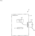
- Fig. 2 is a schematic diagram illustrating a configuration example of the detection device 4.
- a filament 431 is provided as the electron introducer 43 in the detection device 4.
- the filament 431 is provided in a housing 44 formed in a hollow shape. A part of the filament 431 is disposed in the housing 44. The portion of the filament 431 located in the housing 44 is disposed near the detector 42. Current is supplied to the filament 431 with a predetermined current value.
- Fig. 3 is a flowchart illustrating an operation procedure in determining the voltage applied to the detector 42.
- the mass spectrometer 1 performs the operation (applied voltage determination operation) to determine the voltage applied to the detector 42. For example, this operation is performed prior to the analysis operation.
- the current is supplied to the filament 431 with a predetermined current value.
- Thermoelectrons are generated from the filament 431 by thermionic emission (step S101).
- the thermoelectrons generated by the filament 431 are introduced into the detector 42.
- the detector 42 detects the thermoelectrons (electrons) from the filament 431 (step S102), and outputs the detection signal.
- the applied voltage determination unit 61 determines the voltage applied to the detector 42 during the mass spectrometry (step S103). For example, in the case that the detection signal (detection value) from the detector 42 is less than a threshold, the applied voltage determination unit 61 determines the voltage applied to the detector 42 such that the detection signal (detection value) is greater than or equal to the threshold.
- the controller 6 can determine that a defect such as aging is generated in the detector 42.
- the threshold used to determine that the defect is generated in the detector 42 may be a value different from the threshold used to determine the voltage applied to the detector 42.
- the applied voltage determined by the applied voltage determination unit 61 is stored in the storage 5 as the setting value 51 (step S104).
- the voltage controller 62 reads the setting value 51 from the storage 5, and applies the voltage having the value indicated by the setting value 51 to the detector 42. Consequently, the detection value of the detection signal from the detector 42 becomes proper. A sufficient intensity value (peak value) can be obtained in the mass spectrum produced by the mass spectrometer 1.
- the determination that the defect is generated in the mass separator 3 can be made in the case that the detection intensity value of the mass spectrum produced by the mass spectrometer 1 becomes small.
- the mass spectrometer 1 performs the operation (applied voltage determination operation) to determine the voltage applied to the detector 42.
- the controller 6 can determine that the defect such as the aging is generated in the detector 42.
- the mass spectrometer 1 can surely determine the defect of the detector 42.
- the mass spectrometer 1 can determine the defect. For example, in the case that the applied voltage having the value indicated by the setting value 51 is applied to the detector 42, and in the case that the detection intensity value of the mass spectrum becomes small, the determination that the defect is generated in the mass separator 3 (the mass separator 3 or the ionizer 2) can be made.
- the applied voltage determination unit 61 can properly determine the applied voltage.
- the proper detection value can be output from the detector 42 by applying the applied voltage to the detector 42.
- Fig. 4 is a schematic diagram illustrating a configuration example of a detection device 4 of a mass spectrometer 1 according to a second embodiment of the present invention.
- an electrode 433 connected to wirings 432 and 432 is provided as the electron introducer 43 in the detection device 4.
- a part of the wiring 432 is disposed in the housing 44.
- the electrode 433 is provided at a leading end of the wiring 432.
- the electrode 433 is disposed near the detector 42.
- a high voltage is applied to the electrode 433 through the wiring 432. Consequently, electrons are generated at the electrode 433 by field emission. The electrons generated at the electrode 433 are introduced into the detector 42.
- the electrons are generated at the electrode 433 by the field emission, and the electrons are introduced into the detector 42.
- the defect of the detector 42 can surely be determined with a simple configuration in which the wiring 432 and the electrode 433 are provided in the detection device 4 to generate the electrons by the field emission.
- a switching time between an on-state in which the electrons are generated and an off-state in which the electrons are not generated can be shortened because of the configuration in which the wiring 432 and the electrode 433 are provided in the detection device 4 to generate the electrons by the field emission.
- Fig. 5 is a schematic diagram illustrating a configuration example of a detection device 4 of a mass spectrometer 1 according to a third embodiment of the present invention.
- a light source 434 is provided as the electron introducer 43 in the detection device 4.
- the light source 434 is an ultraviolet LED, and is disposed in the housing 44.
- the conversion dynode 41 is irradiated with light emitted from the light source 434. Consequently, the electrons are generated in the conversion dynode 41 by a photoelectric effect.
- the electrons generated by the conversion dynode 41 are introduced into the detector 42.
- the electrons may be generated by irradiating a metal component except for the conversion dynode 41 with light.
- the electrons are generated by the photoelectric effect, and the electrons are introduced into the detector 42.
- the defect of the detector 42 can surely be determined with a simple configuration in which the light source 434 is provided in the detection device 4 to generate the electrons by the photoelectric effect.
- the light source 434 may be provided outside the housing 44, and a window plate may be provided in the housing 44.
- the light from the light source 434 disposed outside the housing 44 may be incident on the housing 44 through the window plate, and the conversion dynode 41 may be irradiated with the light.
- the light source 434 can be disposed outside the housing 44.
- an ion source may be provided near the conversion dynode 41.
- the electrons are generated by converting the ions generated by the ion source using the conversion dynode 41.
- the electrons can be introduced into the detector 42.
Landscapes
- Chemical & Material Sciences (AREA)
- Analytical Chemistry (AREA)
- Other Investigation Or Analysis Of Materials By Electrical Means (AREA)
- Electron Tubes For Measurement (AREA)
Abstract
The mass spectrometer includes an ionizer, a mass separator, a detection device, a storage, and a controller. The detection device includes a detector and an electron introducer. The electrons from the electron introducer are introduced into the detector. In addition to an analysis operation, the mass spectrometer performs an operation to determine a voltage applied to the detector. At this point, electrons are introduced from the electron introducer to the detector. In the case that a detection value from the detector is less than a threshold, the controller can determine that a defect such as aging is generated in the detector.
Description
- The present invention relates to a mass spectrometry detection device that detects ions mass-separated by a mass separator and a mass spectrometer including the mass spectrometry detection device.
- The mass spectrometer includes an ionizer that ionizes a sample, a mass separator that separates ions, and a detection unit that detects the ions discharged from the mass separator.
- For example, the detection unit includes a conversion dynode and an electron multiplier (detector). The ions from the mass separator are converted into electrons by the conversion dynode. The electrons are detected by the electron multiplier. A predetermined voltage is applied to the electron multiplier. For this reason, the electrons are multiplied and detected in the electron multiplier.
- In this way, the electrons are detected in the detection unit. A mass spectrum is produced based on a detection signal from the detection unit (electron multiplier) (for example,
JP-A-2012-122871 - In this way, the detection signal can sufficiently be obtained from the electron multiplier by applying the predetermined voltage to the electron multiplier, and the mass spectrum can be produced based on the detection signal.
- In the conventional mass spectrometer, the voltage applied to the electron multiplier is determined based on a detection intensity value (peak value) indicated by the mass spectrum in performing analysis operation. For example, in the case that the detection intensity value of the mass spectrum is small, a user checks the detection intensity value, and adjusts the applied voltage such that the detection intensity value is increased.
- When the applied voltage is determined for the electron multiplier in this way, whether a cause to decrease the detection intensity value of the mass spectrum is an individual difference or aging of the electron multiplier or a defect of the ionizer or the mass separator cannot be determined. Specifically, even if the individual differences or the aging is generated in the electron multiplier, or even if the defect is generated in the ionizer or the mass separator, the detection intensity value of the mass spectrum is decreased in a similar way, so that the cause cannot be specified.
- The present invention has been made in view of the above circumstances, and an object of the present invention is to provide a mass spectrometry detection device and a mass spectrometer, each being able to surely determine the defect of the detector.
- (1) The present invention provides a mass spectrometry detection device that detects ions mass-separated by a mass separator. The mass spectrometry detection device includes a detector and an electron introducer. The detector detects electrons. The electron introducer is provided separately from the mass separator, and introduces electrons into the detector.
- With this configuration, in the mass spectrometry detection device, the electrons from the electron introducer are introduced into the detector. The defect of the detector can surely be determined when the defect is determined based on intensity (detected value) of the detection signal from the detector at that time.
- For example, the electrons are introduced from the electron introducer to the detector, and the intensity of the detection signal from the detector at that time is less than a threshold. At this point, a determination that the defect such as the aging is generated in the detector can be made.
- As described above, the defect of the detector can surely be determined in the mass spectrometry detection device of the present invention.
- (2) The electron introducer may generate thermoelectrons and introduce the thermoelectrons to the detector.
With this configuration, the defect of the detector can surely be determined with a simple configuration in which the thermoelectrons are generated. - (3) The electron introducer may generate electrons by field emission and introduce the electrons into the detector.
With this configuration, the defect of the detector can surely be determined with a simple configuration in which the electrons are generated by the field emission. - (4) The electron introducer may generate electrons by a photoelectric effect, and introduce the electrons into the detector.
With this configuration, the defect of the detector can surely be determined with a simple configuration in which the electrons are generated by the photoelectric effect. - (5) The present invention provides a mass spectrometer including the mass spectrometry detection device and a mass separator. The mass separator mass-separates ions generated from a sample, and introduces the ions into the mass spectrometry detection device.
With this configuration, the defect of the detector can surely be determined in the mass spectrometer. In the case that the defect is generated in the mass separator (a mechanism except for the detector), the defect can be determined.
For example, in the case that the defect can be determined to be not generated in the detector, and in the case that a detection intensity value of a mass spectrum becomes small, a determination that the defect is generated in the mass separator (the mechanism except for the detector) can be made. - (6) The mass spectrometer may further include an applied voltage determination unit. The applied voltage determination unit determines a voltage applied to the detector during mass spectrometry based on a detection value when the electrons introduced by the electron introducer are detected by the detector.
- With this configuration, in the case that the detection value of the detector is decreased due to the defect such as the aging in the detector, the applied voltage determination unit can properly determine the applied voltage. A proper detection value can be output from the detector by applying the applied voltage to the detector.
- According to the present invention, in the mass spectrometry detection device, the electrons from the electron introducer are introduced into the detector. The defect of the detector can surely be determined when the defect is determined based on intensity of the detection signal from the detector at that time.
-
-
Fig. 1 is a schematic diagram illustrating a configuration example of a mass spectrometer according to a first embodiment of the present invention; -
Fig. 2 is a schematic diagram illustrating a configuration example of a detection device of the mass spectrometer inFig. 1 ; -
Fig. 3 is a flowchart illustrating an operation procedure in determining a voltage applied to a detector; -
Fig. 4 is a schematic diagram illustrating a configuration example of a detection device of a mass spectrometer according to a second embodiment of the present invention; and -
Fig. 5 is a schematic diagram illustrating a configuration example of a detection device of a mass spectrometer according to a third embodiment of the present invention. -
Fig. 1 is a schematic diagram illustrating a configuration example of a mass spectrometer 1 according to a first embodiment of the present invention. - The mass spectrometer 1 includes an
ionizer 2, amass separator 3, a detection device (mass spectrometry detection device) 4, astorage 5, and acontroller 6. - The
ionizer 2 ionizes a target sample. For example, theionizer 2 is a MALDI (matrix-assisted laser desorption ionization) ion source. A sample plate to which a sample adheres and an irradiator (not illustrated) that emits a laser beam toward the sample are provided in the ionizer. Another ion source such as electrospray ionization (ESI) may be used as theionizer 2. - The
mass separator 3 performs mass separation of ions generated from the sample. For example, themass separator 3 is a three-dimensional quadrupole ion trap. An ion trap other than the three-dimensional quadrupole ion trap may be used as themass separator 3. - The
detection device 4 detects mass-separated ions. Thedetection device 4 includes aconversion dynode 41, adetector 42, and an electron introducer 43. - The
conversion dynode 41 converts ions into electrons. - For example, the
detector 42 is an electron multiplier. Thedetector 42 multiplies and detects electrons from theconversion dynode 41. - The
electron introducer 43 generates electrons, and introduces the electrons to thedetector 42. - The
storage 5 is constructed with a ROM (Read Only Memory), a RAM (Random Access Memory), and a hard disk. A settingvalue 51 is stored in thestorage 5. The settingvalue 51 is information about voltage applied to thedetector 42. - For example, the
controller 6 includes a CPU (Central Processing Unit). Thedetector 42 and thestorage 5 are electrically connected to thecontroller 6. The CPU executes a program, which allows thecontroller 6 to function as an appliedvoltage determination unit 61 and avoltage controller 62. - The applied
voltage determination unit 61 determines an applied voltage to thedetector 42 based on a detection signal (detection value) from thedetector 42. The determined applied voltage is stored in thestorage 5 as the settingvalue 51. - The
voltage controller 62 reads the settingvalue 51 of thestorage 5, and applies the voltage to thedetector 42 with a voltage value indicated by the settingvalue 51. - In the case that the sample is analyzed using the mass spectrometer 1, the sample is set in the
ionizer 2. The sample is ionized using theionizer 2. The obtained ions are introduced into themass separator 3 to perform the mass separation. The mass-separated ions are introduced into thedetection device 4. - The ions introduced into the
detection device 4 are converted into the electrons by theconversion dynode 41. The electrons from theconversion dynode 41 are introduced into thedetector 42. The voltage is applied to thedetector 42 with a predetermined voltage value. For this reason, thedetector 42 detects the electrons while the electrons are multiplied. Thecontroller 6 produces a mass spectrum based on the detection signal from thedetector 42. - In addition to the above analysis operation, the mass spectrometer 1 performs an operation to determine the voltage applied to the
detector 42. At this point, as will be described later, the electrons are generated by theelectron introducer 43 and the electrons are introduced into thedetector 42. - The
electron introducer 43 is not limited to a configuration described later, but a member that is normally provided in the mass spectrometer 1 may be used as theelectron introducer 43. For example, a vacuum gauge provided in the mass spectrometer 1 may be used as theelectron introducer 43. In this case, a relative position between the vacuum gauge and thedetector 42 is adjusted such that the electrons generated by the vacuum gauge are introduced into thedetector 42. In this case, preferably the vacuum gauge is turned off during the analysis operation. -
Fig. 2 is a schematic diagram illustrating a configuration example of thedetection device 4. - In the example of
Fig. 2 , afilament 431 is provided as theelectron introducer 43 in thedetection device 4. Specifically, thefilament 431 is provided in ahousing 44 formed in a hollow shape. A part of thefilament 431 is disposed in thehousing 44. The portion of thefilament 431 located in thehousing 44 is disposed near thedetector 42. Current is supplied to thefilament 431 with a predetermined current value. -
Fig. 3 is a flowchart illustrating an operation procedure in determining the voltage applied to thedetector 42. - In addition to the above analysis operation, the mass spectrometer 1 performs the operation (applied voltage determination operation) to determine the voltage applied to the
detector 42. For example, this operation is performed prior to the analysis operation. - Specifically, in the example of
Fig. 3 , the current is supplied to thefilament 431 with a predetermined current value. Thermoelectrons are generated from thefilament 431 by thermionic emission (step S101). The thermoelectrons generated by thefilament 431 are introduced into thedetector 42. Thedetector 42 detects the thermoelectrons (electrons) from the filament 431 (step S102), and outputs the detection signal. - Based on the detection signal (detection value) from the
detector 42, the appliedvoltage determination unit 61 determines the voltage applied to thedetector 42 during the mass spectrometry (step S103). For example, in the case that the detection signal (detection value) from thedetector 42 is less than a threshold, the appliedvoltage determination unit 61 determines the voltage applied to thedetector 42 such that the detection signal (detection value) is greater than or equal to the threshold. - At this point, in the case that the detection signal (detection value) from the
detector 42 is less than the threshold, thecontroller 6 can determine that a defect such as aging is generated in thedetector 42. The threshold used to determine that the defect is generated in thedetector 42 may be a value different from the threshold used to determine the voltage applied to thedetector 42. - The applied voltage determined by the applied
voltage determination unit 61 is stored in thestorage 5 as the setting value 51 (step S104). - In this way, the operation (applied voltage determination operation) to determine the voltage applied to the
detector 42 is completed. - When the mass spectrometer 1 performs the mass spectrometry, the
voltage controller 62 reads the settingvalue 51 from thestorage 5, and applies the voltage having the value indicated by the settingvalue 51 to thedetector 42. Consequently, the detection value of the detection signal from thedetector 42 becomes proper. A sufficient intensity value (peak value) can be obtained in the mass spectrum produced by the mass spectrometer 1. - The determination that the defect is generated in the mass separator 3 (the
mass separator 3 or the ionizer 2) can be made in the case that the detection intensity value of the mass spectrum produced by the mass spectrometer 1 becomes small. -
- (1) In the first embodiment, in the mass spectrometer 1, the
detection device 4 includes thedetector 42 and theelectron introducer 43 as illustrated inFig. 1 . The electrons from theelectron introducer 43 are introduced into thedetector 42. - Specifically, in addition to the analysis operation, the mass spectrometer 1 performs the operation (applied voltage determination operation) to determine the voltage applied to the
detector 42. - At this point, the electrons are introduced from the
electron introducer 43 to thedetector 42. In the case that the detection signal (detection value) from thedetector 42 is less than the threshold, thecontroller 6 can determine that the defect such as the aging is generated in thedetector 42. - That is, the mass spectrometer 1 can surely determine the defect of the
detector 42. - In the case that the defect is generated in the
mass separator 3, the mass spectrometer 1 can determine the defect. For example, in the case that the applied voltage having the value indicated by the settingvalue 51 is applied to thedetector 42, and in the case that the detection intensity value of the mass spectrum becomes small, the determination that the defect is generated in the mass separator 3 (themass separator 3 or the ionizer 2) can be made. - (2) In the present embodiment, the
electron introducer 43 includes thefilament 431 as illustrated inFig. 2 . In thedetection device 4, the current is supplied to thefilament 431 with the predetermined current value, and the thermoelectrons are generated from thefilament 431 by the thermionic emission. The thermoelectrons generated by thefilament 431 are introduced into thedetector 42.
As described above, in the mass spectrometer 1, the defect of thedetector 42 can surely be determined with a simple configuration in which thefilament 431 is provided in thedetection device 4 to generate the thermoelectrons. - (3) In the present embodiment, the mass spectrometer 1 includes the
controller 6. Thecontroller 6 also functions as the appliedvoltage determination unit 61. The appliedvoltage determination unit 61 determines the voltage applied to thedetector 42 during the mass spectrometry based on the detection value when the electrons introduced by the electron introducer 43 (filament 431) are detected by thedetector 42. - For this reason, in the case that the detection value of the
detector 42 is decreased due to the defect such as the aging in thedetector 42, the appliedvoltage determination unit 61 can properly determine the applied voltage. The proper detection value can be output from thedetector 42 by applying the applied voltage to thedetector 42. - Other embodiments of the present invention will be described below with reference to
Figs. 4 and5 . The configuration similar to that of the first embodiment is denoted by the reference numeral similar to that of the first embodiment, and the description is omitted. -
Fig. 4 is a schematic diagram illustrating a configuration example of adetection device 4 of a mass spectrometer 1 according to a second embodiment of the present invention. - In the second embodiment, an
electrode 433 connected to wirings 432 and 432 is provided as theelectron introducer 43 in thedetection device 4. - A part of the
wiring 432 is disposed in thehousing 44. Theelectrode 433 is provided at a leading end of thewiring 432. Theelectrode 433 is disposed near thedetector 42. - In the example of
Fig. 4 , a high voltage is applied to theelectrode 433 through thewiring 432. Consequently, electrons are generated at theelectrode 433 by field emission. The electrons generated at theelectrode 433 are introduced into thedetector 42. - In the second embodiment, in the
detection device 4, the electrons are generated at theelectrode 433 by the field emission, and the electrons are introduced into thedetector 42. - For this reason, the defect of the
detector 42 can surely be determined with a simple configuration in which thewiring 432 and theelectrode 433 are provided in thedetection device 4 to generate the electrons by the field emission. - A switching time between an on-state in which the electrons are generated and an off-state in which the electrons are not generated can be shortened because of the configuration in which the
wiring 432 and theelectrode 433 are provided in thedetection device 4 to generate the electrons by the field emission. -
Fig. 5 is a schematic diagram illustrating a configuration example of adetection device 4 of a mass spectrometer 1 according to a third embodiment of the present invention. - In the third embodiment, a
light source 434 is provided as theelectron introducer 43 in thedetection device 4. - For example, the
light source 434 is an ultraviolet LED, and is disposed in thehousing 44. - In the example of
Fig. 5 , theconversion dynode 41 is irradiated with light emitted from thelight source 434. Consequently, the electrons are generated in theconversion dynode 41 by a photoelectric effect. The electrons generated by theconversion dynode 41 are introduced into thedetector 42. In thelight source 434, the electrons may be generated by irradiating a metal component except for theconversion dynode 41 with light. - As described above, in the third embodiment, in the
detection device 4, the electrons are generated by the photoelectric effect, and the electrons are introduced into thedetector 42. - For this reason, the defect of the
detector 42 can surely be determined with a simple configuration in which thelight source 434 is provided in thedetection device 4 to generate the electrons by the photoelectric effect. - The
light source 434 may be provided outside thehousing 44, and a window plate may be provided in thehousing 44. The light from thelight source 434 disposed outside thehousing 44 may be incident on thehousing 44 through the window plate, and theconversion dynode 41 may be irradiated with the light. - Consequently, the
light source 434 can be disposed outside thehousing 44. - Instead of the
light source 434, an ion source may be provided near theconversion dynode 41. In this case, the electrons are generated by converting the ions generated by the ion source using theconversion dynode 41. The electrons can be introduced into thedetector 42.
Claims (6)
- A mass spectrometry detection device that detects ions mass-separated by a mass separator, the mass spectrometry detection device comprising:a detector that detects electrons; andan electron introducer that is provided separately from the mass separator and introduces electrons into the detector.
- The mass spectrometry detection device according to claim 1, wherein the electron introducer generates thermoelectrons and introduces the thermoelectrons into the detector.
- The mass spectrometry detection device according to claim 1, wherein the electron introducer generates electrons by field emission and introduces the electrons into the detector.
- The mass spectrometry detection device according to claim 1, wherein the electron introducer generates electrons by a photoelectric effect and introduces the electrons into the detector.
- A mass spectrometer comprising:the mass spectrometry detection device according to any one of claims 1 to 4; anda mass separator that mass-separates ions generated from a sample and introduces the mass-separated ions into the mass spectrometry detection device.
- The mass spectrometer according to claim 5, further comprising an applied voltage determination unit that determines a voltage applied to the detector during mass spectrometry, based on a detection value when the electrons introduced by the electron introducer are detected by the detector.
Applications Claiming Priority (1)
| Application Number | Priority Date | Filing Date | Title |
|---|---|---|---|
| JP2018099701A JP2019204708A (en) | 2018-05-24 | 2018-05-24 | Mass spectrometric detection device and mass spectrometer |
Publications (1)
| Publication Number | Publication Date |
|---|---|
| EP3573087A1 true EP3573087A1 (en) | 2019-11-27 |
Family
ID=66625023
Family Applications (1)
| Application Number | Title | Priority Date | Filing Date |
|---|---|---|---|
| EP19175252.6A Withdrawn EP3573087A1 (en) | 2018-05-24 | 2019-05-17 | Mass spectrometry detection device and mass spectrometer |
Country Status (3)
| Country | Link |
|---|---|
| US (1) | US11164732B2 (en) |
| EP (1) | EP3573087A1 (en) |
| JP (1) | JP2019204708A (en) |
Cited By (1)
| Publication number | Priority date | Publication date | Assignee | Title |
|---|---|---|---|---|
| EP3752825A4 (en) * | 2018-02-13 | 2021-11-24 | bioMérieux, Inc. | METHODS FOR TESTING OR ADJUSTING A CHARGED PARTICLE DETECTOR, AND ASSOCIATED DETECTION SYSTEMS |
Families Citing this family (1)
| Publication number | Priority date | Publication date | Assignee | Title |
|---|---|---|---|---|
| US10672597B2 (en) | 2018-07-11 | 2020-06-02 | Thermo Finnigan Llc | Calibrating electron multiplier gain using the photoelectric effect |
Citations (6)
| Publication number | Priority date | Publication date | Assignee | Title |
|---|---|---|---|---|
| US3317823A (en) * | 1963-04-08 | 1967-05-02 | United States Atomic Energy Commission | Self-checking ionization chamber type radiation detector |
| EP0310210A1 (en) * | 1983-03-04 | 1989-04-05 | UTI Instruments Company | Measuring trace elements in gas |
| WO1994001206A1 (en) * | 1992-07-02 | 1994-01-20 | Arch Development Corporation | Time-of-flight direct recoil ion scattering spectrometer |
| US20050199793A1 (en) * | 2002-04-23 | 2005-09-15 | Siemens Plc | Radiation detector including means for indicating satisfactory operation |
| US7157681B1 (en) * | 2003-12-16 | 2007-01-02 | Wolfgang Tetzlaff | Photomultiplier tube gain stabilization for radiation dosimetry system |
| JP2012122871A (en) | 2010-12-09 | 2012-06-28 | Shimadzu Corp | Mass analysis method and apparatus |
Family Cites Families (11)
| Publication number | Priority date | Publication date | Assignee | Title |
|---|---|---|---|---|
| US2959676A (en) * | 1957-07-29 | 1960-11-08 | Phillips Petroleum Co | Mass spectrometer |
| DE4019005C2 (en) * | 1990-06-13 | 2000-03-09 | Finnigan Mat Gmbh | Devices for analyzing high mass ions |
| JP3937127B2 (en) * | 2001-02-20 | 2007-06-27 | 信越化学工業株式会社 | Optical fiber manufacturing method |
| US8829428B2 (en) * | 2009-11-30 | 2014-09-09 | Ionwerks, Inc. | Time-of-flight spectrometry and spectroscopy of surfaces |
| EP2798662A4 (en) * | 2011-12-27 | 2015-09-23 | Dh Technologies Dev Pte Ltd | Ultrafast transimpedance amplifier interfacing electron multipliers for pulse counting applications |
| US10153059B2 (en) * | 2012-02-24 | 2018-12-11 | The Regents Of The University Of California | Charged particle acceleration device |
| US9316625B2 (en) * | 2012-09-20 | 2016-04-19 | Shimadzu Corporation | Mass spectrometer |
| CN108597980B (en) * | 2013-08-13 | 2020-05-08 | 普度研究基金会 | Sample quantification using a miniature mass spectrometer |
| US9847214B2 (en) * | 2013-11-26 | 2017-12-19 | Perkinelmer Health Sciences, Inc. | Detectors and methods of using them |
| US9508534B2 (en) * | 2014-11-07 | 2016-11-29 | Thermo Finnigan Llc | Systems and methods for calibrating gain in an electron multiplier |
| US9899197B2 (en) * | 2015-09-01 | 2018-02-20 | The United States Of America, As Represented By The Secretary Of Commerce | Hybrid extreme ultraviolet imaging spectrometer |
-
2018
- 2018-05-24 JP JP2018099701A patent/JP2019204708A/en active Pending
-
2019
- 2019-03-06 US US16/294,186 patent/US11164732B2/en not_active Expired - Fee Related
- 2019-05-17 EP EP19175252.6A patent/EP3573087A1/en not_active Withdrawn
Patent Citations (6)
| Publication number | Priority date | Publication date | Assignee | Title |
|---|---|---|---|---|
| US3317823A (en) * | 1963-04-08 | 1967-05-02 | United States Atomic Energy Commission | Self-checking ionization chamber type radiation detector |
| EP0310210A1 (en) * | 1983-03-04 | 1989-04-05 | UTI Instruments Company | Measuring trace elements in gas |
| WO1994001206A1 (en) * | 1992-07-02 | 1994-01-20 | Arch Development Corporation | Time-of-flight direct recoil ion scattering spectrometer |
| US20050199793A1 (en) * | 2002-04-23 | 2005-09-15 | Siemens Plc | Radiation detector including means for indicating satisfactory operation |
| US7157681B1 (en) * | 2003-12-16 | 2007-01-02 | Wolfgang Tetzlaff | Photomultiplier tube gain stabilization for radiation dosimetry system |
| JP2012122871A (en) | 2010-12-09 | 2012-06-28 | Shimadzu Corp | Mass analysis method and apparatus |
Cited By (1)
| Publication number | Priority date | Publication date | Assignee | Title |
|---|---|---|---|---|
| EP3752825A4 (en) * | 2018-02-13 | 2021-11-24 | bioMérieux, Inc. | METHODS FOR TESTING OR ADJUSTING A CHARGED PARTICLE DETECTOR, AND ASSOCIATED DETECTION SYSTEMS |
Also Published As
| Publication number | Publication date |
|---|---|
| US11164732B2 (en) | 2021-11-02 |
| US20190362954A1 (en) | 2019-11-28 |
| JP2019204708A (en) | 2019-11-28 |
Similar Documents
| Publication | Publication Date | Title |
|---|---|---|
| JP4922940B2 (en) | Ion detection in mass spectrometry with extended dynamic range | |
| US7291845B2 (en) | Method for controlling space charge-driven ion instabilities in electron impact ion sources | |
| JP5107263B2 (en) | Ion fragmentation in a mass spectrometer. | |
| US9543138B2 (en) | Ion optical system for MALDI-TOF mass spectrometer | |
| US9035244B2 (en) | Automatic gain control with defocusing lens | |
| US20160172146A1 (en) | Ion source for soft electron ionization and related systems and methods | |
| US8735810B1 (en) | Time-of-flight mass spectrometer with ion source and ion detector electrically connected | |
| JP6773236B2 (en) | Mass spectrometer and mass spectrometry method | |
| US11848181B2 (en) | Acquisition strategy for top-down analysis with reduced background and peak overlapping | |
| JP2015514300A5 (en) | ||
| US11996277B2 (en) | Method of gain calibration | |
| US11164732B2 (en) | Mass spectrometry detection device and mass spectrometer | |
| WO2010049973A1 (en) | Mass spectrometry | |
| JP5472068B2 (en) | Mass spectrometry method and apparatus | |
| KR20150065493A (en) | Apparatus for Acquiring Ion source of Mass spectrometry using MCP and CEM | |
| JP2011175897A (en) | Mass spectrometer | |
| WO2014149847A2 (en) | Ionization within ion trap using photoionization and electron ionization | |
| US8927943B2 (en) | Device for obtaining the ion source of a mass spectrometer using an ultraviolet diode and a CEM | |
| JP2002260573A (en) | Mass spectrometer | |
| EP3965140B1 (en) | Long life electron multiplier | |
| TWI895299B (en) | Quadrupole mass spectrometer, quadrupole mass spectrometry method, and program storage medium storing program for quadrupole mass spectrometer | |
| US11201047B2 (en) | Time-of-flight mass spectrometer | |
| JP2018077180A (en) | SPECTRUM OPERATION PROCESSING DEVICE, SPECTRUM OPERATION PROCESSING METHOD, MASS ANALYZER, AND MASS ANALYSIS METHOD | |
| US10923337B2 (en) | Ion trap mass spectrometer and ion trap mass spectrometry method | |
| JPH05325886A (en) | Mass spectrometry device |
Legal Events
| Date | Code | Title | Description |
|---|---|---|---|
| PUAI | Public reference made under article 153(3) epc to a published international application that has entered the european phase |
Free format text: ORIGINAL CODE: 0009012 |
|
| 17P | Request for examination filed |
Effective date: 20190517 |
|
| AK | Designated contracting states |
Kind code of ref document: A1 Designated state(s): AL AT BE BG CH CY CZ DE DK EE ES FI FR GB GR HR HU IE IS IT LI LT LU LV MC MK MT NL NO PL PT RO RS SE SI SK SM TR |
|
| AX | Request for extension of the european patent |
Extension state: BA ME |
|
| STAA | Information on the status of an ep patent application or granted ep patent |
Free format text: STATUS: THE APPLICATION HAS BEEN WITHDRAWN |
|
| 18W | Application withdrawn |
Effective date: 20200602 |