EP3573055B1 - Multi-channel decoder - Google Patents
Multi-channel decoder Download PDFInfo
- Publication number
- EP3573055B1 EP3573055B1 EP19178839.7A EP19178839A EP3573055B1 EP 3573055 B1 EP3573055 B1 EP 3573055B1 EP 19178839 A EP19178839 A EP 19178839A EP 3573055 B1 EP3573055 B1 EP 3573055B1
- Authority
- EP
- European Patent Office
- Prior art keywords
- encoder
- decoder
- channel
- data
- channels
- Prior art date
- Legal status (The legal status is an assumption and is not a legal conclusion. Google has not performed a legal analysis and makes no representation as to the accuracy of the status listed.)
- Expired - Lifetime
Links
Images

Classifications
-
- G—PHYSICS
- G10—MUSICAL INSTRUMENTS; ACOUSTICS
- G10L—SPEECH ANALYSIS TECHNIQUES OR SPEECH SYNTHESIS; SPEECH RECOGNITION; SPEECH OR VOICE PROCESSING TECHNIQUES; SPEECH OR AUDIO CODING OR DECODING
- G10L19/00—Speech or audio signals analysis-synthesis techniques for redundancy reduction, e.g. in vocoders; Coding or decoding of speech or audio signals, using source filter models or psychoacoustic analysis
- G10L19/008—Multichannel audio signal coding or decoding using interchannel correlation to reduce redundancy, e.g. joint-stereo, intensity-coding or matrixing
-
- G—PHYSICS
- G10—MUSICAL INSTRUMENTS; ACOUSTICS
- G10L—SPEECH ANALYSIS TECHNIQUES OR SPEECH SYNTHESIS; SPEECH RECOGNITION; SPEECH OR VOICE PROCESSING TECHNIQUES; SPEECH OR AUDIO CODING OR DECODING
- G10L19/00—Speech or audio signals analysis-synthesis techniques for redundancy reduction, e.g. in vocoders; Coding or decoding of speech or audio signals, using source filter models or psychoacoustic analysis
- G10L19/02—Speech or audio signals analysis-synthesis techniques for redundancy reduction, e.g. in vocoders; Coding or decoding of speech or audio signals, using source filter models or psychoacoustic analysis using spectral analysis, e.g. transform vocoders or subband vocoders
-
- G—PHYSICS
- G10—MUSICAL INSTRUMENTS; ACOUSTICS
- G10L—SPEECH ANALYSIS TECHNIQUES OR SPEECH SYNTHESIS; SPEECH RECOGNITION; SPEECH OR VOICE PROCESSING TECHNIQUES; SPEECH OR AUDIO CODING OR DECODING
- G10L19/00—Speech or audio signals analysis-synthesis techniques for redundancy reduction, e.g. in vocoders; Coding or decoding of speech or audio signals, using source filter models or psychoacoustic analysis
- G10L19/02—Speech or audio signals analysis-synthesis techniques for redundancy reduction, e.g. in vocoders; Coding or decoding of speech or audio signals, using source filter models or psychoacoustic analysis using spectral analysis, e.g. transform vocoders or subband vocoders
- G10L19/0204—Speech or audio signals analysis-synthesis techniques for redundancy reduction, e.g. in vocoders; Coding or decoding of speech or audio signals, using source filter models or psychoacoustic analysis using spectral analysis, e.g. transform vocoders or subband vocoders using subband decomposition
-
- H—ELECTRICITY
- H04—ELECTRIC COMMUNICATION TECHNIQUE
- H04S—STEREOPHONIC SYSTEMS
- H04S3/00—Systems employing more than two channels, e.g. quadraphonic
-
- H—ELECTRICITY
- H04—ELECTRIC COMMUNICATION TECHNIQUE
- H04S—STEREOPHONIC SYSTEMS
- H04S3/00—Systems employing more than two channels, e.g. quadraphonic
- H04S3/008—Systems employing more than two channels, e.g. quadraphonic in which the audio signals are in digital form, i.e. employing more than two discrete digital channels
Definitions
- the six original input signals denoted by 400 to 450 comprise: a left front audio signal 400, a left rear audio signal 410, an effects audio signal 420, a center audio signal 430, a rear front audio signal 440 and a right rear audio signal 450.
- the effects signal 420 preferably has a bandwidth of substantially 120 Hz for use in simulating rumble, explosion and thunder effects for example.
- the input signals 400, 410, 430, 440, 450 preferably correspond to 5-channel home movie sound channels.
- the processing units 20, 30, 40 are preferably implemented in a manner elucidated in published European patent application no. EP1107232-A2 with regard to these units 20, 30, 40.
- the input signals CH1 to CH3 are processed in the channel unit 100, 200, 300 to yield a representation of the input signals in time/frequency tiles. Processing operations as depicted by Equations 1 to 13 are repeated for each of these tiles.
- the signals Lo[k] of all frequency tiles are combined in the encoder 5 and transformed to the time domain to form a signal for the current segment and this signal is at least partially combined with the signal pertaining to at least a preceding segment thereto to generate the encoded output signal 620.
- the signals R o [k] are processed in a similar manner to the signals L o [k] to generate the encoded output signal 610.
- the decoder 18 comprises a segment and transform unit 1600 for transforming the aforementioned down-mix outputs 610, 620 denoted by r o , l o to generate corresponding transformed signals 1650, 1660 denoted by R o , L o respectively.
- the decoder 18 also includes a decoding processor 1610 for receiving the signals 600, 1650, 1660 and processing them to generate corresponding processed signals 1700, 1710, 1720 relating to left-channel (L), center channel (C) and right-channel (R) respectively.
- the signal 1710 is coupled directly and also via a decorrelator 1760 as shown to an inverse PCA unit 1810 which is operable to generate two intermediate outputs Cs, LFE which are coupled to an inverse transform unit 1910.
- the inverse transform unit 1910 is operable to process the intermediate outputs Cs, LFE to generate decoder outputs 2020, 2030 corresponding to the output 1510 in Figure 2 , namely regenerated versions of the input signals 420, 430.
- Processing operations executed within the decoding processor 1610 also known as a decoder according to the invention, involve mathematical operations as described in the foregoing with reference to the decoder 10 illustrated in Figure 2 .
- N 3 hence only two parameters per tile, as determined by 2N-4, need to be transmitted from the encoder 5 to the decoder 10.
- Such an arrangement is of advantage in that the two parameters or coefficients C 1, Z i and C 2, Z i are nominally in a similar numerical range such that similar quantization can be applied to them.
- each tile when providing three or more channel playback, there are computed for each tile six parameters, namely C 1,L , C 2,L , C 1,R , C 2,R , C 1,Cs and C 2,Cs .
- Such computation is based on two transmitted parameters and information regarding relations between these six parameters.
- the coefficients C 1,L and C 2,R are transmitted from the encoder 5 to the decoder 10.
- signals R ⁇ [ k ] and ⁇ s [ k ] are then transformable from the frequency domain to the temporal domain to generate signals 1500 to 1520 for output from the decoder 10 for user appreciation, for example during home movie presentation.
Landscapes
- Engineering & Computer Science (AREA)
- Physics & Mathematics (AREA)
- Signal Processing (AREA)
- Acoustics & Sound (AREA)
- Audiology, Speech & Language Pathology (AREA)
- Health & Medical Sciences (AREA)
- Computational Linguistics (AREA)
- Human Computer Interaction (AREA)
- Multimedia (AREA)
- Spectroscopy & Molecular Physics (AREA)
- Mathematical Physics (AREA)
- Compression, Expansion, Code Conversion, And Decoders (AREA)
- Stereophonic System (AREA)
- Compression Or Coding Systems Of Tv Signals (AREA)
Description
- The present invention relates to multi-channel decoders, for example multi-channel audio decoders utilizing parametric descriptions of spatial audio. Moreover, the invention also relates to methods of processing signals, for example spatial audio, in such multi-channel decoders.
- Audio recording and reproduction has in recent years progressed from monaural single-channel format to dual-channel stereo format and more recently to multi-channel format, for example five-channel audio format as often used in home movie systems. The introduction of super audio compact disks (SACD) and digital video disc (DVD) data carriers has resulted in such five-channel audio reproduction contemporarily gaining interest. Many users presently own equipment capable of providing five-channel audio playback in their homes; correspondingly, five-channel audio programme content on suitable data carriers is becoming increasingly available, for example the aforementioned SACD and DVD types of data carriers. On account of growing interest in multi-channel programme content, more efficient coding of multi-channel audio programme content is becoming an important issue, for example to provide one or more of enhanced quality, longer playing time and even more channels. Moreover, this growing interest has prompted standardization bodies such as MPEG to appreciate that design of multi-channel encoders is a relevant topic.
- Encoders capable of representing spatial audio information such as audio programme content by way of parametric descriptors are known. For example, in a published international PCT patent application no.
PCT/IB2003/002858 WO 2004/008805 ), encoding of a multi-channel audio signal including at least a first signal component (LF), a second signal component (LR) and a third signal component (RF) is described. This encoding utilizes a method comprising steps of: - (a) encoding the first and second signal components by using a first parametric encoder for generating a first encoded signal (L) and a first set of encoding parameters (P2);
- (b) encoding the first encoded signal (L) and a further signal (R) by using a second parametric encoder for generating a second encoded signal (T) and a second set of encoding parameters (P1) wherein the further signal (R) is derived from at least the third signal component (RF); and
- (c) representing the multi-channel audio signal at least by a resulting encoded signal (T) derived from at least the second encoded signal (T), the first set of encoding parameters (P2) and the second set of encoding parameters (P1).
- The article "Intra-channel Prediction: A New Tool for the Subband Coding of High Quality Audio" by G. Dimino, Audio Engineering Society Preprint 4198, 1 January 1996, XP055359830 discloses the use of a forward adaptive linear predictor being applied to a MPEG-2 Layer II coding system to reduce the intra-channel correlation in the presence of musical items.
- Parametric descriptions of audio signals have gained interest in recent years because it has been shown that transmitting quantized parameters describing audio signals requires relative little transmission capacity. These quantized parameters are capable of being received and processed in decoders to regenerate audio signals perceptually not significantly differing from their corresponding original audio signals.
- A problem of significant inter-channel interference arises when output from contemporary multi-channel encoders is subsequently decoded. Such interference is especially noticeable in multi-channel encoders arranged to yield a good stereo image in association with two-channel down-mix. The present invention is arranged to at least partially address this problem, thereby enhancing the quality of corresponding decoded multi-channel audio.
- According to a first aspect of the present invention, there is provided a multi-channel decoder in accordance with claim 1. According to another aspect of the invention, there is provided a method of decoding encoded data in accordance with claim 2.
- Embodiments of the invention will now be described, by way of example only, with reference to the following diagrams wherein:
-
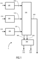
Fig. 1 is a schematic block diagram of an embodiment of a multi-channel encoder including therein a coder not falling within the scope of the invention; and -
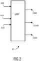
Fig. 2 is a schematic block diagram of an embodiment of a decoder according to the invention compatible with the encoder ofFigure 1 ; -
Fig. 3 shows a coder employed within a multi-channel encoder and not falling within the scope of the invention; -
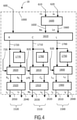
Fig. 4 is an embodiment of a decoder according to the invention, using the coder compatible with the encoder ofFig. 3 ; and -
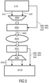
Fig. 5 is a configuration where a multi-channel encoder and a multi-channel decoder according to the invention are mutually configured with a standard stereo encoder and decoder. - In a first context, the following description is concerned with an encoder which is operable to process original input signals to generate corresponding encoded output data capable on being subsequent decoded in a decoder to regenerate perceptually more precise representations of the original input signals than hitherto possible. In a second context, the following description is concerned with specific examples.
- The first context will now be considered with regard to
Figures 1 and2 . In overview, the present invention is concerned with an encoder indicated generally by 5 inFigure 1 . Theencoder 5 includes N input channels for receiving corresponding original input signals; for example, the encoder includes three input channels CH1, CH2, CH3 when N = 3. Theencoder 5 is operable to process the original input signals of the N channels to generate: - (a) corresponding encoded output signals at M down-mix channel outputs where M<N, for example two channel outputs OP1 and OP2 denoted by 610, 620 respectively when M = 2; and
- (b) one or more parametric signal outputs, for example a parametric output denoted by 600.
- In order subsequently to most optimally decode in a decoder output signals generated by the
encoder 5, namely with regard to least-squares-errors, it is contemporarily beneficial that Principal Component Analysis (PCA) be employed in theencoder 5 when generating its encodedoutput signals output signals Figure 2 corresponding to the N input signals presented to theencoder 5 is potentially possible if parameters generated by PCA of theencoder 5 are taken into account. Values for PCA parameters in thesignals encoder 5. Such lack of control renders it contemporarily substantially impossible to obtain a satisfactory stereo image quality when PCA is employed in theencoder 5 and itscorresponding decoder 10. - The inventors have appreciated for the present invention that, when a fixed down-mix is employed in conjunction with the aforementioned M down-mix channels in the
encoder 5, a substantially perfect regeneration of the original input signals at thecomplementary decoder 10 is potentially possible when these M down-mix channels are extended by way of an additional appropriate set of N-M channels conveying complementary information. Thus, output signals of M down-mix channels generated by a fixed down-mix cannot be used to regenerate substantially perfect representations of original input signals of N channels when information relating to such N-M channels has been at least partially discarded during encoding. However, the inventors have appreciated that these N-M channels can at least partially be predicted when suitable processing is applied to the M down-mix channels, for example to theoutputs - Thus, an
encoder 5 predicts from the M down-mix channels at least some information corresponding to the N-M channels at a decoder, while at the same time avoiding a need to send certain parameters from theencoder 5 to thedecoder 10. Such prediction makes use of signal redundancy occurring between signals of the N channels as will be described in more detail later. Moreover, the correspondinglycompatible decoder 10 reinstates the redundancy when decoding encoded data provided from theencoder 5. - In order to further elucidate the present invention, an example of the
encoder 5 illustrated inFigure 1 will be described and then a method of signal processing employed therein will be presented with reference to its mathematical basis. - The example pursuant to the aforementioned second context will now be described with reference to
Figures 3 and4 . - In
Figure 3 , there is shown a multi-channel encoder indicated generally by 15. Theencoder 15 includes threeprocessing units processing units aforementioned N channels 500 to 520 described with reference to theencoder 5. Theencoder 15 also comprises a mixing andparameter extraction unit 180 for receiving processedoutputs processing units extraction unit 180 comprise the aforementioned third parameter setoutput 600, and left and rightintermediate signals inverse transform unit 360 to generate the aforesaid down-mix outputs Parameter output sets mix outputs encoder 15 suitable for being subsequently communicated to a corresponding compatible decoder whereat the output data is decoded to regenerate representations of one or more of the sixinput signals 400 to 450. Alternatively, the down-mix outputs - The six original input signals denoted by 400 to 450 comprise: a left
front audio signal 400, a leftrear audio signal 410, aneffects audio signal 420, acenter audio signal 430, a rearfront audio signal 440 and a rightrear audio signal 450. Theeffects signal 420 preferably has a bandwidth of substantially 120 Hz for use in simulating rumble, explosion and thunder effects for example. Moreover, theinput signals - The
processing units EP1107232-A2 with regard to theseunits - The
processing unit 20 comprises a segment and transformunit 100, aparameter analysis unit 110, a parameter toPCA angle unit 120 and aPCA rotation unit 130. Thetransform unit 100 includes transformed left-front and left-rear outputs PCA rotation unit 130 and theparameter analysis unit 110. A firstparameter set output 720 is coupled via thePCA angle unit 120 to thePCA rotation unit 120. Therotation unit 120 is operable to process theoutputs output 500. Processing within theunit 20 is performed on the basis of time/frequency tiles. - Similarly, the
processing unit 30 comprises a segment and transformunit 200, aparameter analysis unit 210, a parameter toPCA angle unit 220 and aPCA rotation unit 230. Thetransform unit 200 includes transformed left-front and left-rear outputs PCA rotation unit 230 and theparameter analysis unit 210. A fourthparameter set output 820 is coupled via thePCA angle unit 220 to thePCA rotation unit 220. Therotation unit 220 is operable to process theoutputs output 510. Processing within theunit 30 is also performed on the basis of time/frequency tiles. - Similarly, the
processing unit 40 comprises a segment and transformunit 300, aparameter analysis unit 310, a parameter toPCA angle unit 320 and aPCA rotation unit 330. Thetransform unit 300 includes transformed left-front and left-rear outputs PCA rotation unit 330 and theparameter analysis unit 310. A secondparameter set output 920 is coupled via thePCA angle unit 320 to thePCA rotation unit 320. Therotation unit 320 is operable to process theoutputs output 520. Processing within theunit 40 is performed on the basis of time/frequency tiles. - The processed
outputs mix outputs parameter set output 600 includes additional parameter data which can be processed at a decoder, for example thedecoder 10 illustrated inFigure 2 , together with the output parameter sets 720, 820, 920 and the down-mix outputs input signals 400 to 450. A manner in which this down-mix occurs to produce the down-mix outputs parameter set output 600 will next be described. - Referring again to the first context with regard to
Figures 1 and2 , the original input signals of N channels CH1 to CH3, namely z1[n], z2[n],..., zN[n], describe discrete time-domain waveforms of the N channels. These signals z1[n] to zN[n] are segmented in the threeprocessing units - For convenience, we consider two down-mix channels as illustrated for the
encoder 15, although extension to other numbers of down-mix channels is possible. From the original input signals conveyed in N channels CH1 to CH3, theencoder 5 processes the aforesaid sub-band representations Z1[k] to ZN[k] to generate two down-mix channels Lo[k] and Ro[k] as provided in Equations 1 and 2 (Eq. 1 and 2):

decoder 10 regenerating representations of the original input signals for CH1 to CH3 is only capable of generating substantially perfect representations when the two down-mix channels Lo[k] and Ro[k] are supplemented with an appropriate set of parameters to substantially regenerate the N-2 missing channels. When fixed down-mixing is employed, to some extent, information of the N-2 discarded channels can be predicted from the two down-mix channels Lo[k] and Ro[k], thereby providing a way of enhancing accuracy of regeneration of the aforesaid representation of the original input signals of channels CH1 to CH3 at a corresponding decoder, for example thedecoder 10. - In a situation where information relating to certain of the N channels is discarded in generating the output signals 600, 610, 620, namely the discarded channels are denoted by C0,i[k], these discarded channels can be predicted from the down-mix channels Lo[k] and Ro[k] by applying Equation 3 (Eq. 3):

encoder 5 is a minimum Euclidean norm of the signal C0,i [k] and its estimation Ĉ0,i [k]. In order to allow for processing according to Equation 3 to be employed in a decoder complementary to theencoder 5, the parameters C̃1,i and C̃2,i are preferably included in the third parameter set 600 output from theencoder 5. - The inventors have appreciated that the parameters C̃1,i and C̃2,i in Equation 3 are related to parameters that are generated in the
encoder 5 when minimizing the Euclidean norm of the difference of the signal Zi[k] and an estimation Ẑi [k] thereof generated at thedecoder 10. Theencoder 5 preferably is configured to employ these latter parameters Zi[k], Ẑi [k]. A square of the Euclidean norm of the difference of the original input signal Zi[k] is then calculable in theencoder 5 by applying Equation 4 (Eq. 4):


- Thus, for the parameters C 1,Zi and C 2,Zi as calculable from Equations 6 and 7, the following relationships are derivable from
Equations 10 to 13 (Eq. 10 to 13) with regard to coefficients αi and βi, for example as relevant to Equations 1 and 2 (Eq. 1 and 2):


- Thus, in the
encoder 5, applying processing operations as described by Equations 1 to 13 (Eq. 1 to 13), it is feasible to convert input signals corresponding to N channels, namely the input signals for CH1 to CH3 wherein N = 3, with two parameters per channel and two down-mix channels to generate signals for theoutputs parameter set output 600; the two parameters for the i-th channel are C 1, Zi and C 2,Zi . If the down-mix is fixed for every time/frequency tile, the down-mix is known at thedecoder 10, so that the relations between the parameters are a priori known. If, on the other hand, it is chosen to vary the down-mix, information regarding the actual down-mix has to be sent to thedecoder 10. - In the
encoder 5, the input signals CH1 to CH3 are processed in thechannel unit encoder 5 and transformed to the time domain to form a signal for the current segment and this signal is at least partially combined with the signal pertaining to at least a preceding segment thereto to generate the encodedoutput signal 620. The signals Ro[k] are processed in a similar manner to the signals Lo[k] to generate the encodedoutput signal 610. - In summary, the
encoder 5, and similarly theencoder 15 is operable to encode the three input signals CH1 to CH3 as two down-mixed channels - Complementary to the
encoder 5 illustrated inFigure 1 , similarly theencoder 15 illustrated inFigure 3 , is a complementary decoder presented schematically inFigure 2 and indicated therein generally by 10. Thedecoder 10 includes aprocessing unit 1000 which is operable to receive the down-mix output signals 610, 620 from theencoder 5 and also the thirdparameter set output 600 conveying parametric information, for example values for the aforementioned parameters C 1,Zi and C 2, Zi . Thedecoder 10 is operable to process signals from theoutputs output signals - At the
decoder 10, when receiving theoutputs encoder 5, for example conveyed by way of a communication network such as the Internet and/or a data carrier such as a digital video disk (DVD) or similar data medium, for each time/frequency tile, the following processing functions are performed: - (a) the coefficients C 1,Zi and C 2,Zi are computed for all N channels using the 2N-4 coefficients and the four equations, namely information pertaining to
Equations 10 to 13, describing relationships between the coefficients; and then - (b) an approximate representation Ẑi [k] of each input signal Z1[k] is computed using Equation 14 (Eq. 14):
- A specific example embodiment of the
decoder 10 illustrated inFigure 2 in the first context will now be described with reference toFigure 4 in the second context. InFigure 4 , there is shown a decoder indicated generally by 18. Thedecoder 18 comprises a segment and transformunit 1600 for transforming the aforementioned down-mix outputs signals decoder 18 also includes adecoding processor 1610 for receiving thesignals signals - The
signal 1700 is coupled directly and also via adecorrelator 1750 as shown to aninverse PCA unit 1800 which is operable to generate two intermediate outputs Lf, Ls which are coupled to aninverse transform unit 1900. Theinverse transform unit 1900 is operable to process the intermediate outputs Lf, Ls to generatedecoder outputs output 1500 inFigure 2 , namely regenerated versions of the input signals 400, 410. - Similarly, the
signal 1710 is coupled directly and also via adecorrelator 1760 as shown to aninverse PCA unit 1810 which is operable to generate two intermediate outputs Cs, LFE which are coupled to aninverse transform unit 1910. Theinverse transform unit 1910 is operable to process the intermediate outputs Cs, LFE to generatedecoder outputs output 1510 inFigure 2 , namely regenerated versions of the input signals 420, 430. - Similarly, the
signal 1720 is coupled directly and also via adecorrelator 1770 as shown to aninverse PCA unit 1820 which is operable to generate two intermediate outputs Rf, Rs which are coupled to aninverse transform unit 1920. Theinverse transform unit 1920 is operable to process the intermediate outputs Rf, Rs to generatedecoder outputs output 1520 inFigure 2 , namely regenerated versions of the input signals 440, 450. - The
units parameter inputs - Processing operations executed within the
decoding processor 1610, also known as a decoder according to the invention, involve mathematical operations as described in the foregoing with reference to thedecoder 10 illustrated inFigure 2 . - For example, the
encoder 5, similarly theencoder 15, is preferably arranged to function so as to generate a good stereo image in the down-mix outputs by applyingEquations 15 and 16 (Eq. 15 and 16) during processing:

- In such a situation N = 3 hence only two parameters per tile, as determined by 2N-4, need to be transmitted from the
encoder 5 to thedecoder 10. Such an arrangement is of advantage in that the two parameters or coefficients C 1,Zi and C 2,Zi are nominally in a similar numerical range such that similar quantization can be applied to them. - Correspondingly, at the
decoder 10, when providing three or more channel playback, there are computed for each tile six parameters, namely C1,L, C2,L, C1,R, C2,R, C1,Cs and C2,Cs. Such computation is based on two transmitted parameters and information regarding relations between these six parameters. - As an example, the coefficients C1,L and C2,R are transmitted from the
encoder 5 to thedecoder 10. According to the invention, thedecoder 10 derives other coefficients therefrom by way of Equations 17 (Eqs. 17), namely:
- When these six coefficients have been derived for each tile, representations of output signals within the
encoder 5, namely L̂[k], and Ĉs[k], are regenerated within thedecoder 10 by using Equation 18 (Eq. 18) in computations executed within the decoder 10:
- These signals R̂[k] and Ĉs[k] are then transformable from the frequency domain to the temporal domain to generate
signals 1500 to 1520 for output from thedecoder 10 for user appreciation, for example during home movie presentation. - In a most straightforward use of the
multi-channel encoders multi-channel encoder multi-channel decoder Figures 3 and4 , the output signals 610, 620 ofFigure 3 are directly fed to astandard stereo encoder 3000 and thereafter via amultiplexer 3002 as depicted inFigure 5 .Outputs 3005 of themultiplexer 3002 which include parameter data (600; 600, 720, 820, 920) are then subsequently conveyed via adata communication route 3010, for example via a data carrier or communication network, to ademultiplexer 3012 and thereafter to astereo decoder 3020 complementary to thestereo encoder 3000.Decoded output signals 3030 from thedecoder 3020 together with the parameter data (600; 600, 720, 820, 920) from thedemultiplexer 3012 are fed to themulti-channel decoder outputs 3030 of thedecoder 3020 are regenerated versions of the output signals 610, 620 from themulti-channel encoders Figure 5 is an example of a manner in which themulti-channel encoders multi-channels decoders - Expressions such as "comprise", "include", "incorporate", "contain", "is" and "have" are to be construed in a non-exclusive manner when interpreting the description and its associated claims, namely construed to allow for other items or components which are not explicitly defined also to be present. Reference to the singular is also to be construed to be a reference to the plural and vice versa.

Claims (2)
- A multi-channel decoder (10; 18) for decoding encoded data generated by a multi-channel encoder (5; 15), the encoded data comprising down-mix signals (610, 620) for a plurality of input channels (CH1 to CH3; 400 to 450) together with parametric data (600) ; the decoder (10; 18) comprising:(a) processing means for receiving the down-mix signals (610, 620) together with the parametric data (600) from the encoder (5; 15), the processing means being operable to process the parametric data to determine one or more coefficients including a first coefficient C1,L and a second coefficient C2,R; and(b) computing means for calculating an approximate representation of each input channel encoded into the encoded data using the parametric data and also the one or more coefficients determined in step (a) for further processing to substantially regenerate representations (1400 to 1420) of the plurality of input channels (CH1 to CH3) giving rise to the encoded data (600, 610, 620) generated by the encoder (5; 15) ; the multi-channel decoder being characterized in that:the computing means is arranged to generate representations Ĉs[k] (1400 to 1420) of three of the plurality of input channels from:


- A method of decoding encoded data in a multi-channel decoder (10; 18), said data being of a form as generated by a multi-channel encoder (5; 15), the encoded data comprising down-mix signals (610, 620) for a plurality of input channels (CH1 to CH3; 400 to 450) together with parametric data (600), the method including steps of:(a) processing the down-mix signals (610, 620) together with the parametric data (600) present in the encoded data, said processing utilizing the parametric data to predict one or more coefficients including a first coefficient C1,L and a second coefficient C2,R; and(b) calculating an approximate representation of each input channel encoded into the encoded data using the parametric data and also the one or more coefficients determined in step (a) for further processing to substantially regenerate representations (1400 to 1420) of the plurality of input channels (CH1 to CH3) giving rise to the encoded data (600, 610, 620) generated by the encoder (5; 15) ; characterized in thatstep (b) comprises generating representations Ĉs[k] (1400 to 1420) of three of the plurality of input channels from:


Applications Claiming Priority (4)
| Application Number | Priority Date | Filing Date | Title |
|---|---|---|---|
| EP04101405 | 2004-04-05 | ||
| EP04102862 | 2004-06-22 | ||
| EP05718571A EP1735777A1 (en) | 2004-04-05 | 2005-03-25 | Multi-channel encoder |
| PCT/IB2005/051040 WO2005098824A1 (en) | 2004-04-05 | 2005-03-25 | Multi-channel encoder |
Related Parent Applications (1)
| Application Number | Title | Priority Date | Filing Date |
|---|---|---|---|
| EP05718571A Division EP1735777A1 (en) | 2004-04-05 | 2005-03-25 | Multi-channel encoder |
Publications (2)
| Publication Number | Publication Date |
|---|---|
| EP3573055A1 EP3573055A1 (en) | 2019-11-27 |
| EP3573055B1 true EP3573055B1 (en) | 2022-03-23 |
Family
ID=34962080
Family Applications (3)
| Application Number | Title | Priority Date | Filing Date |
|---|---|---|---|
| EP05718571A Withdrawn EP1735777A1 (en) | 2004-04-05 | 2005-03-25 | Multi-channel encoder |
| EP19178839.7A Expired - Lifetime EP3573055B1 (en) | 2004-04-05 | 2005-03-25 | Multi-channel decoder |
| EP07119843.6A Withdrawn EP1895512A3 (en) | 2004-04-05 | 2005-03-25 | Multi-channel encoder |
Family Applications Before (1)
| Application Number | Title | Priority Date | Filing Date |
|---|---|---|---|
| EP05718571A Withdrawn EP1735777A1 (en) | 2004-04-05 | 2005-03-25 | Multi-channel encoder |
Family Applications After (1)
| Application Number | Title | Priority Date | Filing Date |
|---|---|---|---|
| EP07119843.6A Withdrawn EP1895512A3 (en) | 2004-04-05 | 2005-03-25 | Multi-channel encoder |
Country Status (10)
| Country | Link |
|---|---|
| US (2) | US7813513B2 (en) |
| EP (3) | EP1735777A1 (en) |
| JP (2) | JP4938648B2 (en) |
| KR (1) | KR101135869B1 (en) |
| CN (1) | CN1938760B (en) |
| BR (1) | BRPI0509100B1 (en) |
| MX (1) | MXPA06011359A (en) |
| RU (1) | RU2382419C2 (en) |
| TW (1) | TWI380286B (en) |
| WO (1) | WO2005098824A1 (en) |
Families Citing this family (22)
| Publication number | Priority date | Publication date | Assignee | Title |
|---|---|---|---|---|
| MXPA06011359A (en) * | 2004-04-05 | 2007-01-16 | Koninkl Philips Electronics Nv | Multi-channel encoder. |
| EP2575129A1 (en) | 2006-09-29 | 2013-04-03 | Electronics and Telecommunications Research Institute | Apparatus and method for coding and decoding multi-object audio signal with various channel |
| ES2378734T3 (en) * | 2006-10-16 | 2012-04-17 | Dolby International Ab | Enhanced coding and representation of coding parameters of multichannel downstream mixing objects |
| RU2497204C2 (en) * | 2008-05-23 | 2013-10-27 | Конинклейке Филипс Электроникс Н.В. | Parametric stereophonic upmix apparatus, parametric stereophonic decoder, parametric stereophonic downmix apparatus, parametric stereophonic encoder |
| KR101428487B1 (en) * | 2008-07-11 | 2014-08-08 | 삼성전자주식회사 | Multi-channel encoding and decoding method and apparatus |
| US8315396B2 (en) * | 2008-07-17 | 2012-11-20 | Fraunhofer-Gesellschaft Zur Foerderung Der Angewandten Forschung E.V. | Apparatus and method for generating audio output signals using object based metadata |
| ES2415155T3 (en) | 2009-03-17 | 2013-07-24 | Dolby International Ab | Advanced stereo coding based on a combination of adaptively selectable left / right or center / side stereo coding and parametric stereo coding |
| KR101710113B1 (en) * | 2009-10-23 | 2017-02-27 | 삼성전자주식회사 | Apparatus and method for encoding/decoding using phase information and residual signal |
| CN102714036B (en) | 2009-12-28 | 2014-01-22 | 松下电器产业株式会社 | Speech coding device and speech coding method |
| JP5604933B2 (en) * | 2010-03-30 | 2014-10-15 | 富士通株式会社 | Downmix apparatus and downmix method |
| WO2011151771A1 (en) * | 2010-06-02 | 2011-12-08 | Koninklijke Philips Electronics N.V. | System and method for sound processing |
| EP3144932B1 (en) * | 2010-08-25 | 2018-11-07 | Fraunhofer Gesellschaft zur Förderung der Angewand | An apparatus for encoding an audio signal having a plurality of channels |
| KR101697550B1 (en) * | 2010-09-16 | 2017-02-02 | 삼성전자주식회사 | Apparatus and method for bandwidth extension for multi-channel audio |
| EP2691951B1 (en) | 2011-03-28 | 2016-08-24 | Dolby Laboratories Licensing Corporation | Reduced complexity transform for a low-frequency-effects channel |
| EP2815399B1 (en) * | 2012-02-14 | 2016-02-10 | Huawei Technologies Co., Ltd. | A method and apparatus for performing an adaptive down- and up-mixing of a multi-channel audio signal |
| EP2733965A1 (en) * | 2012-11-15 | 2014-05-21 | Fraunhofer-Gesellschaft zur Förderung der angewandten Forschung e.V. | Apparatus and method for generating a plurality of parametric audio streams and apparatus and method for generating a plurality of loudspeaker signals |
| TWI546799B (en) | 2013-04-05 | 2016-08-21 | 杜比國際公司 | Audio encoder and decoder |
| RU2745832C2 (en) * | 2013-05-24 | 2021-04-01 | Долби Интернешнл Аб | Efficient encoding of audio scenes containing audio objects |
| BR112015029129B1 (en) | 2013-05-24 | 2022-05-31 | Dolby International Ab | Method for encoding audio objects into a data stream, computer-readable medium, method in a decoder for decoding a data stream, and decoder for decoding a data stream including encoded audio objects |
| EP2830063A1 (en) | 2013-07-22 | 2015-01-28 | Fraunhofer-Gesellschaft zur Förderung der angewandten Forschung e.V. | Apparatus, method and computer program for decoding an encoded audio signal |
| EP3044783B1 (en) | 2013-09-12 | 2017-07-19 | Dolby International AB | Audio coding |
| WO2015150384A1 (en) | 2014-04-01 | 2015-10-08 | Dolby International Ab | Efficient coding of audio scenes comprising audio objects |
Family Cites Families (17)
| Publication number | Priority date | Publication date | Assignee | Title |
|---|---|---|---|---|
| DE4236989C2 (en) * | 1992-11-02 | 1994-11-17 | Fraunhofer Ges Forschung | Method for transmitting and / or storing digital signals of multiple channels |
| DE69428939T2 (en) * | 1993-06-22 | 2002-04-04 | Deutsche Thomson-Brandt Gmbh | Method for maintaining a multi-channel decoding matrix |
| EP0688113A2 (en) * | 1994-06-13 | 1995-12-20 | Sony Corporation | Method and apparatus for encoding and decoding digital audio signals and apparatus for recording digital audio |
| US5870480A (en) * | 1996-07-19 | 1999-02-09 | Lexicon | Multichannel active matrix encoder and decoder with maximum lateral separation |
| US5890125A (en) * | 1997-07-16 | 1999-03-30 | Dolby Laboratories Licensing Corporation | Method and apparatus for encoding and decoding multiple audio channels at low bit rates using adaptive selection of encoding method |
| JP3342001B2 (en) * | 1998-10-13 | 2002-11-05 | 日本ビクター株式会社 | Recording medium, audio decoding device |
| MY123651A (en) * | 1999-04-07 | 2006-05-31 | Dolby Laboratories Licensing Corp | Matrix improvements to lossless encoding and decoding |
| US6539357B1 (en) | 1999-04-29 | 2003-03-25 | Agere Systems Inc. | Technique for parametric coding of a signal containing information |
| KR100809310B1 (en) * | 2000-07-19 | 2008-03-04 | 코닌클리케 필립스 일렉트로닉스 엔.브이. | Multi-channel stereo converter for driving stereo surround and / or audio center signals |
| US7200561B2 (en) * | 2001-08-23 | 2007-04-03 | Nippon Telegraph And Telephone Corporation | Digital signal coding and decoding methods and apparatuses and programs therefor |
| AU2003209585A1 (en) * | 2002-04-05 | 2003-10-20 | Koninklijke Philips Electronics N.V. | Signal processing |
| DE60318835T2 (en) * | 2002-04-22 | 2009-01-22 | Koninklijke Philips Electronics N.V. | PARAMETRIC REPRESENTATION OF SPATIAL SOUND |
| CN1284319C (en) * | 2002-04-22 | 2006-11-08 | 西安大唐电信有限公司 | Implement method of multi-channel AMR vocoder and its equipment |
| AU2003244932A1 (en) * | 2002-07-12 | 2004-02-02 | Koninklijke Philips Electronics N.V. | Audio coding |
| US7502743B2 (en) * | 2002-09-04 | 2009-03-10 | Microsoft Corporation | Multi-channel audio encoding and decoding with multi-channel transform selection |
| US7447317B2 (en) * | 2003-10-02 | 2008-11-04 | Fraunhofer-Gesellschaft Zur Foerderung Der Angewandten Forschung E.V | Compatible multi-channel coding/decoding by weighting the downmix channel |
| MXPA06011359A (en) * | 2004-04-05 | 2007-01-16 | Koninkl Philips Electronics Nv | Multi-channel encoder. |
-
2005
- 2005-03-25 MX MXPA06011359A patent/MXPA06011359A/en active IP Right Grant
- 2005-03-25 EP EP05718571A patent/EP1735777A1/en not_active Withdrawn
- 2005-03-25 BR BRPI0509100A patent/BRPI0509100B1/en active IP Right Grant
- 2005-03-25 RU RU2006139082/09A patent/RU2382419C2/en active
- 2005-03-25 CN CN2005800106522A patent/CN1938760B/en not_active Expired - Lifetime
- 2005-03-25 KR KR1020067020274A patent/KR101135869B1/en not_active Expired - Lifetime
- 2005-03-25 EP EP19178839.7A patent/EP3573055B1/en not_active Expired - Lifetime
- 2005-03-25 JP JP2007506878A patent/JP4938648B2/en not_active Expired - Lifetime
- 2005-03-25 US US10/599,557 patent/US7813513B2/en active Active
- 2005-03-25 EP EP07119843.6A patent/EP1895512A3/en not_active Withdrawn
- 2005-03-25 WO PCT/IB2005/051040 patent/WO2005098824A1/en not_active Ceased
- 2005-04-01 TW TW094110561A patent/TWI380286B/en not_active IP Right Cessation
-
2010
- 2010-08-30 US US12/871,183 patent/US8065136B2/en not_active Expired - Lifetime
-
2011
- 2011-06-03 JP JP2011124944A patent/JP5539926B2/en not_active Expired - Lifetime
Also Published As
| Publication number | Publication date |
|---|---|
| RU2006139082A (en) | 2008-05-20 |
| BRPI0509100A (en) | 2007-08-28 |
| JP5539926B2 (en) | 2014-07-02 |
| WO2005098824A1 (en) | 2005-10-20 |
| US20070239442A1 (en) | 2007-10-11 |
| EP1895512A3 (en) | 2014-09-17 |
| CN1938760B (en) | 2012-05-23 |
| CN1938760A (en) | 2007-03-28 |
| EP1735777A1 (en) | 2006-12-27 |
| US7813513B2 (en) | 2010-10-12 |
| JP2007531914A (en) | 2007-11-08 |
| MXPA06011359A (en) | 2007-01-16 |
| US20110040398A1 (en) | 2011-02-17 |
| TWI380286B (en) | 2012-12-21 |
| JP2011209745A (en) | 2011-10-20 |
| RU2382419C2 (en) | 2010-02-20 |
| JP4938648B2 (en) | 2012-05-23 |
| BRPI0509100B1 (en) | 2018-11-06 |
| EP3573055A1 (en) | 2019-11-27 |
| KR101135869B1 (en) | 2012-04-19 |
| TW200612392A (en) | 2006-04-16 |
| US8065136B2 (en) | 2011-11-22 |
| KR20070001206A (en) | 2007-01-03 |
| EP1895512A2 (en) | 2008-03-05 |
Similar Documents
| Publication | Publication Date | Title |
|---|---|---|
| US8065136B2 (en) | Multi-channel encoder | |
| US7602922B2 (en) | Multi-channel encoder | |
| KR100936498B1 (en) | Stereo compatible multichannel audio coding | |
| US9257127B2 (en) | Apparatus and method for coding and decoding multi-object audio signal with various channel including information bitstream conversion | |
| JP5154538B2 (en) | Audio decoding | |
| KR101657916B1 (en) | Decoder and method for a generalized spatial-audio-object-coding parametric concept for multichannel downmix/upmix cases | |
| KR20130079627A (en) | Audio encoding and decoding | |
| HK1132576B (en) | Method and apparatus for encoding/decoding multi-channel audio signal | |
| HK1132576A1 (en) | Method and apparatus for encoding/decoding multi-channel audio signal |
Legal Events
| Date | Code | Title | Description |
|---|---|---|---|
| PUAI | Public reference made under article 153(3) epc to a published international application that has entered the european phase |
Free format text: ORIGINAL CODE: 0009012 |
|
| STAA | Information on the status of an ep patent application or granted ep patent |
Free format text: STATUS: THE APPLICATION HAS BEEN PUBLISHED |
|
| AC | Divisional application: reference to earlier application |
Ref document number: 1735777 Country of ref document: EP Kind code of ref document: P |
|
| AK | Designated contracting states |
Kind code of ref document: A1 Designated state(s): AT BE BG CH CY CZ DE DK EE ES FI FR GB GR HU IE IS IT LI LT LU MC NL PL PT RO SE SI SK TR |
|
| RAP1 | Party data changed (applicant data changed or rights of an application transferred) |
Owner name: KONINKLIJKE PHILIPS N.V. |
|
| STAA | Information on the status of an ep patent application or granted ep patent |
Free format text: STATUS: REQUEST FOR EXAMINATION WAS MADE |
|
| 17P | Request for examination filed |
Effective date: 20200527 |
|
| RBV | Designated contracting states (corrected) |
Designated state(s): AT BE BG CH CY CZ DE DK EE ES FI FR GB GR HU IE IS IT LI LT LU MC NL PL PT RO SE SI SK TR |
|
| GRAP | Despatch of communication of intention to grant a patent |
Free format text: ORIGINAL CODE: EPIDOSNIGR1 |
|
| STAA | Information on the status of an ep patent application or granted ep patent |
Free format text: STATUS: GRANT OF PATENT IS INTENDED |
|
| RIC1 | Information provided on ipc code assigned before grant |
Ipc: H04S 3/00 20060101ALN20211028BHEP Ipc: G10L 19/02 20130101ALI20211028BHEP Ipc: G10L 19/008 20130101AFI20211028BHEP |
|
| RIC1 | Information provided on ipc code assigned before grant |
Ipc: H04S 3/00 20060101ALN20211104BHEP Ipc: G10L 19/02 20130101ALI20211104BHEP Ipc: G10L 19/008 20130101AFI20211104BHEP |
|
| INTG | Intention to grant announced |
Effective date: 20211116 |
|
| GRAS | Grant fee paid |
Free format text: ORIGINAL CODE: EPIDOSNIGR3 |
|
| GRAA | (expected) grant |
Free format text: ORIGINAL CODE: 0009210 |
|
| STAA | Information on the status of an ep patent application or granted ep patent |
Free format text: STATUS: THE PATENT HAS BEEN GRANTED |
|
| AC | Divisional application: reference to earlier application |
Ref document number: 1735777 Country of ref document: EP Kind code of ref document: P |
|
| AK | Designated contracting states |
Kind code of ref document: B1 Designated state(s): AT BE BG CH CY CZ DE DK EE ES FI FR GB GR HU IE IS IT LI LT LU MC NL PL PT RO SE SI SK TR |
|
| REG | Reference to a national code |
Ref country code: GB Ref legal event code: FG4D |
|
| REG | Reference to a national code |
Ref country code: CH Ref legal event code: EP |
|
| REG | Reference to a national code |
Ref country code: IE Ref legal event code: FG4D |
|
| REG | Reference to a national code |
Ref country code: DE Ref legal event code: R096 Ref document number: 602005057372 Country of ref document: DE |
|
| REG | Reference to a national code |
Ref country code: AT Ref legal event code: REF Ref document number: 1478007 Country of ref document: AT Kind code of ref document: T Effective date: 20220415 |
|
| REG | Reference to a national code |
Ref country code: LT Ref legal event code: MG9D |
|
| REG | Reference to a national code |
Ref country code: NL Ref legal event code: MP Effective date: 20220323 |
|
| PG25 | Lapsed in a contracting state [announced via postgrant information from national office to epo] |
Ref country code: SE Free format text: LAPSE BECAUSE OF FAILURE TO SUBMIT A TRANSLATION OF THE DESCRIPTION OR TO PAY THE FEE WITHIN THE PRESCRIBED TIME-LIMIT Effective date: 20220323 Ref country code: LT Free format text: LAPSE BECAUSE OF FAILURE TO SUBMIT A TRANSLATION OF THE DESCRIPTION OR TO PAY THE FEE WITHIN THE PRESCRIBED TIME-LIMIT Effective date: 20220323 Ref country code: BG Free format text: LAPSE BECAUSE OF FAILURE TO SUBMIT A TRANSLATION OF THE DESCRIPTION OR TO PAY THE FEE WITHIN THE PRESCRIBED TIME-LIMIT Effective date: 20220623 |
|
| REG | Reference to a national code |
Ref country code: AT Ref legal event code: MK05 Ref document number: 1478007 Country of ref document: AT Kind code of ref document: T Effective date: 20220323 |
|
| PG25 | Lapsed in a contracting state [announced via postgrant information from national office to epo] |
Ref country code: GR Free format text: LAPSE BECAUSE OF FAILURE TO SUBMIT A TRANSLATION OF THE DESCRIPTION OR TO PAY THE FEE WITHIN THE PRESCRIBED TIME-LIMIT Effective date: 20220624 Ref country code: FI Free format text: LAPSE BECAUSE OF FAILURE TO SUBMIT A TRANSLATION OF THE DESCRIPTION OR TO PAY THE FEE WITHIN THE PRESCRIBED TIME-LIMIT Effective date: 20220323 |
|
| PG25 | Lapsed in a contracting state [announced via postgrant information from national office to epo] |
Ref country code: NL Free format text: LAPSE BECAUSE OF FAILURE TO SUBMIT A TRANSLATION OF THE DESCRIPTION OR TO PAY THE FEE WITHIN THE PRESCRIBED TIME-LIMIT Effective date: 20220323 |
|
| PG25 | Lapsed in a contracting state [announced via postgrant information from national office to epo] |
Ref country code: SK Free format text: LAPSE BECAUSE OF FAILURE TO SUBMIT A TRANSLATION OF THE DESCRIPTION OR TO PAY THE FEE WITHIN THE PRESCRIBED TIME-LIMIT Effective date: 20220323 Ref country code: RO Free format text: LAPSE BECAUSE OF FAILURE TO SUBMIT A TRANSLATION OF THE DESCRIPTION OR TO PAY THE FEE WITHIN THE PRESCRIBED TIME-LIMIT Effective date: 20220323 Ref country code: PT Free format text: LAPSE BECAUSE OF FAILURE TO SUBMIT A TRANSLATION OF THE DESCRIPTION OR TO PAY THE FEE WITHIN THE PRESCRIBED TIME-LIMIT Effective date: 20220725 Ref country code: ES Free format text: LAPSE BECAUSE OF FAILURE TO SUBMIT A TRANSLATION OF THE DESCRIPTION OR TO PAY THE FEE WITHIN THE PRESCRIBED TIME-LIMIT Effective date: 20220323 Ref country code: EE Free format text: LAPSE BECAUSE OF FAILURE TO SUBMIT A TRANSLATION OF THE DESCRIPTION OR TO PAY THE FEE WITHIN THE PRESCRIBED TIME-LIMIT Effective date: 20220323 Ref country code: CZ Free format text: LAPSE BECAUSE OF FAILURE TO SUBMIT A TRANSLATION OF THE DESCRIPTION OR TO PAY THE FEE WITHIN THE PRESCRIBED TIME-LIMIT Effective date: 20220323 Ref country code: AT Free format text: LAPSE BECAUSE OF FAILURE TO SUBMIT A TRANSLATION OF THE DESCRIPTION OR TO PAY THE FEE WITHIN THE PRESCRIBED TIME-LIMIT Effective date: 20220323 |
|
| REG | Reference to a national code |
Ref country code: CH Ref legal event code: PL |
|
| PG25 | Lapsed in a contracting state [announced via postgrant information from national office to epo] |
Ref country code: PL Free format text: LAPSE BECAUSE OF FAILURE TO SUBMIT A TRANSLATION OF THE DESCRIPTION OR TO PAY THE FEE WITHIN THE PRESCRIBED TIME-LIMIT Effective date: 20220323 Ref country code: IS Free format text: LAPSE BECAUSE OF FAILURE TO SUBMIT A TRANSLATION OF THE DESCRIPTION OR TO PAY THE FEE WITHIN THE PRESCRIBED TIME-LIMIT Effective date: 20220723 |
|
| REG | Reference to a national code |
Ref country code: BE Ref legal event code: MM Effective date: 20220331 |
|
| REG | Reference to a national code |
Ref country code: DE Ref legal event code: R097 Ref document number: 602005057372 Country of ref document: DE |
|
| PLBE | No opposition filed within time limit |
Free format text: ORIGINAL CODE: 0009261 |
|
| STAA | Information on the status of an ep patent application or granted ep patent |
Free format text: STATUS: NO OPPOSITION FILED WITHIN TIME LIMIT |
|
| PG25 | Lapsed in a contracting state [announced via postgrant information from national office to epo] |
Ref country code: MC Free format text: LAPSE BECAUSE OF FAILURE TO SUBMIT A TRANSLATION OF THE DESCRIPTION OR TO PAY THE FEE WITHIN THE PRESCRIBED TIME-LIMIT Effective date: 20220323 Ref country code: LU Free format text: LAPSE BECAUSE OF NON-PAYMENT OF DUE FEES Effective date: 20220325 Ref country code: LI Free format text: LAPSE BECAUSE OF NON-PAYMENT OF DUE FEES Effective date: 20220331 Ref country code: IE Free format text: LAPSE BECAUSE OF NON-PAYMENT OF DUE FEES Effective date: 20220325 Ref country code: DK Free format text: LAPSE BECAUSE OF FAILURE TO SUBMIT A TRANSLATION OF THE DESCRIPTION OR TO PAY THE FEE WITHIN THE PRESCRIBED TIME-LIMIT Effective date: 20220323 Ref country code: CH Free format text: LAPSE BECAUSE OF NON-PAYMENT OF DUE FEES Effective date: 20220331 |
|
| PG25 | Lapsed in a contracting state [announced via postgrant information from national office to epo] |
Ref country code: BE Free format text: LAPSE BECAUSE OF NON-PAYMENT OF DUE FEES Effective date: 20220331 |
|
| 26N | No opposition filed |
Effective date: 20230102 |
|
| PG25 | Lapsed in a contracting state [announced via postgrant information from national office to epo] |
Ref country code: SI Free format text: LAPSE BECAUSE OF FAILURE TO SUBMIT A TRANSLATION OF THE DESCRIPTION OR TO PAY THE FEE WITHIN THE PRESCRIBED TIME-LIMIT Effective date: 20220323 |
|
| P01 | Opt-out of the competence of the unified patent court (upc) registered |
Effective date: 20230602 |
|
| PG25 | Lapsed in a contracting state [announced via postgrant information from national office to epo] |
Ref country code: IT Free format text: LAPSE BECAUSE OF FAILURE TO SUBMIT A TRANSLATION OF THE DESCRIPTION OR TO PAY THE FEE WITHIN THE PRESCRIBED TIME-LIMIT Effective date: 20220323 |
|
| PG25 | Lapsed in a contracting state [announced via postgrant information from national office to epo] |
Ref country code: CY Free format text: LAPSE BECAUSE OF FAILURE TO SUBMIT A TRANSLATION OF THE DESCRIPTION OR TO PAY THE FEE WITHIN THE PRESCRIBED TIME-LIMIT Effective date: 20220323 |
|
| PGFP | Annual fee paid to national office [announced via postgrant information from national office to epo] |
Ref country code: DE Payment date: 20240328 Year of fee payment: 20 Ref country code: GB Payment date: 20240319 Year of fee payment: 20 |
|
| PG25 | Lapsed in a contracting state [announced via postgrant information from national office to epo] |
Ref country code: HU Free format text: LAPSE BECAUSE OF FAILURE TO SUBMIT A TRANSLATION OF THE DESCRIPTION OR TO PAY THE FEE WITHIN THE PRESCRIBED TIME-LIMIT; INVALID AB INITIO Effective date: 20050325 |
|
| PGFP | Annual fee paid to national office [announced via postgrant information from national office to epo] |
Ref country code: TR Payment date: 20240312 Year of fee payment: 20 Ref country code: FR Payment date: 20240326 Year of fee payment: 20 |
|
| REG | Reference to a national code |
Ref country code: DE Ref legal event code: R071 Ref document number: 602005057372 Country of ref document: DE |
|
| REG | Reference to a national code |
Ref country code: GB Ref legal event code: PE20 Expiry date: 20250324 |
|
| PG25 | Lapsed in a contracting state [announced via postgrant information from national office to epo] |
Ref country code: GB Free format text: LAPSE BECAUSE OF EXPIRATION OF PROTECTION Effective date: 20250324 |