EP3572895A1 - Prognosis and graceful degradation of wireless aircraft networks - Google Patents
Prognosis and graceful degradation of wireless aircraft networks Download PDFInfo
- Publication number
- EP3572895A1 EP3572895A1 EP19175973.7A EP19175973A EP3572895A1 EP 3572895 A1 EP3572895 A1 EP 3572895A1 EP 19175973 A EP19175973 A EP 19175973A EP 3572895 A1 EP3572895 A1 EP 3572895A1
- Authority
- EP
- European Patent Office
- Prior art keywords
- wireless
- network
- parameters
- failure condition
- nodes
- Prior art date
- Legal status (The legal status is an assumption and is not a legal conclusion. Google has not performed a legal analysis and makes no representation as to the accuracy of the status listed.)
- Granted
Links
Images








Classifications
-
- H—ELECTRICITY
- H04—ELECTRIC COMMUNICATION TECHNIQUE
- H04L—TRANSMISSION OF DIGITAL INFORMATION, e.g. TELEGRAPHIC COMMUNICATION
- H04L41/00—Arrangements for maintenance, administration or management of data switching networks, e.g. of packet switching networks
- H04L41/06—Management of faults, events, alarms or notifications
- H04L41/0654—Management of faults, events, alarms or notifications using network fault recovery
- H04L41/0668—Management of faults, events, alarms or notifications using network fault recovery by dynamic selection of recovery network elements, e.g. replacement by the most appropriate element after failure
-
- H—ELECTRICITY
- H04—ELECTRIC COMMUNICATION TECHNIQUE
- H04W—WIRELESS COMMUNICATION NETWORKS
- H04W4/00—Services specially adapted for wireless communication networks; Facilities therefor
- H04W4/30—Services specially adapted for particular environments, situations or purposes
- H04W4/40—Services specially adapted for particular environments, situations or purposes for vehicles, e.g. vehicle-to-pedestrians [V2P]
- H04W4/48—Services specially adapted for particular environments, situations or purposes for vehicles, e.g. vehicle-to-pedestrians [V2P] for in-vehicle communication
-
- G—PHYSICS
- G05—CONTROLLING; REGULATING
- G05B—CONTROL OR REGULATING SYSTEMS IN GENERAL; FUNCTIONAL ELEMENTS OF SUCH SYSTEMS; MONITORING OR TESTING ARRANGEMENTS FOR SUCH SYSTEMS OR ELEMENTS
- G05B23/00—Testing or monitoring of control systems or parts thereof
- G05B23/02—Electric testing or monitoring
- G05B23/0205—Electric testing or monitoring by means of a monitoring system capable of detecting and responding to faults
- G05B23/0208—Electric testing or monitoring by means of a monitoring system capable of detecting and responding to faults characterized by the configuration of the monitoring system
- G05B23/0213—Modular or universal configuration of the monitoring system, e.g. monitoring system having modules that may be combined to build monitoring program; monitoring system that can be applied to legacy systems; adaptable monitoring system; using different communication protocols
-
- G—PHYSICS
- G05—CONTROLLING; REGULATING
- G05B—CONTROL OR REGULATING SYSTEMS IN GENERAL; FUNCTIONAL ELEMENTS OF SUCH SYSTEMS; MONITORING OR TESTING ARRANGEMENTS FOR SUCH SYSTEMS OR ELEMENTS
- G05B23/00—Testing or monitoring of control systems or parts thereof
- G05B23/02—Electric testing or monitoring
- G05B23/0205—Electric testing or monitoring by means of a monitoring system capable of detecting and responding to faults
- G05B23/0218—Electric testing or monitoring by means of a monitoring system capable of detecting and responding to faults characterised by the fault detection method dealing with either existing or incipient faults
- G05B23/0224—Process history based detection method, e.g. whereby history implies the availability of large amounts of data
- G05B23/0227—Qualitative history assessment, whereby the type of data acted upon, e.g. waveforms, images or patterns, is not relevant, e.g. rule based assessment; if-then decisions
- G05B23/0235—Qualitative history assessment, whereby the type of data acted upon, e.g. waveforms, images or patterns, is not relevant, e.g. rule based assessment; if-then decisions based on a comparison with predetermined threshold or range, e.g. "classical methods", carried out during normal operation; threshold adaptation or choice; when or how to compare with the threshold
-
- H—ELECTRICITY
- H04—ELECTRIC COMMUNICATION TECHNIQUE
- H04B—TRANSMISSION
- H04B7/00—Radio transmission systems, i.e. using radiation field
- H04B7/14—Relay systems
- H04B7/15—Active relay systems
- H04B7/185—Space-based or airborne stations; Stations for satellite systems
- H04B7/18502—Airborne stations
- H04B7/18506—Communications with or from aircraft, i.e. aeronautical mobile service
-
- H—ELECTRICITY
- H04—ELECTRIC COMMUNICATION TECHNIQUE
- H04W—WIRELESS COMMUNICATION NETWORKS
- H04W24/00—Supervisory, monitoring or testing arrangements
- H04W24/04—Arrangements for maintaining operational condition
-
- H—ELECTRICITY
- H04—ELECTRIC COMMUNICATION TECHNIQUE
- H04W—WIRELESS COMMUNICATION NETWORKS
- H04W28/00—Network traffic management; Network resource management
- H04W28/02—Traffic management, e.g. flow control or congestion control
- H04W28/021—Traffic management, e.g. flow control or congestion control in wireless networks with changing topologies, e.g. ad-hoc networks
-
- H—ELECTRICITY
- H04—ELECTRIC COMMUNICATION TECHNIQUE
- H04W—WIRELESS COMMUNICATION NETWORKS
- H04W28/00—Network traffic management; Network resource management
- H04W28/02—Traffic management, e.g. flow control or congestion control
- H04W28/0215—Traffic management, e.g. flow control or congestion control based on user or device properties, e.g. MTC-capable devices
- H04W28/0221—Traffic management, e.g. flow control or congestion control based on user or device properties, e.g. MTC-capable devices power availability or consumption
-
- H—ELECTRICITY
- H04—ELECTRIC COMMUNICATION TECHNIQUE
- H04W—WIRELESS COMMUNICATION NETWORKS
- H04W28/00—Network traffic management; Network resource management
- H04W28/02—Traffic management, e.g. flow control or congestion control
- H04W28/0231—Traffic management, e.g. flow control or congestion control based on communication conditions
- H04W28/0236—Traffic management, e.g. flow control or congestion control based on communication conditions radio quality, e.g. interference, losses or delay
-
- H—ELECTRICITY
- H04—ELECTRIC COMMUNICATION TECHNIQUE
- H04W—WIRELESS COMMUNICATION NETWORKS
- H04W4/00—Services specially adapted for wireless communication networks; Facilities therefor
- H04W4/30—Services specially adapted for particular environments, situations or purposes
- H04W4/40—Services specially adapted for particular environments, situations or purposes for vehicles, e.g. vehicle-to-pedestrians [V2P]
-
- H—ELECTRICITY
- H04—ELECTRIC COMMUNICATION TECHNIQUE
- H04W—WIRELESS COMMUNICATION NETWORKS
- H04W52/00—Power management, e.g. Transmission Power Control [TPC] or power classes
- H04W52/04—Transmission power control [TPC]
- H04W52/18—TPC being performed according to specific parameters
- H04W52/26—TPC being performed according to specific parameters using transmission rate or quality of service QoS [Quality of Service]
- H04W52/265—TPC being performed according to specific parameters using transmission rate or quality of service QoS [Quality of Service] taking into account the quality of service QoS
-
- G—PHYSICS
- G01—MEASURING; TESTING
- G01C—MEASURING DISTANCES, LEVELS OR BEARINGS; SURVEYING; NAVIGATION; GYROSCOPIC INSTRUMENTS; PHOTOGRAMMETRY OR VIDEOGRAMMETRY
- G01C21/00—Navigation; Navigational instruments not provided for in groups G01C1/00 - G01C19/00
- G01C21/26—Navigation; Navigational instruments not provided for in groups G01C1/00 - G01C19/00 specially adapted for navigation in a road network
-
- G—PHYSICS
- G05—CONTROLLING; REGULATING
- G05B—CONTROL OR REGULATING SYSTEMS IN GENERAL; FUNCTIONAL ELEMENTS OF SUCH SYSTEMS; MONITORING OR TESTING ARRANGEMENTS FOR SUCH SYSTEMS OR ELEMENTS
- G05B2219/00—Program-control systems
- G05B2219/30—Nc systems
- G05B2219/31—From computer integrated manufacturing till monitoring
- G05B2219/31257—Redundant wireless links
Definitions
- the present disclosure relates generally to network management, and more specifically to prognosis and graceful degradation of wireless aircraft networks.
- Aircrafts are equipped with monitoring systems to collect different types of data. Data is collected to ensure the safety and reliability of the aircraft systems. The information gathered is used to target improvements to the functioning of the systems and maintenance to reduce the downtime for the aircrafts. These monitoring systems provide the ability to obtain inflight data as well as data generated during ground/taxi operations.
- a system for prognosis and graceful degradation of a wireless aircraft network including a network manager including a network prognostic manager; one or more wireless data controllers operably coupled to the network manager over a first connection; one or more wireless nodes operably coupled to the one or more data controllers over second, wherein the first connection is a different type of connection than the second connection; wherein the network manager includes a network prognostic manager.
- the network prognostic manager performs a method including receiving measured parameters from wireless nodes; computing thresholds associated with the parameters; comparing the received parameters to the computed thresholds; identifying a failure condition based on the comparison of the received parameters to the computed thresholds; and based at least in part on the identified failure condition, executing a corrective action.
- further embodiments may include parameters that include at least one of a signal quality parameter, battery status, or operational hours for one or more data controllers and one or more wireless nodes.
- the signal quality parameter is at least one of a link quality indicator, received signal strength indicator, packet error rate, bit error rate and channel access failure.
- further embodiments may include thresholds that are associated with the parameters are based on an average for measurements over a period of time under normal operating conditions.
- the one or more wireless data controllers and the one or more wireless nodes are associated with battery status information and operational hours information.
- the one or more wireless data controllers and the one or more wireless nodes that communicate over a wireless network are associated with signal quality parameters.
- the one or more wireless nodes area associated with multiple wireless data controllers including at least a first wireless data controller and a redundant wireless data controller.
- the one or more wireless data controllers and the one or more wireless nodes are configured in clusters for communication.
- the one or more wireless nodes are configured to enter a sleep mode based on the identified failure condition.
- the one or more wireless nodes are configured to communicate at a specified bandwidth.
- a method for implementing a prognosis of a wireless aircraft network including receiving measured parameters from a wireless nodes; computing thresholds associated with the parameters; comparing the received parameters to the computed thresholds; identifying a failure condition based on the comparison of the received parameters to the computed thresholds; and based at least in part on the identified failure condition, executing a corrective action.
- further embodiments may include parameters that include at least one of signal quality parameter, battery status, or operational hours for one or more data controllers and one or more wireless nodes.
- the signal quality parameter is at least one of a link quality indicator, received signal strength indicator, packet error rate, bit error rate and channel access failure.
- further embodiments may include thresholds that are associated with the parameters are based on an average for measurements over a period of time under normal operating conditions.
- the identified failure condition includes at least a battery status is below the computed threshold
- the corrective action includes reducing a data rate of wireless nodes.
- the identified failure condition includes at least the signal quality parameter is below the computed threshold
- the corrective action includes increasing a transmission power of a wireless node.
- the identified failure condition includes a battery status and signal quality parameter is below the computing threshold for a redundant wireless node
- the corrective action includes switching a wireless node to sleep mode.
- the identified failure condition includes battery status of wireless data controller is below the computed threshold
- the corrective action includes switching a connection to a redundant data controller.
- the identified failure condition includes inability to communicating with wireless data controller of a single cluster
- the corrective action includes switching wireless node to a different cluster of wireless nodes associated with a different wireless data controller.
- the method is performed by a network prognostic manager of a network manager.
- Embodiments include ensuring a robust and reliable communication there is a need for continuous monitoring of the network performance.
- the techniques described herein provide for performing prognostic on the wireless aircraft communication with self-learning and self-recovery.
- One or more embodiments include a prognostic module to detect failure conditions for a potential failure mode and corrective actions for seamless degradation of the network.
- a self-learning technique using machine learning (neural network) based regression methods of establishing average operational parameters of the given wireless entities is disclosed.
- a state flow is established to identify different modes of potential failure from observations of signal quality and battery life of networking entities.
- automatic reconfiguration of the network to support operation with reduced capability is implemented. The reconfiguration includes operating at a reduced data rate of the wireless nodes, switching wireless nodes to different wireless data controllers, providing a sleep mode in case of redundant node availability, and increasing a transmit power of the wireless node.
- FIG. 1 an avionics system 100 having wireless network architecture for implementing the techniques described herein is shown.
- the wireless aircraft communications network of system 100 includes a network manager 102, wireless data controller 106 and wireless nodes 108.
- the network manager 102 is operably coupled to aircraft applications 104 for monitoring the health and status of an aircraft. Embodiments include a bi-directional communication link between the network manager 102 and the aircraft applications.
- the aircraft applications 104 include integrated vehicle health management (IVHM), flight control, prognostic health management (PHM), engine health management (EHM) to name a few.
- the network manager 102 is configured to communicate with one or more wireless data controllers 106 over a first connection.
- the wireless data controllers 106 are configured to communicate with one or more wireless nodes 108 over a second connection.
- the first connection is a wired type connections and the second connection is a wireless connection type having a specified bandwidth.
- the wireless nodes 108 can be a sensor, an actuator or a similar device and can be cluster and/or associated with respective data controllers 106. In one or more embodiments, the wireless nodes 108 can be configured in clusters 110 with a respective wireless data controller 106 based on signal strength, proximity, data rates, and other techniques.
- the wireless data controllers 106 acquire data from the wireless nodes 108 and transmit data to the network manager 102.
- the network manger 102 consolidates data received from all the data controllers and transmits the data externally to the aircraft applications 104.
- the network manager 102 is configured to communicate with the aircraft applications 104 over aircraft interfaces including but not limited to a controller area network (CAN), Ethernet, aeronautical radio incorporated (ARINC), and others.
- the data controllers 106 are configured to communicate with the network manager 102 over a connection such as an Ethernet connection.
- FIG. 2 another diagram of the avionics system 200 in is shown.
- FIG. 2 includes the network manger 102, data controller 106, and wireless nodes 108 shown in FIG. 1 .
- FIG. 2 depicts the wireless channel 204 between the data controller 106 and the wireless node 108.
- the data that is exchanged over the wireless channel 204 includes link quality signals, battery status information and operational hours information.
- the system 200 also includes a communication channel 206 through which the measured values from the data controllers 108 and other data is transferred to the network manager 102.
- the network manager 102 as shown includes a network prognostic manager (NPM) 202 that uses acquired measured values from the wireless networking entities such as but not limited to signal quality parameters (link quality indicators, received signal strength indicator, bit error rate, channel access failure and packet error rate), batter status of the wireless networking entities and operational hours of the wireless networking entities.
- NPM network prognostic manager
- the format of a data packet received by the network prognostic manager includes MAC header, payload data, LQI, RSSI, battery information, operational hours, and physical data units (PDU).
- the NPM 202 uses measurements of operational parameters as defined above in order to identify failure conditions for the data controllers and nodes. In the event a failure leading event or network breakdown is detected, the NPM 202 provides network self-recovery through re-configuration of the wireless network and implements graceful degradation.
- the NPM uses a mathematical model to predict the normal operation of the network as threshold values of operational parameters such as signal quality and battery status. During operation of the network threshold values are compared against the measured valued for signal quality and battery status as received from the wireless networking entities.
- the NPM uses stat flow logic to identify the failure conditions, such as those provided in FIG. 7 , in case of any deviations of the network operational parameters from the computed threshold values.
- the potential failure conditions are identified and used to trigger an execution of a state flow in order to determine one or more network recovery actions corresponding to the failure mode.
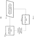
- the network prognostic manger 300 includes an NPM-wireless network operation model 302 (further described below with reference to FIG. 4 ) to predict the behavior of the network, such as network 100 shown in FIG. 1 , based at least in part on the threshold values for signal quality and battery status parameters measured and received from the data controllers.
- NPM-wireless network operation model 302 to predict the behavior of the network, such as network 100 shown in FIG. 1 , based at least in part on the threshold values for signal quality and battery status parameters measured and received from the data controllers.
- the prescription block 306 receives the threshold values from the model 302 and the measured values to perform the graceful degradation of the wireless network.
- FIG. 4 a flow chart 400 for a network-wireless network operation model in accordance with one or more embodiments is shown.
- the method 400 continues to block 406 which provides for acquiring measured value for signal quality, battery status of from the wireless data controller (WDC).
- WDC wireless data controller
- the method 400 determines whether the current operational hours is greater than the sampling duration T. If so, the method 400 continues to block 410 to execute a regression based data processing algorithm (further described below with reference to FIG. 5 ). Otherwise, the method 400 returns to block 406 to acquire additional data until the sampling duration has been met. After executing the steps of block 410 the method 400 proceeds to block 412 and generates threshold values for the signal quality and battery life for the WDC and wireless nodes (WN). The method 400 ends at block 414.
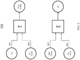
- a diagram 500 for a regression based data processing technique is shown.
- the algorithm is based on a self-learning regression technique.
- the algorithm arrives at averaged operational parameters through machine learning.
- the technique uses a training data set.
- the measure signal quality and battery status received from the data controllers act as the training set for the model shown in FIG. 5 .
- the measured values of the link quality indicator (LQI), battery power and operation hours are provides as inputs.
- the regression technique splits the inputs into two training sets in the format ⁇ [input vector]; output ⁇ as follows: (1) ⁇ [LQI, operational hours]; battery power ⁇ and (2) ⁇ [battery power, operational hours]; LQI ⁇ .
- the neural network is trained suing measured values of LQI, battery power acquired until the operational hours are within the sampling duration described in FIG. 4 .
- the neural network through the choice of weights W1 and W2, learns the relationship between the input and output, wherein in a non-limiting example the weight W1 is different than W2.
- the weights are configurable based on the analysis performed in the regression algorithm.
- the neural network is used to generate threshold values for the LQI and battery power for the measured values for signal quality and battery health parameters.
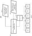
- the threshold values 602 for signal quality and battery status are sent to processing block 604.
- the threshold values are received from NPM-wireless network operation module.
- the measurements of signal quality parameters (LQI, RSSI, PER) battery status and operational hours 606 are sent to processing block 604.
- the measured values of the signal quality and battery health along with operation time are acquired from the network.
- a residual value is calculated and used to enter a state of the state flow 608.
- the residual value is calculated by subtracting the threshold values 602 from the measured values 606. Based on the residual values, a transition from the current state is defined and the state flow 608 enters one of the methods 900-1400.
- the execution of the methods 900-1400 leads to the corresponding actions that are required to implement a graceful degradation process.
- the state flow diagram 700 includes states (S1-S6 that correspond to states 900-1400 of FIG. 6 ) and transitions of the states on the occurrence of events (E0-E6).
- the states are incorporated within the NPM as a set of conditions which define a potential failure mode.
- the conditions are derived from the computed difference between the measurement vector and the threshold vector.
- the event is realized as a signal sent to the current state reflecting the conditions for a particular mode of a potential failure.
- a table 800 is shown to define the states, transitions, and events of FIG. 7 .
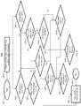
- the method 900 begins at block 901 and continues to block 902 which provides for obtaining wireless data controller (WDC) and wireless node (WN) information.
- WDC wireless data controller
- WN wireless node
- the method 900 flows through to branches analyzing the WDC and the WN.
- the WDC and WN information includes measured data such as battery status, signal strength and operational hours.
- the method 900 provides for comparing the WDC operational hours to the mean-time between failure (MTBF).
- the MBTF is calculated during normal operations of the WDC.
- the method 900 includes determining whether the WN operational hours is less than or equal to MTBF.
- the method 900 proceeds to block 930 where the wireless node is instructed to reduce the data rate. Otherwise, the method 900 proceeds to block 910 where it is determined whether the signal quality parameters are less than or equal to a threshold.
- the signal quality parameters include link quality indicators, RSSI, PER, BER, and channel access failures. If yes, then the method 900 proceeds to block 912 and a determination is made whether a WN battery status is less than or equal to a threshold.
- the threshold is based on an average of measured data collected under normal operating conditions (without any failure conditions) over a configurable period of time.
- the method 900 proceeds to block 916 where it is determined whether the WN battery status is less than or equal to a threshold. If so, the method 900 proceeds to block 914 and continues processing as described above. Otherwise, the method 900, proceeds to block 920 where it is determined whether the WDC battery status is less than or equal to a threshold. If so, the redundant WDC battery status is checked as shown in block 922. If it is determined to be less than or equal to a threshold, the method 900 proceeds to block 930 where the WN is instructed to reduce its data rate. In one or more embodiments, the NPM sends the signal to the WDC to send a signal to all WN to reduce the data rate. The method 900 ends at block 950.
- a method 1000 for requesting WN to switch to a redundant WDC begins at block 1001 and continues to blocks 1002-1012 that include similar steps 902-912 as described in FIG. 9 .
- the method 1000 proceeds to block 1030 to switch the WN to the redundant WDC.
- the method 1000 determines whether the signal parameters are less than or equal to a threshold, if so, the method 1000 continues to block 1012 it is determined whether the WN battery status is less than or equal to a threshold. If so, the method 1000 proceeds to block 1014 where it is determined whether the WDC battery status is less than or equal to a threshold. If so, the method 1000 proceeds to block 1022 where it is determined whether the redundant WDC battery stats is less than or equal to a threshold. If not, at block 1030 as shown, the method 1000 requests the WN to switch to the redundant WDC.
- the method 1000 proceeds to block 1020 where it is determined whether the WDC battery status is less than or equal to the threshold. If so the process continues to block 1022 as described above.
- the method 1000 continues processing towards block 1022 as described above where it is determined whether to send a request the WN to switch to a redundant WDC.
- the method 1000 ends at block 1050.
- a method 1100 for switching a WN to sleep mode begins at block 1101 and continues to blocks 1102-1112 that include similar steps 902-912 as described in FIG. 9 .
- the method 1100 ends at block 1150. Referring back to block 1110, the method 1100 proceeds to block 1116 where it is determined whether the WN battery status is less than or equal to a threshold. Subsequently the method 1100 continues to block 1118 where it is determined whether the WDC battery status is less than or equal to a threshold and continues processing at block 1114 as described above.
- a method 1200 provides for requesting WN to reduce the data rate is provided.
- the method 1200 begins at block 1201 and continues to blocks 1202-1212 that include similar steps 902-912 as described in FIG. 9 .
- block 1212 it is determined whether the WN battery status is less than the threshold and if so, the process continues to blocks 1214 and 1220 where it is determined whether a redundant node/controller exists and check the status of the current WDC battery, respectively. In the event the battery status is below the threshold and no redundant WDC exists, the method 1200 proceeds to block 1216 to reduce the data rate of the WN. The method 1200 ends at block 1250. With reference now to block 1210 it is determined whether the signal parameters are less than or equal to a threshold, the method 1200 proceeds to block 1218 where it is determined whether the WN battery status is less than or equal to a threshold and continues the method 1200 to either block 1220 or 1214.
- a method 1300 for requesting the WN to increase transmission power begins at block 1301 and continues to blocks 1302-1312 that include similar steps 902-912 as described in FIG. 9 .
- the method 1300 determines whether the WN battery status is less than or equal to a threshold. If not, the method proceeds to block 1314 where it is determined whether the WDC battery status is less than or equal to a threshold. If not, the method 1300 proceeds to block 1316 which instructs the WN to increase the transmission power. The method 1300 ends at block 1350.
- a method 1400 for requesting WN to switch a different cluster begins at block 1401 and continues to blocks 1402-1412 that include similar steps 902-912 as described in FIG. 9 .
- the method 1400 determines whether the WN battery status is less than or equal to a threshold. If not, the method proceeds to block 1414 where it is determined whether the WDC battery status is less than or equal to a threshold. If not, the method 1400 proceeds to block 1416 which instructs the WN to increase the transmission power and at block 1418 the WDC performs a recheck of the signal quality parameter. Responsive to the check, the method 1400 proceeds to block 1420 where the WN is instructed to switch to a different cluster if the WN is unable to communicate wireless data controllers in the current cluster including the redundant wireless data controller. The method 1400 ends at block 1450.
- the technical benefits and effects include providing a mechanism to predict a failure mode of the wireless network and ensuring continuous availability of the network.
- the data collected from the system provides the performance pattern of key parameters.
- the graceful degradation of network operations avoids any misinterpretation of performance data leading to incorrect decision during aircraft operation. Therefore, providing seamless replacement of wired network with wireless networks in an aircraft environment.
- the techniques described herein improvement the efficiency of the wireless network and makes wireless aircraft network reliable and robust.
- the collected data helps maintenance personnel to easily and efficiently identify the degraded wireless node or wireless data controller thereby reducing network downtime.
Landscapes
- Engineering & Computer Science (AREA)
- Computer Networks & Wireless Communication (AREA)
- Signal Processing (AREA)
- Physics & Mathematics (AREA)
- General Physics & Mathematics (AREA)
- Quality & Reliability (AREA)
- Automation & Control Theory (AREA)
- Astronomy & Astrophysics (AREA)
- Aviation & Aerospace Engineering (AREA)
- Mobile Radio Communication Systems (AREA)
Abstract
Description
- This application claims the benefit of Indian Application No.
201811019526 filed May 24, 2018 - The present disclosure relates generally to network management, and more specifically to prognosis and graceful degradation of wireless aircraft networks.
- Recent trends in the aviation industry is to move towards a more electric, more intelligent and connected aircrafts. This includes making aircrafts safer and having more availability with minimum downtime. Aircrafts are equipped with monitoring systems to collect different types of data. Data is collected to ensure the safety and reliability of the aircraft systems. The information gathered is used to target improvements to the functioning of the systems and maintenance to reduce the downtime for the aircrafts. These monitoring systems provide the ability to obtain inflight data as well as data generated during ground/taxi operations.
- Also disclosed is a system for prognosis and graceful degradation of a wireless aircraft network including a network manager including a network prognostic manager; one or more wireless data controllers operably coupled to the network manager over a first connection; one or more wireless nodes operably coupled to the one or more data controllers over second, wherein the first connection is a different type of connection than the second connection; wherein the network manager includes a network prognostic manager. The network prognostic manager performs a method including receiving measured parameters from wireless nodes; computing thresholds associated with the parameters; comparing the received parameters to the computed thresholds; identifying a failure condition based on the comparison of the received parameters to the computed thresholds; and based at least in part on the identified failure condition, executing a corrective action.
- In addition to one or more of the features described above, or as an alternative, further embodiments may include parameters that include at least one of a signal quality parameter, battery status, or operational hours for one or more data controllers and one or more wireless nodes.
- In addition to one or more of the features described above, or as an alternative, in further embodiments the signal quality parameter is at least one of a link quality indicator, received signal strength indicator, packet error rate, bit error rate and channel access failure.
- In addition to one or more of the features described above, or as an alternative, further embodiments may include thresholds that are associated with the parameters are based on an average for measurements over a period of time under normal operating conditions.
- In addition to one or more of the features described above, or as an alternative, in further embodiments the one or more wireless data controllers and the one or more wireless nodes are associated with battery status information and operational hours information.
- In addition to one or more of the features described above, or as an alternative, in further embodiments the one or more wireless data controllers and the one or more wireless nodes that communicate over a wireless network are associated with signal quality parameters.
- In addition to one or more of the features described above, or as an alternative, in further embodiments the one or more wireless nodes area associated with multiple wireless data controllers including at least a first wireless data controller and a redundant wireless data controller.
- In addition to one or more of the features described above, or as an alternative, in further embodiments the one or more wireless data controllers and the one or more wireless nodes are configured in clusters for communication.
- In addition to one or more of the features described above, or as an alternative, in further embodiments the one or more wireless nodes are configured to enter a sleep mode based on the identified failure condition.
- In addition to one or more of the features described above, or as an alternative, in further embodiments the one or more wireless nodes are configured to communicate at a specified bandwidth.
- According to one embodiment, a method for implementing a prognosis of a wireless aircraft network including receiving measured parameters from a wireless nodes; computing thresholds associated with the parameters; comparing the received parameters to the computed thresholds; identifying a failure condition based on the comparison of the received parameters to the computed thresholds; and based at least in part on the identified failure condition, executing a corrective action.
- In addition to one or more of the features described above, or as an alternative, further embodiments may include parameters that include at least one of signal quality parameter, battery status, or operational hours for one or more data controllers and one or more wireless nodes.
- In addition to one or more of the features described above, or as an alternative, in further embodiments the signal quality parameter is at least one of a link quality indicator, received signal strength indicator, packet error rate, bit error rate and channel access failure.
- In addition to one or more of the features described above, or as an alternative, further embodiments may include thresholds that are associated with the parameters are based on an average for measurements over a period of time under normal operating conditions.
- In addition to one or more of the features described above, or as an alternative, in further embodiments the identified failure condition includes at least a battery status is below the computed threshold, the corrective action includes reducing a data rate of wireless nodes.
- In addition to one or more of the features described above, or as an alternative, in further embodiments the identified failure condition includes at least the signal quality parameter is below the computed threshold, the corrective action includes increasing a transmission power of a wireless node.
- In addition to one or more of the features described above, or as an alternative, in further embodiments the identified failure condition includes a battery status and signal quality parameter is below the computing threshold for a redundant wireless node, the corrective action includes switching a wireless node to sleep mode.
- In addition to one or more of the features described above, or as an alternative, in further embodiments the identified failure condition includes battery status of wireless data controller is below the computed threshold, the corrective action includes switching a connection to a redundant data controller.
- In addition to one or more of the features described above, or as an alternative, in further embodiments the identified failure condition includes inability to communicating with wireless data controller of a single cluster, the corrective action includes switching wireless node to a different cluster of wireless nodes associated with a different wireless data controller.
- In addition to one or more of the features described above, or as an alternative, in further embodiments the method is performed by a network prognostic manager of a network manager.
- The following descriptions should not be considered limiting in any way. With reference to the accompanying drawings, like elements are numbered alike:
-
FIG. 1 depicts a wireless avionic environment in accordance with one or more embodiments; -
FIG. 2 depicts another wireless avionic environment in accordance with one or more embodiments; -
FIG. 3 depicts a diagram for a network prognostic manger; -
FIG. 4 depicts a flow chart for a wireless network operation model; -
FIG. 5 depicts a regressive model used in the wireless network operation model; -
FIG. 6 depicts a flow chart for graceful degradation technique in accordance with one or more embodiments; -
FIG. 7 depicts a state machine for graceful degradation technique in accordance with one or more embodiments; -
FIG. 8 depicts a table describing the states ofFIG. 7 ; -
FIG. 9 depicts a flow diagram for instructing all wireless nodes to reduce data rates; -
FIG. 10 depicts a flow diagram for instructing wireless nodes to switch to a redundant wireless data controller; -
FIG. 11 depicts a flow diagram for instructing wireless nodes to enter a sleep mode; -
FIG. 12 depicts a flow diagram for instructing wireless nodes to reduce data rates; -
FIG. 13 depicts a flow diagram for instructing wireless nodes to increase transmission power; and -
FIG. 14 depicts a flow diagram for instructing wireless nodes to switch to a different cluster. - In today's environment, various types of sensors are incorporated into existing aircraft networks. The network must be configurable and adaptable. To establish a scalable and adaptive communications between networking entities to developing wireless avionic intra communication infrastructure. Embodiments include ensuring a robust and reliable communication there is a need for continuous monitoring of the network performance. The techniques described herein provide for performing prognostic on the wireless aircraft communication with self-learning and self-recovery.
- One or more embodiments include a prognostic module to detect failure conditions for a potential failure mode and corrective actions for seamless degradation of the network. In addition, a self-learning technique using machine learning (neural network) based regression methods of establishing average operational parameters of the given wireless entities is disclosed. In one or more embodiments, a state flow is established to identify different modes of potential failure from observations of signal quality and battery life of networking entities. In addition, automatic reconfiguration of the network to support operation with reduced capability is implemented. The reconfiguration includes operating at a reduced data rate of the wireless nodes, switching wireless nodes to different wireless data controllers, providing a sleep mode in case of redundant node availability, and increasing a transmit power of the wireless node.
- Now referring to
FIG. 1 , anavionics system 100 having wireless network architecture for implementing the techniques described herein is shown. - The wireless aircraft communications network of
system 100 includes anetwork manager 102,wireless data controller 106 andwireless nodes 108. Thenetwork manager 102 is operably coupled toaircraft applications 104 for monitoring the health and status of an aircraft. Embodiments include a bi-directional communication link between thenetwork manager 102 and the aircraft applications. In one or more embodiments, theaircraft applications 104 include integrated vehicle health management (IVHM), flight control, prognostic health management (PHM), engine health management (EHM) to name a few. Additionally, thenetwork manager 102 is configured to communicate with one or morewireless data controllers 106 over a first connection. Thewireless data controllers 106 are configured to communicate with one or morewireless nodes 108 over a second connection. In one or more embodiments, the first connection is a wired type connections and the second connection is a wireless connection type having a specified bandwidth. Thewireless nodes 108 can be a sensor, an actuator or a similar device and can be cluster and/or associated withrespective data controllers 106. In one or more embodiments, thewireless nodes 108 can be configured inclusters 110 with a respectivewireless data controller 106 based on signal strength, proximity, data rates, and other techniques. - The
wireless data controllers 106 acquire data from thewireless nodes 108 and transmit data to thenetwork manager 102. In turn, thenetwork manger 102 consolidates data received from all the data controllers and transmits the data externally to theaircraft applications 104. In one or more embodiments, thenetwork manager 102 is configured to communicate with theaircraft applications 104 over aircraft interfaces including but not limited to a controller area network (CAN), Ethernet, aeronautical radio incorporated (ARINC), and others. Thedata controllers 106 are configured to communicate with thenetwork manager 102 over a connection such as an Ethernet connection. - Now referring to
FIG. 2 , another diagram of theavionics system 200 in is shown.FIG. 2 includes thenetwork manger 102,data controller 106, andwireless nodes 108 shown inFIG. 1 . In addition,FIG. 2 depicts thewireless channel 204 between thedata controller 106 and thewireless node 108. The data that is exchanged over thewireless channel 204 includes link quality signals, battery status information and operational hours information. Thesystem 200 also includes acommunication channel 206 through which the measured values from thedata controllers 108 and other data is transferred to thenetwork manager 102. Thenetwork manager 102 as shown includes a network prognostic manager (NPM) 202 that uses acquired measured values from the wireless networking entities such as but not limited to signal quality parameters (link quality indicators, received signal strength indicator, bit error rate, channel access failure and packet error rate), batter status of the wireless networking entities and operational hours of the wireless networking entities. In one or more embodiments, the format of a data packet received by the network prognostic manager includes MAC header, payload data, LQI, RSSI, battery information, operational hours, and physical data units (PDU). - The
NPM 202 uses measurements of operational parameters as defined above in order to identify failure conditions for the data controllers and nodes. In the event a failure leading event or network breakdown is detected, theNPM 202 provides network self-recovery through re-configuration of the wireless network and implements graceful degradation. - Referring now to
FIG. 3 , a diagram for a network prognostic manger (NPM) is shown. In one or more embodiments, the NPM uses a mathematical model to predict the normal operation of the network as threshold values of operational parameters such as signal quality and battery status. During operation of the network threshold values are compared against the measured valued for signal quality and battery status as received from the wireless networking entities. The NPM uses stat flow logic to identify the failure conditions, such as those provided inFIG. 7 , in case of any deviations of the network operational parameters from the computed threshold values. The potential failure conditions are identified and used to trigger an execution of a state flow in order to determine one or more network recovery actions corresponding to the failure mode. - In one or more embodiments, the
network prognostic manger 300 includes an NPM-wireless network operation model 302 (further described below with reference toFIG. 4 ) to predict the behavior of the network, such asnetwork 100 shown inFIG. 1 , based at least in part on the threshold values for signal quality and battery status parameters measured and received from the data controllers. - Also, the
prescription block 306 receives the threshold values from themodel 302 and the measured values to perform the graceful degradation of the wireless network. - Now referring to
FIG. 4 , aflow chart 400 for a network-wireless network operation model in accordance with one or more embodiments is shown. - The
method 400 begins atblock 402 where network operation is established and proceeds to block 404, which provides setting a sampling duration for running the NPM wireless network operation model T = N seconds, where N is a positive integer. Themethod 400 continues to block 406 which provides for acquiring measured value for signal quality, battery status of from the wireless data controller (WDC). - At
decision block 408, it is determined whether the current operational hours is greater than the sampling duration T. If so, themethod 400 continues to block 410 to execute a regression based data processing algorithm (further described below with reference toFIG. 5 ). Otherwise, themethod 400 returns to block 406 to acquire additional data until the sampling duration has been met. After executing the steps ofblock 410 themethod 400 proceeds to block 412 and generates threshold values for the signal quality and battery life for the WDC and wireless nodes (WN). Themethod 400 ends atblock 414. - Referring now to
FIG. 5 , a diagram 500 for a regression based data processing technique is shown. In one or more embodiments, the algorithm is based on a self-learning regression technique. The algorithm arrives at averaged operational parameters through machine learning. The technique uses a training data set. The measure signal quality and battery status received from the data controllers act as the training set for the model shown inFIG. 5 . - In one or more embodiments, the measured values of the link quality indicator (LQI), battery power and operation hours are provides as inputs. The regression technique splits the inputs into two training sets in the format {[input vector]; output} as follows: (1) {[LQI, operational hours]; battery power} and (2) {[battery power, operational hours]; LQI}.
- In one or more embodiments, the neural network is trained suing measured values of LQI, battery power acquired until the operational hours are within the sampling duration described in
FIG. 4 . The neural network, through the choice of weights W1 and W2, learns the relationship between the input and output, wherein in a non-limiting example the weight W1 is different than W2. The weights are configurable based on the analysis performed in the regression algorithm. Upon the completion of training, the neural network is used to generate threshold values for the LQI and battery power for the measured values for signal quality and battery health parameters. - Now referring to
FIG. 6 , a data flow diagram 600 for graceful degradation technique is shown. The threshold values 602 for signal quality and battery status are sent toprocessing block 604. The threshold values are received from NPM-wireless network operation module. In addition, the measurements of signal quality parameters (LQI, RSSI, PER) battery status and operational hours 606 (measured values) are sent toprocessing block 604. In one or more embodiments, the measured values of the signal quality and battery health along with operation time are acquired from the network. Atprocessing block 604, a residual value is calculated and used to enter a state of thestate flow 608. The residual value, as shown atblock 604, is calculated by subtracting the threshold values 602 from the measured values 606. Based on the residual values, a transition from the current state is defined and thestate flow 608 enters one of the methods 900-1400. The execution of the methods 900-1400 leads to the corresponding actions that are required to implement a graceful degradation process. - Now referring to
FIG. 7 , a state flow diagram 700 for implementing a graceful degradation of a network is shown. The state flow diagram 700 includes states (S1-S6 that correspond to states 900-1400 ofFIG. 6 ) and transitions of the states on the occurrence of events (E0-E6). The states are incorporated within the NPM as a set of conditions which define a potential failure mode. The conditions are derived from the computed difference between the measurement vector and the threshold vector. The event is realized as a signal sent to the current state reflecting the conditions for a particular mode of a potential failure. With reference now toFIG. 8 , a table 800 is shown to define the states, transitions, and events ofFIG. 7 . - Now referring to
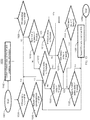
FIG. 9 , amethod 900 for reducing the data rate for wireless nodes is shown. Themethod 900 begins atblock 901 and continues to block 902 which provides for obtaining wireless data controller (WDC) and wireless node (WN) information. - After obtaining WDC and WN information, the
method 900 flows through to branches analyzing the WDC and the WN. In one or more embodiments, the WDC and WN information includes measured data such as battery status, signal strength and operational hours. Atblock 904, themethod 900 provides for comparing the WDC operational hours to the mean-time between failure (MTBF). In one or more embodiments, the MBTF is calculated during normal operations of the WDC. Atblock 908, themethod 900 includes determining whether the WN operational hours is less than or equal to MTBF. - At
block 906 it is determined if the redundant WDC operational hours are less than or equal to the MTBF. If it is determined that the redundant WDC's operational hours are less than or equal to the MTBF, themethod 900 proceeds to block 930 where the wireless node is instructed to reduce the data rate. Otherwise, themethod 900 proceeds to block 910 where it is determined whether the signal quality parameters are less than or equal to a threshold. In one or more embodiments, the signal quality parameters include link quality indicators, RSSI, PER, BER, and channel access failures. If yes, then themethod 900 proceeds to block 912 and a determination is made whether a WN battery status is less than or equal to a threshold. In one or more embodiments, the threshold is based on an average of measured data collected under normal operating conditions (without any failure conditions) over a configurable period of time. - If yes, at
block 914 it is determined whether the WDC battery status is less than or equal to a threshold. If so, themethod 900 proceeds to block where it is determined whether the redundant WDC battery status is less than or equal to a threshold and continues processing. - Referring back to block 910, if the signal quality is determined to be greater than the threshold, the
method 900 proceeds to block 916 where it is determined whether the WN battery status is less than or equal to a threshold. If so, themethod 900 proceeds to block 914 and continues processing as described above. Otherwise, themethod 900, proceeds to block 920 where it is determined whether the WDC battery status is less than or equal to a threshold. If so, the redundant WDC battery status is checked as shown inblock 922. If it is determined to be less than or equal to a threshold, themethod 900 proceeds to block 930 where the WN is instructed to reduce its data rate. In one or more embodiments, the NPM sends the signal to the WDC to send a signal to all WN to reduce the data rate. Themethod 900 ends atblock 950. - Now referring to
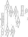
FIG. 10 , amethod 1000 for requesting WN to switch to a redundant WDC is provided. Themethod 1000 begins atblock 1001 and continues to blocks 1002-1012 that include similar steps 902-912 as described inFIG. 9 . - With reference to block 1006, if it is determined that the redundant WDC operations hours are less than or equal to MTBF, the
method 1000 proceeds to block 1030 to switch the WN to the redundant WDC. - With reference to block 1010 it is determined whether the signal parameters are less than or equal to a threshold, if so, the
method 1000 continues to block 1012 it is determined whether the WN battery status is less than or equal to a threshold. If so, themethod 1000 proceeds to block 1014 where it is determined whether the WDC battery status is less than or equal to a threshold. If so, themethod 1000 proceeds to block 1022 where it is determined whether the redundant WDC battery stats is less than or equal to a threshold. If not, atblock 1030 as shown, themethod 1000 requests the WN to switch to the redundant WDC. - Referring back to
block 1016, if the WN battery status is not less than or equal to the threshold, themethod 1000 proceeds to block 1020 where it is determined whether the WDC battery status is less than or equal to the threshold. If so the process continues to block 1022 as described above. - At
block 1018, it is determined whether the WDC battery status is less than or equal to a threshold and themethod 1000 continues processing towardsblock 1022 as described above where it is determined whether to send a request the WN to switch to a redundant WDC. Themethod 1000 ends atblock 1050. - Now referring to
FIG. 11 , amethod 1100 for switching a WN to sleep mode is provided. Themethod 1100 begins atblock 1101 and continues to blocks 1102-1112 that include similar steps 902-912 as described inFIG. 9 . - With reference to block 1114, it is determined whether the node is redundant WN and in the event it is, the WN node is instructed to switch to sleep mode at
block 1120. Themethod 1100 ends atblock 1150. Referring back toblock 1110, themethod 1100 proceeds to block 1116 where it is determined whether the WN battery status is less than or equal to a threshold. Subsequently themethod 1100 continues to block 1118 where it is determined whether the WDC battery status is less than or equal to a threshold and continues processing atblock 1114 as described above. - Now referring to
FIG. 12 , amethod 1200 provides for requesting WN to reduce the data rate is provided. Themethod 1200 begins atblock 1201 and continues to blocks 1202-1212 that include similar steps 902-912 as described inFIG. 9 . - With reference now to block 1212 it is determined whether the WN battery status is less than the threshold and if so, the process continues to
blocks method 1200 proceeds to block 1216 to reduce the data rate of the WN. Themethod 1200 ends atblock 1250. With reference now to block 1210 it is determined whether the signal parameters are less than or equal to a threshold, themethod 1200 proceeds to block 1218 where it is determined whether the WN battery status is less than or equal to a threshold and continues themethod 1200 to either block 1220 or 1214. - Now referring to
FIG. 13 , amethod 1300 for requesting the WN to increase transmission power is provided. Themethod 1300 begins atblock 1301 and continues to blocks 1302-1312 that include similar steps 902-912 as described inFIG. 9 . - With reference to block 1312, the
method 1300 determines whether the WN battery status is less than or equal to a threshold. If not, the method proceeds to block 1314 where it is determined whether the WDC battery status is less than or equal to a threshold. If not, themethod 1300 proceeds to block 1316 which instructs the WN to increase the transmission power. Themethod 1300 ends atblock 1350. - Now referring to
FIG. 14 , amethod 1400 for requesting WN to switch a different cluster is provided. Themethod 1400 begins atblock 1401 and continues to blocks 1402-1412 that include similar steps 902-912 as described inFIG. 9 . - With reference to block 1412, the
method 1400 determines whether the WN battery status is less than or equal to a threshold. If not, the method proceeds to block 1414 where it is determined whether the WDC battery status is less than or equal to a threshold. If not, themethod 1400 proceeds to block 1416 which instructs the WN to increase the transmission power and atblock 1418 the WDC performs a recheck of the signal quality parameter. Responsive to the check, themethod 1400 proceeds to block 1420 where the WN is instructed to switch to a different cluster if the WN is unable to communicate wireless data controllers in the current cluster including the redundant wireless data controller. Themethod 1400 ends atblock 1450. - The technical benefits and effects include providing a mechanism to predict a failure mode of the wireless network and ensuring continuous availability of the network. The data collected from the system provides the performance pattern of key parameters. The graceful degradation of network operations avoids any misinterpretation of performance data leading to incorrect decision during aircraft operation. Therefore, providing seamless replacement of wired network with wireless networks in an aircraft environment.
- The techniques described herein improvement the efficiency of the wireless network and makes wireless aircraft network reliable and robust. The collected data helps maintenance personnel to easily and efficiently identify the degraded wireless node or wireless data controller thereby reducing network downtime.
- A detailed description of one or more embodiments of the disclosed apparatus and method are presented herein by way of exemplification and not limitation with reference to the Figures.
- The term "about" is intended to include the degree of error associated with measurement of the particular quantity based upon the equipment available at the time of filing the application.
- The terminology used herein is for the purpose of describing particular embodiments only and is not intended to be limiting of the present disclosure. As used herein, the singular forms "a", "an" and "the" are intended to include the plural forms as well, unless the context clearly indicates otherwise. It will be further understood that the terms "comprises" and/or "comprising," when used in this specification, specify the presence of stated features, integers, steps, operations, elements, and/or components, but do not preclude the presence or addition of one or more other features, integers, steps, operations, element components, and/or groups thereof.
- While the present disclosure has been described with reference to an exemplary embodiment or embodiments, it will be understood by those skilled in the art that various changes may be made and equivalents may be substituted for elements thereof without departing from the scope of the present disclosure. In addition, many modifications may be made to adapt a particular situation or material to the teachings of the present disclosure without departing from the essential scope thereof. Therefore, it is intended that the present disclosure not be limited to the particular embodiment disclosed as the best mode contemplated for carrying out this present disclosure, but that the present disclosure will include all embodiments falling within the scope of the claims.
Claims (15)
- A system for prognosis of a wireless aircraft network comprising:a network manager including a network prognostic manager;one or more wireless data controllers operably coupled to the network manager over a first connection;one or more wireless nodes operably coupled to the one or more data controllers over a second connection, wherein the second connection is a different type of connection than the first connection;wherein the network manager includes a network prognostic manager configured to:receive measured parameters from the nodes;compute thresholds associated with the parameters;compare the received parameters to the computed thresholds;identify a failure condition based on the comparison of the received parameters to the computed thresholds; andexecute a corrective action based at least in part on the identified failure condition.
- The system of claim 1, wherein the parameters include at least one of signal quality parameter, battery status, or operational hours for one or more data controllers and one or more wireless nodes, wherein the signal quality parameter is at least one of link quality indicator, received signal strength indicator, packet error rate, bit error rate and channel access failure.
- The system of claim 1 or 2, wherein the thresholds associated with the parameters are based on an average for measurements over a period of time under normal operating conditions.
- The system of claim 2, wherein the one or more wireless data controllers and the one or more wireless nodes are associated with battery status information and operational hours information.
- The system of claim 2, wherein the one or more wireless data controllers and the one or more wireless nodes that communicate over a wireless network are associated with signal quality parameters.
- The system of any preceding claim, wherein the one or more wireless nodes are associated with multiple wireless data controllers including at least a first wireless data controller and a redundant wireless data controller.
- The system of any preceding claim, wherein the one or more wireless data controllers and the one or more wireless nodes are configured in clusters for communication, and wherein the one or more wireless nodes are configured to enter a sleep mode based on the identified failure condition.
- A method implementing a prognostic of a wireless aircraft network comprising;
receiving measured parameters from nodes over a wireless communications network;
computing thresholds associated with the parameters;
comparing the received parameters to the computed thresholds;
identifying a failure condition based on the comparison of the received parameters to the computed thresholds; and
based at least in part on the identified failure condition, executing a corrective action. - The method of claim 8, wherein the parameters include at least one of signal quality parameter, battery status, or operational hours for one or more data controllers and one or more wireless nodes, wherein the signal quality parameter is at least one of link quality indicator, received signal strength indicator, packet error rate, bit error rate and channel access failure.
- The method of claim 8 or 9, wherein the thresholds associated with the parameters are based on an average for measurements over a period of time under normal operating conditions.
- The method of claim 9, wherein the identified failure condition includes at least a battery status is below the computed threshold, the corrective action includes reducing a data rate of wireless nodes.
- The method of claim 9, wherein the identified failure condition includes at least the signal quality parameter is below the computed threshold, the corrective action includes increasing a transmission power of a wireless node.
- The method of claim 9, wherein the identified failure condition includes a battery status and signal quality parameter is below the computing threshold for a redundant wireless node, the corrective action includes switching a wireless node to sleep mode.
- The method of claim 9, wherein the identified failure condition includes battery status of wireless data controller is below the computed threshold, the corrective action includes switching a connection to a redundant data controller.
- The method of any preceding claim, wherein the identified failure condition includes inability to communicating with wireless data controller of a single cluster, the corrective action includes switching wireless node to a different cluster of wireless nodes associated with a different wireless data controller.
Applications Claiming Priority (1)
| Application Number | Priority Date | Filing Date | Title |
|---|---|---|---|
| IN201811019526 | 2018-05-24 |
Publications (2)
| Publication Number | Publication Date |
|---|---|
| EP3572895A1 true EP3572895A1 (en) | 2019-11-27 |
| EP3572895B1 EP3572895B1 (en) | 2022-04-06 |
Family
ID=66826804
Family Applications (1)
| Application Number | Title | Priority Date | Filing Date |
|---|---|---|---|
| EP19175973.7A Active EP3572895B1 (en) | 2018-05-24 | 2019-05-22 | Prognosis and graceful degradation of wireless aircraft networks |
Country Status (4)
| Country | Link |
|---|---|
| US (1) | US10944623B2 (en) |
| EP (1) | EP3572895B1 (en) |
| BR (1) | BR102019010233A2 (en) |
| CA (1) | CA3044233A1 (en) |
Families Citing this family (3)
| Publication number | Priority date | Publication date | Assignee | Title |
|---|---|---|---|---|
| US11974171B2 (en) * | 2020-02-14 | 2024-04-30 | Panasonic Avionics Corporation | Antenna blockage detection and mitigation |
| EP4012515B1 (en) * | 2020-12-09 | 2025-03-19 | ABB Schweiz AG | Preventive controller switchover |
| CN115828062A (en) * | 2022-11-24 | 2023-03-21 | 国网山东省电力公司淄博供电公司 | An identification method and identification device for broadband multi-state signals in an active distribution network |
Citations (4)
| Publication number | Priority date | Publication date | Assignee | Title |
|---|---|---|---|---|
| WO2005096571A1 (en) * | 2004-03-24 | 2005-10-13 | Honeywell International Inc. | Aircraft engine sensor network using wireless sensor communication modules |
| EP1791047A2 (en) * | 2005-11-23 | 2007-05-30 | Lockheed Martin Corporation | System to monitor the health of a structure, sensor nodes, program product, and related methods |
| EP2642259A1 (en) * | 2012-03-22 | 2013-09-25 | Airbus Operations Limited | Sensor device and method for communicating with sensor devices |
| US20150330869A1 (en) * | 2012-06-06 | 2015-11-19 | Harris Corporation | Wireless engine monitoring system and associated engine wireless sensor network |
Family Cites Families (11)
| Publication number | Priority date | Publication date | Assignee | Title |
|---|---|---|---|---|
| US20030087636A1 (en) * | 2001-11-07 | 2003-05-08 | General Motors Corporation. | Method for providing multi-path communication for a mobile vehicle |
| US7286835B1 (en) | 2004-09-10 | 2007-10-23 | Airespace, Inc. | Enhanced wireless node location using differential signal strength metric |
| US7822417B1 (en) | 2005-12-01 | 2010-10-26 | At&T Intellectual Property Ii, L.P. | Method for predictive maintenance of a communication network |
| KR101682034B1 (en) * | 2008-08-18 | 2016-12-05 | 삼성전자주식회사 | Apparatus and method for using secondary frequency assignment optionnally in a wireless communication system using multiple band |
| US8199722B2 (en) * | 2009-01-08 | 2012-06-12 | Honeywell International Inc. | Method and system for datalink ground station selection |
| US8831524B2 (en) | 2011-04-11 | 2014-09-09 | University Of Maryland, College Park | Systems, methods, devices, and computer program products for control and performance prediction in wireless networks |
| US9030979B2 (en) * | 2011-05-11 | 2015-05-12 | Qualcomm Incorporated | Reducing power consumption in multi-threaded processor mobile devices |
| SG10201407299RA (en) | 2013-11-08 | 2015-06-29 | Accenture Global Services Ltd | Network node failure predictive system |
| JP2016127436A (en) * | 2015-01-05 | 2016-07-11 | 富士通株式会社 | Radio equipment and transmission power control method |
| US20170034720A1 (en) | 2015-07-28 | 2017-02-02 | Futurewei Technologies, Inc. | Predicting Network Performance |
| US10313982B1 (en) * | 2017-04-27 | 2019-06-04 | Thales Avionics, Inc. | Cooperative realtime management of noise interference in ISM band |
-
2018
- 2018-07-25 US US16/044,553 patent/US10944623B2/en active Active
-
2019
- 2019-05-20 BR BR102019010233-0A patent/BR102019010233A2/en unknown
- 2019-05-22 EP EP19175973.7A patent/EP3572895B1/en active Active
- 2019-05-23 CA CA3044233A patent/CA3044233A1/en active Pending
Patent Citations (4)
| Publication number | Priority date | Publication date | Assignee | Title |
|---|---|---|---|---|
| WO2005096571A1 (en) * | 2004-03-24 | 2005-10-13 | Honeywell International Inc. | Aircraft engine sensor network using wireless sensor communication modules |
| EP1791047A2 (en) * | 2005-11-23 | 2007-05-30 | Lockheed Martin Corporation | System to monitor the health of a structure, sensor nodes, program product, and related methods |
| EP2642259A1 (en) * | 2012-03-22 | 2013-09-25 | Airbus Operations Limited | Sensor device and method for communicating with sensor devices |
| US20150330869A1 (en) * | 2012-06-06 | 2015-11-19 | Harris Corporation | Wireless engine monitoring system and associated engine wireless sensor network |
Also Published As
| Publication number | Publication date |
|---|---|
| US20190363930A1 (en) | 2019-11-28 |
| EP3572895B1 (en) | 2022-04-06 |
| CA3044233A1 (en) | 2019-11-24 |
| US10944623B2 (en) | 2021-03-09 |
| BR102019010233A2 (en) | 2019-11-26 |
Similar Documents
| Publication | Publication Date | Title |
|---|---|---|
| EP3572895B1 (en) | Prognosis and graceful degradation of wireless aircraft networks | |
| EP2775457B1 (en) | Electrical power health monitoring system | |
| US20090292951A1 (en) | Method and device for fault location in a system | |
| CN119011374B (en) | A master-slave switching method and system based on device synchronization | |
| WO2017086739A1 (en) | Method and device for sharing state related information | |
| CN118400299B (en) | Vehicle-mounted network intelligent monitoring system based on cloud computing | |
| CN107276710B (en) | Time-triggered Ethernet fault diagnosis method based on time synchronization state monitoring | |
| US20210407281A1 (en) | Monitor circuit for summarizing sensor data | |
| CN117014471A (en) | Engineering thing networking safety monitoring system based on artificial intelligence | |
| CN120567759A (en) | Autonomous fault-tolerant system and method for dual-mode hot switching | |
| US20190210622A1 (en) | System, prediction unit, and method for predicting a failure of at least one unit for monitoring and/or controlling transportation traffic | |
| CN120547116A (en) | Electric power communication optical transmission service path optimization method based on reinforcement learning | |
| CN113784377A (en) | Data communication method, device, electronic equipment and storage medium | |
| US20210345451A1 (en) | Environment aware node redundancy and optimized roaming | |
| US11159388B2 (en) | Method for detecting and determining a failure probability of a radio network and central computer | |
| CN110691022A (en) | Communication load adjusting method, device and system based on CAN bus | |
| CN108418724A (en) | Next-generation key message infrastructure network intelligent management system based on cloud computing | |
| CN107018016B (en) | A method and apparatus for monitoring networked devices | |
| WO2018125488A1 (en) | Technologies for predictive monitoring of a characteristic of a system | |
| JP2022182636A (en) | Remote monitoring control system, server device, and communication failure prediction method | |
| CN119376512B (en) | Server power supply control system | |
| CN119814498B (en) | A design method for network system architecture of intelligent connected buses based on link redundancy | |
| CN111634764A (en) | Internet of things terminal abnormity mutual diagnosis method under scene of multiple elevators in same machine room | |
| JP7741014B2 (en) | Distributed system and distributed device constituting the distributed system | |
| CN108880836A (en) | A kind of network topology integrality diagnostic method and system based on Ethernet |
Legal Events
| Date | Code | Title | Description |
|---|---|---|---|
| PUAI | Public reference made under article 153(3) epc to a published international application that has entered the european phase |
Free format text: ORIGINAL CODE: 0009012 |
|
| STAA | Information on the status of an ep patent application or granted ep patent |
Free format text: STATUS: THE APPLICATION HAS BEEN PUBLISHED |
|
| AK | Designated contracting states |
Kind code of ref document: A1 Designated state(s): AL AT BE BG CH CY CZ DE DK EE ES FI FR GB GR HR HU IE IS IT LI LT LU LV MC MK MT NL NO PL PT RO RS SE SI SK SM TR |
|
| AX | Request for extension of the european patent |
Extension state: BA ME |
|
| STAA | Information on the status of an ep patent application or granted ep patent |
Free format text: STATUS: REQUEST FOR EXAMINATION WAS MADE |
|
| 17P | Request for examination filed |
Effective date: 20191203 |
|
| RBV | Designated contracting states (corrected) |
Designated state(s): AL AT BE BG CH CY CZ DE DK EE ES FI FR GB GR HR HU IE IS IT LI LT LU LV MC MK MT NL NO PL PT RO RS SE SI SK SM TR |
|
| STAA | Information on the status of an ep patent application or granted ep patent |
Free format text: STATUS: EXAMINATION IS IN PROGRESS |
|
| 17Q | First examination report despatched |
Effective date: 20201125 |
|
| GRAP | Despatch of communication of intention to grant a patent |
Free format text: ORIGINAL CODE: EPIDOSNIGR1 |
|
| STAA | Information on the status of an ep patent application or granted ep patent |
Free format text: STATUS: GRANT OF PATENT IS INTENDED |
|
| INTG | Intention to grant announced |
Effective date: 20211019 |
|
| GRAS | Grant fee paid |
Free format text: ORIGINAL CODE: EPIDOSNIGR3 |
|
| GRAA | (expected) grant |
Free format text: ORIGINAL CODE: 0009210 |
|
| STAA | Information on the status of an ep patent application or granted ep patent |
Free format text: STATUS: THE PATENT HAS BEEN GRANTED |
|
| AK | Designated contracting states |
Kind code of ref document: B1 Designated state(s): AL AT BE BG CH CY CZ DE DK EE ES FI FR GB GR HR HU IE IS IT LI LT LU LV MC MK MT NL NO PL PT RO RS SE SI SK SM TR |
|
| REG | Reference to a national code |
Ref country code: GB Ref legal event code: FG4D |
|
| REG | Reference to a national code |
Ref country code: CH Ref legal event code: EP |
|
| REG | Reference to a national code |
Ref country code: AT Ref legal event code: REF Ref document number: 1481947 Country of ref document: AT Kind code of ref document: T Effective date: 20220415 |
|
| REG | Reference to a national code |
Ref country code: DE Ref legal event code: R096 Ref document number: 602019013274 Country of ref document: DE |
|
| REG | Reference to a national code |
Ref country code: IE Ref legal event code: FG4D |
|
| REG | Reference to a national code |
Ref country code: LT Ref legal event code: MG9D |
|
| REG | Reference to a national code |
Ref country code: NL Ref legal event code: MP Effective date: 20220406 |
|
| REG | Reference to a national code |
Ref country code: AT Ref legal event code: MK05 Ref document number: 1481947 Country of ref document: AT Kind code of ref document: T Effective date: 20220406 |
|
| PG25 | Lapsed in a contracting state [announced via postgrant information from national office to epo] |
Ref country code: NL Free format text: LAPSE BECAUSE OF FAILURE TO SUBMIT A TRANSLATION OF THE DESCRIPTION OR TO PAY THE FEE WITHIN THE PRESCRIBED TIME-LIMIT Effective date: 20220406 |
|
| PG25 | Lapsed in a contracting state [announced via postgrant information from national office to epo] |
Ref country code: SE Free format text: LAPSE BECAUSE OF FAILURE TO SUBMIT A TRANSLATION OF THE DESCRIPTION OR TO PAY THE FEE WITHIN THE PRESCRIBED TIME-LIMIT Effective date: 20220406 Ref country code: PT Free format text: LAPSE BECAUSE OF FAILURE TO SUBMIT A TRANSLATION OF THE DESCRIPTION OR TO PAY THE FEE WITHIN THE PRESCRIBED TIME-LIMIT Effective date: 20220808 Ref country code: NO Free format text: LAPSE BECAUSE OF FAILURE TO SUBMIT A TRANSLATION OF THE DESCRIPTION OR TO PAY THE FEE WITHIN THE PRESCRIBED TIME-LIMIT Effective date: 20220706 Ref country code: LT Free format text: LAPSE BECAUSE OF FAILURE TO SUBMIT A TRANSLATION OF THE DESCRIPTION OR TO PAY THE FEE WITHIN THE PRESCRIBED TIME-LIMIT Effective date: 20220406 Ref country code: HR Free format text: LAPSE BECAUSE OF FAILURE TO SUBMIT A TRANSLATION OF THE DESCRIPTION OR TO PAY THE FEE WITHIN THE PRESCRIBED TIME-LIMIT Effective date: 20220406 Ref country code: GR Free format text: LAPSE BECAUSE OF FAILURE TO SUBMIT A TRANSLATION OF THE DESCRIPTION OR TO PAY THE FEE WITHIN THE PRESCRIBED TIME-LIMIT Effective date: 20220707 Ref country code: FI Free format text: LAPSE BECAUSE OF FAILURE TO SUBMIT A TRANSLATION OF THE DESCRIPTION OR TO PAY THE FEE WITHIN THE PRESCRIBED TIME-LIMIT Effective date: 20220406 Ref country code: ES Free format text: LAPSE BECAUSE OF FAILURE TO SUBMIT A TRANSLATION OF THE DESCRIPTION OR TO PAY THE FEE WITHIN THE PRESCRIBED TIME-LIMIT Effective date: 20220406 Ref country code: BG Free format text: LAPSE BECAUSE OF FAILURE TO SUBMIT A TRANSLATION OF THE DESCRIPTION OR TO PAY THE FEE WITHIN THE PRESCRIBED TIME-LIMIT Effective date: 20220706 Ref country code: AT Free format text: LAPSE BECAUSE OF FAILURE TO SUBMIT A TRANSLATION OF THE DESCRIPTION OR TO PAY THE FEE WITHIN THE PRESCRIBED TIME-LIMIT Effective date: 20220406 |
|
| PG25 | Lapsed in a contracting state [announced via postgrant information from national office to epo] |
Ref country code: RS Free format text: LAPSE BECAUSE OF FAILURE TO SUBMIT A TRANSLATION OF THE DESCRIPTION OR TO PAY THE FEE WITHIN THE PRESCRIBED TIME-LIMIT Effective date: 20220406 Ref country code: PL Free format text: LAPSE BECAUSE OF FAILURE TO SUBMIT A TRANSLATION OF THE DESCRIPTION OR TO PAY THE FEE WITHIN THE PRESCRIBED TIME-LIMIT Effective date: 20220406 Ref country code: LV Free format text: LAPSE BECAUSE OF FAILURE TO SUBMIT A TRANSLATION OF THE DESCRIPTION OR TO PAY THE FEE WITHIN THE PRESCRIBED TIME-LIMIT Effective date: 20220406 Ref country code: IS Free format text: LAPSE BECAUSE OF FAILURE TO SUBMIT A TRANSLATION OF THE DESCRIPTION OR TO PAY THE FEE WITHIN THE PRESCRIBED TIME-LIMIT Effective date: 20220806 |
|
| REG | Reference to a national code |
Ref country code: CH Ref legal event code: PL |
|
| REG | Reference to a national code |
Ref country code: DE Ref legal event code: R097 Ref document number: 602019013274 Country of ref document: DE |
|
| REG | Reference to a national code |
Ref country code: BE Ref legal event code: MM Effective date: 20220531 |
|
| PG25 | Lapsed in a contracting state [announced via postgrant information from national office to epo] |
Ref country code: SM Free format text: LAPSE BECAUSE OF FAILURE TO SUBMIT A TRANSLATION OF THE DESCRIPTION OR TO PAY THE FEE WITHIN THE PRESCRIBED TIME-LIMIT Effective date: 20220406 Ref country code: SK Free format text: LAPSE BECAUSE OF FAILURE TO SUBMIT A TRANSLATION OF THE DESCRIPTION OR TO PAY THE FEE WITHIN THE PRESCRIBED TIME-LIMIT Effective date: 20220406 Ref country code: RO Free format text: LAPSE BECAUSE OF FAILURE TO SUBMIT A TRANSLATION OF THE DESCRIPTION OR TO PAY THE FEE WITHIN THE PRESCRIBED TIME-LIMIT Effective date: 20220406 Ref country code: MC Free format text: LAPSE BECAUSE OF FAILURE TO SUBMIT A TRANSLATION OF THE DESCRIPTION OR TO PAY THE FEE WITHIN THE PRESCRIBED TIME-LIMIT Effective date: 20220406 Ref country code: LU Free format text: LAPSE BECAUSE OF NON-PAYMENT OF DUE FEES Effective date: 20220522 Ref country code: LI Free format text: LAPSE BECAUSE OF NON-PAYMENT OF DUE FEES Effective date: 20220531 Ref country code: EE Free format text: LAPSE BECAUSE OF FAILURE TO SUBMIT A TRANSLATION OF THE DESCRIPTION OR TO PAY THE FEE WITHIN THE PRESCRIBED TIME-LIMIT Effective date: 20220406 Ref country code: DK Free format text: LAPSE BECAUSE OF FAILURE TO SUBMIT A TRANSLATION OF THE DESCRIPTION OR TO PAY THE FEE WITHIN THE PRESCRIBED TIME-LIMIT Effective date: 20220406 Ref country code: CZ Free format text: LAPSE BECAUSE OF FAILURE TO SUBMIT A TRANSLATION OF THE DESCRIPTION OR TO PAY THE FEE WITHIN THE PRESCRIBED TIME-LIMIT Effective date: 20220406 Ref country code: CH Free format text: LAPSE BECAUSE OF NON-PAYMENT OF DUE FEES Effective date: 20220531 |
|
| PLBE | No opposition filed within time limit |
Free format text: ORIGINAL CODE: 0009261 |
|
| STAA | Information on the status of an ep patent application or granted ep patent |
Free format text: STATUS: NO OPPOSITION FILED WITHIN TIME LIMIT |
|
| 26N | No opposition filed |
Effective date: 20230110 |
|
| PG25 | Lapsed in a contracting state [announced via postgrant information from national office to epo] |
Ref country code: AL Free format text: LAPSE BECAUSE OF FAILURE TO SUBMIT A TRANSLATION OF THE DESCRIPTION OR TO PAY THE FEE WITHIN THE PRESCRIBED TIME-LIMIT Effective date: 20220406 |
|
| PG25 | Lapsed in a contracting state [announced via postgrant information from national office to epo] |
Ref country code: IE Free format text: LAPSE BECAUSE OF NON-PAYMENT OF DUE FEES Effective date: 20220522 |
|
| PG25 | Lapsed in a contracting state [announced via postgrant information from national office to epo] |
Ref country code: SI Free format text: LAPSE BECAUSE OF FAILURE TO SUBMIT A TRANSLATION OF THE DESCRIPTION OR TO PAY THE FEE WITHIN THE PRESCRIBED TIME-LIMIT Effective date: 20220406 Ref country code: BE Free format text: LAPSE BECAUSE OF NON-PAYMENT OF DUE FEES Effective date: 20220531 |
|
| PG25 | Lapsed in a contracting state [announced via postgrant information from national office to epo] |
Ref country code: IT Free format text: LAPSE BECAUSE OF FAILURE TO SUBMIT A TRANSLATION OF THE DESCRIPTION OR TO PAY THE FEE WITHIN THE PRESCRIBED TIME-LIMIT Effective date: 20220406 |
|
| PG25 | Lapsed in a contracting state [announced via postgrant information from national office to epo] |
Ref country code: HU Free format text: LAPSE BECAUSE OF FAILURE TO SUBMIT A TRANSLATION OF THE DESCRIPTION OR TO PAY THE FEE WITHIN THE PRESCRIBED TIME-LIMIT; INVALID AB INITIO Effective date: 20190522 |
|
| PG25 | Lapsed in a contracting state [announced via postgrant information from national office to epo] |
Ref country code: MK Free format text: LAPSE BECAUSE OF FAILURE TO SUBMIT A TRANSLATION OF THE DESCRIPTION OR TO PAY THE FEE WITHIN THE PRESCRIBED TIME-LIMIT Effective date: 20220406 Ref country code: CY Free format text: LAPSE BECAUSE OF FAILURE TO SUBMIT A TRANSLATION OF THE DESCRIPTION OR TO PAY THE FEE WITHIN THE PRESCRIBED TIME-LIMIT Effective date: 20220406 |
|
| PG25 | Lapsed in a contracting state [announced via postgrant information from national office to epo] |
Ref country code: MT Free format text: LAPSE BECAUSE OF FAILURE TO SUBMIT A TRANSLATION OF THE DESCRIPTION OR TO PAY THE FEE WITHIN THE PRESCRIBED TIME-LIMIT Effective date: 20220406 |
|
| PG25 | Lapsed in a contracting state [announced via postgrant information from national office to epo] |
Ref country code: BG Free format text: LAPSE BECAUSE OF FAILURE TO SUBMIT A TRANSLATION OF THE DESCRIPTION OR TO PAY THE FEE WITHIN THE PRESCRIBED TIME-LIMIT Effective date: 20220406 |
|
| PG25 | Lapsed in a contracting state [announced via postgrant information from national office to epo] |
Ref country code: BG Free format text: LAPSE BECAUSE OF FAILURE TO SUBMIT A TRANSLATION OF THE DESCRIPTION OR TO PAY THE FEE WITHIN THE PRESCRIBED TIME-LIMIT Effective date: 20220406 |
|
| PGFP | Annual fee paid to national office [announced via postgrant information from national office to epo] |
Ref country code: DE Payment date: 20250423 Year of fee payment: 7 |
|
| PGFP | Annual fee paid to national office [announced via postgrant information from national office to epo] |
Ref country code: GB Payment date: 20250423 Year of fee payment: 7 |
|
| PGFP | Annual fee paid to national office [announced via postgrant information from national office to epo] |
Ref country code: FR Payment date: 20250423 Year of fee payment: 7 |
|
| PG25 | Lapsed in a contracting state [announced via postgrant information from national office to epo] |
Ref country code: TR Free format text: LAPSE BECAUSE OF FAILURE TO SUBMIT A TRANSLATION OF THE DESCRIPTION OR TO PAY THE FEE WITHIN THE PRESCRIBED TIME-LIMIT Effective date: 20220406 |
|
| P01 | Opt-out of the competence of the unified patent court (upc) registered |
Free format text: CASE NUMBER: UPC_APP_0017994_3572895/2025 Effective date: 20251217 |