EP3572830A1 - Phase correction for object detection including tdma - Google Patents
Phase correction for object detection including tdma Download PDFInfo
- Publication number
- EP3572830A1 EP3572830A1 EP19175387.0A EP19175387A EP3572830A1 EP 3572830 A1 EP3572830 A1 EP 3572830A1 EP 19175387 A EP19175387 A EP 19175387A EP 3572830 A1 EP3572830 A1 EP 3572830A1
- Authority
- EP
- European Patent Office
- Prior art keywords
- signals
- received
- trace
- covariance matrix
- relationship
- Prior art date
- Legal status (The legal status is an assumption and is not a legal conclusion. Google has not performed a legal analysis and makes no representation as to the accuracy of the status listed.)
- Pending
Links
Images


Classifications
-
- G—PHYSICS
- G01—MEASURING; TESTING
- G01S—RADIO DIRECTION-FINDING; RADIO NAVIGATION; DETERMINING DISTANCE OR VELOCITY BY USE OF RADIO WAVES; LOCATING OR PRESENCE-DETECTING BY USE OF THE REFLECTION OR RERADIATION OF RADIO WAVES; ANALOGOUS ARRANGEMENTS USING OTHER WAVES
- G01S13/00—Systems using the reflection or reradiation of radio waves, e.g. radar systems; Analogous systems using reflection or reradiation of waves whose nature or wavelength is irrelevant or unspecified
- G01S13/02—Systems using reflection of radio waves, e.g. primary radar systems; Analogous systems
- G01S13/50—Systems of measurement based on relative movement of target
- G01S13/52—Discriminating between fixed and moving objects or between objects moving at different speeds
- G01S13/522—Discriminating between fixed and moving objects or between objects moving at different speeds using transmissions of interrupted pulse modulated waves
- G01S13/524—Discriminating between fixed and moving objects or between objects moving at different speeds using transmissions of interrupted pulse modulated waves based upon the phase or frequency shift resulting from movement of objects, with reference to the transmitted signals, e.g. coherent MTi
-
- G—PHYSICS
- G01—MEASURING; TESTING
- G01S—RADIO DIRECTION-FINDING; RADIO NAVIGATION; DETERMINING DISTANCE OR VELOCITY BY USE OF RADIO WAVES; LOCATING OR PRESENCE-DETECTING BY USE OF THE REFLECTION OR RERADIATION OF RADIO WAVES; ANALOGOUS ARRANGEMENTS USING OTHER WAVES
- G01S13/00—Systems using the reflection or reradiation of radio waves, e.g. radar systems; Analogous systems using reflection or reradiation of waves whose nature or wavelength is irrelevant or unspecified
- G01S13/02—Systems using reflection of radio waves, e.g. primary radar systems; Analogous systems
- G01S13/06—Systems determining position data of a target
- G01S13/08—Systems for measuring distance only
- G01S13/32—Systems for measuring distance only using transmission of continuous waves, whether amplitude-, frequency-, or phase-modulated, or unmodulated
- G01S13/36—Systems for measuring distance only using transmission of continuous waves, whether amplitude-, frequency-, or phase-modulated, or unmodulated with phase comparison between the received signal and the contemporaneously transmitted signal
-
- G—PHYSICS
- G01—MEASURING; TESTING
- G01S—RADIO DIRECTION-FINDING; RADIO NAVIGATION; DETERMINING DISTANCE OR VELOCITY BY USE OF RADIO WAVES; LOCATING OR PRESENCE-DETECTING BY USE OF THE REFLECTION OR RERADIATION OF RADIO WAVES; ANALOGOUS ARRANGEMENTS USING OTHER WAVES
- G01S13/00—Systems using the reflection or reradiation of radio waves, e.g. radar systems; Analogous systems using reflection or reradiation of waves whose nature or wavelength is irrelevant or unspecified
- G01S13/02—Systems using reflection of radio waves, e.g. primary radar systems; Analogous systems
- G01S13/50—Systems of measurement based on relative movement of target
- G01S13/52—Discriminating between fixed and moving objects or between objects moving at different speeds
-
- G—PHYSICS
- G01—MEASURING; TESTING
- G01S—RADIO DIRECTION-FINDING; RADIO NAVIGATION; DETERMINING DISTANCE OR VELOCITY BY USE OF RADIO WAVES; LOCATING OR PRESENCE-DETECTING BY USE OF THE REFLECTION OR RERADIATION OF RADIO WAVES; ANALOGOUS ARRANGEMENTS USING OTHER WAVES
- G01S13/00—Systems using the reflection or reradiation of radio waves, e.g. radar systems; Analogous systems using reflection or reradiation of waves whose nature or wavelength is irrelevant or unspecified
- G01S13/02—Systems using reflection of radio waves, e.g. primary radar systems; Analogous systems
- G01S13/50—Systems of measurement based on relative movement of target
- G01S13/52—Discriminating between fixed and moving objects or between objects moving at different speeds
- G01S13/536—Discriminating between fixed and moving objects or between objects moving at different speeds using transmission of continuous unmodulated waves, amplitude-, frequency-, or phase-modulated waves
-
- G—PHYSICS
- G01—MEASURING; TESTING
- G01S—RADIO DIRECTION-FINDING; RADIO NAVIGATION; DETERMINING DISTANCE OR VELOCITY BY USE OF RADIO WAVES; LOCATING OR PRESENCE-DETECTING BY USE OF THE REFLECTION OR RERADIATION OF RADIO WAVES; ANALOGOUS ARRANGEMENTS USING OTHER WAVES
- G01S13/00—Systems using the reflection or reradiation of radio waves, e.g. radar systems; Analogous systems using reflection or reradiation of waves whose nature or wavelength is irrelevant or unspecified
- G01S13/66—Radar-tracking systems; Analogous systems
-
- G—PHYSICS
- G01—MEASURING; TESTING
- G01S—RADIO DIRECTION-FINDING; RADIO NAVIGATION; DETERMINING DISTANCE OR VELOCITY BY USE OF RADIO WAVES; LOCATING OR PRESENCE-DETECTING BY USE OF THE REFLECTION OR RERADIATION OF RADIO WAVES; ANALOGOUS ARRANGEMENTS USING OTHER WAVES
- G01S13/00—Systems using the reflection or reradiation of radio waves, e.g. radar systems; Analogous systems using reflection or reradiation of waves whose nature or wavelength is irrelevant or unspecified
- G01S13/88—Radar or analogous systems specially adapted for specific applications
- G01S13/93—Radar or analogous systems specially adapted for specific applications for anti-collision purposes
- G01S13/931—Radar or analogous systems specially adapted for specific applications for anti-collision purposes of land vehicles
-
- G—PHYSICS
- G01—MEASURING; TESTING
- G01S—RADIO DIRECTION-FINDING; RADIO NAVIGATION; DETERMINING DISTANCE OR VELOCITY BY USE OF RADIO WAVES; LOCATING OR PRESENCE-DETECTING BY USE OF THE REFLECTION OR RERADIATION OF RADIO WAVES; ANALOGOUS ARRANGEMENTS USING OTHER WAVES
- G01S7/00—Details of systems according to groups G01S13/00, G01S15/00, G01S17/00
- G01S7/02—Details of systems according to groups G01S13/00, G01S15/00, G01S17/00 of systems according to group G01S13/00
- G01S7/40—Means for monitoring or calibrating
-
- G—PHYSICS
- G01—MEASURING; TESTING
- G01S—RADIO DIRECTION-FINDING; RADIO NAVIGATION; DETERMINING DISTANCE OR VELOCITY BY USE OF RADIO WAVES; LOCATING OR PRESENCE-DETECTING BY USE OF THE REFLECTION OR RERADIATION OF RADIO WAVES; ANALOGOUS ARRANGEMENTS USING OTHER WAVES
- G01S7/00—Details of systems according to groups G01S13/00, G01S15/00, G01S17/00
- G01S7/02—Details of systems according to groups G01S13/00, G01S15/00, G01S17/00 of systems according to group G01S13/00
- G01S7/41—Details of systems according to groups G01S13/00, G01S15/00, G01S17/00 of systems according to group G01S13/00 using analysis of echo signal for target characterisation; Target signature; Target cross-section
- G01S7/415—Identification of targets based on measurements of movement associated with the target
-
- G—PHYSICS
- G01—MEASURING; TESTING
- G01S—RADIO DIRECTION-FINDING; RADIO NAVIGATION; DETERMINING DISTANCE OR VELOCITY BY USE OF RADIO WAVES; LOCATING OR PRESENCE-DETECTING BY USE OF THE REFLECTION OR RERADIATION OF RADIO WAVES; ANALOGOUS ARRANGEMENTS USING OTHER WAVES
- G01S7/00—Details of systems according to groups G01S13/00, G01S15/00, G01S17/00
- G01S7/02—Details of systems according to groups G01S13/00, G01S15/00, G01S17/00 of systems according to group G01S13/00
- G01S7/42—Diversity systems specially adapted for radar
-
- G—PHYSICS
- G06—COMPUTING OR CALCULATING; COUNTING
- G06T—IMAGE DATA PROCESSING OR GENERATION, IN GENERAL
- G06T7/00—Image analysis
- G06T7/20—Analysis of motion
- G06T7/246—Analysis of motion using feature-based methods, e.g. the tracking of corners or segments
- G06T7/248—Analysis of motion using feature-based methods, e.g. the tracking of corners or segments involving reference images or patches
-
- G—PHYSICS
- G06—COMPUTING OR CALCULATING; COUNTING
- G06T—IMAGE DATA PROCESSING OR GENERATION, IN GENERAL
- G06T2207/00—Indexing scheme for image analysis or image enhancement
- G06T2207/10—Image acquisition modality
- G06T2207/10032—Satellite or aerial image; Remote sensing
- G06T2207/10044—Radar image
Definitions
- radar systems and wireless communication systems include over-the-air signaling.
- One challenge associated with such systems is using multiple signals to increase information regarding detected objects while avoiding processing difficulties introduced by using multiple signals.
- One way of achieving orthogonality involves time division multiplexing (TDMA) in which signal transmissions are separated in time.
- TDMA time division multiplexing
- TDMA can be an efficient way of increasing the number of signals available for object detection and analysis
- TDMA techniques may introduce signaling errors that have to be addressed to provide accurate detection information.
- TDMA may introduce an additional phase shift based on the difference in transmission timing and such a phase shift could skew object detection information if it is not properly recognized or its influence is not removed from the received detection signal processing techniques.
- phase shifts are related to the unknown velocity of the moving object, which increases the difficulties associated with processing detection signals including such a phase shift.
- An illustrative example object detection system includes a plurality of first transmitters that respectively transmit a first signal at a first time, a plurality of second transmitters that respectively transmit a second signal at a second time, a plurality of receivers that receive the signals, and a processor that is configured to determine whether a transmission timing phase shift exists between the received first signals and the received second signals based on a relationship between matrices including the received signals.
- An illustrative example object detection method includes transmitting first signals at a first time from a plurality of first transmitters, transmitting second signals at a second time from a plurality of second transmitters, receiving the signals at a plurality of receivers, and determining whether a transmission timing phase shift exists between the received first signals and the received second signals based on a relationship between matrices including the received signals.
- Embodiments of this invention allow for effective and accurate object detection when signals, such as RADAR, are transmitted using time division multiplexing (TDMA). Any phase shift introduced by TDMA can be detected and effectively removed from the signal processing based on determining a relationship between matrices that include the received signals. In an example embodiment, a relationship between traces of covariance matrices including the received signals indicates whether a TDMA phase shift exists and received signals can be processed based on that information.
- TDMA time division multiplexing
- Figure 1 schematically illustrates an object detection system 20 supported on a vehicle 22.
- the system 20 includes a plurality of first transmitters 24 that transmit respective first signals at a first time.
- a plurality of second transmitters 26 respectively transmit second signals at a second time.
- the first and second signals are transmitted using TDMA.
- the signals are linear frequency-modulated continuous wave signals, such as those typically used for automotive RADAR. Other signal types are used in some embodiments.
- the system 20 includes a plurality of receivers 28 that receive the first and second signals after those signals reflect off an object in a vicinity or pathway of the vehicle 22.
- Figure 1 shows two first transmitters 24, two second transmitters 26 and four receivers 28 but the illustrated embodiment includes more of each.
- One example embodiment of the system 20 includes four first transmitters 24, four second transmitters 26 and thirty-two receivers 28.
- a processor 30 is configured to process the received signals to make determinations regarding a detected or tracked object, such as the range, angle and Doppler velocity of the object.
- the processor 30 is configured to compensate for a transmission timing phase shift that may exist between the received first signals and the received second signals.
- the processor 30 determines whether a transmission phase shift exists based on a relationship between matrices that include the received signals.
- the processor includes at least one computing device, such as a microprocessor, and memory.
- the processor 30 may be a dedicated device or component or be realized through part of an existing controller or processor on the vehicle 22 that is also used for other purposes. Those skilled in the art who have the benefit of this description will realize what arrangement of a processor, transmitters and receivers will meet their particular needs.
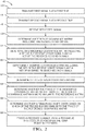
- Figure 2 is a flowchart diagram 40 that summarizes an example approach of using TDMA to achieve signal orthogonality in MIMO radars.
- the first transmitters 24 transmit the first signals at a first time.
- the second transmitters transmit the second signals at 44.
- the second transmission time of the second signals in this example is subsequent to the first transmission time.
- the TDMA technique of this example includes repeatedly transmitting the first and second signals at scheduled intervals.
- the receivers 28 receive the signals reflected from an object.
- the received signal at any of the receivers 28, which can be considered a (n,m) receiver array element, can be represented as a delayed transmitted signal with the following equation.
- s nm t A e j ⁇ R e j ⁇ ⁇ e j ⁇ D e j ⁇ S
- t is the discretized time
- ⁇ R , ⁇ ⁇ , ⁇ D are phase terms containing information about the detected object's range, angle, and velocity respectively
- ⁇ S is the phase term due to the sequential transmitter activation.
- the total delay in the signal represented in equation (1) includes four terms. Each of these terms provides information related to the target or detected object.
- the first delay ⁇ R is due to the distance between the reference point of the array of receivers 28 and the object and can be used to compute the object range.
- the second delay ⁇ ⁇ is the result of the position of the receiver 28 with respect to the reference point of the receiver array.
- the second delay ⁇ ⁇ is used to compute the target angle.
- the third delay ⁇ D is a consequence of a moving object or a moving platform and is useful to determine the object's velocity.
- the ⁇ S delay is due to the TDMA sequential transmitter activation.
- the processor 30 is configured to determine whether ⁇ S exists and to estimate ⁇ S for proper data analysis.
- the TDMA strategy includes activating the second transmitters 26 at one-half the pulse repetition interval of the first transmitters 24.
- ⁇ S to be represented by the following equation.
- ⁇ s 2 ⁇ 2 v ⁇ T
- the pulse repetition interval is 2T
- ⁇ denotes the wavelength
- v is the object's true velocity.
- the following equation describes that velocity.
- ⁇ S phase term introduces a phase shift of 0 or 180 degrees depending on the target's true velocity v. Since the target's velocity is not known a priori, the processor 30 is configured to estimate this phase shift for proper data analysis.
- the processor determines a reference covariance matrix including the received first signals at 48.
- Figure 3 schematically shows received signals at 50.
- the illustration includes 256 received signals representing each of thirty-two receivers 28 receiving a reflected first signal from each of four first transmitters 24 and a reflected second signal from each of four second transmitters 26.
- the received first signals are included in a reference set enclosed in the box 52. In this example all of the received first signals from a single first transmission time are included in the reference set.
- the processor 30 determines the reference covariance matrix using the first signals in the reference set 52.
- the processor determines an unmodified covariance matrix including at least some of the received first signals and at least some of the received second signals.
- a set of the received first signals enclosed in the box 56 in Figure 3 is included in the unmodified covariance matrix.
- This set 56 is a subset of the received first signals and can be represented by Y 1 .
- the unmodified covariance matrix also includes a set of the received second signals enclosed in the box 58.
- This set of second signals is a subset of all of the received second signals and can be represented by Y 2 .
- the unmodified covariance matrix can be represented by R xy of matrix [Y 1 ,Y 2 ].
- the processor 30 determines a modified covariance matrix using the first signals in Y 1 and a modified version of the set 58 of second signals.
- the processor 30 determines modified values of the second signals in the set 58 by multiplying each by -1. That set of modified values can be represented as - Y 2 .
- the modified covariance matrix determined at 60 can be represented by R xy' of matrix [Y 1 ,-Y 2 ].
- the processor 30 determines respective traces of the covariance matrices.
- the processor uses a relationship between the covariance matrices as basis to determine whether a TDMA or transmission timing phase shift ⁇ S exists.
- the processor 30 determines at 64 which of R xy or R xy' is more similar to the reference covariance matrix.
- the processor 30 determines whether a TDMA phase shift exists based on which of the traces is more similar to the trace of the reference covariance matrix. If the trace of the modified covariance matrix is more similar to the reference covariance matrix that indicates that the transmission timing phase shift does exist. If, on the other hand, the trace of the unmodified covariance matrix is more similar to the reference covariance matrix that indicates that the transmission timing phase shift does not exist.
- the processor 30 is configured to process the received signals based on a technique that accounts for the existence or absence of a transmission timing phase shift ⁇ S at 68.
- a technique that accounts for the existence or absence of a transmission timing phase shift ⁇ S at 68 In this example, when there is no phase shift the fourth phase term of equation (1) is eliminated and signal processing to determine the object's range, angle and Doppler velocity proceeds without ⁇ S .
- the processor includes a 180 degree shift value for ⁇ S in equation (1).
- the example embodiment facilitates using cost-effective TDMA signaling techniques without difficulties or errors otherwise associated with introducing a TDMA phase shift between signals.
- the disclosed system and method improve object detection and tracking efficiency and accuracy.
Landscapes
- Engineering & Computer Science (AREA)
- Radar, Positioning & Navigation (AREA)
- Remote Sensing (AREA)
- Physics & Mathematics (AREA)
- General Physics & Mathematics (AREA)
- Computer Networks & Wireless Communication (AREA)
- Electromagnetism (AREA)
- Multimedia (AREA)
- Computer Vision & Pattern Recognition (AREA)
- Theoretical Computer Science (AREA)
- Radar Systems Or Details Thereof (AREA)
Abstract
Description
- A variety of scenarios require signal handling. For example, radar systems and wireless communication systems include over-the-air signaling. One challenge associated with such systems is using multiple signals to increase information regarding detected objects while avoiding processing difficulties introduced by using multiple signals. For example, it is necessary for different signals to be orthogonal so that they can be individually detected and processed. One way of achieving orthogonality involves time division multiplexing (TDMA) in which signal transmissions are separated in time.
- While TDMA can be an efficient way of increasing the number of signals available for object detection and analysis, TDMA techniques may introduce signaling errors that have to be addressed to provide accurate detection information. For example, TDMA may introduce an additional phase shift based on the difference in transmission timing and such a phase shift could skew object detection information if it is not properly recognized or its influence is not removed from the received detection signal processing techniques. When detecting moving objects TDMA-based phase shifts are related to the unknown velocity of the moving object, which increases the difficulties associated with processing detection signals including such a phase shift.
- An illustrative example object detection system includes a plurality of first transmitters that respectively transmit a first signal at a first time, a plurality of second transmitters that respectively transmit a second signal at a second time, a plurality of receivers that receive the signals, and a processor that is configured to determine whether a transmission timing phase shift exists between the received first signals and the received second signals based on a relationship between matrices including the received signals.
- An illustrative example object detection method includes transmitting first signals at a first time from a plurality of first transmitters, transmitting second signals at a second time from a plurality of second transmitters, receiving the signals at a plurality of receivers, and determining whether a transmission timing phase shift exists between the received first signals and the received second signals based on a relationship between matrices including the received signals.
- Various features and advantages of at least one disclosed example embodiment will become apparent to those skilled in the art from the following detailed description. The drawings that accompany the detailed description can be briefly described as follows.
-
-
Figure 1 diagrammatically illustrates an object detection system designed according to an embodiment of this invention. -
Figure 2 is a flow chart diagram summarizing an example technique designed according to an embodiment of this invention. -
Figure 3 schematically illustrates matrices useful in an embodiment of this invention. - Embodiments of this invention allow for effective and accurate object detection when signals, such as RADAR, are transmitted using time division multiplexing (TDMA). Any phase shift introduced by TDMA can be detected and effectively removed from the signal processing based on determining a relationship between matrices that include the received signals. In an example embodiment, a relationship between traces of covariance matrices including the received signals indicates whether a TDMA phase shift exists and received signals can be processed based on that information.
-
Figure 1 schematically illustrates anobject detection system 20 supported on avehicle 22. Thesystem 20 includes a plurality offirst transmitters 24 that transmit respective first signals at a first time. A plurality ofsecond transmitters 26 respectively transmit second signals at a second time. The first and second signals are transmitted using TDMA. In the illustrated example embodiment the signals are linear frequency-modulated continuous wave signals, such as those typically used for automotive RADAR. Other signal types are used in some embodiments. - The
system 20 includes a plurality ofreceivers 28 that receive the first and second signals after those signals reflect off an object in a vicinity or pathway of thevehicle 22.Figure 1 shows twofirst transmitters 24, twosecond transmitters 26 and fourreceivers 28 but the illustrated embodiment includes more of each. One example embodiment of thesystem 20 includes fourfirst transmitters 24, foursecond transmitters 26 and thirty-tworeceivers 28. - A processor 30 is configured to process the received signals to make determinations regarding a detected or tracked object, such as the range, angle and Doppler velocity of the object. The processor 30 is configured to compensate for a transmission timing phase shift that may exist between the received first signals and the received second signals. The processor 30 determines whether a transmission phase shift exists based on a relationship between matrices that include the received signals.
- The processor includes at least one computing device, such as a microprocessor, and memory. The processor 30 may be a dedicated device or component or be realized through part of an existing controller or processor on the
vehicle 22 that is also used for other purposes. Those skilled in the art who have the benefit of this description will realize what arrangement of a processor, transmitters and receivers will meet their particular needs. -
Figure 2 is a flowchart diagram 40 that summarizes an example approach of using TDMA to achieve signal orthogonality in MIMO radars. At 42, thefirst transmitters 24 transmit the first signals at a first time. The second transmitters transmit the second signals at 44. The second transmission time of the second signals in this example is subsequent to the first transmission time. The TDMA technique of this example includes repeatedly transmitting the first and second signals at scheduled intervals. - At 46, the
receivers 28 receive the signals reflected from an object. The received signal at any of thereceivers 28, which can be considered a (n,m) receiver array element, can be represented as a delayed transmitted signal with the following equation.
- The total delay in the signal represented in equation (1) includes four terms. Each of these terms provides information related to the target or detected object. The first delay ϕR is due to the distance between the reference point of the array of
receivers 28 and the object and can be used to compute the object range. The second delay ϕθ is the result of the position of thereceiver 28 with respect to the reference point of the receiver array. The second delay ϕθ is used to compute the target angle. The third delay ϕD is a consequence of a moving object or a moving platform and is useful to determine the object's velocity. The ϕS delay is due to the TDMA sequential transmitter activation. The processor 30 is configured to determine whether ϕS exists and to estimate ϕS for proper data analysis. - In the example embodiment the TDMA strategy includes activating the
second transmitters 26 at one-half the pulse repetition interval of thefirst transmitters 24. This allows for ϕS to be represented by the following equation.


- Based on equation (4), it can be observed that the ϕS phase term introduces a phase shift of 0 or 180 degrees depending on the target's true velocity v. Since the target's velocity is not known a priori, the processor 30 is configured to estimate this phase shift for proper data analysis.
- In
Figure 2 , the processor determines a reference covariance matrix including the received first signals at 48.Figure 3 schematically shows received signals at 50. The illustration includes 256 received signals representing each of thirty-tworeceivers 28 receiving a reflected first signal from each of fourfirst transmitters 24 and a reflected second signal from each of foursecond transmitters 26. The received first signals are included in a reference set enclosed in thebox 52. In this example all of the received first signals from a single first transmission time are included in the reference set. The processor 30 determines the reference covariance matrix using the first signals in the reference set 52. - At 54 in
Figure 2 , the processor determines an unmodified covariance matrix including at least some of the received first signals and at least some of the received second signals. In this example, a set of the received first signals enclosed in thebox 56 inFigure 3 is included in the unmodified covariance matrix. This set 56 is a subset of the received first signals and can be represented by Y1. The unmodified covariance matrix also includes a set of the received second signals enclosed in thebox 58. This set of second signals is a subset of all of the received second signals and can be represented by Y2. In this example, the unmodified covariance matrix can be represented by Rxy of matrix [Y1,Y2]. - At 60 in
Figure 2 , the processor 30 determines a modified covariance matrix using the first signals in Y1 and a modified version of theset 58 of second signals. In this example, the processor 30 determines modified values of the second signals in theset 58 by multiplying each by -1. That set of modified values can be represented as -Y2. The modified covariance matrix determined at 60 can be represented by Rxy' of matrix [Y1,-Y2]. - In this example, the modified covariance matrix includes using -1 as a factor applied to the received second signals in the
set 58 because ϕS is part of an exponential function. Accordingly, Euler's identity indicates that the received signal is effectively multiplied by 1 if there is no transmission timing phase shift and multiplied by -1 if there is such a phase shift (i.e., ejϕs = e j(4π (vm /λ)T+lπ) = (-1) le j4π (vm /λ)T ). - At 62, the processor 30 determines respective traces of the covariance matrices. The processor uses a relationship between the covariance matrices as basis to determine whether a TDMA or transmission timing phase shift ϕS exists.
- A covariance matrix of an NxN square matrix X is defined as RXX , and its trace value can be computed in a known manner as

- In this example, the processor 30 determines at 64 which of Rxy or Rxy' is more similar to the reference covariance matrix. At 66, the processor 30 determines whether a TDMA phase shift exists based on which of the traces is more similar to the trace of the reference covariance matrix. If the trace of the modified covariance matrix is more similar to the reference covariance matrix that indicates that the transmission timing phase shift does exist. If, on the other hand, the trace of the unmodified covariance matrix is more similar to the reference covariance matrix that indicates that the transmission timing phase shift does not exist.
- The processor 30 is configured to process the received signals based on a technique that accounts for the existence or absence of a transmission timing phase shift ϕS at 68. In this example, when there is no phase shift the fourth phase term of equation (1) is eliminated and signal processing to determine the object's range, angle and Doppler velocity proceeds without ϕS. On the other hand when ϕS exists, the processor includes a 180 degree shift value for ϕS in equation (1).
- The example embodiment facilitates using cost-effective TDMA signaling techniques without difficulties or errors otherwise associated with introducing a TDMA phase shift between signals. The disclosed system and method improve object detection and tracking efficiency and accuracy.
- The preceding description is exemplary rather than limiting in nature. Variations and modifications to the disclosed examples may become apparent to those skilled in the art that do not necessarily depart from the essence of this invention. The scope of legal protection given to this invention can only be determined by studying the following claims.
Claims (15)
- An object detection system (20), comprising:a plurality of first transmitters (24) that respectively transmit a first signal at a first time;a plurality of second transmitters (26) that respectively transmit a second signal at a second time;a plurality of receivers (28) that receive the signals; anda processor (30) that is configured to determine whether a transmission timing phase shift exists between the received first signals and the received second signals based on a relationship between matrices including the received signals,wherein the signals in particular comprise RADAR signals; andthe receivers (28) receive the signals after the signals reflect off an object.
- The object detection system (20) of claim 1, wherein the matrices comprise covariance matrices and the processor (30) is configured to
determine a reference covariance matrix of the received first signals;
determine an unmodified covariance matrix including at least part of the received first signals and at least part of the received second signals;
determine a set of modified second signal values for the part of the received second signals multiplied by -1;
determine a modified covariance matrix including the part of the received first signals and the set of modified second signal values; and
determine the relationship between the matrices based on (i) a relationship between the reference covariance matrix and the unmodified covariance matrix and (ii) a relationship between the reference covariance matrix and the modified covariance matrix. - The object detection system (20) of claim 2, wherein the processor (30) is configured to
determine a reference trace T of the reference covariance matrix;
determine a trace Tu of the unmodified covariance matrix;
determine a trace Tm of the modified covariance matrix;
determine the relationship between the reference covariance matrix and the unmodified covariance matrix based on a relationship between the reference trace T and the trace Tu; and
determine the relationship between the reference covariance matrix and the modified covariance matrix based on a relationship between the reference trace T and the trace Tm. - The object detection system (20) of claim 3, wherein the processor (30) is configured to
determine whether the reference trace T is more similar to the trace Tu or the trace Tm; and
determine whether the transmission timing phase shift exists based on which of the traces Tu or Tm is more similar to the reference trace T. - The object detection system (20) of claim 4, wherein the processor (30) is configured to
determine that the transmission timing phase shift exists when the reference trace T is more similar to the trace Tm than the trace Tu; and
determine that the transmission timing phase shift does not exist when the reference trace T is more similar to the trace Tu than the trace Tm,
wherein the processor (30) is in particular configured to use a phase shift value of 180° for processing at least some of the received signals when the transmission timing phase shift exists. - The object detection system (20) of any of claims 2 - 5, wherein
there are four first transmitters (24);
there are four second transmitters (26);
there are thirty-two receivers (28);
there are one hundred twenty-eight received first signals in the reference covariance matrix;
there are sixty-four received first signals in the part of the received first signals; and
there are sixty-four received second signals in the part of the received second signals. - The object detection system (20) of any of claims 1 - 6, wherein
the matrices comprise covariance matrices including at least some of the received signals;
the processor (30) is configured to determine traces of the covariance matrices; and
the relationship between the matrices comprises a relationship between the traces of the covariance matrices. - The object detection system (20) of claim 7, wherein the processor (30) is configured to use a phase shift value of 180° for processing at least some of the received signals when the transmission timing phase shift exists.
- An object detection method, comprising:transmitting first signals at a first time from a plurality of first transmitters (24);transmitting second signals at a second time from a plurality of second transmitters (26);receiving the signals at a plurality of receivers (28); anddetermining whether a transmission timing phase shift exists between the received first signals and the received second signals based on a relationship between matrices including the received signals.
- The method of claim 9, wherein the matrices comprise covariance matrices and the method comprises
determining a reference covariance matrix of the received first signals;
determining an unmodified covariance matrix including at least part of the received first signals and at least part of the received second signals;
determining a set of modified second signal values for the part of the received second signals multiplied by -1;
determining a modified covariance matrix including the part of the received first signals and the set of modified second signal values; and
determining the relationship between the matrices based on (i) a relationship between the reference covariance matrix and the unmodified covariance matrix and (ii) a relationship between the reference covariance matrix and the modified covariance matrix. - The method of claim 10, comprising
determining a reference trace T of the reference covariance matrix;
determining a trace Tu of the unmodified covariance matrix;
determining a trace Tm of the modified covariance matrix;
determining the relationship between the reference covariance matrix and the unmodified covariance matrix based on a relationship between the reference trace T and the trace Tu; and
determining the relationship between the reference covariance matrix and the modified covariance matrix based on a relationship between the reference trace T and the trace Tm,
the method in particular comprising:determining whether the reference trace T is more similar to the trace Tu or the trace Tm; anddetermining whether the transmission timing phase shift exists based on which of the traces Tu or Tm is more similar to the reference trace T. - The method of claim 11, comprising
determining that the transmission timing phase shift exists when the reference trace T is more similar to the trace Tm than the trace Tu; and
determining that the transmission timing phase shift does not exist when the reference trace T is more similar to the trace Tu than the trace Tm,
the method in particular comprising using a phase shift value of 180° for processing at least some of the received signals when the transmission timing phase shift exists. - The method of claim 10, wherein
there are four first transmitters (24);
there are four second transmitters (26);
there are thirty-two receivers (28);
there are one hundred twenty-eight received first signals in the reference covariance matrix;
there are sixty-four received first signals in the part of the received first signals; and
there are sixty-four received second signals in the part of the received second signals,
wherein the signals in particular comprise RADAR signals; and
the receivers (28) receive the signals after the signals reflect off an object. - The method of claim 9, wherein
the matrices comprise covariance matrices including at least some of the received signals;
the method includes determining traces of the covariance matrices; and
the relationship between the matrices comprises a relationship between the traces of the covariance matrices. - The method of claim 14, comprising using a phase shift value of 180° for processing at least some of the received signals when the transmission timing phase shift exists.
Applications Claiming Priority (1)
| Application Number | Priority Date | Filing Date | Title |
|---|---|---|---|
| US15/988,150 US10281572B1 (en) | 2018-05-24 | 2018-05-24 | Phase correction for object detection including TDMA |
Publications (1)
| Publication Number | Publication Date |
|---|---|
| EP3572830A1 true EP3572830A1 (en) | 2019-11-27 |
Family
ID=66333946
Family Applications (1)
| Application Number | Title | Priority Date | Filing Date |
|---|---|---|---|
| EP19175387.0A Pending EP3572830A1 (en) | 2018-05-24 | 2019-05-20 | Phase correction for object detection including tdma |
Country Status (3)
| Country | Link |
|---|---|
| US (1) | US10281572B1 (en) |
| EP (1) | EP3572830A1 (en) |
| CN (1) | CN110531349B (en) |
Families Citing this family (1)
| Publication number | Priority date | Publication date | Assignee | Title |
|---|---|---|---|---|
| US11194040B2 (en) | 2018-07-17 | 2021-12-07 | Aptiv Technologies Limited | Slow time frequency division multiplexing with binary phase shifters |
Citations (3)
| Publication number | Priority date | Publication date | Assignee | Title |
|---|---|---|---|---|
| DE102008061932A1 (en) * | 2008-12-12 | 2010-07-01 | Astyx Gmbh | Imaging radar sensor with digital beam shaping and synthetic magnification of the antenna aperture |
| EP3147685A1 (en) * | 2015-09-22 | 2017-03-29 | Autoliv Development AB | A vehicle synthetic aperture radar system |
| WO2018071077A2 (en) * | 2016-07-09 | 2018-04-19 | Texas Instruments Incorporated | Methods and apparatus for velocity detection in mimo radar including velocity ambiguity resolution |
Family Cites Families (7)
| Publication number | Priority date | Publication date | Assignee | Title |
|---|---|---|---|---|
| US7068219B2 (en) * | 2004-06-10 | 2006-06-27 | Harris Corporation | Communications system including phased array antenna providing nulling and related methods |
| US20080074307A1 (en) * | 2006-05-17 | 2008-03-27 | Olga Boric-Lubecke | Determining presence and/or physiological motion of one or more subjects within a doppler radar system |
| US7541955B2 (en) * | 2006-09-26 | 2009-06-02 | Teac Corporation | A/D conversion circuit and optical disk drive |
| US7639171B2 (en) | 2007-09-27 | 2009-12-29 | Delphi Technologies, Inc. | Radar system and method of digital beamforming |
| US9541638B2 (en) * | 2014-11-11 | 2017-01-10 | Nxp B.V. | MIMO radar system |
| US9846228B2 (en) * | 2016-04-07 | 2017-12-19 | Uhnder, Inc. | Software defined automotive radar systems |
| CN107390208B (en) * | 2017-06-26 | 2020-10-30 | 桂林电子科技大学 | A Frequency Diversity Array Radar Communication Integration Method |
-
2018
- 2018-05-24 US US15/988,150 patent/US10281572B1/en active Active
-
2019
- 2019-05-20 EP EP19175387.0A patent/EP3572830A1/en active Pending
- 2019-05-23 CN CN201910432108.0A patent/CN110531349B/en active Active
Patent Citations (3)
| Publication number | Priority date | Publication date | Assignee | Title |
|---|---|---|---|---|
| DE102008061932A1 (en) * | 2008-12-12 | 2010-07-01 | Astyx Gmbh | Imaging radar sensor with digital beam shaping and synthetic magnification of the antenna aperture |
| EP3147685A1 (en) * | 2015-09-22 | 2017-03-29 | Autoliv Development AB | A vehicle synthetic aperture radar system |
| WO2018071077A2 (en) * | 2016-07-09 | 2018-04-19 | Texas Instruments Incorporated | Methods and apparatus for velocity detection in mimo radar including velocity ambiguity resolution |
Non-Patent Citations (1)
| Title |
|---|
| ROOS FABIAN ET AL: "Enhancement of Doppler Unambiguity for Chirp-Sequence Modulated TDM-MIMO Radars", 2018 IEEE MTT-S INTERNATIONAL CONFERENCE ON MICROWAVES FOR INTELLIGENT MOBILITY (ICMIM), IEEE, 15 April 2018 (2018-04-15), pages 1 - 4, XP033391296, DOI: 10.1109/ICMIM.2018.8443352 * |
Also Published As
| Publication number | Publication date |
|---|---|
| US10281572B1 (en) | 2019-05-07 |
| CN110531349B (en) | 2023-03-28 |
| CN110531349A (en) | 2019-12-03 |
Similar Documents
| Publication | Publication Date | Title |
|---|---|---|
| CN110161504B (en) | Vehicle radar system for solving Doppler shift and using method thereof | |
| US10852393B2 (en) | Method of calibrating a radar system | |
| US10830869B2 (en) | Vehicle radar system and method of calibrating the same | |
| CN110431437B (en) | Method and equipment for obtaining the lateral relative velocity component of a radar target | |
| US12345802B2 (en) | Doppler processing in frequency-modulated continuous wave radar systems using dither | |
| US9910150B2 (en) | Method, antenna array, radar system and vehicle | |
| JP7252052B2 (en) | MIMO radar device and signal processing method | |
| US10823846B2 (en) | Object detection method and object detection device | |
| CN113406641B (en) | Method for determining direction information | |
| US8115668B2 (en) | Object detecting apparatus for vehicle | |
| US10746861B2 (en) | Apparatus for detection and ranging | |
| CN104795641B (en) | Antenna arrangement, radar system, vehicle and method | |
| EP3451015B1 (en) | Method and apparatus for detecting object using radar of vehicle | |
| US20180156911A1 (en) | Direct doppler-free velocity measurement in linear frequency modulation radar | |
| CN118962657A (en) | Slow Time-Frequency Division Multiplexing Using Binary Phase Shifters | |
| CN115244418A (en) | Method for operating a radar system | |
| US10281572B1 (en) | Phase correction for object detection including TDMA | |
| CN112526496A (en) | Measurement information acquisition method, device and equipment | |
| US20240094376A1 (en) | Doppler radar resolution based on inertial measurement unit of vehicle | |
| CN114791602A (en) | Blurring mitigation in public fields of view based on radar systems | |
| RU2567243C1 (en) | Method of identifying aerial targets | |
| EP3454076B1 (en) | Mimo detector device useful for automated vehicles | |
| EP3705904A1 (en) | Removing interference from signals received by detectors installed on a vehicle | |
| EP4170377A1 (en) | Radar apparatus and method with content embedded in the radar signal | |
| US11360206B2 (en) | Detection device and detection method thereof |
Legal Events
| Date | Code | Title | Description |
|---|---|---|---|
| PUAI | Public reference made under article 153(3) epc to a published international application that has entered the european phase |
Free format text: ORIGINAL CODE: 0009012 |
|
| STAA | Information on the status of an ep patent application or granted ep patent |
Free format text: STATUS: THE APPLICATION HAS BEEN PUBLISHED |
|
| AK | Designated contracting states |
Kind code of ref document: A1 Designated state(s): AL AT BE BG CH CY CZ DE DK EE ES FI FR GB GR HR HU IE IS IT LI LT LU LV MC MK MT NL NO PL PT RO RS SE SI SK SM TR |
|
| AX | Request for extension of the european patent |
Extension state: BA ME |
|
| STAA | Information on the status of an ep patent application or granted ep patent |
Free format text: STATUS: REQUEST FOR EXAMINATION WAS MADE |
|
| 17P | Request for examination filed |
Effective date: 20200529 |
|
| RBV | Designated contracting states (corrected) |
Designated state(s): AL AT BE BG CH CY CZ DE DK EE ES FI FR GB GR HR HU IE IS IT LI LT LU LV MC MK MT NL NO PL PT RO RS SE SI SK SM TR |
|
| STAA | Information on the status of an ep patent application or granted ep patent |
Free format text: STATUS: EXAMINATION IS IN PROGRESS |
|
| 17Q | First examination report despatched |
Effective date: 20211122 |
|
| RAP3 | Party data changed (applicant data changed or rights of an application transferred) |
Owner name: APTIV TECHNOLOGIES LIMITED |
|
| RAP1 | Party data changed (applicant data changed or rights of an application transferred) |
Owner name: APTIV TECHNOLOGIES AG |
|
| RAP3 | Party data changed (applicant data changed or rights of an application transferred) |
Owner name: APTIV TECHNOLOGIES AG |
|
| GRAP | Despatch of communication of intention to grant a patent |
Free format text: ORIGINAL CODE: EPIDOSNIGR1 |
|
| STAA | Information on the status of an ep patent application or granted ep patent |
Free format text: STATUS: GRANT OF PATENT IS INTENDED |
|
| RIC1 | Information provided on ipc code assigned before grant |
Ipc: G01S 7/41 20060101AFI20260227BHEP Ipc: G01S 13/52 20060101ALI20260227BHEP Ipc: G01S 13/524 20060101ALI20260227BHEP Ipc: G01S 13/536 20060101ALI20260227BHEP Ipc: G01S 13/931 20200101ALI20260227BHEP |
|
| INTG | Intention to grant announced |
Effective date: 20260317 |