EP3572694A1 - Sealing ring - Google Patents
Sealing ring Download PDFInfo
- Publication number
- EP3572694A1 EP3572694A1 EP19186461.0A EP19186461A EP3572694A1 EP 3572694 A1 EP3572694 A1 EP 3572694A1 EP 19186461 A EP19186461 A EP 19186461A EP 3572694 A1 EP3572694 A1 EP 3572694A1
- Authority
- EP
- European Patent Office
- Prior art keywords
- sealing
- leg
- sealing ring
- body section
- ring according
- Prior art date
- Legal status (The legal status is an assumption and is not a legal conclusion. Google has not performed a legal analysis and makes no representation as to the accuracy of the status listed.)
- Granted
Links
Images




Classifications
-
- F—MECHANICAL ENGINEERING; LIGHTING; HEATING; WEAPONS; BLASTING
- F16—ENGINEERING ELEMENTS AND UNITS; GENERAL MEASURES FOR PRODUCING AND MAINTAINING EFFECTIVE FUNCTIONING OF MACHINES OR INSTALLATIONS; THERMAL INSULATION IN GENERAL
- F16J—PISTONS; CYLINDERS; SEALINGS
- F16J15/00—Sealings
- F16J15/02—Sealings between relatively-stationary surfaces
- F16J15/021—Sealings between relatively-stationary surfaces with elastic packing
- F16J15/022—Sealings between relatively-stationary surfaces with elastic packing characterised by structure or material
- F16J15/024—Sealings between relatively-stationary surfaces with elastic packing characterised by structure or material the packing being locally weakened in order to increase elasticity
- F16J15/025—Sealings between relatively-stationary surfaces with elastic packing characterised by structure or material the packing being locally weakened in order to increase elasticity and with at least one flexible lip
-
- F—MECHANICAL ENGINEERING; LIGHTING; HEATING; WEAPONS; BLASTING
- F16—ENGINEERING ELEMENTS AND UNITS; GENERAL MEASURES FOR PRODUCING AND MAINTAINING EFFECTIVE FUNCTIONING OF MACHINES OR INSTALLATIONS; THERMAL INSULATION IN GENERAL
- F16J—PISTONS; CYLINDERS; SEALINGS
- F16J15/00—Sealings
- F16J15/02—Sealings between relatively-stationary surfaces
- F16J15/06—Sealings between relatively-stationary surfaces with solid packing compressed between sealing surfaces
- F16J15/08—Sealings between relatively-stationary surfaces with solid packing compressed between sealing surfaces with exclusively metal packing
- F16J15/0887—Sealings between relatively-stationary surfaces with solid packing compressed between sealing surfaces with exclusively metal packing the sealing effect being obtained by elastic deformation of the packing
-
- F—MECHANICAL ENGINEERING; LIGHTING; HEATING; WEAPONS; BLASTING
- F16—ENGINEERING ELEMENTS AND UNITS; GENERAL MEASURES FOR PRODUCING AND MAINTAINING EFFECTIVE FUNCTIONING OF MACHINES OR INSTALLATIONS; THERMAL INSULATION IN GENERAL
- F16J—PISTONS; CYLINDERS; SEALINGS
- F16J15/00—Sealings
- F16J15/16—Sealings between relatively-moving surfaces
- F16J15/32—Sealings between relatively-moving surfaces with elastic sealings, e.g. O-rings
- F16J15/3204—Sealings between relatively-moving surfaces with elastic sealings, e.g. O-rings with at least one lip
- F16J15/3232—Sealings between relatively-moving surfaces with elastic sealings, e.g. O-rings with at least one lip having two or more lips
-
- F—MECHANICAL ENGINEERING; LIGHTING; HEATING; WEAPONS; BLASTING
- F16—ENGINEERING ELEMENTS AND UNITS; GENERAL MEASURES FOR PRODUCING AND MAINTAINING EFFECTIVE FUNCTIONING OF MACHINES OR INSTALLATIONS; THERMAL INSULATION IN GENERAL
- F16J—PISTONS; CYLINDERS; SEALINGS
- F16J15/00—Sealings
- F16J15/16—Sealings between relatively-moving surfaces
- F16J15/32—Sealings between relatively-moving surfaces with elastic sealings, e.g. O-rings
- F16J15/3204—Sealings between relatively-moving surfaces with elastic sealings, e.g. O-rings with at least one lip
- F16J15/3232—Sealings between relatively-moving surfaces with elastic sealings, e.g. O-rings with at least one lip having two or more lips
- F16J15/3236—Sealings between relatively-moving surfaces with elastic sealings, e.g. O-rings with at least one lip having two or more lips with at least one lip for each surface, e.g. U-cup packings
Definitions
- the present invention is directed to a sealing ring.
- Sealing rings also known as annular seals or O-rings, are widely used in industrial, automotive and machinery applications.
- Typical sealing rings are disclosed in U.S. Pat. Nos. 2,392,182 , 7,857,322 , 3,288,475 , 3,052,478 , 2,888,281 , 2,841,429 , 3,228,705 , 3,047,301 , 3,183,008 , 3,612,551 and 5,002,290 , U.S. Patent Application Publication No. 20130113165 , European Patent No. EP0806594 and Chinese Patent No. CN201047442 .
- a common prior art technique of accomplishing bidirectional sealing entails the use of two C-seals or spring energized seals facing back to back to handle pressure on the inner diameter or the outer diameter.
- Each seal must be positioned in a separate groove to provide support from the pressure on the opposite side of the seal. Positioning the seals in separate grooves is necessary because if the seals were positioned in the same groove, the seals would slide into each other thereby compromising the sealing integrity of both seals.
- the present invention is a sealing ring (10) having in a diametrical cross-section a body section (12) and a first pair of sealing legs (16) and (18) that extend outwardly from and are integral with the body section (12) and are angularly spaced apart by a first angle.
- the sealing ring (10) further includes in the diametrical cross-section a second pair of sealing legs (22) and (24) that extend outwardly from and are integral with the body section (12) and are spaced apart by a second angle.
- Each sealing leg (16), (18), (22) and (24) extends to a beveled end (28), (30), (32) and (34), respectively, which is configured to form a seal with a surface when the sealing ring (10) is subjected to compression or compressive stress.
- Sealing legs (16) and (24) are substantially coplanar. Sealing legs (18) and (22) are substantially coplanar. The plane in which sealing legs (16) and (24) are lying intersects the plane in which sealing legs (18) and (22) are lying. Stated another way, the plane of sealing legs (16) and (24) intersect the plane of sealing legs (18) and (22).
- Sealing ring (10) further comprises in the diametrical cross-section a first centering leg (40) that outwardly extends from and is integral with the body section (12) and is located between and angularly spaced apart from sealing leg (16) and sealing leg (22), and a second centering leg (44) that outwardly extends from and is integral with the body section (12) and is located between and angularly spaced apart from sealing leg (18) and sealing leg (24).
- the first and second centering legs (40) and (44) are substantially coplanar. When sealing ring (10) is positioned in annular groove (100), the first and second centering legs (40) and (44) center the sealing ring (10) and limit the lateral movement of the sealing ring (10).
- free height refers to the height of sealing ring 10 when the sealing ring 10 is not installed in any application and has no pressure or compressive forces thereon.
- sealing ring 10 has in a diametrical cross-section a body section 12 (see FIGS. 5A and 6A ).
- the center of body section 12 is indicated by reference number 14.
- Sealing ring 10 further includes in the diametrical cross-section a first pair of sealing legs 16 and 18 that extend outwardly from and are integral with the body section 12. Sealing legs 16 and 18 are angularly spaced apart by a first angle ⁇ 1. The geometrical configuration of sealing legs 16 and 18 form a channel or curved recess 20 between sealing legs 16 and 18.
- Sealing ring 10 further includes in the diametrical cross-section a second pair of sealing legs 22 and 24 that extend outwardly from and are integral with the body section 12. Sealing legs 22 and 24 are spaced apart by a second angle ⁇ 2 (see FIG. 5C ).
- the geometrical configuration of sealing legs 22 and 24 form a channel or curved recess 25 between sealing legs 22 and 24.
- Each sealing leg 16, 18, 22 and 24 extends to a beveled end 28, 30, 32 and 34, respectively.
- Each beveled end 28, 30, 32 and 34 is configured to form a seal with a surface when the sealing ring 10 is under pressure or subjected to compressive stress. As shown in FIG. 5B , each beveled end 28, 30, 32 and 34 is beveled in accordance with a predetermined bevel angle ⁇ which is discussed in detail in the ensuing description.
- Sealing leg 16 and sealing leg 24 are substantially coplanar. Sealing leg 18 and sealing leg 22 are substantially coplanar. The plane in which sealing legs 16 and 24 lie intersects the plane in which sealing legs 18 and 22 lie, wherein the point of intersection is at center 14 of body section 12.
- Sealing ring 10 further comprises in the diametrical cross-section a first centering leg 40 that outwardly extends from and is integral with body section 12 and is located between and angularly spaced apart from sealing legs 16 and 22. First centering leg 40 extends to end 42.
- the sealing ring 10 further comprises in the diametrical cross-section a second centering leg 44 that outwardly extends from and is integral with body section 12 and is located between and angularly spaced apart from sealing legs 18 and 24.
- Second centering leg 44 extends to end 46.
- the first and second centering legs 40 and 44 are substantially coplanar and lie in a plane that extends through center 14 of body section 12. Therefore, the plane in which sealing legs 16 and 24 lie and the plane in which sealing legs 18 and 22 lie intersect the plane in which centering sections 40 and 44 lie and all planes intersect each other at the center 14 of body section 12.
- Component 90 has an annularly extending channel or groove 100 and a wall or surface 102 within groove 100.
- Component 92 has a surface 104 that confronts groove 100.
- Sealing ring 10 is disposed within annularly extending groove 100. The functions of first and second centering legs 40 and 44 are to center the sealing ring 10 within groove 100 and to limit the lateral movement of the sealing ring 10 while positioned in groove 100.
- first angle ⁇ 1 is equal to second angle ⁇ 2.
- first angle ⁇ 1 and second angle ⁇ 2 are 105 degrees.
- First centering leg 40 is angularly spaced apart from the sealing leg 16 by a third angle ⁇ 3 and is angularly spaced apart from sealing leg 22 by a fourth angle ⁇ 4.
- third angle ⁇ 3 is equal to the fourth angle ⁇ 4.
- the third angle ⁇ 3 and fourth angle ⁇ 4 are 37 degrees.
- Second centering leg 44 is angularly spaced apart from sealing leg 18 by a fifth angle ⁇ 5 and angularly spaced apart from sealing leg 24 by a sixth angle ⁇ 6.
- fifth angle ⁇ 5 is equal to the sixth angle ⁇ 6.
- the fifth angle ⁇ 5 and sixth angle ⁇ 6 are 37 degrees.
- each beveled end 28, 30, 32 and 34 of each sealing leg 16, 18, 22 and 24, respectively is beveled in accordance with a predetermined bevel angle ⁇ .
- Sealing ring 10 is fabricated from a material that provides sealing ring 10 with a degree of resiliency such that when sealing ring 10 is subjected to compression or a compressive stress, there is a slight deformation in sealing legs 16, 18, 22 and 24 that causes the entire surface of each beveled end 28, 30, 32 and 34, respectively, to fully contact and become flush with the channel walls or other surfaces that confront the beveled ends 28, 30, 32 and 34. This is illustrated in FIG. 7 .
- Sealing ring 10 is disposed within a channel or groove 100 and is subjected to a compressive force created by components 90 and 92. As a result of this force and the degree of resiliency of sealing ring 10, the entire surface of each beveled end 28 and 30 fully contacts and becomes flush with surface 104 of component 92 and the entire surface of each beveled end 32 and 34 fully contacts and becomes flush with surface 102 of component 90 thereby creating a high-integrity seal between components 90 and 92.
- the predetermined bevel angle ⁇ is seven degrees.
- sealing ring 10 has a free height FH which is the maximum height of sealing ring 10 when sealing ring 10 is uninstalled and not subjected to any compression or compressive forces.
- the free height FH may be measured between edge 120 of sealing leg 18 and edge 122 of sealing leg 24.
- the ratio of bevel angle ⁇ to free height FH is within the range of about 70:1 to about 90:1.
- sealing ring 10 has a first outer diameter OD1 that is measured at end 42 of first centering leg 40.
- the ratio of first outer diameter OD1 to free height FH is within a predetermined range for a particular first outer diameter OD1.
- the ratio OD1/FH is within a range of about 0.112 to about 0.037.
- the ratio OD1/FH is within a range of about 0.046 to about 0.023.
- first outer diameters OD1 of 6.0 inches to 12.0 inches the ratio OD1/FH is within a range of about 0.028 to about 0.014. It is to be understood that these outer diameter OD1 dimensions and ratios may vary depending upon the application in which sealing ring 10 is used and the materials from which the sealing ring 10 is fabricated.
- sealing ring 10 has a second outer diameter OD2 which is less than first outer diameter OD1.
- Second outer diameter OD2 may be measured at outer portion 50 of sealing leg 16 and may also be measured at outer portion 52 of sealing leg 22.
- the first outer diameter OD1 is about 1.0 inch and the second outer diameter OD2 is about 0.956 inch.
- sealing ring 10 has a first inner diameter ID1 that is measured at end 46 of second centering leg 44. Sealing ring 10 also has a second inner diameter ID2 that is greater than the first inner diameter ID1. Second inner diameter ID2 is measured at portion 60 of sealing leg 18 and may also be measured at portion 62 of sealing leg 24. In one embodiment, first inner diameter ID1 is about 0.60 inch and second inner diameter ID2 is about 0.644 inch.
- each sealing leg 16, 18, 22 and 24 has a thickness T1.
- thickness T1 is about 0.015 inch.
- First centering leg 40 and second centering leg 44 each have a thickness T2.
- thickness T2 is about 0.012 inch.
- Each sealing leg 16, 18, 22 and 24 has a length L1.
- length L1 is about 0.061 inch.
- Each centering leg 40 and 44 has a length L2.
- length L2 is about 0.067 inch.
- sealing ring 10 may be varied depending upon the application in which sealing ring 10 is to be used.
- sealing ring 10 is fabricated from alloys such as Inconel alloys and Hastelloy alloys. In other embodiments, sealing ring 10 may be fabricated from rubbers, elastomers, plastics and composites. In alternate embodiments, sealing ring 10 may be fabricated from other metals.
- sealing ring 10 allows sealing ring 10 to be used in situations wherein there are two sources of pressure, one on either side of sealing ring 10, wherein each source of pressure could be positive pressure or negative pressure.
- positive pressure are positive hydraulic pressure, hydrostatic pressure, pneumatic pressure or a positive vacuum pressure.
- the positive pressure would be on both the inner diameter and outer diameter of the sealing ring 10.
- An example of negative pressure is a negative vacuum pressure.
- Typical applications for sealing ring 10 include offshore drilling wells wherein there would be hydrostatic pressure on one side of sealing ring 10 and oil pressure on the other side of sealing ring 10.
- the pressure is on the inner and outer diameters to pressure-energize sealing ring 10.
- negative vacuum pressures the negative pressure may be on either side of sealing ring 10.
- sealing ring 10 An application wherein the negative pressure may be on either side of sealing ring 10 is a retort wherein there is vacuum pressure on the outer diameter or inner diameter and positive pressure on the opposite side of sealing ring 10.
- positive pressure is atmospheric pressure or higher pressure.
- Sealing ring 10 may also be used as a redundant seal that functions as a back-up seal in the event the first seal fails. Sealing ring 10 requires only a single groove, channel or cavity in contrast to the prior art C-seals or spring energized seals. Centering legs 40 and 44 locate sealing ring 10 relative to the channel, groove or cavity to prevent sealing ring 10 from sliding and the loss of sealing integrity with pressure or variations in pressure on the outer diameter or the inner diameter. Sealing ring 10 has sufficient stiffness to prevent seal leakage and to prevent sealing ring 10 from being de-energized.
- a sealing ring (10) having in a diametrical cross-section a body section (12), a first pair of sealing legs (16, 18) that extend outwardly from and are integral with the body section (12) and are angularly spaced apart by a first angle, and a second pair of sealing legs (22, 24) that extend outwardly from and are integral with the body section (12) and are spaced apart by a second angle, each sealing leg (16, 18, 22, 24) extending to a beveled end (28, 30, 32, 34), respectively, that is configured to form a seal with a surface when sealing ring (10) is under compressive force, the sealing legs (16) and (24) being substantially coplanar and the sealing legs (18) and (22) being substantially coplanar, wherein the plane of sealing legs (16) and (24) intersects the plane of sealing legs (18) and (22), the sealing ring (10) further comprising in the diametrical cross-section a first centering leg (40) that outwardly extends from and is integral with the body section (12) and is located
Landscapes
- Engineering & Computer Science (AREA)
- General Engineering & Computer Science (AREA)
- Mechanical Engineering (AREA)
- Sealing Devices (AREA)
- Gasket Seals (AREA)
Abstract
Description
- The present invention is directed to a sealing ring.
- Sealing rings, also known as annular seals or O-rings, are widely used in industrial, automotive and machinery applications. Typical sealing rings are disclosed in
U.S. Pat. Nos. 2,392,182 ,7,857,322 ,3,288,475 ,3,052,478 ,2,888,281 ,2,841,429 ,3,228,705 ,3,047,301 ,3,183,008 ,3,612,551 and5,002,290 ,U.S. Patent Application Publication No. 20130113165 , European Patent No.EP0806594 and Chinese Patent No.CN201047442 . - A common prior art technique of accomplishing bidirectional sealing entails the use of two C-seals or spring energized seals facing back to back to handle pressure on the inner diameter or the outer diameter. Each seal must be positioned in a separate groove to provide support from the pressure on the opposite side of the seal. Positioning the seals in separate grooves is necessary because if the seals were positioned in the same groove, the seals would slide into each other thereby compromising the sealing integrity of both seals.
- The present invention is a sealing ring (10) having in a diametrical cross-section a body section (12) and a first pair of sealing legs (16) and (18) that extend outwardly from and are integral with the body section (12) and are angularly spaced apart by a first angle. The sealing ring (10) further includes in the diametrical cross-section a second pair of sealing legs (22) and (24) that extend outwardly from and are integral with the body section (12) and are spaced apart by a second angle. Each sealing leg (16), (18), (22) and (24) extends to a beveled end (28), (30), (32) and (34), respectively, which is configured to form a seal with a surface when the sealing ring (10) is subjected to compression or compressive stress. Sealing legs (16) and (24) are substantially coplanar. Sealing legs (18) and (22) are substantially coplanar. The plane in which sealing legs (16) and (24) are lying intersects the plane in which sealing legs (18) and (22) are lying. Stated another way, the plane of sealing legs (16) and (24) intersect the plane of sealing legs (18) and (22). Sealing ring (10) further comprises in the diametrical cross-section a first centering leg (40) that outwardly extends from and is integral with the body section (12) and is located between and angularly spaced apart from sealing leg (16) and sealing leg (22), and a second centering leg (44) that outwardly extends from and is integral with the body section (12) and is located between and angularly spaced apart from sealing leg (18) and sealing leg (24). The first and second centering legs (40) and (44) are substantially coplanar. When sealing ring (10) is positioned in annular groove (100), the first and second centering legs (40) and (44) center the sealing ring (10) and limit the lateral movement of the sealing ring (10).
- Various embodiments of the present invention may incorporate one or more of these and other features described herein. A better understanding of the nature and advantages of the present invention may be gained by reference to the following detailed description and the accompanying drawings.
-
-
FIG. 1 is an isometric view of the sealing ring of the present invention; -
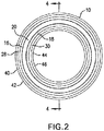
FIG. 2 is a top view of the sealing ring; -
FIG. 3 is a bottom view of the sealing ring; -
FIG. 4 is a cross-sectional view taken along line 4-4 inFIG. 2 ; -
FIG. 5A is an enlarged version of the view indicated byreference number 5A inFIG. 4 ; -
FIG. 5B is the same view asFIG. 5A , the view showing reference lines and other indicia to indicate angles and dimensions of various portions of the sealing ring; -
FIG. 5C is the same view asFIG. 5A , the view showing reference lines and other indicia to indicate angles and dimensions of various portions of the sealing ring; -
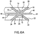
FIG. 6A is an enlarged version of the view indicated byreference number 6A inFIG. 4 ; -
FIG. 6B is the same view asFIG. 6A , the view showing reference lines and other indicia to indicate dimensions of various portions of the sealing ring; and -
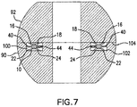
FIG. 7 is a cross-sectional view showing the sealing ring in use to create a seal between two components. - As used herein, the term "free height" refers to the height of sealing
ring 10 when thesealing ring 10 is not installed in any application and has no pressure or compressive forces thereon. - Referring now to
FIGS. 1-5A ,5B ,6A and6B , there is shown sealingring 10 according to the present invention.Sealing ring 10 has in a diametrical cross-section a body section 12 (seeFIGS. 5A and6A ). The center ofbody section 12 is indicated byreference number 14.Sealing ring 10 further includes in the diametrical cross-section a first pair ofsealing legs body section 12.Sealing legs sealing legs curved recess 20 betweensealing legs Sealing ring 10 further includes in the diametrical cross-section a second pair ofsealing legs body section 12.Sealing legs FIG. 5C ). The geometrical configuration ofsealing legs curved recess 25 betweensealing legs sealing leg beveled end end sealing ring 10 is under pressure or subjected to compressive stress. As shown inFIG. 5B , each beveledend -
Sealing leg 16 and sealingleg 24 are substantially coplanar.Sealing leg 18 and sealingleg 22 are substantially coplanar. The plane in which sealinglegs legs center 14 ofbody section 12.Sealing ring 10 further comprises in the diametrical cross-section afirst centering leg 40 that outwardly extends from and is integral withbody section 12 and is located between and angularly spaced apart from sealinglegs leg 40 extends toend 42. The sealingring 10 further comprises in the diametrical cross-section a second centeringleg 44 that outwardly extends from and is integral withbody section 12 and is located between and angularly spaced apart from sealinglegs leg 44 extends to end 46. The first and second centeringlegs center 14 ofbody section 12. Therefore, the plane in which sealinglegs legs sections center 14 ofbody section 12. - Referring to
FIG. 7 , there is shown an apparatus having two parts, components orsections Component 90 has an annularly extending channel or groove 100 and a wall orsurface 102 withingroove 100.Component 92 has asurface 104 that confrontsgroove 100. Sealingring 10 is disposed within annularly extendinggroove 100. The functions of first and second centeringlegs ring 10 withingroove 100 and to limit the lateral movement of the sealingring 10 while positioned ingroove 100. - Referring to
FIGS. 5B and5C , in accordance with the invention, first angle θ1 is equal to second angle θ2. In one embodiment, first angle θ1 and second angle θ2 are 105 degrees. First centeringleg 40 is angularly spaced apart from the sealingleg 16 by a third angle θ3 and is angularly spaced apart from sealingleg 22 by a fourth angle θ4. In accordance with the invention, third angle θ3 is equal to the fourth angle θ4. In one embodiment, the third angle θ3 and fourth angle θ4 are 37 degrees. Second centeringleg 44 is angularly spaced apart from sealingleg 18 by a fifth angle θ5 and angularly spaced apart from sealingleg 24 by a sixth angle θ6. In accordance with the invention, fifth angle θ5 is equal to the sixth angle θ6. In one embodiment, the fifth angle θ5 and sixth angle θ6 are 37 degrees. - Referring to
FIGS. 5A ,5B ,6A and6B , eachbeveled end leg ring 10 is fabricated from a material that provides sealingring 10 with a degree of resiliency such that when sealingring 10 is subjected to compression or a compressive stress, there is a slight deformation in sealinglegs beveled end FIG. 7 . Sealingring 10 is disposed within a channel or groove 100 and is subjected to a compressive force created bycomponents ring 10, the entire surface of eachbeveled end surface 104 ofcomponent 92 and the entire surface of eachbeveled end surface 102 ofcomponent 90 thereby creating a high-integrity seal betweencomponents - Referring to
FIG. 5B , sealingring 10 has a free height FH which is the maximum height of sealingring 10 when sealingring 10 is uninstalled and not subjected to any compression or compressive forces. The free height FH may be measured betweenedge 120 of sealingleg 18 andedge 122 of sealingleg 24. In one embodiment of the invention, the ratio of bevel angle ϕ to free height FH is within the range of about 70:1 to about 90:1. - As shown in
FIG. 6B , sealingring 10 has a first outer diameter OD1 that is measured atend 42 of first centeringleg 40. In one embodiment of the invention, the ratio of first outer diameter OD1 to free height FH is within a predetermined range for a particular first outer diameter OD1. For example, in one embodiment, for first outer diameters OD1 of about 1.0 inch to 3.0 inches, the ratio OD1/FH is within a range of about 0.112 to about 0.037. For first outer diameters OD1 of 3.0 inches to 6.0 inches, the ratio OD1/FH is within a range of about 0.046 to about 0.023. For first outer diameters OD1 of 6.0 inches to 12.0 inches, the ratio OD1/FH is within a range of about 0.028 to about 0.014. It is to be understood that these outer diameter OD1 dimensions and ratios may vary depending upon the application in which sealingring 10 is used and the materials from which the sealingring 10 is fabricated. - Referring to
FIG. 6B , sealingring 10 has a second outer diameter OD2 which is less than first outer diameter OD1. Second outer diameter OD2 may be measured atouter portion 50 of sealingleg 16 and may also be measured atouter portion 52 of sealingleg 22. In one embodiment, the first outer diameter OD1 is about 1.0 inch and the second outer diameter OD2 is about 0.956 inch. - Referring to
FIG. 6B , sealingring 10 has a first inner diameter ID1 that is measured atend 46 of second centeringleg 44. Sealingring 10 also has a second inner diameter ID2 that is greater than the first inner diameter ID1. Second inner diameter ID2 is measured atportion 60 of sealingleg 18 and may also be measured atportion 62 of sealingleg 24. In one embodiment, first inner diameter ID1 is about 0.60 inch and second inner diameter ID2 is about 0.644 inch. - Referring to
FIG. 5B , each sealingleg leg 40 and second centeringleg 44 each have a thickness T2. In one embodiment, thickness T2 is about 0.012 inch. Each sealingleg leg - It is to be understood that the foregoing dimensions of sealing
ring 10 may be varied depending upon the application in which sealingring 10 is to be used. - In a preferred embodiment, sealing
ring 10 is fabricated from alloys such as Inconel alloys and Hastelloy alloys. In other embodiments, sealingring 10 may be fabricated from rubbers, elastomers, plastics and composites. In alternate embodiments, sealingring 10 may be fabricated from other metals. - The design and configuration of sealing
ring 10 allows sealingring 10 to be used in situations wherein there are two sources of pressure, one on either side of sealingring 10, wherein each source of pressure could be positive pressure or negative pressure. Examples of positive pressure are positive hydraulic pressure, hydrostatic pressure, pneumatic pressure or a positive vacuum pressure. The positive pressure would be on both the inner diameter and outer diameter of the sealingring 10. An example of negative pressure is a negative vacuum pressure. Typical applications for sealingring 10 include offshore drilling wells wherein there would be hydrostatic pressure on one side of sealingring 10 and oil pressure on the other side of sealingring 10. For positive pressure sealing, the pressure is on the inner and outer diameters to pressure-energizesealing ring 10. For negative vacuum pressures, the negative pressure may be on either side of sealingring 10. An application wherein the negative pressure may be on either side of sealingring 10 is a retort wherein there is vacuum pressure on the outer diameter or inner diameter and positive pressure on the opposite side of sealingring 10. An example of positive pressure is atmospheric pressure or higher pressure. Sealingring 10 may also be used as a redundant seal that functions as a back-up seal in the event the first seal fails. Sealingring 10 requires only a single groove, channel or cavity in contrast to the prior art C-seals or spring energized seals. Centeringlegs ring 10 relative to the channel, groove or cavity to prevent sealingring 10 from sliding and the loss of sealing integrity with pressure or variations in pressure on the outer diameter or the inner diameter. Sealingring 10 has sufficient stiffness to prevent seal leakage and to prevent sealingring 10 from being de-energized. - It will be understood that many additional changes in the details, materials, steps and arrangement of parts, which have been herein described and illustrated in order to explain the nature of the invention, may be made by those skilled in the art within the principle and scope of the invention as expressed in the appended claims. Such modifications and variations that may be apparent to a person skilled in the art are intended to be included within the scope of this invention as defined by the accompanying claims.
The following items form part of the description: 1. A sealing ring (10) having in a diametrical cross-section a body section (12), a first pair of sealing legs (16, 18) that extend outwardly from and are integral with the body section (12) and are angularly spaced apart by a first angle, and a second pair of sealing legs (22, 24) that extend outwardly from and are integral with the body section (12) and are spaced apart by a second angle, each sealing leg (16, 18, 22, 24) extending to a beveled end (28, 30, 32, 34), respectively, that is configured to form a seal with a surface when sealing ring (10) is under compressive force, the sealing legs (16) and (24) being substantially coplanar and the sealing legs (18) and (22) being substantially coplanar, wherein the plane of sealing legs (16) and (24) intersects the plane of sealing legs (18) and (22), the sealing ring (10) further comprising in the diametrical cross-section a first centering leg (40) that outwardly extends from and is integral with the body section (12) and is located between and angularly spaced apart from sealing legs (16) and (22), and a second centering leg (44) that outwardly extends from and is integral with the body section (12) and is located between and angularly spaced apart from sealing legs (18) and (24), the first and second centering legs (40) and (44) being substantially coplanar, whereby when the sealing ring (10) is positioned within an annular groove (100), the first and second centering legs (40, 44) center the sealing ring (10) and limit the lateral movement of the sealing ring (10). - 2. The sealing ring (10) according to item 1 wherein the body section (12) has a center (14) at which the plane of sealing legs (16) and (24) intersects the plane of sealing legs (18) and (22).
- 3. The sealing ring (10) according to item 2 wherein the plane of the first and second centering legs (40) and (44) extends through the center (14) of body section (12).
- 4. The sealing ring (10) according to item 1 wherein the first angle is equal to the second angle.
- 5. The sealing ring (10) according to item 1 wherein the first centering leg (40) is angularly spaced apart from the sealing leg (16) by a third angle and the first centering leg (40) is angularly spaced apart from sealing leg (22) by a fourth angle.
- 6. The sealing ring (10) according to item 5 wherein the third angle is equal to the fourth angle.
- 7. The sealing ring (10) according to item 1 wherein the second centering leg (44) is angularly spaced apart from sealing leg (18) by a fifth angle and the second centering leg (44) is angularly spaced apart from sealing leg (24) by a sixth angle.
- 8. The sealing ring (10) according to item 7 wherein the fifth angle is equal to the sixth angle.
- 9. The sealing ring (10) according to item 1 wherein each beveled end (28, 30, 32, 34) of each sealing leg (16, 18, 22, 24), respectively, is beveled in accordance with a predetermined bevel angle.
- 10. The sealing ring (10) according to item 9 wherein the sealing ring (10) has a free height FH when the sealing ring (10) is uninstalled and wherein the ratio of the bevel angle to the free height FH is within a range of about 70:1 to about 90:1.
- 11. The sealing ring (10) according to
item 10 wherein first centering leg (40) extends to an end (42) and the second centering leg (44) extends to an end (46), and wherein the sealing ring (10) has an outer diameter OD1 that is measured at end (42) and wherein the ratio of the outer diameter OD1 to the free height FH is within a range of about 0.112 to about 0.037 when the outer diameter OD1 is within a range of about 1.0 inch to 3.0 inches. - 12. The sealing ring (10) according to
item 10 wherein first centering leg (40) extends to an end (42) and the second centering leg (44) extends to an end (46), and wherein the sealing ring (10) has an outer diameter OD1 that is measured at end (42) and wherein the ratio of the outer diameter OD1 to the free height FH is within a range of about 0.046 to about 0.023 when the outer diameter OD1 is within the range of 3.0 inches to 6.0 inches. - 13. The sealing ring (10) according to
item 10 wherein first centering leg (40) extends to an end (42) and the second centering leg (44) extends to an end (46), and wherein the sealing ring (10) has an outer diameter OD1 that is measured at end (42) and wherein the ratio of the outer diameter OD1 to the free height FH is within a range of about 0.028 to about 0.014 when the outer diameter OD1 is within the range of 6.0 inches to about 12.0 inches. - 14. The sealing ring (10) according to item 1 wherein the sealing seal (10) is fabricated from a material chosen from the group comprising rubbers, elastomers, metals, metal alloys, plastics and composites.
- 15. The sealing ring (10) according to item 1 wherein the sealing ring (10) is fabricated from a metal alloy chosen from the group comprising Inconel alloys and Hastelloy alloys.
Claims (15)
- A sealing ring, comprising:a body section comprising a center;a first sealing leg that extends from the body section;a second sealing leg that extends from the body section, wherein the first sealing leg and second sealing leg are angularly spaced apart by a first angle;a third sealing leg that extends from the body section; anda fourth sealing leg that extends from body section, wherein the third sealing leg and fourth sealing leg are angularly spaced apart by a second angle.
- The sealing ring according to claim 1, wherein the first angle is equal to the second angle.
- The sealing ring according to claim 1, wherein the first sealing leg and the fourth sealing leg are substantially coplanar, and wherein the second sealing leg and the third sealing leg are substantially coplanar.
- The sealing ring according to claim 3, wherein the plane in which the first sealing leg and the fourth sealing leg lie intersects the plane in which the third sealing leg and the second sealing leg lie.
- The sealing ring according to claim 4, wherein the planes intersect at the center of the body section.
- The sealing ring according to claim 1, wherein the first sealing leg and the second sealing leg form a first curved recess, and wherein the third sealing leg and the fourth sealing leg form a second curved recess.
- The sealing ring according to claim 1, wherein each sealing leg extends to a beveled end.
- The sealing ring according to claim 7, wherein when the sealing ring is disposed within an annularly extending channel or groove, the beveled ends form a seal with surfaces of the annularly extending channel or groove when the sealing ring is under pressure or subjected to a compressive force.
- The sealing ring according to claim 8, wherein slight deformation in the sealing legs causes the beveled ends to fully contact the surfaces of the annularly extending channel or groove.
- The sealing ring according to claim 1, further comprising: a first centering leg that extends from and is integral with the body section and is located between and angularly spaced apart from the first sealing leg and the third sealing leg; and a second centering leg that extends from and is integral with the body section and is located between and angularly spaced apart from the second sealing leg and the fourth sealing leg.
- The sealing ring according to claim 10, wherein the first centering leg and the second centering leg are substantially coplanar.
- The sealing ring according to claim 11, wherein when the sealing ring is disposed within an annularly extending channel or groove, the first centering leg and the second centering leg locate the sealing ring relative to the annularly extending channel or groove to prevent the loss of sealing integrity with variations in pressure.
- The sealing ring according to claim 1, wherein the ratio of an outer diameter of the sealing ring to a free height of the sealing ring is within a range of about 0.046 to about 0.023 when the outer diameter is within the range of 76,2 mm (3.0 inches) to about 152,4 mm (6.0 inches).
- The sealing ring according to claim 1, wherein the ratio of an outer diameter of the sealing ring to a free height of the sealing ring is within a range of about 0.028 to about 0.014, when the outer diameter is within the range of 152,4 mm (6.0 inches) to about 304,8 mm (12.0 inches).
- The sealing ring according to claim 1, wherein the sealing seal is fabricated from a material chosen from the group comprising rubbers, elastomers, metals, metal alloys, plastics, and composites.
Applications Claiming Priority (3)
| Application Number | Priority Date | Filing Date | Title |
|---|---|---|---|
| US14/485,429 US9551420B2 (en) | 2014-09-12 | 2014-09-12 | Sealing ring |
| EP15839956.8A EP3191745B1 (en) | 2014-09-12 | 2015-09-10 | Sealing ring |
| PCT/US2015/049335 WO2016040569A1 (en) | 2014-09-12 | 2015-09-10 | Sealing ring |
Related Parent Applications (1)
| Application Number | Title | Priority Date | Filing Date |
|---|---|---|---|
| EP15839956.8A Division EP3191745B1 (en) | 2014-09-12 | 2015-09-10 | Sealing ring |
Publications (2)
| Publication Number | Publication Date |
|---|---|
| EP3572694A1 true EP3572694A1 (en) | 2019-11-27 |
| EP3572694B1 EP3572694B1 (en) | 2023-10-25 |
Family
ID=55454338
Family Applications (2)
| Application Number | Title | Priority Date | Filing Date |
|---|---|---|---|
| EP19186461.0A Active EP3572694B1 (en) | 2014-09-12 | 2015-09-10 | Sealing ring |
| EP15839956.8A Active EP3191745B1 (en) | 2014-09-12 | 2015-09-10 | Sealing ring |
Family Applications After (1)
| Application Number | Title | Priority Date | Filing Date |
|---|---|---|---|
| EP15839956.8A Active EP3191745B1 (en) | 2014-09-12 | 2015-09-10 | Sealing ring |
Country Status (3)
| Country | Link |
|---|---|
| US (1) | US9551420B2 (en) |
| EP (2) | EP3572694B1 (en) |
| WO (1) | WO2016040569A1 (en) |
Families Citing this family (9)
| Publication number | Priority date | Publication date | Assignee | Title |
|---|---|---|---|---|
| EP3492783B1 (en) * | 2016-07-26 | 2024-12-18 | FMC Technologies Do Brasil LTDA | System comprising bi-directional face metal sealing seal that can be self-powered by pressure |
| CN106352181B (en) * | 2016-10-18 | 2020-12-22 | 杨顺立 | Bow-shaped ring sealing washer and bow-shaped ring sealing pipe connecting piece |
| US11499637B2 (en) | 2018-09-11 | 2022-11-15 | Caterpillar Inc. | Lip seal |
| JP1638480S (en) * | 2018-09-11 | 2019-08-05 | ||
| DE102018219779A1 (en) * | 2018-11-19 | 2020-05-20 | Zf Friedrichshafen Ag | Sealing device, electric machine and drive device |
| EP3948031A1 (en) * | 2019-03-29 | 2022-02-09 | ABB Schweiz AG | Joint, motor, industrial robot and method of installing a seal |
| WO2021016021A1 (en) * | 2019-07-19 | 2021-01-28 | S.P.M. Flow Control, Inc. | Novel high-pressure sealing ring with custom-shaped profile |
| JP7612635B2 (en) | 2022-05-30 | 2025-01-14 | 三菱電線工業株式会社 | Annular metal seal, annular metal seal mounting structure, and annular metal seal mounting method |
| CN119353422B (en) * | 2024-12-20 | 2025-03-18 | 温州东大压缩机科技有限公司 | Sealing packing assembly with multiple sealing structure for reciprocating compressor and manufacturing equipment thereof |
Citations (15)
| Publication number | Priority date | Publication date | Assignee | Title |
|---|---|---|---|---|
| US2392182A (en) | 1943-06-19 | 1946-01-01 | Crane Packing Co | Piston construction |
| US2841429A (en) | 1955-10-04 | 1958-07-01 | Parker Hannifin Corp | Sealing ring and joint |
| US2888281A (en) | 1957-01-23 | 1959-05-26 | Chicago Rawhide Mfg Co | Self-compensating seal |
| US3047301A (en) | 1960-02-12 | 1962-07-31 | Lockheed Aircraft Corp | Static sealing assembly |
| US3052478A (en) | 1959-09-16 | 1962-09-04 | Prec Associates Inc | Sealing ring |
| US3183008A (en) | 1963-03-04 | 1965-05-11 | Allegheny Plastics | X-seal |
| US3228705A (en) | 1962-03-13 | 1966-01-11 | Dowty Seals Ltd | Rotary sealing devices |
| US3288475A (en) | 1962-06-06 | 1966-11-29 | Joint Francais | Toric packing |
| US3612551A (en) | 1969-11-06 | 1971-10-12 | Trw Inc | Bidirectional lip seal |
| US5002290A (en) | 1989-03-07 | 1991-03-26 | Procal | Static seal |
| EP0806594A1 (en) | 1996-04-30 | 1997-11-12 | Teruaki Masuoka | O-ring of a multi-lobular cross section |
| US20070287317A1 (en) * | 2006-06-13 | 2007-12-13 | Reum Rex J | Independent Leg Seal |
| CN201047442Y (en) | 2007-05-25 | 2008-04-16 | 广州机械科学研究院 | X-shape combined seal ring |
| US7857322B2 (en) | 2006-03-23 | 2010-12-28 | Carl Freudenberg Kg | Sealing ring |
| US20130113165A1 (en) | 2011-03-23 | 2013-05-09 | Kayaba Industry Co., Ltd. | Piston bearing structure for fluid pressure cylinder |
Family Cites Families (10)
| Publication number | Priority date | Publication date | Assignee | Title |
|---|---|---|---|---|
| US3047300A (en) * | 1959-07-01 | 1962-07-31 | Lockheed Aircraft Corp | Metal sealing assembly |
| FR1595913A (en) * | 1968-11-22 | 1970-06-15 | ||
| US3550990A (en) * | 1969-06-17 | 1970-12-29 | Minnesota Rubber Co | Sealing device |
| DE1939195A1 (en) * | 1969-08-01 | 1971-02-11 | Maschf Augsburg Nuernberg Ag | Centering labyrinth seal |
| NL164945C (en) * | 1977-11-23 | 1981-02-16 | Vredestein Nv | SEALING PROFILE FOR A SUN-TUNNEL. |
| GB2163497B (en) * | 1984-08-22 | 1987-09-16 | Terence Peter Nicholson | Ring seals |
| US4787642A (en) * | 1987-04-27 | 1988-11-29 | Seaboard Wellhead, Inc. | X-shaped high pressure sealing structure |
| BR9104213A (en) * | 1991-09-25 | 1993-04-20 | Aco Paulista Sa | ROLLER FOR CONVEYOR BELTS |
| US5246236A (en) * | 1992-01-21 | 1993-09-21 | Halliburton Company | Seal for long-time exposures in oil and gas well tools |
| ES2524073T3 (en) | 2009-10-28 | 2014-12-04 | Aktiebolaget Skf | X-shaped seal for ball bearings, in particular for ball bearings used in a wind turbine |
-
2014
- 2014-09-12 US US14/485,429 patent/US9551420B2/en active Active
-
2015
- 2015-09-10 EP EP19186461.0A patent/EP3572694B1/en active Active
- 2015-09-10 EP EP15839956.8A patent/EP3191745B1/en active Active
- 2015-09-10 WO PCT/US2015/049335 patent/WO2016040569A1/en not_active Ceased
Patent Citations (15)
| Publication number | Priority date | Publication date | Assignee | Title |
|---|---|---|---|---|
| US2392182A (en) | 1943-06-19 | 1946-01-01 | Crane Packing Co | Piston construction |
| US2841429A (en) | 1955-10-04 | 1958-07-01 | Parker Hannifin Corp | Sealing ring and joint |
| US2888281A (en) | 1957-01-23 | 1959-05-26 | Chicago Rawhide Mfg Co | Self-compensating seal |
| US3052478A (en) | 1959-09-16 | 1962-09-04 | Prec Associates Inc | Sealing ring |
| US3047301A (en) | 1960-02-12 | 1962-07-31 | Lockheed Aircraft Corp | Static sealing assembly |
| US3228705A (en) | 1962-03-13 | 1966-01-11 | Dowty Seals Ltd | Rotary sealing devices |
| US3288475A (en) | 1962-06-06 | 1966-11-29 | Joint Francais | Toric packing |
| US3183008A (en) | 1963-03-04 | 1965-05-11 | Allegheny Plastics | X-seal |
| US3612551A (en) | 1969-11-06 | 1971-10-12 | Trw Inc | Bidirectional lip seal |
| US5002290A (en) | 1989-03-07 | 1991-03-26 | Procal | Static seal |
| EP0806594A1 (en) | 1996-04-30 | 1997-11-12 | Teruaki Masuoka | O-ring of a multi-lobular cross section |
| US7857322B2 (en) | 2006-03-23 | 2010-12-28 | Carl Freudenberg Kg | Sealing ring |
| US20070287317A1 (en) * | 2006-06-13 | 2007-12-13 | Reum Rex J | Independent Leg Seal |
| CN201047442Y (en) | 2007-05-25 | 2008-04-16 | 广州机械科学研究院 | X-shape combined seal ring |
| US20130113165A1 (en) | 2011-03-23 | 2013-05-09 | Kayaba Industry Co., Ltd. | Piston bearing structure for fluid pressure cylinder |
Also Published As
| Publication number | Publication date |
|---|---|
| WO2016040569A1 (en) | 2016-03-17 |
| EP3191745B1 (en) | 2019-07-17 |
| EP3572694B1 (en) | 2023-10-25 |
| US9551420B2 (en) | 2017-01-24 |
| EP3191745A4 (en) | 2017-10-04 |
| EP3191745A1 (en) | 2017-07-19 |
| US20160076650A1 (en) | 2016-03-17 |
Similar Documents
| Publication | Publication Date | Title |
|---|---|---|
| EP3572694B1 (en) | Sealing ring | |
| JP5939367B2 (en) | Sealing structure and sealing device | |
| CN106715982B (en) | Sealing structure | |
| CN102261464B (en) | Fluid pressure device | |
| US9360115B2 (en) | Rotary seal with anti-slip energizing O-ring | |
| US10041325B2 (en) | High pressure seal with composite anti-extrusion mechanism | |
| TWI668375B (en) | Fluid pressure cylinder | |
| GB2569063A (en) | Undersea hydraulic coupling with multiple pressure-energized metal seals | |
| KR101335636B1 (en) | Seal device | |
| US20150054276A1 (en) | High-Pressure Bidirectional Seal | |
| US10100931B2 (en) | Sealing lip for a low friction bonded piston seal | |
| US11300208B2 (en) | Seal assembly with anti-rotation and stability features | |
| EP3284979A2 (en) | Bonded seal with integral backup ring | |
| NO20151379A1 (en) | Improved Seal Assembly | |
| CN204628855U (en) | Pipe connecting structure | |
| EP2693088B1 (en) | Sealing device | |
| CN107208810A (en) | Lined Butterfly Valve | |
| US10378651B2 (en) | Seal ring | |
| US11291823B2 (en) | Coupling component and fluid coupling | |
| EP3726102A1 (en) | Annular sealing assembly | |
| US10309562B2 (en) | Metal to metal wedge ring seal | |
| JP2018080732A (en) | Sealing device | |
| US20160076652A1 (en) | Unitary face seal assembly | |
| JP2015203488A (en) | sealing device |
Legal Events
| Date | Code | Title | Description |
|---|---|---|---|
| PUAI | Public reference made under article 153(3) epc to a published international application that has entered the european phase |
Free format text: ORIGINAL CODE: 0009012 |
|
| STAA | Information on the status of an ep patent application or granted ep patent |
Free format text: STATUS: THE APPLICATION HAS BEEN PUBLISHED |
|
| AC | Divisional application: reference to earlier application |
Ref document number: 3191745 Country of ref document: EP Kind code of ref document: P |
|
| AK | Designated contracting states |
Kind code of ref document: A1 Designated state(s): AL AT BE BG CH CY CZ DE DK EE ES FI FR GB GR HR HU IE IS IT LI LT LU LV MC MK MT NL NO PL PT RO RS SE SI SK SM TR |
|
| STAA | Information on the status of an ep patent application or granted ep patent |
Free format text: STATUS: REQUEST FOR EXAMINATION WAS MADE |
|
| 17P | Request for examination filed |
Effective date: 20200423 |
|
| RBV | Designated contracting states (corrected) |
Designated state(s): AL AT BE BG CH CY CZ DE DK EE ES FI FR GB GR HR HU IE IS IT LI LT LU LV MC MK MT NL NO PL PT RO RS SE SI SK SM TR |
|
| RAP1 | Party data changed (applicant data changed or rights of an application transferred) |
Owner name: SAINT-GOBAIN PERFORMANCE PLASTICS CORPORATION |
|
| STAA | Information on the status of an ep patent application or granted ep patent |
Free format text: STATUS: EXAMINATION IS IN PROGRESS |
|
| 17Q | First examination report despatched |
Effective date: 20220112 |
|
| GRAP | Despatch of communication of intention to grant a patent |
Free format text: ORIGINAL CODE: EPIDOSNIGR1 |
|
| STAA | Information on the status of an ep patent application or granted ep patent |
Free format text: STATUS: GRANT OF PATENT IS INTENDED |
|
| INTG | Intention to grant announced |
Effective date: 20230504 |
|
| GRAS | Grant fee paid |
Free format text: ORIGINAL CODE: EPIDOSNIGR3 |
|
| GRAA | (expected) grant |
Free format text: ORIGINAL CODE: 0009210 |
|
| STAA | Information on the status of an ep patent application or granted ep patent |
Free format text: STATUS: THE PATENT HAS BEEN GRANTED |
|
| AC | Divisional application: reference to earlier application |
Ref document number: 3191745 Country of ref document: EP Kind code of ref document: P |
|
| AK | Designated contracting states |
Kind code of ref document: B1 Designated state(s): AL AT BE BG CH CY CZ DE DK EE ES FI FR GB GR HR HU IE IS IT LI LT LU LV MC MK MT NL NO PL PT RO RS SE SI SK SM TR |
|
| REG | Reference to a national code |
Ref country code: GB Ref legal event code: FG4D |
|
| REG | Reference to a national code |
Ref country code: CH Ref legal event code: EP |
|
| REG | Reference to a national code |
Ref country code: DE Ref legal event code: R096 Ref document number: 602015086280 Country of ref document: DE |
|
| REG | Reference to a national code |
Ref country code: IE Ref legal event code: FG4D |
|
| P01 | Opt-out of the competence of the unified patent court (upc) registered |
Effective date: 20231023 |
|
| REG | Reference to a national code |
Ref country code: NL Ref legal event code: FP |
|
| REG | Reference to a national code |
Ref country code: NO Ref legal event code: T2 Effective date: 20231025 |
|
| REG | Reference to a national code |
Ref country code: LT Ref legal event code: MG9D |
|
| REG | Reference to a national code |
Ref country code: AT Ref legal event code: MK05 Ref document number: 1624965 Country of ref document: AT Kind code of ref document: T Effective date: 20231025 |
|
| PG25 | Lapsed in a contracting state [announced via postgrant information from national office to epo] |
Ref country code: GR Free format text: LAPSE BECAUSE OF FAILURE TO SUBMIT A TRANSLATION OF THE DESCRIPTION OR TO PAY THE FEE WITHIN THE PRESCRIBED TIME-LIMIT Effective date: 20240126 |
|
| PG25 | Lapsed in a contracting state [announced via postgrant information from national office to epo] |
Ref country code: IS Free format text: LAPSE BECAUSE OF FAILURE TO SUBMIT A TRANSLATION OF THE DESCRIPTION OR TO PAY THE FEE WITHIN THE PRESCRIBED TIME-LIMIT Effective date: 20240225 |
|
| PG25 | Lapsed in a contracting state [announced via postgrant information from national office to epo] |
Ref country code: LT Free format text: LAPSE BECAUSE OF FAILURE TO SUBMIT A TRANSLATION OF THE DESCRIPTION OR TO PAY THE FEE WITHIN THE PRESCRIBED TIME-LIMIT Effective date: 20231025 |
|
| PG25 | Lapsed in a contracting state [announced via postgrant information from national office to epo] |
Ref country code: AT Free format text: LAPSE BECAUSE OF FAILURE TO SUBMIT A TRANSLATION OF THE DESCRIPTION OR TO PAY THE FEE WITHIN THE PRESCRIBED TIME-LIMIT Effective date: 20231025 |
|
| PG25 | Lapsed in a contracting state [announced via postgrant information from national office to epo] |
Ref country code: ES Free format text: LAPSE BECAUSE OF FAILURE TO SUBMIT A TRANSLATION OF THE DESCRIPTION OR TO PAY THE FEE WITHIN THE PRESCRIBED TIME-LIMIT Effective date: 20231025 |
|
| PG25 | Lapsed in a contracting state [announced via postgrant information from national office to epo] |
Ref country code: LT Free format text: LAPSE BECAUSE OF FAILURE TO SUBMIT A TRANSLATION OF THE DESCRIPTION OR TO PAY THE FEE WITHIN THE PRESCRIBED TIME-LIMIT Effective date: 20231025 Ref country code: IS Free format text: LAPSE BECAUSE OF FAILURE TO SUBMIT A TRANSLATION OF THE DESCRIPTION OR TO PAY THE FEE WITHIN THE PRESCRIBED TIME-LIMIT Effective date: 20240225 Ref country code: GR Free format text: LAPSE BECAUSE OF FAILURE TO SUBMIT A TRANSLATION OF THE DESCRIPTION OR TO PAY THE FEE WITHIN THE PRESCRIBED TIME-LIMIT Effective date: 20240126 Ref country code: ES Free format text: LAPSE BECAUSE OF FAILURE TO SUBMIT A TRANSLATION OF THE DESCRIPTION OR TO PAY THE FEE WITHIN THE PRESCRIBED TIME-LIMIT Effective date: 20231025 Ref country code: BG Free format text: LAPSE BECAUSE OF FAILURE TO SUBMIT A TRANSLATION OF THE DESCRIPTION OR TO PAY THE FEE WITHIN THE PRESCRIBED TIME-LIMIT Effective date: 20240125 Ref country code: AT Free format text: LAPSE BECAUSE OF FAILURE TO SUBMIT A TRANSLATION OF THE DESCRIPTION OR TO PAY THE FEE WITHIN THE PRESCRIBED TIME-LIMIT Effective date: 20231025 Ref country code: PT Free format text: LAPSE BECAUSE OF FAILURE TO SUBMIT A TRANSLATION OF THE DESCRIPTION OR TO PAY THE FEE WITHIN THE PRESCRIBED TIME-LIMIT Effective date: 20240226 |
|
| PG25 | Lapsed in a contracting state [announced via postgrant information from national office to epo] |
Ref country code: SE Free format text: LAPSE BECAUSE OF FAILURE TO SUBMIT A TRANSLATION OF THE DESCRIPTION OR TO PAY THE FEE WITHIN THE PRESCRIBED TIME-LIMIT Effective date: 20231025 Ref country code: RS Free format text: LAPSE BECAUSE OF FAILURE TO SUBMIT A TRANSLATION OF THE DESCRIPTION OR TO PAY THE FEE WITHIN THE PRESCRIBED TIME-LIMIT Effective date: 20231025 Ref country code: PL Free format text: LAPSE BECAUSE OF FAILURE TO SUBMIT A TRANSLATION OF THE DESCRIPTION OR TO PAY THE FEE WITHIN THE PRESCRIBED TIME-LIMIT Effective date: 20231025 Ref country code: LV Free format text: LAPSE BECAUSE OF FAILURE TO SUBMIT A TRANSLATION OF THE DESCRIPTION OR TO PAY THE FEE WITHIN THE PRESCRIBED TIME-LIMIT Effective date: 20231025 Ref country code: HR Free format text: LAPSE BECAUSE OF FAILURE TO SUBMIT A TRANSLATION OF THE DESCRIPTION OR TO PAY THE FEE WITHIN THE PRESCRIBED TIME-LIMIT Effective date: 20231025 |
|
| PG25 | Lapsed in a contracting state [announced via postgrant information from national office to epo] |
Ref country code: DK Free format text: LAPSE BECAUSE OF FAILURE TO SUBMIT A TRANSLATION OF THE DESCRIPTION OR TO PAY THE FEE WITHIN THE PRESCRIBED TIME-LIMIT Effective date: 20231025 |
|
| PG25 | Lapsed in a contracting state [announced via postgrant information from national office to epo] |
Ref country code: CZ Free format text: LAPSE BECAUSE OF FAILURE TO SUBMIT A TRANSLATION OF THE DESCRIPTION OR TO PAY THE FEE WITHIN THE PRESCRIBED TIME-LIMIT Effective date: 20231025 |
|
| REG | Reference to a national code |
Ref country code: DE Ref legal event code: R097 Ref document number: 602015086280 Country of ref document: DE |
|
| PG25 | Lapsed in a contracting state [announced via postgrant information from national office to epo] |
Ref country code: SK Free format text: LAPSE BECAUSE OF FAILURE TO SUBMIT A TRANSLATION OF THE DESCRIPTION OR TO PAY THE FEE WITHIN THE PRESCRIBED TIME-LIMIT Effective date: 20231025 |
|
| PG25 | Lapsed in a contracting state [announced via postgrant information from national office to epo] |
Ref country code: SM Free format text: LAPSE BECAUSE OF FAILURE TO SUBMIT A TRANSLATION OF THE DESCRIPTION OR TO PAY THE FEE WITHIN THE PRESCRIBED TIME-LIMIT Effective date: 20231025 Ref country code: SK Free format text: LAPSE BECAUSE OF FAILURE TO SUBMIT A TRANSLATION OF THE DESCRIPTION OR TO PAY THE FEE WITHIN THE PRESCRIBED TIME-LIMIT Effective date: 20231025 Ref country code: RO Free format text: LAPSE BECAUSE OF FAILURE TO SUBMIT A TRANSLATION OF THE DESCRIPTION OR TO PAY THE FEE WITHIN THE PRESCRIBED TIME-LIMIT Effective date: 20231025 Ref country code: EE Free format text: LAPSE BECAUSE OF FAILURE TO SUBMIT A TRANSLATION OF THE DESCRIPTION OR TO PAY THE FEE WITHIN THE PRESCRIBED TIME-LIMIT Effective date: 20231025 Ref country code: DK Free format text: LAPSE BECAUSE OF FAILURE TO SUBMIT A TRANSLATION OF THE DESCRIPTION OR TO PAY THE FEE WITHIN THE PRESCRIBED TIME-LIMIT Effective date: 20231025 Ref country code: CZ Free format text: LAPSE BECAUSE OF FAILURE TO SUBMIT A TRANSLATION OF THE DESCRIPTION OR TO PAY THE FEE WITHIN THE PRESCRIBED TIME-LIMIT Effective date: 20231025 |
|
| PLBE | No opposition filed within time limit |
Free format text: ORIGINAL CODE: 0009261 |
|
| STAA | Information on the status of an ep patent application or granted ep patent |
Free format text: STATUS: NO OPPOSITION FILED WITHIN TIME LIMIT |
|
| 26N | No opposition filed |
Effective date: 20240726 |
|
| PG25 | Lapsed in a contracting state [announced via postgrant information from national office to epo] |
Ref country code: SI Free format text: LAPSE BECAUSE OF FAILURE TO SUBMIT A TRANSLATION OF THE DESCRIPTION OR TO PAY THE FEE WITHIN THE PRESCRIBED TIME-LIMIT Effective date: 20231025 |
|
| PG25 | Lapsed in a contracting state [announced via postgrant information from national office to epo] |
Ref country code: SI Free format text: LAPSE BECAUSE OF FAILURE TO SUBMIT A TRANSLATION OF THE DESCRIPTION OR TO PAY THE FEE WITHIN THE PRESCRIBED TIME-LIMIT Effective date: 20231025 |
|
| PG25 | Lapsed in a contracting state [announced via postgrant information from national office to epo] |
Ref country code: MC Free format text: LAPSE BECAUSE OF FAILURE TO SUBMIT A TRANSLATION OF THE DESCRIPTION OR TO PAY THE FEE WITHIN THE PRESCRIBED TIME-LIMIT Effective date: 20231025 |
|
| REG | Reference to a national code |
Ref country code: CH Ref legal event code: PL |
|
| PG25 | Lapsed in a contracting state [announced via postgrant information from national office to epo] |
Ref country code: LU Free format text: LAPSE BECAUSE OF NON-PAYMENT OF DUE FEES Effective date: 20240910 |
|
| PG25 | Lapsed in a contracting state [announced via postgrant information from national office to epo] |
Ref country code: CH Free format text: LAPSE BECAUSE OF NON-PAYMENT OF DUE FEES Effective date: 20240930 |
|
| PG25 | Lapsed in a contracting state [announced via postgrant information from national office to epo] |
Ref country code: IE Free format text: LAPSE BECAUSE OF NON-PAYMENT OF DUE FEES Effective date: 20240910 |
|
| PGFP | Annual fee paid to national office [announced via postgrant information from national office to epo] |
Ref country code: NL Payment date: 20250820 Year of fee payment: 11 |
|
| PG25 | Lapsed in a contracting state [announced via postgrant information from national office to epo] |
Ref country code: FI Free format text: LAPSE BECAUSE OF FAILURE TO SUBMIT A TRANSLATION OF THE DESCRIPTION OR TO PAY THE FEE WITHIN THE PRESCRIBED TIME-LIMIT Effective date: 20231025 |
|
| PGFP | Annual fee paid to national office [announced via postgrant information from national office to epo] |
Ref country code: DE Payment date: 20250820 Year of fee payment: 11 |
|
| PGFP | Annual fee paid to national office [announced via postgrant information from national office to epo] |
Ref country code: NO Payment date: 20250825 Year of fee payment: 11 |
|
| PGFP | Annual fee paid to national office [announced via postgrant information from national office to epo] |
Ref country code: IT Payment date: 20250820 Year of fee payment: 11 |
|
| PGFP | Annual fee paid to national office [announced via postgrant information from national office to epo] |
Ref country code: BE Payment date: 20250820 Year of fee payment: 11 Ref country code: GB Payment date: 20250820 Year of fee payment: 11 |
|
| PGFP | Annual fee paid to national office [announced via postgrant information from national office to epo] |
Ref country code: FR Payment date: 20250821 Year of fee payment: 11 |
|
| PG25 | Lapsed in a contracting state [announced via postgrant information from national office to epo] |
Ref country code: CY Free format text: LAPSE BECAUSE OF FAILURE TO SUBMIT A TRANSLATION OF THE DESCRIPTION OR TO PAY THE FEE WITHIN THE PRESCRIBED TIME-LIMIT; INVALID AB INITIO Effective date: 20150910 |
|
| PG25 | Lapsed in a contracting state [announced via postgrant information from national office to epo] |
Ref country code: HU Free format text: LAPSE BECAUSE OF FAILURE TO SUBMIT A TRANSLATION OF THE DESCRIPTION OR TO PAY THE FEE WITHIN THE PRESCRIBED TIME-LIMIT; INVALID AB INITIO Effective date: 20150910 |