EP3572643B1 - Mounting arrangements for gas turbine engine accessories - Google Patents
Mounting arrangements for gas turbine engine accessories Download PDFInfo
- Publication number
- EP3572643B1 EP3572643B1 EP19176460.4A EP19176460A EP3572643B1 EP 3572643 B1 EP3572643 B1 EP 3572643B1 EP 19176460 A EP19176460 A EP 19176460A EP 3572643 B1 EP3572643 B1 EP 3572643B1
- Authority
- EP
- European Patent Office
- Prior art keywords
- closure
- enclosure
- extending
- mount
- mounting arrangement
- Prior art date
- Legal status (The legal status is an assumption and is not a legal conclusion. Google has not performed a legal analysis and makes no representation as to the accuracy of the status listed.)
- Active
Links
Images



Classifications
-
- F—MECHANICAL ENGINEERING; LIGHTING; HEATING; WEAPONS; BLASTING
- F02—COMBUSTION ENGINES; HOT-GAS OR COMBUSTION-PRODUCT ENGINE PLANTS
- F02C—GAS-TURBINE PLANTS; AIR INTAKES FOR JET-PROPULSION PLANTS; CONTROLLING FUEL SUPPLY IN AIR-BREATHING JET-PROPULSION PLANTS
- F02C7/00—Features, components parts, details or accessories, not provided for in, or of interest apart form groups F02C1/00 - F02C6/00; Air intakes for jet-propulsion plants
- F02C7/32—Arrangement, mounting, or driving, of auxiliaries
-
- F—MECHANICAL ENGINEERING; LIGHTING; HEATING; WEAPONS; BLASTING
- F01—MACHINES OR ENGINES IN GENERAL; ENGINE PLANTS IN GENERAL; STEAM ENGINES
- F01D—NON-POSITIVE DISPLACEMENT MACHINES OR ENGINES, e.g. STEAM TURBINES
- F01D25/00—Component parts, details, or accessories, not provided for in, or of interest apart from, other groups
- F01D25/28—Supporting or mounting arrangements, e.g. for turbine casing
-
- H—ELECTRICITY
- H02—GENERATION; CONVERSION OR DISTRIBUTION OF ELECTRIC POWER
- H02K—DYNAMO-ELECTRIC MACHINES
- H02K7/00—Arrangements for handling mechanical energy structurally associated with dynamo-electric machines, e.g. structural association with mechanical driving motors or auxiliary dynamo-electric machines
- H02K7/18—Structural association of electric generators with mechanical driving motors, e.g. with turbines
- H02K7/1807—Rotary generators
- H02K7/1823—Rotary generators structurally associated with turbines or similar engines
-
- F—MECHANICAL ENGINEERING; LIGHTING; HEATING; WEAPONS; BLASTING
- F01—MACHINES OR ENGINES IN GENERAL; ENGINE PLANTS IN GENERAL; STEAM ENGINES
- F01D—NON-POSITIVE DISPLACEMENT MACHINES OR ENGINES, e.g. STEAM TURBINES
- F01D15/00—Adaptations of machines or engines for special use; Combinations of engines with devices driven thereby
- F01D15/10—Adaptations for driving, or combinations with, electric generators
-
- F—MECHANICAL ENGINEERING; LIGHTING; HEATING; WEAPONS; BLASTING
- F01—MACHINES OR ENGINES IN GENERAL; ENGINE PLANTS IN GENERAL; STEAM ENGINES
- F01D—NON-POSITIVE DISPLACEMENT MACHINES OR ENGINES, e.g. STEAM TURBINES
- F01D25/00—Component parts, details, or accessories, not provided for in, or of interest apart from, other groups
- F01D25/08—Cooling; Heating; Heat-insulation
- F01D25/12—Cooling
-
- F—MECHANICAL ENGINEERING; LIGHTING; HEATING; WEAPONS; BLASTING
- F01—MACHINES OR ENGINES IN GENERAL; ENGINE PLANTS IN GENERAL; STEAM ENGINES
- F01D—NON-POSITIVE DISPLACEMENT MACHINES OR ENGINES, e.g. STEAM TURBINES
- F01D25/00—Component parts, details, or accessories, not provided for in, or of interest apart from, other groups
- F01D25/16—Arrangement of bearings; Supporting or mounting bearings in casings
-
- F—MECHANICAL ENGINEERING; LIGHTING; HEATING; WEAPONS; BLASTING
- F01—MACHINES OR ENGINES IN GENERAL; ENGINE PLANTS IN GENERAL; STEAM ENGINES
- F01D—NON-POSITIVE DISPLACEMENT MACHINES OR ENGINES, e.g. STEAM TURBINES
- F01D25/00—Component parts, details, or accessories, not provided for in, or of interest apart from, other groups
- F01D25/18—Lubricating arrangements
-
- F—MECHANICAL ENGINEERING; LIGHTING; HEATING; WEAPONS; BLASTING
- F01—MACHINES OR ENGINES IN GENERAL; ENGINE PLANTS IN GENERAL; STEAM ENGINES
- F01D—NON-POSITIVE DISPLACEMENT MACHINES OR ENGINES, e.g. STEAM TURBINES
- F01D25/00—Component parts, details, or accessories, not provided for in, or of interest apart from, other groups
- F01D25/24—Casings; Casing parts, e.g. diaphragms, casing fastenings
-
- F—MECHANICAL ENGINEERING; LIGHTING; HEATING; WEAPONS; BLASTING
- F02—COMBUSTION ENGINES; HOT-GAS OR COMBUSTION-PRODUCT ENGINE PLANTS
- F02C—GAS-TURBINE PLANTS; AIR INTAKES FOR JET-PROPULSION PLANTS; CONTROLLING FUEL SUPPLY IN AIR-BREATHING JET-PROPULSION PLANTS
- F02C7/00—Features, components parts, details or accessories, not provided for in, or of interest apart form groups F02C1/00 - F02C6/00; Air intakes for jet-propulsion plants
- F02C7/36—Power transmission arrangements between the different shafts of the gas turbine plant, or between the gas-turbine plant and the power user
-
- F—MECHANICAL ENGINEERING; LIGHTING; HEATING; WEAPONS; BLASTING
- F05—INDEXING SCHEMES RELATING TO ENGINES OR PUMPS IN VARIOUS SUBCLASSES OF CLASSES F01-F04
- F05C—INDEXING SCHEME RELATING TO MATERIALS, MATERIAL PROPERTIES OR MATERIAL CHARACTERISTICS FOR MACHINES, ENGINES OR PUMPS OTHER THAN NON-POSITIVE-DISPLACEMENT MACHINES OR ENGINES
- F05C2201/00—Metals
- F05C2201/02—Light metals
- F05C2201/021—Aluminium
-
- F—MECHANICAL ENGINEERING; LIGHTING; HEATING; WEAPONS; BLASTING
- F05—INDEXING SCHEMES RELATING TO ENGINES OR PUMPS IN VARIOUS SUBCLASSES OF CLASSES F01-F04
- F05C—INDEXING SCHEME RELATING TO MATERIALS, MATERIAL PROPERTIES OR MATERIAL CHARACTERISTICS FOR MACHINES, ENGINES OR PUMPS OTHER THAN NON-POSITIVE-DISPLACEMENT MACHINES OR ENGINES
- F05C2201/00—Metals
- F05C2201/02—Light metals
- F05C2201/028—Magnesium
-
- F—MECHANICAL ENGINEERING; LIGHTING; HEATING; WEAPONS; BLASTING
- F05—INDEXING SCHEMES RELATING TO ENGINES OR PUMPS IN VARIOUS SUBCLASSES OF CLASSES F01-F04
- F05D—INDEXING SCHEME FOR ASPECTS RELATING TO NON-POSITIVE-DISPLACEMENT MACHINES OR ENGINES, GAS-TURBINES OR JET-PROPULSION PLANTS
- F05D2220/00—Application
- F05D2220/70—Application in combination with
- F05D2220/76—Application in combination with an electrical generator
- F05D2220/764—Application in combination with an electrical generator of the alternating current (A.C.) type
-
- F—MECHANICAL ENGINEERING; LIGHTING; HEATING; WEAPONS; BLASTING
- F05—INDEXING SCHEMES RELATING TO ENGINES OR PUMPS IN VARIOUS SUBCLASSES OF CLASSES F01-F04
- F05D—INDEXING SCHEME FOR ASPECTS RELATING TO NON-POSITIVE-DISPLACEMENT MACHINES OR ENGINES, GAS-TURBINES OR JET-PROPULSION PLANTS
- F05D2240/00—Components
- F05D2240/90—Mounting on supporting structures or systems
-
- F—MECHANICAL ENGINEERING; LIGHTING; HEATING; WEAPONS; BLASTING
- F05—INDEXING SCHEMES RELATING TO ENGINES OR PUMPS IN VARIOUS SUBCLASSES OF CLASSES F01-F04
- F05D—INDEXING SCHEME FOR ASPECTS RELATING TO NON-POSITIVE-DISPLACEMENT MACHINES OR ENGINES, GAS-TURBINES OR JET-PROPULSION PLANTS
- F05D2260/00—Function
- F05D2260/20—Heat transfer, e.g. cooling
-
- F—MECHANICAL ENGINEERING; LIGHTING; HEATING; WEAPONS; BLASTING
- F05—INDEXING SCHEMES RELATING TO ENGINES OR PUMPS IN VARIOUS SUBCLASSES OF CLASSES F01-F04
- F05D—INDEXING SCHEME FOR ASPECTS RELATING TO NON-POSITIVE-DISPLACEMENT MACHINES OR ENGINES, GAS-TURBINES OR JET-PROPULSION PLANTS
- F05D2260/00—Function
- F05D2260/30—Retaining components in desired mutual position
- F05D2260/31—Retaining bolts or nuts
-
- F—MECHANICAL ENGINEERING; LIGHTING; HEATING; WEAPONS; BLASTING
- F05—INDEXING SCHEMES RELATING TO ENGINES OR PUMPS IN VARIOUS SUBCLASSES OF CLASSES F01-F04
- F05D—INDEXING SCHEME FOR ASPECTS RELATING TO NON-POSITIVE-DISPLACEMENT MACHINES OR ENGINES, GAS-TURBINES OR JET-PROPULSION PLANTS
- F05D2260/00—Function
- F05D2260/30—Retaining components in desired mutual position
- F05D2260/39—Retaining components in desired mutual position by a V-shaped ring to join the flanges of two cylindrical sections, e.g. casing sections of a turbocharger
-
- F—MECHANICAL ENGINEERING; LIGHTING; HEATING; WEAPONS; BLASTING
- F05—INDEXING SCHEMES RELATING TO ENGINES OR PUMPS IN VARIOUS SUBCLASSES OF CLASSES F01-F04
- F05D—INDEXING SCHEME FOR ASPECTS RELATING TO NON-POSITIVE-DISPLACEMENT MACHINES OR ENGINES, GAS-TURBINES OR JET-PROPULSION PLANTS
- F05D2300/00—Materials; Properties thereof
- F05D2300/10—Metals, alloys or intermetallic compounds
- F05D2300/17—Alloys
- F05D2300/173—Aluminium alloys, e.g. AlCuMgPb
-
- H—ELECTRICITY
- H02—GENERATION; CONVERSION OR DISTRIBUTION OF ELECTRIC POWER
- H02K—DYNAMO-ELECTRIC MACHINES
- H02K5/00—Casings; Enclosures; Supports
- H02K5/04—Casings or enclosures characterised by the shape, form or construction thereof
- H02K5/20—Casings or enclosures characterised by the shape, form or construction thereof with channels or ducts for flow of cooling medium
- H02K5/207—Casings or enclosures characterised by the shape, form or construction thereof with channels or ducts for flow of cooling medium with openings in the casing specially adapted for ambient air
Definitions
- the invention relates to gas turbine engines, and more particularly to accessories like electrical generators for gas turbine engines.
- Accessories are commonly employed on gas turbine engines to provide functionality like starting, lubricant flow and power generation. Such accessories are generally supported by an accessory gearbox, which provides mounting and mechanical power to the various engine accessories. Typically, the drive end of an engine accessory seats to the accessory gearbox at an assigned mounting location such that the engine accessory is cantilevered from the accessory gearbox from the drive end of the engine accessory.
- Cantilevered mounting can be advantageous for several reasons, e.g., space and accessibility. Cantilevered mounting can also impose certain strength requirements on an engine accessory, e.g., that the accessory housing have strength sufficient to support the weight of the accessory and vibration communicated to the engine accessory at the mounting location, potentially requiring the housing to be relatively large.
- a mounting arrangement for a gas turbine engine accessory is provided as defined in claim 1.
- further embodiments may include wherein the enclosure is formed from a first material and the closure is formed from a second material, wherein the second material has greater mechanical strength than the first material.
- further embodiments may include wherein the mechanical strength includes at least one of yield strength, tensile strength, and fatigue strength.
- further embodiments may include wherein the enclosure is formed from magnesium or a magnesium alloy.
- closure is formed from aluminum or a 7075-family aluminum alloy.
- further embodiments may include an anti-rotation feature arranged between two of the plurality of fasteners, a coolant inlet tube arranged between two of the plurality of fasteners, and one or more coolant outlet tube spaced apart from the coolant inlet tube by one or more fastener.
- further embodiments may include a bearing seated in the closure and supporting a generator rotor with a shaft extending through the shaft aperture.
- further embodiments may include wherein the generator shaft carries windings for generating variable frequency electrical power according rotational speed of the shaft.
- closure defines an interior lubricant channel in fluid communication with the shaft aperture and extending radially therefrom.
- closure has a mount annular portion extending from a drive face of the closure and extending about the shaft aperture
- drive annular portion has a mount sealing member groove defined within a radially outer periphery of the mount annular portion, and further comprising a mount sealing member seated in the mount sealing member groove and extending about the shaft aperture.
- closure has an enclosure annular portion extending from an anti-drive face of the closure and extending about the shaft aperture, wherein the enclosure annular portion has an enclosure sealing member groove defined within a radially outer periphery of the enclosure annular portion, and further comprising an enclosure sealing member seated in the enclosure sealing member groove and extending about the shaft aperture.
- further embodiments may include wherein the generator is a variable speed constant frequency generator.
- inventions of the present disclosure include providing a generator closure with sufficient strength to support the weight of the generator, provide an oil seal, support the generator rotor, and allow the generator to be secured to an AMAD via a v-band clamp.
- the closure strength is provided with a machined aluminum closure, rather than a casting, which can be shot-peened to provide strength sufficient to support he generator.
- FIG. 1 a partial view of an exemplary embodiment of an electrical generator having a housing constructed in accordance with the present disclosure is shown FIG. 1 and indicted generally with reference numeral 100.
- FIG. 2-7 Other embodiments of accessory housings, electrical generators having such housings and mounting arrangements for gas turbine engine accessories in accordance with the disclosure, or aspects thereof, are provided in Figs. 2-7 , as will be described.
- the accessory housings described herein can be used for mounting accessories to gas turbine engines, such as variable speed constant frequency (VSCF) electrical generators to accessory gearboxes, though the present disclosure is not limited to VSCF electrical generators
- VSCF variable speed constant frequency
- Gas turbine engine 10 includes a case 12 enclosing a compressor section 14, a combustion section 16, and a turbine section 18.
- Compressor section 14 ingests air from the ambient environment, compresses the air and provides the compressed air to combustion section 16.
- Combustion section 16 generates a flow of high pressure combustion products, which combustion section 16 communicates to turbine section 18.
- Turbine section 18 expands the high pressure combustion products, extracts the work therefrom and communicates the high pressure combustion products to the ambient environment. Portions of the work are applied to each of compressor section 14, a fan 20 operably associated with turbine section 18, and an electrical generator 100 also operably associated with gas turbine engine 10.
- gas turbine engine 10 has a single spool. This is for illustration purposes only and is non-limiting. As will be appreciated by those of skill in the art in view of the present disclosure, gas turbine engines having other architectures, e.g., two spool architectures, can also benefit from the present disclosure.
- Electrical generator 100 is operably associated with gas turbine engine 10 through a power take-off shaft 22. More specifically, electrically generator 100 is supported by gas turbine engine 10 at an accessory gearbox 24 and is connected thereto via a gear train 26 and power take-off shaft 22 to turbine section 18. A portion of the work communicated through power take-off shaft 22 and gear train 26 is applied as mechanical rotation R to a rotor 102 of electrical generator 100, which is supported within housing 116 of electrical generator 100 by an anti-drive end bearing 104 and a drive end bearing 106.
- the connection rotor 102 to gear train 26 can be, for example, via a shaft 128 that is fixed in rotation relative to rotor 102 and arranged to communicate a portion of the work thereto as mechanical rotation R.
- electrical generator 100 can be a VSCF electrical generator such as those described in U.S. Patent Application Publication No. 2017/0365993 A1, filed June 15, 2016 .
- mounting arrangement 108 includes portions of accessory gearbox 24 and electrical generator 100.
- accessory gearbox 24 includes an accessory mount 28 having a v-band flange 30 extending a periphery of accessory mount 28.
- Electrical generator 100 includes a housing 116 having an enclosure 118 and a closure 110 with a v-band flange 112 extending about a periphery of closure 110.
- V-band flange 112 of closure 110 abuts v-band flange 30 of accessory mount 28 and is fixed thereto by a v-band 114, which compressively fixes closure 110 (and electrical generator 100 therethrough) against accessory mount 28.
- v-band 114 can be as described, for example, in U.S. Patent Application Publication No. 2009/0180827 A1 to Katcher, filed January 9, 2009 .
- closure 110 is fastened to enclosure 118 by one or more fasteners 126, fastener 126 fixing closure 110 to enclosure 118.
- Closure 110 is in turn fixed to accessory mount 28 with v-band 114, which is compressively seated about both closure v-band flange 112 and mount v-band flange 30.
- Compressive seating of closure v-band flange 112 and mount v-band flange 30 causes load L 1 (the weight of closure 110) and load L 2 (load applied to closure 110 by drive end bearing 106) to be communicated directly to mount 28 by closure 110, bypassing enclosure 118 and limiting the stress within enclosure 118.
- load L 3 of enclosure 118 as well as load exerted by anti-drive end bearing 104 (shown in FIG. 1 ) be communicated to mount 28 indirectly, i.e., through enclosure 118.
- closure 110 limits load carried by enclosure 118. This allows enclosure 118 to be smaller and/or lighter than would otherwise be required.
- closure 110 is formed from a closure material 120 having a greater mechanical strength than an enclosure material 122 forming enclosure 118, allowing closure 110 to support a relatively large rotor with a correspondingly large enclosure - such as in certain VSCF electrical generator arrangements.
- closure material 120 can have one or more of a yield strength, a tensile strength and/or a fatigue strength that is greater than that of enclosure material 122.
- enclosure material 122 can be magnesium or a magnesium alloy and closure material 120 can be an aluminum alloy, such as a 7075-family aluminum alloy.
- 7075-family aluminum alloys have the advantage that strength can be dialed via surface finishing according load and/or vibration level exerted on closure 110 - for example by shot peening a machined surface of closure 110 to have a peened finish 124 (shown in FIG. 4 ) while retaining a common piece part housing, as required for an intended application.
- the closure material 120 can include titanium, steel, or Inconel, as suitable for an intended application.
- Electrical generator 100 includes housing 116, rotor 102 (shown in FIG. 1 ), fasteners 126, and v-band 114.
- Shaft 128 is fixed in rotation relative to rotor 102, which is supported for rotation within enclosure 118 with shaft 128 extending through a shaft aperture 130 defined by closure 110.
- Fasteners 126 are arranged in a fastener pattern 132 (shown in FIG. 4 ) extending about shaft aperture 130 and fix closure 110 to enclosure 118.
- Fastener pattern 132 (and fasteners 126) are located radially between shaft aperture 130 and v-band flange 112.
- fourteen (14) fasteners 126 are employed to fix closure 110 to enclosure 118. This is for illustration purposes only and is non-limiting and it is to be understood and appreciated that embodiments of electrical generator 100 can have more that fourteen fasteners or fewer than fourteen fasteners fixing closure 110 to enclosure 118, as suitable for an intended application.
- Electrical generator 100 also has a coolant inlet tube 134, a low pressure coolant outlet tube 136, a high pressure coolant outlet tube 138, and an anti-rotation pin 140.
- coolant inlet tube 134, low pressure coolant outlet tube 136, high pressure coolant outlet tube 138, and anti-rotation pin 140 are circumferentially distributed within fastener pattern 132.
- coolant inlet tube 134 is located between a circumferentially first fastener 126A and second circumferentially adjacent fastener 126B
- low pressure coolant outlet tube 136 and high pressure coolant outlet tube 138 are located between circumferentially adjacent second fastener 126B and third fastener 126C.
- Anti-rotation pin 140 is similarly located between two circumferentially adjacent fasteners, i.e., fastener 126D and fastener 126E, and fixes closure 110 to enclosure 118 to further limit the number of fasteners 126 required to fix closure 110 to enclosure 118.
- Closure 110 has a disk-like body with an anti-drive face 142 (shown in FIG. 6 ) and drive face 144.
- V-band flange 112 extends radially about anti-drive face 142 and drive face 144 at radially outermost location.
- Fastener pattern 132 is located radially between v-band flange 112 and shaft aperture 130, extends through closure 110 between drive face 144 and anti-drive face 142 for receiving fastener 126 (shown in FIG. 3 ), and has an axially extending face annular portion 146.
- Face annular portion 146 extends about shaft aperture 130 and in a direction opposite anti-drive face 142 and has a mount sealing member groove 148 defined therein.
- Mount sealing member groove 148 extends about shaft aperture 130, is located on a radially outer surface 150 (shown in FIG. 7 ) of face annular portion 146 and is a configured and adapted to seat therein a mount sealing member 152 (shown in FIG. 7 ) for sealing electrical generator 100 against accessory mount 28 (shown in FIG. 1 ).
- Anti-drive face 142 of closure 110 is shown.
- Anti-drive face 142 has enclosure annular portion 154 and defines a bearing seat 156.
- Bearing seat 156 extends about shaft aperture 130 and extends axially therefrom, is arranged to seat therein drive end bearing 106 (shown in FIG. 1 ), and is located radially between shaft aperture 130 and enclosure annular portion 154.
- Enclosure annular portion 154 is located radially between bearing seat 156 and v-band flange 112, extends about bearing shaft aperture 130 and axially from anti-drive face 142, and has an enclosure sealing member groove 158 defined therein.
- Enclosure sealing member groove 158 also extends about shaft aperture 130 and is configured and adapted to seat therein an enclosure sealing member 160 for sealing closure 110 against enclosure 118.
- An interior lubricant channel 162 extends radially between enclosure annular portion 154 and bearing seat 156 for providing a flow of lubricant therethrough to drive end bearing 106.
- closure 110 is shown in an exploded view.
- Drive end bearing 106 seats in bearing seat 156 for rotatably supporting shaft 128, for example with bearing fasteners received through closure 110.
- Enclosure sealing member groove 158 seats in enclosure sealing member groove 158 for sealing closure 110 against enclosure 118.
- Mount sealing member 152 seats in mount sealing member groove 148 for sealing closure 110 against accessory mount 28.
- V-band 114 seats on v-band flange 112 for compressively engaging closure 110 against accessory mount 28.
- Fasteners 126 are received through apertures of fastener pattern 132 (shown in FIG. 5 ) and fix closure 110 to enclosure 118 such that load, e.g., one or more of loads L 1 - L 3 (shown in FIG.
- closure 110 carried by closure 110 is communicated directly to accessory mount 28 (shown in FIG. 1 ) through closure 110, and not through enclosure 118, thereby allowing limiting load carried by enclosure 118 and associated stress within enclosure 118.
- a second closure sealing member 164 is seated about closure 112 to provide sealing of enclosure 118.
Landscapes
- Engineering & Computer Science (AREA)
- Mechanical Engineering (AREA)
- General Engineering & Computer Science (AREA)
- Chemical & Material Sciences (AREA)
- Combustion & Propulsion (AREA)
- Power Engineering (AREA)
- Connection Of Motors, Electrical Generators, Mechanical Devices, And The Like (AREA)
Description
- This application claims priority to
U.S. Provisional Application No. 62/675,974, filed on May 24, 2018 - The invention relates to gas turbine engines, and more particularly to accessories like electrical generators for gas turbine engines.
- Accessories are commonly employed on gas turbine engines to provide functionality like starting, lubricant flow and power generation. Such accessories are generally supported by an accessory gearbox, which provides mounting and mechanical power to the various engine accessories. Typically, the drive end of an engine accessory seats to the accessory gearbox at an assigned mounting location such that the engine accessory is cantilevered from the accessory gearbox from the drive end of the engine accessory. Cantilevered mounting can be advantageous for several reasons, e.g., space and accessibility. Cantilevered mounting can also impose certain strength requirements on an engine accessory, e.g., that the accessory housing have strength sufficient to support the weight of the accessory and vibration communicated to the engine accessory at the mounting location, potentially requiring the housing to be relatively large.
- Such engine accessories have generally been considered suitable for their intended purpose. However, there remains a need for improved accessory housings, engine accessories, and mounting arrangements for gas turbine engine accessories.
- A mounting arrangement for a gas turbine engine accessory is provided as defined in claim 1.
- [DELETED]
- In addition to the one or more features described above, further embodiments may include wherein the enclosure is formed from a first material and the closure is formed from a second material, wherein the second material has greater mechanical strength than the first material.
- In addition to the one or more features described above, further embodiments may include wherein the mechanical strength includes at least one of yield strength, tensile strength, and fatigue strength.
- In addition to the one or more features described above, further embodiments may include wherein the enclosure is formed from magnesium or a magnesium alloy.
- In addition to the one or more features described above, further embodiments may include wherein the closure is formed from aluminum or a 7075-family aluminum alloy.
- [DELETED]
- In addition to the one or more features described above, further embodiments may include an anti-rotation feature arranged between two of the plurality of fasteners, a coolant inlet tube arranged between two of the plurality of fasteners, and one or more coolant outlet tube spaced apart from the coolant inlet tube by one or more fastener.
- In addition to the one or more features described above, further embodiments may include a bearing seated in the closure and supporting a generator rotor with a shaft extending through the shaft aperture.
- In addition to the one or more features described above, further embodiments may include wherein the generator shaft carries windings for generating variable frequency electrical power according rotational speed of the shaft.
- In addition to the one or more features described above, further embodiments may include wherein the closure defines an interior lubricant channel in fluid communication with the shaft aperture and extending radially therefrom.
- In addition to the one or more features described above, further embodiments may include wherein the closure has a mount annular portion extending from a drive face of the closure and extending about the shaft aperture, wherein the drive annular portion has a mount sealing member groove defined within a radially outer periphery of the mount annular portion, and further comprising a mount sealing member seated in the mount sealing member groove and extending about the shaft aperture.
- In addition to the one or more features described above, further embodiments may include wherein the closure has an enclosure annular portion extending from an anti-drive face of the closure and extending about the shaft aperture, wherein the enclosure annular portion has an enclosure sealing member groove defined within a radially outer periphery of the enclosure annular portion, and further comprising an enclosure sealing member seated in the enclosure sealing member groove and extending about the shaft aperture.
- [DELETED]
- [DELETED]
- [DELETED]
- In addition to the one or more features described above further embodiments may include wherein the generator is a variable speed constant frequency generator.
- [DELETED]
- Technical effects of embodiments of the present disclosure include providing a generator closure with sufficient strength to support the weight of the generator, provide an oil seal, support the generator rotor, and allow the generator to be secured to an AMAD via a v-band clamp. In certain embodiments the closure strength is provided with a machined aluminum closure, rather than a casting, which can be shot-peened to provide strength sufficient to support he generator.
- The foregoing features and elements may be combined in various combinations without exclusivity, unless expressly indicated otherwise. These features and elements as well as the operations thereof will become more apparent in light of the following description and the accompanying drawings. It should be understood, however, that the following description and drawings are intended to be illustrative and explanatory in nature and non-limiting.
- So that those skilled in the art to which the subject disclosure appertains will readily understand how to make and use the devices and methods of the subject disclosure without undue experimentation, preferred embodiments thereof will be described in detail herein below with reference to certain figures, wherein:
-
FIG. 1 is partial cross-sectional view of an electrical generator with a housing constructed in accordance with the present disclosure, showing the electrical generator connected to a gas turbine engine and supported by an accessory gearbox in a cantilevered mounting arrangement; -
FIG. 2 is a perspective view of the mounting arrangement ofFIG. 1 , showing the electrical generator fixed to the accessory gearbox at an accessory mount with a v-band; -
FIG. 3 is a cross-section view of the mounting arrangement ofFIG. 1 , showing loads communicated to the accessory gearbox through the housing closure; -
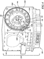
FIG. 4 is a drive-end view of the electrical generator illustrated inFIG. 1 according to an exemplary embodiment, showing the generator housing including an enclosure with an opening and a closure seated in the opening; -
FIG. 5 is perspective view of the closure of the electrical generator illustrated inFIG. 3 , showing a drive face of the closure; -
FIG. 6 is perspective view of the closure of the electrical generator illustrated inFIG. 3 , showing an anti-drive face of the closure; and -
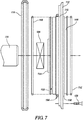
FIG. 7 is a side elevation view of the closure ofFIG. 3 , showing a bearing and sealing members exploded away from the closure. - Reference will now be made to the drawings wherein like reference numerals identify similar structural features or aspects of the subject disclosure. For purposes of explanation and illustration, and not limitation, a partial view of an exemplary embodiment of an electrical generator having a housing constructed in accordance with the present disclosure is shown
FIG. 1 and indicted generally withreference numeral 100. Other embodiments of accessory housings, electrical generators having such housings and mounting arrangements for gas turbine engine accessories in accordance with the disclosure, or aspects thereof, are provided inFigs. 2-7 , as will be described. The accessory housings described herein can be used for mounting accessories to gas turbine engines, such as variable speed constant frequency (VSCF) electrical generators to accessory gearboxes, though the present disclosure is not limited to VSCF electrical generators - Referring to
FIG. 1 , agas turbine engine 10 is shown.Gas turbine engine 10 includes acase 12 enclosing acompressor section 14, acombustion section 16, and aturbine section 18.Compressor section 14 ingests air from the ambient environment, compresses the air and provides the compressed air tocombustion section 16.Combustion section 16 generates a flow of high pressure combustion products, whichcombustion section 16 communicates toturbine section 18.Turbine section 18 expands the high pressure combustion products, extracts the work therefrom and communicates the high pressure combustion products to the ambient environment. Portions of the work are applied to each ofcompressor section 14, afan 20 operably associated withturbine section 18, and anelectrical generator 100 also operably associated withgas turbine engine 10. As shown and described hereingas turbine engine 10 has a single spool. This is for illustration purposes only and is non-limiting. As will be appreciated by those of skill in the art in view of the present disclosure, gas turbine engines having other architectures, e.g., two spool architectures, can also benefit from the present disclosure. -
Electrical generator 100 is operably associated withgas turbine engine 10 through a power take-off shaft 22. More specifically, electricallygenerator 100 is supported bygas turbine engine 10 at anaccessory gearbox 24 and is connected thereto via agear train 26 and power take-off shaft 22 toturbine section 18. A portion of the work communicated through power take-off shaft 22 andgear train 26 is applied as mechanical rotation R to arotor 102 ofelectrical generator 100, which is supported withinhousing 116 ofelectrical generator 100 by an anti-drive end bearing 104 and a drive end bearing 106. Theconnection rotor 102 togear train 26 can be, for example, via ashaft 128 that is fixed in rotation relative torotor 102 and arranged to communicate a portion of the work thereto as mechanical rotation R. In certain embodimentselectrical generator 100 can be a VSCF electrical generator such as those described inU.S. Patent Application Publication No. 2017/0365993 A1, filed June 15, 2016 . - With reference to
FIG. 2 ,mounting arrangement 108 is shown.Mounting arrangement 108 includes portions ofaccessory gearbox 24 andelectrical generator 100. In thisrespect accessory gearbox 24 includes anaccessory mount 28 having a v-band flange 30 extending a periphery ofaccessory mount 28.Electrical generator 100 includes ahousing 116 having anenclosure 118 and aclosure 110 with a v-band flange 112 extending about a periphery ofclosure 110. V-band flange 112 ofclosure 110 abuts v-band flange 30 ofaccessory mount 28 and is fixed thereto by a v-band 114, which compressively fixes closure 110 (andelectrical generator 100 therethrough) againstaccessory mount 28. It is contemplated that v-band 114 can be as described, for example, inU.S. Patent Application Publication No. 2009/0180827 A1 to Katcher, filed January 9, 2009 . - With reference to
FIG. 3 , portions of mountingarrangement 108 is shown. As shown inFIG. 3 closure 110 is fastened toenclosure 118 by one ormore fasteners 126,fastener 126 fixingclosure 110 toenclosure 118.Closure 110 is in turn fixed toaccessory mount 28 with v-band 114, which is compressively seated about both closure v-band flange 112 and mount v-band flange 30. Compressive seating of closure v-band flange 112 and mount v-band flange 30 causes load L1 (the weight of closure 110) and load L2 (load applied toclosure 110 by drive end bearing 106) to be communicated directly to mount 28 byclosure 110, bypassingenclosure 118 and limiting the stress withinenclosure 118. It is contemplated that load L3 ofenclosure 118 as well as load exerted by anti-drive end bearing 104 (shown inFIG. 1 ) be communicated to mount 28 indirectly, i.e., throughenclosure 118. - As will be appreciated by those of skill in the art, direct communication of load L through
closure 110 limits load carried byenclosure 118. This allowsenclosure 118 to be smaller and/or lighter than would otherwise be required. Incertain embodiments closure 110 is formed from aclosure material 120 having a greater mechanical strength than anenclosure material 122 formingenclosure 118, allowingclosure 110 to support a relatively large rotor with a correspondingly large enclosure - such as in certain VSCF electrical generator arrangements. For example,closure material 120 can have one or more of a yield strength, a tensile strength and/or a fatigue strength that is greater than that ofenclosure material 122. In this respect it is contemplated that, in certain embodiments,enclosure material 122 can be magnesium or a magnesium alloy andclosure material 120 can be an aluminum alloy, such as a 7075-family aluminum alloy. As will be appreciated by those of skill in the art in view of the present disclosure, 7075-family aluminum alloys have the advantage that strength can be dialed via surface finishing according load and/or vibration level exerted on closure 110 - for example by shot peening a machined surface ofclosure 110 to have a peened finish 124 (shown inFIG. 4 ) while retaining a common piece part housing, as required for an intended application. It is also contemplated that theclosure material 120 can include titanium, steel, or Inconel, as suitable for an intended application. - With reference to
FIG. 4 ,electrical generator 100 is shown according to an embodiment.Electrical generator 100 includeshousing 116, rotor 102 (shown inFIG. 1 ),fasteners 126, and v-band 114.Shaft 128 is fixed in rotation relative torotor 102, which is supported for rotation withinenclosure 118 withshaft 128 extending through ashaft aperture 130 defined byclosure 110.Fasteners 126 are arranged in a fastener pattern 132 (shown inFIG. 4 ) extending aboutshaft aperture 130 and fixclosure 110 toenclosure 118. Fastener pattern 132 (and fasteners 126) are located radially betweenshaft aperture 130 and v-band flange 112. In the illustrated exemplary embodiment fourteen (14)fasteners 126 are employed to fixclosure 110 toenclosure 118. This is for illustration purposes only and is non-limiting and it is to be understood and appreciated that embodiments ofelectrical generator 100 can have more that fourteen fasteners or fewer than fourteenfasteners fixing closure 110 toenclosure 118, as suitable for an intended application. -
Electrical generator 100 also has acoolant inlet tube 134, a low pressurecoolant outlet tube 136, a high pressurecoolant outlet tube 138, and ananti-rotation pin 140. Each ofcoolant inlet tube 134, low pressurecoolant outlet tube 136, high pressurecoolant outlet tube 138, andanti-rotation pin 140 are circumferentially distributed withinfastener pattern 132. In this respectcoolant inlet tube 134 is located between a circumferentiallyfirst fastener 126A and second circumferentiallyadjacent fastener 126B, and low pressurecoolant outlet tube 136 and high pressurecoolant outlet tube 138 are located between circumferentially adjacentsecond fastener 126B andthird fastener 126C. As will be appreciated by those of skill in the art in view of the present disclosure, this limits the number of fasteners require to retainclosure 110 toenclosure 118 because compressive engagement of tube keepers respectively seated withinclosure 110 and fixed toenclosure 118 also function to fixclosure 110 toenclosure 118.Anti-rotation pin 140 is similarly located between two circumferentially adjacent fasteners, i.e.,fastener 126D andfastener 126E, and fixesclosure 110 toenclosure 118 to further limit the number offasteners 126 required to fixclosure 110 toenclosure 118. - With reference to
FIG. 5 , adrive face 144 ofclosure 110 is shown.Closure 110 has a disk-like body with an anti-drive face 142 (shown inFIG. 6 ) and driveface 144. V-band flange 112 extends radially aboutanti-drive face 142 and driveface 144 at radially outermost location.Fastener pattern 132 is located radially between v-band flange 112 andshaft aperture 130, extends throughclosure 110 betweendrive face 144 andanti-drive face 142 for receiving fastener 126 (shown inFIG. 3 ), and has an axially extending faceannular portion 146. Faceannular portion 146 extends aboutshaft aperture 130 and in a direction oppositeanti-drive face 142 and has a mount sealingmember groove 148 defined therein. Mount sealingmember groove 148 extends aboutshaft aperture 130, is located on a radially outer surface 150 (shown inFIG. 7 ) of faceannular portion 146 and is a configured and adapted to seat therein a mount sealing member 152 (shown inFIG. 7 ) for sealingelectrical generator 100 against accessory mount 28 (shown inFIG. 1 ). - With reference to
FIG. 6 ,anti-drive face 142 ofclosure 110 is shown.Anti-drive face 142 has enclosureannular portion 154 and defines a bearing seat 156. Bearing seat 156 extends aboutshaft aperture 130 and extends axially therefrom, is arranged to seat therein drive end bearing 106 (shown inFIG. 1 ), and is located radially betweenshaft aperture 130 and enclosureannular portion 154. Enclosureannular portion 154 is located radially between bearing seat 156 and v-band flange 112, extends about bearingshaft aperture 130 and axially fromanti-drive face 142, and has an enclosure sealingmember groove 158 defined therein. Enclosure sealingmember groove 158 also extends aboutshaft aperture 130 and is configured and adapted to seat therein anenclosure sealing member 160 for sealingclosure 110 againstenclosure 118. Aninterior lubricant channel 162 extends radially between enclosureannular portion 154 and bearing seat 156 for providing a flow of lubricant therethrough to drive end bearing 106. - With reference to
FIG. 7 ,closure 110 is shown in an exploded view. Drive end bearing 106 seats in bearing seat 156 for rotatably supportingshaft 128, for example with bearing fasteners received throughclosure 110. Enclosure sealing member groove 158 seats in enclosure sealingmember groove 158 for sealingclosure 110 againstenclosure 118. Mount sealingmember 152 seats in mount sealingmember groove 148 for sealingclosure 110 againstaccessory mount 28. V-band 114 seats on v-band flange 112 for compressively engagingclosure 110 againstaccessory mount 28.Fasteners 126 are received through apertures of fastener pattern 132 (shown inFIG. 5 ) and fixclosure 110 toenclosure 118 such that load, e.g., one or more of loads L1-L3 (shown inFIG. 3 ), carried byclosure 110 is communicated directly to accessory mount 28 (shown inFIG. 1 ) throughclosure 110, and not throughenclosure 118, thereby allowing limiting load carried byenclosure 118 and associated stress withinenclosure 118. In the illustrated embodiment a secondclosure sealing member 164 is seated aboutclosure 112 to provide sealing ofenclosure 118. - The methods and systems of the present disclosure, as described above and shown in the drawings, provide for turbine engine accessories with superior properties including limited housing loads in accessories cantilevered from accessory gearbox mounts. While the apparatus and methods of the subject disclosure have been shown and described with reference to preferred embodiments, those skilled in the art will readily appreciate that changes and/or modifications may be made thereto without departing from the scope of the invention as defined by the claims.
Claims (11)
- A mounting arrangement (108) for a gas turbine engine accessory, comprising:an electrical generator comprising a housing, wherein the housing comprises:an enclosure (118) having a drive end with an opening; anda closure (110) seated in the opening and defining therethrough a shaft aperture (130), wherein the closure has a v-band flange (112) extending about a periphery of the closure (110) to limit load carried by the mounting arrangement when the engine accessory is mounted to an accessory gearbox mount in a cantilevered arrangement;the generator further comprising:a generator rotor (102) with a shaft (128) is supported for rotation within the enclosure (118), the shaft (128) extending through the shaft aperture (130) of the closure;a plurality of fasteners (126) arranged in a fastener pattern (132) extending about the shaft aperture (130) and fixing the closure (110) to the enclosure (118), the fastener pattern (132) located between the shaft aperture (130) and the v-band flange (112);wherein the mounting arrangement further comprises:an accessory gearbox with at least one accessory mount (28), the mount having a v-band flange (30) extending about the accessory mount (28), wherein the electrical generator is cantilevered from the accessory mount (28), wherein the v-band flange (112) of the closure abuts the v-band flange (30) of the accessory mount (28); anda v-band (114) extending about the v-band flange (30) of the accessory mount (28) and the v-band flange (112) of the closure, the v-band (114) compressively fixing the closure against the accessory mount (28).
- The mounting arrangement as recited in claim 1, wherein the enclosure is formed from a first material and the closure is formed from a second material, wherein the second material has greater mechanical strength than the first material.
- The mounting arrangement as recited in claim 2, wherein the mechanical strength includes at least one of yield strength, tensile strength, and fatigue strength.
- The mounting arrangement as recited in any preceding claim, wherein the enclosure is formed from magnesium or a magnesium alloy, and/or wherein the closure is formed from aluminum or a 7075-family aluminum alloy.
- The mounting arrangement as recited in any preceding claim, further comprising:an anti-rotation feature (140) arranged between two of the plurality of fasteners (126);a coolant inlet tube (134) arranged between two of the plurality of fasteners (126); andat least one coolant outlet tube (138) spaced apart from the coolant inlet tube (134) by one or more fastener (126).
- The mounting arrangement as recited in any preceding claim, further comprising a bearing (106) seated in the closure (110) and supporting the generator rotor (102) with the shaft (128) extending through the shaft aperture (130).
- The mounting arrangement as recited in the claim 5 or 6, wherein the generator shaft (128) carries windings for generating variable frequency electrical power according rotational speed of the shaft.
- The mounting arrangement as recited in claim 5, 6, or 7, wherein the closure (110) defines an interior lubricant channel (162) in fluid communication with the shaft aperture (130) and extending radially therefrom.
- The mounting arrangement as recited in any preceding claim, wherein the closure (110) has a mount annular portion (146) extending from a drive face (144) of the closure (110) and extending about the shaft aperture (130), wherein the drive annular portion has a mount sealing member groove (148) defined within a radially outer periphery of the mount annular portion, and further comprising a mount sealing member (152) seated in the mount sealing member groove (148) and extending about the shaft aperture (130).
- The mounting arrangement as recited in any preceding claim, wherein the closure (110) has an enclosure annular portion (154) extending from an anti-drive face (142) of the closure and extending about the shaft aperture (130), wherein the enclosure annular portion (154) has an enclosure sealing member groove (158) defined within a radially outer periphery of the enclosure annular portion (154), and further comprising an enclosure sealing member (160) seated in the enclosure sealing member groove (158) and extending about the shaft aperture.
- The mounting arrangement as recited in any preceding claim, wherein the generator is a variable speed constant frequency generator.
Applications Claiming Priority (1)
| Application Number | Priority Date | Filing Date | Title |
|---|---|---|---|
| US201862675974P | 2018-05-24 | 2018-05-24 |
Publications (2)
| Publication Number | Publication Date |
|---|---|
| EP3572643A1 EP3572643A1 (en) | 2019-11-27 |
| EP3572643B1 true EP3572643B1 (en) | 2021-06-30 |
Family
ID=66668720
Family Applications (1)
| Application Number | Title | Priority Date | Filing Date |
|---|---|---|---|
| EP19176460.4A Active EP3572643B1 (en) | 2018-05-24 | 2019-05-24 | Mounting arrangements for gas turbine engine accessories |
Country Status (3)
| Country | Link |
|---|---|
| US (1) | US11522412B2 (en) |
| EP (1) | EP3572643B1 (en) |
| KR (1) | KR102833269B1 (en) |
Families Citing this family (2)
| Publication number | Priority date | Publication date | Assignee | Title |
|---|---|---|---|---|
| FR3104542B1 (en) * | 2019-12-13 | 2021-12-03 | Safran Power Units | Auxiliary power unit comprising a direct-drive gas generator with an electric generator and an accessory box |
| CA3227937A1 (en) * | 2023-02-28 | 2025-04-25 | Pratt & Whitney Canada Corp. | Dynamic absorber for aircraft engine accessories |
Family Cites Families (17)
| Publication number | Priority date | Publication date | Assignee | Title |
|---|---|---|---|---|
| GB174526A (en) * | 1921-01-21 | 1922-02-02 | Gen Electric | Improvements in and relating to elastic fluid turbine driven sets |
| US2460502A (en) | 1946-07-18 | 1949-02-01 | Jack & Heintz Prec Ind Inc | Generator mounting flange |
| US2699343A (en) * | 1950-12-20 | 1955-01-11 | Bendix Aviat Corp | Quick disconnect mounting |
| US5178483A (en) * | 1991-11-26 | 1993-01-12 | Wang Wen Chang | Coupling device |
| US5267433A (en) | 1992-03-25 | 1993-12-07 | Allied-Signal, Inc. | Air turbine starter having a dual clutch |
| US6851267B2 (en) | 2002-12-18 | 2005-02-08 | Pratt & Whitney Canada Corp. | Compact quick attach starter-generator installation |
| DE102004022557B4 (en) * | 2004-05-07 | 2021-07-22 | Siemens Aktiengesellschaft | Electric machine with water cooling |
| US7059136B2 (en) * | 2004-08-27 | 2006-06-13 | General Electric Company | Air turbine powered accessory |
| US20070012129A1 (en) * | 2005-07-13 | 2007-01-18 | Honeywell International, Inc. | Adjustable flange arrangement for synchronization of multiple generators |
| US7550881B1 (en) * | 2006-01-17 | 2009-06-23 | Honeywell International Inc. | Vibration damper for generator or motor stator |
| EP2079152A3 (en) * | 2008-01-11 | 2011-04-13 | Goodrich Corporation | Mounting arrangement for an electrical generator |
| JP4876080B2 (en) | 2008-01-25 | 2012-02-15 | 富士重工業株式会社 | Environment recognition device |
| US9650964B2 (en) | 2010-12-28 | 2017-05-16 | General Electric Company | Accessory gearbox with a starter/generator |
| US9559569B2 (en) * | 2012-02-13 | 2017-01-31 | Ge Aviation Systems Llc | Arrangement for cooling an electric machine with a layer of thermally conducting and electrically insulating material |
| US10003186B2 (en) | 2016-06-15 | 2018-06-19 | Hamilton Sundstrand Corporation | Variable-speed constant-frequency power control |
| US10247296B2 (en) * | 2016-12-12 | 2019-04-02 | General Electric Company | Additively manufactured gearbox with integral heat exchanger |
| NL2019306B1 (en) * | 2017-07-20 | 2019-02-12 | E Traction Europe Bv | Cooling jacket and in-wheel motor with a cooling jacket |
-
2019
- 2019-01-11 US US16/245,790 patent/US11522412B2/en active Active
- 2019-05-24 KR KR1020190061009A patent/KR102833269B1/en active Active
- 2019-05-24 EP EP19176460.4A patent/EP3572643B1/en active Active
Also Published As
| Publication number | Publication date |
|---|---|
| KR20190134985A (en) | 2019-12-05 |
| US20190363610A1 (en) | 2019-11-28 |
| US11522412B2 (en) | 2022-12-06 |
| EP3572643A1 (en) | 2019-11-27 |
| KR102833269B1 (en) | 2025-07-11 |
Similar Documents
| Publication | Publication Date | Title |
|---|---|---|
| US8943840B2 (en) | Mounting assembly | |
| EP3258084B1 (en) | An accessory gearbox assembly and a gas turbine engine comprising an accessory gearbox assembly | |
| CN106168168B (en) | Accessory device and the method for assembling attachment and turbogenerator | |
| US20160017811A1 (en) | Gearbox mounting assembly | |
| CA3003005C (en) | Planetary gear system and air turbine starter | |
| EP3029358B1 (en) | Lightweight and compliant journal pin | |
| EP2696057A1 (en) | Aircraft engine | |
| EP2559883A2 (en) | Gas turbine engine accessory mount | |
| EP2518296A2 (en) | Fan drive gear system integrated carrier and torque frame | |
| JP2000179359A (en) | Variable rigidity locating link for gearbox | |
| WO2014105619A1 (en) | Multi-function boss for a turbine exhaust case | |
| EP3572643B1 (en) | Mounting arrangements for gas turbine engine accessories | |
| US11674449B2 (en) | Mount assembly for accessory gearbox of aircraft engine and associated method of assembly | |
| US20140245750A1 (en) | Circumferentially retained fairing | |
| EP2938865A2 (en) | Component retention with probe | |
| EP3094876A1 (en) | Bearing locking assemblies and methods of assembling the same | |
| US9352649B2 (en) | Accessory relay having an extended service life | |
| JP2008519580A (en) | Electromechanical equipment | |
| US9797397B2 (en) | Pump sleeve | |
| US11795881B2 (en) | Accessory box for a turbomachine | |
| US11365650B2 (en) | Mounting apparatus for a gas turbine engine | |
| US20200140107A1 (en) | Engine mounted aircraft gearbox disposed in pylon | |
| EP4424980A1 (en) | Dynamic absorber for aircraft engine accessories |
Legal Events
| Date | Code | Title | Description |
|---|---|---|---|
| PUAI | Public reference made under article 153(3) epc to a published international application that has entered the european phase |
Free format text: ORIGINAL CODE: 0009012 |
|
| STAA | Information on the status of an ep patent application or granted ep patent |
Free format text: STATUS: THE APPLICATION HAS BEEN PUBLISHED |
|
| AK | Designated contracting states |
Kind code of ref document: A1 Designated state(s): AL AT BE BG CH CY CZ DE DK EE ES FI FR GB GR HR HU IE IS IT LI LT LU LV MC MK MT NL NO PL PT RO RS SE SI SK SM TR |
|
| AX | Request for extension of the european patent |
Extension state: BA ME |
|
| STAA | Information on the status of an ep patent application or granted ep patent |
Free format text: STATUS: REQUEST FOR EXAMINATION WAS MADE |
|
| 17P | Request for examination filed |
Effective date: 20191202 |
|
| RBV | Designated contracting states (corrected) |
Designated state(s): AL AT BE BG CH CY CZ DE DK EE ES FI FR GB GR HR HU IE IS IT LI LT LU LV MC MK MT NL NO PL PT RO RS SE SI SK SM TR |
|
| GRAP | Despatch of communication of intention to grant a patent |
Free format text: ORIGINAL CODE: EPIDOSNIGR1 |
|
| STAA | Information on the status of an ep patent application or granted ep patent |
Free format text: STATUS: GRANT OF PATENT IS INTENDED |
|
| INTG | Intention to grant announced |
Effective date: 20210113 |
|
| GRAS | Grant fee paid |
Free format text: ORIGINAL CODE: EPIDOSNIGR3 |
|
| GRAA | (expected) grant |
Free format text: ORIGINAL CODE: 0009210 |
|
| STAA | Information on the status of an ep patent application or granted ep patent |
Free format text: STATUS: THE PATENT HAS BEEN GRANTED |
|
| AK | Designated contracting states |
Kind code of ref document: B1 Designated state(s): AL AT BE BG CH CY CZ DE DK EE ES FI FR GB GR HR HU IE IS IT LI LT LU LV MC MK MT NL NO PL PT RO RS SE SI SK SM TR |
|
| REG | Reference to a national code |
Ref country code: CH Ref legal event code: EP |
|
| REG | Reference to a national code |
Ref country code: AT Ref legal event code: REF Ref document number: 1406557 Country of ref document: AT Kind code of ref document: T Effective date: 20210715 |
|
| REG | Reference to a national code |
Ref country code: DE Ref legal event code: R096 Ref document number: 602019005691 Country of ref document: DE |
|
| REG | Reference to a national code |
Ref country code: IE Ref legal event code: FG4D |
|
| REG | Reference to a national code |
Ref country code: LT Ref legal event code: MG9D |
|
| PG25 | Lapsed in a contracting state [announced via postgrant information from national office to epo] |
Ref country code: HR Free format text: LAPSE BECAUSE OF FAILURE TO SUBMIT A TRANSLATION OF THE DESCRIPTION OR TO PAY THE FEE WITHIN THE PRESCRIBED TIME-LIMIT Effective date: 20210630 Ref country code: FI Free format text: LAPSE BECAUSE OF FAILURE TO SUBMIT A TRANSLATION OF THE DESCRIPTION OR TO PAY THE FEE WITHIN THE PRESCRIBED TIME-LIMIT Effective date: 20210630 Ref country code: BG Free format text: LAPSE BECAUSE OF FAILURE TO SUBMIT A TRANSLATION OF THE DESCRIPTION OR TO PAY THE FEE WITHIN THE PRESCRIBED TIME-LIMIT Effective date: 20210930 |
|
| REG | Reference to a national code |
Ref country code: NL Ref legal event code: MP Effective date: 20210630 |
|
| REG | Reference to a national code |
Ref country code: AT Ref legal event code: MK05 Ref document number: 1406557 Country of ref document: AT Kind code of ref document: T Effective date: 20210630 |
|
| PG25 | Lapsed in a contracting state [announced via postgrant information from national office to epo] |
Ref country code: GR Free format text: LAPSE BECAUSE OF FAILURE TO SUBMIT A TRANSLATION OF THE DESCRIPTION OR TO PAY THE FEE WITHIN THE PRESCRIBED TIME-LIMIT Effective date: 20211001 Ref country code: RS Free format text: LAPSE BECAUSE OF FAILURE TO SUBMIT A TRANSLATION OF THE DESCRIPTION OR TO PAY THE FEE WITHIN THE PRESCRIBED TIME-LIMIT Effective date: 20210630 Ref country code: SE Free format text: LAPSE BECAUSE OF FAILURE TO SUBMIT A TRANSLATION OF THE DESCRIPTION OR TO PAY THE FEE WITHIN THE PRESCRIBED TIME-LIMIT Effective date: 20210630 Ref country code: NO Free format text: LAPSE BECAUSE OF FAILURE TO SUBMIT A TRANSLATION OF THE DESCRIPTION OR TO PAY THE FEE WITHIN THE PRESCRIBED TIME-LIMIT Effective date: 20210930 Ref country code: LV Free format text: LAPSE BECAUSE OF FAILURE TO SUBMIT A TRANSLATION OF THE DESCRIPTION OR TO PAY THE FEE WITHIN THE PRESCRIBED TIME-LIMIT Effective date: 20210630 |
|
| PG25 | Lapsed in a contracting state [announced via postgrant information from national office to epo] |
Ref country code: SM Free format text: LAPSE BECAUSE OF FAILURE TO SUBMIT A TRANSLATION OF THE DESCRIPTION OR TO PAY THE FEE WITHIN THE PRESCRIBED TIME-LIMIT Effective date: 20210630 Ref country code: RO Free format text: LAPSE BECAUSE OF FAILURE TO SUBMIT A TRANSLATION OF THE DESCRIPTION OR TO PAY THE FEE WITHIN THE PRESCRIBED TIME-LIMIT Effective date: 20210630 Ref country code: PT Free format text: LAPSE BECAUSE OF FAILURE TO SUBMIT A TRANSLATION OF THE DESCRIPTION OR TO PAY THE FEE WITHIN THE PRESCRIBED TIME-LIMIT Effective date: 20211102 Ref country code: NL Free format text: LAPSE BECAUSE OF FAILURE TO SUBMIT A TRANSLATION OF THE DESCRIPTION OR TO PAY THE FEE WITHIN THE PRESCRIBED TIME-LIMIT Effective date: 20210630 Ref country code: CZ Free format text: LAPSE BECAUSE OF FAILURE TO SUBMIT A TRANSLATION OF THE DESCRIPTION OR TO PAY THE FEE WITHIN THE PRESCRIBED TIME-LIMIT Effective date: 20210630 Ref country code: AT Free format text: LAPSE BECAUSE OF FAILURE TO SUBMIT A TRANSLATION OF THE DESCRIPTION OR TO PAY THE FEE WITHIN THE PRESCRIBED TIME-LIMIT Effective date: 20210630 Ref country code: EE Free format text: LAPSE BECAUSE OF FAILURE TO SUBMIT A TRANSLATION OF THE DESCRIPTION OR TO PAY THE FEE WITHIN THE PRESCRIBED TIME-LIMIT Effective date: 20210630 Ref country code: ES Free format text: LAPSE BECAUSE OF FAILURE TO SUBMIT A TRANSLATION OF THE DESCRIPTION OR TO PAY THE FEE WITHIN THE PRESCRIBED TIME-LIMIT Effective date: 20210630 Ref country code: SK Free format text: LAPSE BECAUSE OF FAILURE TO SUBMIT A TRANSLATION OF THE DESCRIPTION OR TO PAY THE FEE WITHIN THE PRESCRIBED TIME-LIMIT Effective date: 20210630 |
|
| PG25 | Lapsed in a contracting state [announced via postgrant information from national office to epo] |
Ref country code: PL Free format text: LAPSE BECAUSE OF FAILURE TO SUBMIT A TRANSLATION OF THE DESCRIPTION OR TO PAY THE FEE WITHIN THE PRESCRIBED TIME-LIMIT Effective date: 20210630 |
|
| REG | Reference to a national code |
Ref country code: DE Ref legal event code: R097 Ref document number: 602019005691 Country of ref document: DE |
|
| PG25 | Lapsed in a contracting state [announced via postgrant information from national office to epo] |
Ref country code: DK Free format text: LAPSE BECAUSE OF FAILURE TO SUBMIT A TRANSLATION OF THE DESCRIPTION OR TO PAY THE FEE WITHIN THE PRESCRIBED TIME-LIMIT Effective date: 20210630 |
|
| PLBE | No opposition filed within time limit |
Free format text: ORIGINAL CODE: 0009261 |
|
| STAA | Information on the status of an ep patent application or granted ep patent |
Free format text: STATUS: NO OPPOSITION FILED WITHIN TIME LIMIT |
|
| PG25 | Lapsed in a contracting state [announced via postgrant information from national office to epo] |
Ref country code: AL Free format text: LAPSE BECAUSE OF FAILURE TO SUBMIT A TRANSLATION OF THE DESCRIPTION OR TO PAY THE FEE WITHIN THE PRESCRIBED TIME-LIMIT Effective date: 20210630 |
|
| 26N | No opposition filed |
Effective date: 20220331 |
|
| PG25 | Lapsed in a contracting state [announced via postgrant information from national office to epo] |
Ref country code: IT Free format text: LAPSE BECAUSE OF FAILURE TO SUBMIT A TRANSLATION OF THE DESCRIPTION OR TO PAY THE FEE WITHIN THE PRESCRIBED TIME-LIMIT Effective date: 20210630 |
|
| REG | Reference to a national code |
Ref country code: CH Ref legal event code: PL |
|
| REG | Reference to a national code |
Ref country code: BE Ref legal event code: MM Effective date: 20220531 |
|
| PG25 | Lapsed in a contracting state [announced via postgrant information from national office to epo] |
Ref country code: MC Free format text: LAPSE BECAUSE OF FAILURE TO SUBMIT A TRANSLATION OF THE DESCRIPTION OR TO PAY THE FEE WITHIN THE PRESCRIBED TIME-LIMIT Effective date: 20210630 Ref country code: LU Free format text: LAPSE BECAUSE OF NON-PAYMENT OF DUE FEES Effective date: 20220524 Ref country code: LI Free format text: LAPSE BECAUSE OF NON-PAYMENT OF DUE FEES Effective date: 20220531 Ref country code: CH Free format text: LAPSE BECAUSE OF NON-PAYMENT OF DUE FEES Effective date: 20220531 |
|
| PG25 | Lapsed in a contracting state [announced via postgrant information from national office to epo] |
Ref country code: LT Free format text: LAPSE BECAUSE OF FAILURE TO SUBMIT A TRANSLATION OF THE DESCRIPTION OR TO PAY THE FEE WITHIN THE PRESCRIBED TIME-LIMIT Effective date: 20210630 Ref country code: IE Free format text: LAPSE BECAUSE OF NON-PAYMENT OF DUE FEES Effective date: 20220524 |
|
| PG25 | Lapsed in a contracting state [announced via postgrant information from national office to epo] |
Ref country code: BE Free format text: LAPSE BECAUSE OF NON-PAYMENT OF DUE FEES Effective date: 20220531 |
|
| P01 | Opt-out of the competence of the unified patent court (upc) registered |
Effective date: 20230522 |
|
| PG25 | Lapsed in a contracting state [announced via postgrant information from national office to epo] |
Ref country code: HU Free format text: LAPSE BECAUSE OF FAILURE TO SUBMIT A TRANSLATION OF THE DESCRIPTION OR TO PAY THE FEE WITHIN THE PRESCRIBED TIME-LIMIT; INVALID AB INITIO Effective date: 20190524 |
|
| PG25 | Lapsed in a contracting state [announced via postgrant information from national office to epo] |
Ref country code: MK Free format text: LAPSE BECAUSE OF FAILURE TO SUBMIT A TRANSLATION OF THE DESCRIPTION OR TO PAY THE FEE WITHIN THE PRESCRIBED TIME-LIMIT Effective date: 20210630 Ref country code: CY Free format text: LAPSE BECAUSE OF FAILURE TO SUBMIT A TRANSLATION OF THE DESCRIPTION OR TO PAY THE FEE WITHIN THE PRESCRIBED TIME-LIMIT Effective date: 20210630 |
|
| PG25 | Lapsed in a contracting state [announced via postgrant information from national office to epo] |
Ref country code: MT Free format text: LAPSE BECAUSE OF FAILURE TO SUBMIT A TRANSLATION OF THE DESCRIPTION OR TO PAY THE FEE WITHIN THE PRESCRIBED TIME-LIMIT Effective date: 20210630 |
|
| PGFP | Annual fee paid to national office [announced via postgrant information from national office to epo] |
Ref country code: DE Payment date: 20250423 Year of fee payment: 7 |
|
| PGFP | Annual fee paid to national office [announced via postgrant information from national office to epo] |
Ref country code: GB Payment date: 20250423 Year of fee payment: 7 |
|
| PGFP | Annual fee paid to national office [announced via postgrant information from national office to epo] |
Ref country code: FR Payment date: 20250423 Year of fee payment: 7 |
|
| PG25 | Lapsed in a contracting state [announced via postgrant information from national office to epo] |
Ref country code: TR Free format text: LAPSE BECAUSE OF FAILURE TO SUBMIT A TRANSLATION OF THE DESCRIPTION OR TO PAY THE FEE WITHIN THE PRESCRIBED TIME-LIMIT Effective date: 20210630 |