EP3572269A1 - System and method for supplying electric energy to a mining vehicle and a mining vehicle - Google Patents
System and method for supplying electric energy to a mining vehicle and a mining vehicle Download PDFInfo
- Publication number
- EP3572269A1 EP3572269A1 EP18173724.8A EP18173724A EP3572269A1 EP 3572269 A1 EP3572269 A1 EP 3572269A1 EP 18173724 A EP18173724 A EP 18173724A EP 3572269 A1 EP3572269 A1 EP 3572269A1
- Authority
- EP
- European Patent Office
- Prior art keywords
- mining vehicle
- energy unit
- bipolar
- lvdc
- batteries
- Prior art date
- Legal status (The legal status is an assumption and is not a legal conclusion. Google has not performed a legal analysis and makes no representation as to the accuracy of the status listed.)
- Granted
Links
Images

Classifications
-
- H—ELECTRICITY
- H02—GENERATION; CONVERSION OR DISTRIBUTION OF ELECTRIC POWER
- H02J—ELECTRIC POWER NETWORKS; CIRCUIT ARRANGEMENTS OR SYSTEMS FOR SUPPLYING OR DISTRIBUTING ELECTRIC POWER; SYSTEMS FOR STORING ELECTRIC ENERGY
- H02J1/00—Circuit arrangements for DC mains or DC distribution networks
- H02J1/08—Three-wire DC power distribution systems; Systems having more than three wires
-
- B—PERFORMING OPERATIONS; TRANSPORTING
- B60—VEHICLES IN GENERAL
- B60L—PROPULSION OF ELECTRICALLY-PROPELLED VEHICLES; SUPPLYING ELECTRIC POWER FOR AUXILIARY EQUIPMENT OF ELECTRICALLY-PROPELLED VEHICLES; ELECTRODYNAMIC BRAKE SYSTEMS FOR VEHICLES IN GENERAL; MAGNETIC SUSPENSION OR LEVITATION FOR VEHICLES; MONITORING OPERATING VARIABLES OF ELECTRICALLY-PROPELLED VEHICLES; ELECTRIC SAFETY DEVICES FOR ELECTRICALLY-PROPELLED VEHICLES
- B60L50/00—Electric propulsion with power supplied within the vehicle
- B60L50/50—Electric propulsion with power supplied within the vehicle using propulsion power supplied by batteries or fuel cells
- B60L50/53—Electric propulsion with power supplied within the vehicle using propulsion power supplied by batteries or fuel cells in combination with an external power supply, e.g. from overhead contact lines
-
- B—PERFORMING OPERATIONS; TRANSPORTING
- B60—VEHICLES IN GENERAL
- B60L—PROPULSION OF ELECTRICALLY-PROPELLED VEHICLES; SUPPLYING ELECTRIC POWER FOR AUXILIARY EQUIPMENT OF ELECTRICALLY-PROPELLED VEHICLES; ELECTRODYNAMIC BRAKE SYSTEMS FOR VEHICLES IN GENERAL; MAGNETIC SUSPENSION OR LEVITATION FOR VEHICLES; MONITORING OPERATING VARIABLES OF ELECTRICALLY-PROPELLED VEHICLES; ELECTRIC SAFETY DEVICES FOR ELECTRICALLY-PROPELLED VEHICLES
- B60L50/00—Electric propulsion with power supplied within the vehicle
- B60L50/50—Electric propulsion with power supplied within the vehicle using propulsion power supplied by batteries or fuel cells
- B60L50/60—Electric propulsion with power supplied within the vehicle using propulsion power supplied by batteries or fuel cells using power supplied by batteries
-
- B—PERFORMING OPERATIONS; TRANSPORTING
- B60—VEHICLES IN GENERAL
- B60L—PROPULSION OF ELECTRICALLY-PROPELLED VEHICLES; SUPPLYING ELECTRIC POWER FOR AUXILIARY EQUIPMENT OF ELECTRICALLY-PROPELLED VEHICLES; ELECTRODYNAMIC BRAKE SYSTEMS FOR VEHICLES IN GENERAL; MAGNETIC SUSPENSION OR LEVITATION FOR VEHICLES; MONITORING OPERATING VARIABLES OF ELECTRICALLY-PROPELLED VEHICLES; ELECTRIC SAFETY DEVICES FOR ELECTRICALLY-PROPELLED VEHICLES
- B60L53/00—Methods of charging batteries, specially adapted for electric vehicles; Charging stations or on-board charging equipment therefor; Exchange of energy storage elements in electric vehicles
- B60L53/10—Methods of charging batteries, specially adapted for electric vehicles; Charging stations or on-board charging equipment therefor; Exchange of energy storage elements in electric vehicles characterised by the energy transfer between the charging station and the vehicle
- B60L53/14—Conductive energy transfer
-
- B—PERFORMING OPERATIONS; TRANSPORTING
- B60—VEHICLES IN GENERAL
- B60L—PROPULSION OF ELECTRICALLY-PROPELLED VEHICLES; SUPPLYING ELECTRIC POWER FOR AUXILIARY EQUIPMENT OF ELECTRICALLY-PROPELLED VEHICLES; ELECTRODYNAMIC BRAKE SYSTEMS FOR VEHICLES IN GENERAL; MAGNETIC SUSPENSION OR LEVITATION FOR VEHICLES; MONITORING OPERATING VARIABLES OF ELECTRICALLY-PROPELLED VEHICLES; ELECTRIC SAFETY DEVICES FOR ELECTRICALLY-PROPELLED VEHICLES
- B60L53/00—Methods of charging batteries, specially adapted for electric vehicles; Charging stations or on-board charging equipment therefor; Exchange of energy storage elements in electric vehicles
- B60L53/20—Methods of charging batteries, specially adapted for electric vehicles; Charging stations or on-board charging equipment therefor; Exchange of energy storage elements in electric vehicles characterised by converters located in the vehicle
-
- B—PERFORMING OPERATIONS; TRANSPORTING
- B60—VEHICLES IN GENERAL
- B60L—PROPULSION OF ELECTRICALLY-PROPELLED VEHICLES; SUPPLYING ELECTRIC POWER FOR AUXILIARY EQUIPMENT OF ELECTRICALLY-PROPELLED VEHICLES; ELECTRODYNAMIC BRAKE SYSTEMS FOR VEHICLES IN GENERAL; MAGNETIC SUSPENSION OR LEVITATION FOR VEHICLES; MONITORING OPERATING VARIABLES OF ELECTRICALLY-PROPELLED VEHICLES; ELECTRIC SAFETY DEVICES FOR ELECTRICALLY-PROPELLED VEHICLES
- B60L58/00—Methods or circuit arrangements for monitoring or controlling batteries or fuel cells, specially adapted for electric vehicles
- B60L58/10—Methods or circuit arrangements for monitoring or controlling batteries or fuel cells, specially adapted for electric vehicles for monitoring or controlling batteries
- B60L58/18—Methods or circuit arrangements for monitoring or controlling batteries or fuel cells, specially adapted for electric vehicles for monitoring or controlling batteries of two or more battery modules
- B60L58/19—Switching between serial connection and parallel connection of battery modules
-
- B—PERFORMING OPERATIONS; TRANSPORTING
- B60—VEHICLES IN GENERAL
- B60L—PROPULSION OF ELECTRICALLY-PROPELLED VEHICLES; SUPPLYING ELECTRIC POWER FOR AUXILIARY EQUIPMENT OF ELECTRICALLY-PROPELLED VEHICLES; ELECTRODYNAMIC BRAKE SYSTEMS FOR VEHICLES IN GENERAL; MAGNETIC SUSPENSION OR LEVITATION FOR VEHICLES; MONITORING OPERATING VARIABLES OF ELECTRICALLY-PROPELLED VEHICLES; ELECTRIC SAFETY DEVICES FOR ELECTRICALLY-PROPELLED VEHICLES
- B60L58/00—Methods or circuit arrangements for monitoring or controlling batteries or fuel cells, specially adapted for electric vehicles
- B60L58/10—Methods or circuit arrangements for monitoring or controlling batteries or fuel cells, specially adapted for electric vehicles for monitoring or controlling batteries
- B60L58/18—Methods or circuit arrangements for monitoring or controlling batteries or fuel cells, specially adapted for electric vehicles for monitoring or controlling batteries of two or more battery modules
- B60L58/22—Balancing the charge of battery modules
-
- H—ELECTRICITY
- H02—GENERATION; CONVERSION OR DISTRIBUTION OF ELECTRIC POWER
- H02J—ELECTRIC POWER NETWORKS; CIRCUIT ARRANGEMENTS OR SYSTEMS FOR SUPPLYING OR DISTRIBUTING ELECTRIC POWER; SYSTEMS FOR STORING ELECTRIC ENERGY
- H02J7/00—Circuit arrangements for charging or discharging batteries or for supplying loads from batteries
- H02J7/50—Circuit arrangements for charging or discharging batteries or for supplying loads from batteries acting upon multiple batteries simultaneously or sequentially
- H02J7/575—Parallel/serial switching of connection of batteries to charge or load circuit
-
- B—PERFORMING OPERATIONS; TRANSPORTING
- B60—VEHICLES IN GENERAL
- B60L—PROPULSION OF ELECTRICALLY-PROPELLED VEHICLES; SUPPLYING ELECTRIC POWER FOR AUXILIARY EQUIPMENT OF ELECTRICALLY-PROPELLED VEHICLES; ELECTRODYNAMIC BRAKE SYSTEMS FOR VEHICLES IN GENERAL; MAGNETIC SUSPENSION OR LEVITATION FOR VEHICLES; MONITORING OPERATING VARIABLES OF ELECTRICALLY-PROPELLED VEHICLES; ELECTRIC SAFETY DEVICES FOR ELECTRICALLY-PROPELLED VEHICLES
- B60L2200/00—Type of vehicles
- B60L2200/40—Working vehicles
-
- H—ELECTRICITY
- H02—GENERATION; CONVERSION OR DISTRIBUTION OF ELECTRIC POWER
- H02J—ELECTRIC POWER NETWORKS; CIRCUIT ARRANGEMENTS OR SYSTEMS FOR SUPPLYING OR DISTRIBUTING ELECTRIC POWER; SYSTEMS FOR STORING ELECTRIC ENERGY
- H02J2105/00—Networks for supplying or distributing electric power characterised by their spatial reach or by the load
- H02J2105/30—Networks for supplying or distributing electric power characterised by their spatial reach or by the load the load networks being external to vehicles, i.e. exchanging power with vehicles
- H02J2105/33—Networks for supplying or distributing electric power characterised by their spatial reach or by the load the load networks being external to vehicles, i.e. exchanging power with vehicles exchanging power with road vehicles
- H02J2105/37—Networks for supplying or distributing electric power characterised by their spatial reach or by the load the load networks being external to vehicles, i.e. exchanging power with vehicles exchanging power with road vehicles exchanging power with electric vehicles [EV] or with hybrid electric vehicles [HEV]
-
- Y—GENERAL TAGGING OF NEW TECHNOLOGICAL DEVELOPMENTS; GENERAL TAGGING OF CROSS-SECTIONAL TECHNOLOGIES SPANNING OVER SEVERAL SECTIONS OF THE IPC; TECHNICAL SUBJECTS COVERED BY FORMER USPC CROSS-REFERENCE ART COLLECTIONS [XRACs] AND DIGESTS
- Y02—TECHNOLOGIES OR APPLICATIONS FOR MITIGATION OR ADAPTATION AGAINST CLIMATE CHANGE
- Y02P—CLIMATE CHANGE MITIGATION TECHNOLOGIES IN THE PRODUCTION OR PROCESSING OF GOODS
- Y02P90/00—Enabling technologies with a potential contribution to greenhouse gas [GHG] emissions mitigation
- Y02P90/60—Electric or hybrid propulsion means for production processes
-
- Y—GENERAL TAGGING OF NEW TECHNOLOGICAL DEVELOPMENTS; GENERAL TAGGING OF CROSS-SECTIONAL TECHNOLOGIES SPANNING OVER SEVERAL SECTIONS OF THE IPC; TECHNICAL SUBJECTS COVERED BY FORMER USPC CROSS-REFERENCE ART COLLECTIONS [XRACs] AND DIGESTS
- Y02—TECHNOLOGIES OR APPLICATIONS FOR MITIGATION OR ADAPTATION AGAINST CLIMATE CHANGE
- Y02T—CLIMATE CHANGE MITIGATION TECHNOLOGIES RELATED TO TRANSPORTATION
- Y02T10/00—Road transport of goods or passengers
- Y02T10/60—Other road transportation technologies with climate change mitigation effect
- Y02T10/70—Energy storage systems for electromobility, e.g. batteries
-
- Y—GENERAL TAGGING OF NEW TECHNOLOGICAL DEVELOPMENTS; GENERAL TAGGING OF CROSS-SECTIONAL TECHNOLOGIES SPANNING OVER SEVERAL SECTIONS OF THE IPC; TECHNICAL SUBJECTS COVERED BY FORMER USPC CROSS-REFERENCE ART COLLECTIONS [XRACs] AND DIGESTS
- Y02—TECHNOLOGIES OR APPLICATIONS FOR MITIGATION OR ADAPTATION AGAINST CLIMATE CHANGE
- Y02T—CLIMATE CHANGE MITIGATION TECHNOLOGIES RELATED TO TRANSPORTATION
- Y02T10/00—Road transport of goods or passengers
- Y02T10/60—Other road transportation technologies with climate change mitigation effect
- Y02T10/7072—Electromobility specific charging systems or methods for batteries, ultracapacitors, supercapacitors or double-layer capacitors
-
- Y—GENERAL TAGGING OF NEW TECHNOLOGICAL DEVELOPMENTS; GENERAL TAGGING OF CROSS-SECTIONAL TECHNOLOGIES SPANNING OVER SEVERAL SECTIONS OF THE IPC; TECHNICAL SUBJECTS COVERED BY FORMER USPC CROSS-REFERENCE ART COLLECTIONS [XRACs] AND DIGESTS
- Y02—TECHNOLOGIES OR APPLICATIONS FOR MITIGATION OR ADAPTATION AGAINST CLIMATE CHANGE
- Y02T—CLIMATE CHANGE MITIGATION TECHNOLOGIES RELATED TO TRANSPORTATION
- Y02T90/00—Enabling technologies or technologies with a potential or indirect contribution to GHG emissions mitigation
- Y02T90/10—Technologies relating to charging of electric vehicles
- Y02T90/14—Plug-in electric vehicles
Definitions
- the invention relates to a system and method for supplying electric energy to a mining vehicle and a mining vehicle.
- Underground mining vehicles require high power during their use. If electric energy is used for supplying the mining vehicles, the voltage level of the components should not be very high because high voltage level requires large clearances and insulations, for example. This leads to large, complicated, and expensive components. Typically, the mining vehicles should, however, be as compact as possible. On the other hand, lower voltage level causes that the currents in the system rise. High current requires thick conductors, for example, in the supply system and in the mining vehicle thereby raising the costs.
- An object of the invention is to provide a new system, method and a mining vehicle.
- the invention is characterized by what is stated in the independent claims. Some embodiments of the invention are disclosed in the dependent claims.
- electric energy is supplied to a mining vehicle using a system comprising a bipolar LVDC supply having a certain total voltage.
- the mining vehicle comprises at least a first energy unit and a second energy unit.
- the first energy unit is connected to a part of said certain total voltage and the second energy unit is connected to another part of said certain total voltage.
- bipolar LVDC supply supplies power on the total voltage to the mining vehicle whereby the supplied power may be high although the current is moderate.
- the bipolar LVDC supply comprises a positive pole and a negative pole and a neutral point between the positive pole and the negative pole.
- the first energy unit may be connected between the positive pole and the neutral point and the second energy unit may be connected between the negative pole and the neutral point.
- the bipolar LVDC supply comprises a first converter and a second converter connected in series.
- the converters may be used for keeping the voltage balanced in both halves of the mining vehicle. It is possible to arrange the neutral point between the first and second converters.
- the first energy unit and the second energy unit comprise traction motors of the mining vehicle.
- the first energy unit and the second energy unit comprise batteries and the mining vehicle comprises connecting means and a control unit.
- the control unit may be arranged to connect the batteries in parallel in drive mode and arranged to connect the batteries in series in charge mode. In drive mode the connect in parallel means that the voltage level required for the vehicle DC-bus and the components in the vehicle is rather low. In charge mode a higher charging voltage is supplied. This allows for a use of a simple and cheap plug-socket connection and smaller and lighter cables for high power fast charging.
- Figure 1 shows a schematic of an electric system of a mining vehicle.
- the mining vehicle may be a dump truck, a LHD (load-haul-dump vehicle), an underground mining truck or a drill rig, for example.
- LHD load-haul-dump vehicle
- underground mining truck or a drill rig, for example.
- Reference numeral 1 depicts a bipolar LVDC (low voltage direct current) supply.
- the total voltage of the bipolar LVDC supply is 1500 V.
- the total voltage may be lower or higher than that, such as 400 V, 800 V, 1000 V or 5 kV.
- a voltage level of 1500 V or less is advantageous because such voltage level is still considered as low voltage according to the IEC rules and the European Union directive 2014/35/EU i.e. low voltage directive, for example. Higher voltage would result in requirements with larger clearances etc. leading to larger, complicated and expensive components.
- the mining vehicle comprises connectors 2a and 2b for connecting the mining vehicle to the bipolar LVDC supply 1.
- the connectors 2a and 2b may be trolley connections connecting the mining vehicle to a trolley line, for example.
- the connectors 2a and 2b may be a charging connector/coupler of a charging device, for example.
- the connectors 2a and 2b may be separate connectors or connected to the same charging connector/coupler.
- Reference numerals 3a, 3b and 3c depict the DC bus of the mining vehicle.
- 3a is the positive pole bus bar
- 3b is the negative pole bus bar
- 3c is the neutral or 0V bus bar.
- the total voltage of the bipolar LVDC supply is divided in to two halves that are substantially equal. Thus, if the total voltage of the bipolar LVDC supply is 1500 V, for example, in the mining vehicle the total voltage is separated to two halves to comprise +750 V, 0 V and -750 V levels.
- the mining vehicle comprises a first traction battery 4a and a second traction battery 4b.
- the traction batteries 4a and 4b may be used as a power source when the mining vehicle is used without a contact to the outside power supply, thus, outside of a trolley line, for example.
- DC/DC converters 5a, 5b may be used for connecting the traction batteries 4a, 4b to the DC bus of the mining vehicle.
- the first traction battery 4a is connected to a first part of the total voltage and the second traction battery 4b is connected to another part of the total voltage.
- the DC/DC converters 5a, 5b are not necessary for connecting the traction batteries 4a, 4b to the DC bus of the mining vehicle. This is the case when an external charger is used providing that the charger itself controls its voltage, for example.
- the mining vehicle further comprises a first traction motor 6a and a second traction motor 6b.
- the mining vehicle may comprise two separate traction motor drives, that is one traction motor drive per axle.
- the two traction motor drives may also be connected together into a summation gear.
- the first traction motor 6a is connected to the first part of the total voltage and the second traction motor 6b is connected to the another part of the total voltage.
- the traction motors 6a and 6b are connected to the DC bus of the mining vehicle with inverters 7a and 7b.
- the mining vehicle may comprise a plurality of wheel hub motors, that is a plurality of traction motors.
- Each wheel may comprise a wheel hub motor.
- a four-wheel mining vehicle comprises four wheel hub motors or traction motors, for example. If the mining vehicle comprises more than four wheels, the mining vehicle may also comprise more than four wheel hub motors.
- the mining vehicle may also comprise odd number of wheel hub motors.
- the first energy unit connected to a part of said certain total voltage of the bipolar LVDC supply may comprise one or more traction motors such as wheel hub motors and the second energy unit connected to another part of said certain total voltage of the bipolar LVDC supply may comprise one or more traction motors such as wheel hub motors.
- the mining vehicle further comprises a first brake resistor 8a and a second brake resistor 8b.
- the brake resistors 8a and 8b may be connected to the DC side of the inverters 7a and 7b.
- the brake resistors 8a and 8b may be switched to each DC bus halves to maintain the voltage symmetry.
- the brake resistors 8a and 8b may be used for maintaining the voltage symmetry during downhill drive, especially.
- FIG. 2 shows a schematic how to connect the batteries of the mining vehicle.
- the electric system of the mining vehicle may comprise two or more even numbered amount of batteries. In drive mode of the mining vehicle, the batteries are connected in parallel. In charge mode of the mining vehicle, the batteries are connected in series.
- the contactors K1, K2, K4, K5, K6, K7 and K8 are connecting means that are used for providing the connecting in parallel and the connecting in series.
- Contactor K1 is a positive pole charging contactor and contactor K2 is a negative pole charging contactor.
- Contactors K4 and K6 are used for positive pole disconnection for charging busbars.
- Contactors K5 and K7 are used for negative pole disconnection for charging busbars.
- Contactor K8 is a neutral pole connection device for charging busbars.
- the control unit 9 controls the contactors.
- the battery energy for use is taken from the drive mode output 9 depicted in the Figure 2 .
- contactors K4, K5, K6, and K7 are opened (break contact), after which the contactor K8 is closed (make contact).
- the contactors K1 and K2 are closed (make contact).
- the bipolar charging of the batteries does not necessarily require a neutral point connection from the charging system because the batteries are normally parallel-connected and share the same SOC and voltage.
- the neutral point N is at 0V inherently.
- Figure 3 shows a solution similar to shown in Figure 1 but with an improvement relating to voltage balance.
- the mining vehicle comprises a neutral point connector 2c.
- the neutral point connector 2c connects the centreline or 0 V or neutral point of the bipolar LVDC supply 1 to the mining vehicle.
- the improved voltage balance using the neutral point in the LVDC supply is advantageous especially if the mining vehicle comprises odd number of traction motors, for example. Further balancing may be performed using the brake resistors 8a, 8b and/or DC/DC converters 5a, 5b.
- the bipolar LVDC supply 1 is supplied from an electric grid 11.
- the bipolar LVDC supply 1 may comprise a transformer 12.
- the transformer 12 comprises two secondaries 12a, 12b. According to an embodiment the number of secondaries of the transformer 12 is one. According to another embodiment the number of the secondaries of the transformer 12 is more than two.
- the bipolar LVDC supply 1 further comprises a first converter 13a and a second converter 13b.
- the first converter 13a and the second converter 13b are connected in series whereby the neutral point is arranged between the first and second converters. Thereby the centerline of the mining vehicle is effectively balanced and thus the voltage balance is maintained on a high level.
- the bipolar LVDC supply with the neutral point may also be provided using one converter.
- the converter may be a three level NPC (Neutral-Point-Clamped) inverter, for example.
- Figure 4 shows a solution where the improvement relating to voltage balance is implemented in a manner similar to the solution in Figure 3 .
- the mining vehicle comprises a neutral pole charging contactor K3.
- the mining vehicle may comprise a three level NPC inverter or any other multi level inverter for driving a motor having a higher voltage level.
- a motor may be connected between the positive pole and the negative pole and possibly to the neutral pole, also.
- an energy unit may be connected between the positive pole and the negative pole with neutral connection using a three level NPC inverter, for example. If such an energy unit is bipolar as such and comprises a neutral point or it comprises components connected in series over which the voltage divides naturally, the components of the energy unit need to tolerate a lower voltage, only.
- the energy unit connected to a part of said certain total voltage may comprise a traction motor and/or a battery and/or any other electrical component.
Landscapes
- Engineering & Computer Science (AREA)
- Power Engineering (AREA)
- Transportation (AREA)
- Mechanical Engineering (AREA)
- Life Sciences & Earth Sciences (AREA)
- Sustainable Development (AREA)
- Sustainable Energy (AREA)
- Electric Propulsion And Braking For Vehicles (AREA)
- Charge And Discharge Circuits For Batteries Or The Like (AREA)
Abstract
Description
- The invention relates to a system and method for supplying electric energy to a mining vehicle and a mining vehicle.
- Underground mining vehicles require high power during their use. If electric energy is used for supplying the mining vehicles, the voltage level of the components should not be very high because high voltage level requires large clearances and insulations, for example. This leads to large, complicated, and expensive components. Typically, the mining vehicles should, however, be as compact as possible. On the other hand, lower voltage level causes that the currents in the system rise. High current requires thick conductors, for example, in the supply system and in the mining vehicle thereby raising the costs.
- An object of the invention is to provide a new system, method and a mining vehicle. The invention is characterized by what is stated in the independent claims. Some embodiments of the invention are disclosed in the dependent claims.
- In the presented solution electric energy is supplied to a mining vehicle using a system comprising a bipolar LVDC supply having a certain total voltage. The mining vehicle comprises at least a first energy unit and a second energy unit. The first energy unit is connected to a part of said certain total voltage and the second energy unit is connected to another part of said certain total voltage. Thereby the components of the first and second energy unit need to tolerate a voltage level that is only a part of the total voltage. However, bipolar LVDC supply supplies power on the total voltage to the mining vehicle whereby the supplied power may be high although the current is moderate.
- According to an embodiment, the bipolar LVDC supply comprises a positive pole and a negative pole and a neutral point between the positive pole and the negative pole. The first energy unit may be connected between the positive pole and the neutral point and the second energy unit may be connected between the negative pole and the neutral point. Thereby the voltage balance is reliable in the mining vehicle.
- According to another embodiment, the bipolar LVDC supply comprises a first converter and a second converter connected in series. The converters may be used for keeping the voltage balanced in both halves of the mining vehicle. It is possible to arrange the neutral point between the first and second converters.
- According to another embodiment, the first energy unit and the second energy unit comprise traction motors of the mining vehicle.
- According to another embodiment, the first energy unit and the second energy unit comprise batteries and the mining vehicle comprises connecting means and a control unit. The control unit may be arranged to connect the batteries in parallel in drive mode and arranged to connect the batteries in series in charge mode. In drive mode the connect in parallel means that the voltage level required for the vehicle DC-bus and the components in the vehicle is rather low. In charge mode a higher charging voltage is supplied. This allows for a use of a simple and cheap plug-socket connection and smaller and lighter cables for high power fast charging.
- In the following the invention will be described in greater detail by means of embodiments with reference to the attached drawings, in which
-
Figure 1 is a schematic of an electric system of a mining vehicle; -
Figure 2 is a schematic showing how to connect the batteries of the mining vehicle; -
Figure 3 is a schematic of another electric system of a mining vehicle; and -
Figure 4 is a schematic of another embodiment how to connect the batteries of the mining vehicle. -
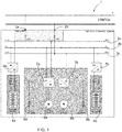
Figure 1 shows a schematic of an electric system of a mining vehicle. The mining vehicle may be a dump truck, a LHD (load-haul-dump vehicle), an underground mining truck or a drill rig, for example. -
Reference numeral 1 depicts a bipolar LVDC (low voltage direct current) supply. In the embodiment shown inFigure 1 the total voltage of the bipolar LVDC supply is 1500 V. However, the total voltage may be lower or higher than that, such as 400 V, 800 V, 1000 V or 5 kV. However, a voltage level of 1500 V or less is advantageous because such voltage level is still considered as low voltage according to the IEC rules and the European Union directive 2014/35/EU i.e. low voltage directive, for example. Higher voltage would result in requirements with larger clearances etc. leading to larger, complicated and expensive components. - The mining vehicle comprises
connectors bipolar LVDC supply 1. Theconnectors connectors connectors -
Reference numerals - The mining vehicle comprises a
first traction battery 4a and asecond traction battery 4b. Thetraction batteries - For connecting the
traction batteries DC converters first traction battery 4a is connected to a first part of the total voltage and thesecond traction battery 4b is connected to another part of the total voltage. - The DC/
DC converters traction batteries - The mining vehicle further comprises a
first traction motor 6a and asecond traction motor 6b. The mining vehicle may comprise two separate traction motor drives, that is one traction motor drive per axle. The two traction motor drives may also be connected together into a summation gear. - The
first traction motor 6a is connected to the first part of the total voltage and thesecond traction motor 6b is connected to the another part of the total voltage. Thetraction motors inverters - According to an embodiment, the mining vehicle may comprise a plurality of wheel hub motors, that is a plurality of traction motors. Each wheel may comprise a wheel hub motor. In such case, a four-wheel mining vehicle comprises four wheel hub motors or traction motors, for example. If the mining vehicle comprises more than four wheels, the mining vehicle may also comprise more than four wheel hub motors. The mining vehicle may also comprise odd number of wheel hub motors. In the mining vehicle the first energy unit connected to a part of said certain total voltage of the bipolar LVDC supply may comprise one or more traction motors such as wheel hub motors and the second energy unit connected to another part of said certain total voltage of the bipolar LVDC supply may comprise one or more traction motors such as wheel hub motors.
- The mining vehicle further comprises a
first brake resistor 8a and asecond brake resistor 8b. Thebrake resistors inverters - It is advantageous to keep the voltage balanced in both halves. When the mining vehicle is disconnected from the LVDC supply and energy is supplied from the batteries, it is possible that the
traction motors DC converters batteries - Additionally, the
brake resistors brake resistors -
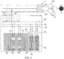
Figure 2 shows a schematic how to connect the batteries of the mining vehicle. The electric system of the mining vehicle may comprise two or more even numbered amount of batteries. In drive mode of the mining vehicle, the batteries are connected in parallel. In charge mode of the mining vehicle, the batteries are connected in series. - The contactors K1, K2, K4, K5, K6, K7 and K8 are connecting means that are used for providing the connecting in parallel and the connecting in series. Contactor K1 is a positive pole charging contactor and contactor K2 is a negative pole charging contactor. Contactors K4 and K6 are used for positive pole disconnection for charging busbars. Contactors K5 and K7 are used for negative pole disconnection for charging busbars. Contactor K8 is a neutral pole connection device for charging busbars.
- The
control unit 9 controls the contactors. The battery energy for use is taken from thedrive mode output 9 depicted in theFigure 2 . - Referring to the
Figure 2 , while batteries are parallel-connected, the charging contactors K1, and K2 are open (not contacting), contactors K4, K5, K6, and K7 are closed (contacting), and K8 is open (not contacting). - To ready the batteries for bipolar charging, contactors K4, K5, K6, and K7 are opened (break contact), after which the contactor K8 is closed (make contact). When charging is started, the contactors K1 and K2 are closed (make contact).
- It should be noted that the bipolar charging of the batteries does not necessarily require a neutral point connection from the charging system because the batteries are normally parallel-connected and share the same SOC and voltage. The neutral point N is at 0V inherently.
-
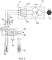
Figure 3 shows a solution similar to shown inFigure 1 but with an improvement relating to voltage balance. In addition to thepositive pole connector 2a and thenegative pole connector 2b, the mining vehicle comprises aneutral point connector 2c. Theneutral point connector 2c connects the centreline or 0 V or neutral point of thebipolar LVDC supply 1 to the mining vehicle. - The improved voltage balance using the neutral point in the LVDC supply is advantageous especially if the mining vehicle comprises odd number of traction motors, for example. Further balancing may be performed using the
brake resistors DC converters - The
bipolar LVDC supply 1 is supplied from anelectric grid 11. Thebipolar LVDC supply 1 may comprise atransformer 12. InFigure 3 thetransformer 12 comprises twosecondaries transformer 12 is one. According to another embodiment the number of the secondaries of thetransformer 12 is more than two. - The
bipolar LVDC supply 1 further comprises afirst converter 13a and asecond converter 13b. Thefirst converter 13a and thesecond converter 13b are connected in series whereby the neutral point is arranged between the first and second converters. Thereby the centerline of the mining vehicle is effectively balanced and thus the voltage balance is maintained on a high level. - Instead of the converters in series, as shown in
Figure 3 , the bipolar LVDC supply with the neutral point may also be provided using one converter. In such case the converter may be a three level NPC (Neutral-Point-Clamped) inverter, for example. -
Figure 4 shows a solution where the improvement relating to voltage balance is implemented in a manner similar to the solution inFigure 3 . In addition to the positive pole charging contactor K1 and the negative pole charging contactor K2 the mining vehicle comprises a neutral pole charging contactor K3. - In the solution shown in
Figure 2 different voltage levels in thebatteries Figure 4 provides for the voltage balance and thereby protects the charger itself, for example. - According to an embodiment the mining vehicle may comprise a three level NPC inverter or any other multi level inverter for driving a motor having a higher voltage level. Such a motor may be connected between the positive pole and the negative pole and possibly to the neutral pole, also.
- Thus, an energy unit may be connected between the positive pole and the negative pole with neutral connection using a three level NPC inverter, for example. If such an energy unit is bipolar as such and comprises a neutral point or it comprises components connected in series over which the voltage divides naturally, the components of the energy unit need to tolerate a lower voltage, only. Thus, the energy unit connected to a part of said certain total voltage may comprise a traction motor and/or a battery and/or any other electrical component.
- It will be obvious to a person skilled in the art that, as technology advances, the inventive concept can be implemented in various ways. The invention and its embodiments are not limited to the examples described above but may vary within the scope of the claims.
Claims (14)
- A system for supplying electric energy to a mining vehicle, the system comprising a bipolar LVDC supply having a certain total voltage and the mining vehicle, the mining vehicle comprising at least a first energy unit and a second energy unit, the first energy unit being connected to a part of said certain total voltage and the second energy unit being connected to another part of said certain total voltage.
- A system as claimed in claim 1, wherein the bipolar LVDC supply comprises a positive pole and a negative pole and a neutral point between the positive pole and the negative pole and the first energy unit is connected between the positive pole and the neutral point and the second energy unit is connected between the negative pole and the neutral point.
- A system as claimed in claim 2, wherein the bipolar LVDC supply comprises a first converter and a second converter connected in series whereby the neutral point is arranged between the first and second converters.
- A system as claimed in any one of the preceding claims, wherein the first energy unit and the second energy unit comprise traction motors of the mining vehicle.
- A system as claimed in any one of the preceding claims, wherein the first energy unit and the second energy unit comprise batteries, the mining vehicle comprising connecting means and a control unit, the control unit being arranged to connect the batteries in parallel in drive mode and arranged to connect the batteries in series in charge mode.
- A method of supplying electric energy to a mining vehicle, the mining vehicle comprising at least a first energy unit and a second energy unit, the method comprising supplying electric energy to the mining vehicle from a bipolar LVDC supply having a certain total voltage, connecting the first energy unit to a part of said certain total voltage and connecting the second energy unit to another part of said certain total voltage.
- A method as claimed in claim 6, wherein the first energy unit is connected between a positive pole of the bipolar LVDC supply and a neutral point of the bipolar LVDC supply and the second energy unit is connected between a negative pole of the bipolar LVDC supply and the neutral point.
- A method as claimed in claim 7, wherein the bipolar LVDC supply is formed by connecting a first converter and a second converter in series and arranging the neutral point between the first and second converters.
- A method as claimed in any one of the claims 6 to 8, wherein the first energy unit and the second energy unit comprise traction motors of the mining vehicle.
- A method as claimed in any one of the claims 6 to 9, wherein the first energy unit and the second energy unit comprise batteries and the batteries are connected in parallel in drive mode and the batteries are connected in series in charge mode.
- A mining vehicle, comprising at least a first energy unit, a second energy unit and connecting means for connecting the first energy unit to a part of a certain total voltage of a bipolar LVDC supply and the second energy unit to another part of said certain total voltage.
- A mining vehicle as claimed in claim 11, wherein the connecting means comprise a positive pole connector, a neutral point connector and a negative pole connector for connecting the first energy unit between the positive pole and the neutral point and the second energy unit between the negative pole and the neutral point.
- A mining vehicle as claimed in claim 11 or 12, wherein the first energy unit and the second energy unit comprise traction motors of the mining vehicle.
- A mining vehicle as claimed in any one of the claims 11 to 13, wherein the first energy unit and the second energy unit comprise batteries, the mining vehicle comprising connecting means and a control unit, the control unit being arranged to connect the batteries in parallel in drive mode and arranged to connect the batteries in series in charge mode.
Priority Applications (10)
| Application Number | Priority Date | Filing Date | Title |
|---|---|---|---|
| EP18173724.8A EP3572269B1 (en) | 2018-05-23 | 2018-05-23 | System and method for supplying electric energy to a mining vehicle and a mining vehicle |
| PL18173724T PL3572269T3 (en) | 2018-05-23 | 2018-05-23 | System and method for supplying electric energy to a mining vehicle and a mining vehicle |
| PCT/EP2019/062640 WO2019224102A1 (en) | 2018-05-23 | 2019-05-16 | System and method for supplying electric energy to a mining vehicle and a mining vehicle |
| AU2019272626A AU2019272626B2 (en) | 2018-05-23 | 2019-05-16 | System and method for supplying electric energy to a mining vehicle and a mining vehicle |
| MX2020012582A MX2020012582A (en) | 2018-05-23 | 2019-05-16 | System and method for supplying electric energy to a mining vehicle and a mining vehicle. |
| RU2020142235A RU2752149C1 (en) | 2018-05-23 | 2019-05-16 | System and method for supplying electrical energy to a mining vehicle and a mining vehicle |
| US17/057,387 US11305656B2 (en) | 2018-05-23 | 2019-05-16 | System and method for supplying electric energy to a mining vehicle and a mining vehicle |
| CA3099938A CA3099938C (en) | 2018-05-23 | 2019-05-16 | System and method for supplying electric energy to a mining vehicle and a mining vehicle |
| CN201980034365.7A CN112154080B (en) | 2018-05-23 | 2019-05-16 | System and method for supplying electric energy to a mining vehicle and mining vehicle |
| CL2020003027A CL2020003027A1 (en) | 2018-05-23 | 2020-11-20 | System and method for supplying electrical energy to a mining vehicle and a mining vehicle; vehicle. |
Applications Claiming Priority (1)
| Application Number | Priority Date | Filing Date | Title |
|---|---|---|---|
| EP18173724.8A EP3572269B1 (en) | 2018-05-23 | 2018-05-23 | System and method for supplying electric energy to a mining vehicle and a mining vehicle |
Publications (2)
| Publication Number | Publication Date |
|---|---|
| EP3572269A1 true EP3572269A1 (en) | 2019-11-27 |
| EP3572269B1 EP3572269B1 (en) | 2021-10-20 |
Family
ID=62235851
Family Applications (1)
| Application Number | Title | Priority Date | Filing Date |
|---|---|---|---|
| EP18173724.8A Active EP3572269B1 (en) | 2018-05-23 | 2018-05-23 | System and method for supplying electric energy to a mining vehicle and a mining vehicle |
Country Status (10)
| Country | Link |
|---|---|
| US (1) | US11305656B2 (en) |
| EP (1) | EP3572269B1 (en) |
| CN (1) | CN112154080B (en) |
| AU (1) | AU2019272626B2 (en) |
| CA (1) | CA3099938C (en) |
| CL (1) | CL2020003027A1 (en) |
| MX (1) | MX2020012582A (en) |
| PL (1) | PL3572269T3 (en) |
| RU (1) | RU2752149C1 (en) |
| WO (1) | WO2019224102A1 (en) |
Cited By (5)
| Publication number | Priority date | Publication date | Assignee | Title |
|---|---|---|---|---|
| EP3932725A1 (en) * | 2020-07-02 | 2022-01-05 | Siemens Aktiengesellschaft | Hybrid energy storage for high power and energy demanding mining and railway vehicles |
| EP3975380A3 (en) * | 2020-09-29 | 2022-04-20 | Samsung SDI Co., Ltd. | Battery control device and short circuit detection method thereof |
| CN116194324A (en) * | 2020-10-02 | 2023-05-30 | 采埃孚商用车系统全球有限公司 | Method, processing unit and vehicle for exchanging electrical energy |
| WO2023151809A1 (en) * | 2022-02-11 | 2023-08-17 | Abb Schweiz Ag | Electrical traction system for an industrial electric vehicle, industrial electric vehicle, electrical power supply system and method of providing electrical energy to an industrial electric vehicle |
| WO2025170492A1 (en) * | 2024-02-07 | 2025-08-14 | Epiroc Rock Drills Aktiebolag | An electrical power system for a mining/construction |
Families Citing this family (5)
| Publication number | Priority date | Publication date | Assignee | Title |
|---|---|---|---|---|
| US11870249B2 (en) | 2018-05-24 | 2024-01-09 | Hamilton Sundstrand Corporation | Electrical power system including energy storage modules and shared system controller |
| US11453309B2 (en) * | 2018-09-06 | 2022-09-27 | Artisan Vehicle Systems, Inc. | Electric power distribution system and method for electric mining machine |
| EP4511943A4 (en) * | 2022-04-22 | 2026-04-29 | Form Energy Inc | BATTERY STRIP CONFIGURATION |
| US12427871B2 (en) * | 2023-10-20 | 2025-09-30 | Caterpillar Inc. | Systems and methods for operating a divided power distribution system |
| WO2026071942A1 (en) * | 2024-09-25 | 2026-04-02 | Epiroc Rock Drills Aktiebolag | Energy source system for mining and/or construction machines |
Citations (4)
| Publication number | Priority date | Publication date | Assignee | Title |
|---|---|---|---|---|
| US20070139012A1 (en) * | 2005-11-01 | 2007-06-21 | Aerovironment, Inc. | Motive power dual battery pack |
| US20090079384A1 (en) * | 2007-09-24 | 2009-03-26 | Harris Scott C | Charging Control in an Electric Vehicle |
| WO2011080392A1 (en) * | 2009-12-28 | 2011-07-07 | Sandvik Mining And Construction Oy | Mining vehicle and method for its energy supply |
| US20130020982A1 (en) * | 2010-02-05 | 2013-01-24 | Commissariat A L'energie Atomique Et Aux Energies Alternatives | Equalization system for accumulator batteries |
Family Cites Families (13)
| Publication number | Priority date | Publication date | Assignee | Title |
|---|---|---|---|---|
| JP4993035B2 (en) * | 2009-05-14 | 2012-08-08 | トヨタ自動車株式会社 | Electric vehicle and control method thereof |
| JP4744622B2 (en) * | 2009-07-01 | 2011-08-10 | トヨタ自動車株式会社 | Vehicle control device |
| FR2982090B1 (en) * | 2011-10-31 | 2013-12-20 | Commissariat Energie Atomique | CHARGE BALANCING DEVICE FOR ELEMENTS OF A POWER BATTERY |
| WO2013133815A2 (en) * | 2012-03-07 | 2013-09-12 | International Truck Intellectual Property Company, Llc | Vehicle electrical system state controller |
| US9548619B2 (en) * | 2013-03-14 | 2017-01-17 | Solaredge Technologies Ltd. | Method and apparatus for storing and depleting energy |
| CN103904670B (en) * | 2014-04-14 | 2016-06-01 | 东南大学 | Flywheel energy storage system two-way changing device and control method thereof |
| FR3029709B1 (en) * | 2014-12-05 | 2018-01-19 | Valeo Equipements Electriques Moteur | POWER SUPPLY DEVICE AND IMPROVED CONTINUOUS VOLTAGE CONVERTER |
| RU162500U1 (en) * | 2015-01-30 | 2016-06-10 | Общество с ограниченной ответственностью НПФ "Арс Терм" | ELECTRIC VEHICLE VEHICLE |
| DE102015205278A1 (en) * | 2015-03-24 | 2016-09-29 | Robert Bosch Gmbh | Power network for an electrically driven motor vehicle |
| JP2017152923A (en) * | 2016-02-24 | 2017-08-31 | 株式会社デンソー | Load drive device |
| US10442306B2 (en) * | 2016-04-19 | 2019-10-15 | Faraday & Future Inc. | Vehicle power management |
| US10525833B2 (en) * | 2017-08-14 | 2020-01-07 | Hamilton Sundstrand Corporation | Tactical vehicle to grid electric power architecture |
| US11128147B2 (en) * | 2018-04-04 | 2021-09-21 | Bloom Energy Corporation | Power system integrated with dual power electrical load |
-
2018
- 2018-05-23 PL PL18173724T patent/PL3572269T3/en unknown
- 2018-05-23 EP EP18173724.8A patent/EP3572269B1/en active Active
-
2019
- 2019-05-16 WO PCT/EP2019/062640 patent/WO2019224102A1/en not_active Ceased
- 2019-05-16 CN CN201980034365.7A patent/CN112154080B/en active Active
- 2019-05-16 MX MX2020012582A patent/MX2020012582A/en unknown
- 2019-05-16 RU RU2020142235A patent/RU2752149C1/en active
- 2019-05-16 CA CA3099938A patent/CA3099938C/en active Active
- 2019-05-16 AU AU2019272626A patent/AU2019272626B2/en active Active
- 2019-05-16 US US17/057,387 patent/US11305656B2/en active Active
-
2020
- 2020-11-20 CL CL2020003027A patent/CL2020003027A1/en unknown
Patent Citations (4)
| Publication number | Priority date | Publication date | Assignee | Title |
|---|---|---|---|---|
| US20070139012A1 (en) * | 2005-11-01 | 2007-06-21 | Aerovironment, Inc. | Motive power dual battery pack |
| US20090079384A1 (en) * | 2007-09-24 | 2009-03-26 | Harris Scott C | Charging Control in an Electric Vehicle |
| WO2011080392A1 (en) * | 2009-12-28 | 2011-07-07 | Sandvik Mining And Construction Oy | Mining vehicle and method for its energy supply |
| US20130020982A1 (en) * | 2010-02-05 | 2013-01-24 | Commissariat A L'energie Atomique Et Aux Energies Alternatives | Equalization system for accumulator batteries |
Cited By (6)
| Publication number | Priority date | Publication date | Assignee | Title |
|---|---|---|---|---|
| EP3932725A1 (en) * | 2020-07-02 | 2022-01-05 | Siemens Aktiengesellschaft | Hybrid energy storage for high power and energy demanding mining and railway vehicles |
| EP3975380A3 (en) * | 2020-09-29 | 2022-04-20 | Samsung SDI Co., Ltd. | Battery control device and short circuit detection method thereof |
| US12500428B2 (en) | 2020-09-29 | 2025-12-16 | Samsung Sdi Co., Ltd. | Battery control device and short-circuit detection method thereof |
| CN116194324A (en) * | 2020-10-02 | 2023-05-30 | 采埃孚商用车系统全球有限公司 | Method, processing unit and vehicle for exchanging electrical energy |
| WO2023151809A1 (en) * | 2022-02-11 | 2023-08-17 | Abb Schweiz Ag | Electrical traction system for an industrial electric vehicle, industrial electric vehicle, electrical power supply system and method of providing electrical energy to an industrial electric vehicle |
| WO2025170492A1 (en) * | 2024-02-07 | 2025-08-14 | Epiroc Rock Drills Aktiebolag | An electrical power system for a mining/construction |
Also Published As
| Publication number | Publication date |
|---|---|
| EP3572269B1 (en) | 2021-10-20 |
| CA3099938A1 (en) | 2019-11-28 |
| CN112154080A (en) | 2020-12-29 |
| WO2019224102A1 (en) | 2019-11-28 |
| AU2019272626A1 (en) | 2021-01-14 |
| CA3099938C (en) | 2025-03-11 |
| PL3572269T3 (en) | 2022-02-07 |
| US20210197679A1 (en) | 2021-07-01 |
| CL2020003027A1 (en) | 2021-05-28 |
| AU2019272626B2 (en) | 2025-02-13 |
| US11305656B2 (en) | 2022-04-19 |
| MX2020012582A (en) | 2021-01-29 |
| CN112154080B (en) | 2023-05-26 |
| RU2752149C1 (en) | 2021-07-23 |
Similar Documents
| Publication | Publication Date | Title |
|---|---|---|
| US11305656B2 (en) | System and method for supplying electric energy to a mining vehicle and a mining vehicle | |
| CN110816300B (en) | Vehicle and electrical system with dual battery module | |
| US10093167B2 (en) | Electric or hybrid electric vehicle having multiple drive units arranged in separate parts of the vehicle | |
| CN112498176B (en) | Electric powertrain with multi-pack battery system | |
| US10500980B2 (en) | Modular battery pack system with series and parallel charging and propulsion modes | |
| EP3543063B1 (en) | High voltage electrical system for a vehicle and method of controlling the system | |
| CN114312731B (en) | Electric drive train with battery system having multi-pole high-voltage contactors | |
| CN114312480B (en) | Electrodynamic assembly with multiple battery cell system and mutually exclusive three-way contactor | |
| CN104302506B (en) | Motor vehicles with high-voltage power supply systems | |
| US12054061B2 (en) | Electric propulsion system for a vehicle | |
| EP4580905A1 (en) | State of charge balancing in split battery system | |
| US20250170902A1 (en) | Electrical traction system for an industrial electric vehicle, industrial electric vehicle, electrical power supply system and method of providing electrical energy to an industrial electric vehicle | |
| WO2018013036A1 (en) | Vehicle with ac outlet |
Legal Events
| Date | Code | Title | Description |
|---|---|---|---|
| PUAI | Public reference made under article 153(3) epc to a published international application that has entered the european phase |
Free format text: ORIGINAL CODE: 0009012 |
|
| STAA | Information on the status of an ep patent application or granted ep patent |
Free format text: STATUS: THE APPLICATION HAS BEEN PUBLISHED |
|
| AK | Designated contracting states |
Kind code of ref document: A1 Designated state(s): AL AT BE BG CH CY CZ DE DK EE ES FI FR GB GR HR HU IE IS IT LI LT LU LV MC MK MT NL NO PL PT RO RS SE SI SK SM TR |
|
| AX | Request for extension of the european patent |
Extension state: BA ME |
|
| STAA | Information on the status of an ep patent application or granted ep patent |
Free format text: STATUS: REQUEST FOR EXAMINATION WAS MADE |
|
| 17P | Request for examination filed |
Effective date: 20200527 |
|
| RBV | Designated contracting states (corrected) |
Designated state(s): AL AT BE BG CH CY CZ DE DK EE ES FI FR GB GR HR HU IE IS IT LI LT LU LV MC MK MT NL NO PL PT RO RS SE SI SK SM TR |
|
| REG | Reference to a national code |
Ref country code: DE Ref legal event code: R079 Ref document number: 602018025200 Country of ref document: DE Free format text: PREVIOUS MAIN CLASS: B60L0011180000 Ipc: B60L0053140000 |
|
| RIC1 | Information provided on ipc code assigned before grant |
Ipc: H02J 7/00 20060101ALI20210617BHEP Ipc: H02J 1/08 20060101ALI20210617BHEP Ipc: B60L 58/19 20190101ALI20210617BHEP Ipc: B60L 50/53 20190101ALI20210617BHEP Ipc: B60L 53/14 20190101AFI20210617BHEP |
|
| GRAP | Despatch of communication of intention to grant a patent |
Free format text: ORIGINAL CODE: EPIDOSNIGR1 |
|
| STAA | Information on the status of an ep patent application or granted ep patent |
Free format text: STATUS: GRANT OF PATENT IS INTENDED |
|
| INTG | Intention to grant announced |
Effective date: 20210809 |
|
| GRAS | Grant fee paid |
Free format text: ORIGINAL CODE: EPIDOSNIGR3 |
|
| GRAA | (expected) grant |
Free format text: ORIGINAL CODE: 0009210 |
|
| STAA | Information on the status of an ep patent application or granted ep patent |
Free format text: STATUS: THE PATENT HAS BEEN GRANTED |
|
| AK | Designated contracting states |
Kind code of ref document: B1 Designated state(s): AL AT BE BG CH CY CZ DE DK EE ES FI FR GB GR HR HU IE IS IT LI LT LU LV MC MK MT NL NO PL PT RO RS SE SI SK SM TR |
|
| REG | Reference to a national code |
Ref country code: GB Ref legal event code: FG4D |
|
| REG | Reference to a national code |
Ref country code: CH Ref legal event code: EP |
|
| REG | Reference to a national code |
Ref country code: DE Ref legal event code: R096 Ref document number: 602018025200 Country of ref document: DE |
|
| REG | Reference to a national code |
Ref country code: IE Ref legal event code: FG4D |
|
| REG | Reference to a national code |
Ref country code: AT Ref legal event code: REF Ref document number: 1439665 Country of ref document: AT Kind code of ref document: T Effective date: 20211115 |
|
| REG | Reference to a national code |
Ref country code: FI Ref legal event code: FGE |
|
| REG | Reference to a national code |
Ref country code: SE Ref legal event code: TRGR |
|
| REG | Reference to a national code |
Ref country code: LT Ref legal event code: MG9D |
|
| REG | Reference to a national code |
Ref country code: NL Ref legal event code: MP Effective date: 20211020 |
|
| REG | Reference to a national code |
Ref country code: AT Ref legal event code: MK05 Ref document number: 1439665 Country of ref document: AT Kind code of ref document: T Effective date: 20211020 |
|
| PG25 | Lapsed in a contracting state [announced via postgrant information from national office to epo] |
Ref country code: RS Free format text: LAPSE BECAUSE OF FAILURE TO SUBMIT A TRANSLATION OF THE DESCRIPTION OR TO PAY THE FEE WITHIN THE PRESCRIBED TIME-LIMIT Effective date: 20211020 Ref country code: LT Free format text: LAPSE BECAUSE OF FAILURE TO SUBMIT A TRANSLATION OF THE DESCRIPTION OR TO PAY THE FEE WITHIN THE PRESCRIBED TIME-LIMIT Effective date: 20211020 Ref country code: BG Free format text: LAPSE BECAUSE OF FAILURE TO SUBMIT A TRANSLATION OF THE DESCRIPTION OR TO PAY THE FEE WITHIN THE PRESCRIBED TIME-LIMIT Effective date: 20220120 Ref country code: AT Free format text: LAPSE BECAUSE OF FAILURE TO SUBMIT A TRANSLATION OF THE DESCRIPTION OR TO PAY THE FEE WITHIN THE PRESCRIBED TIME-LIMIT Effective date: 20211020 |
|
| PG25 | Lapsed in a contracting state [announced via postgrant information from national office to epo] |
Ref country code: IS Free format text: LAPSE BECAUSE OF FAILURE TO SUBMIT A TRANSLATION OF THE DESCRIPTION OR TO PAY THE FEE WITHIN THE PRESCRIBED TIME-LIMIT Effective date: 20220220 Ref country code: PT Free format text: LAPSE BECAUSE OF FAILURE TO SUBMIT A TRANSLATION OF THE DESCRIPTION OR TO PAY THE FEE WITHIN THE PRESCRIBED TIME-LIMIT Effective date: 20220221 Ref country code: NO Free format text: LAPSE BECAUSE OF FAILURE TO SUBMIT A TRANSLATION OF THE DESCRIPTION OR TO PAY THE FEE WITHIN THE PRESCRIBED TIME-LIMIT Effective date: 20220120 Ref country code: NL Free format text: LAPSE BECAUSE OF FAILURE TO SUBMIT A TRANSLATION OF THE DESCRIPTION OR TO PAY THE FEE WITHIN THE PRESCRIBED TIME-LIMIT Effective date: 20211020 Ref country code: LV Free format text: LAPSE BECAUSE OF FAILURE TO SUBMIT A TRANSLATION OF THE DESCRIPTION OR TO PAY THE FEE WITHIN THE PRESCRIBED TIME-LIMIT Effective date: 20211020 Ref country code: HR Free format text: LAPSE BECAUSE OF FAILURE TO SUBMIT A TRANSLATION OF THE DESCRIPTION OR TO PAY THE FEE WITHIN THE PRESCRIBED TIME-LIMIT Effective date: 20211020 Ref country code: GR Free format text: LAPSE BECAUSE OF FAILURE TO SUBMIT A TRANSLATION OF THE DESCRIPTION OR TO PAY THE FEE WITHIN THE PRESCRIBED TIME-LIMIT Effective date: 20220121 Ref country code: ES Free format text: LAPSE BECAUSE OF FAILURE TO SUBMIT A TRANSLATION OF THE DESCRIPTION OR TO PAY THE FEE WITHIN THE PRESCRIBED TIME-LIMIT Effective date: 20211020 |
|
| REG | Reference to a national code |
Ref country code: DE Ref legal event code: R097 Ref document number: 602018025200 Country of ref document: DE |
|
| PG25 | Lapsed in a contracting state [announced via postgrant information from national office to epo] |
Ref country code: SM Free format text: LAPSE BECAUSE OF FAILURE TO SUBMIT A TRANSLATION OF THE DESCRIPTION OR TO PAY THE FEE WITHIN THE PRESCRIBED TIME-LIMIT Effective date: 20211020 Ref country code: SK Free format text: LAPSE BECAUSE OF FAILURE TO SUBMIT A TRANSLATION OF THE DESCRIPTION OR TO PAY THE FEE WITHIN THE PRESCRIBED TIME-LIMIT Effective date: 20211020 Ref country code: RO Free format text: LAPSE BECAUSE OF FAILURE TO SUBMIT A TRANSLATION OF THE DESCRIPTION OR TO PAY THE FEE WITHIN THE PRESCRIBED TIME-LIMIT Effective date: 20211020 Ref country code: EE Free format text: LAPSE BECAUSE OF FAILURE TO SUBMIT A TRANSLATION OF THE DESCRIPTION OR TO PAY THE FEE WITHIN THE PRESCRIBED TIME-LIMIT Effective date: 20211020 Ref country code: DK Free format text: LAPSE BECAUSE OF FAILURE TO SUBMIT A TRANSLATION OF THE DESCRIPTION OR TO PAY THE FEE WITHIN THE PRESCRIBED TIME-LIMIT Effective date: 20211020 |
|
| PLBE | No opposition filed within time limit |
Free format text: ORIGINAL CODE: 0009261 |
|
| STAA | Information on the status of an ep patent application or granted ep patent |
Free format text: STATUS: NO OPPOSITION FILED WITHIN TIME LIMIT |
|
| 26N | No opposition filed |
Effective date: 20220721 |
|
| PG25 | Lapsed in a contracting state [announced via postgrant information from national office to epo] |
Ref country code: AL Free format text: LAPSE BECAUSE OF FAILURE TO SUBMIT A TRANSLATION OF THE DESCRIPTION OR TO PAY THE FEE WITHIN THE PRESCRIBED TIME-LIMIT Effective date: 20211020 |
|
| PG25 | Lapsed in a contracting state [announced via postgrant information from national office to epo] |
Ref country code: SI Free format text: LAPSE BECAUSE OF FAILURE TO SUBMIT A TRANSLATION OF THE DESCRIPTION OR TO PAY THE FEE WITHIN THE PRESCRIBED TIME-LIMIT Effective date: 20211020 |
|
| REG | Reference to a national code |
Ref country code: CH Ref legal event code: PL |
|
| REG | Reference to a national code |
Ref country code: BE Ref legal event code: MM Effective date: 20220531 |
|
| GBPC | Gb: european patent ceased through non-payment of renewal fee |
Effective date: 20220523 |
|
| PG25 | Lapsed in a contracting state [announced via postgrant information from national office to epo] |
Ref country code: MC Free format text: LAPSE BECAUSE OF FAILURE TO SUBMIT A TRANSLATION OF THE DESCRIPTION OR TO PAY THE FEE WITHIN THE PRESCRIBED TIME-LIMIT Effective date: 20211020 Ref country code: LU Free format text: LAPSE BECAUSE OF NON-PAYMENT OF DUE FEES Effective date: 20220523 Ref country code: LI Free format text: LAPSE BECAUSE OF NON-PAYMENT OF DUE FEES Effective date: 20220531 Ref country code: CH Free format text: LAPSE BECAUSE OF NON-PAYMENT OF DUE FEES Effective date: 20220531 |
|
| PG25 | Lapsed in a contracting state [announced via postgrant information from national office to epo] |
Ref country code: IE Free format text: LAPSE BECAUSE OF NON-PAYMENT OF DUE FEES Effective date: 20220523 |
|
| PG25 | Lapsed in a contracting state [announced via postgrant information from national office to epo] |
Ref country code: IT Free format text: LAPSE BECAUSE OF FAILURE TO SUBMIT A TRANSLATION OF THE DESCRIPTION OR TO PAY THE FEE WITHIN THE PRESCRIBED TIME-LIMIT Effective date: 20211020 Ref country code: GB Free format text: LAPSE BECAUSE OF NON-PAYMENT OF DUE FEES Effective date: 20220523 Ref country code: BE Free format text: LAPSE BECAUSE OF NON-PAYMENT OF DUE FEES Effective date: 20220531 |
|
| P01 | Opt-out of the competence of the unified patent court (upc) registered |
Effective date: 20230603 |
|
| PG25 | Lapsed in a contracting state [announced via postgrant information from national office to epo] |
Ref country code: HU Free format text: LAPSE BECAUSE OF FAILURE TO SUBMIT A TRANSLATION OF THE DESCRIPTION OR TO PAY THE FEE WITHIN THE PRESCRIBED TIME-LIMIT; INVALID AB INITIO Effective date: 20180523 |
|
| PG25 | Lapsed in a contracting state [announced via postgrant information from national office to epo] |
Ref country code: MK Free format text: LAPSE BECAUSE OF FAILURE TO SUBMIT A TRANSLATION OF THE DESCRIPTION OR TO PAY THE FEE WITHIN THE PRESCRIBED TIME-LIMIT Effective date: 20211020 Ref country code: CY Free format text: LAPSE BECAUSE OF FAILURE TO SUBMIT A TRANSLATION OF THE DESCRIPTION OR TO PAY THE FEE WITHIN THE PRESCRIBED TIME-LIMIT Effective date: 20211020 |
|
| PG25 | Lapsed in a contracting state [announced via postgrant information from national office to epo] |
Ref country code: TR Free format text: LAPSE BECAUSE OF FAILURE TO SUBMIT A TRANSLATION OF THE DESCRIPTION OR TO PAY THE FEE WITHIN THE PRESCRIBED TIME-LIMIT Effective date: 20211020 |
|
| PG25 | Lapsed in a contracting state [announced via postgrant information from national office to epo] |
Ref country code: MT Free format text: LAPSE BECAUSE OF FAILURE TO SUBMIT A TRANSLATION OF THE DESCRIPTION OR TO PAY THE FEE WITHIN THE PRESCRIBED TIME-LIMIT Effective date: 20211020 |
|
| PGFP | Annual fee paid to national office [announced via postgrant information from national office to epo] |
Ref country code: FI Payment date: 20250513 Year of fee payment: 8 |
|
| PGFP | Annual fee paid to national office [announced via postgrant information from national office to epo] |
Ref country code: PL Payment date: 20250414 Year of fee payment: 8 Ref country code: DE Payment date: 20250402 Year of fee payment: 8 |
|
| PGFP | Annual fee paid to national office [announced via postgrant information from national office to epo] |
Ref country code: FR Payment date: 20250422 Year of fee payment: 8 |
|
| PGFP | Annual fee paid to national office [announced via postgrant information from national office to epo] |
Ref country code: CZ Payment date: 20250423 Year of fee payment: 8 |
|
| PGFP | Annual fee paid to national office [announced via postgrant information from national office to epo] |
Ref country code: SE Payment date: 20250411 Year of fee payment: 8 |