EP3572180A1 - Method of laser welding of metal plates - Google Patents
Method of laser welding of metal plates Download PDFInfo
- Publication number
- EP3572180A1 EP3572180A1 EP19169934.7A EP19169934A EP3572180A1 EP 3572180 A1 EP3572180 A1 EP 3572180A1 EP 19169934 A EP19169934 A EP 19169934A EP 3572180 A1 EP3572180 A1 EP 3572180A1
- Authority
- EP
- European Patent Office
- Prior art keywords
- laser beam
- laser
- scanning locus
- metal plates
- metal
- Prior art date
- Legal status (The legal status is an assumption and is not a legal conclusion. Google has not performed a legal analysis and makes no representation as to the accuracy of the status listed.)
- Granted
Links
- 238000000034 method Methods 0.000 title claims abstract description 50
- 238000004021 metal welding Methods 0.000 title 1
- 229910052751 metal Inorganic materials 0.000 claims abstract description 173
- 239000002184 metal Substances 0.000 claims abstract description 173
- 238000005304 joining Methods 0.000 claims abstract description 111
- 238000003466 welding Methods 0.000 claims abstract description 96
- 238000002844 melting Methods 0.000 claims description 3
- 230000008018 melting Effects 0.000 claims description 3
- 238000003756 stirring Methods 0.000 claims description 2
- 239000007769 metal material Substances 0.000 description 21
- 238000010586 diagram Methods 0.000 description 12
- 230000008859 change Effects 0.000 description 10
- XAGFODPZIPBFFR-UHFFFAOYSA-N aluminium Chemical compound [Al] XAGFODPZIPBFFR-UHFFFAOYSA-N 0.000 description 4
- 230000000694 effects Effects 0.000 description 4
- 239000000463 material Substances 0.000 description 4
- 238000002474 experimental method Methods 0.000 description 3
- 230000033001 locomotion Effects 0.000 description 3
- 238000004519 manufacturing process Methods 0.000 description 3
- 238000005204 segregation Methods 0.000 description 3
- 238000004088 simulation Methods 0.000 description 3
- CURLTUGMZLYLDI-UHFFFAOYSA-N Carbon dioxide Chemical compound O=C=O CURLTUGMZLYLDI-UHFFFAOYSA-N 0.000 description 2
- XEEYBQQBJWHFJM-UHFFFAOYSA-N Iron Chemical compound [Fe] XEEYBQQBJWHFJM-UHFFFAOYSA-N 0.000 description 2
- 229910052782 aluminium Inorganic materials 0.000 description 2
- 230000007547 defect Effects 0.000 description 2
- 230000001678 irradiating effect Effects 0.000 description 2
- 230000007246 mechanism Effects 0.000 description 2
- 239000013307 optical fiber Substances 0.000 description 2
- 230000009467 reduction Effects 0.000 description 2
- 230000004044 response Effects 0.000 description 2
- 229910000838 Al alloy Inorganic materials 0.000 description 1
- RYGMFSIKBFXOCR-UHFFFAOYSA-N Copper Chemical compound [Cu] RYGMFSIKBFXOCR-UHFFFAOYSA-N 0.000 description 1
- FYYHWMGAXLPEAU-UHFFFAOYSA-N Magnesium Chemical compound [Mg] FYYHWMGAXLPEAU-UHFFFAOYSA-N 0.000 description 1
- RTAQQCXQSZGOHL-UHFFFAOYSA-N Titanium Chemical compound [Ti] RTAQQCXQSZGOHL-UHFFFAOYSA-N 0.000 description 1
- 239000011324 bead Substances 0.000 description 1
- 229910002092 carbon dioxide Inorganic materials 0.000 description 1
- 239000001569 carbon dioxide Substances 0.000 description 1
- 238000001816 cooling Methods 0.000 description 1
- 229910052802 copper Inorganic materials 0.000 description 1
- 239000010949 copper Substances 0.000 description 1
- 230000003247 decreasing effect Effects 0.000 description 1
- 239000000835 fiber Substances 0.000 description 1
- 230000006872 improvement Effects 0.000 description 1
- 229910052742 iron Inorganic materials 0.000 description 1
- 238000003754 machining Methods 0.000 description 1
- 239000011777 magnesium Substances 0.000 description 1
- 229910052749 magnesium Inorganic materials 0.000 description 1
- 150000002739 metals Chemical class 0.000 description 1
- 239000010936 titanium Substances 0.000 description 1
- 229910052719 titanium Inorganic materials 0.000 description 1
Images




Classifications
-
- B—PERFORMING OPERATIONS; TRANSPORTING
- B23—MACHINE TOOLS; METAL-WORKING NOT OTHERWISE PROVIDED FOR
- B23K—SOLDERING OR UNSOLDERING; WELDING; CLADDING OR PLATING BY SOLDERING OR WELDING; CUTTING BY APPLYING HEAT LOCALLY, e.g. FLAME CUTTING; WORKING BY LASER BEAM
- B23K26/00—Working by laser beam, e.g. welding, cutting or boring
- B23K26/08—Devices involving relative movement between laser beam and workpiece
- B23K26/082—Scanning systems, i.e. devices involving movement of the laser beam relative to the laser head
-
- B—PERFORMING OPERATIONS; TRANSPORTING
- B23—MACHINE TOOLS; METAL-WORKING NOT OTHERWISE PROVIDED FOR
- B23K—SOLDERING OR UNSOLDERING; WELDING; CLADDING OR PLATING BY SOLDERING OR WELDING; CUTTING BY APPLYING HEAT LOCALLY, e.g. FLAME CUTTING; WORKING BY LASER BEAM
- B23K26/00—Working by laser beam, e.g. welding, cutting or boring
- B23K26/20—Bonding
- B23K26/21—Bonding by welding
-
- B—PERFORMING OPERATIONS; TRANSPORTING
- B23—MACHINE TOOLS; METAL-WORKING NOT OTHERWISE PROVIDED FOR
- B23K—SOLDERING OR UNSOLDERING; WELDING; CLADDING OR PLATING BY SOLDERING OR WELDING; CUTTING BY APPLYING HEAT LOCALLY, e.g. FLAME CUTTING; WORKING BY LASER BEAM
- B23K26/00—Working by laser beam, e.g. welding, cutting or boring
- B23K26/70—Auxiliary operations or equipment
- B23K26/702—Auxiliary equipment
- B23K26/703—Cooling arrangements
-
- B—PERFORMING OPERATIONS; TRANSPORTING
- B23—MACHINE TOOLS; METAL-WORKING NOT OTHERWISE PROVIDED FOR
- B23K—SOLDERING OR UNSOLDERING; WELDING; CLADDING OR PLATING BY SOLDERING OR WELDING; CUTTING BY APPLYING HEAT LOCALLY, e.g. FLAME CUTTING; WORKING BY LASER BEAM
- B23K26/00—Working by laser beam, e.g. welding, cutting or boring
- B23K26/02—Positioning or observing the workpiece, e.g. with respect to the point of impact; Aligning, aiming or focusing the laser beam
- B23K26/06—Shaping the laser beam, e.g. by masks or multi-focusing
- B23K26/062—Shaping the laser beam, e.g. by masks or multi-focusing by direct control of the laser beam
- B23K26/0622—Shaping the laser beam, e.g. by masks or multi-focusing by direct control of the laser beam by shaping pulses
-
- B—PERFORMING OPERATIONS; TRANSPORTING
- B23—MACHINE TOOLS; METAL-WORKING NOT OTHERWISE PROVIDED FOR
- B23K—SOLDERING OR UNSOLDERING; WELDING; CLADDING OR PLATING BY SOLDERING OR WELDING; CUTTING BY APPLYING HEAT LOCALLY, e.g. FLAME CUTTING; WORKING BY LASER BEAM
- B23K26/00—Working by laser beam, e.g. welding, cutting or boring
- B23K26/20—Bonding
- B23K26/21—Bonding by welding
- B23K26/22—Spot welding
-
- B—PERFORMING OPERATIONS; TRANSPORTING
- B23—MACHINE TOOLS; METAL-WORKING NOT OTHERWISE PROVIDED FOR
- B23K—SOLDERING OR UNSOLDERING; WELDING; CLADDING OR PLATING BY SOLDERING OR WELDING; CUTTING BY APPLYING HEAT LOCALLY, e.g. FLAME CUTTING; WORKING BY LASER BEAM
- B23K26/00—Working by laser beam, e.g. welding, cutting or boring
- B23K26/20—Bonding
- B23K26/21—Bonding by welding
- B23K26/24—Seam welding
-
- B—PERFORMING OPERATIONS; TRANSPORTING
- B23—MACHINE TOOLS; METAL-WORKING NOT OTHERWISE PROVIDED FOR
- B23K—SOLDERING OR UNSOLDERING; WELDING; CLADDING OR PLATING BY SOLDERING OR WELDING; CUTTING BY APPLYING HEAT LOCALLY, e.g. FLAME CUTTING; WORKING BY LASER BEAM
- B23K26/00—Working by laser beam, e.g. welding, cutting or boring
- B23K26/20—Bonding
- B23K26/21—Bonding by welding
- B23K26/24—Seam welding
- B23K26/28—Seam welding of curved planar seams
-
- B—PERFORMING OPERATIONS; TRANSPORTING
- B23—MACHINE TOOLS; METAL-WORKING NOT OTHERWISE PROVIDED FOR
- B23K—SOLDERING OR UNSOLDERING; WELDING; CLADDING OR PLATING BY SOLDERING OR WELDING; CUTTING BY APPLYING HEAT LOCALLY, e.g. FLAME CUTTING; WORKING BY LASER BEAM
- B23K26/00—Working by laser beam, e.g. welding, cutting or boring
- B23K26/20—Bonding
- B23K26/32—Bonding taking account of the properties of the material involved
-
- B—PERFORMING OPERATIONS; TRANSPORTING
- B23—MACHINE TOOLS; METAL-WORKING NOT OTHERWISE PROVIDED FOR
- B23K—SOLDERING OR UNSOLDERING; WELDING; CLADDING OR PLATING BY SOLDERING OR WELDING; CUTTING BY APPLYING HEAT LOCALLY, e.g. FLAME CUTTING; WORKING BY LASER BEAM
- B23K26/00—Working by laser beam, e.g. welding, cutting or boring
- B23K26/70—Auxiliary operations or equipment
-
- B—PERFORMING OPERATIONS; TRANSPORTING
- B23—MACHINE TOOLS; METAL-WORKING NOT OTHERWISE PROVIDED FOR
- B23K—SOLDERING OR UNSOLDERING; WELDING; CLADDING OR PLATING BY SOLDERING OR WELDING; CUTTING BY APPLYING HEAT LOCALLY, e.g. FLAME CUTTING; WORKING BY LASER BEAM
- B23K26/00—Working by laser beam, e.g. welding, cutting or boring
- B23K26/70—Auxiliary operations or equipment
- B23K26/702—Auxiliary equipment
-
- B—PERFORMING OPERATIONS; TRANSPORTING
- B23—MACHINE TOOLS; METAL-WORKING NOT OTHERWISE PROVIDED FOR
- B23K—SOLDERING OR UNSOLDERING; WELDING; CLADDING OR PLATING BY SOLDERING OR WELDING; CUTTING BY APPLYING HEAT LOCALLY, e.g. FLAME CUTTING; WORKING BY LASER BEAM
- B23K2101/00—Articles made by soldering, welding or cutting
- B23K2101/006—Vehicles
-
- B—PERFORMING OPERATIONS; TRANSPORTING
- B23—MACHINE TOOLS; METAL-WORKING NOT OTHERWISE PROVIDED FOR
- B23K—SOLDERING OR UNSOLDERING; WELDING; CLADDING OR PLATING BY SOLDERING OR WELDING; CUTTING BY APPLYING HEAT LOCALLY, e.g. FLAME CUTTING; WORKING BY LASER BEAM
- B23K2101/00—Articles made by soldering, welding or cutting
- B23K2101/18—Sheet panels
-
- B—PERFORMING OPERATIONS; TRANSPORTING
- B23—MACHINE TOOLS; METAL-WORKING NOT OTHERWISE PROVIDED FOR
- B23K—SOLDERING OR UNSOLDERING; WELDING; CLADDING OR PLATING BY SOLDERING OR WELDING; CUTTING BY APPLYING HEAT LOCALLY, e.g. FLAME CUTTING; WORKING BY LASER BEAM
- B23K2103/00—Materials to be soldered, welded or cut
- B23K2103/08—Non-ferrous metals or alloys
- B23K2103/10—Aluminium or alloys thereof
Definitions
- the present invention relates to a laser welding method for joining a plurality of metal plates superimposed on each other. Particularly, the present invention relates to improvement of an irradiation mode on a metal plate with a laser beam.
- Patent Document 1 discloses a method for welding two metal plates superimposed on each other, which includes the steps of: irradiating a surface of the metal plates with a laser beam; melting the metal plates to form a molten pool; and irradiating the molten pool with the laser beam to flow molten metal in the molten pool.
- the joining strength between the metal plates is ensured.
- Patent Document 1 JP 2012-228715 A
- a welding defect called as "burn through” may be generated. That is, the molten metal of the metal plate irradiated with the laser beam (i.e. an upper plate when the metal plates are superimposed on each other in the vertical direction) may fall toward the other metal plate (i.e. a lower plate when the metal plates are superimposed on each other in the vertical direction).
- an area of the joining region i.e.
- FIGS. 15 are diagrams illustrating a state of metal plates having an increased joining region during irradiation with the laser beam in the conventional laser welding.
- FIG. 15(a) is a cross-sectional view of the joining region of the metal plates and the laser beam.
- FIG. 15(b) is a plan view of the metal plates.
- the laser welding is performed in a state in which the gap formed between the metal plates (an upper plate a and a lower plate b ) is large, where the laser beam is indicated by the dashed dotted line.
- a molten metal c of the upper plate a hangs down toward the lower plate b.
- the molten metal c may be detached from the upper plate a to generate the "burn through", as shown in FIGS. 16 (diagrams illustrating a state in which the irradiation with the laser beam is completed, which respectively correspond to the diagrams of FIGS. 15 ). That is, in FIGS. 16 , the molten metal c is not bridged between the upper plate a and the lower plate b at the part enclosed by the circle indicated by the dashed double-dotted line, which means that a sufficient joining strength cannot be ensured.
- the present invention was made in consideration of the above problem, an object of which is to provide a laser welding method capable of ensuring a sufficient joining strength between metal plates by increasing an area of a joining region while preventing the "burn through" of a molten metal.
- a laser welding method for joining metal plates which includes the steps of: applying a laser beam to a surface of a plurality of metal plates superimposed on each other; melting the metal plates by scanning a position to be irradiated so as to make a molten pool constituted of the molten metal; stirring the molten pool by scanning with the laser beam; shifting sequentially a scanning locus to be scanned with the laser beam from an inner circular scanning locus to an outer circular scanning locus in a predetermined joining region on the metal plates; and providing an emission interval at the time of shifting the scanning locus to be scanned with the laser beam so that the irradiation on the surface of the metal plates with the laser beam is temporally stopped.
- the scanning with the laser beam (applying the laser beam) is performed along the inner circular scanning locus in the predetermined joining region on the metal plates so as to melt the metal (metal material) in the vicinity of the scanning locus.
- a molten pool constituted of the molten metal is scanned and stirred with the laser beam.
- the irradiation on the surface of the metal plates with the laser beam is temporally stopped when the scanning locus to be scanned with the laser beam is shifted to the outer circular scanning locus. In other words, after a certain emission interval (i.e.
- the scanning with the laser beam (applying the laser beam) is re-started along the outer circular scanning locus so as to melt the metal material in the vicinity of the outer circular scanning locus.
- a molten pool constituted of the molten metal is scanned and stirred with the laser beam.
- Such lowering of the temperature of the molten metal increases its viscosity, which leads to reduction in the mass of the metal molten by irradiation with the laser beam after the scanning locus to be scanned with the laser beam is shifted (i.e. the mass of the molten metal having the low viscosity is reduced).
- the mass of the molten metal having the low viscosity is reduced.
- the circular scanning loci are concentric circles centered at a central part of the joining region.
- the scanning with the laser beam is successively performed along the respective concentric circular scanning loci, and the irradiation on the surface of the metal plates with the laser beam is temporally stopped at the time of shifting the scanning locus. In this way, it is possible to realize the circular joining region having a large area while preventing the "burn through" of the molten metal.
- the output of the laser beam that is applied to the innermost circular scanning locus in the joining region is set larger than the output of the laser beam that is applied to any of the other circular scanning loci.
- the metal material of the joining region has not at all been molten yet.
- the metal material requires a large heat input in order to be molten compared to the case in which the laser beam is applied to any of the other scanning loci (i.e. the case in which the metal material has already been molten at the inner circular scanning locus).
- the output of the laser beam applied to the innermost circular scanning locus is set larger than the output of the laser beam applied to any of the other circular scanning loci, so that the metal material in the vicinity of the innermost circular scanning locus is effectively molten and the time required to perform the laser welding is shorten.
- the output of the laser beam applied to the one point of the central part is set larger than the output of the laser beam that is applied to any of the other circular scanning loci.
- the metal material of the joining region has not at all been molten yet.
- the metal material requires a large heat input in order to be molten.
- the length of the emission interval is set longer as the circular scanning locus to be scanned with the laser beam is shifted to the outer circular scanning locus.
- the subsequent irradiation with the laser beam i.e. application of the laser beam along the outer circular scanning locus
- the subsequent irradiation with the laser beam is performed before the molten metal has completely hardened, even when the emission interval is provided.
- the subsequent irradiation with the laser beam is performed on the metal plates in which heat is stored.
- the amount of heat stored in the metal plates has a tendency to increase as the irradiation with the laser beam is shifted between the adjacent two of the circular scanning loci on the outer side.
- the length of the emission interval is set longer as the circular scanning locus to be scanned with the laser beam is shifted to the outer one, so that hardening of the molten metal is accelerated (in other words, the viscosity is reduced). Therefore, the "burn through" of the molten metal is reliably prevented.
- the scanning locus to be scanned with the laser beam is sequentially shifted from an inner circular scanning locus to an outer circular scanning locus in a predetermined joining region on the metal plates, and an emission interval is provided at the time of shifting the scanning locus to be scanned with the laser beam so that the irradiation on the surface of the metal plates with the laser beam is temporally stopped.
- FIG. 1 is a schematic configuration diagram illustrating a laser welding apparatus 1 used for laser welding according to this embodiment.
- the laser welding apparatus 1 includes a laser oscillator 2, a laser scanner 3, a welding robot 4 and a robot controller 5.
- the laser oscillator 2 generates a laser beam.
- the generated laser beam is guided to the laser scanner 3 via an optical fiber cable 21. It is possible to use the laser beam such as a carbon dioxide laser, a YAG laser, or a fiber laser.
- the laser scanner 3 irradiates a workpiece W, which is formed by superimposing two plate materials made of aluminum alloy (aluminum metal plates, hereinafter occasionally referred to as simply "metal plates") W1 and W2 on each other, with the laser beam guided via the optical fiber cable 21 (see the dashed dotted line in FIG. 1 ).
- a plurality of lenses (not shown) and a plurality of mirrors 31 are housed.
- the laser scanner 3 includes, for example, a collimating lens to convert the laser beam into a parallel beam and a condensing lens to converge the laser beam such that the converged laser beam is focused on a machining point of the workpiece W (i.e. on a predetermined position irradiated with the laser beam on the workpiece W).
- each mirror 31 is rotatable about a rotary shaft 32.
- the rotary shaft 32 is coupled to a scanning motor 33, and the scanning motor 33 is activated to rotate the rotary shaft 32 that causes the mirror 31 to rotate.
- each of the mirrors 31 may, for example, be constituted of a galvanometer mirror.
- the laser welding according to this embodiment is a so-called laser screw welding (LSW). That is, a welding part (a joining region) of the workpiece W is scanned with the laser beam along a predetermined scanning locus so that the welding part is molten to be welded. The scanning with the laser beam is performed by the mirrors 31. The scanning with the laser beam will be described in detail later.
- LSW laser screw welding
- the welding robot 4 is configured to cause the laser scanner 3 to move.
- the welding robot 4 is constituted of an articulated robot.
- the welding robot 4 of this embodiment includes: a base 41; a rotation mechanism (not shown) housed in the base 41; joints 42, 43 and 44; and arms 45, 46 and 47.
- the laser scanner 3 can be moved in a desired direction by rotating motions of the rotation mechanism and swinging motions of the arms 45, 46 and 47 about the joints 42, 43 and 44.
- Information for moving the laser scanner 3 toward a part to be welded (for example, information on respective amounts of rotation angles at the joints 42, 43 and 44) is stored in the robot controller 5 by off-line teaching previously performed.
- the welding robot 4 operates based on the above information in response to a control signal from the robot controller 5.
- the laser scanner 3 is faced to the part to be welded so that the laser beam is emitted from the laser scanner 3 to the part to be welded. In this way, the laser welding is sequentially performed.
- the robot controller 5 includes a laser scanning control unit 51 to output a control signal to change the position to be irradiated with the laser beam on the workpiece W.
- the laser scanning control unit 51 outputs the control signal to the scanning motor 33.
- the scanning motor 33 operates in response to the control signal so as to perform the scanning with the laser beam by rotation of the respective mirrors 31 about the rotary shafts 32.
- the position to be irradiated with the laser beam on the workpiece W is moved.
- the movement of the position to be irradiated with the laser beam (i.e. the scanning) on the workpiece W will be described later.
- the laser welding according to this embodiment is performed by scanning a joining region previously determined on the upper plate W1 with the laser beam. Specifically, a plurality of (in this embodiment, five) concentric circle shaped scanning loci (annular scanning loci; i.e. circular scanning loci in the present invention) centered at a central part of the joining region is previously determined. Then, the scanning locus to be scanned with the laser beam is sequentially shifted from the inner circular scanning locus to the outer circular scanning locus out of the circular scanning loci.
- the joining region is set as a circular region having a predetermined outer diameter size. The outer diameter size is previously determined as a size to obtain a desirable joining strength between the metal plates W1 and W2, taking into account, for example, the rigidity of a vehicle.
- the respective circular scanning loci are five concentric circles centered at the central part of the joining region.
- the scanning with the laser beam is performed sequentially from a first scanning locus SC1 defined as the innermost locus (see FIGS. 2 ) to a fifth scanning locus SC5 defined as the outermost locus (see FIGS. 6 ).
- an emission interval is provided so as to temporally stop the emission of the laser beam to the surface of the upper plate W1. By providing this emission interval, a period for cooling the metal that has been molten due to irradiation with the laser beam can be ensured, which results in a high viscosity of the molten metal due to lowering of the temperature thereof.
- the subsequent emission of the laser beam is performed (i.e. the laser beam is applied along the outer circular scanning locus) after the temperature of the molten metal has decreased.
- the subsequent emission of the laser beam is performed (i.e. the laser beam is applied along the outer circular scanning locus) after the temperature of the molten metal has decreased.
- the output of the laser beam from the laser oscillator 2 can be temporally stopped.
- the focal position of the laser beam that is applied along each scanning locus SC1 to SC5 may be a position where the laser beam penetrates the upper plate W1 or a position where the laser beam does not penetrate the upper plate W1 (i.e. a position on the surface of the upper plate W1).
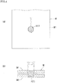
- FIGS. 2 to 6 show the respective laser beam emitting steps.
- the respective Figures (a) each show a plan view of the workpiece W and the scanning locus of the laser beam while the respective Figures (b) each show a cross-sectional view illustrating the joining region of the workpiece W and the laser beam (more specifically, each state in which the scanning position with the laser beam is moved at the rightmost position and at the leftmost position of the Figure).
- the laser welding according to this embodiment, five stages of emission of the laser beam (scanning with the laser beam) are performed (i.e. from the first laser beam emitting step to the fifth laser beam emitting step) such that a joining region having the desired outer diameter size is formed.
- the scanning locus (concentric circular scanning locus) to be scanned with the laser beam in this case has the diameter size that gradually increases from the first laser beam emitting step to the fifth laser beam emitting step in this order. Also, the outputs of the laser beam in the respective laser beam emitting steps have the same value.
- FIG. 7 is a graph indicating change in the output of the laser beam in the laser beam emitting steps.
- the period t1 indicates the period for the first laser beam emitting step
- the period t2 indicates the period for the second laser beam emitting step
- the period t3 indicates the period for the third laser beam emitting step
- the period t4 indicates the period for the fourth laser beam emitting step
- the period t5 indicates the period for the fifth laser beam emitting step.
- there is a period in which the output of the laser beam is zero, i.e. the emission interval between each adjacent two of the laser beam emitting steps.
- FIGS. 2 indicate the first laser beam emitting step (the laser beam emitting step performed for the first time).
- the scanning locus (the first scanning locus SC1) with the laser beam has the smallest diameter size (that is, the diameter size is smaller than the respective diameter sizes of the scanning loci SC2 to SC5 with the laser beam in the other laser beam emitting steps).
- the molten part of the metal material of the upper plate W1 and the lower plate W2 also has a small diameter size. In other words, the volume of the molten metal F is small.
- the laser beam is applied along the first scanning locus SC1 such that the laser beam is rotated (revolved) multiple times along the first scanning locus SC1.
- the number of rotations (the number of revolutions) of the laser beam is experimentally determined as a value to obtain the volume of the molten metal F to be bridged over the upper plate W1 and the lower plate W2.
- the upper plate W1 and the lower plate W2 are molten at the first scanning locus SC1 and in the vicinity thereof.
- a molten pool P is formed by the molten metal F.
- the molten metal F in the molten pool P is stirred and flowed. That is, the molten metal F is agitated within the molten pool P.
- the molten pool P is formed so as to have a cone shape due to the flow of the molten metal F in the circumferential direction.
- the molten metal F is undulated in the molten pool P.
- the molten pool P in which the molten metal F is undulated is aggregated due to the surface tension of the molten metal F, thus is formed as a joining part that does not have a hollow or a separated bead. In this way, the upper plate W1 and the lower plate W2 are integrally welded. As described above, since the molten metal F is undulated while flowing in the molten pool P due to the scanning with the laser beam, the molten pool P is sufficiently molten and stirred so that bubbles are satisfactorily discharged.
- the molten pool P is also undulated while flowing due to the scanning with the laser beam, the molten pool P is sufficiently stirred so that elements are sufficiently diffused to prevent segregation, and that the temperature is uniformized to reduce the heterogeneous state of the structure.
- FIGS. 3 indicate the second laser beam emitting step (the laser beam emitting step performed for the second time).
- the region indicated by the hatched lines is the joining region made by hardening the metal that has been molten in the first laser beam emitting step.
- the second laser beam emitting step is performed at the emission interval after termination of the first laser beam emitting step.
- the diameter size of the scanning locus with the laser beam in the second laser beam emitting step (the second scanning locus SC2) is larger than the diameter size of the first scanning locus SC1.
- the molten part of the metal material of the upper plate W1 and the lower plate W2 in the second laser beam emitting step also has a diameter size larger than the diameter size of the molten part of the metal material of the upper plate W1 and the lower plate W2 in the first laser beam emitting step.
- the laser beam is applied along the second scanning locus SC2 such that the laser beam is rotated (revolved) multiple times along the second scanning locus SC2.
- the number of rotations (the number of revolutions) of the laser beam is experimentally determined as a certain value to obtain the volume of the molten metal F to be newly bridged over the upper plate W1 and the lower plate W2.
- the upper plate W1 and the lower plate W2 are molten at the second scanning locus SC2 and in the vicinity thereof, similarly to the above-described first laser beam emitting step.
- the molten pool P is formed by the molten metal F.
- the molten metal F in the molten pool P is stirred and flowed. That is, the molten metal F is agitated within the molten pool P. Since the molten metal F is undulated while flowing in the molten pool P due to the scanning with the laser beam, bubbles are satisfactorily discharged from the molten pool P.
- elements are sufficiently diffused to prevent segregation, and the temperature is uniformized to reduce the heterogeneous state of the structure.
- FIGS. 4 indicate the third laser beam emitting step (the laser beam emitting step performed for the third time).
- FIGS. 5 indicate the fourth laser beam emitting step (the laser beam emitting step performed for the fourth time).
- FIGS. 6 indicate the fifth laser beam emitting step (the laser beam emitting step performed for the fifth (final) time).
- each region indicated by the hatched lines is the joining region made by hardening the metal that has been molten in the previous step.
- Each of these laser beam emitting steps is performed at the emission interval after termination of the previous step.
- the diameter size of the scanning locus to be scanned with the laser beam in each of these laser beam emitting steps is larger than the diameter size of the scanning locus in the previous step. Accordingly, the molten part of the metal material of the upper plate W1 and the lower plate W2 in each of the laser beam emitting steps also has a diameter size larger than the diameter size of the molten part of the metal material of the upper plate W1 and the lower plate W2 in the previous step.
- the laser beam is applied along the corresponding scanning locus to be scanned with the laser beam (specifically, the third scanning locus SC3, the fourth scanning locus SC4 and the fifth scanning locus SC5) such that the laser beam is rotated (revolved) multiple times along the corresponding scanning locus.
- the number of rotations (the number of revolutions) of the laser beam is experimentally determined as a certain value to obtain the volume of the molten metal F to be newly bridged over the upper plate W1 and the lower plate W2.
- the upper plate W1 and the lower plate W2 are molten at the respective scanning loci SC3, SC4 and SC5 and in the vicinities thereof, similarly to the above-described first laser beam emitting step.
- the molten pool P is formed by the molten metal F.
- the molten metal F in the molten pool P is stirred and flowed.
- bubbles are satisfactorily discharged from the molten pool P.
- elements are sufficiently diffused to prevent segregation, and the temperature is uniformized to reduce the heterogeneous state of the structure.
- Welding conditions for the respective laser beam emitting steps are specifically described.
- Examples of the welding conditions include: the diameter size of the scanning locus to be scanned with the laser beam; the scanning speed; the output of the laser beam; and the length of the emission interval. Note that specific values of the welding conditions are listed hereinafter as an example in which the upper plate W1 and the lower plate W2 both have a plate thickness of 1.0 mm and their plate gap is 0.8 mm.
- the diameter size of the scanning locus to be scanned with the laser beam is set such that the respective diameter sizes of the scanning loci SC1 to SC5 increase at regular intervals from the first laser beam emitting step to the fifth laser beam emitting step.
- the diameter size of the first scanning locus SC1 in the first laser beam emitting step is 0.4 mm
- the diameter size of the second scanning locus SC2 in the second laser beam emitting step is 0.8 mm
- the diameter size of the third scanning locus SC3 in the third laser beam emitting step is 1.2 mm
- the diameter size of the fourth scanning locus SC4 in the fourth laser beam emitting step is 1.6 mm
- the diameter size of the fifth scanning locus SC5 in the fifth laser beam emitting step is 2.0 mm.
- these values are not limited thereto.
- the scanning speed is the same through all of the first laser beam emitting step to the fifth laser beam emitting step.
- the scanning speed is set to 20 m/ min.
- this value also is not limited thereto.
- the respective laser beam emitting steps may have different scanning speeds.
- the output of the laser beam is the same through all of the first laser beam emitting step to the fifth laser beam emitting step, as described above.
- the output of the laser beam is set to 4,000 W. However, this value also is not limited thereto.
- the respective lengths of the emission intervals that are set between the laser beam emitting steps are the same.
- the length of the emission interval is set as a period of time that is needed to stabilize the cone-shaped molten pool P made of the metal molten in one laser beam emitting step after termination of this laser beam emitting step.
- the length of the emission interval is set to 0.05 sec. However, this value is not limited thereto.
- the first laser beam emitting step to the fifth laser beam emitting step are sequentially performed.
- the upper plate W1 and the lower plate W2 are integrally joined at the joining region.
- the laser beam emitting steps i.e. the first laser beam emitting step to the fifth laser beam emitting step with the emission interval being set between each adjacent two thereof
- the laser beam emitting steps are repeatedly performed. Accordingly, every time the scanning locus to be scanned with the laser beam is shifted, a period is provided to cool the metal that has been molten due to the previous irradiation with the laser beam.
- Such lowering of the temperature of the molten metal F increases its viscosity, which leads to reduction in the mass of the metal molten by irradiation with the laser beam after the scanning locus to be scanned with the laser beam is shifted (i.e. the mass of the molten metal F having the low viscosity is reduced).
- the subsequent irradiation with the laser beam i.e. application of the laser beam along the outer circular scanning locus
- the subsequent irradiation with the laser beam is performed after the temperature of the molten metal F has lowered.
- the joining regions were respectively made by welding two metal plates using the laser welding method according to the above-described embodiment and using the conventional laser welding method, so that the respective cross-sections of the joining regions were compared to each other.
- FIG. 8 is a cross-sectional view illustrating the joining region of the metal plates W1 and W2 as the experimental result when the two metal plates W1 and W2 were welded by the laser welding method according to this embodiment.
- FIG. 9 is a cross-sectional view illustrating the joining region of metal plates w1 and w2 as the experimental result when the two metal plates w1 and w2 were welded by the conventional laser welding method.
- the molten metal f was detached from the upper plate w1 to generate "burn through". In the part where the "burn through” was generated, the molten metal f was not bridged between the upper plate w1 and the lower plate w2, which means that the sufficient joining strength was not ensured.
- a region A i.e. a bridging part of the molten metal F/f to the upper plate W1/w1 in the Figures has a large cross-sectional area while a region B (i.e. a recess formed in the lower plate W2/w2; as the recess increases, the molten metal F/f is more thinned) has a small cross-sectional area.
- These cross-sectional areas were measured.
- the joining regions were respectively made by welding three metal plates using the laser welding method according to the above-described embodiment and using the conventional laser welding method, so that the respective cross-sections of the joining regions were compared to each other.
- FIG. 10 is a cross-sectional view illustrating the joining region of the metal plates W1, W2 and W3 as the experimental result when the three metal plates W1, W2 and W3 were welded by the laser welding method according to this embodiment.
- FIG. 11 is a cross-sectional view illustrating the joining region of metal plates w1, w2 and w3 as the experimental result when the three metal plates w1, w2 and w3 were welded by the conventional laser welding method.
- the molten metal f was detached from the upper plate w1 to generate "burn through". In the part where the "burn through” was generated, the molten metal f was not bridged between the upper plate w1 and the intermediate plate w3, which means that the sufficient joining strength was not ensured.
- the region A in the Figures has a large cross-sectional area while the region B has a small cross-sectional area. These cross-sectional areas were measured.
- the result showed that the cross-sectional area of the region A was approximately two times half the cross-sectional area of the region B.
- the result showed that the cross-sectional area of the region A was only about 90% of the cross-sectional area of the region B.
- Variation 1 is described.
- the output of the laser beam in the respective laser beam emitting steps is changed. Since the other configuration and the welding method are the same as those in the above-described embodiment, only the change in the output of the laser beam will be described hereinafter.
- FIG. 12 is a graph indicating the change in the output of the laser beam in the laser beam emitting steps in this Variation.
- the period t1 indicates the period for the first laser beam emitting step
- the period t2 indicates the period for the second laser beam emitting step
- the period t3 indicates the period for the third laser beam emitting step
- the period t4 indicates the period for the fourth laser beam emitting step
- the period t5 indicates the period for the fifth laser beam emitting step.
- the output of the laser beam is the same through all the first laser beam emitting step to the fifth laser beam emitting step (see FIG. 7 ).
- the output of the laser beam in the first laser beam emitting step is set larger than the output of the laser beam in the respective other laser beam emitting steps (i.e. from the second laser beam emitting step to the fifth laser beam emitting step). That is, the output of the laser beam that is applied to the innermost circular scanning locus in the joining region is set larger than the output of the laser beam that is applied to the respective other circular scanning loci.
- the relationship between the output of the laser beam in the first laser beam emitting step and the output of the laser beam in the respective other laser beam emitting steps is set based on experiments and/or simulations.
- the output of the laser beam in the first laser beam emitting step is set to 20% higher than the output of the laser beam in the respective other laser beam emitting steps.
- the above value is not limited thereto.
- the metal material of the joining region has not at all been molten yet.
- the metal material requires a large heat input in order to be molten compared to the case in which the laser beam is applied to any of the other scanning loci SC2 to SC5 (i.e. the case in which the metal material has already been molten at the inner circular scanning locus).
- the output of the laser beam applied to the innermost first scanning locus SC1 is set larger than the output of the laser beam applied to any of the other scanning loci SC2 to SC5, so that the metal material in the vicinity of the first scanning locus SC1 is effectively molten and the time required to perform the laser welding is shorten.
- Variation 2 is described. In this Variation also, the output of the laser beam in the respective laser beam emitting steps is changed. Since the other configuration and the welding method are the same as those in the above-described embodiment, only the change in the output of the laser beam will be described hereinafter.
- FIG. 13 is a graph indicating the change in the output of the laser beam in the laser beam emitting steps in this Variation.
- the period t1 indicates the period for the first laser beam emitting step
- the period t2 indicates the period for the second laser beam emitting step
- the period t3 indicates the period for the third laser beam emitting step
- the period t4 indicates the period for the fourth laser beam emitting step
- the period t5 indicates the period for the fifth laser beam emitting step.
- every length of the emission interval between the adjacent two steps of the first laser beam emitting step to the fifth laser beam emitting step is the same (see FIG. 7 ).
- the length of the emission interval becomes longer as the laser beam emitting steps proceed. That is, the length of the emission interval is set longer as the circular scanning locus to be scanned with the laser beam is shifted to the outer one.
- the ratio of the respective lengths of the emission intervals is set based on experiments and/or simulations. As one example, the length of the emission interval is set to 20% longer every time the scanning locus to be scanned with the laser beam is shifted. However, the above value is not limited thereto.
- the subsequent irradiation with the laser beam i.e. application of the laser beam along the outer circular scanning locus
- the subsequent irradiation with the laser beam is performed before the molten metal F has completely hardened, even when the emission interval is provided.
- the subsequent irradiation with the laser beam is performed on the metal plates W1 and W2 in which heat is stored.
- the amount of heat stored in the metal plates has a tendency to increase as the irradiation with the laser beam is shifted between the adjacent two of the circular scanning loci on the outer side.
- the length of the emission interval is set longer as the circular scanning locus to be scanned with the laser beam is shifted to the outer one, so that hardening of the molten metal F is accelerated (in other words, the viscosity is reduced). Therefore, the "burn through" of the molten metal F is reliably prevented.
- Variation 3 is described.
- the irradiation on the joining region with the laser beam differs from that in the above-described embodiment. Since the other configuration and the welding method are the same as those in the above-described embodiment, only the aspect of the irradiation with the laser beam will be described hereinafter.
- the laser welding method is constituted of only the five steps, namely, the first laser beam emitting step to the fifth laser beam emitting step.
- an initial laser beam emitting step is performed as a step previous to the first laser beam emitting step, in which the laser beam is applied to one point of the central part of the joining region. That is, the position irradiated with the laser beam is fixed as one point that is not moved to make a scanning locus, thus only the central part of the joining region of the metal plates W1 and W2 is molten.
- the output of the laser beam in this initial laser beam emitting step is set higher than the output of the laser beam in the respective other laser beam emitting steps (i.e. the first laser beam emitting step to the fifth laser beam emitting step).
- the relationship between the output of the laser beam in the initial laser beam emitting step and the output of the laser beam in the respective other laser beam emitting steps is set based on experiments and/or simulations.
- the output of the laser beam in the initial laser beam emitting step is set to 20% higher than the output of the laser beam in the respective other laser beam emitting steps.
- the above value is not limited thereto.
- the metal material of the joining region has not at all been molten yet.
- the metal material requires a large heat input in order to be molten.
- the output of the laser beam applied to the one point of the central part of the joining region is set larger than the output of the laser beam applied to any of the circular scanning loci, so that the metal material in the central part of the joining region is effectively molten and the time required to perform the laser welding is shorten.
- Variation 4 is described.
- the joining regions made by the laser welding method according to the above-described embodiment are disposed respectively at positions adjacent to one another.
- FIG. 14(a) is a plan view illustrating the workpiece W having two joining regions adjacent to each other.
- FIG. 14(b) is a plan view illustrating the workpiece W having three joining regions adjacent to one another. In both cases, the laser welding method similar to the method in the above-described embodiment is applied to the respective joining regions.
- any of the laser welding methods according to the above Variations may be applied to the respective joining regions.
- the description was given on the case in which the present invention was applied as a laser welding method performed by the laser welding apparatus 1 in the vehicle body manufacturing process.
- the present invention can be applied to the laser welding for other members.
- the present invention is not limited thereto. It may be applied as a laser welding method for welding three or more plate materials to one another.
- the plate material to which is applicable the laser welding method of the present invention is not limited to aluminum. It may be made of iron, magnesium, titanium or copper.
- the present invention can be applied to the welding of dissimilar metals.
- the workpiece W was irradiated with the laser beam from the above.
- the present invention is not limited thereto. It may be applied to the lap welding of the metal plates superimposed on each other in the horizontal direction. That is, the present invention can be applied to the case in which the laser beam is applied to the workpiece in the horizontal direction.
- the laser beam emitting steps are constituted of the five steps from the first laser beam emitting step to the fifth laser beam emitting step.
- the laser beam emitting steps may be constituted of four or less laser beam emitting steps, or may be constituted of six or more laser beam emitting steps.
- the present invention is suitably applicable to a laser welding method in which a lap welding with the laser beam is performed to aluminum metal plates.
Landscapes
- Physics & Mathematics (AREA)
- Optics & Photonics (AREA)
- Engineering & Computer Science (AREA)
- Plasma & Fusion (AREA)
- Mechanical Engineering (AREA)
- Laser Beam Processing (AREA)
Abstract
Description
- The present invention relates to a laser welding method for joining a plurality of metal plates superimposed on each other. Particularly, the present invention relates to improvement of an irradiation mode on a metal plate with a laser beam.
- Conventionally, laser welding is known as a method for joining (welding) a plurality of metal plates superimposed on each other.
Patent Document 1 discloses a method for welding two metal plates superimposed on each other, which includes the steps of: irradiating a surface of the metal plates with a laser beam; melting the metal plates to form a molten pool; and irradiating the molten pool with the laser beam to flow molten metal in the molten pool. Thus, the joining strength between the metal plates is ensured. - Patent Document 1:
JP 2012-228715 A - However, when a gap formed between the metal plates (i.e. a plate gap) is large, it is necessary to increase the amount of molten metal in order to make the molten metal bridge the gap over the respective metal plates. In this case, a welding defect called as "burn through" may be generated. That is, the molten metal of the metal plate irradiated with the laser beam (i.e. an upper plate when the metal plates are superimposed on each other in the vertical direction) may fall toward the other metal plate (i.e. a lower plate when the metal plates are superimposed on each other in the vertical direction). In particular, when an area of the joining region (i.e. an area of the molten metal that hardens in plan view of the metal plate) on the metal plate is increased in order to ensure a sufficient joining strength between the metal plates, a larger amount of molten metal is needed. Accordingly, the "burn through" is likely to occur, which results in an insufficient joining strength.
-
FIGS. 15 are diagrams illustrating a state of metal plates having an increased joining region during irradiation with the laser beam in the conventional laser welding.FIG. 15(a) is a cross-sectional view of the joining region of the metal plates and the laser beam.FIG. 15(b) is a plan view of the metal plates. InFIGS. 15 , the laser welding is performed in a state in which the gap formed between the metal plates (an upper plate a and a lower plate b) is large, where the laser beam is indicated by the dashed dotted line. A molten metal c of the upper plate a hangs down toward the lower plate b. When the irradiation with the laser beam is continued under the circumstances, the molten metal c may be detached from the upper plate a to generate the "burn through", as shown inFIGS. 16 (diagrams illustrating a state in which the irradiation with the laser beam is completed, which respectively correspond to the diagrams ofFIGS. 15 ). That is, inFIGS. 16 , the molten metal c is not bridged between the upper plate a and the lower plate b at the part enclosed by the circle indicated by the dashed double-dotted line, which means that a sufficient joining strength cannot be ensured. - As described above, in the conventional art, it is difficult to sufficiently obtain the joining strength between the metal plates by increasing the area of the joining region while preventing the "burn through" of the molten metal.
- The present invention was made in consideration of the above problem, an object of which is to provide a laser welding method capable of ensuring a sufficient joining strength between metal plates by increasing an area of a joining region while preventing the "burn through" of a molten metal.
- As a means for solving the above problem to achieve the object of the present invention, a laser welding method for joining metal plates is provided, which includes the steps of: applying a laser beam to a surface of a plurality of metal plates superimposed on each other; melting the metal plates by scanning a position to be irradiated so as to make a molten pool constituted of the molten metal; stirring the molten pool by scanning with the laser beam; shifting sequentially a scanning locus to be scanned with the laser beam from an inner circular scanning locus to an outer circular scanning locus in a predetermined joining region on the metal plates; and providing an emission interval at the time of shifting the scanning locus to be scanned with the laser beam so that the irradiation on the surface of the metal plates with the laser beam is temporally stopped.
- With the above-described configuration, when a plurality of metal plates superimposed on each other is joined by laser welding, the scanning with the laser beam (applying the laser beam) is performed along the inner circular scanning locus in the predetermined joining region on the metal plates so as to melt the metal (metal material) in the vicinity of the scanning locus. A molten pool constituted of the molten metal is scanned and stirred with the laser beam. After that, the irradiation on the surface of the metal plates with the laser beam is temporally stopped when the scanning locus to be scanned with the laser beam is shifted to the outer circular scanning locus. In other words, after a certain emission interval (i.e. period for which the irradiation on the surface of the metal plates with the laser beam is temporally stopped) elapses, the scanning with the laser beam (applying the laser beam) is re-started along the outer circular scanning locus so as to melt the metal material in the vicinity of the outer circular scanning locus. A molten pool constituted of the molten metal is scanned and stirred with the laser beam. By repeatedly preforming the above procedures, every time the scanning locus to be scanned with the laser beam is shifted, a period is provided to cool the metal that has been molten due to the previous irradiation with the laser beam. Such lowering of the temperature of the molten metal increases its viscosity, which leads to reduction in the mass of the metal molten by irradiation with the laser beam after the scanning locus to be scanned with the laser beam is shifted (i.e. the mass of the molten metal having the low viscosity is reduced). As a result, it is possible to prevent generation of "burn through" of the molten metal. That is, the "burn through" can be reduced even when the area of the joining region is increased. Therefore, it is possible to ensure the sufficient joining strength between the metal plates by increasing the area of the joining region while preventing the "burn through" of the molten metal.
- It is preferable that the circular scanning loci are concentric circles centered at a central part of the joining region.
- In this case, the scanning with the laser beam is successively performed along the respective concentric circular scanning loci, and the irradiation on the surface of the metal plates with the laser beam is temporally stopped at the time of shifting the scanning locus. In this way, it is possible to realize the circular joining region having a large area while preventing the "burn through" of the molten metal.
- When each of all the emissions of the laser beam is performed along the corresponding circular scanning locus at the emission interval, it is preferable that the output of the laser beam that is applied to the innermost circular scanning locus in the joining region is set larger than the output of the laser beam that is applied to any of the other circular scanning loci.
- In the case where each of all the emissions of the laser beam is performed along the corresponding circular scanning locus at the emission interval, when the laser beam is applied to the innermost circular scanning locus in the joining region, the metal material of the joining region has not at all been molten yet. Thus, the metal material requires a large heat input in order to be molten compared to the case in which the laser beam is applied to any of the other scanning loci (i.e. the case in which the metal material has already been molten at the inner circular scanning locus). Taking into account the above circumstances, in this means for solving the problem, the output of the laser beam applied to the innermost circular scanning locus is set larger than the output of the laser beam applied to any of the other circular scanning loci, so that the metal material in the vicinity of the innermost circular scanning locus is effectively molten and the time required to perform the laser welding is shorten.
- Also, when the laser beam is applied to one point of the central part of the joining region before application of the laser beam to the innermost circular scanning locus in the joining region, it is preferable that the output of the laser beam applied to the one point of the central part is set larger than the output of the laser beam that is applied to any of the other circular scanning loci.
- In the case where the laser beam is applied to one point of the central part of the joining region before application of the laser beam to the innermost circular scanning locus in the joining region, when the laser beam is applied to the one point of the central part of the joining region, the metal material of the joining region has not at all been molten yet. Thus, the metal material requires a large heat input in order to be molten. Taking into account the above circumstances, in this means for solving the problem, the output of the laser beam applied to the one point of the central part of the joining region is set larger than the output of the laser beam applied to the circular scanning loci, so that the metal material in the central part of the joining region is effectively molten and the time required to perform the laser welding is shorten.
- It is preferable that the length of the emission interval is set longer as the circular scanning locus to be scanned with the laser beam is shifted to the outer circular scanning locus.
- When the scanning locus to be scanned with the laser beam is sequentially shifted from the inner circular scanning locus to the outer circular scanning locus in the joining region, the subsequent irradiation with the laser beam (i.e. application of the laser beam along the outer circular scanning locus) is performed before the molten metal has completely hardened, even when the emission interval is provided. In other words, the subsequent irradiation with the laser beam is performed on the metal plates in which heat is stored. The amount of heat stored in the metal plates has a tendency to increase as the irradiation with the laser beam is shifted between the adjacent two of the circular scanning loci on the outer side. Taking into account the above circumstances, in this means for solving the problem, the length of the emission interval is set longer as the circular scanning locus to be scanned with the laser beam is shifted to the outer one, so that hardening of the molten metal is accelerated (in other words, the viscosity is reduced). Therefore, the "burn through" of the molten metal is reliably prevented.
- In the laser welding in which the laser beam is applied to a surface of a plurality of metal plates superimposed on each other of the present invention, the scanning locus to be scanned with the laser beam is sequentially shifted from an inner circular scanning locus to an outer circular scanning locus in a predetermined joining region on the metal plates, and an emission interval is provided at the time of shifting the scanning locus to be scanned with the laser beam so that the irradiation on the surface of the metal plates with the laser beam is temporally stopped. In this way, every time the scanning locus to be scanned with the laser beam is shifted, a period is provided to cool the metal that has been molten due to the previous irradiation with the laser beam, and such lowering of the temperature of the molten metal increases its viscosity. As a result, the "burn through" of the molten metal can be reduced even when the area of the joining region is increased. Therefore, it is possible to ensure the sufficient joining strength between the metal plates.
-
-
FIG. 1 is a schematic configuration diagram illustrating a laser welding apparatus used for laser welding according to an embodiment. -
FIGS. 2 are diagrams illustrating a first laser beam emitting step.FIG. 2(a) is a plan view illustrating a metal plate and a scanning locus of the laser beam.FIG. 2(b) is a cross-sectional view illustrating a joining region between metal plates and the laser beam. -
FIGS. 3 are diagrams respectively corresponding toFIGS. 2 in a second laser beam emitting step. -
FIGS. 4 are diagrams respectively corresponding toFIGS. 2 in a third laser beam emitting step. -
FIGS. 5 are diagrams respectively corresponding toFIGS. 2 in a fourth laser beam emitting step. -
FIGS. 6 are diagrams respectively corresponding toFIGS. 2 in a fifth laser beam emitting step. -
FIG. 7 is a graph indicating change in laser output in the laser beam emitting steps. -
FIG. 8 is a cross-sectional view illustrating the joining region of the metal plates as an experimental result when two metal plates are welded by the laser welding method according to the embodiment. -
FIG. 9 is a cross-sectional view illustrating the joining region of the metal plates as an experimental result when two metal plates are welded by the conventional laser welding method. -
FIG. 10 is a cross-sectional view illustrating the joining region of the metal plates as an experimental result when three metal plates are welded by the laser welding method according to the embodiment. -
FIG. 11 is a cross-sectional view illustrating the joining region of the metal plates as an experimental result when three metal plates are welded by the conventional laser welding method. -
FIG. 12 is a graph indicating change in laser output in the laser beam emitting steps inVariation 1. -
FIG. 13 is a graph indicating change in laser output in the laser beam emitting steps inVariation 2. -
FIGS. 14 are plan views illustrating the metal plate having a plurality of joining regions.FIG. 14(a) is a plan view illustrating the metal plate having two joining regions adjacent to each other.FIG. 14(b) is a plan view illustrating the metal plate having three joining regions adjacent to one another. -
FIGS. 15 are diagrams illustrating a state of the metal plates during irradiation with the laser beam in the conventional art.FIG. 15(a) is a cross-sectional view illustrating the joining region of the metal plates and the laser beam.FIG. 15(b) is a plan view illustrating the metal plate. -
FIGS. 16 are diagrams respectively corresponding toFIGS. 15 , which illustrate a state in which the irradiation with the laser beam is completed in the conventional art. - Hereinafter, an embodiment of the present invention will be described with reference to the drawings. In this embodiment, a description will be given on a case in which the present invention is applied as a laser welding method that is performed by a laser welding apparatus used in a manufacturing process of vehicles bodies.
-
FIG. 1 is a schematic configuration diagram illustrating alaser welding apparatus 1 used for laser welding according to this embodiment. As shown inFIG. 1 , thelaser welding apparatus 1 includes alaser oscillator 2, alaser scanner 3, a welding robot 4 and arobot controller 5. - The
laser oscillator 2 generates a laser beam. The generated laser beam is guided to thelaser scanner 3 via anoptical fiber cable 21. It is possible to use the laser beam such as a carbon dioxide laser, a YAG laser, or a fiber laser. - The
laser scanner 3 irradiates a workpiece W, which is formed by superimposing two plate materials made of aluminum alloy (aluminum metal plates, hereinafter occasionally referred to as simply "metal plates") W1 and W2 on each other, with the laser beam guided via the optical fiber cable 21 (see the dashed dotted line inFIG. 1 ). In thelaser scanner 3, a plurality of lenses (not shown) and a plurality of mirrors 31 (inFIG. 1 , only onemirror 31 is shown) are housed. As the lenses, thelaser scanner 3 includes, for example, a collimating lens to convert the laser beam into a parallel beam and a condensing lens to converge the laser beam such that the converged laser beam is focused on a machining point of the workpiece W (i.e. on a predetermined position irradiated with the laser beam on the workpiece W). Also, eachmirror 31 is rotatable about arotary shaft 32. Specifically, therotary shaft 32 is coupled to ascanning motor 33, and thescanning motor 33 is activated to rotate therotary shaft 32 that causes themirror 31 to rotate. Then, the workpiece W is scanned with the laser beam by the rotation of themirror 31, and thus the position irradiated with the laser beam can be changed within the predetermined area on the workpiece W. In this way, it is possible to change the position irradiated with the laser beam without moving thelaser scanner 3 itself. Each of themirrors 31 may, for example, be constituted of a galvanometer mirror. - The laser welding according to this embodiment is a so-called laser screw welding (LSW). That is, a welding part (a joining region) of the workpiece W is scanned with the laser beam along a predetermined scanning locus so that the welding part is molten to be welded. The scanning with the laser beam is performed by the
mirrors 31. The scanning with the laser beam will be described in detail later. - The welding robot 4 is configured to cause the
laser scanner 3 to move. The welding robot 4 is constituted of an articulated robot. Specifically, the welding robot 4 of this embodiment includes: a base 41; a rotation mechanism (not shown) housed in thebase 41;joints arms laser scanner 3 can be moved in a desired direction by rotating motions of the rotation mechanism and swinging motions of thearms joints - Information for moving the
laser scanner 3 toward a part to be welded (for example, information on respective amounts of rotation angles at thejoints robot controller 5 by off-line teaching previously performed. When a vehicle body is conveyed to the welding work station on the vehicle body manufacturing line, the welding robot 4 operates based on the above information in response to a control signal from therobot controller 5. Thus, thelaser scanner 3 is faced to the part to be welded so that the laser beam is emitted from thelaser scanner 3 to the part to be welded. In this way, the laser welding is sequentially performed. - Also, the
robot controller 5 includes a laserscanning control unit 51 to output a control signal to change the position to be irradiated with the laser beam on the workpiece W. The laserscanning control unit 51 outputs the control signal to thescanning motor 33. Thescanning motor 33 operates in response to the control signal so as to perform the scanning with the laser beam by rotation of therespective mirrors 31 about therotary shafts 32. Thus, the position to be irradiated with the laser beam on the workpiece W is moved. The movement of the position to be irradiated with the laser beam (i.e. the scanning) on the workpiece W will be described later. - Here, a welding method (laser welding method) as a characteristic feature of this embodiment is described. In this embodiment, a description is given on the case in which two metal plates W1 and W2 superimposed on each other in the vertical direction are subjected to a lap welding. In particular, the superimposed part of the metal plates W1 and W2 is irradiated, from the above, with the laser beam emitted by the
laser scanner 3. Hereinafter, the upper metal plate is referred to as an upper plate W1 while the lower metal plate is referred to as a lower plate W2. - The laser welding according to this embodiment is performed by scanning a joining region previously determined on the upper plate W1 with the laser beam. Specifically, a plurality of (in this embodiment, five) concentric circle shaped scanning loci (annular scanning loci; i.e. circular scanning loci in the present invention) centered at a central part of the joining region is previously determined. Then, the scanning locus to be scanned with the laser beam is sequentially shifted from the inner circular scanning locus to the outer circular scanning locus out of the circular scanning loci. The joining region is set as a circular region having a predetermined outer diameter size. The outer diameter size is previously determined as a size to obtain a desirable joining strength between the metal plates W1 and W2, taking into account, for example, the rigidity of a vehicle.
- The respective circular scanning loci are five concentric circles centered at the central part of the joining region. The scanning with the laser beam is performed sequentially from a first scanning locus SC1 defined as the innermost locus (see
FIGS. 2 ) to a fifth scanning locus SC5 defined as the outermost locus (seeFIGS. 6 ). When the scanning locus to be scanned with the laser beam is shifted, an emission interval is provided so as to temporally stop the emission of the laser beam to the surface of the upper plate W1. By providing this emission interval, a period for cooling the metal that has been molten due to irradiation with the laser beam can be ensured, which results in a high viscosity of the molten metal due to lowering of the temperature thereof. Also by providing the emission interval, the subsequent emission of the laser beam is performed (i.e. the laser beam is applied along the outer circular scanning locus) after the temperature of the molten metal has decreased. Thus, it is possible to reduce the heat input per unit volume to the molten metal and to reduce spatter (i.e. scattering of the molten metal). As a result, it is possible to prevent thinning of the molten metal that is bridged over the upper plate W1 and the lower plate W2. - As an example of operations to temporally stop the emission of the laser beam to the surface of the upper plate W1, the output of the laser beam from the
laser oscillator 2 can be temporally stopped. Also, the focal position of the laser beam that is applied along each scanning locus SC1 to SC5 may be a position where the laser beam penetrates the upper plate W1 or a position where the laser beam does not penetrate the upper plate W1 (i.e. a position on the surface of the upper plate W1). - Hereinafter, the laser beam emitting steps will be specifically described.
FIGS. 2 to 6 show the respective laser beam emitting steps. Among them, the respective Figures (a) each show a plan view of the workpiece W and the scanning locus of the laser beam while the respective Figures (b) each show a cross-sectional view illustrating the joining region of the workpiece W and the laser beam (more specifically, each state in which the scanning position with the laser beam is moved at the rightmost position and at the leftmost position of the Figure). - As shown in these Figures, in the laser welding according to this embodiment, five stages of emission of the laser beam (scanning with the laser beam) are performed (i.e. from the first laser beam emitting step to the fifth laser beam emitting step) such that a joining region having the desired outer diameter size is formed.
- The scanning locus (concentric circular scanning locus) to be scanned with the laser beam in this case has the diameter size that gradually increases from the first laser beam emitting step to the fifth laser beam emitting step in this order. Also, the outputs of the laser beam in the respective laser beam emitting steps have the same value.
FIG. 7 is a graph indicating change in the output of the laser beam in the laser beam emitting steps. InFIG. 7 , the period t1 indicates the period for the first laser beam emitting step, the period t2 indicates the period for the second laser beam emitting step, the period t3 indicates the period for the third laser beam emitting step, the period t4 indicates the period for the fourth laser beam emitting step, and the period t5 indicates the period for the fifth laser beam emitting step. As shown inFIG. 7 , there is a period in which the output of the laser beam is zero, i.e. the emission interval between each adjacent two of the laser beam emitting steps. - Hereinafter, the respective laser beam emitting steps are described.
-
FIGS. 2 indicate the first laser beam emitting step (the laser beam emitting step performed for the first time). In the first laser beam emitting step, the scanning locus (the first scanning locus SC1) with the laser beam has the smallest diameter size (that is, the diameter size is smaller than the respective diameter sizes of the scanning loci SC2 to SC5 with the laser beam in the other laser beam emitting steps). Accordingly, the molten part of the metal material of the upper plate W1 and the lower plate W2 also has a small diameter size. In other words, the volume of the molten metal F is small. In the first laser beam emitting step, the laser beam is applied along the first scanning locus SC1 such that the laser beam is rotated (revolved) multiple times along the first scanning locus SC1. The number of rotations (the number of revolutions) of the laser beam is experimentally determined as a value to obtain the volume of the molten metal F to be bridged over the upper plate W1 and the lower plate W2. - In the first laser beam emitting step in which the laser beam is rotated multiple times along the first scanning locus SC1, the upper plate W1 and the lower plate W2 are molten at the first scanning locus SC1 and in the vicinity thereof. Thus, a molten pool P is formed by the molten metal F. By the scanning with the laser beam, the molten metal F in the molten pool P is stirred and flowed. That is, the molten metal F is agitated within the molten pool P. In this case, the molten pool P is formed so as to have a cone shape due to the flow of the molten metal F in the circumferential direction. At the same time, the molten metal F is undulated in the molten pool P. The molten pool P in which the molten metal F is undulated is aggregated due to the surface tension of the molten metal F, thus is formed as a joining part that does not have a hollow or a separated bead. In this way, the upper plate W1 and the lower plate W2 are integrally welded. As described above, since the molten metal F is undulated while flowing in the molten pool P due to the scanning with the laser beam, the molten pool P is sufficiently molten and stirred so that bubbles are satisfactorily discharged. Since the molten pool P is also undulated while flowing due to the scanning with the laser beam, the molten pool P is sufficiently stirred so that elements are sufficiently diffused to prevent segregation, and that the temperature is uniformized to reduce the heterogeneous state of the structure.
-
FIGS. 3 indicate the second laser beam emitting step (the laser beam emitting step performed for the second time). InFIGS. 3 , the region indicated by the hatched lines is the joining region made by hardening the metal that has been molten in the first laser beam emitting step. The second laser beam emitting step is performed at the emission interval after termination of the first laser beam emitting step. The diameter size of the scanning locus with the laser beam in the second laser beam emitting step (the second scanning locus SC2) is larger than the diameter size of the first scanning locus SC1. Accordingly, the molten part of the metal material of the upper plate W1 and the lower plate W2 in the second laser beam emitting step also has a diameter size larger than the diameter size of the molten part of the metal material of the upper plate W1 and the lower plate W2 in the first laser beam emitting step. In the second laser beam emitting step, the laser beam is applied along the second scanning locus SC2 such that the laser beam is rotated (revolved) multiple times along the second scanning locus SC2. The number of rotations (the number of revolutions) of the laser beam is experimentally determined as a certain value to obtain the volume of the molten metal F to be newly bridged over the upper plate W1 and the lower plate W2. - In the second laser beam emitting step, the upper plate W1 and the lower plate W2 are molten at the second scanning locus SC2 and in the vicinity thereof, similarly to the above-described first laser beam emitting step. Thus, the molten pool P is formed by the molten metal F. By the scanning with the laser beam, the molten metal F in the molten pool P is stirred and flowed. That is, the molten metal F is agitated within the molten pool P. Since the molten metal F is undulated while flowing in the molten pool P due to the scanning with the laser beam, bubbles are satisfactorily discharged from the molten pool P. Also in the molten pool P, elements are sufficiently diffused to prevent segregation, and the temperature is uniformized to reduce the heterogeneous state of the structure.
-
FIGS. 4 indicate the third laser beam emitting step (the laser beam emitting step performed for the third time).FIGS. 5 indicate the fourth laser beam emitting step (the laser beam emitting step performed for the fourth time).FIGS. 6 indicate the fifth laser beam emitting step (the laser beam emitting step performed for the fifth (final) time). In these Figures also, each region indicated by the hatched lines is the joining region made by hardening the metal that has been molten in the previous step. Each of these laser beam emitting steps is performed at the emission interval after termination of the previous step. The diameter size of the scanning locus to be scanned with the laser beam in each of these laser beam emitting steps (specifically, the third scanning locus SC3, the fourth scanning locus SC4 and the fifth scanning locus SC5) is larger than the diameter size of the scanning locus in the previous step. Accordingly, the molten part of the metal material of the upper plate W1 and the lower plate W2 in each of the laser beam emitting steps also has a diameter size larger than the diameter size of the molten part of the metal material of the upper plate W1 and the lower plate W2 in the previous step. In each of these laser beam emitting steps, the laser beam is applied along the corresponding scanning locus to be scanned with the laser beam (specifically, the third scanning locus SC3, the fourth scanning locus SC4 and the fifth scanning locus SC5) such that the laser beam is rotated (revolved) multiple times along the corresponding scanning locus. The number of rotations (the number of revolutions) of the laser beam is experimentally determined as a certain value to obtain the volume of the molten metal F to be newly bridged over the upper plate W1 and the lower plate W2. - In the respective steps from the third laser beam emitting step to the fifth laser beam emitting step also, the upper plate W1 and the lower plate W2 are molten at the respective scanning loci SC3, SC4 and SC5 and in the vicinities thereof, similarly to the above-described first laser beam emitting step. Thus, the molten pool P is formed by the molten metal F. By the scanning with the laser beam, the molten metal F in the molten pool P is stirred and flowed. Thus, bubbles are satisfactorily discharged from the molten pool P. Also in the molten pool P, elements are sufficiently diffused to prevent segregation, and the temperature is uniformized to reduce the heterogeneous state of the structure.
- Welding conditions for the respective laser beam emitting steps are specifically described. Examples of the welding conditions include: the diameter size of the scanning locus to be scanned with the laser beam; the scanning speed; the output of the laser beam; and the length of the emission interval. Note that specific values of the welding conditions are listed hereinafter as an example in which the upper plate W1 and the lower plate W2 both have a plate thickness of 1.0 mm and their plate gap is 0.8 mm.
- In this embodiment, the diameter size of the scanning locus to be scanned with the laser beam is set such that the respective diameter sizes of the scanning loci SC1 to SC5 increase at regular intervals from the first laser beam emitting step to the fifth laser beam emitting step. For example, the diameter size of the first scanning locus SC1 in the first laser beam emitting step is 0.4 mm, the diameter size of the second scanning locus SC2 in the second laser beam emitting step is 0.8 mm, the diameter size of the third scanning locus SC3 in the third laser beam emitting step is 1.2 mm, the diameter size of the fourth scanning locus SC4 in the fourth laser beam emitting step is 1.6 mm, and the diameter size of the fifth scanning locus SC5 in the fifth laser beam emitting step is 2.0 mm. However, these values are not limited thereto.
- Also, the scanning speed is the same through all of the first laser beam emitting step to the fifth laser beam emitting step. For example, the scanning speed is set to 20 m/ min. However, this value also is not limited thereto. Furthermore, the respective laser beam emitting steps may have different scanning speeds.
- Also, the output of the laser beam is the same through all of the first laser beam emitting step to the fifth laser beam emitting step, as described above. For example, the output of the laser beam is set to 4,000 W. However, this value also is not limited thereto.
- Also, the respective lengths of the emission intervals that are set between the laser beam emitting steps are the same. The length of the emission interval is set as a period of time that is needed to stabilize the cone-shaped molten pool P made of the metal molten in one laser beam emitting step after termination of this laser beam emitting step. For example, the length of the emission interval is set to 0.05 sec. However, this value is not limited thereto.
- Under the welding conditions set as described above, the first laser beam emitting step to the fifth laser beam emitting step are sequentially performed. Thus, the upper plate W1 and the lower plate W2 are integrally joined at the joining region.
- As described above, in this embodiment, the laser beam emitting steps (i.e. the first laser beam emitting step to the fifth laser beam emitting step with the emission interval being set between each adjacent two thereof) are repeatedly performed. Accordingly, every time the scanning locus to be scanned with the laser beam is shifted, a period is provided to cool the metal that has been molten due to the previous irradiation with the laser beam. Such lowering of the temperature of the molten metal F increases its viscosity, which leads to reduction in the mass of the metal molten by irradiation with the laser beam after the scanning locus to be scanned with the laser beam is shifted (i.e. the mass of the molten metal F having the low viscosity is reduced). As a result, it is possible to prevent generation of the welding defect such as "burn through" in which the molten metal F is detached from the upper plate W1. That is, the "burn through" can be reduced even when the area of the joining region is increased. Therefore, it is possible to ensure the sufficient joining strength between the metal plates W1 and W2 by increasing the area of the joining region while preventing the "burn through" of the molten metal F.
- Also, by providing the emission interval, the subsequent irradiation with the laser beam (i.e. application of the laser beam along the outer circular scanning locus) is performed after the temperature of the molten metal F has lowered. Thus, it is possible to reduce the heat input per unit volume to the molten metal F and to reduce spatter. As a result, it is possible to prevent thinning of the molten metal F that is bridged over the upper plate W1 and the lower plate W2. In this way also, it is possible to prevent detaching of the molten metal F from the upper plate W1 and to ensure the sufficient joining strength between the upper plate W1 and the lower plate W2.
- Here, a description will be given on examples conducted in order to confirm the above-described effects.
- As a first Example, the joining regions were respectively made by welding two metal plates using the laser welding method according to the above-described embodiment and using the conventional laser welding method, so that the respective cross-sections of the joining regions were compared to each other.
-
FIG. 8 is a cross-sectional view illustrating the joining region of the metal plates W1 and W2 as the experimental result when the two metal plates W1 and W2 were welded by the laser welding method according to this embodiment.FIG. 9 is a cross-sectional view illustrating the joining region of metal plates w1 and w2 as the experimental result when the two metal plates w1 and w2 were welded by the conventional laser welding method. - In the joining region made by the conventional laser welding method as shown in
FIG. 9 , the molten metal f was detached from the upper plate w1 to generate "burn through". In the part where the "burn through" was generated, the molten metal f was not bridged between the upper plate w1 and the lower plate w2, which means that the sufficient joining strength was not ensured. - In contrast to the above, in the joining region made by the laser welding method according to this embodiment as shown in
FIG. 8 , no "burn through" was generated, and the molten metal F was bridged between the upper plate W1 and the lower plate W2 over the entire joining region, which means that the sufficient joining strength was ensured. - Especially, in order to obtain the above-described effects, it is preferable that a region A (i.e. a bridging part of the molten metal F/f to the upper plate W1/w1) in the Figures has a large cross-sectional area while a region B (i.e. a recess formed in the lower plate W2/w2; as the recess increases, the molten metal F/f is more thinned) has a small cross-sectional area. These cross-sectional areas were measured. When the laser welding method of this embodiment was applied, the result showed that the cross-sectional area of the region A was approximately two times the cross-sectional area of the region B. In contrast, when the conventional laser welding method was applied, the result showed that the cross-sectional area of the region A was only about 90% of the cross-sectional area of the region B.
- As a second Example, the joining regions were respectively made by welding three metal plates using the laser welding method according to the above-described embodiment and using the conventional laser welding method, so that the respective cross-sections of the joining regions were compared to each other.
-
FIG. 10 is a cross-sectional view illustrating the joining region of the metal plates W1, W2 and W3 as the experimental result when the three metal plates W1, W2 and W3 were welded by the laser welding method according to this embodiment.FIG. 11 is a cross-sectional view illustrating the joining region of metal plates w1, w2 and w3 as the experimental result when the three metal plates w1, w2 and w3 were welded by the conventional laser welding method. - In the joining region made by the conventional laser welding method as shown in
FIG. 11 , the molten metal f was detached from the upper plate w1 to generate "burn through". In the part where the "burn through" was generated, the molten metal f was not bridged between the upper plate w1 and the intermediate plate w3, which means that the sufficient joining strength was not ensured. - In contrast to the above, in the joining region made by the laser welding method according to this embodiment as shown in
FIG. 10 , no "burn through" was generated, and the molten metal F was bridged between the upper plate W1 and the intermediate plate W3 over the entire joining region, which means that the sufficient joining strength was ensured. - Especially, in order to obtain the above-described effects, it is preferable that the region A in the Figures has a large cross-sectional area while the region B has a small cross-sectional area. These cross-sectional areas were measured. When the laser welding method of this embodiment was applied, the result showed that the cross-sectional area of the region A was approximately two times half the cross-sectional area of the region B. In contrast, when the conventional laser welding method was applied, the result showed that the cross-sectional area of the region A was only about 90% of the cross-sectional area of the region B.
- Here,
Variation 1 is described. In this Variation, the output of the laser beam in the respective laser beam emitting steps is changed. Since the other configuration and the welding method are the same as those in the above-described embodiment, only the change in the output of the laser beam will be described hereinafter. -
FIG. 12 is a graph indicating the change in the output of the laser beam in the laser beam emitting steps in this Variation. InFIG. 12 , the period t1 indicates the period for the first laser beam emitting step, the period t2 indicates the period for the second laser beam emitting step, the period t3 indicates the period for the third laser beam emitting step, the period t4 indicates the period for the fourth laser beam emitting step, and the period t5 indicates the period for the fifth laser beam emitting step. - In the above-described embodiment, the output of the laser beam is the same through all the first laser beam emitting step to the fifth laser beam emitting step (see
FIG. 7 ). In contrast, in this Variation, the output of the laser beam in the first laser beam emitting step is set larger than the output of the laser beam in the respective other laser beam emitting steps (i.e. from the second laser beam emitting step to the fifth laser beam emitting step). That is, the output of the laser beam that is applied to the innermost circular scanning locus in the joining region is set larger than the output of the laser beam that is applied to the respective other circular scanning loci. The relationship between the output of the laser beam in the first laser beam emitting step and the output of the laser beam in the respective other laser beam emitting steps (for example, the output ratio of the laser beam) is set based on experiments and/or simulations. As one example, the output of the laser beam in the first laser beam emitting step is set to 20% higher than the output of the laser beam in the respective other laser beam emitting steps. However, the above value is not limited thereto. - When the laser beam is applied to the innermost first scanning locus SC1 in the joining region, the metal material of the joining region has not at all been molten yet. Thus, the metal material requires a large heat input in order to be molten compared to the case in which the laser beam is applied to any of the other scanning loci SC2 to SC5 (i.e. the case in which the metal material has already been molten at the inner circular scanning locus). Taking into account the above circumstances, in this Variation, the output of the laser beam applied to the innermost first scanning locus SC1 is set larger than the output of the laser beam applied to any of the other scanning loci SC2 to SC5, so that the metal material in the vicinity of the first scanning locus SC1 is effectively molten and the time required to perform the laser welding is shorten. In this case, it is possible to ensure the sufficient joining strength between the metal plates W1 and W2 by increasing the area of the joining region while preventing the "burn through" of the molten metal F, and in addition, it is possible to reduce the time required to perform the laser welding (i.e. a circle time) for one joining region.
- Here,
Variation 2 is described. In this Variation also, the output of the laser beam in the respective laser beam emitting steps is changed. Since the other configuration and the welding method are the same as those in the above-described embodiment, only the change in the output of the laser beam will be described hereinafter. -
FIG. 13 is a graph indicating the change in the output of the laser beam in the laser beam emitting steps in this Variation. InFIG. 13 , the period t1 indicates the period for the first laser beam emitting step, the period t2 indicates the period for the second laser beam emitting step, the period t3 indicates the period for the third laser beam emitting step, the period t4 indicates the period for the fourth laser beam emitting step, and the period t5 indicates the period for the fifth laser beam emitting step. - In the above-described embodiment, every length of the emission interval between the adjacent two steps of the first laser beam emitting step to the fifth laser beam emitting step is the same (see
FIG. 7 ). On the other hand, in this Variation, the length of the emission interval becomes longer as the laser beam emitting steps proceed. That is, the length of the emission interval is set longer as the circular scanning locus to be scanned with the laser beam is shifted to the outer one. The ratio of the respective lengths of the emission intervals is set based on experiments and/or simulations. As one example, the length of the emission interval is set to 20% longer every time the scanning locus to be scanned with the laser beam is shifted. However, the above value is not limited thereto. - When the scanning locus to be scanned with the laser beam is sequentially shifted from the inner circular scanning locus to the outer circular scanning locus in the joining region, the subsequent irradiation with the laser beam (i.e. application of the laser beam along the outer circular scanning locus) is performed before the molten metal F has completely hardened, even when the emission interval is provided. In other words, the subsequent irradiation with the laser beam is performed on the metal plates W1 and W2 in which heat is stored. The amount of heat stored in the metal plates has a tendency to increase as the irradiation with the laser beam is shifted between the adjacent two of the circular scanning loci on the outer side. Taking into account the above circumstances, in this Variation, the length of the emission interval is set longer as the circular scanning locus to be scanned with the laser beam is shifted to the outer one, so that hardening of the molten metal F is accelerated (in other words, the viscosity is reduced). Therefore, the "burn through" of the molten metal F is reliably prevented.
- Here,
Variation 3 is described. In this Variation, the irradiation on the joining region with the laser beam differs from that in the above-described embodiment. Since the other configuration and the welding method are the same as those in the above-described embodiment, only the aspect of the irradiation with the laser beam will be described hereinafter. - In the above-described embodiment, the laser welding method is constituted of only the five steps, namely, the first laser beam emitting step to the fifth laser beam emitting step. In this Variation, an initial laser beam emitting step is performed as a step previous to the first laser beam emitting step, in which the laser beam is applied to one point of the central part of the joining region. That is, the position irradiated with the laser beam is fixed as one point that is not moved to make a scanning locus, thus only the central part of the joining region of the metal plates W1 and W2 is molten.
- When the initial laser beam emitting step is performed, the output of the laser beam in this initial laser beam emitting step is set higher than the output of the laser beam in the respective other laser beam emitting steps (i.e. the first laser beam emitting step to the fifth laser beam emitting step). The relationship between the output of the laser beam in the initial laser beam emitting step and the output of the laser beam in the respective other laser beam emitting steps (for example, the output ratio of the laser beam) is set based on experiments and/or simulations. As one example, the output of the laser beam in the initial laser beam emitting step is set to 20% higher than the output of the laser beam in the respective other laser beam emitting steps. However, the above value is not limited thereto.
- When the laser beam is applied to one point of the central part of the joining region in the initial laser beam emitting step, the metal material of the joining region has not at all been molten yet. Thus, the metal material requires a large heat input in order to be molten. Taking into account the above circumstances, in this Variation, the output of the laser beam applied to the one point of the central part of the joining region is set larger than the output of the laser beam applied to any of the circular scanning loci, so that the metal material in the central part of the joining region is effectively molten and the time required to perform the laser welding is shorten. In this case, it is possible to ensure the sufficient joining strength between the metal plates W1 and W2 by increasing the area of the joining region while preventing the "burn through" of the molten metal F, and in addition, it is possible to reduce the time required to perform the laser welding (i.e. a circle time) for one joining region.
- Here, Variation 4 is described. In this Variation, the joining regions made by the laser welding method according to the above-described embodiment are disposed respectively at positions adjacent to one another.
-
FIG. 14(a) is a plan view illustrating the workpiece W having two joining regions adjacent to each other.FIG. 14(b) is a plan view illustrating the workpiece W having three joining regions adjacent to one another. In both cases, the laser welding method similar to the method in the above-described embodiment is applied to the respective joining regions. - Also, any of the laser welding methods according to the above Variations may be applied to the respective joining regions.
- The present invention is not limited to the above-described embodiment and the Variations. It can be appropriately modified and changed within the scope of the appended claims and equivalency thereof.
- For example, in the above-described embodiment and the Variations, the description was given on the case in which the present invention was applied as a laser welding method performed by the
laser welding apparatus 1 in the vehicle body manufacturing process. However, the present invention can be applied to the laser welding for other members. - Also, in the above-described embodiment and the Variations, the description was given on the case in which the present invention was applied as a laser welding method for welding two plate materials made of aluminum to each other. However, the present invention is not limited thereto. It may be applied as a laser welding method for welding three or more plate materials to one another. Also, the plate material to which is applicable the laser welding method of the present invention is not limited to aluminum. It may be made of iron, magnesium, titanium or copper. Furthermore, the present invention can be applied to the welding of dissimilar metals.
- In the above-described embodiment and the Variations, the description was given on the case in which the metal plates W1 and W2 superimposed on each other in the vertical direction were subjected to the lap welding. In particular, the workpiece W was irradiated with the laser beam from the above. However, the present invention is not limited thereto. It may be applied to the lap welding of the metal plates superimposed on each other in the horizontal direction. That is, the present invention can be applied to the case in which the laser beam is applied to the workpiece in the horizontal direction.
- Also in the above-described embodiment and the Variations, the laser beam emitting steps (the laser beam emitting steps along the circular scanning loci) are constituted of the five steps from the first laser beam emitting step to the fifth laser beam emitting step. However, the present invention is not limited thereto. The laser beam emitting steps may be constituted of four or less laser beam emitting steps, or may be constituted of six or more laser beam emitting steps.
- The present application claims priority to Japanese Patent Application No.
2018-83609, filed on April 25, 2018 - The present invention is suitably applicable to a laser welding method in which a lap welding with the laser beam is performed to aluminum metal plates.
-
- 1
- Laser welding apparatus
- 2
- Laser oscillator
- 3
- Laser scanner
- W
- Workpiece
- W1
- Upper plate (metal plate)
- W2
- Lower plate (metal plate)
- F
- Molten metal
- P
- Molten pool
Claims (5)
- A laser welding method for joining metal plates, comprising the steps of:applying a laser beam to a surface of a plurality of metal plates superimposed on each other;melting the metal plates by scanning a position to be irradiated so as to make a molten pool constituted of the molten metal;stirring the molten pool by scanning with the laser beam;shifting sequentially a scanning locus to be scanned with the laser beam from an inner circular scanning locus to an outer circular scanning locus in a predetermined joining region on the metal plates; andproviding an emission interval at a time of shifting the scanning locus to be scanned with the laser beam so that the irradiation on the surface of the metal plates with the laser beam is temporally stopped.
- The laser welding method according to claim 1,
wherein the circular scanning loci are concentric circles centered at a central part of the joining region. - The laser welding method according to claim 1 or 2,
wherein, when each of all the emissions of the laser beam is performed along the corresponding circular scanning locus at the emission interval, an output of the laser beam that is applied to an innermost circular scanning locus in the joining region is set larger than an output of the laser beam that is applied to any of the other circular scanning loci. - The laser welding method according to claim 1 or 2,
wherein, when the laser beam is applied to one point of a central part of the joining region before application of the laser beam to an innermost circular scanning locus in the joining region, an output of the laser beam applied to the one point of the central part is set larger than an output of the laser beam that is applied to any of the other circular scanning loci. - The laser welding method according to any one of claims 1 to 4,
wherein a length of the emission interval is set longer as the circular scanning locus to be scanned with the laser beam is shifted to the outer circular scanning locus.
Applications Claiming Priority (1)
| Application Number | Priority Date | Filing Date | Title |
|---|---|---|---|
| JP2018083609A JP7063083B2 (en) | 2018-04-25 | 2018-04-25 | Laser welding method |
Publications (2)
| Publication Number | Publication Date |
|---|---|
| EP3572180A1 true EP3572180A1 (en) | 2019-11-27 |
| EP3572180B1 EP3572180B1 (en) | 2021-05-26 |
Family
ID=66217994
Family Applications (1)
| Application Number | Title | Priority Date | Filing Date |
|---|---|---|---|
| EP19169934.7A Active EP3572180B1 (en) | 2018-04-25 | 2019-04-17 | Method of laser welding of metal plates |
Country Status (4)
| Country | Link |
|---|---|
| US (1) | US11660705B2 (en) |
| EP (1) | EP3572180B1 (en) |
| JP (1) | JP7063083B2 (en) |
| CN (1) | CN110394549A (en) |
Families Citing this family (3)
| Publication number | Priority date | Publication date | Assignee | Title |
|---|---|---|---|---|
| JP7110907B2 (en) * | 2018-10-26 | 2022-08-02 | トヨタ自動車株式会社 | Lap welding method for dissimilar metal members |
| US20240227077A9 (en) * | 2021-03-30 | 2024-07-11 | Nippon Steel Corporation | Blank, method for producing blank, and member |
| JP7540449B2 (en) * | 2022-02-10 | 2024-08-27 | トヨタ自動車株式会社 | Method for detecting center coordinates of spot welding mark, laser welding method, and joining method |
Citations (7)
| Publication number | Priority date | Publication date | Assignee | Title |
|---|---|---|---|---|
| WO2005009667A1 (en) * | 2003-07-22 | 2005-02-03 | Kuka Schweissanlagen Gmbh | Method and device for the laser machining of workpieces |
| US20060226128A1 (en) * | 2005-04-06 | 2006-10-12 | Fanuc Ltd | Laser welding method and laser welding robot |
| JP2012115876A (en) * | 2010-12-01 | 2012-06-21 | Toyota Motor Corp | Laser welding method |
| JP2012228715A (en) | 2011-04-26 | 2012-11-22 | Toyota Motor Corp | Laser welding apparatus and laser welding method |
| JP2014004619A (en) * | 2012-06-27 | 2014-01-16 | Panasonic Corp | Laser joining method and joining component |
| WO2017035729A1 (en) * | 2015-08-31 | 2017-03-09 | GM Global Technology Operations LLC | Method for laser welding aluminum workpieces |
| JP2018083609A (en) | 2016-09-16 | 2018-05-31 | ザ・ボーイング・カンパニーThe Boeing Company | Graphical user interface for optimization of flight plan schedule, ride quality, and efficiency |
Family Cites Families (13)
| Publication number | Priority date | Publication date | Assignee | Title |
|---|---|---|---|---|
| JP2000351086A (en) | 1999-06-10 | 2000-12-19 | Mitsubishi Electric Corp | Beam welding method |
| JP2001334378A (en) * | 2000-05-24 | 2001-12-04 | Hitachi Constr Mach Co Ltd | Laser welding of cast iron |
| JP5224349B2 (en) | 2008-07-15 | 2013-07-03 | 日新製鋼株式会社 | Laser welding method for thin plate |
| WO2012124255A1 (en) * | 2011-03-14 | 2012-09-20 | パナソニック株式会社 | Laser-bonded component and production method for same |
| JP5947740B2 (en) * | 2013-03-29 | 2016-07-06 | トヨタ自動車株式会社 | Welded part inspection device and inspection method |
| WO2015129231A1 (en) * | 2014-02-25 | 2015-09-03 | パナソニックIpマネジメント株式会社 | Laser welding method |
| JP6032236B2 (en) | 2014-04-08 | 2016-11-24 | トヨタ自動車株式会社 | Laser welding method and welded structure |
| KR102057551B1 (en) | 2014-09-19 | 2019-12-19 | 닛폰세이테츠 가부시키가이샤 | Laser welded joint and laser welding method |
| JP6967700B2 (en) * | 2015-06-01 | 2021-11-17 | パナソニックIpマネジメント株式会社 | Laser welding method, laser welding condition determination method, and laser welding system |
| JP6660533B2 (en) * | 2015-09-15 | 2020-03-11 | パナソニックIpマネジメント株式会社 | Welding structure and welding method for metal members |
| US10675713B2 (en) * | 2016-08-11 | 2020-06-09 | GM Global Technology Operations LLC | Remote laser welding of overlapping metal workpieces using helical path(s) |
| JP6719348B2 (en) * | 2016-09-14 | 2020-07-08 | 株式会社神戸製鋼所 | Method for manufacturing aluminum joined body |
| US20200114469A1 (en) * | 2017-02-09 | 2020-04-16 | GM Global Technology Operations LLC | Method for laser welding light metal workpieces that include a surface oxide coating |
-
2018
- 2018-04-25 JP JP2018083609A patent/JP7063083B2/en active Active
-
2019
- 2019-04-08 CN CN201910276484.5A patent/CN110394549A/en active Pending
- 2019-04-17 EP EP19169934.7A patent/EP3572180B1/en active Active
- 2019-04-24 US US16/393,273 patent/US11660705B2/en active Active
Patent Citations (7)
| Publication number | Priority date | Publication date | Assignee | Title |
|---|---|---|---|---|
| WO2005009667A1 (en) * | 2003-07-22 | 2005-02-03 | Kuka Schweissanlagen Gmbh | Method and device for the laser machining of workpieces |
| US20060226128A1 (en) * | 2005-04-06 | 2006-10-12 | Fanuc Ltd | Laser welding method and laser welding robot |
| JP2012115876A (en) * | 2010-12-01 | 2012-06-21 | Toyota Motor Corp | Laser welding method |
| JP2012228715A (en) | 2011-04-26 | 2012-11-22 | Toyota Motor Corp | Laser welding apparatus and laser welding method |
| JP2014004619A (en) * | 2012-06-27 | 2014-01-16 | Panasonic Corp | Laser joining method and joining component |
| WO2017035729A1 (en) * | 2015-08-31 | 2017-03-09 | GM Global Technology Operations LLC | Method for laser welding aluminum workpieces |
| JP2018083609A (en) | 2016-09-16 | 2018-05-31 | ザ・ボーイング・カンパニーThe Boeing Company | Graphical user interface for optimization of flight plan schedule, ride quality, and efficiency |
Also Published As
| Publication number | Publication date |
|---|---|
| JP7063083B2 (en) | 2022-05-09 |
| US20190329361A1 (en) | 2019-10-31 |
| CN110394549A (en) | 2019-11-01 |
| EP3572180B1 (en) | 2021-05-26 |
| US11660705B2 (en) | 2023-05-30 |
| JP2019188436A (en) | 2019-10-31 |
Similar Documents
| Publication | Publication Date | Title |
|---|---|---|
| KR101974252B1 (en) | Laser weld method and weld structure | |
| EP3572180B1 (en) | Method of laser welding of metal plates | |
| US20100282722A1 (en) | Laser beam welding device and method | |
| CN110560895B (en) | Laser welding method | |
| JP6799755B2 (en) | Laser welding method | |
| KR101520566B1 (en) | Laser welding apparatus and laser welding method | |
| JP2021142571A (en) | Laser welding method and laser welding device | |
| US11229976B2 (en) | Welding method | |
| WO2015129231A1 (en) | Laser welding method | |
| CN107530830A (en) | laser welding method | |
| CN111826649A (en) | Laser cladding method and laser cladding device | |
| CN113084197B (en) | Inching repair method for thin-wall structural part based on laser additive manufacturing | |
| JP2021109184A (en) | Laser welding method | |
| JP7443661B2 (en) | Laser welding method and laser welding device | |
| CN119304352A (en) | Welding method, manufacturing method of cooling device, and cooling device | |
| JP2006297452A (en) | Laser welding method | |
| JP2019195816A (en) | Laser welding method | |
| JPH11151587A (en) | Method of welding cylindrical member and cylindrical body | |
| JP7185436B2 (en) | Laser processing method | |
| JP2019155390A (en) | Method for manufacturing metal member, apparatus for manufacturing metal member, and metal member |
Legal Events
| Date | Code | Title | Description |
|---|---|---|---|
| PUAI | Public reference made under article 153(3) epc to a published international application that has entered the european phase |
Free format text: ORIGINAL CODE: 0009012 |
|
| STAA | Information on the status of an ep patent application or granted ep patent |
Free format text: STATUS: REQUEST FOR EXAMINATION WAS MADE |
|
| 17P | Request for examination filed |
Effective date: 20190417 |
|
| AK | Designated contracting states |
Kind code of ref document: A1 Designated state(s): AL AT BE BG CH CY CZ DE DK EE ES FI FR GB GR HR HU IE IS IT LI LT LU LV MC MK MT NL NO PL PT RO RS SE SI SK SM TR |
|
| AX | Request for extension of the european patent |
Extension state: BA ME |
|
| RIC1 | Information provided on ipc code assigned before grant |
Ipc: B23K 26/28 20140101ALI20200916BHEP Ipc: B23K 26/22 20060101ALI20200916BHEP Ipc: B23K 26/082 20140101AFI20200916BHEP Ipc: B23K 101/00 20060101ALN20200916BHEP Ipc: B23K 101/18 20060101ALN20200916BHEP Ipc: B23K 26/0622 20140101ALI20200916BHEP Ipc: B23K 26/32 20140101ALI20200916BHEP |
|
| RIC1 | Information provided on ipc code assigned before grant |
Ipc: B23K 26/082 20140101AFI20200929BHEP Ipc: B23K 26/0622 20140101ALI20200929BHEP Ipc: B23K 26/32 20140101ALI20200929BHEP Ipc: B23K 101/18 20060101ALN20200929BHEP Ipc: B23K 101/00 20060101ALN20200929BHEP Ipc: B23K 26/28 20140101ALI20200929BHEP Ipc: B23K 26/22 20060101ALI20200929BHEP |
|
| GRAP | Despatch of communication of intention to grant a patent |
Free format text: ORIGINAL CODE: EPIDOSNIGR1 |
|
| STAA | Information on the status of an ep patent application or granted ep patent |
Free format text: STATUS: GRANT OF PATENT IS INTENDED |
|
| RIC1 | Information provided on ipc code assigned before grant |
Ipc: B23K 26/28 20140101ALI20201127BHEP Ipc: B23K 101/18 20060101ALN20201127BHEP Ipc: B23K 26/082 20140101AFI20201127BHEP Ipc: B23K 26/22 20060101ALI20201127BHEP Ipc: B23K 26/32 20140101ALI20201127BHEP Ipc: B23K 26/0622 20140101ALI20201127BHEP Ipc: B23K 101/00 20060101ALN20201127BHEP |
|
| INTG | Intention to grant announced |
Effective date: 20201221 |
|
| GRAS | Grant fee paid |
Free format text: ORIGINAL CODE: EPIDOSNIGR3 |
|
| RIN1 | Information on inventor provided before grant (corrected) |
Inventor name: NAKADA, KOKI Inventor name: HIOKI, TORU Inventor name: KAWAKITA, ATSUSHI Inventor name: OGURA, SHUHEI Inventor name: GOTO, TAKASHI |
|
| GRAA | (expected) grant |
Free format text: ORIGINAL CODE: 0009210 |
|
| STAA | Information on the status of an ep patent application or granted ep patent |
Free format text: STATUS: THE PATENT HAS BEEN GRANTED |
|
| AK | Designated contracting states |
Kind code of ref document: B1 Designated state(s): AL AT BE BG CH CY CZ DE DK EE ES FI FR GB GR HR HU IE IS IT LI LT LU LV MC MK MT NL NO PL PT RO RS SE SI SK SM TR |
|
| REG | Reference to a national code |
Ref country code: GB Ref legal event code: FG4D |
|
| REG | Reference to a national code |
Ref country code: CH Ref legal event code: EP |
|
| REG | Reference to a national code |
Ref country code: DE Ref legal event code: R096 Ref document number: 602019004813 Country of ref document: DE |
|
| REG | Reference to a national code |
Ref country code: AT Ref legal event code: REF Ref document number: 1395723 Country of ref document: AT Kind code of ref document: T Effective date: 20210615 |
|
| REG | Reference to a national code |
Ref country code: IE Ref legal event code: FG4D |
|
| REG | Reference to a national code |
Ref country code: LT Ref legal event code: MG9D |
|
| REG | Reference to a national code |
Ref country code: AT Ref legal event code: MK05 Ref document number: 1395723 Country of ref document: AT Kind code of ref document: T Effective date: 20210526 |
|
| PG25 | Lapsed in a contracting state [announced via postgrant information from national office to epo] |
Ref country code: HR Free format text: LAPSE BECAUSE OF FAILURE TO SUBMIT A TRANSLATION OF THE DESCRIPTION OR TO PAY THE FEE WITHIN THE PRESCRIBED TIME-LIMIT Effective date: 20210526 Ref country code: LT Free format text: LAPSE BECAUSE OF FAILURE TO SUBMIT A TRANSLATION OF THE DESCRIPTION OR TO PAY THE FEE WITHIN THE PRESCRIBED TIME-LIMIT Effective date: 20210526 Ref country code: FI Free format text: LAPSE BECAUSE OF FAILURE TO SUBMIT A TRANSLATION OF THE DESCRIPTION OR TO PAY THE FEE WITHIN THE PRESCRIBED TIME-LIMIT Effective date: 20210526 Ref country code: BG Free format text: LAPSE BECAUSE OF FAILURE TO SUBMIT A TRANSLATION OF THE DESCRIPTION OR TO PAY THE FEE WITHIN THE PRESCRIBED TIME-LIMIT Effective date: 20210826 Ref country code: AT Free format text: LAPSE BECAUSE OF FAILURE TO SUBMIT A TRANSLATION OF THE DESCRIPTION OR TO PAY THE FEE WITHIN THE PRESCRIBED TIME-LIMIT Effective date: 20210526 |
|
| REG | Reference to a national code |
Ref country code: NL Ref legal event code: MP Effective date: 20210526 |
|
| PG25 | Lapsed in a contracting state [announced via postgrant information from national office to epo] |
Ref country code: NO Free format text: LAPSE BECAUSE OF FAILURE TO SUBMIT A TRANSLATION OF THE DESCRIPTION OR TO PAY THE FEE WITHIN THE PRESCRIBED TIME-LIMIT Effective date: 20210826 Ref country code: PL Free format text: LAPSE BECAUSE OF FAILURE TO SUBMIT A TRANSLATION OF THE DESCRIPTION OR TO PAY THE FEE WITHIN THE PRESCRIBED TIME-LIMIT Effective date: 20210526 Ref country code: LV Free format text: LAPSE BECAUSE OF FAILURE TO SUBMIT A TRANSLATION OF THE DESCRIPTION OR TO PAY THE FEE WITHIN THE PRESCRIBED TIME-LIMIT Effective date: 20210526 Ref country code: PT Free format text: LAPSE BECAUSE OF FAILURE TO SUBMIT A TRANSLATION OF THE DESCRIPTION OR TO PAY THE FEE WITHIN THE PRESCRIBED TIME-LIMIT Effective date: 20210927 Ref country code: SE Free format text: LAPSE BECAUSE OF FAILURE TO SUBMIT A TRANSLATION OF THE DESCRIPTION OR TO PAY THE FEE WITHIN THE PRESCRIBED TIME-LIMIT Effective date: 20210526 Ref country code: RS Free format text: LAPSE BECAUSE OF FAILURE TO SUBMIT A TRANSLATION OF THE DESCRIPTION OR TO PAY THE FEE WITHIN THE PRESCRIBED TIME-LIMIT Effective date: 20210526 Ref country code: GR Free format text: LAPSE BECAUSE OF FAILURE TO SUBMIT A TRANSLATION OF THE DESCRIPTION OR TO PAY THE FEE WITHIN THE PRESCRIBED TIME-LIMIT Effective date: 20210827 Ref country code: IS Free format text: LAPSE BECAUSE OF FAILURE TO SUBMIT A TRANSLATION OF THE DESCRIPTION OR TO PAY THE FEE WITHIN THE PRESCRIBED TIME-LIMIT Effective date: 20210926 |
|
| PG25 | Lapsed in a contracting state [announced via postgrant information from national office to epo] |
Ref country code: NL Free format text: LAPSE BECAUSE OF FAILURE TO SUBMIT A TRANSLATION OF THE DESCRIPTION OR TO PAY THE FEE WITHIN THE PRESCRIBED TIME-LIMIT Effective date: 20210526 |
|
| PG25 | Lapsed in a contracting state [announced via postgrant information from national office to epo] |
Ref country code: CZ Free format text: LAPSE BECAUSE OF FAILURE TO SUBMIT A TRANSLATION OF THE DESCRIPTION OR TO PAY THE FEE WITHIN THE PRESCRIBED TIME-LIMIT Effective date: 20210526 Ref country code: DK Free format text: LAPSE BECAUSE OF FAILURE TO SUBMIT A TRANSLATION OF THE DESCRIPTION OR TO PAY THE FEE WITHIN THE PRESCRIBED TIME-LIMIT Effective date: 20210526 Ref country code: SM Free format text: LAPSE BECAUSE OF FAILURE TO SUBMIT A TRANSLATION OF THE DESCRIPTION OR TO PAY THE FEE WITHIN THE PRESCRIBED TIME-LIMIT Effective date: 20210526 Ref country code: RO Free format text: LAPSE BECAUSE OF FAILURE TO SUBMIT A TRANSLATION OF THE DESCRIPTION OR TO PAY THE FEE WITHIN THE PRESCRIBED TIME-LIMIT Effective date: 20210526 Ref country code: SK Free format text: LAPSE BECAUSE OF FAILURE TO SUBMIT A TRANSLATION OF THE DESCRIPTION OR TO PAY THE FEE WITHIN THE PRESCRIBED TIME-LIMIT Effective date: 20210526 Ref country code: EE Free format text: LAPSE BECAUSE OF FAILURE TO SUBMIT A TRANSLATION OF THE DESCRIPTION OR TO PAY THE FEE WITHIN THE PRESCRIBED TIME-LIMIT Effective date: 20210526 Ref country code: ES Free format text: LAPSE BECAUSE OF FAILURE TO SUBMIT A TRANSLATION OF THE DESCRIPTION OR TO PAY THE FEE WITHIN THE PRESCRIBED TIME-LIMIT Effective date: 20210526 |
|
| REG | Reference to a national code |
Ref country code: DE Ref legal event code: R097 Ref document number: 602019004813 Country of ref document: DE |
|
| PLBE | No opposition filed within time limit |
Free format text: ORIGINAL CODE: 0009261 |
|
| STAA | Information on the status of an ep patent application or granted ep patent |
Free format text: STATUS: NO OPPOSITION FILED WITHIN TIME LIMIT |
|
| 26N | No opposition filed |
Effective date: 20220301 |
|
| PG25 | Lapsed in a contracting state [announced via postgrant information from national office to epo] |
Ref country code: IS Free format text: LAPSE BECAUSE OF FAILURE TO SUBMIT A TRANSLATION OF THE DESCRIPTION OR TO PAY THE FEE WITHIN THE PRESCRIBED TIME-LIMIT Effective date: 20210926 Ref country code: AL Free format text: LAPSE BECAUSE OF FAILURE TO SUBMIT A TRANSLATION OF THE DESCRIPTION OR TO PAY THE FEE WITHIN THE PRESCRIBED TIME-LIMIT Effective date: 20210526 |
|
| PG25 | Lapsed in a contracting state [announced via postgrant information from national office to epo] |
Ref country code: IT Free format text: LAPSE BECAUSE OF FAILURE TO SUBMIT A TRANSLATION OF THE DESCRIPTION OR TO PAY THE FEE WITHIN THE PRESCRIBED TIME-LIMIT Effective date: 20210526 |
|
| REG | Reference to a national code |
Ref country code: CH Ref legal event code: PL |
|
| REG | Reference to a national code |
Ref country code: BE Ref legal event code: MM Effective date: 20220430 |
|
| PG25 | Lapsed in a contracting state [announced via postgrant information from national office to epo] |
Ref country code: MC Free format text: LAPSE BECAUSE OF FAILURE TO SUBMIT A TRANSLATION OF THE DESCRIPTION OR TO PAY THE FEE WITHIN THE PRESCRIBED TIME-LIMIT Effective date: 20210526 Ref country code: LU Free format text: LAPSE BECAUSE OF NON-PAYMENT OF DUE FEES Effective date: 20220417 Ref country code: LI Free format text: LAPSE BECAUSE OF NON-PAYMENT OF DUE FEES Effective date: 20220430 Ref country code: CH Free format text: LAPSE BECAUSE OF NON-PAYMENT OF DUE FEES Effective date: 20220430 |
|
| PG25 | Lapsed in a contracting state [announced via postgrant information from national office to epo] |
Ref country code: BE Free format text: LAPSE BECAUSE OF NON-PAYMENT OF DUE FEES Effective date: 20220430 |
|
| PG25 | Lapsed in a contracting state [announced via postgrant information from national office to epo] |
Ref country code: IE Free format text: LAPSE BECAUSE OF NON-PAYMENT OF DUE FEES Effective date: 20220417 |
|
| PGFP | Annual fee paid to national office [announced via postgrant information from national office to epo] |
Ref country code: FR Payment date: 20230309 Year of fee payment: 5 |
|
| PGFP | Annual fee paid to national office [announced via postgrant information from national office to epo] |
Ref country code: GB Payment date: 20230302 Year of fee payment: 5 |
|
| P01 | Opt-out of the competence of the unified patent court (upc) registered |
Effective date: 20230427 |
|
| REG | Reference to a national code |
Ref country code: DE Ref legal event code: R084 Ref document number: 602019004813 Country of ref document: DE |
|
| PGFP | Annual fee paid to national office [announced via postgrant information from national office to epo] |
Ref country code: DE Payment date: 20230228 Year of fee payment: 5 |
|
| REG | Reference to a national code |
Ref country code: GB Ref legal event code: 746 Effective date: 20230815 |
|
| PG25 | Lapsed in a contracting state [announced via postgrant information from national office to epo] |
Ref country code: HU Free format text: LAPSE BECAUSE OF FAILURE TO SUBMIT A TRANSLATION OF THE DESCRIPTION OR TO PAY THE FEE WITHIN THE PRESCRIBED TIME-LIMIT; INVALID AB INITIO Effective date: 20190417 |
|
| PG25 | Lapsed in a contracting state [announced via postgrant information from national office to epo] |
Ref country code: MK Free format text: LAPSE BECAUSE OF FAILURE TO SUBMIT A TRANSLATION OF THE DESCRIPTION OR TO PAY THE FEE WITHIN THE PRESCRIBED TIME-LIMIT Effective date: 20210526 Ref country code: CY Free format text: LAPSE BECAUSE OF FAILURE TO SUBMIT A TRANSLATION OF THE DESCRIPTION OR TO PAY THE FEE WITHIN THE PRESCRIBED TIME-LIMIT Effective date: 20210526 |
|
| PG25 | Lapsed in a contracting state [announced via postgrant information from national office to epo] |
Ref country code: TR Free format text: LAPSE BECAUSE OF FAILURE TO SUBMIT A TRANSLATION OF THE DESCRIPTION OR TO PAY THE FEE WITHIN THE PRESCRIBED TIME-LIMIT Effective date: 20210526 |
|
| PG25 | Lapsed in a contracting state [announced via postgrant information from national office to epo] |
Ref country code: MT Free format text: LAPSE BECAUSE OF FAILURE TO SUBMIT A TRANSLATION OF THE DESCRIPTION OR TO PAY THE FEE WITHIN THE PRESCRIBED TIME-LIMIT Effective date: 20210526 |
|
| REG | Reference to a national code |
Ref country code: DE Ref legal event code: R119 Ref document number: 602019004813 Country of ref document: DE |
|
| GBPC | Gb: european patent ceased through non-payment of renewal fee |
Effective date: 20240417 |
|
| PG25 | Lapsed in a contracting state [announced via postgrant information from national office to epo] |
Ref country code: DE Free format text: LAPSE BECAUSE OF NON-PAYMENT OF DUE FEES Effective date: 20241105 |
|
| PG25 | Lapsed in a contracting state [announced via postgrant information from national office to epo] |
Ref country code: GB Free format text: LAPSE BECAUSE OF NON-PAYMENT OF DUE FEES Effective date: 20240417 |
|
| PG25 | Lapsed in a contracting state [announced via postgrant information from national office to epo] |
Ref country code: FR Free format text: LAPSE BECAUSE OF NON-PAYMENT OF DUE FEES Effective date: 20240430 |
|
| PG25 | Lapsed in a contracting state [announced via postgrant information from national office to epo] |
Ref country code: GB Free format text: LAPSE BECAUSE OF NON-PAYMENT OF DUE FEES Effective date: 20240417 Ref country code: FR Free format text: LAPSE BECAUSE OF NON-PAYMENT OF DUE FEES Effective date: 20240430 Ref country code: DE Free format text: LAPSE BECAUSE OF NON-PAYMENT OF DUE FEES Effective date: 20241105 |