EP3572057A2 - Patient support apparatus adaptable to multiple modes of transport - Google Patents
Patient support apparatus adaptable to multiple modes of transport Download PDFInfo
- Publication number
- EP3572057A2 EP3572057A2 EP19175486.0A EP19175486A EP3572057A2 EP 3572057 A2 EP3572057 A2 EP 3572057A2 EP 19175486 A EP19175486 A EP 19175486A EP 3572057 A2 EP3572057 A2 EP 3572057A2
- Authority
- EP
- European Patent Office
- Prior art keywords
- support apparatus
- patient support
- drive
- base
- extensions
- Prior art date
- Legal status (The legal status is an assumption and is not a legal conclusion. Google has not performed a legal analysis and makes no representation as to the accuracy of the status listed.)
- Granted
Links
Images












Classifications
-
- A—HUMAN NECESSITIES
- A61—MEDICAL OR VETERINARY SCIENCE; HYGIENE
- A61G—TRANSPORT, PERSONAL CONVEYANCES OR ACCOMMODATION SPECIALLY ADAPTED FOR PATIENTS OR DISABLED PERSONS; OPERATING TABLES OR CHAIRS; CHAIRS FOR DENTISTRY; FUNERAL DEVICES
- A61G5/00—Chairs or personal conveyances specially adapted for patients or disabled persons, e.g. wheelchairs
- A61G5/006—Chairs or personal conveyances specially adapted for patients or disabled persons, e.g. wheelchairs convertible to stretchers or beds
-
- A—HUMAN NECESSITIES
- A61—MEDICAL OR VETERINARY SCIENCE; HYGIENE
- A61G—TRANSPORT, PERSONAL CONVEYANCES OR ACCOMMODATION SPECIALLY ADAPTED FOR PATIENTS OR DISABLED PERSONS; OPERATING TABLES OR CHAIRS; CHAIRS FOR DENTISTRY; FUNERAL DEVICES
- A61G5/00—Chairs or personal conveyances specially adapted for patients or disabled persons, e.g. wheelchairs
- A61G5/04—Chairs or personal conveyances specially adapted for patients or disabled persons, e.g. wheelchairs motor-driven
- A61G5/041—Chairs or personal conveyances specially adapted for patients or disabled persons, e.g. wheelchairs motor-driven having a specific drive-type
- A61G5/043—Mid wheel drive
-
- A—HUMAN NECESSITIES
- A61—MEDICAL OR VETERINARY SCIENCE; HYGIENE
- A61G—TRANSPORT, PERSONAL CONVEYANCES OR ACCOMMODATION SPECIALLY ADAPTED FOR PATIENTS OR DISABLED PERSONS; OPERATING TABLES OR CHAIRS; CHAIRS FOR DENTISTRY; FUNERAL DEVICES
- A61G5/00—Chairs or personal conveyances specially adapted for patients or disabled persons, e.g. wheelchairs
- A61G5/10—Parts, details or accessories
- A61G5/1005—Wheelchairs having brakes
- A61G5/101—Wheelchairs having brakes of the parking brake type, e.g. holding the wheelchair
-
- A—HUMAN NECESSITIES
- A61—MEDICAL OR VETERINARY SCIENCE; HYGIENE
- A61G—TRANSPORT, PERSONAL CONVEYANCES OR ACCOMMODATION SPECIALLY ADAPTED FOR PATIENTS OR DISABLED PERSONS; OPERATING TABLES OR CHAIRS; CHAIRS FOR DENTISTRY; FUNERAL DEVICES
- A61G5/00—Chairs or personal conveyances specially adapted for patients or disabled persons, e.g. wheelchairs
- A61G5/10—Parts, details or accessories
- A61G5/1005—Wheelchairs having brakes
- A61G5/1032—Wheelchairs having brakes engaging an element of the drive or transmission, e.g. drive belt, electrodynamic brake
-
- A—HUMAN NECESSITIES
- A61—MEDICAL OR VETERINARY SCIENCE; HYGIENE
- A61G—TRANSPORT, PERSONAL CONVEYANCES OR ACCOMMODATION SPECIALLY ADAPTED FOR PATIENTS OR DISABLED PERSONS; OPERATING TABLES OR CHAIRS; CHAIRS FOR DENTISTRY; FUNERAL DEVICES
- A61G5/00—Chairs or personal conveyances specially adapted for patients or disabled persons, e.g. wheelchairs
- A61G5/10—Parts, details or accessories
- A61G5/1005—Wheelchairs having brakes
- A61G5/1037—Wheelchairs having brakes manipulated by assisting person
-
- A—HUMAN NECESSITIES
- A61—MEDICAL OR VETERINARY SCIENCE; HYGIENE
- A61G—TRANSPORT, PERSONAL CONVEYANCES OR ACCOMMODATION SPECIALLY ADAPTED FOR PATIENTS OR DISABLED PERSONS; OPERATING TABLES OR CHAIRS; CHAIRS FOR DENTISTRY; FUNERAL DEVICES
- A61G5/00—Chairs or personal conveyances specially adapted for patients or disabled persons, e.g. wheelchairs
- A61G5/10—Parts, details or accessories
- A61G5/1056—Arrangements for adjusting the seat
- A61G5/1059—Arrangements for adjusting the seat adjusting the height of the seat
-
- A—HUMAN NECESSITIES
- A61—MEDICAL OR VETERINARY SCIENCE; HYGIENE
- A61G—TRANSPORT, PERSONAL CONVEYANCES OR ACCOMMODATION SPECIALLY ADAPTED FOR PATIENTS OR DISABLED PERSONS; OPERATING TABLES OR CHAIRS; CHAIRS FOR DENTISTRY; FUNERAL DEVICES
- A61G5/00—Chairs or personal conveyances specially adapted for patients or disabled persons, e.g. wheelchairs
- A61G5/10—Parts, details or accessories
- A61G5/1056—Arrangements for adjusting the seat
- A61G5/1067—Arrangements for adjusting the seat adjusting the backrest relative to the seat portion
-
- A—HUMAN NECESSITIES
- A61—MEDICAL OR VETERINARY SCIENCE; HYGIENE
- A61G—TRANSPORT, PERSONAL CONVEYANCES OR ACCOMMODATION SPECIALLY ADAPTED FOR PATIENTS OR DISABLED PERSONS; OPERATING TABLES OR CHAIRS; CHAIRS FOR DENTISTRY; FUNERAL DEVICES
- A61G5/00—Chairs or personal conveyances specially adapted for patients or disabled persons, e.g. wheelchairs
- A61G5/10—Parts, details or accessories
- A61G5/1056—Arrangements for adjusting the seat
- A61G5/1075—Arrangements for adjusting the seat tilting the whole seat backwards
-
- A—HUMAN NECESSITIES
- A61—MEDICAL OR VETERINARY SCIENCE; HYGIENE
- A61G—TRANSPORT, PERSONAL CONVEYANCES OR ACCOMMODATION SPECIALLY ADAPTED FOR PATIENTS OR DISABLED PERSONS; OPERATING TABLES OR CHAIRS; CHAIRS FOR DENTISTRY; FUNERAL DEVICES
- A61G7/00—Beds specially adapted for nursing; Devices for lifting patients or disabled persons
- A61G7/002—Beds specially adapted for nursing; Devices for lifting patients or disabled persons having adjustable mattress frame
- A61G7/015—Beds specially adapted for nursing; Devices for lifting patients or disabled persons having adjustable mattress frame divided into different adjustable sections, e.g. for Gatch position
-
- A—HUMAN NECESSITIES
- A61—MEDICAL OR VETERINARY SCIENCE; HYGIENE
- A61G—TRANSPORT, PERSONAL CONVEYANCES OR ACCOMMODATION SPECIALLY ADAPTED FOR PATIENTS OR DISABLED PERSONS; OPERATING TABLES OR CHAIRS; CHAIRS FOR DENTISTRY; FUNERAL DEVICES
- A61G7/00—Beds specially adapted for nursing; Devices for lifting patients or disabled persons
- A61G7/002—Beds specially adapted for nursing; Devices for lifting patients or disabled persons having adjustable mattress frame
- A61G7/018—Control or drive mechanisms
-
- A—HUMAN NECESSITIES
- A61—MEDICAL OR VETERINARY SCIENCE; HYGIENE
- A61G—TRANSPORT, PERSONAL CONVEYANCES OR ACCOMMODATION SPECIALLY ADAPTED FOR PATIENTS OR DISABLED PERSONS; OPERATING TABLES OR CHAIRS; CHAIRS FOR DENTISTRY; FUNERAL DEVICES
- A61G7/00—Beds specially adapted for nursing; Devices for lifting patients or disabled persons
- A61G7/05—Parts, details or accessories of beds
- A61G7/0525—Side-bolsters
-
- A—HUMAN NECESSITIES
- A61—MEDICAL OR VETERINARY SCIENCE; HYGIENE
- A61G—TRANSPORT, PERSONAL CONVEYANCES OR ACCOMMODATION SPECIALLY ADAPTED FOR PATIENTS OR DISABLED PERSONS; OPERATING TABLES OR CHAIRS; CHAIRS FOR DENTISTRY; FUNERAL DEVICES
- A61G7/00—Beds specially adapted for nursing; Devices for lifting patients or disabled persons
- A61G7/05—Parts, details or accessories of beds
- A61G7/0528—Steering or braking devices for castor wheels
-
- A—HUMAN NECESSITIES
- A61—MEDICAL OR VETERINARY SCIENCE; HYGIENE
- A61G—TRANSPORT, PERSONAL CONVEYANCES OR ACCOMMODATION SPECIALLY ADAPTED FOR PATIENTS OR DISABLED PERSONS; OPERATING TABLES OR CHAIRS; CHAIRS FOR DENTISTRY; FUNERAL DEVICES
- A61G7/00—Beds specially adapted for nursing; Devices for lifting patients or disabled persons
- A61G7/08—Apparatus for transporting beds
-
- A—HUMAN NECESSITIES
- A61—MEDICAL OR VETERINARY SCIENCE; HYGIENE
- A61G—TRANSPORT, PERSONAL CONVEYANCES OR ACCOMMODATION SPECIALLY ADAPTED FOR PATIENTS OR DISABLED PERSONS; OPERATING TABLES OR CHAIRS; CHAIRS FOR DENTISTRY; FUNERAL DEVICES
- A61G2203/00—General characteristics of devices
- A61G2203/10—General characteristics of devices characterised by specific control means, e.g. for adjustment or steering
- A61G2203/12—Remote controls
-
- A—HUMAN NECESSITIES
- A61—MEDICAL OR VETERINARY SCIENCE; HYGIENE
- A61G—TRANSPORT, PERSONAL CONVEYANCES OR ACCOMMODATION SPECIALLY ADAPTED FOR PATIENTS OR DISABLED PERSONS; OPERATING TABLES OR CHAIRS; CHAIRS FOR DENTISTRY; FUNERAL DEVICES
- A61G2203/00—General characteristics of devices
- A61G2203/10—General characteristics of devices characterised by specific control means, e.g. for adjustment or steering
- A61G2203/16—Touchpads
-
- A—HUMAN NECESSITIES
- A61—MEDICAL OR VETERINARY SCIENCE; HYGIENE
- A61G—TRANSPORT, PERSONAL CONVEYANCES OR ACCOMMODATION SPECIALLY ADAPTED FOR PATIENTS OR DISABLED PERSONS; OPERATING TABLES OR CHAIRS; CHAIRS FOR DENTISTRY; FUNERAL DEVICES
- A61G2203/00—General characteristics of devices
- A61G2203/30—General characteristics of devices characterised by sensor means
- A61G2203/32—General characteristics of devices characterised by sensor means for force
-
- A—HUMAN NECESSITIES
- A61—MEDICAL OR VETERINARY SCIENCE; HYGIENE
- A61G—TRANSPORT, PERSONAL CONVEYANCES OR ACCOMMODATION SPECIALLY ADAPTED FOR PATIENTS OR DISABLED PERSONS; OPERATING TABLES OR CHAIRS; CHAIRS FOR DENTISTRY; FUNERAL DEVICES
- A61G2203/00—General characteristics of devices
- A61G2203/30—General characteristics of devices characterised by sensor means
- A61G2203/34—General characteristics of devices characterised by sensor means for pressure
-
- A—HUMAN NECESSITIES
- A61—MEDICAL OR VETERINARY SCIENCE; HYGIENE
- A61G—TRANSPORT, PERSONAL CONVEYANCES OR ACCOMMODATION SPECIALLY ADAPTED FOR PATIENTS OR DISABLED PERSONS; OPERATING TABLES OR CHAIRS; CHAIRS FOR DENTISTRY; FUNERAL DEVICES
- A61G2203/00—General characteristics of devices
- A61G2203/30—General characteristics of devices characterised by sensor means
- A61G2203/38—General characteristics of devices characterised by sensor means for torque
-
- A—HUMAN NECESSITIES
- A61—MEDICAL OR VETERINARY SCIENCE; HYGIENE
- A61G—TRANSPORT, PERSONAL CONVEYANCES OR ACCOMMODATION SPECIALLY ADAPTED FOR PATIENTS OR DISABLED PERSONS; OPERATING TABLES OR CHAIRS; CHAIRS FOR DENTISTRY; FUNERAL DEVICES
- A61G5/00—Chairs or personal conveyances specially adapted for patients or disabled persons, e.g. wheelchairs
- A61G5/10—Parts, details or accessories
- A61G5/1089—Anti-tip devices
-
- A—HUMAN NECESSITIES
- A61—MEDICAL OR VETERINARY SCIENCE; HYGIENE
- A61G—TRANSPORT, PERSONAL CONVEYANCES OR ACCOMMODATION SPECIALLY ADAPTED FOR PATIENTS OR DISABLED PERSONS; OPERATING TABLES OR CHAIRS; CHAIRS FOR DENTISTRY; FUNERAL DEVICES
- A61G7/00—Beds specially adapted for nursing; Devices for lifting patients or disabled persons
- A61G7/002—Beds specially adapted for nursing; Devices for lifting patients or disabled persons having adjustable mattress frame
- A61G7/005—Beds specially adapted for nursing; Devices for lifting patients or disabled persons having adjustable mattress frame tiltable around transverse horizontal axis, e.g. for Trendelenburg position
-
- A—HUMAN NECESSITIES
- A61—MEDICAL OR VETERINARY SCIENCE; HYGIENE
- A61G—TRANSPORT, PERSONAL CONVEYANCES OR ACCOMMODATION SPECIALLY ADAPTED FOR PATIENTS OR DISABLED PERSONS; OPERATING TABLES OR CHAIRS; CHAIRS FOR DENTISTRY; FUNERAL DEVICES
- A61G7/00—Beds specially adapted for nursing; Devices for lifting patients or disabled persons
- A61G7/05—Parts, details or accessories of beds
- A61G7/0506—Head or foot boards
-
- A—HUMAN NECESSITIES
- A61—MEDICAL OR VETERINARY SCIENCE; HYGIENE
- A61G—TRANSPORT, PERSONAL CONVEYANCES OR ACCOMMODATION SPECIALLY ADAPTED FOR PATIENTS OR DISABLED PERSONS; OPERATING TABLES OR CHAIRS; CHAIRS FOR DENTISTRY; FUNERAL DEVICES
- A61G7/00—Beds specially adapted for nursing; Devices for lifting patients or disabled persons
- A61G7/05—Parts, details or accessories of beds
- A61G7/0507—Side-rails
- A61G7/0508—Side-rails characterised by a particular connection mechanism
- A61G7/0509—Side-rails characterised by a particular connection mechanism sliding or pivoting downwards
-
- A—HUMAN NECESSITIES
- A61—MEDICAL OR VETERINARY SCIENCE; HYGIENE
- A61G—TRANSPORT, PERSONAL CONVEYANCES OR ACCOMMODATION SPECIALLY ADAPTED FOR PATIENTS OR DISABLED PERSONS; OPERATING TABLES OR CHAIRS; CHAIRS FOR DENTISTRY; FUNERAL DEVICES
- A61G7/00—Beds specially adapted for nursing; Devices for lifting patients or disabled persons
- A61G7/05—Parts, details or accessories of beds
- A61G7/0507—Side-rails
- A61G7/0512—Side-rails characterised by customised length
- A61G7/0513—Side-rails characterised by customised length covering particular sections of the bed, e.g. one or more partial side-rail sections along the bed
- A61G7/0514—Side-rails characterised by customised length covering particular sections of the bed, e.g. one or more partial side-rail sections along the bed mounted to individual mattress supporting frame sections
-
- A—HUMAN NECESSITIES
- A61—MEDICAL OR VETERINARY SCIENCE; HYGIENE
- A61G—TRANSPORT, PERSONAL CONVEYANCES OR ACCOMMODATION SPECIALLY ADAPTED FOR PATIENTS OR DISABLED PERSONS; OPERATING TABLES OR CHAIRS; CHAIRS FOR DENTISTRY; FUNERAL DEVICES
- A61G7/00—Beds specially adapted for nursing; Devices for lifting patients or disabled persons
- A61G7/05—Parts, details or accessories of beds
- A61G7/0507—Side-rails
- A61G7/0518—Side-rails quickly removable
-
- A—HUMAN NECESSITIES
- A61—MEDICAL OR VETERINARY SCIENCE; HYGIENE
- A61G—TRANSPORT, PERSONAL CONVEYANCES OR ACCOMMODATION SPECIALLY ADAPTED FOR PATIENTS OR DISABLED PERSONS; OPERATING TABLES OR CHAIRS; CHAIRS FOR DENTISTRY; FUNERAL DEVICES
- A61G7/00—Beds specially adapted for nursing; Devices for lifting patients or disabled persons
- A61G7/05—Parts, details or accessories of beds
- A61G7/053—Aids for getting into, or out of, bed, e.g. steps, chairs, cane-like supports
Definitions
- the present disclosure is related to patient support apparatuses that are used for procedures and are operable to transport a patient from one location in a healthcare facility to a second location in the healthcare facility. More specifically, the present application is related to a patient support apparatus that is operable as both a procedural stretcher and a wheelchair.
- patients are often kept for extended periods in the emergency unit or an observation ward while test are run and the patient is under observation. Due to cost constraints, patients are not administratively admitted until it is determined that their acuity level qualifies for reimbursement for treatment as an in-patient. As such, the patient may spend an extended period in a space that is not a typical hospital room. From this location, the patient may be transported to other portions of the facility for diagnostic testing.
- the patient may be in significant discomfort, lack mobility, or be otherwise incapacitated. As such, there may be a need to move the patient to other areas in the facility without transferring the patient to another patient support apparatus or transport device. In other cases, the patient may be relatively mobile and independent. However, limiting the use of different patient support/transport devices reduces labor in cleaning the equipment between patients. In addition, there may be clinical advantages to the patient using a patient support apparatus as a transport, such as to promote the patient's independence. As such, there is a need for a patient support apparatus that is adaptable to multiple modes of transport to fill the various roles the transport equipment may fulfill in the patient intake process.
- a patient support apparatus comprise a base having a variable length, a pair of telescopic lifts extending upwardly from the base, an upper frame supported on the telescopic lifts, the upper frame movable between a chair configuration and a bed configuration, and a pair of independent drive wheels positioned on lateral sides of the base.
- Each of the drive wheels receives an independent input from a user supported on the patient support apparatus and responsive to the independent input to drive each to move and control the direction of movement of the patient support apparatus over a floor supporting the patient support apparatus.
- the patient support apparatus further comprises a removable barrier assembly coupled to a foot end of the upper frame.
- the patient support apparatus further comprises a removable barrier assembly coupled to a head end of the upper frame.
- a removable barrier assembly comprises a fixed panel and a first movable panel pivotably coupled to the fixed panel providing a barrier at an end of the patient support apparatus, the movable panel movable between a barrier position providing a barrier along a portion of a lateral side of the patient support apparatus and an out of the way position.
- the removable barrier assembly further comprises a second movable panel pivotably coupled to the fixed panel on a side opposite the first movable panel, the second movable panel movable between a barrier positon providing a barrier along a portion of the other lateral side of the patient support apparatus and an out of the way position.
- the first and second movable panels nest in their respective out of the way positions.
- a movable panel is pivotable about an axis that is obtuse to the respective barrier surfaces of the end panel and the movable panel.
- the base comprises at least a first extension that is movable relative to a main portion to extend the length of the base.
- the first extension is driven by a powered actuator to move the extension relative to the main portion.
- the base further comprises a second extension that is positioned on a side of the main portion of the base opposite the first extension, the second extension movable relative to the main portion to further extend the length of the base.
- the actuator is operable to simultaneously move both the first and second extensions to extend or retract the length of the base in unison.
- the extensions include casters that engage the floor.
- the casters of each of the extensions and the drive wheels may all engage the floor simultaneously.
- the base includes a pair of actuators that cooperate to extend and retract the first and second extensions.
- At least one of the extensions includes a brake operable to lock the casters of the respective extension to prevent the patient support apparatus from moving over the floor.
- the base includes a foot pedal that is actuable to cause the independent drive wheels to lock or unlock.
- each drive wheel has a respective user input accessible to a user and associated with the drive wheel, the respective drive wheel responsive to the force applied to the user input associated with the drive wheel.
- each of the drive wheels is driven by a respective motor.
- the force applied by a user to a respective user input is multiplied by the motor to provide a drive signal that is larger than the input signal.
- each time a user actuates a respective user input the user input signal is applied to the respective drive wheel for an equivalent pulse and the drive wheel speed decays to mimic the action of a wheelchair.
- the user input will receive a signal in either a forward or rear direction and the drive signal of the motor will respond to the direction of the user input to control the speed and direction of the respective drive wheel such that an occupant may use variations in inputs to steer the patient support apparatus.
- a patient support apparatus is movable between a bed configuration and a chair configuration, the patient support apparatus having an upper frame and a lift system for moving the upper frame vertically.
- the patient support apparatus comprises a base having a main portion supporting the lift system and a pair of extensions that are movable between an extended position when the patient support apparatus is in the bed configuration and a retracted position when the patient support apparatus is in the chair configuration, each of the pair of extensions extending from opposite longitudinal sides of the main portion, the extensions moving in unison to vary the length of the base based on the position of components of the upper frame.
- the extensions move in proportion to one another.
- the movement of a first one of the pair of extensions relative to the main portion is transferred directly to the second one of the pair of extensions to cause the extensions to move in proportion to one another.
- movement of a first one of the pair of extensions is caused by a drive that is interposed between the main portion and the first one of the pair of extensions, the drive extending and retracting to change the position of the extension relative to the main portion.
- a transmission transfers the movement of the first one of the pair of extensions to the second one of the pair of extensions so that the movement of the drive is transferred through the transmission to the second one of the pair of extensions.
- the transmission is interposed between the first one and the second one of the pair of extensions.
- the transmission comprises a drive rack coupled to the first one of the pair of extensions, a follower rack coupled to the second one of the pair of extensions, and wherein a pinion is interposed between the drive rack and the follower rack to transfer motion of the drive rack to the follower rack to thereby move the second one of the pair of extensions in unison with the first one of the pair of extensions.
- the patient support apparatus further comprises a controller operable to receive position information from drives that control the configuration of the upper frame, and wherein the signals from the position information of the drives that control the configuration of the upper frame are processed by the controller to determine the amount of extension necessary to stabilize the patient support apparatus, the controller causing the pair of extensions to move based on the position information of the drives that control the configuration of the upper frame to stabilize the patient support apparatus.
- the controller is further operable to cause movement of the extensions to prevent interference with components of the upper frame, the decision to move the extensions being dependent on the position of one or more members of the upper frame.
- the extensions are fully extended when the patient support apparatus is in the bed configuration and fully retracted when the patient support apparatus is in the chair configuration.
- the patient support apparatus comprises a drive system including at least two inputs accessible by a user when the patient support apparatus is in the chair configuration, the user inputs providing a signal to the drive system to control the speed and direction of the patient support apparatus over a floor supporting the patient support apparatus based on the composite signal of the at least two inputs.
- the at least two inputs each include a force sensor operable to detect both a direction and magnitude of a force applied to the respective user input.
- the drive system includes at least two drive wheels, the drive wheels responsive to the resultant input of the at least two user inputs.
- the two user inputs are operable to cause the patient support apparatus to move forward, make a forward turn, move in reverse, and make a reverse turn.
- the user inputs are each fixed relative to a respective drive wheel.
- the user inputs are each movable with a respective drive wheel.
- the patient support apparatus further comprises a controller which is operable to multiply the user input force to cause the wheels to be driven at a rate that offsets the weight of the patient support apparatus.
- the drive system includes a separate drive motor operable to drive respective drive wheel in either a forward or reverse direction.
- the present disclosure includes a patient support apparatus 10 that is convertible between a bed configuration shown in Fig. 1 and a chair/wheelchair configuration shown in Fig. 2 .
- the patient support apparatus 10 includes a base 12 that is expandable so that a first extension 14 and a second extension 16 may be extended from a central portion 18 of the base 12 to improve the stability of the patient support apparatus 10 in the bed configuration.
- the extensions 14 and 16 are retractable as shown in Fig. 2 to provide clearance for a foot section 30 when the patient support apparatus 10 is moved to the chair configuration.
- the central portion 18 of the base 12 supports a lift system 20 and a drive system 22, each of which will be discussed in further detail below.
- the upper frame 24 of the patient support apparatus 10 includes a head section 26, a seat section 28, and the foot section 30.
- the head section 26 and the foot section 30 are pivotable relative to the seat section 28, as will be discussed in further below.
- the patient support apparatus 10 also includes a head end barrier assembly 32 and a foot end barrier assembly 34.
- the lift system 20 includes lifts embodied as a telescopic head end column 36 and a telescopic foot end column 38, each of which is independently extendable so that the upper frame 24 may be tilted about a lateral horizontal axis 40 as indicated by arrow 42.
- the lifts 36 and 38 are each fixed to the central portion 18 of the base 12 and pivotably coupled to the upper frame 24 at separate locations so that extension or retraction of either one of the lifts 36 or 38 causes pivoting about the respective pivot axes 44 or 46 at the pivotable connections between the lifts 36 and 38 to cause tilting of the upper frame 24.
- the lifts 36 and 38 will generally cooperate to move in opposite directions to cause any desired tilting of the upper frame 24.
- the telescopic column lifts 36 and 38 may be embodied similar to the hi-lo lift units of the CareAssist® ES Medical Surgical bed from Hill-Rom, Inc. of Batesville, Indiana.
- the head end barrier assembly 32 includes a head end panel 48 that is fixed to the head section 26.
- a left hand head panel 50 is pivotably coupled to the head end panel 48 and pivotable about an axis 52 to move between the deployed position shown in Fig. 2 and a retracted position shown in Fig. 4 .
- a right hand head panel 54 is pivotably coupled to the panel 48 and pivotable about an axis 56 to a retracted position similar to the retracted position of panel 50 in Fig. 4 .
- the axes 52 and 56 are offset so that there is no interference between panels 50 and 54 when they are both in their respective retracted positions, but allow the panels 50 and 54 to offset with the panel 50 being positioned outboard of the panel 54.
- the head end barrier assembly 32 is secured to the upper frame 24 by a tab 60 which is received into a receiver 62 formed in a head end arm 64 of the upper frame 24.
- the tab 60 is formed to include a channel 66 which is engaged by a spring-loaded grip 58 which has a pawl (not shown) that is positioned in the channel 66 when the tab 60 is positioned in the receiver 62.
- the pawl of the grip 58 prevents the head end barrier assembly 32 from being removed unless a handle 68 is actuated, which disengages the pawl and allows the tab 60 to be removed from the head end arm 64 such that the entire head end barrier assembly 32 can be removed from the patient support apparatus 10.
- Foot end barrier assembly 34 is removably coupled to a foot end arm 70 (seen in Fig. 11 ) in a manner similar to the way in which head end barrier assembly 32 is secured to the head end arm 64.
- the upper frame 24 includes the head end arm 64, the foot end arm 70, a thigh portion 72 and a seat portion 74.
- the seat portion 74 is pivotably coupled to the telescopic head end column 36 and a telescopic foot end column 38 and the movement of the telescopic head end column 36 and a telescopic foot end column 38 control the overall tilt of the head end arm 64, the foot end arm 70, the thigh portion 72 and the seat portion 74.
- the thigh portion 72 is pivotably coupled to the seat portion 74 and may be pivoted about an axis 80 to adjust the attitude of the thigh portion 72 relative to the seat portion 74 by a drive 82, shown kinematically in Figs. 17-19 .
- the head end arm 64 is also pivotably about an axis 86 and adjustable relative to the seat portion 74 as shown in Fig. 17 with a drive 84.
- the foot end arm 70 is pivotably coupled to the thigh portion 72 and pivotable about an axis 88 under the power of a drive 90.
- the upper frame 24 elements head end arm 64, foot end arm 70, thigh portion 72 and seat portion 74 may be adjusted between the chair configuration of Fig. 2 and the bed configuration shown in Fig. 1 .
- each of the head end arm 64, the foot end arm 70, the thigh portion 72 and the seat portion 74 have a width that is narrower than the width of a mattress 92 supported on the upper frame 24.
- the narrow width of the head end arm 64, the foot end arm 70, the thigh portion 72 and the seat portion 74 reduces the weight of the respective elements and improves the clearance under the mattress 92.
- the foot end arm 70 includes a pair of lateral beams 94 and 96 that extend from a main portion 98 to underlie the mattress 92.
- the mattress 92 is secured to the beams 94 and 96 by a fastening system that permits the mattress 92 to be removably secured to the beams 94 and 96, as well as the main portion 98 so that the mattress 92 may be fixed to the upper frame 24, while still being easily removed.
- the mattress 92 includes substrates (not shown) that provide some mechanical support where there is no underlying portion of the upper frame 24 and are secured to the components of the upper frame 24 by straps that include hook and loop fasteners.
- the thigh portion 72 includes a main portion 102 and a pair of beams 104 and 106 that extend laterally from the main portion 102.
- the seat portion 74 also includes a main portion 108 and a pair of laterally extending beams 110 and 112.
- the head end arm 64 includes a main portion 114, a head support 116 that is coupled to the main portion 114 with the head support 116 positioned at an angle relative to the main portion 114 to deflect the head end 120 of the mattress 92 to provide support for a patient's head, regardless of the position of the head end arm 64.
- the head support 116 is adjustable relative to the main portion 114 about an axis to change the angle between the two so that the elevation of the patient's head may be adjusted.
- the head end arm 64 also includes two beams 122 and 124 that extend from the main portion 114 to the patient's right side and two beams 126 and 126 that extend toward the patient's right side from the main portion 114.
- the beams 122, 124, 126, and 128 also allow the mattress 92 to be secured to the head end arm 64 while providing reduced weight and clearance under the mattress 92.
- the drive system 22 includes a left drive unit 130 and a right drive unit 132.
- Each drive unit 130, 132 includes a respective drive wheel 134, 136 and a respective user input 138, 140.
- the user inputs 138, 140 are accessible by a patient seated on the patient support apparatus 10 when the patient support apparatus 10 is in the chair configuration.
- the user inputs 138, 140 allow the user to provide an input to propel the patient support apparatus 10 over the floor, similar to the functionality of a wheelchair.
- the drive system 22 relies entirely upon the force applied by a user to the user inputs 138 and 140 which is transferred to the drive wheels 134, 136 to move the patient support apparatus 10.
- the drive system 22 includes respective left drive motor 142 and right drive motor 144 which react to the user inputs 138 and 140 to provide a drive signal to the respective drive motors 142 and 144 which then, in turn, drive the drive wheels 134 and 136.
- the action of the drive motors 142 and 144 is responsive to the magnitude of the inputs to the user inputs 138 and 140, but tend to multiply the force applied by the user so that the force input required by the user is reduced. This allows a user who is not strong enough to actually propel themselves across the floor to be independent.
- magnification of the user inputs 138 and 140 can be set to offset the weight of the patient support apparatus 10 that exceeds the weight of a typical wheelchair, overcoming the difficulties of having a stretcher/bed act as a wheelchair, while still allowing a user to control the motion of the patient support apparatus 10 as a typical wheelchair.
- the drive system 22 is controlled by a drive controller 156 which processes the user inputs 138 and 140 and provides appropriate drive signals to the motors 142 and 144 respectively.
- the battery module 148 is charged by a power supply 150, which is plugged into mains power 454 by a cord 444 when the patient support apparatus 10 is positioned in fixed location. When the patient support apparatus 10 is going to be moved, the cord 444 is disconnected from the mains power 454 and the patient support apparatus 10 is operated by the battery module 148.
- the motors 142 and 144, as well as the drives 82, 84, and 90, are all powered through the mains power 454.
- the battery module 148 is used to power the motors 142, 144 and drives 82, 84, and 90 as well as all of the control circuitry of the patient support apparatus 10.
- the operation of the extendable base 12 includes the coordinated extension of the extensions 14 and 16 relative to the main portion 18 of the base 12.
- the movement of the extensions 14 and 16 is caused by the coordinated extension and retraction of two drives 160 and 162.
- Each of the drives 160 and 162 are fixed at one end to a frame 164 of the base 12.
- the opposite ends of the drives 160 and 162 are connected to respective beams 166 and 168 of the extension 14.
- the beams 166 and 168 are supported from a cross-bar 170 which includes respective yokes 172 and 174 which engage the beams 166 and 168 but permit relative movement of the beams 166 and 168 relative to the cross-bar 170.
- the cross-bar 170 is a component of the frame 164 so that the movement of the beams 166 and 168 is relative to the frame 164.
- the beams 166 and 168 are also engaged with another set of respective yokes 176 and 178 which are supported from a member 180 of the frame 164.
- the yokes 172 and 176 cooperate to guide the movement of the beam 166 relative to frame 164, while the yokes 174 and 178 cooperate to guide the movement of beam 168 relative to frame 164.
- Movement of the beams 166 and 168 drives 160 and 162 is also transferred to two beams 180 and 182 of the extension 16 through a pair of transmissions 184 and 186.
- the beam 180 is supported on the cross-bar 170 by a yoke 188 and on a member 190 of frame 164 by a yoke 192.
- the beam 182 is supported on the cross-bar 170 by a yoke 194 and the member 190 by a yoke 196.
- the movement of the beams 180 and 182 relative to the respective yokes 188, 192 and 194, 196 results in movement of the extension 16 relative to the frame 164 and main portion 18 of the base 12.
- the transmissions 184 and 186 cooperate to cause the movement of the extension 16 to be coordinated with and proportional to the movement of the extension 14.
- Each transmission comprises a drive rack 200, a follower rack 202, and a pinion 204.
- the drive rack 200 of each transmission 184 and 186 is positioned on the driven beams 166 and 168 of extension 14.
- the follower rack 202 of each transmission 184 and 186 is positioned on the beams 180 and 182 of the extension 16.
- the pinion 204 of each transmission 184 and 186 is positioned between the respective drive rack 200 and follower rack 202 and supported by the cross-bar 170.
- the pinion 204 is rotatable relative to the cross-bar 170 so that as the drive rack 200 is moved, teeth 210 of the drive rack 200 engages teeth 212 of the pinion 204 to cause the pinion 204 to rotate.
- the teeth 212 of the pinion 204 engage teeth 214 of the follower rack 202 such that the motion of the drive rack 200 is transferred through the pinion 204 to the follower rack 202, causing movement of the beams 180 and 182.
- the drives 160 and 162 are controlled by a controller 146 (shown in Fig. 9 ) which also controls the drives 82, 84, and 90 and the lifts 36 and 38.
- the length of the base 12 is controlled by the position of the extensions 14 and 16, but is dependent on the configuration of the upper frame 24 of the patient support apparatus 10.
- the extensions 14 and 16 are positioned to reduce the potential of tipping of the patient support apparatus 10 due to a cantilevered load being positioned to far from the center-of-gravity of the patient support apparatus 10. As the head section 26 and foot section 30 of the patient support apparatus 10 are moved to the chair configuration, the potential for a tipping issue to arise is reduced.
- the extensions 14 and 16 are controlled based on the position of the head section 26 and foot section 30.
- the controller 146 receives inputs to control the position of the head section 26 and foot section 30 and processes the positions of those components to move the extensions 14 and 16.
- the control of the position of the extensions 14 and 16 is controlled by logic on the controller 146, which, in turn, controls the operation of the drives 160 and 162.
- Each of the drives 160, 162, 82, 84, and 90 and the lifts 36 and 38 have internal sensors (not shown) that provide position information so that the controller 146 is able to discern the position of all of the components of the patient support apparatus 10 at any time and control the extensions 14 and 16 to mitigate the potential for tipping of the patient support apparatus 10 and to provide clearance for other components as necessary.
- the patient support apparatus 10 also includes an input pedal 220 (seen in Fig. 12 , for example) that is actuable by a user to choose a mobility mode of the patient support apparatus 10.
- the pedal 220 is supported on a cross-bar 222 of the extension 14 and is movable to three positions which correspond to three modes: neutral, as shown in Fig. 12 ; brake, which is achieved when a user steps on a pad 224 to cause the pedal 220 to rotate about its axis 226 to position pad 224 lower than a pad 228, and steer, which is achieved when user steps on the pad 228 and causes the pedal 220 to move to the pad 228 a to a position that is lower than the pad 224.
- the pedal 220 actuates a mechanical braking system to lock two casters 230 and 232 positioned on the extension 14 to prevent them from rotating about a horizontal axis and swiveling about a vertical axis, as is known in the art.
- a signal is sent to the drive controller 156 to cause the drive wheels 134 and 136 to be immobilized electrically to create two additional points to block the patient support apparatus 10 from movement relative to the floor.
- the casters 230 and 232 and the drive wheels 134 and 136 are all free to move independently to allow the patient support apparatus 10 to be moved in a free wheel mode over the floor.
- the casters 230 and 232 are placed in the neutral mode so that they are free to rotate and swivel, but the drive wheels 134 and 136 are placed under control of the drive controller 156 and driven by the motors 142 and 144 respectively.
- the patient support apparatus 10 includes a sensor assembly (not shown) which is operable to detect the position of the pedal 220 and provide that information to the drive controller 156.
- the mechanical structure that changes the mode of the casters 230 and 232 is omitted and casters 230 and 232 remain free to rotate and swivel in all modes.
- the locking of the patient support apparatus 10 relative to the floor is effected by the drive wheels 134 and 136 only.
- the user inputs 138 and 140 move with the drive wheels 134 and 136 respectively, but are connected to the drive wheels 134 and 136 by load sensors (not shown) which sense torque applied to the user inputs 138 and 140 and the drive controller 156 responds to those inputs to mimic the operation of a wheelchair.
- the user inputs 138 and 140 may be fixed relative to the drive wheels 134 and 136 so that a user must apply a constant force to the user inputs 138 and 140 to provide a drive signal for the respective drive wheel 134 or 136. In this way, the user does not have to move their hands, but only applies a relative force to provide a relative input to the respective drive wheel 134 or 136, much like a zero-turn lawn mower or a skid steer apparatus.
- the patient support apparatus 10 also includes a caregiver responsive input 260 positioned in the head support 116.
- the caregiver input 260 is embodied as a strain gauge that is responsive to pressure applied to the head end panel 48 at either an upper grip 240 or lower grip 242 shown in the embodiment of Fig. 9 . Pressure on either of the grips 240 or 242 is sensed by the strain gauge 260 and is translated to a drive signal by the drive controller 156.
- the strain gauge 260 is configured to measure torque applied to the grips 240 or 242 to determine the relative drive speed of each of the drive wheels 134 and 136 to steer the patient support apparatus 10 from the input by the caregiver on the grip 240 or 242.
- the grips 240 and 242 are used when the patient support apparatus 10 is being used to transport the patient in a bed configuration, or when a caregiver has control over the patient support apparatus 10.
- the strain gauge 260 signal is provided by the caregiver applying pressure to the grip 240 or grip 242 overrides any input applied to the user inputs 138 or 140 as the caregiver control dominates the patient control of the patient support apparatus 10.
- a user may apply force in either a forward or rearward direction on the left side of the patient support apparatus 10 as indicated by arrow 262.
- the user may apply force in the forward or rearward direction on the left side of the patient support apparatus 10 as indicated by arrow 264.
- the various resulting motions of the patient support apparatus 10 are suggested by the arrows 266, 268, 270, and 272.
- the patient support apparatus 10 may make a reverse turn as suggested by arrow 266, a forward turn as suggest by arrow 268, or may move forward as indicated by arrow 270 or in reverse as indicated by arrow 272.
- the patient support apparatus 10 further includes a wireless pendant 250 which has user inputs typical of a patient support apparatus 10 that allows a user to provide inputs to the controller 146 wirelessly.
- the pendant 250 communicates to the controller 146 using Bluetooth® based protocol, but other wireless protocols may be employed as well.
- the pendant 250 may be connected to the controller 146 by a wired connection. The pendant 250 may be inductively charged when it is mounted to another component of the patient support apparatus 10.
- the pendant 250 includes a touchscreen graphical user interface (GUI) and any functions that are limited to an authorized caregiver are not displayed on the GUI until an authorized user is detected to be in the vicinity of the GUI by a locating and tracking system or by a wireless RFID signal from a caregiver identification tag or system.
- GUI touchscreen graphical user interface
- the pendant 250 is paired with a particular patient support apparatus 10 and if the pendant 250 is taken out of range of the patient support apparatus 10, the GUI will provide a message to return the pendant to the appropriate patient support apparatus 10.
- FIG. 20-21 Another embodiment of a patient support apparatus 410 is shown in Figs. 20-21 has an upper frame 412 that functions similarly to the upper frame 24 discussed above.
- the patient support apparatus 410 utilizes a base 414 that does not have any extensions or any ability to extend and retract.
- the patient support apparatus 410 also utilizes a cantilevered lift system 416 that is similar to the lift system of the Century CC® bed previously available from Hill-Rom Services, Inc. of Batesville, Indiana.
- the patient support apparatus 410 utilizes a typical brake-steer system, such as that available in the CareAssist® ES bed discussed above.
- an embodiment of patient support apparatus 420 is similar to the patient support apparatus 410, but includes a head end structure 422 that provides support for accessories as well as a stowable push handle assembly 424.
- the structure 422 includes two posts 426 and 428 that extend upwardly from the base 414 of the patient support apparatus 420.
- the posts 426 and 428 have respective arms 432, 434 that extend outboard from each of the posts 426 and 428.
- the arms 432 and 434 each support an oxygen tank holder 436 with the arm 432 formed to include a receiver 430 for receiving an IV pole 438.
- the arm 434 supports a receiver 440 for securing a plug 442 of a power cord 444.
- a set of respective push handles 446 and 448 are supported from the arms 432 and 434 and are positioned to be used by a caregiver to push the patient support apparatus 420 over a floor.
- the push handles 446 and 448 are adjustable relative to the arms 432 and 434 to change the height of grips 450 and 452, respectively.
- the push handles 446 and 448 are engaged with the arms 432 and 434 with a ratcheting mechanism (not shown) that allows the push handles 446 and 448 to be released from the arms 432 and 434 to rotate about the arms 432 and 434 to a number of different positions.
- the release for each of the push handles 446 and 448 are positioned in the grips 450 and 452.
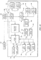
- a diagrammatic representation of the control system of the patient support apparatus 10 is disclosed.
- the lifts 36 and 38 and drives 82, 84, 90, 160, and 162 are controlled by the controller 146 as indicated by the solid arrows.
- the lifts 36 and 38 and drives 82, 84, 90, 160, and 162 include sensor that are used to determine the position of each and provide that information back to the controller 146 as suggested by the dotted lines.
- the drive controller 156 receives inputs from either the caregiver input 260 or the left patient input 138 and right patient input 140. This information is used to control the operation of the left drive motor 142 and right drive motor 144.
- the controller 146 and the motor controller 156 each include a processor and a memory device that stores the instructions that are processed by the processor to effect the control of the various s motors, lifts, and drives. It should be understood that the controller 146 and motor controller 156 may be networked together to share certain data relative to the overall control of the patient support apparatus 10.
- the pendant 250 provides input signals to the controller 146 via the wireless connection as suggested by the dotted lines connecting the two. Similarly, in some embodiments, the pendant 250 receives inductive charging from the power supply 150.
Landscapes
- Health & Medical Sciences (AREA)
- Life Sciences & Earth Sciences (AREA)
- Animal Behavior & Ethology (AREA)
- General Health & Medical Sciences (AREA)
- Public Health (AREA)
- Veterinary Medicine (AREA)
- Nursing (AREA)
- Invalid Beds And Related Equipment (AREA)
- Motorcycle And Bicycle Frame (AREA)
Abstract
Description
- The present disclosure is related to patient support apparatuses that are used for procedures and are operable to transport a patient from one location in a healthcare facility to a second location in the healthcare facility. More specifically, the present application is related to a patient support apparatus that is operable as both a procedural stretcher and a wheelchair.
- In the modern healthcare facility, patients are often kept for extended periods in the emergency unit or an observation ward while test are run and the patient is under observation. Due to cost constraints, patients are not administratively admitted until it is determined that their acuity level qualifies for reimbursement for treatment as an in-patient. As such, the patient may spend an extended period in a space that is not a typical hospital room. From this location, the patient may be transported to other portions of the facility for diagnostic testing.
- In some instances, the patient may be in significant discomfort, lack mobility, or be otherwise incapacitated. As such, there may be a need to move the patient to other areas in the facility without transferring the patient to another patient support apparatus or transport device. In other cases, the patient may be relatively mobile and independent. However, limiting the use of different patient support/transport devices reduces labor in cleaning the equipment between patients. In addition, there may be clinical advantages to the patient using a patient support apparatus as a transport, such as to promote the patient's independence. As such, there is a need for a patient support apparatus that is adaptable to multiple modes of transport to fill the various roles the transport equipment may fulfill in the patient intake process.
- The present disclosure includes one or more of the features recited in the appended claims and/or the following features which, alone or in any combination, may comprise patentable subject matter.
- According to a first aspect of the present disclosure, a patient support apparatus comprise a base having a variable length, a pair of telescopic lifts extending upwardly from the base, an upper frame supported on the telescopic lifts, the upper frame movable between a chair configuration and a bed configuration, and a pair of independent drive wheels positioned on lateral sides of the base. Each of the drive wheels receives an independent input from a user supported on the patient support apparatus and responsive to the independent input to drive each to move and control the direction of movement of the patient support apparatus over a floor supporting the patient support apparatus.
- In some embodiments, the patient support apparatus further comprises a removable barrier assembly coupled to a foot end of the upper frame.
- In some embodiments, the patient support apparatus further comprises a removable barrier assembly coupled to a head end of the upper frame.
- In some embodiments, a removable barrier assembly comprises a fixed panel and a first movable panel pivotably coupled to the fixed panel providing a barrier at an end of the patient support apparatus, the movable panel movable between a barrier position providing a barrier along a portion of a lateral side of the patient support apparatus and an out of the way position.
- In some embodiments, the removable barrier assembly further comprises a second movable panel pivotably coupled to the fixed panel on a side opposite the first movable panel, the second movable panel movable between a barrier positon providing a barrier along a portion of the other lateral side of the patient support apparatus and an out of the way position.
- In some embodiments, the first and second movable panels nest in their respective out of the way positions.
- In some embodiments, a movable panel is pivotable about an axis that is obtuse to the respective barrier surfaces of the end panel and the movable panel.
- In some embodiments, the base comprises at least a first extension that is movable relative to a main portion to extend the length of the base.
- In some embodiments, the first extension is driven by a powered actuator to move the extension relative to the main portion.
- In some embodiments, the base further comprises a second extension that is positioned on a side of the main portion of the base opposite the first extension, the second extension movable relative to the main portion to further extend the length of the base.
- In some embodiments, the actuator is operable to simultaneously move both the first and second extensions to extend or retract the length of the base in unison.
- In some embodiments, the extensions include casters that engage the floor.
- In some embodiments, the casters of each of the extensions and the drive wheels may all engage the floor simultaneously.
- In some embodiments, the base includes a pair of actuators that cooperate to extend and retract the first and second extensions.
- In some embodiments, at least one of the extensions includes a brake operable to lock the casters of the respective extension to prevent the patient support apparatus from moving over the floor.
- In some embodiments, the base includes a foot pedal that is actuable to cause the independent drive wheels to lock or unlock.
- In some embodiments, each drive wheel has a respective user input accessible to a user and associated with the drive wheel, the respective drive wheel responsive to the force applied to the user input associated with the drive wheel.
- In some embodiments, each of the drive wheels is driven by a respective motor.
- In some embodiments, the force applied by a user to a respective user input is multiplied by the motor to provide a drive signal that is larger than the input signal.
- In some embodiments, each time a user actuates a respective user input the user input signal is applied to the respective drive wheel for an equivalent pulse and the drive wheel speed decays to mimic the action of a wheelchair.
- In some embodiments, the user input will receive a signal in either a forward or rear direction and the drive signal of the motor will respond to the direction of the user input to control the speed and direction of the respective drive wheel such that an occupant may use variations in inputs to steer the patient support apparatus.
- According to a second aspect of the present disclosure, a patient support apparatus is movable between a bed configuration and a chair configuration, the patient support apparatus having an upper frame and a lift system for moving the upper frame vertically. The patient support apparatus comprises a base having a main portion supporting the lift system and a pair of extensions that are movable between an extended position when the patient support apparatus is in the bed configuration and a retracted position when the patient support apparatus is in the chair configuration, each of the pair of extensions extending from opposite longitudinal sides of the main portion, the extensions moving in unison to vary the length of the base based on the position of components of the upper frame.
- In some embodiments, the extensions move in proportion to one another.
- In some embodiments, the movement of a first one of the pair of extensions relative to the main portion is transferred directly to the second one of the pair of extensions to cause the extensions to move in proportion to one another.
- In some embodiments, movement of a first one of the pair of extensions is caused by a drive that is interposed between the main portion and the first one of the pair of extensions, the drive extending and retracting to change the position of the extension relative to the main portion.
- In some embodiments, a transmission transfers the movement of the first one of the pair of extensions to the second one of the pair of extensions so that the movement of the drive is transferred through the transmission to the second one of the pair of extensions.
- In some embodiments, the transmission is interposed between the first one and the second one of the pair of extensions.
- In some embodiments, the transmission comprises a drive rack coupled to the first one of the pair of extensions, a follower rack coupled to the second one of the pair of extensions, and wherein a pinion is interposed between the drive rack and the follower rack to transfer motion of the drive rack to the follower rack to thereby move the second one of the pair of extensions in unison with the first one of the pair of extensions.
- In some embodiments, the patient support apparatus further comprises a controller operable to receive position information from drives that control the configuration of the upper frame, and wherein the signals from the position information of the drives that control the configuration of the upper frame are processed by the controller to determine the amount of extension necessary to stabilize the patient support apparatus, the controller causing the pair of extensions to move based on the position information of the drives that control the configuration of the upper frame to stabilize the patient support apparatus.
- In some embodiments, the controller is further operable to cause movement of the extensions to prevent interference with components of the upper frame, the decision to move the extensions being dependent on the position of one or more members of the upper frame.
- In some embodiments, the extensions are fully extended when the patient support apparatus is in the bed configuration and fully retracted when the patient support apparatus is in the chair configuration.
- According to a third aspect of the present disclosure, the patient support apparatus comprises a drive system including at least two inputs accessible by a user when the patient support apparatus is in the chair configuration, the user inputs providing a signal to the drive system to control the speed and direction of the patient support apparatus over a floor supporting the patient support apparatus based on the composite signal of the at least two inputs.
- In some embodiments, the at least two inputs each include a force sensor operable to detect both a direction and magnitude of a force applied to the respective user input.
- In some embodiments, the drive system includes at least two drive wheels, the drive wheels responsive to the resultant input of the at least two user inputs.
- In some embodiments, the two user inputs are operable to cause the patient support apparatus to move forward, make a forward turn, move in reverse, and make a reverse turn.
- In some embodiments, the user inputs are each fixed relative to a respective drive wheel.
- In some embodiments, the user inputs are each movable with a respective drive wheel.
- In some embodiments, the patient support apparatus further comprises a controller which is operable to multiply the user input force to cause the wheels to be driven at a rate that offsets the weight of the patient support apparatus.
- In some embodiments, the drive system includes a separate drive motor operable to drive respective drive wheel in either a forward or reverse direction.
- Additional features, which alone or in combination with any other feature(s), such as those listed above and/or those listed in the claims, can comprise patentable subject matter and will become apparent to those skilled in the art upon consideration of the following detailed description of various embodiments exemplifying the best mode of carrying out the embodiments as presently perceived.
- The detailed description particularly refers to the accompanying figures in which:
-
Fig. 1 is a perspective view of a patient support apparatus according to the present disclosure, the patient support apparatus being shown in a bed configuration with the head end of the being positioned on the left side ofFig. 1 ; -
Fig. 2 is a perspective view of a patient support apparatus similar to the patient support apparatus shown inFig. 1 , the patient support apparatus ofFig. 2 being shown in a chair configuration with the head end being positioned on the left side ofFig. 2 and with a foot end barrier assembly removed; -
Fig. 3 is a perspective view of the patient support apparatus ofFig. 2 in a bed configuration, the foot end barrier assembly present, and a patient supported on a mattress of the patient support apparatus; -
Fig. 4 is a perspective view of the patient support apparatus ofFig. 2 with a patient positioned on the patient support apparatus and with a left head end barrier moved to an out of the way position; -
Fig. 5 is a perspective view of the patient support apparatus ofFig. 4 , from a different perspective than the view ofFig. 4, Fig. 5 showing the back of a head end of an upper frame of the patient support apparatus; -
Fig. 6 is a perspective view of the patient support apparatus ofFig. 4 with the head end barrier in the barrier position; -
Fig. 7 is a perspective view of the patient support apparatus similar toFig. 5 with the head end barrier in the barrier position; -
Fig. 8 is a top perspective view of the patient support apparatus ofFig. 7 ; -
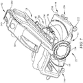
Fig. 9 is a perspective view of the patient support apparatus ofFig. 5 with portions removed to show the frame structure and the componentry of the base including drive motors, the patient support apparatus being viewed from behind the patient's right; -
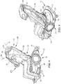
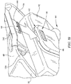
Fig. 10 is a perspective view of a portion of the patient support apparatus ofFig. 2 ; -
Fig. 10 showing the engagement of the head end barrier assembly with a portion of the upper frame of the patient support apparatus; -
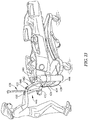
Fig 11 is a perspective view of the patient support apparatus ofFig. 9 with the portions removed, the patient support apparatus being viewed from the patient's left foot; -
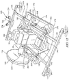
Fig. 12 is a perspective view of the base of the patient support apparatus ofFig. 11 with portions removed, the base of the patient support apparatus ofFig. 12 having a pair of extensions extended to lengthen the base to improve stability for the bed configuration; -
Fig. 13 is an enlarged view of a portion of the base ofFig. 12 ; -
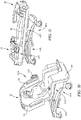
Fig. 14 is another perspective view of the base of the patient support apparatus ofFig. 11 with the portions removed to show additional details relative to the base and the drive system; -
Fig. 15 is a view similar toFig. 12 with the extension's retracted and showing additional details; -
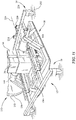
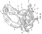
Fig. 16 is a perspective view of the patient support apparatus ofFig. 5 with portions removed to show the frame structure and the componentry of the base including drive motors, the patient support apparatus being viewed from behind the patient's left; -
Fig. 17 is a diagrammatic view of the kinematic structure of the patient support apparatus ofFig. 2 showing the interaction of movable components of the upper frame of the patient support apparatus while the patient support apparatus is in a chair configuration; -
Fig. 18 is a diagrammatic view similar toFig. 17 ,Fig. 18 showing the patient support apparatus in a bed configuration; -
Fig. 19 is a diagrammatic view similar toFig. 18 ,Fig. 19 showing the patient support apparatus in a bed configuration, the bed in a tilt condition; -
Fig. 20 is a perspective view of another embodiment of patient support apparatus according to the present disclosure, the patient support apparatus ofFig. 20 having a different lift system and lacking a drive system present on the embodiments ofFigs. 1-19 , the patient support apparatus ofFig. 20 shown in a chair configuration; -
Fig. 21 is a perspective view of the embodiment of patient support apparatus ofFig. 20 , the patient support apparatus shown in a bed configuration inFig. 21 ; -
Fig. 22 is a perspective view of the patient support apparatus ofFigs. 20-21 with an alternate head end structure that includes an alternate push handle input and accessory support structure; -
Fig. 23 is another view of the embodiment ofFig. 22 ; -
Fig. 24 is illustrates the ability of the push handles of the embodiment ofFigs. 22-23 to be stowed to an out of the way position; and -
Fig. 25 is block diagram of the patient support apparatus ofFigs. 1-19 . - The present disclosure includes a
patient support apparatus 10 that is convertible between a bed configuration shown inFig. 1 and a chair/wheelchair configuration shown inFig. 2 . Thepatient support apparatus 10 includes a base 12 that is expandable so that afirst extension 14 and asecond extension 16 may be extended from acentral portion 18 of the base 12 to improve the stability of thepatient support apparatus 10 in the bed configuration. Theextensions Fig. 2 to provide clearance for afoot section 30 when thepatient support apparatus 10 is moved to the chair configuration. Thecentral portion 18 of thebase 12 supports alift system 20 and adrive system 22, each of which will be discussed in further detail below. Theupper frame 24 of thepatient support apparatus 10 includes ahead section 26, aseat section 28, and thefoot section 30. Thehead section 26 and thefoot section 30 are pivotable relative to theseat section 28, as will be discussed in further below. Thepatient support apparatus 10 also includes a headend barrier assembly 32 and a footend barrier assembly 34. Thebarrier assemblies - Referring to
Fig. 19 , thelift system 20 includes lifts embodied as a telescopichead end column 36 and a telescopicfoot end column 38, each of which is independently extendable so that theupper frame 24 may be tilted about a lateralhorizontal axis 40 as indicated byarrow 42. Thelifts central portion 18 of thebase 12 and pivotably coupled to theupper frame 24 at separate locations so that extension or retraction of either one of thelifts lifts upper frame 24. In use, thelifts upper frame 24. The telescopic column lifts 36 and 38 may be embodied similar to the hi-lo lift units of the CareAssist® ES Medical Surgical bed from Hill-Rom, Inc. of Batesville, Indiana. - When present, the head
end barrier assembly 32 includes ahead end panel 48 that is fixed to thehead section 26. A lefthand head panel 50 is pivotably coupled to thehead end panel 48 and pivotable about anaxis 52 to move between the deployed position shown inFig. 2 and a retracted position shown inFig. 4 . Referring toFig. 2 , a righthand head panel 54 is pivotably coupled to thepanel 48 and pivotable about anaxis 56 to a retracted position similar to the retracted position ofpanel 50 inFig. 4 . Theaxes panels panels panel 50 being positioned outboard of thepanel 54. - Referring to
Fig. 10 , the headend barrier assembly 32 is secured to theupper frame 24 by atab 60 which is received into areceiver 62 formed in ahead end arm 64 of theupper frame 24. Thetab 60 is formed to include achannel 66 which is engaged by a spring-loadedgrip 58 which has a pawl (not shown) that is positioned in thechannel 66 when thetab 60 is positioned in thereceiver 62. The pawl of thegrip 58 prevents the headend barrier assembly 32 from being removed unless ahandle 68 is actuated, which disengages the pawl and allows thetab 60 to be removed from thehead end arm 64 such that the entire headend barrier assembly 32 can be removed from thepatient support apparatus 10. Footend barrier assembly 34 is removably coupled to a foot end arm 70 (seen inFig. 11 ) in a manner similar to the way in which headend barrier assembly 32 is secured to thehead end arm 64. - With further reference to
Fig. 11 , theupper frame 24 includes thehead end arm 64, thefoot end arm 70, athigh portion 72 and aseat portion 74. Theseat portion 74 is pivotably coupled to the telescopichead end column 36 and a telescopicfoot end column 38 and the movement of the telescopichead end column 36 and a telescopicfoot end column 38 control the overall tilt of thehead end arm 64, thefoot end arm 70, thethigh portion 72 and theseat portion 74. Thethigh portion 72 is pivotably coupled to theseat portion 74 and may be pivoted about anaxis 80 to adjust the attitude of thethigh portion 72 relative to theseat portion 74 by adrive 82, shown kinematically inFigs. 17-19 . - The
head end arm 64 is also pivotably about anaxis 86 and adjustable relative to theseat portion 74 as shown inFig. 17 with adrive 84. Thefoot end arm 70 is pivotably coupled to thethigh portion 72 and pivotable about anaxis 88 under the power of adrive 90. Using thedrives upper frame 24 elements headend arm 64,foot end arm 70,thigh portion 72 andseat portion 74 may be adjusted between the chair configuration ofFig. 2 and the bed configuration shown inFig. 1 . - Referring again to
Fig. 11 , each of thehead end arm 64, thefoot end arm 70, thethigh portion 72 and theseat portion 74 have a width that is narrower than the width of amattress 92 supported on theupper frame 24. The narrow width of thehead end arm 64, thefoot end arm 70, thethigh portion 72 and theseat portion 74 reduces the weight of the respective elements and improves the clearance under themattress 92. Thefoot end arm 70 includes a pair oflateral beams main portion 98 to underlie themattress 92. Themattress 92 is secured to thebeams mattress 92 to be removably secured to thebeams main portion 98 so that themattress 92 may be fixed to theupper frame 24, while still being easily removed. In one embodiment, themattress 92 includes substrates (not shown) that provide some mechanical support where there is no underlying portion of theupper frame 24 and are secured to the components of theupper frame 24 by straps that include hook and loop fasteners. - Similarly to the
foot end arm 70, thethigh portion 72 includes amain portion 102 and a pair ofbeams main portion 102. Theseat portion 74 also includes amain portion 108 and a pair of laterally extendingbeams head end arm 64 includes amain portion 114, ahead support 116 that is coupled to themain portion 114 with thehead support 116 positioned at an angle relative to themain portion 114 to deflect thehead end 120 of themattress 92 to provide support for a patient's head, regardless of the position of thehead end arm 64. In some embodiments, thehead support 116 is adjustable relative to themain portion 114 about an axis to change the angle between the two so that the elevation of the patient's head may be adjusted. Thehead end arm 64 also includes twobeams main portion 114 to the patient's right side and twobeams main portion 114. Thebeams mattress 92 to be secured to thehead end arm 64 while providing reduced weight and clearance under themattress 92. - Referring now to
Fig. 9 , thedrive system 22 of thepatient support apparatus 10 will be explained in further detail. Thedrive system 22 includes aleft drive unit 130 and aright drive unit 132. Eachdrive unit respective drive wheel respective user input user inputs patient support apparatus 10 when thepatient support apparatus 10 is in the chair configuration. Theuser inputs patient support apparatus 10 over the floor, similar to the functionality of a wheelchair. In some embodiments, thedrive system 22 relies entirely upon the force applied by a user to theuser inputs drive wheels patient support apparatus 10. - Referring to
Figs. 9 and14 , thedrive system 22 includes respectiveleft drive motor 142 andright drive motor 144 which react to theuser inputs respective drive motors drive wheels drive motors user inputs user inputs patient support apparatus 10 that exceeds the weight of a typical wheelchair, overcoming the difficulties of having a stretcher/bed act as a wheelchair, while still allowing a user to control the motion of thepatient support apparatus 10 as a typical wheelchair. - Referring to
Fig. 19 , thedrive system 22 is controlled by adrive controller 156 which processes theuser inputs motors motors drive controller 156, all receive power from abattery module 148. Thebattery module 148 is charged by apower supply 150, which is plugged intomains power 454 by acord 444 when thepatient support apparatus 10 is positioned in fixed location. When thepatient support apparatus 10 is going to be moved, thecord 444 is disconnected from themains power 454 and thepatient support apparatus 10 is operated by thebattery module 148. When thecord 444 is connected tomains power 454, themotors drives mains power 454. When the cord is disconnected, thebattery module 148 is used to power themotors patient support apparatus 10. - Referring now to
Figs. 12-14 , the operation of theextendable base 12 includes the coordinated extension of theextensions main portion 18 of thebase 12. The movement of theextensions drives drives frame 164 of thebase 12. The opposite ends of thedrives respective beams extension 14. Thebeams respective yokes beams beams frame 164 so that the movement of thebeams frame 164. - The
beams respective yokes 176 and 178 which are supported from amember 180 of theframe 164. Theyokes 172 and 176 cooperate to guide the movement of thebeam 166 relative to frame 164, while theyokes beam 168 relative to frame 164. Thus, as thedrives extension 14 is extended relative tomain portion 18 of thebase 12 and as thedrives extension 14 is retracted relative to themain portion 18. - Movement of the
beams drives beams extension 16 through a pair oftransmissions beam 180 is supported on the cross-bar 170 by a yoke 188 and on amember 190 offrame 164 by ayoke 192. Similarly, thebeam 182 is supported on the cross-bar 170 by ayoke 194 and themember 190 by ayoke 196. Thus, the movement of thebeams respective yokes extension 16 relative to theframe 164 andmain portion 18 of thebase 12. Thetransmissions extension 16 to be coordinated with and proportional to the movement of theextension 14. Each transmission comprises adrive rack 200, afollower rack 202, and apinion 204. Thedrive rack 200 of eachtransmission beams extension 14. Thefollower rack 202 of eachtransmission beams extension 16. Thepinion 204 of eachtransmission respective drive rack 200 andfollower rack 202 and supported by the cross-bar 170. Thepinion 204 is rotatable relative to the cross-bar 170 so that as thedrive rack 200 is moved, teeth 210 of thedrive rack 200 engages teeth 212 of thepinion 204 to cause thepinion 204 to rotate. The teeth 212 of thepinion 204 engage teeth 214 of thefollower rack 202 such that the motion of thedrive rack 200 is transferred through thepinion 204 to thefollower rack 202, causing movement of thebeams - In use, the
drives Fig. 9 ) which also controls thedrives lifts base 12 is controlled by the position of theextensions upper frame 24 of thepatient support apparatus 10. In use, theextensions patient support apparatus 10 due to a cantilevered load being positioned to far from the center-of-gravity of thepatient support apparatus 10. As thehead section 26 andfoot section 30 of thepatient support apparatus 10 are moved to the chair configuration, the potential for a tipping issue to arise is reduced. As such, theextensions head section 26 andfoot section 30. Thecontroller 146 receives inputs to control the position of thehead section 26 andfoot section 30 and processes the positions of those components to move theextensions extensions controller 146, which, in turn, controls the operation of thedrives drives lifts controller 146 is able to discern the position of all of the components of thepatient support apparatus 10 at any time and control theextensions patient support apparatus 10 and to provide clearance for other components as necessary. - In some embodiments, the
patient support apparatus 10 also includes an input pedal 220 (seen inFig. 12 , for example) that is actuable by a user to choose a mobility mode of thepatient support apparatus 10. When present, thepedal 220 is supported on a cross-bar 222 of theextension 14 and is movable to three positions which correspond to three modes: neutral, as shown inFig. 12 ; brake, which is achieved when a user steps on apad 224 to cause thepedal 220 to rotate about itsaxis 226 to position pad 224 lower than apad 228, and steer, which is achieved when user steps on thepad 228 and causes thepedal 220 to move to the pad 228 a to a position that is lower than thepad 224. In the brake mode, thepedal 220 actuates a mechanical braking system to lock twocasters extension 14 to prevent them from rotating about a horizontal axis and swiveling about a vertical axis, as is known in the art. In the brake mode, a signal is sent to thedrive controller 156 to cause thedrive wheels patient support apparatus 10 from movement relative to the floor. In the neutral position, thecasters drive wheels patient support apparatus 10 to be moved in a free wheel mode over the floor. In the steer mode, thecasters drive wheels drive controller 156 and driven by themotors patient support apparatus 10 includes a sensor assembly (not shown) which is operable to detect the position of thepedal 220 and provide that information to thedrive controller 156. However, in some embodiments, the mechanical structure that changes the mode of thecasters casters casters patient support apparatus 10 relative to the floor is effected by thedrive wheels - In one embodiment, the
user inputs drive wheels drive wheels user inputs drive controller 156 responds to those inputs to mimic the operation of a wheelchair. In another embodiment, theuser inputs drive wheels user inputs respective drive wheel respective drive wheel - In addition to the
user inputs drive wheels patient support apparatus 10 also includes a caregiverresponsive input 260 positioned in thehead support 116. Thecaregiver input 260 is embodied as a strain gauge that is responsive to pressure applied to thehead end panel 48 at either anupper grip 240 orlower grip 242 shown in the embodiment ofFig. 9 . Pressure on either of thegrips strain gauge 260 and is translated to a drive signal by thedrive controller 156. Thestrain gauge 260 is configured to measure torque applied to thegrips drive wheels patient support apparatus 10 from the input by the caregiver on thegrip grips patient support apparatus 10 is being used to transport the patient in a bed configuration, or when a caregiver has control over thepatient support apparatus 10. Thestrain gauge 260 signal is provided by the caregiver applying pressure to thegrip 240 orgrip 242 overrides any input applied to theuser inputs patient support apparatus 10. - As suggested in
Fig. 8 , a user may apply force in either a forward or rearward direction on the left side of thepatient support apparatus 10 as indicated byarrow 262. Similarly, the user may apply force in the forward or rearward direction on the left side of thepatient support apparatus 10 as indicated byarrow 264. The various resulting motions of thepatient support apparatus 10 are suggested by thearrows patient support apparatus 10 may make a reverse turn as suggested byarrow 266, a forward turn as suggest byarrow 268, or may move forward as indicated byarrow 270 or in reverse as indicated byarrow 272. - In some embodiments, the
patient support apparatus 10 further includes awireless pendant 250 which has user inputs typical of apatient support apparatus 10 that allows a user to provide inputs to thecontroller 146 wirelessly. As shown diagrammatically inFig. 25 , in the illustrative embodiment, thependant 250 communicates to thecontroller 146 using Bluetooth® based protocol, but other wireless protocols may be employed as well. In still other embodiments, thependant 250 may be connected to thecontroller 146 by a wired connection. Thependant 250 may be inductively charged when it is mounted to another component of thepatient support apparatus 10. Thependant 250 includes a touchscreen graphical user interface (GUI) and any functions that are limited to an authorized caregiver are not displayed on the GUI until an authorized user is detected to be in the vicinity of the GUI by a locating and tracking system or by a wireless RFID signal from a caregiver identification tag or system. Thependant 250 is paired with a particularpatient support apparatus 10 and if thependant 250 is taken out of range of thepatient support apparatus 10, the GUI will provide a message to return the pendant to the appropriatepatient support apparatus 10. - Another embodiment of a
patient support apparatus 410 is shown inFigs. 20-21 has anupper frame 412 that functions similarly to theupper frame 24 discussed above. Thepatient support apparatus 410 utilizes a base 414 that does not have any extensions or any ability to extend and retract. Thepatient support apparatus 410 also utilizes acantilevered lift system 416 that is similar to the lift system of the Century CC® bed previously available from Hill-Rom Services, Inc. of Batesville, Indiana. Thepatient support apparatus 410 utilizes a typical brake-steer system, such as that available in the CareAssist® ES bed discussed above. - Referring to
Fig. 22 , an embodiment ofpatient support apparatus 420 is similar to thepatient support apparatus 410, but includes ahead end structure 422 that provides support for accessories as well as a stowable push handle assembly 424. Thestructure 422 includes twoposts base 414 of thepatient support apparatus 420. Theposts respective arms posts arms oxygen tank holder 436 with thearm 432 formed to include areceiver 430 for receiving anIV pole 438. Thearm 434 supports areceiver 440 for securing aplug 442 of apower cord 444. A set of respective push handles 446 and 448 are supported from thearms patient support apparatus 420 over a floor. The push handles 446 and 448 are adjustable relative to thearms grips arms arms arms grips - Referring now to
Fig. 25 , a diagrammatic representation of the control system of thepatient support apparatus 10 is disclosed. Thelifts controller 146 as indicated by the solid arrows. Thelifts controller 146 as suggested by the dotted lines. Thedrive controller 156 receives inputs from either thecaregiver input 260 or the leftpatient input 138 and rightpatient input 140. This information is used to control the operation of theleft drive motor 142 andright drive motor 144. Thecontroller 146 and themotor controller 156 each include a processor and a memory device that stores the instructions that are processed by the processor to effect the control of the various s motors, lifts, and drives. It should be understood that thecontroller 146 andmotor controller 156 may be networked together to share certain data relative to the overall control of thepatient support apparatus 10. Thependant 250 provides input signals to thecontroller 146 via the wireless connection as suggested by the dotted lines connecting the two. Similarly, in some embodiments, thependant 250 receives inductive charging from thepower supply 150. - Although this disclosure refers to specific embodiments, it will be understood by those skilled in the art that various changes in form and detail may be made without departing from the subject matter set forth in the accompanying claims.
- Further aspects of the invention are set out in the following list of clauses, and dependent clauses:
- Clause 1. A patient support apparatus comprising:
- a base having a variable length;
- a pair of telescopic lifts extending upwardly from the base;
- an upper frame supported on the telescopic lifts, the upper frame movable between a chair configuration and a bed configuration; and
- a pair of independent drive wheels positioned on lateral sides of the base, each of the drive wheels receiving an independent input from a user supported on the patient support apparatus and responsive to the independent input to drive each to move and control the direction of movement of the patient support apparatus over a floor supporting the patient support apparatus.
- Clause 2. The patient support apparatus of clause 1, further comprising a removable barrier assembly coupled to a foot end of the upper frame.
- Clause 3. The patient support apparatus of clause 2, wherein the removable barrier assembly comprises a fixed panel and a first movable panel pivotably coupled to the fixed panel, the movable panel movable between a barrier position and an out of the way position.
- Clause 4. The patient support apparatus of clause 3, wherein the removable barrier assembly further comprises a second movable panel pivotably coupled to the fixed panel on a side opposite the first movable panel, the second movable panel movable between a barrier positon and an out of the way position.
- Clause 5. The patient support apparatus of clause 4, wherein the first and second movable panels nest in their respective out of the way positions.
- Clause 6. The patient support apparatus of clause 3, 4 or 5, wherein a movable panel is pivotable about an axis that is obtuse to the respective barrier surfaces of the end panel and the movable panel.
- Clause 7. The patient support apparatus of any preceding clause, wherein the base comprises at least a first extension that is movable relative to a main portion to extend the length of the base.
- Clause 8. The patient support apparatus of clause 7, wherein the first extension is driven by a powered actuator to move the extension relative to the main portion.
- Clause 9. The patient support apparatus of clause 7 or 8, wherein the base further comprises a second extension that is positioned on a side of the main portion of the base opposite the first extension, the second extension movable relative to the main portion to further extend the length of the base.
-
Clause 10. The patient support apparatus of clause 9, wherein the actuator is operable to simultaneously move both the first and second extensions to extend or retract the length of the base in unison. - Clause 11. The patient support apparatus of
clause 9 or 10, wherein the extensions include casters that engage the floor. -
Clause 12. The patient support apparatus of clause 11, wherein the casters of each of the extensions and the drive wheels all engage the floor simultaneously. - Clause 13. The patient support apparatus of any of clauses 9 to 12, wherein the base includes a pair of actuators that cooperate to extend and retract the first and second extensions.
-
Clause 14. The patient support apparatus of clause 13, wherein the extensions include casters that engage the floor and at least one of the extensions includes a brake operable to lock the casters of the respective extension to prevent the patient support apparatus from moving over the floor. - Clause 15. The patient support apparatus of any of the preceding clauses, wherein the base includes a foot pedal that is actuable to cause the independent drive wheels to lock or unlock.
-
Clause 16. The patient support apparatus of any of the preceding clauses, wherein each drive wheel has a respective user input accessible to a user and associated with the drive wheel, the respective drive wheel responsive to the force applied to the user input associated with the drive wheel. - Clause 17. The patient support apparatus of
clause 16, wherein each of the drive wheels is driven by a respective motor. -
Clause 18. The patient support apparatus of clause 17, wherein the force applied by a user to a respective user input is multiplied by the motor to provide a drive signal that is larger than the input signal. - Clause 19. The patient support apparatus of
clause 18, where each time a user actuates a respective user input the user input signal is applied to the respective drive wheel for an equivalent pulse and the drive wheel speed decays to mimic the action of a wheelchair. -
Clause 20. The patient support apparatus ofclause 18 or 19, wherein the user input will receive a signal in either a forward or rear direction and the drive signal of the motor will respond to the direction of the user input to control the speed and direction of the respective drive wheel such that an occupant may use variations in inputs to steer the patient support apparatus. - Clause 21. A patient support apparatus movable between a bed configuration and a chair configuration, the patient support apparatus having an upper frame and a lift system for moving the upper frame vertically, the patient support apparatus comprising:
a base having a main portion supporting the lift system and a pair of extensions that are movable between an extended position when the patient support apparatus is in the bed configuration and a retracted position when the patient support apparatus is in the chair configuration, each of the pair of extensions extending from opposite longitudinal sides of the main portion, the extensions moving in unison to vary the length of the base based on the position of components of the upper frame. -
Clause 22. The patient support apparatus of clause 21, wherein the extensions move in proportion to one another. - Clause 23. The patient support apparatus of
clause 22, wherein the movement of a first one of the pair of extensions relative to the main portion is transferred directly to the second one of the pair of extensions to cause the extensions to move in proportion to one another. -
Clause 24. The patient support apparatus ofclause 21, 22 or 23, wherein movement of a first one of the pair of extensions is caused by a drive that is interposed between the main portion and the first one of the pair of extensions, the drive extending and retracting to change the position of the extension relative to the main portion. - Clause 25. The patient support apparatus of
clause 24, wherein a transmission transfers the movement of the first one of the pair of extensions to the second one of the pair of extensions so that the movement of the drive is transferred through the transmission to the second one of the pair of extensions. -
Clause 26. The patient support apparatus of clause 25, wherein the transmission is interposed between the first one and the second one of the pair of extensions. - Clause 27. The patient support apparatus of
clause 25 or 26, wherein the transmission comprises a drive rack coupled to the first one of the pair of extensions, a follower rack coupled to the second one of the pair of extensions, and wherein a pinion is interposed between the drive rack and the follower rack to transfer motion of the drive rack to the follower rack to thereby move the second one of the pair of extensions in unison with the first one of the pair of extensions. -
Clause 28. The patient support apparatus of any ofclauses 24 to 27, wherein the patient support apparatus further comprises a controller operable to receive position information from drives that control the configuration of the upper frame, and wherein the signals from the position information of the drives that control the configuration of the upper frame are processed by the controller to determine the amount of extension necessary to stabilize the patient support apparatus, the controller causing the pair of extensions to move based on the position information of the drives that control the configuration of the upper frame to stabilize the patient support apparatus. - Clause 29. The patient support apparatus of
clause 28, wherein the controller is further operable to cause movement of the extensions to prevent interference with components of the upper frame, the decision to move the extensions being dependent on the position of one or more members of the upper frame. -
Clause 30. The patient support apparatus of any of clauses 21 to 29, wherein the extensions are fully extended when the patient support apparatus is in the bed configuration and fully retracted when the patient support apparatus is in the chair configuration. - Clause 31. A patient support apparatus movable between a bed configuration and a chair configuration, the patient support apparatus having an upper frame and a lift system for moving the upper frame vertically, the patient support apparatus comprising
a drive system including at least two inputs accessible by a user when the patient support apparatus is in the chair configuration, the user inputs providing a signal to the drive system to control the speed and direction of the patient support apparatus over a floor supporting the patient support apparatus based on the composite signal of the at least two inputs. -
Clause 32. The patient support apparatus of clause 31, wherein the at least two inputs each include a force sensor operable to detect both a direction and magnitude of a force applied to the respective user input. - Clause 33. The patient support apparatus of
clause 31 or 32, wherein the drive system includes at least two drive wheels, the drive wheels responsive to the resultant input of the at least two user inputs. -
Clause 34. The patient support apparatus of clause 33, wherein the two user inputs are operable to cause the patient support apparatus to move forward, make a forward turn, move in reverse, and make a reverse turn. - Clause 35. The patient support apparatus of
clause 33 or 34, wherein the user inputs are each movable with a respective drive wheel. -
Clause 36. The patient support apparatus ofclause 33, 34 or 35, wherein the patient support apparatus further comprises a controller which is operable to multiply the user input force to cause the wheels to be driven at a rate that offsets the weight of the patient support apparatus. - Clause 37. The patient support apparatus of any of clauses 33 to 36, wherein the drive system includes a separate drive motor operable to drive each respective drive wheel in either a forward or reverse direction.
-
Clause 38. The patient support apparatus ofclause 33 or 34, wherein the user inputs are each fixed relative to a respective drive wheel. - Clause 39. The patient support apparatus of
clause 38, wherein the patient support apparatus further comprises a controller which is operable to multiply the user input force to cause the wheels to be driven at a rate that offsets the weight of the patient support apparatus. -
Clause 40. The patient support apparatus of clause 39, wherein the drive system includes a separate drive motor operable to drive each respective drive wheel in either a forward or reverse direction.
Claims (15)
- A patient support apparatus comprising
a base having a variable length;
a pair of telescopic lifts extending upwardly from the base;
an upper frame supported on the telescopic lifts, the upper frame movable between a chair configuration and a bed configuration; and
a pair of independent drive wheels positioned on lateral sides of the base, each of the drive wheels receiving an independent input from a user supported on the patient support apparatus and responsive to the independent input to drive each to move and control the direction of movement of the patient support apparatus over a floor supporting the patient support apparatus. - The patient support apparatus of claim 1, further comprising a removable barrier assembly coupled to a foot end of the upper frame.
- The patient support apparatus of claim 2, wherein the removable barrier assembly comprises a fixed panel and a first movable panel pivotably coupled to the fixed panel, the movable panel movable between a barrier position and an out of the way position.
- The patient support apparatus of claim 3, wherein the removable barrier assembly further comprises a second movable panel pivotably coupled to the fixed panel on a side opposite the first movable panel, the second movable panel movable between a barrier positon and an out of the way position.
- The patient support apparatus of claim 4, wherein the first and second movable panels nest in their respective out of the way positions.
- The patient support apparatus of claim 3, 4 or 5, wherein a movable panel is pivotable about an axis that is obtuse to the respective barrier surfaces of the end panel and the movable panel.
- The patient support apparatus of any preceding claim, wherein the base comprises at least a first extension that is movable relative to a main portion to extend the length of the base.
- The patient support apparatus of claim 7, wherein the first extension is driven by a powered actuator to move the extension relative to the main portion.
- The patient support apparatus according to claim 7 or 8, wherein the base further comprises a second extension that is positioned on a side of the main portion of the base opposite the first extension, the second extension movable relative to the main portion to further extend the length of the base.
- The patient support apparatus of claim 8 or 9, wherein the actuator is operable to simultaneously move both the first and second extensions to extend or retract the length of the base in unison, and/or wherein the base includes a pair of actuators that cooperate to extend and retract the first and second extensions.
- The patient support apparatus of claim 10, wherein the extensions include casters that engage the floor, and optionally wherein the casters of each of the extensions and the drive wheels all engage the floor simultaneously, and/or wherein at least one of the extensions includes a brake operable to lock the casters of the respective extension to prevent the patient support apparatus from moving over the floor.
- The patient support apparatus of any of the preceding claims, wherein the base includes a foot pedal that is actuable to cause the independent drive wheels to lock or unlock, and/or wherein each drive wheel has a respective user input accessible to a user and associated with the drive wheel, the respective drive wheel responsive to the force applied to the user input associated with the drive wheel.
- The patient support apparatus of claim 12, wherein each of the drive wheels is driven by a respective motor.
- The patient support apparatus of claim 13, wherein the force applied by a user to a respective user input is multiplied by the motor to provide a drive signal that is larger than the input signal.
- The patient support apparatus of claim 14, where each time a user actuates a respective user input the user input signal is applied to the respective drive wheel for an equivalent pulse and the drive wheel speed decays to mimic the action of a wheelchair, and/or wherein the user input will receive a signal in either a forward or rear direction and the drive signal of the motor will respond to the direction of the user input to control the speed and direction of the respective drive wheel such that an occupant may use variations in inputs to steer the patient support apparatus.
Applications Claiming Priority (1)
| Application Number | Priority Date | Filing Date | Title |
|---|---|---|---|
| US201862674369P | 2018-05-21 | 2018-05-21 |
Publications (3)
| Publication Number | Publication Date |
|---|---|
| EP3572057A2 true EP3572057A2 (en) | 2019-11-27 |
| EP3572057A3 EP3572057A3 (en) | 2020-03-18 |
| EP3572057B1 EP3572057B1 (en) | 2025-02-26 |
Family
ID=66625785
Family Applications (1)
| Application Number | Title | Priority Date | Filing Date |
|---|---|---|---|
| EP19175486.0A Active EP3572057B1 (en) | 2018-05-21 | 2019-05-20 | Patient support apparatus adaptable to multiple modes of transport |
Country Status (2)
| Country | Link |
|---|---|
| US (3) | US11628102B2 (en) |
| EP (1) | EP3572057B1 (en) |
Cited By (1)
| Publication number | Priority date | Publication date | Assignee | Title |
|---|---|---|---|---|
| WO2021185613A1 (en) * | 2020-03-19 | 2021-09-23 | IFP Energies Nouvelles | Removable electric propulsion system for a rolling object comprising a foldable seating device |
Families Citing this family (6)
| Publication number | Priority date | Publication date | Assignee | Title |
|---|---|---|---|---|
| US10744048B2 (en) * | 2018-04-09 | 2020-08-18 | Toyota Motor North America, Inc. | Wheelchair apparatuses including usage features |
| US11628102B2 (en) | 2018-05-21 | 2023-04-18 | Hill-Rom Services, Inc. | Patient support apparatus adaptable to multiple modes of transport |
| KR102927930B1 (en) * | 2019-11-18 | 2026-02-19 | 엘지전자 주식회사 | Robot |
| CN111110472B (en) * | 2019-12-30 | 2021-03-12 | 吉林大学 | Integrated nursing bed chair |
| EP4415672A4 (en) * | 2021-10-13 | 2025-10-08 | Stryker Corp | LOAD CELL ARRANGEMENT FOR A PATIENT RECLINING DEVICE |
| US11890244B2 (en) * | 2022-03-18 | 2024-02-06 | Chung-Hsiu Su | Wheeled nursing and medical device |
Family Cites Families (79)
| Publication number | Priority date | Publication date | Assignee | Title |
|---|---|---|---|---|
| US3380546A (en) * | 1966-02-14 | 1968-04-30 | Rodney R. Rabjohn | Traction drive for small vehicles |
| US3544127A (en) * | 1967-11-06 | 1970-12-01 | Peter V Dobson | Trucks |
| US3848883A (en) * | 1973-08-08 | 1974-11-19 | S Breacain | Wheelchair anti-tip apparatus |
| NO143484C (en) * | 1977-03-14 | 1981-02-25 | Sentralinstituttet For Ind For | STEERABLE, ENGINE WHEELS. |
| US4422515A (en) * | 1981-07-29 | 1983-12-27 | The United States of America as represented by the Admin. of Veterans Affairs | Motorized wheel chair |
| US4613151A (en) | 1984-02-16 | 1986-09-23 | Kielczewski William J | High/low extension-lift power wheelchair |
| RU2128479C1 (en) * | 1988-03-23 | 1999-04-10 | Хилл-Ром, Инк. | Patient supporting device (variants) and method of supporting the man's body on mattress |
| ES2069101T3 (en) | 1989-06-30 | 1995-05-01 | Klaus M Moses | DEVICE TO APPLY INFORMATION ON AN OPTICAL REGISTRY SUPPORT. |
| SE9000037D0 (en) | 1990-01-05 | 1990-01-05 | Sinpro Ab | DEVICE LIFTING AND TRANSPORTING OBJECTS |
| US5083625A (en) * | 1990-07-02 | 1992-01-28 | Bleicher Joel N | Powdered maneuverable hospital cart |
| US5366036A (en) * | 1993-01-21 | 1994-11-22 | Perry Dale E | Power stand-up and reclining wheelchair |
| US6212714B1 (en) * | 1995-01-03 | 2001-04-10 | Hill-Rom, Inc. | Hospital bed and mattress having a retracting foot section |
| US7017208B2 (en) * | 1995-08-04 | 2006-03-28 | Hill-Rom Services, Inc. | Hospital bed |
| US5682631A (en) * | 1995-08-04 | 1997-11-04 | Hill-Rom, Inc. | Bed having a reduced-shear pivot and step deck combination |
| CA2224388C (en) | 1996-04-12 | 2002-01-08 | Nippon Clean Engine Research Institute Co., Ltd. | Method of moving human body lying on his side |
| US5806111A (en) * | 1996-04-12 | 1998-09-15 | Hill-Rom, Inc. | Stretcher controls |
| US7010369B2 (en) * | 1997-11-07 | 2006-03-07 | Hill-Rom Services, Inc. | Medical equipment controller |
| US6739006B2 (en) * | 1997-11-07 | 2004-05-25 | Hill-Rom Services, Inc. | Head section support for a surgical table apparatus |
| US6073289A (en) * | 1997-12-18 | 2000-06-13 | Hill-Rom, Inc. | Air fluidized bed |
| US6282738B1 (en) | 1998-08-07 | 2001-09-04 | Hill-Rom, Inc. | Ob/Gyn stretcher |
| US7834768B2 (en) * | 1999-03-05 | 2010-11-16 | Hill-Rom Services, Inc. | Obstruction detection apparatus for a bed |
| US6321878B1 (en) * | 1999-03-05 | 2001-11-27 | Hill-Rom Services, Inc. | Caster and braking system |
| US6398409B1 (en) * | 1999-03-16 | 2002-06-04 | Hill-Rom Services, Inc. | Patient support with digital X-ray cassette |
| US6427264B1 (en) * | 1999-03-19 | 2002-08-06 | Hill-Rom Services, Inc. | Gap filler for bed |
| US6330926B1 (en) * | 1999-09-15 | 2001-12-18 | Hill-Rom Services, Inc. | Stretcher having a motorized wheel |
| US6154690A (en) * | 1999-10-08 | 2000-11-28 | Coleman; Raquel | Multi-feature automated wheelchair |
| US6598247B1 (en) * | 1999-10-27 | 2003-07-29 | Hill-Rom Services, Inc. | Stretcher with mechanical power assist |
| AU2744701A (en) * | 1999-12-29 | 2001-07-09 | Hill-Rom Services, Inc. | Hospital bed |
| US6421854B1 (en) * | 2000-02-18 | 2002-07-23 | Hill-Rom Services, Inc. | Imaging stretcher |
| US7014000B2 (en) * | 2000-05-11 | 2006-03-21 | Hill-Rom Services, Inc. | Braking apparatus for a patient support |
| US8306635B2 (en) * | 2001-03-07 | 2012-11-06 | Motion Games, Llc | Motivation and enhancement of physical and mental exercise, rehabilitation, health and social interaction |
| US7090042B2 (en) * | 2001-03-12 | 2006-08-15 | Jervis B. Webb Company | Floating drive for vehicle |
| US20040124017A1 (en) * | 2001-03-30 | 2004-07-01 | Jones David Lane | Apparatus and method for weighing the occupant of a bed |
| US6874800B2 (en) * | 2001-09-05 | 2005-04-05 | Hill-Rom Services, Inc. | Hospital bed wheel linkage apparatus |
| US6865775B2 (en) * | 2001-09-05 | 2005-03-15 | Hill-Rom Services, Inc. | Hospital bed caster apparatus |
| US6752224B2 (en) * | 2002-02-28 | 2004-06-22 | Stryker Corporation | Wheeled carriage having a powered auxiliary wheel, auxiliary wheel overtravel, and an auxiliary wheel drive and control system |
| US7073220B2 (en) * | 2002-09-06 | 2006-07-11 | Hill-Rom Services, Inc. | Bed siderail having a latch |
| US6916056B2 (en) * | 2002-10-18 | 2005-07-12 | Godby Enterprises, Llc | Bariatric gurney and process |
| US7302717B2 (en) * | 2003-01-22 | 2007-12-04 | Hill-Rom Services, Inc. | Side and end brake/steer mechanism for stretchers |
| US6902178B2 (en) * | 2003-04-28 | 2005-06-07 | O-Matic Corp. | Transport chair for a patient |
| EP2174631B1 (en) * | 2003-05-21 | 2013-06-26 | Hill-Rom Services, Inc. | Hospital bed |
| US7690056B2 (en) * | 2004-03-26 | 2010-04-06 | Millennium Medical Products, Inc. | Stretcher supporter for a storable patient lift and transfer device and method for doing the same |
| US7886380B2 (en) * | 2004-07-28 | 2011-02-15 | Hill-Rom Services, Inc. | Hospital bed |
| WO2006023539A2 (en) * | 2004-08-16 | 2006-03-02 | Kramer Kenneth L | Home care equipment system |
| US20070182220A1 (en) | 2005-02-22 | 2007-08-09 | Walkinshaw Nathan R | Folding Chair Cot For Use With Emergency Vehicles |
| US8069513B2 (en) | 2006-01-19 | 2011-12-06 | Hill-Rom Services, Inc. | Patient support apparatus having auto contour |
| US7922183B2 (en) * | 2006-01-19 | 2011-04-12 | Hill-Rom Services, Inc. | Stretcher having hand actuated wheel braking apparatus |
| WO2007092526A2 (en) * | 2006-02-08 | 2007-08-16 | Hill-Rom Services, Inc. | End panel for a patient-support apparatus |
| US7953537B2 (en) * | 2008-02-29 | 2011-05-31 | Hill-Rom Services, Inc. | Algorithm for power drive speed control |
| US8296884B2 (en) * | 2008-03-13 | 2012-10-30 | Hill-Rom Services, Inc. | Siderail gap filler |
| US8176584B2 (en) * | 2008-08-29 | 2012-05-15 | Hill-Rom Services, Inc. | Patient-support apparatus with movable top |
| US8752220B2 (en) * | 2009-07-10 | 2014-06-17 | Hill-Rom Services, Inc. | Systems for patient support, monitoring and treatment |
| US8437876B2 (en) * | 2009-08-07 | 2013-05-07 | Hill-Rom Services, Inc. | Patient health based support apparatus configuration |
| US8757308B2 (en) | 2009-09-10 | 2014-06-24 | Hill-Rom Services Inc. | Powered transport system and control methods |
| US8442738B2 (en) | 2009-10-12 | 2013-05-14 | Stryker Corporation | Speed control for patient handling device |
| US8607378B2 (en) * | 2010-03-09 | 2013-12-17 | Hill-Rom Services, Inc. | Caregiver assist device |
| US8844073B2 (en) * | 2010-06-07 | 2014-09-30 | Hill-Rom Services, Inc. | Apparatus for supporting and monitoring a person |
| US8646131B2 (en) * | 2010-07-30 | 2014-02-11 | Hill-Rom Services, Inc. | Variable height siderail |
| US8713727B2 (en) * | 2010-07-30 | 2014-05-06 | Hill-Rom Services, Inc. | Siderail assembly for patient support apparatus |
| US8973187B2 (en) * | 2010-07-30 | 2015-03-10 | Hill-Rom Services, Inc. | Bed frame assembly with a lift system having a translatable carriage |
| DE202010017965U1 (en) * | 2010-09-22 | 2013-05-02 | Ulrich Alber Gmbh | Auxiliary drive device, wheelchair and device for determining physical performance data of a wheelchair user |
| US8381337B2 (en) * | 2010-10-29 | 2013-02-26 | Hill-Rom Services, Inc. | Egress assist footboard |
| US8353071B2 (en) * | 2010-12-01 | 2013-01-15 | Hill-Rom Services, Inc. | Removable integrated board and partial foot section |
| US8341779B2 (en) * | 2010-12-06 | 2013-01-01 | Hill-Rom Services, Inc. | Retractable foot caster supports |
| US8266742B2 (en) * | 2010-12-06 | 2012-09-18 | Hill-Rom Services, Inc. | Biometric bed configuration |
| US20120246830A1 (en) * | 2011-03-31 | 2012-10-04 | Hornbach David W | Footboard egress design |
| CN102805691B (en) | 2011-05-30 | 2016-04-13 | 朱盛楠 | A kind of Novel multifunctional medical wheel stretcher |
| US20130061392A1 (en) * | 2011-09-08 | 2013-03-14 | Robert Mark Zerhusen | Combination Perimeter Element and Support Boom |
| US8607388B1 (en) * | 2012-07-10 | 2013-12-17 | Hill-Rom Services, Inc. | Patient-support apparatus having patient entertainment projector |
| US9707143B2 (en) * | 2012-08-11 | 2017-07-18 | Hill-Rom Services, Inc. | Person support apparatus power drive system |
| JP6126479B2 (en) * | 2012-09-14 | 2017-05-10 | ヤマハ発動機株式会社 | Wheelchair wheel, wheelchair |
| US9731784B2 (en) * | 2013-07-04 | 2017-08-15 | Yamaha Hatsudoki Kabushiki Kaisha | Wheelchair electric device, electric wheelchair with wheelchair electric device and drive monitoring method for electric wheelchair |
| AU2014317772B2 (en) * | 2013-09-06 | 2019-04-11 | Stryker Corporation | Patient support usable with bariatric patients |
| CZ305564B6 (en) * | 2013-11-07 | 2015-12-09 | MORAVSKĂť VĂťZKUM, s.r.o. | Robotic mobile modifiable bed |
| EP2883523A1 (en) | 2013-12-10 | 2015-06-17 | Hota Industrial MFG Co., Ltd. | Modular mobile vehicle with an adjustable wheelbase |
| US9132051B2 (en) * | 2014-01-15 | 2015-09-15 | Hill-Rom Services, Inc. | Person support apparatuses with exercise functionalities |
| US10603234B2 (en) | 2016-03-30 | 2020-03-31 | Stryker Corporation | Patient support apparatuses with drive systems |
| US11389348B2 (en) * | 2018-03-29 | 2022-07-19 | Stryker Corporation | Patient transport apparatus having powered drive system utilizing dual mode user input control |
| US11628102B2 (en) | 2018-05-21 | 2023-04-18 | Hill-Rom Services, Inc. | Patient support apparatus adaptable to multiple modes of transport |
-
2019
- 2019-05-16 US US16/413,830 patent/US11628102B2/en active Active
- 2019-05-20 EP EP19175486.0A patent/EP3572057B1/en active Active
-
2023
- 2023-04-06 US US18/296,585 patent/US12336941B2/en active Active
-
2025
- 2025-06-20 US US19/244,137 patent/US20250312210A1/en active Pending
Cited By (3)
| Publication number | Priority date | Publication date | Assignee | Title |
|---|---|---|---|---|
| WO2021185613A1 (en) * | 2020-03-19 | 2021-09-23 | IFP Energies Nouvelles | Removable electric propulsion system for a rolling object comprising a foldable seating device |
| FR3108302A1 (en) * | 2020-03-19 | 2021-09-24 | IFP Energies Nouvelles | Removable electric propulsion system for a rolling object including a foldable seating device |
| JP2023518468A (en) * | 2020-03-19 | 2023-05-01 | イエフペ エネルジ ヌヴェル | Detachable electric propulsion system for vehicles with folding seat arrangements |
Also Published As
| Publication number | Publication date |
|---|---|
| US11628102B2 (en) | 2023-04-18 |
| US20190350780A1 (en) | 2019-11-21 |
| US12336941B2 (en) | 2025-06-24 |
| US20230248593A1 (en) | 2023-08-10 |
| US20250312210A1 (en) | 2025-10-09 |
| EP3572057A3 (en) | 2020-03-18 |
| EP3572057B1 (en) | 2025-02-26 |
Similar Documents
| Publication | Publication Date | Title |
|---|---|---|
| US12336941B2 (en) | Patient support apparatus having detachable barrier assembly | |
| AU2020277119B2 (en) | Reconfigurable transport apparatus | |
| US20220202634A1 (en) | Patient Support Apparatus With Adaptive User Interface | |
| AU2019202383B2 (en) | Methods and systems for automatically articulating cots | |
| US10314754B2 (en) | Patient care and transport assembly | |
| EP1912611B1 (en) | Patient transfer system | |
| US9931259B2 (en) | Drive system for bed | |
| US20170056267A1 (en) | Transport appratus | |
| KR20150038051A (en) | Automated systems for powered cots | |
| US20180271729A1 (en) | Patient bed having translatable siderail for bed exit | |
| WO2011028761A2 (en) | Patient lifting and support device | |
| US10660811B2 (en) | Assistive toileting and weighing device | |
| US20120068838A1 (en) | Bariatric Patient Lift Apparatus | |
| US20150231008A1 (en) | System for propelling hospital bed |
Legal Events
| Date | Code | Title | Description |
|---|---|---|---|
| PUAI | Public reference made under article 153(3) epc to a published international application that has entered the european phase |
Free format text: ORIGINAL CODE: 0009012 |
|
| STAA | Information on the status of an ep patent application or granted ep patent |
Free format text: STATUS: THE APPLICATION HAS BEEN PUBLISHED |
|
| AK | Designated contracting states |
Kind code of ref document: A2 Designated state(s): AL AT BE BG CH CY CZ DE DK EE ES FI FR GB GR HR HU IE IS IT LI LT LU LV MC MK MT NL NO PL PT RO RS SE SI SK SM TR |
|
| AX | Request for extension of the european patent |
Extension state: BA ME |
|
| PUAL | Search report despatched |
Free format text: ORIGINAL CODE: 0009013 |
|
| AK | Designated contracting states |
Kind code of ref document: A3 Designated state(s): AL AT BE BG CH CY CZ DE DK EE ES FI FR GB GR HR HU IE IS IT LI LT LU LV MC MK MT NL NO PL PT RO RS SE SI SK SM TR |
|
| AX | Request for extension of the european patent |
Extension state: BA ME |
|
| RIC1 | Information provided on ipc code assigned before grant |
Ipc: A61G 7/053 20060101ALN20200212BHEP Ipc: A61G 5/04 20130101ALI20200212BHEP Ipc: A61G 5/10 20060101ALI20200212BHEP Ipc: A61G 7/05 20060101ALN20200212BHEP Ipc: A61G 7/015 20060101ALN20200212BHEP Ipc: A61G 7/018 20060101ALN20200212BHEP Ipc: A61G 7/08 20060101ALN20200212BHEP Ipc: A61G 7/005 20060101ALN20200212BHEP Ipc: A61G 5/00 20060101AFI20200212BHEP |
|
| STAA | Information on the status of an ep patent application or granted ep patent |
Free format text: STATUS: REQUEST FOR EXAMINATION WAS MADE |
|
| 17P | Request for examination filed |
Effective date: 20200918 |
|
| RBV | Designated contracting states (corrected) |
Designated state(s): AL AT BE BG CH CY CZ DE DK EE ES FI FR GB GR HR HU IE IS IT LI LT LU LV MC MK MT NL NO PL PT RO RS SE SI SK SM TR |
|
| STAA | Information on the status of an ep patent application or granted ep patent |
Free format text: STATUS: EXAMINATION IS IN PROGRESS |
|
| 17Q | First examination report despatched |
Effective date: 20220930 |
|
| GRAP | Despatch of communication of intention to grant a patent |
Free format text: ORIGINAL CODE: EPIDOSNIGR1 |
|
| STAA | Information on the status of an ep patent application or granted ep patent |
Free format text: STATUS: GRANT OF PATENT IS INTENDED |
|
| RIC1 | Information provided on ipc code assigned before grant |
Ipc: A61G 7/05 20060101ALN20240416BHEP Ipc: A61G 7/08 20060101ALN20240416BHEP Ipc: A61G 7/053 20060101ALN20240416BHEP Ipc: A61G 7/018 20060101ALN20240416BHEP Ipc: A61G 7/015 20060101ALN20240416BHEP Ipc: A61G 7/005 20060101ALN20240416BHEP Ipc: A61G 5/10 20060101ALI20240416BHEP Ipc: A61G 5/04 20130101ALI20240416BHEP Ipc: A61G 5/00 20060101AFI20240416BHEP |
|
| INTG | Intention to grant announced |
Effective date: 20240430 |
|
| GRAJ | Information related to disapproval of communication of intention to grant by the applicant or resumption of examination proceedings by the epo deleted |
Free format text: ORIGINAL CODE: EPIDOSDIGR1 |
|
| STAA | Information on the status of an ep patent application or granted ep patent |
Free format text: STATUS: EXAMINATION IS IN PROGRESS |
|
| GRAP | Despatch of communication of intention to grant a patent |
Free format text: ORIGINAL CODE: EPIDOSNIGR1 |
|
| STAA | Information on the status of an ep patent application or granted ep patent |
Free format text: STATUS: GRANT OF PATENT IS INTENDED |
|
| INTC | Intention to grant announced (deleted) | ||
| RIC1 | Information provided on ipc code assigned before grant |
Ipc: A61G 7/05 20060101ALN20240905BHEP Ipc: A61G 7/08 20060101ALN20240905BHEP Ipc: A61G 7/053 20060101ALN20240905BHEP Ipc: A61G 7/018 20060101ALN20240905BHEP Ipc: A61G 7/015 20060101ALN20240905BHEP Ipc: A61G 7/005 20060101ALN20240905BHEP Ipc: A61G 5/10 20060101ALI20240905BHEP Ipc: A61G 5/04 20130101ALI20240905BHEP Ipc: A61G 5/00 20060101AFI20240905BHEP |
|
| INTG | Intention to grant announced |
Effective date: 20240917 |
|
| GRAS | Grant fee paid |
Free format text: ORIGINAL CODE: EPIDOSNIGR3 |
|
| GRAA | (expected) grant |
Free format text: ORIGINAL CODE: 0009210 |
|
| STAA | Information on the status of an ep patent application or granted ep patent |
Free format text: STATUS: THE PATENT HAS BEEN GRANTED |
|
| AK | Designated contracting states |
Kind code of ref document: B1 Designated state(s): AL AT BE BG CH CY CZ DE DK EE ES FI FR GB GR HR HU IE IS IT LI LT LU LV MC MK MT NL NO PL PT RO RS SE SI SK SM TR |
|
| REG | Reference to a national code |
Ref country code: GB Ref legal event code: FG4D |
|
| REG | Reference to a national code |
Ref country code: CH Ref legal event code: EP |
|
| REG | Reference to a national code |
Ref country code: DE Ref legal event code: R096 Ref document number: 602019066405 Country of ref document: DE |
|
| REG | Reference to a national code |
Ref country code: IE Ref legal event code: FG4D |
|
| REG | Reference to a national code |
Ref country code: NL Ref legal event code: MP Effective date: 20250226 |
|
| PG25 | Lapsed in a contracting state [announced via postgrant information from national office to epo] |
Ref country code: RS Free format text: LAPSE BECAUSE OF FAILURE TO SUBMIT A TRANSLATION OF THE DESCRIPTION OR TO PAY THE FEE WITHIN THE PRESCRIBED TIME-LIMIT Effective date: 20250526 |
|
| PG25 | Lapsed in a contracting state [announced via postgrant information from national office to epo] |
Ref country code: FI Free format text: LAPSE BECAUSE OF FAILURE TO SUBMIT A TRANSLATION OF THE DESCRIPTION OR TO PAY THE FEE WITHIN THE PRESCRIBED TIME-LIMIT Effective date: 20250226 |
|
| PG25 | Lapsed in a contracting state [announced via postgrant information from national office to epo] |
Ref country code: PL Free format text: LAPSE BECAUSE OF FAILURE TO SUBMIT A TRANSLATION OF THE DESCRIPTION OR TO PAY THE FEE WITHIN THE PRESCRIBED TIME-LIMIT Effective date: 20250226 |
|
| PG25 | Lapsed in a contracting state [announced via postgrant information from national office to epo] |
Ref country code: ES Free format text: LAPSE BECAUSE OF FAILURE TO SUBMIT A TRANSLATION OF THE DESCRIPTION OR TO PAY THE FEE WITHIN THE PRESCRIBED TIME-LIMIT Effective date: 20250226 |
|
| REG | Reference to a national code |
Ref country code: LT Ref legal event code: MG9D |
|
| PG25 | Lapsed in a contracting state [announced via postgrant information from national office to epo] |
Ref country code: IS Free format text: LAPSE BECAUSE OF FAILURE TO SUBMIT A TRANSLATION OF THE DESCRIPTION OR TO PAY THE FEE WITHIN THE PRESCRIBED TIME-LIMIT Effective date: 20250626 Ref country code: NO Free format text: LAPSE BECAUSE OF FAILURE TO SUBMIT A TRANSLATION OF THE DESCRIPTION OR TO PAY THE FEE WITHIN THE PRESCRIBED TIME-LIMIT Effective date: 20250526 |
|
| PG25 | Lapsed in a contracting state [announced via postgrant information from national office to epo] |
Ref country code: NL Free format text: LAPSE BECAUSE OF FAILURE TO SUBMIT A TRANSLATION OF THE DESCRIPTION OR TO PAY THE FEE WITHIN THE PRESCRIBED TIME-LIMIT Effective date: 20250226 |
|
| PG25 | Lapsed in a contracting state [announced via postgrant information from national office to epo] |
Ref country code: HR Free format text: LAPSE BECAUSE OF FAILURE TO SUBMIT A TRANSLATION OF THE DESCRIPTION OR TO PAY THE FEE WITHIN THE PRESCRIBED TIME-LIMIT Effective date: 20250226 |
|
| PG25 | Lapsed in a contracting state [announced via postgrant information from national office to epo] |
Ref country code: LV Free format text: LAPSE BECAUSE OF FAILURE TO SUBMIT A TRANSLATION OF THE DESCRIPTION OR TO PAY THE FEE WITHIN THE PRESCRIBED TIME-LIMIT Effective date: 20250226 Ref country code: PT Free format text: LAPSE BECAUSE OF FAILURE TO SUBMIT A TRANSLATION OF THE DESCRIPTION OR TO PAY THE FEE WITHIN THE PRESCRIBED TIME-LIMIT Effective date: 20250626 |
|
| PG25 | Lapsed in a contracting state [announced via postgrant information from national office to epo] |
Ref country code: GR Free format text: LAPSE BECAUSE OF FAILURE TO SUBMIT A TRANSLATION OF THE DESCRIPTION OR TO PAY THE FEE WITHIN THE PRESCRIBED TIME-LIMIT Effective date: 20250527 Ref country code: BG Free format text: LAPSE BECAUSE OF FAILURE TO SUBMIT A TRANSLATION OF THE DESCRIPTION OR TO PAY THE FEE WITHIN THE PRESCRIBED TIME-LIMIT Effective date: 20250226 |
|
| REG | Reference to a national code |
Ref country code: AT Ref legal event code: MK05 Ref document number: 1769945 Country of ref document: AT Kind code of ref document: T Effective date: 20250226 |
|
| PG25 | Lapsed in a contracting state [announced via postgrant information from national office to epo] |
Ref country code: SE Free format text: LAPSE BECAUSE OF FAILURE TO SUBMIT A TRANSLATION OF THE DESCRIPTION OR TO PAY THE FEE WITHIN THE PRESCRIBED TIME-LIMIT Effective date: 20250226 |
|
| PG25 | Lapsed in a contracting state [announced via postgrant information from national office to epo] |
Ref country code: SM Free format text: LAPSE BECAUSE OF FAILURE TO SUBMIT A TRANSLATION OF THE DESCRIPTION OR TO PAY THE FEE WITHIN THE PRESCRIBED TIME-LIMIT Effective date: 20250226 |
|
| PG25 | Lapsed in a contracting state [announced via postgrant information from national office to epo] |
Ref country code: DK Free format text: LAPSE BECAUSE OF FAILURE TO SUBMIT A TRANSLATION OF THE DESCRIPTION OR TO PAY THE FEE WITHIN THE PRESCRIBED TIME-LIMIT Effective date: 20250226 |
|
| PG25 | Lapsed in a contracting state [announced via postgrant information from national office to epo] |
Ref country code: IT Free format text: LAPSE BECAUSE OF FAILURE TO SUBMIT A TRANSLATION OF THE DESCRIPTION OR TO PAY THE FEE WITHIN THE PRESCRIBED TIME-LIMIT Effective date: 20250226 |
|
| PG25 | Lapsed in a contracting state [announced via postgrant information from national office to epo] |
Ref country code: AT Free format text: LAPSE BECAUSE OF FAILURE TO SUBMIT A TRANSLATION OF THE DESCRIPTION OR TO PAY THE FEE WITHIN THE PRESCRIBED TIME-LIMIT Effective date: 20250226 |
|
| PG25 | Lapsed in a contracting state [announced via postgrant information from national office to epo] |
Ref country code: CZ Free format text: LAPSE BECAUSE OF FAILURE TO SUBMIT A TRANSLATION OF THE DESCRIPTION OR TO PAY THE FEE WITHIN THE PRESCRIBED TIME-LIMIT Effective date: 20250226 Ref country code: EE Free format text: LAPSE BECAUSE OF FAILURE TO SUBMIT A TRANSLATION OF THE DESCRIPTION OR TO PAY THE FEE WITHIN THE PRESCRIBED TIME-LIMIT Effective date: 20250226 |
|
| PG25 | Lapsed in a contracting state [announced via postgrant information from national office to epo] |
Ref country code: RO Free format text: LAPSE BECAUSE OF FAILURE TO SUBMIT A TRANSLATION OF THE DESCRIPTION OR TO PAY THE FEE WITHIN THE PRESCRIBED TIME-LIMIT Effective date: 20250226 |
|
| PG25 | Lapsed in a contracting state [announced via postgrant information from national office to epo] |
Ref country code: SK Free format text: LAPSE BECAUSE OF FAILURE TO SUBMIT A TRANSLATION OF THE DESCRIPTION OR TO PAY THE FEE WITHIN THE PRESCRIBED TIME-LIMIT Effective date: 20250226 |
|
| REG | Reference to a national code |
Ref country code: DE Ref legal event code: R097 Ref document number: 602019066405 Country of ref document: DE |
|
| REG | Reference to a national code |
Ref country code: CH Ref legal event code: H13 Free format text: ST27 STATUS EVENT CODE: U-0-0-H10-H13 (AS PROVIDED BY THE NATIONAL OFFICE) Effective date: 20251223 |
|
| PLBE | No opposition filed within time limit |
Free format text: ORIGINAL CODE: 0009261 |
|
| STAA | Information on the status of an ep patent application or granted ep patent |
Free format text: STATUS: NO OPPOSITION FILED WITHIN TIME LIMIT |
|
| PG25 | Lapsed in a contracting state [announced via postgrant information from national office to epo] |
Ref country code: LU Free format text: LAPSE BECAUSE OF NON-PAYMENT OF DUE FEES Effective date: 20250520 |
|
| PG25 | Lapsed in a contracting state [announced via postgrant information from national office to epo] |
Ref country code: CH Free format text: LAPSE BECAUSE OF NON-PAYMENT OF DUE FEES Effective date: 20250531 |
|
| REG | Reference to a national code |
Ref country code: BE Ref legal event code: MM Effective date: 20250531 |
|
| PG25 | Lapsed in a contracting state [announced via postgrant information from national office to epo] |
Ref country code: MC Free format text: LAPSE BECAUSE OF FAILURE TO SUBMIT A TRANSLATION OF THE DESCRIPTION OR TO PAY THE FEE WITHIN THE PRESCRIBED TIME-LIMIT Effective date: 20250226 |
|
| 26N | No opposition filed |
Effective date: 20251127 |
|
| PGFP | Annual fee paid to national office [announced via postgrant information from national office to epo] |
Ref country code: GB Payment date: 20260317 Year of fee payment: 8 |
|
| PG25 | Lapsed in a contracting state [announced via postgrant information from national office to epo] |
Ref country code: IE Free format text: LAPSE BECAUSE OF NON-PAYMENT OF DUE FEES Effective date: 20250520 |
|
| PG25 | Lapsed in a contracting state [announced via postgrant information from national office to epo] |
Ref country code: BE Free format text: LAPSE BECAUSE OF NON-PAYMENT OF DUE FEES Effective date: 20250531 |
|
| PG25 | Lapsed in a contracting state [announced via postgrant information from national office to epo] |
Ref country code: LT Free format text: LAPSE BECAUSE OF FAILURE TO SUBMIT A TRANSLATION OF THE DESCRIPTION OR TO PAY THE FEE WITHIN THE PRESCRIBED TIME-LIMIT Effective date: 20250226 |
|
| PGFP | Annual fee paid to national office [announced via postgrant information from national office to epo] |
Ref country code: DE Payment date: 20260421 Year of fee payment: 8 |
|
| PGFP | Annual fee paid to national office [announced via postgrant information from national office to epo] |
Ref country code: FR Payment date: 20260422 Year of fee payment: 8 |
|
| PG25 | Lapsed in a contracting state [announced via postgrant information from national office to epo] |
Ref country code: CY Free format text: LAPSE BECAUSE OF FAILURE TO SUBMIT A TRANSLATION OF THE DESCRIPTION OR TO PAY THE FEE WITHIN THE PRESCRIBED TIME-LIMIT Effective date: 20250226 |