EP3571983A2 - Catheter with capacitive force sensor - Google Patents
Catheter with capacitive force sensor Download PDFInfo
- Publication number
- EP3571983A2 EP3571983A2 EP19175704.6A EP19175704A EP3571983A2 EP 3571983 A2 EP3571983 A2 EP 3571983A2 EP 19175704 A EP19175704 A EP 19175704A EP 3571983 A2 EP3571983 A2 EP 3571983A2
- Authority
- EP
- European Patent Office
- Prior art keywords
- force sensor
- plate
- catheter
- capacitance
- plates
- Prior art date
- Legal status (The legal status is an assumption and is not a legal conclusion. Google has not performed a legal analysis and makes no representation as to the accuracy of the status listed.)
- Granted
Links
Images






Classifications
-
- A—HUMAN NECESSITIES
- A61—MEDICAL OR VETERINARY SCIENCE; HYGIENE
- A61B—DIAGNOSIS; SURGERY; IDENTIFICATION
- A61B5/00—Measuring for diagnostic purposes; Identification of persons
- A61B5/68—Arrangements of detecting, measuring or recording means, e.g. sensors, in relation to patient
- A61B5/6846—Arrangements of detecting, measuring or recording means, e.g. sensors, in relation to patient specially adapted to be brought in contact with an internal body part, i.e. invasive
- A61B5/6885—Monitoring or controlling sensor contact pressure
-
- A—HUMAN NECESSITIES
- A61—MEDICAL OR VETERINARY SCIENCE; HYGIENE
- A61B—DIAGNOSIS; SURGERY; IDENTIFICATION
- A61B5/00—Measuring for diagnostic purposes; Identification of persons
- A61B5/24—Detecting, measuring or recording bioelectric or biomagnetic signals of the body or parts thereof
- A61B5/25—Bioelectric electrodes therefor
- A61B5/279—Bioelectric electrodes therefor specially adapted for particular uses
- A61B5/28—Bioelectric electrodes therefor specially adapted for particular uses for electrocardiography [ECG]
- A61B5/283—Invasive
- A61B5/287—Holders for multiple electrodes, e.g. electrode catheters for electrophysiological study [EPS]
-
- A—HUMAN NECESSITIES
- A61—MEDICAL OR VETERINARY SCIENCE; HYGIENE
- A61B—DIAGNOSIS; SURGERY; IDENTIFICATION
- A61B18/00—Surgical instruments, devices or methods for transferring non-mechanical forms of energy to or from the body
-
- A—HUMAN NECESSITIES
- A61—MEDICAL OR VETERINARY SCIENCE; HYGIENE
- A61B—DIAGNOSIS; SURGERY; IDENTIFICATION
- A61B18/00—Surgical instruments, devices or methods for transferring non-mechanical forms of energy to or from the body
- A61B18/04—Surgical instruments, devices or methods for transferring non-mechanical forms of energy to or from the body by heating
- A61B18/12—Surgical instruments, devices or methods for transferring non-mechanical forms of energy to or from the body by heating by passing a current through the tissue to be heated, e.g. high-frequency current
-
- A—HUMAN NECESSITIES
- A61—MEDICAL OR VETERINARY SCIENCE; HYGIENE
- A61B—DIAGNOSIS; SURGERY; IDENTIFICATION
- A61B18/00—Surgical instruments, devices or methods for transferring non-mechanical forms of energy to or from the body
- A61B18/04—Surgical instruments, devices or methods for transferring non-mechanical forms of energy to or from the body by heating
- A61B18/12—Surgical instruments, devices or methods for transferring non-mechanical forms of energy to or from the body by heating by passing a current through the tissue to be heated, e.g. high-frequency current
- A61B18/14—Probes or electrodes therefor
-
- A—HUMAN NECESSITIES
- A61—MEDICAL OR VETERINARY SCIENCE; HYGIENE
- A61B—DIAGNOSIS; SURGERY; IDENTIFICATION
- A61B18/00—Surgical instruments, devices or methods for transferring non-mechanical forms of energy to or from the body
- A61B18/04—Surgical instruments, devices or methods for transferring non-mechanical forms of energy to or from the body by heating
- A61B18/12—Surgical instruments, devices or methods for transferring non-mechanical forms of energy to or from the body by heating by passing a current through the tissue to be heated, e.g. high-frequency current
- A61B18/14—Probes or electrodes therefor
- A61B18/1492—Probes or electrodes therefor having a flexible, catheter-like structure, e.g. for heart ablation
-
- A—HUMAN NECESSITIES
- A61—MEDICAL OR VETERINARY SCIENCE; HYGIENE
- A61B—DIAGNOSIS; SURGERY; IDENTIFICATION
- A61B34/00—Computer-aided surgery; Manipulators or robots specially adapted for use in surgery
- A61B34/20—Surgical navigation systems; Devices for tracking or guiding surgical instruments, e.g. for frameless stereotaxis
-
- A—HUMAN NECESSITIES
- A61—MEDICAL OR VETERINARY SCIENCE; HYGIENE
- A61B—DIAGNOSIS; SURGERY; IDENTIFICATION
- A61B5/00—Measuring for diagnostic purposes; Identification of persons
-
- A—HUMAN NECESSITIES
- A61—MEDICAL OR VETERINARY SCIENCE; HYGIENE
- A61B—DIAGNOSIS; SURGERY; IDENTIFICATION
- A61B5/00—Measuring for diagnostic purposes; Identification of persons
- A61B5/68—Arrangements of detecting, measuring or recording means, e.g. sensors, in relation to patient
- A61B5/6846—Arrangements of detecting, measuring or recording means, e.g. sensors, in relation to patient specially adapted to be brought in contact with an internal body part, i.e. invasive
- A61B5/6847—Arrangements of detecting, measuring or recording means, e.g. sensors, in relation to patient specially adapted to be brought in contact with an internal body part, i.e. invasive mounted on an invasive device
- A61B5/6852—Catheters
-
- A—HUMAN NECESSITIES
- A61—MEDICAL OR VETERINARY SCIENCE; HYGIENE
- A61B—DIAGNOSIS; SURGERY; IDENTIFICATION
- A61B5/00—Measuring for diagnostic purposes; Identification of persons
- A61B5/68—Arrangements of detecting, measuring or recording means, e.g. sensors, in relation to patient
- A61B5/6846—Arrangements of detecting, measuring or recording means, e.g. sensors, in relation to patient specially adapted to be brought in contact with an internal body part, i.e. invasive
- A61B5/6847—Arrangements of detecting, measuring or recording means, e.g. sensors, in relation to patient specially adapted to be brought in contact with an internal body part, i.e. invasive mounted on an invasive device
- A61B5/6852—Catheters
- A61B5/6853—Catheters with a balloon
-
- A—HUMAN NECESSITIES
- A61—MEDICAL OR VETERINARY SCIENCE; HYGIENE
- A61B—DIAGNOSIS; SURGERY; IDENTIFICATION
- A61B5/00—Measuring for diagnostic purposes; Identification of persons
- A61B5/68—Arrangements of detecting, measuring or recording means, e.g. sensors, in relation to patient
- A61B5/6846—Arrangements of detecting, measuring or recording means, e.g. sensors, in relation to patient specially adapted to be brought in contact with an internal body part, i.e. invasive
- A61B5/6847—Arrangements of detecting, measuring or recording means, e.g. sensors, in relation to patient specially adapted to be brought in contact with an internal body part, i.e. invasive mounted on an invasive device
- A61B5/6852—Catheters
- A61B5/6857—Catheters with a distal pigtail shape
-
- A—HUMAN NECESSITIES
- A61—MEDICAL OR VETERINARY SCIENCE; HYGIENE
- A61B—DIAGNOSIS; SURGERY; IDENTIFICATION
- A61B90/00—Instruments, implements or accessories specially adapted for surgery or diagnosis and not covered by any of the groups A61B1/00 - A61B50/00, e.g. for luxation treatment or for protecting wound edges
-
- A—HUMAN NECESSITIES
- A61—MEDICAL OR VETERINARY SCIENCE; HYGIENE
- A61B—DIAGNOSIS; SURGERY; IDENTIFICATION
- A61B90/00—Instruments, implements or accessories specially adapted for surgery or diagnosis and not covered by any of the groups A61B1/00 - A61B50/00, e.g. for luxation treatment or for protecting wound edges
- A61B90/06—Measuring instruments not otherwise provided for
-
- A—HUMAN NECESSITIES
- A61—MEDICAL OR VETERINARY SCIENCE; HYGIENE
- A61M—DEVICES FOR INTRODUCING MEDIA INTO, OR ONTO, THE BODY; DEVICES FOR TRANSDUCING BODY MEDIA OR FOR TAKING MEDIA FROM THE BODY; DEVICES FOR PRODUCING OR ENDING SLEEP OR STUPOR
- A61M25/00—Catheters; Hollow probes
- A61M25/10—Balloon catheters
-
- G—PHYSICS
- G01—MEASURING; TESTING
- G01L—MEASURING FORCE, STRESS, TORQUE, WORK, MECHANICAL POWER, MECHANICAL EFFICIENCY, OR FLUID PRESSURE
- G01L1/00—Measuring force or stress, in general
- G01L1/14—Measuring force or stress, in general by measuring variations in capacitance or inductance of electrical elements, e.g. by measuring variations of frequency of electrical oscillators
-
- A—HUMAN NECESSITIES
- A61—MEDICAL OR VETERINARY SCIENCE; HYGIENE
- A61B—DIAGNOSIS; SURGERY; IDENTIFICATION
- A61B17/00—Surgical instruments, devices or methods
- A61B2017/00017—Electrical control of surgical instruments
- A61B2017/00022—Sensing or detecting at the treatment site
- A61B2017/00039—Electric or electromagnetic phenomena other than conductivity, e.g. capacity, inductivity, Hall effect
- A61B2017/00044—Sensing electrocardiography, i.e. ECG
- A61B2017/00048—Spectral analysis
- A61B2017/00053—Mapping
-
- A—HUMAN NECESSITIES
- A61—MEDICAL OR VETERINARY SCIENCE; HYGIENE
- A61B—DIAGNOSIS; SURGERY; IDENTIFICATION
- A61B18/00—Surgical instruments, devices or methods for transferring non-mechanical forms of energy to or from the body
- A61B2018/00005—Cooling or heating of the probe or tissue immediately surrounding the probe
- A61B2018/00011—Cooling or heating of the probe or tissue immediately surrounding the probe with fluids
- A61B2018/00029—Cooling or heating of the probe or tissue immediately surrounding the probe with fluids open
-
- A—HUMAN NECESSITIES
- A61—MEDICAL OR VETERINARY SCIENCE; HYGIENE
- A61B—DIAGNOSIS; SURGERY; IDENTIFICATION
- A61B18/00—Surgical instruments, devices or methods for transferring non-mechanical forms of energy to or from the body
- A61B2018/00053—Mechanical features of the instrument of device
- A61B2018/00214—Expandable means emitting energy, e.g. by elements carried thereon
- A61B2018/0022—Balloons
-
- A—HUMAN NECESSITIES
- A61—MEDICAL OR VETERINARY SCIENCE; HYGIENE
- A61B—DIAGNOSIS; SURGERY; IDENTIFICATION
- A61B18/00—Surgical instruments, devices or methods for transferring non-mechanical forms of energy to or from the body
- A61B2018/00053—Mechanical features of the instrument of device
- A61B2018/00273—Anchoring means for temporary attachment of a device to tissue
- A61B2018/00279—Anchoring means for temporary attachment of a device to tissue deployable
- A61B2018/00285—Balloons
-
- A—HUMAN NECESSITIES
- A61—MEDICAL OR VETERINARY SCIENCE; HYGIENE
- A61B—DIAGNOSIS; SURGERY; IDENTIFICATION
- A61B18/00—Surgical instruments, devices or methods for transferring non-mechanical forms of energy to or from the body
- A61B2018/00315—Surgical instruments, devices or methods for transferring non-mechanical forms of energy to or from the body for treatment of particular body parts
- A61B2018/00345—Vascular system
- A61B2018/00351—Heart
-
- A—HUMAN NECESSITIES
- A61—MEDICAL OR VETERINARY SCIENCE; HYGIENE
- A61B—DIAGNOSIS; SURGERY; IDENTIFICATION
- A61B18/00—Surgical instruments, devices or methods for transferring non-mechanical forms of energy to or from the body
- A61B2018/00315—Surgical instruments, devices or methods for transferring non-mechanical forms of energy to or from the body for treatment of particular body parts
- A61B2018/00345—Vascular system
- A61B2018/00351—Heart
- A61B2018/00357—Endocardium
-
- A—HUMAN NECESSITIES
- A61—MEDICAL OR VETERINARY SCIENCE; HYGIENE
- A61B—DIAGNOSIS; SURGERY; IDENTIFICATION
- A61B18/00—Surgical instruments, devices or methods for transferring non-mechanical forms of energy to or from the body
- A61B2018/00315—Surgical instruments, devices or methods for transferring non-mechanical forms of energy to or from the body for treatment of particular body parts
- A61B2018/00345—Vascular system
- A61B2018/00351—Heart
- A61B2018/00375—Ostium, e.g. ostium of pulmonary vein or artery
-
- A—HUMAN NECESSITIES
- A61—MEDICAL OR VETERINARY SCIENCE; HYGIENE
- A61B—DIAGNOSIS; SURGERY; IDENTIFICATION
- A61B18/00—Surgical instruments, devices or methods for transferring non-mechanical forms of energy to or from the body
- A61B2018/00571—Surgical instruments, devices or methods for transferring non-mechanical forms of energy to or from the body for achieving a particular surgical effect
- A61B2018/00577—Ablation
-
- A—HUMAN NECESSITIES
- A61—MEDICAL OR VETERINARY SCIENCE; HYGIENE
- A61B—DIAGNOSIS; SURGERY; IDENTIFICATION
- A61B18/00—Surgical instruments, devices or methods for transferring non-mechanical forms of energy to or from the body
- A61B2018/00571—Surgical instruments, devices or methods for transferring non-mechanical forms of energy to or from the body for achieving a particular surgical effect
- A61B2018/00595—Cauterization
-
- A—HUMAN NECESSITIES
- A61—MEDICAL OR VETERINARY SCIENCE; HYGIENE
- A61B—DIAGNOSIS; SURGERY; IDENTIFICATION
- A61B18/00—Surgical instruments, devices or methods for transferring non-mechanical forms of energy to or from the body
- A61B2018/00636—Sensing and controlling the application of energy
- A61B2018/00773—Sensed parameters
- A61B2018/00791—Temperature
- A61B2018/00821—Temperature measured by a thermocouple
-
- A—HUMAN NECESSITIES
- A61—MEDICAL OR VETERINARY SCIENCE; HYGIENE
- A61B—DIAGNOSIS; SURGERY; IDENTIFICATION
- A61B18/00—Surgical instruments, devices or methods for transferring non-mechanical forms of energy to or from the body
- A61B2018/00636—Sensing and controlling the application of energy
- A61B2018/00773—Sensed parameters
- A61B2018/00839—Bioelectrical parameters, e.g. ECG, EEG
-
- A—HUMAN NECESSITIES
- A61—MEDICAL OR VETERINARY SCIENCE; HYGIENE
- A61B—DIAGNOSIS; SURGERY; IDENTIFICATION
- A61B18/00—Surgical instruments, devices or methods for transferring non-mechanical forms of energy to or from the body
- A61B18/04—Surgical instruments, devices or methods for transferring non-mechanical forms of energy to or from the body by heating
- A61B18/12—Surgical instruments, devices or methods for transferring non-mechanical forms of energy to or from the body by heating by passing a current through the tissue to be heated, e.g. high-frequency current
- A61B18/14—Probes or electrodes therefor
- A61B2018/1405—Electrodes having a specific shape
- A61B2018/1407—Loop
-
- A—HUMAN NECESSITIES
- A61—MEDICAL OR VETERINARY SCIENCE; HYGIENE
- A61B—DIAGNOSIS; SURGERY; IDENTIFICATION
- A61B18/00—Surgical instruments, devices or methods for transferring non-mechanical forms of energy to or from the body
- A61B18/04—Surgical instruments, devices or methods for transferring non-mechanical forms of energy to or from the body by heating
- A61B18/12—Surgical instruments, devices or methods for transferring non-mechanical forms of energy to or from the body by heating by passing a current through the tissue to be heated, e.g. high-frequency current
- A61B18/14—Probes or electrodes therefor
- A61B2018/1405—Electrodes having a specific shape
- A61B2018/1435—Spiral
-
- A—HUMAN NECESSITIES
- A61—MEDICAL OR VETERINARY SCIENCE; HYGIENE
- A61B—DIAGNOSIS; SURGERY; IDENTIFICATION
- A61B34/00—Computer-aided surgery; Manipulators or robots specially adapted for use in surgery
- A61B34/20—Surgical navigation systems; Devices for tracking or guiding surgical instruments, e.g. for frameless stereotaxis
- A61B2034/2046—Tracking techniques
- A61B2034/2051—Electromagnetic tracking systems
-
- A—HUMAN NECESSITIES
- A61—MEDICAL OR VETERINARY SCIENCE; HYGIENE
- A61B—DIAGNOSIS; SURGERY; IDENTIFICATION
- A61B90/00—Instruments, implements or accessories specially adapted for surgery or diagnosis and not covered by any of the groups A61B1/00 - A61B50/00, e.g. for luxation treatment or for protecting wound edges
- A61B90/06—Measuring instruments not otherwise provided for
- A61B2090/064—Measuring instruments not otherwise provided for for measuring force, pressure or mechanical tension
-
- A—HUMAN NECESSITIES
- A61—MEDICAL OR VETERINARY SCIENCE; HYGIENE
- A61B—DIAGNOSIS; SURGERY; IDENTIFICATION
- A61B90/00—Instruments, implements or accessories specially adapted for surgery or diagnosis and not covered by any of the groups A61B1/00 - A61B50/00, e.g. for luxation treatment or for protecting wound edges
- A61B90/06—Measuring instruments not otherwise provided for
- A61B2090/064—Measuring instruments not otherwise provided for for measuring force, pressure or mechanical tension
- A61B2090/065—Measuring instruments not otherwise provided for for measuring force, pressure or mechanical tension for measuring contact or contact pressure
-
- A—HUMAN NECESSITIES
- A61—MEDICAL OR VETERINARY SCIENCE; HYGIENE
- A61B—DIAGNOSIS; SURGERY; IDENTIFICATION
- A61B2218/00—Details of surgical instruments, devices or methods for transferring non-mechanical forms of energy to or from the body
- A61B2218/001—Details of surgical instruments, devices or methods for transferring non-mechanical forms of energy to or from the body having means for irrigation and/or aspiration of substances to and/or from the surgical site
- A61B2218/002—Irrigation
-
- A—HUMAN NECESSITIES
- A61—MEDICAL OR VETERINARY SCIENCE; HYGIENE
- A61B—DIAGNOSIS; SURGERY; IDENTIFICATION
- A61B2562/00—Details of sensors; Constructional details of sensor housings or probes; Accessories for sensors
- A61B2562/02—Details of sensors specially adapted for in-vivo measurements
- A61B2562/0252—Load cells
-
- A—HUMAN NECESSITIES
- A61—MEDICAL OR VETERINARY SCIENCE; HYGIENE
- A61M—DEVICES FOR INTRODUCING MEDIA INTO, OR ONTO, THE BODY; DEVICES FOR TRANSDUCING BODY MEDIA OR FOR TAKING MEDIA FROM THE BODY; DEVICES FOR PRODUCING OR ENDING SLEEP OR STUPOR
- A61M25/00—Catheters; Hollow probes
- A61M2025/0001—Catheters; Hollow probes for pressure measurement
- A61M2025/0002—Catheters; Hollow probes for pressure measurement with a pressure sensor at the distal end
-
- A—HUMAN NECESSITIES
- A61—MEDICAL OR VETERINARY SCIENCE; HYGIENE
- A61M—DEVICES FOR INTRODUCING MEDIA INTO, OR ONTO, THE BODY; DEVICES FOR TRANSDUCING BODY MEDIA OR FOR TAKING MEDIA FROM THE BODY; DEVICES FOR PRODUCING OR ENDING SLEEP OR STUPOR
- A61M25/00—Catheters; Hollow probes
- A61M25/10—Balloon catheters
- A61M2025/1043—Balloon catheters with special features or adapted for special applications
- A61M2025/105—Balloon catheters with special features or adapted for special applications having a balloon suitable for drug delivery, e.g. by using holes for delivery, drug coating or membranes
-
- A—HUMAN NECESSITIES
- A61—MEDICAL OR VETERINARY SCIENCE; HYGIENE
- A61M—DEVICES FOR INTRODUCING MEDIA INTO, OR ONTO, THE BODY; DEVICES FOR TRANSDUCING BODY MEDIA OR FOR TAKING MEDIA FROM THE BODY; DEVICES FOR PRODUCING OR ENDING SLEEP OR STUPOR
- A61M2210/00—Anatomical parts of the body
- A61M2210/12—Blood circulatory system
- A61M2210/125—Heart
Definitions
- This invention relates to medical devices. More particularly, this invention relates to improvements in cardiac catheterization, including electrophysiologic (EP) catheters, in particular, EP catheters for mapping and/or ablating ostia and tubular regions in the heart.
- EP electrophysiologic
- Cardiac arrhythmias such as atrial fibrillation, occur when regions of cardiac tissue abnormally conduct electric signals to adjacent tissue, thereby disrupting the normal cardiac cycle and causing asynchronous rhythm.
- Procedures for treating arrhythmia include surgically disrupting the origin of the signals causing the arrhythmia, as well as disrupting the conducting pathway for such signals.
- By selectively ablating cardiac tissue by application of energy via a catheter it is sometimes possible to cease or modify the propagation of unwanted electrical signals from one portion of the heart to another.
- the ablation process destroys the unwanted electrical pathways by formation of non-conducting lesions.
- Circumferential lesions at or near the ostia of the pulmonary veins have been created to treat atrial arrhythmias.
- U.S. Pat. Nos. 6,012,457 and 6,024,740, both to Lesh disclose a radially expandable ablation device, which includes a radiofrequency electrode. Using this device, it is proposed to deliver radiofrequency energy to the pulmonary veins in order to establish a circumferential conduction block, thereby electrically isolating the pulmonary veins from the left atrium.
- U.S. Pat. No. 6,814,733 to Schwartz et al. which is commonly assigned herewith and herein incorporated by reference, describes a catheter introduction apparatus having a radially expandable helical coil as a radiofrequency emitter.
- the emitter is introduced percutaneously, and transseptally advanced to the ostium of a pulmonary vein.
- the emitter is radially expanded, which can be accomplished by inflating an anchoring balloon about which the emitter is wrapped, in order to cause the emitter to make circumferential contact with the inner wall of the pulmonary vein.
- the coil is energized by a radiofrequency generator, and a circumferential ablation lesion is produced in the myocardial sleeve of the pulmonary vein, which effectively blocks electrical propagation between the pulmonary vein and the left atrium.
- U.S. Pat. No. 7,340,307 to Maguire, et al. proposes a tissue ablation system and method that treats atrial arrhythmia by ablating a circumferential region of tissue at a location where a pulmonary vein extends from an atrium.
- the system includes a circumferential ablation member with an ablation element and includes a delivery assembly for delivering the ablation member to the location.
- the circumferential ablation member is generally adjustable between different configurations to allow both the delivery through a delivery sheath into the atrium and the ablative coupling between the ablation element and the circumferential region of tissue.
- inflatable catheter electrode assemblies have been constructed with flex circuits to provide the outer surface of the inflatable electrode assemblies with a multitude of very small electrodes.
- catheter balloon structures are described in U.S. Publication No. 2016/0175041 , titled Balloon for Ablation Around Pulmonary Vein, the entire content of which is incorporated herein by reference.
- Flex circuits or flexible electronics involve a technology for assembling electronic circuits by mounting electronic devices on flexible plastic substrates, such as polyimide, Liquid Crystal Polymer (LCP), PEEK or transparent conductive polyester film (PET). Additionally, flex circuits can be screen printed silver circuits on polyester. Flexible printed circuits (FPC) are made with a photolithographic technology. An alternative way of making flexible foil circuits or flexible flat cables (FFCs) is laminating very thin (0.07 mm) copper strips in between two layers of PET. These PET layers, typically 0.05 mm thick, are coated with an adhesive which is thermosetting, and will be activated during the lamination process.
- LCP Liquid Crystal Polymer
- PEEK transparent conductive polyester film
- FPC Flexible printed circuits
- FPC Flexible printed circuits
- An alternative way of making flexible foil circuits or flexible flat cables (FFCs) is laminating very thin (0.07 mm) copper strips in between two layers of PET. These PET layers, typically 0.05 mm thick, are coated with an adhesive which
- Single-sided flexible circuits have a single conductor layer made of either a metal or conductive (metal filled) polymer on a flexible dielectric film. Component termination features are accessible only from one side. Holes may be formed in the base film to allow component leads to pass through for interconnection, normally by soldering.
- a force sensor should be adaptable for use with any such electrodes, so that force can be measured whether tissue contact occurs at a catheter's distal tip as a point contact on tissue or its side while being dragged along tissue, or even simultaneously at multiple tissue surface locations circumferentially within an ostium or tubular region.
- a catheter having an electrode with a force sensor that is configured for measuring a force applied by the electrode against tissue surface.
- a capacitive tactile sensor is reliably responsive to the an applied force and can be manufactured in very small sizes, an electrode having a capacitive force sensor can reliably measure an applied force whether the electrode is configured as a tip electrode, a ring electrode or even as an electrode on a balloon catheter.
- the present invention is directed to an electrophysiology catheter with a micro capacitive tactile sensor provided in the distal section where tissue contact occurs, wherein the distal section may include a tip electrode, a ring electrode and/or a balloon catheter.
- the capacitive sensor is configured to exhibit a change in capacitance upon touching tissue and during tissue contact wherein the force applied with tissue contact is measured and reliably calibrated in assessing and determining the applied force.
- the catheter has an elongated catheter shaft, a distal tip electrode having a shell configured for contact with tissue and a capacitive force sensor having a first plate affixed to the shell, a second plate distal of the first plate and configured for contact with the tissue, and an elastically compressible dielectric between the first and second plates, wherein the force sensor has a first capacitance when the first and second plates are separated by a first distance, and the force sensor has a second capacitance when the first and second plates are separated by a second different from the first distance.
- the catheter also includes a first terminal connected to the first plate, and a second terminal connected to the second plate.
- the first and second plates are parallel to each other.
- the first and second plates are generally of the same size and shape.
- the capacitive force sensor is affixed to a distal face of the shell.
- the first plate protrudes above an outer surface of the shell.
- the shell has a recess and the capacitive force sensor is situated in the recess with at least the first plate exposed.
- the recess is formed in a distal face of the shell.
- the recess is formed in a circumferential wall of the shell.
- the first terminal passes through a first through-hole formed in the shell.
- the second terminal passes through a second through-hole formed in the shell.
- the first terminal extends along an outer surface of the shell.
- an electrophysiology catheter adapted for use in an ostium, includes a balloon having an membrane and configured with a distal end and a proximal end defining a longitudinal axis and at least one circumferential latitude, and a micro capacitive force sensor having a first plate on the balloon, a second plate configured for contact with the tissue, and an elastically compressible dielectric between the first and second plates, wherein the force sensor has a first capacitance when the first and second plates are separated by a first distance, and the force sensor has a second capacitance when the first and second plates are separated by a second different from the first distance.
- the catheter also has a first terminal connected to the first plate, and a second terminal connected to the second plate.
- the first plate is affixed to the membrane.
- the catheter also includes a contact electrode and the first plate is affixed to the contact electrode.
- the contact electrode is configured with an elongated body and a plurality of transverse members.
- the catheter also includes a first via through the membrane, wherein the first terminal is connected to the first via.
- the catheter also includes a second via through the membrane, the second terminal connected to the second via.
- the catheter includes a plurality of capacitive force sensors arranged along a circumferential latitude of the balloon.
- an electrophysiology catheter system having a catheter having a capacitive force sensor with has a first plate, a second plate, and a dielectric therebetween, and a processor having a memory device and a voltage source.
- the catheter also includes a first terminal connected to the first plate and the voltage source, and a second terminal connected to the second plate and the voltage source, wherein the memory device is configured to store instructions that, when executed by the processor, causes the processor to: actuate the voltage source, determine a capacitance across the capacitive force sensor, and detect a change in the capacitance.
- the capacitive force sensor has a first capacitance when the first and second plates are separated by a first distance, and the capacitive force sensor has a second capacitance when the first and second plates are separated by a second distance, and the processor is configured to detect the change in capacitance between the first and second capacitance.
- the dielectric is compressible.
- the dielectric is elastically compressible.
- the capacitive force sensor is positioned on a distal portion of the catheter configured for tissue contact.
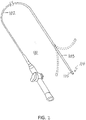
- FIG. 1 is a schematic illustration of an invasive medical procedure using apparatus 12, according to an embodiment of the present invention.
- the procedure is performed by a medical professional 14, and, by way of example, the procedure in the description hereinbelow is assumed to comprise ablation of a portion of a myocardium 16 of the heart of a human patient 18.
- embodiments of the present invention are not merely applicable to this specific procedure, and may include substantially any procedure on biological tissue or on non-biological materials.
- medical professional 14 inserts a probe 20 into a sheath 21 that has been pre-positioned in a lumen of the patient.
- Sheath 21 is positioned so that a distal end 22 of probe 20 enters the heart of the patient.
- a catheter 24, which is described in more detail below, is deployed through a lumen 23 of the probe 20, and exits from a distal end of the probe 20.
- apparatus 12 is controlled by a system processor 46, which is located in an operating console 15 of the apparatus.
- Console 15 comprises controls 49 which are used by professional 14 to communicate with the processor.
- the processor 46 typically tracks a location and an orientation of the distal end 22 of the probe 20, using any method known in the art.
- processor 46 may use a magnetic tracking method, wherein magnetic field generators 25X, 25Y and 25Z external to the patient 18 generate signals in coils positioned in the distal end of the probe 20.
- the software for the processor 46 may be downloaded to the processor in electronic form, over a network, for example. Alternatively or additionally, the software may be provided on non-transitory tangible media, such as optical, magnetic, or electronic storage media.
- the tracking of the distal end 22 is typically displayed on a three-dimensional representation 60 of the heart of the patient 18 on a screen 62.
- the processor 46 communicates with a memory 50, which has a number of modules used by the processor to operate the apparatus.
- the memory 50 comprises a temperature module 52, an ablation module 54, and an electrocardiograph (ECG) module 56.
- the memory 50 typically comprises other modules, such as a force sensor module 53, with a voltage source 51, for sensing the force on the distal end 22.
- the memory 50 may also include a tracking module 55 for operating the tracking method used by the processor 46, and an irrigation module 57 allowing the processor to control irrigation provided for the distal end 22.
- the modules may comprise hardware as well as software elements.
- FIG. 2 is a schematic perspective view of a catheter 100 suitable for use with the aforementioned apparatus 12.
- the catheter 100 has an elongated catheter body 102, a deflection section 103 and a distal section 104 which includes a distal tip electrode 105.
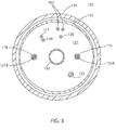
- the catheter body 102 has an outer wall 120 with a central lumen 121, which may be lined with a stiffener tubing 122, as shown in FIG. 3 .
- Various components pass through the lumen 121, including, for example, lead wires 130 for the tip electrode 105 and any ring electrodes (not shown), a pair of deflection puller wires (or tensile members) 131A, 131B, an irrigation tubing 132, a cable 133 for an EM position sensor (not shown) housed in the distal section 104, thermocouple wire or wire pair 151/153, and any other cables or wires.
- the deflection section 103 includes a shorter section of multi-lumened tubing 110 with multiple lumens.
- the lumens include, for example, a first lumen 111 for the lead wires 130 and thermocouple wire or wire pair 151/153, a second lumen 112 for the first puller wire 131A, a third lumen 113 for the cable 133, a fourth lumen 114 for the second puller wire 131B, and a fifth lumen 115 for the irrigation tubing 132.
- the size, shape and location of the lumens are not critical, except that the second and fourth lumens 122 and 124 may be off-axis and diametrically opposed for effective bi-directional deflection of the deflection section 103.
- portions of the puller wires 131A, 131B extending through the catheter body 102 are surrounded by respective compression coils 116 which generally limit deflection curvature of the catheter to the multi-lumened tubing 110 of the deflection section 103, distal of the catheter body 102.
- Portions of the puller wires 131A, 131B distal of the catheter body 102 are surrounded by respective protective sheaths 117 which prevent the puller wires from cutting into the side wall of the multi-lumened tubing 110 when the deflection section 103 is deflected.
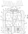
- the tip electrode 105 of the distal section 104 has a shell 106 and a plug 107 defining an interior chamber 109 through which irrigation fluid enters the interior chamber 109 via a distal end section of the irrigation tubing 132 that passes through the plug 107 via a through-hole 108.
- a distal end of lead wire 130 for tip electrode 105 terminates in a blind hole 123 formed in a proximal face of the plug 107.
- Distal ends of thermocouple wire(s) 151 terminate in a blind hole 124 formed in the proximal face of the plug 107.
- a capacitive force sensor 136 is provided to sense the application of a force, including a force with any normal component, on the distal wall 135, for example, when the distal wall 135 comes into contact with tissue surface 128 (see FIG. 5B ).
- the capacitive force sensor 136 is situated in a recess 140 formed in the distal wall 135, for example, by stamping (solid line) or shallow boring (broken line), and has two conductive plates 137, 138 and a dieletric 139 in between. It is understood that the recess 140 may also be formed in a circumferential sidewall 126 of the shell 106 for tissue contact when the distal section 104 lays against tissue and is dragged along the tissue surface.
- the plates are of similar construction in shape and size and are generally parallel to each other. With the plates 137 and 138 separated from each other by a distance D when the capacitive force sensor 136 is in its neutral state, the capacitive force sensor 136 has a thickness T while in its neutral state, free from any forces or contact.
- the dielectric has an elastic structure allowing deformation, including compression between the plates when the capacitive force sensor 136 is subjected to a force with a vector component perpendicular to the distal wall 135 of the tip shell 106.
- the capacitance of the force sensor 136 changes when the distance between the plates 137 and 138 changes. In particular, the capacitance of the force sensor 136 increases when the distance between the plates decreases.
- the inner plate 137 is affixed to surface 134 in the recess 140, for example, by adhesive 141, and in some embodiments, the plates 137 and 138 are generally parallel to the distal wall 135.
- the depth of the recess 140 is less than the thickness T of the capacitive force sensor 136 in its neutral state so that the outer plate 138 is projected out in front of the distal wall 135 and is exposed so that it can be pressed toward the plate 137 upon contact with the tissue surface 128 when the catheter is advanced toward the tissue surface for mapping and/or ablation.
- the first plate 137 is connected to a first terminal 117 and the second plate is connected to a second terminal 118, each of which may take the form of a lead wire that passes through respective apertures 127 and 129 formed in the distal wall 135 of the shell 106.
- the terminals 117 and 118 appropriately protected by insulating sheaths (not shown), extend through the interior chamber 109 and a common or different through-hole(s) 119 formed in the plug 107 ( see FIG. 5C ).
- a short, single-lumened connector tubing 144 extends between the distal end of the multi-lumened tubing 110 and the tip electrode 105, to allow components to reorient as needed between their respective lumen and their respective blind holes or through-holes in the plug 107 of the tip electrode 105.
- the capacitance of the force sensor 136 is measured by the force sensing module 53 of the operating console (see FIG. 1 ).
- a voltage is applied across the capacitive force sensor 136 by the voltage source 51 of the force sensing module 53 via the terminals 117, 118.
- the capacitance for the force sensor 136 in the neutral state with the plates 137 and 138 separated by a distance D (see FIG. 5A ) is measured by the force sensing module 53 as C.
- the tissue surface 128 contacts protruding outer plate 138 and exerts a force with a normal force component N which compresses the dielectric 139 changing the separation distance from D to D1 (see FIG.
- D1 ⁇ D which changes the capacitance of the force sensor 136 from C to C1, where C1 > C.
- the force sensing module 53 detects the increase capacitance C1 and, for example, responds by providing an indicia to the medical professional 14, such as activating an audio signal and/or a visual signal.
- the measured capacitance remains at C1 so long as the normal force component N remains.
- the separation distance decreases further to D2 where D2 ⁇ D1 ⁇ D and the measured capacitance increases correspondingly to C2, where C2 > C1 > C.
- the separation distance increases to D3 where D1 ⁇ D3 ⁇ D
- the measured capacitance decreases correspondingly to C3, where C1 > C3 > C.
- the change in the capacitance output of the force sensor 136 from C1 to C3 is detected and measured by the force sensor 136 which advantageously indicates the change in force applied to the tip electrode 105 that is reflective of the change in tissue contact between the tip electrode and tissue surface, for example, by changing the audio signal and/or the visual signal.
- the terminals 117 and 118 are connected to electrical extensions (e.g., embedded lead wires, not shown) of a flex circuit 145 that is affixed to the outer surface 134 of the shell 106, as shown in FIG. 6 .
- the flex circuit 145 or the embedded lead wires pass through one or more sealed through-holes 146 formed in the sidewall of the connector tubing 144 to enter into the lumen of the connector tubing 144 and proximally into an appropriate lumen of the multi-lumened tubing 110.
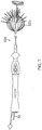
- a catheter 224 has a distal inflatable member or balloon 280, as shown in FIG. 7 in an inflated deployed configuration.
- the balloon 280 is used to ablate an ostium 211 of a lumen, such as a pulmonary vein 213.
- the inflatable balloon 280 of the catheter 224 has an exterior wall or membrane 226 of a bio-compatible material, for example, formed from a plastic such as polyethylene terephthalate (PET), polyurethane or PEBAX®.
- PET polyethylene terephthalate
- PEBAX® polyurethane
- the membrane 226 of the balloon 280 is formed with irrigation pores or apertures 227 through which the fluid can exit from the interior of the balloon 280 to outside the balloon for cooling the tissue ablation site at the ostium. While FIG. 7 shows fluid exiting the balloon as jet streams, it is understood that the fluid may exit the balloon with any desired flow rate and/or pressure, including a rate where the fluid is seeping out of the balloon.
- a suitable balloon is described in U.S. Application Serial No. 15/360966, filed November 23, 2016 , the entire disclosure of which is incorporated herein by reference.
- the membrane 226 supports and carries a combined electrode and temperature sensing member which is constructed as a multi-layer flexible circuit electrode assembly 284.
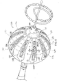
- the "flex circuit electrode assembly" 284 may have many different geometric configurations. In the illustrated embodiment of FIG. 8 , the flex circuit electrode assembly 284 has a plurality of strips 230. The leaves 230 are generally evenly distributed about the distal end 288 and the balloon 280. One or more contact electrodes 233 on each leaf come into galvanic contract with the ostium 211 during an ablation procedure, during which electrical current flows from the contact electrodes 233 to the ostium 211 to form lesions 231.
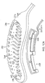
- the flex circuit electrode assembly 284 is described with respect to one of its leaf 230 as shown in FIG. 9 , although it is understood that following description may apply to each leaf of the assembly.
- the flex circuit electrode assembly 284 includes a flexible and resilient sheet substrate 234, constructed of a suitable bio-compatible materials, for example, polyimide.
- the sheet substrate 234 has a greater heat resistance (or a higher melting temperature) compared to that of the balloon membrane 226.
- the substrate 234 is constructed of a thermoset material having a decomposition temperature that is higher than the melting temperature of the balloon membrane 226 by approximately 100C or more.
- the substrate 234 is formed with one or more irrigation pores or apertures 235 that are in alignment with the irrigation apertures 235 of the balloon membrane 226 so that fluid in the interior of the balloon can pass through the irrigation apertures 235 and exit the balloon to the ablation sites on the ostium.
- the substrate 234 has a first or outer surface 236 facing away from the balloon membrane 226, and a second or inner surface 237 facing the balloon membrane 226. On its outer surface 236, the substrate 234 supports and carries the contact electrodes 233 adapted for tissue contact with the ostium. On its inner surface 237, the substrate 234 supports and carries a wiring electrode 238.
- the contact electrode 233 delivers RF energy to the ostium during ablation and/or is connected to a thermocouple junction for temperature sensing of the ostium.
- the contact electrode 233 has a longitudinally elongated portion 240 and a plurality of thin transversal linear portions or fingers 241 extending generally perpendicularly from each lateral side of the elongated portion 240 between enlarged proximal and distal ends 242P and 242D, generally evenly spaced therebetween.
- the elongated portion 240 has a greater width and each of the fingers has a generally uniform lesser width.
- the configuration or trace of the contact electrode 233 resembles a "fishbone.”
- the fingers 241 of the contact electrode 233 advantageously increase the circumferential or equatorial contact surface of the contact electrode 233 with the ostium while void regions 243 between adjacent fingers 241 advantageously allow the balloon 280 to collapse inwardly and/or expand radially as needed at locations along its equator.
- the fingers 241 have different lengths, some being longer, others being shorter
- the plurality of fingers include a distal finger, a proximal finger and fingers therebetween, where each of the fingers in between has a shorter adjacent finger.
- each finger has a length different from its distal and/or proximal immediately adjacent neighboring finger(s) such that the length of each finger generally follows the tapered configuration of each leaf 230.
- there are 222 fingers extending across (past each lateral side of) the elongated portion 240, with the longest finger being the third finger from the enlarged proximal end 242P.
- the contact electrode 233 includes gold 258B with a seed layer 245, between the gold 258B and the membrane 226 (see FIG. 10A and FIG. 10B ).
- the seed layer may include titanium, tungsten, palladium, silver, and/or combinations thereof.
- exclusion zone 247 Formed within the contact electrode 233 are one or more exclusion zone 247, each surrounding an irrigation aperture 227 formed in the substrate 234.
- the exclusion zones 247 are voids purposefully formed in the contact electrode 233, as explained in detail further below, so as to avoid damage to the contact electrode 233 during construction of the electrode assembly 284 in accommodating the irrigation apertures 227 at their locations and in their function.
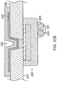
- conductive blind vias 248 are conductive or metallic formations that extend through through-holes (not shown) in the substrate 234 and are configured as electrical conduits connecting the contact electrode 233 on the outer surface 236 and the wiring electrode 238 on the inner surface 237. It is understood that “conductive” is used herein interchangeably with “metallic” in all relevant instances.
- the wiring electrode 238 is generally configured as an elongated body generally similar in shape and size to the elongated portion 240 of the contact electrode 233.
- the wiring electrode 238 loosely resembles a "spine" and also functions as a spine in terms of providing a predetermined degree of longitudinal rigidity to each leaf 230 of the electrode assembly 284.
- the wiring electrode 238 is positioned such that each of the blind vias 248 is in conductive contact with both the contact electrode 233 and the wiring electrode 238.
- the two electrodes 233 and 238 are in longitudinal alignment with other, with all nine blind vias 248 in conductive contact with both electrodes 233 and 238.
- the wiring electrode 238 has an inner portion of copper and an outer portion of gold.
- the wiring electrode 238 is also formed with its exclusion zones 259 around the irrigation apertures 235 in the substrate 234.
- the wiring electrode 238 is further formed with solder pad portions 261, at least one active 261A, and there may be one or more inactive solder pad portions 261B.
- the solder pad portions 261A and 261B are extensions from a lateral side of the elongated body of the wiring electrode 238.
- an active solder pad portion 261A is formed at about a mid-location along the elongated body, and a respective inactive solder pad portion 261B is provided at each of the enlarged distal end 242D and the enlarged proximal end 242P.
- Attached, e.g., by a solder weld 263, to the active solder pad portion 261A are the wire pair, e.g., a constantan wire 251 and a copper wire 253.
- the copper wire 253 provides a lead wire to the wiring electrode 233, and the copper wire 253 and the constantan wire 251 provide a thermocouple whose junction is at solder weld 263.
- the wire pair 251/253 are passed through a through-hole 229 formed in the membrane 226 into the interior of the balloon 280.
- the wire pair 251/253 may run between the membrane 226 and the substrate 234 and further proximally between the membrane 226 and a proximal tail 230P until the wire pair 251/253 enters the tubular shaft 270 via a through-hole (not shown) formed in the tubular shaft sidewall near its distal end.
- the flex circuit electrode assembly 284, including the leaves 230 and the tail 230P, is affixed to the balloon membrane 226 such that the outer surface 236 of the substrate 234 is exposed and the inner surface 237 of the substrate 234 is affixed to the balloon membrane 226, with the wiring electrode 238 and wire pair 251/253 sandwiched between the substrate 234 and the balloon membrane 226.
- the irrigation apertures 235 in the substrate 234 are aligned with the irrigation apertures 227 in the balloon membrane 226.
- the exclusion zones 259 in the wiring electrode 238 and the exclusion zones 247 in the contact electrode 233 are concentrically aligned with each other, as well as with the irrigation apertures 227 and 235.
- one or more substrates 234 of the balloon 280 each include at least one capacitive force sensor 136 strategically positioned at predetermined locations between the equator and the distal end of the balloon 280, for example, generally along one or more latitudes, e.g., L1, L2 and L3, of the balloon 280 as shown in FIG. 8 , for circumferential contact with an ostium or tubular region.
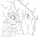
- a capacitive force sensor 136 with plates 137 and 138 and a dielectric 139 therebetween, may be positioned generally along a latitude L1 distal of each contact electrode 233, as shown in FIG. 11 .
- each capacitive force sensor 136 has its plate 138 affixed to the outer surface 234 of the membrane 226, situated within a through-hole 228 formed in the respective substrates 234 of the contact electrodes 233. (In some embodiments, the plate 138 may be affixed to the membrane 226.) Terminals 117 and 118 for each respective capacitive force sensor 136 are each connected to a respective full via 248F that includes conductive formation that extends through a through-hole (not shown) in the respective substrates 234 and the membrane 226 to connect to respective lead wires 267 and 268, respectively, that extend into the interior of the balloon 280 and toward the proximal end of the balloon and through the shaft 270.
- the lead wires may be included in a ribbon cable that extends through the interior of the balloon 280.
- capacitive force sensor 136 (shown in broken lines in FIG. 11 ) may be provided within an exclusion zone 247' formed in the contact electrode 233.
- one or more capacitive force sensors 136A are affixed at predetermined locations X on the membrane 226 along one or more latitudes, with the plates 138 affixed to the membrane 226, as shown in FIG. 11 .
- Terminals 117 and 118 for each respective capacitive force sensor 136 are each passed through a respective through-hole formed in the membrane 226, sealed by plugs 250, into the interior of the balloon 280 toward the proximal end of the balloon and through the shaft 270.
- lead wires 267 and 268 may be connected to terminals 117 and 118, respectively, in the interior of the balloon 280.
- the dielectric 139 between the plates 137 and 138 may be air, and that an elastic spring member 148, e.g., wave spring, may be situated between the plates ( FIG. 12 ) to support the plates at a separation distance D therebetween, where the spring member 148 is elastically compressible to allow the separation distance D to decrease when a contact force is applied to the plates upon tissue contact.
- an elastic spring member 148 e.g., wave spring
- the capacitive force sensor are formed by 3-D printing, including 3-D printing directly onto the catheter distal tip surface on which the sensor is carried on the catheter, and that 3-D printing may be used to form the plates, as well as any mechanical spring for separating and support the plates.
- the capacitance of the force sensor 136 is measured by the force sensing module 53 (see FIG. 1 ).
- the capacitance for the force sensor 136 in the neutral state with the plates 237 and 238 separated by a distance D is measured by the force sensing module 53 as C.
- a distal circumferential portion of the balloon comes into contact with the ostium which exerts a force with a normal force component N that compresses the dielectric 239 changing the separation distance from D to D1, where D1 ⁇ D, which changes the capacitance of the force sensor 136 from C to C1, where C1 > C.
- the force sensing module 53 detects the increase capacitance C1 and, for example, responds by providing an indicia to the medical professional 14, such as sounding an audio signal or a visual signal.
- the measured capacitance remains at C1 so long as the normal force component N remains.
- the separation distance decreases further to D2 where D2 ⁇ D1 ⁇ D and the measured capacitance increases correspondingly to C2, where C2 > C1 > C.
- the change in the capacitance output of the force sensors 236 detected and measured by the force sensors 236 advantageously indicates the change in force applied to the tip electrode 105 reflective of the change in tissue contact between the balloon and the ostium.
- Different readings or different changes in readings by the force sensing module of the capacitive force sensors along one or more latitudes of the balloon can indicate the angle of contact, e.g., off-axis tilt angle of the longitudinal axis of the balloon relative to the longitudinal axis of the ostium.
- the angle of contact e.g., off-axis tilt angle of the longitudinal axis of the balloon relative to the longitudinal axis of the ostium.
Landscapes
- Health & Medical Sciences (AREA)
- Life Sciences & Earth Sciences (AREA)
- Surgery (AREA)
- Engineering & Computer Science (AREA)
- Heart & Thoracic Surgery (AREA)
- Veterinary Medicine (AREA)
- Biomedical Technology (AREA)
- Animal Behavior & Ethology (AREA)
- General Health & Medical Sciences (AREA)
- Public Health (AREA)
- Medical Informatics (AREA)
- Molecular Biology (AREA)
- Physics & Mathematics (AREA)
- Biophysics (AREA)
- Pathology (AREA)
- Nuclear Medicine, Radiotherapy & Molecular Imaging (AREA)
- Otolaryngology (AREA)
- Plasma & Fusion (AREA)
- Cardiology (AREA)
- Anesthesiology (AREA)
- Hematology (AREA)
- Child & Adolescent Psychology (AREA)
- Pulmonology (AREA)
- Oral & Maxillofacial Surgery (AREA)
- Robotics (AREA)
- General Physics & Mathematics (AREA)
- Physiology (AREA)
- Surgical Instruments (AREA)
- Media Introduction/Drainage Providing Device (AREA)
- Measurement And Recording Of Electrical Phenomena And Electrical Characteristics Of The Living Body (AREA)
- Measuring And Recording Apparatus For Diagnosis (AREA)
Abstract
Description
- This invention relates to medical devices. More particularly, this invention relates to improvements in cardiac catheterization, including electrophysiologic (EP) catheters, in particular, EP catheters for mapping and/or ablating ostia and tubular regions in the heart.
- Cardiac arrhythmias, such as atrial fibrillation, occur when regions of cardiac tissue abnormally conduct electric signals to adjacent tissue, thereby disrupting the normal cardiac cycle and causing asynchronous rhythm.
- Procedures for treating arrhythmia include surgically disrupting the origin of the signals causing the arrhythmia, as well as disrupting the conducting pathway for such signals. By selectively ablating cardiac tissue by application of energy via a catheter, it is sometimes possible to cease or modify the propagation of unwanted electrical signals from one portion of the heart to another. The ablation process destroys the unwanted electrical pathways by formation of non-conducting lesions.
- Circumferential lesions at or near the ostia of the pulmonary veins have been created to treat atrial arrhythmias.
U.S. Pat. Nos. 6,012,457 and6,024,740, both to Lesh , disclose a radially expandable ablation device, which includes a radiofrequency electrode. Using this device, it is proposed to deliver radiofrequency energy to the pulmonary veins in order to establish a circumferential conduction block, thereby electrically isolating the pulmonary veins from the left atrium. -
U.S. Pat. No. 6,814,733 to Schwartz et al. , which is commonly assigned herewith and herein incorporated by reference, describes a catheter introduction apparatus having a radially expandable helical coil as a radiofrequency emitter. In one application the emitter is introduced percutaneously, and transseptally advanced to the ostium of a pulmonary vein. The emitter is radially expanded, which can be accomplished by inflating an anchoring balloon about which the emitter is wrapped, in order to cause the emitter to make circumferential contact with the inner wall of the pulmonary vein. The coil is energized by a radiofrequency generator, and a circumferential ablation lesion is produced in the myocardial sleeve of the pulmonary vein, which effectively blocks electrical propagation between the pulmonary vein and the left atrium. - Another example is found in
U.S. Pat. No. 7,340,307 to Maguire, et al. , which proposes a tissue ablation system and method that treats atrial arrhythmia by ablating a circumferential region of tissue at a location where a pulmonary vein extends from an atrium. The system includes a circumferential ablation member with an ablation element and includes a delivery assembly for delivering the ablation member to the location. The circumferential ablation member is generally adjustable between different configurations to allow both the delivery through a delivery sheath into the atrium and the ablative coupling between the ablation element and the circumferential region of tissue. - More recently, inflatable catheter electrode assemblies have been constructed with flex circuits to provide the outer surface of the inflatable electrode assemblies with a multitude of very small electrodes. Examples of catheter balloon structures are described in
U.S. Publication No. 2016/0175041 , titled Balloon for Ablation Around Pulmonary Vein, the entire content of which is incorporated herein by reference. - Flex circuits or flexible electronics involve a technology for assembling electronic circuits by mounting electronic devices on flexible plastic substrates, such as polyimide, Liquid Crystal Polymer (LCP), PEEK or transparent conductive polyester film (PET). Additionally, flex circuits can be screen printed silver circuits on polyester. Flexible printed circuits (FPC) are made with a photolithographic technology. An alternative way of making flexible foil circuits or flexible flat cables (FFCs) is laminating very thin (0.07 mm) copper strips in between two layers of PET. These PET layers, typically 0.05 mm thick, are coated with an adhesive which is thermosetting, and will be activated during the lamination process. Single-sided flexible circuits have a single conductor layer made of either a metal or conductive (metal filled) polymer on a flexible dielectric film. Component termination features are accessible only from one side. Holes may be formed in the base film to allow component leads to pass through for interconnection, normally by soldering.
- Because the quality of a lesion depends on a number of factors, including size and depth, the force at which an electrode contacts tissue is a useful to a medical professional when ablating tissue. And because an ablating electrode has many possible configurations, including a tip electrode, a ring electrode or an electrode on a balloon, a force sensor should be adaptable for use with any such electrodes, so that force can be measured whether tissue contact occurs at a catheter's distal tip as a point contact on tissue or its side while being dragged along tissue, or even simultaneously at multiple tissue surface locations circumferentially within an ostium or tubular region.'
- Accordingly, there is a desire for a catheter having an electrode with a force sensor that is configured for measuring a force applied by the electrode against tissue surface. And because a capacitive tactile sensor is reliably responsive to the an applied force and can be manufactured in very small sizes, an electrode having a capacitive force sensor can reliably measure an applied force whether the electrode is configured as a tip electrode, a ring electrode or even as an electrode on a balloon catheter.
- The present invention is directed to an electrophysiology catheter with a micro capacitive tactile sensor provided in the distal section where tissue contact occurs, wherein the distal section may include a tip electrode, a ring electrode and/or a balloon catheter. The capacitive sensor is configured to exhibit a change in capacitance upon touching tissue and during tissue contact wherein the force applied with tissue contact is measured and reliably calibrated in assessing and determining the applied force.
- In some embodiments, the catheter has an elongated catheter shaft, a distal tip electrode having a shell configured for contact with tissue and a capacitive force sensor having a first plate affixed to the shell, a second plate distal of the first plate and configured for contact with the tissue, and an elastically compressible dielectric between the first and second plates, wherein the force sensor has a first capacitance when the first and second plates are separated by a first distance, and the force sensor has a second capacitance when the first and second plates are separated by a second different from the first distance. The catheter also includes a first terminal connected to the first plate, and a second terminal connected to the second plate.
- In some embodiments, the first and second plates are parallel to each other.
- In some embodiments, the first and second plates are generally of the same size and shape.
- In some embodiments, the capacitive force sensor is affixed to a distal face of the shell.
- In some embodiments, the first plate protrudes above an outer surface of the shell.
- In some embodiment, the shell has a recess and the capacitive force sensor is situated in the recess with at least the first plate exposed.
- In some embodiments, the recess is formed in a distal face of the shell.
- In some embodiments, the recess is formed in a circumferential wall of the shell.
- In some embodiments, the first terminal passes through a first through-hole formed in the shell.
- In some embodiments, the second terminal passes through a second through-hole formed in the shell.
- In some embodiments, the first terminal extends along an outer surface of the shell.
- In some embodiments, an electrophysiology catheter adapted for use in an ostium, includes a balloon having an membrane and configured with a distal end and a proximal end defining a longitudinal axis and at least one circumferential latitude, and a micro capacitive force sensor having a first plate on the balloon, a second plate configured for contact with the tissue, and an elastically compressible dielectric between the first and second plates, wherein the force sensor has a first capacitance when the first and second plates are separated by a first distance, and the force sensor has a second capacitance when the first and second plates are separated by a second different from the first distance. The catheter also has a first terminal connected to the first plate, and a second terminal connected to the second plate.
- In some embodiments, the first plate is affixed to the membrane.
- In some embodiments, the catheter also includes a contact electrode and the first plate is affixed to the contact electrode.
- In some embodiments, the contact electrode is configured with an elongated body and a plurality of transverse members.
- In some embodiments, the catheter also includes a first via through the membrane, wherein the first terminal is connected to the first via.
- In some embodiments, the catheter also includes a second via through the membrane, the second terminal connected to the second via.
- In some embodiments, the catheter includes a plurality of capacitive force sensors arranged along a circumferential latitude of the balloon.
- In some embodiments, an electrophysiology catheter system having a catheter having a capacitive force sensor with has a first plate, a second plate, and a dielectric therebetween, and a processor having a memory device and a voltage source. The catheter also includes a first terminal connected to the first plate and the voltage source, and a second terminal connected to the second plate and the voltage source, wherein the memory device is configured to store instructions that, when executed by the processor, causes the processor to: actuate the voltage source, determine a capacitance across the capacitive force sensor, and detect a change in the capacitance.
- In some embodiments, the capacitive force sensor has a first capacitance when the first and second plates are separated by a first distance, and the capacitive force sensor has a second capacitance when the first and second plates are separated by a second distance, and the processor is configured to detect the change in capacitance between the first and second capacitance.
- In some embodiments, the dielectric is compressible.
- In some embodiments, the dielectric is elastically compressible.
- In some embodiments, the capacitive force sensor is positioned on a distal portion of the catheter configured for tissue contact.
- These and other features and advantages of the present invention will be better understood by reference to the following detailed description when considered in conjunction with the accompanying drawings. It is understood that selected structures and features have not been shown in certain drawings so as to provide better viewing of the remaining structures and features.
-
FIG. 1 is a schematic illustration of a medical procedure, according to an embodiment of the present invention. -
FIG. 2 is a perspective view of a catheter suitable for use in the medical procedure ofFIG. 1 , according to an embodiment of the present invention. -
FIG. 3 is an end cross-sectional view of a catheter body of the catheter ofFIG. 2 . -
FIG. 4 is an end cross-sectional view of a deflection section of the catheter ofFIG. 2 . -
FIG. 5A is side cross-sectional view of a distal section of the catheter ofFIG. 2 , including a distal tip electrode with a capacitive force sensor in a neutral configuration. -
FIG. 5B is a detailed cross-sectional view of the capacitive force sensor ofFIG. 5A in a tissue contact or compressed configuration. -
FIG. 5C is an end cross-sectional view of a proximal end of the distal tip electrode ofFIG. 5A , taken along line C-C. -
FIG. 6 is a side cross-sectional view of a distal section of a catheter, in accordance with another embodiment of the present invention. -
FIG. 7 is a top plan view of a balloon catheter suitable for use in the medical procedure ofFIG. 1 , according to another embodiment of the present invention. -
FIG. 8 is a perspective view of a balloon of the balloon catheter ofFIG. 7 , along with a lasso catheter inserted therethrough. -
FIG. 9 is a perspective view of a flexible circuit electrode assembly partially lifted off the balloon to reveal its underside and related elements, according to an embodiment of the present invention. -
FIG. 10A is an exploded view of a flexible circuit electrode assembly during a stage of construction, according to an embodiment of the present invention. -
FIG. 10B is a side cross-sectional view of a via formed in a balloon membrane, according to an embodiment of the present invention. -
FIG. 11 is a detailed perspective view of a balloon membrane with capacitive force sensors, according to an embodiment of the present invention. -
FIG. 12 is a detailed, exploded perspective view of a capacitive force sensor, according to another embodiment of the present invention. - In the following description, like elements in the drawings are identified by like numerals, and like elements are differentiated as necessary by appending a letter to the identifying numeral.
-
FIG. 1 is a schematic illustration of an invasive medicalprocedure using apparatus 12, according to an embodiment of the present invention. The procedure is performed by a medical professional 14, and, by way of example, the procedure in the description hereinbelow is assumed to comprise ablation of a portion of amyocardium 16 of the heart of ahuman patient 18. However, it is understood that embodiments of the present invention are not merely applicable to this specific procedure, and may include substantially any procedure on biological tissue or on non-biological materials. - In order to perform the ablation, medical professional 14 inserts a
probe 20 into asheath 21 that has been pre-positioned in a lumen of the patient.Sheath 21 is positioned so that adistal end 22 ofprobe 20 enters the heart of the patient. Acatheter 24, which is described in more detail below, is deployed through alumen 23 of theprobe 20, and exits from a distal end of theprobe 20. - As shown in
FIG. 1 ,apparatus 12 is controlled by asystem processor 46, which is located in an operatingconsole 15 of the apparatus.Console 15 comprisescontrols 49 which are used by professional 14 to communicate with the processor. During the procedure, theprocessor 46 typically tracks a location and an orientation of thedistal end 22 of theprobe 20, using any method known in the art. For example,processor 46 may use a magnetic tracking method, wherein magnetic field generators 25X, 25Y and 25Z external to the patient 18 generate signals in coils positioned in the distal end of theprobe 20. The CARTO® available from Biosense Webster, Inc. of Diamond Bar, California, uses such a tracking method. - The software for the
processor 46 may be downloaded to the processor in electronic form, over a network, for example. Alternatively or additionally, the software may be provided on non-transitory tangible media, such as optical, magnetic, or electronic storage media. The tracking of thedistal end 22 is typically displayed on a three-dimensional representation 60 of the heart of the patient 18 on ascreen 62. - In order to operate
apparatus 12, theprocessor 46 communicates with amemory 50, which has a number of modules used by the processor to operate the apparatus. Thus, thememory 50 comprises atemperature module 52, anablation module 54, and an electrocardiograph (ECG)module 56. Thememory 50 typically comprises other modules, such as a force sensor module 53, with avoltage source 51, for sensing the force on thedistal end 22. Thememory 50 may also include a tracking module 55 for operating the tracking method used by theprocessor 46, and an irrigation module 57 allowing the processor to control irrigation provided for thedistal end 22. The modules may comprise hardware as well as software elements. -
FIG. 2 is a schematic perspective view of acatheter 100 suitable for use with theaforementioned apparatus 12. Thecatheter 100 has anelongated catheter body 102, adeflection section 103 and adistal section 104 which includes adistal tip electrode 105. As understood in the art, in some embodiments, thecatheter body 102 has anouter wall 120 with acentral lumen 121, which may be lined with astiffener tubing 122, as shown inFIG. 3 . Various components pass through thelumen 121, including, for example,lead wires 130 for thetip electrode 105 and any ring electrodes (not shown), a pair of deflection puller wires (or tensile members) 131A, 131B, anirrigation tubing 132, acable 133 for an EM position sensor (not shown) housed in thedistal section 104, thermocouple wire orwire pair 151/153, and any other cables or wires. - As understood in the art, in some embodiments, the
deflection section 103 includes a shorter section of multi-lumened tubing 110 with multiple lumens. As shown inFIG. 4 , the lumens include, for example, afirst lumen 111 for thelead wires 130 and thermocouple wire orwire pair 151/153, asecond lumen 112 for thefirst puller wire 131A, athird lumen 113 for thecable 133, afourth lumen 114 for thesecond puller wire 131B, and afifth lumen 115 for theirrigation tubing 132. The size, shape and location of the lumens are not critical, except that the second andfourth lumens deflection section 103. As understood in the art, portions of thepuller wires catheter body 102 are surrounded by respective compression coils 116 which generally limit deflection curvature of the catheter to the multi-lumened tubing 110 of thedeflection section 103, distal of thecatheter body 102. Portions of thepuller wires catheter body 102 are surrounded by respectiveprotective sheaths 117 which prevent the puller wires from cutting into the side wall of the multi-lumened tubing 110 when thedeflection section 103 is deflected. - As shown in
FIG 5A . thetip electrode 105 of thedistal section 104 has ashell 106 and aplug 107 defining aninterior chamber 109 through which irrigation fluid enters theinterior chamber 109 via a distal end section of theirrigation tubing 132 that passes through theplug 107 via a through-hole 108. A distal end oflead wire 130 fortip electrode 105 terminates in ablind hole 123 formed in a proximal face of theplug 107. Distal ends of thermocouple wire(s) 151 terminate in ablind hole 124 formed in the proximal face of theplug 107. - On an
outer surface 134 of adistal wall 135 of theshell 106, acapacitive force sensor 136 is provided to sense the application of a force, including a force with any normal component, on thedistal wall 135, for example, when thedistal wall 135 comes into contact with tissue surface 128 (seeFIG. 5B ). Thecapacitive force sensor 136 is situated in arecess 140 formed in thedistal wall 135, for example, by stamping (solid line) or shallow boring (broken line), and has twoconductive plates recess 140 may also be formed in acircumferential sidewall 126 of theshell 106 for tissue contact when thedistal section 104 lays against tissue and is dragged along the tissue surface. - In some embodiments, the plates are of similar construction in shape and size and are generally parallel to each other. With the
plates capacitive force sensor 136 is in its neutral state, thecapacitive force sensor 136 has a thickness T while in its neutral state, free from any forces or contact. However, the dielectric has an elastic structure allowing deformation, including compression between the plates when thecapacitive force sensor 136 is subjected to a force with a vector component perpendicular to thedistal wall 135 of thetip shell 106. Advantageously, the capacitance of theforce sensor 136 changes when the distance between theplates force sensor 136 increases when the distance between the plates decreases. - As shown in
FIG. 5A , theinner plate 137 is affixed to surface 134 in therecess 140, for example, by adhesive 141, and in some embodiments, theplates distal wall 135. The depth of therecess 140 is less than the thickness T of thecapacitive force sensor 136 in its neutral state so that theouter plate 138 is projected out in front of thedistal wall 135 and is exposed so that it can be pressed toward theplate 137 upon contact with thetissue surface 128 when the catheter is advanced toward the tissue surface for mapping and/or ablation. - The
first plate 137 is connected to afirst terminal 117 and the second plate is connected to asecond terminal 118, each of which may take the form of a lead wire that passes throughrespective apertures distal wall 135 of theshell 106. Theterminals interior chamber 109 and a common or different through-hole(s) 119 formed in the plug 107 (seeFIG. 5C ). In some embodiments, a short, single-lumened connector tubing 144 extends between the distal end of the multi-lumened tubing 110 and thetip electrode 105, to allow components to reorient as needed between their respective lumen and their respective blind holes or through-holes in theplug 107 of thetip electrode 105. - In use, the capacitance of the
force sensor 136 is measured by the force sensing module 53 of the operating console (seeFIG. 1 ). A voltage is applied across thecapacitive force sensor 136 by thevoltage source 51 of the force sensing module 53 via theterminals force sensor 136 in the neutral state with theplates FIG. 5A ) is measured by the force sensing module 53 as C. When thetip electrode 105 approaches tissue, thetissue surface 128 contacts protrudingouter plate 138 and exerts a force with a normal force component N which compresses the dielectric 139 changing the separation distance from D to D1 (seeFIG. 5B ), where D1 < D, which changes the capacitance of theforce sensor 136 from C to C1, where C1 > C. The force sensing module 53 detects the increase capacitance C1 and, for example, responds by providing an indicia to the medical professional 14, such as activating an audio signal and/or a visual signal. The measured capacitance remains at C1 so long as the normal force component N remains. Where the normal force component increases (such as where the medical professional further presses the distal tip electrode into the tissue surface), the separation distance decreases further to D2 where D2 < D1 < D and the measured capacitance increases correspondingly to C2, where C2 > C1 > C. Where the normal force component decreases (such as where the medical professional begins to retract the distal trip electrode from the tissue surface, the separation distance increases to D3 where D1 < D3 < D, and the measured capacitance decreases correspondingly to C3, where C1 > C3 > C. In this manner, the change in the capacitance output of theforce sensor 136 from C1 to C3 is detected and measured by theforce sensor 136 which advantageously indicates the change in force applied to thetip electrode 105 that is reflective of the change in tissue contact between the tip electrode and tissue surface, for example, by changing the audio signal and/or the visual signal. - In some embodiments, the
terminals flex circuit 145 that is affixed to theouter surface 134 of theshell 106, as shown inFIG. 6 . Theflex circuit 145 or the embedded lead wires pass through one or more sealed through-holes 146 formed in the sidewall of theconnector tubing 144 to enter into the lumen of theconnector tubing 144 and proximally into an appropriate lumen of the multi-lumened tubing 110. - In some embodiments, a
catheter 224 has a distal inflatable member orballoon 280, as shown inFIG. 7 in an inflated deployed configuration. Theballoon 280 is used to ablate an ostium 211 of a lumen, such as a pulmonary vein 213. Theinflatable balloon 280 of thecatheter 224 has an exterior wall ormembrane 226 of a bio-compatible material, for example, formed from a plastic such as polyethylene terephthalate (PET), polyurethane or PEBAX®. Theballoon 280 is deployed, in a collapsed uninflated configuration and may be inflated and deflated by injection and emission of a fluid such as saline solution through a shaft 270. Themembrane 226 of theballoon 280 is formed with irrigation pores orapertures 227 through which the fluid can exit from the interior of theballoon 280 to outside the balloon for cooling the tissue ablation site at the ostium. WhileFIG. 7 shows fluid exiting the balloon as jet streams, it is understood that the fluid may exit the balloon with any desired flow rate and/or pressure, including a rate where the fluid is seeping out of the balloon. A suitable balloon is described inU.S. Application Serial No. 15/360966, filed November 23, 2016 - The
membrane 226 supports and carries a combined electrode and temperature sensing member which is constructed as a multi-layer flexiblecircuit electrode assembly 284. The "flex circuit electrode assembly" 284 may have many different geometric configurations. In the illustrated embodiment ofFIG. 8 , the flexcircuit electrode assembly 284 has a plurality ofstrips 230. Theleaves 230 are generally evenly distributed about thedistal end 288 and theballoon 280. One ormore contact electrodes 233 on each leaf come into galvanic contract with the ostium 211 during an ablation procedure, during which electrical current flows from thecontact electrodes 233 to the ostium 211 to form lesions 231. - For simplicity, the flex
circuit electrode assembly 284 is described with respect to one of itsleaf 230 as shown inFIG. 9 , although it is understood that following description may apply to each leaf of the assembly. The flexcircuit electrode assembly 284 includes a flexible andresilient sheet substrate 234, constructed of a suitable bio-compatible materials, for example, polyimide. In some embodiments, thesheet substrate 234 has a greater heat resistance (or a higher melting temperature) compared to that of theballoon membrane 226. In some embodiments, thesubstrate 234 is constructed of a thermoset material having a decomposition temperature that is higher than the melting temperature of theballoon membrane 226 by approximately 100C or more. - The
substrate 234 is formed with one or more irrigation pores orapertures 235 that are in alignment with theirrigation apertures 235 of theballoon membrane 226 so that fluid in the interior of the balloon can pass through theirrigation apertures 235 and exit the balloon to the ablation sites on the ostium. - The
substrate 234 has a first orouter surface 236 facing away from theballoon membrane 226, and a second orinner surface 237 facing theballoon membrane 226. On itsouter surface 236, thesubstrate 234 supports and carries thecontact electrodes 233 adapted for tissue contact with the ostium. On itsinner surface 237, thesubstrate 234 supports and carries awiring electrode 238. Thecontact electrode 233 delivers RF energy to the ostium during ablation and/or is connected to a thermocouple junction for temperature sensing of the ostium. In the illustrated embodiment, thecontact electrode 233 has a longitudinallyelongated portion 240 and a plurality of thin transversal linear portions orfingers 241 extending generally perpendicularly from each lateral side of theelongated portion 240 between enlarged proximal anddistal ends elongated portion 240 has a greater width and each of the fingers has a generally uniform lesser width. Accordingly, the configuration or trace of thecontact electrode 233 resembles a "fishbone." In contrast to an area or "patch" ablation electrode, thefingers 241 of thecontact electrode 233 advantageously increase the circumferential or equatorial contact surface of thecontact electrode 233 with the ostium while void regions 243 betweenadjacent fingers 241 advantageously allow theballoon 280 to collapse inwardly and/or expand radially as needed at locations along its equator. In the illustrated embodiment, thefingers 241 have different lengths, some being longer, others being shorter For example, the plurality of fingers include a distal finger, a proximal finger and fingers therebetween, where each of the fingers in between has a shorter adjacent finger. For example, each finger has a length different from its distal and/or proximal immediately adjacent neighboring finger(s) such that the length of each finger generally follows the tapered configuration of eachleaf 230. In the illustrated embodiment, there are 222 fingers extending across (past each lateral side of) theelongated portion 240, with the longest finger being the third finger from the enlargedproximal end 242P. In some embodiments, thecontact electrode 233 includes gold 258B with aseed layer 245, between the gold 258B and the membrane 226 (seeFIG. 10A andFIG. 10B ). The seed layer may include titanium, tungsten, palladium, silver, and/or combinations thereof. - Formed within the
contact electrode 233 are one ormore exclusion zone 247, each surrounding anirrigation aperture 227 formed in thesubstrate 234. Theexclusion zones 247 are voids purposefully formed in thecontact electrode 233, as explained in detail further below, so as to avoid damage to thecontact electrode 233 during construction of theelectrode assembly 284 in accommodating theirrigation apertures 227 at their locations and in their function. - Also formed in the
contact electrode 233 are one or more conductiveblind vias 248 which are conductive or metallic formations that extend through through-holes (not shown) in thesubstrate 234 and are configured as electrical conduits connecting thecontact electrode 233 on theouter surface 236 and thewiring electrode 238 on theinner surface 237. It is understood that "conductive" is used herein interchangeably with "metallic" in all relevant instances. - On the
inner surface 237 of thesubstrate 234, thewiring electrode 238 is generally configured as an elongated body generally similar in shape and size to theelongated portion 240 of thecontact electrode 233. Thewiring electrode 238 loosely resembles a "spine" and also functions as a spine in terms of providing a predetermined degree of longitudinal rigidity to eachleaf 230 of theelectrode assembly 284. Thewiring electrode 238 is positioned such that each of theblind vias 248 is in conductive contact with both thecontact electrode 233 and thewiring electrode 238. In the illustrated embodiment, the twoelectrodes blind vias 248 in conductive contact with bothelectrodes wiring electrode 238 has an inner portion of copper and an outer portion of gold. - The
wiring electrode 238 is also formed with itsexclusion zones 259 around theirrigation apertures 235 in thesubstrate 234. Thewiring electrode 238 is further formed with solder pad portions 261, at least one active 261A, and there may be one or more inactive solder pad portions 261B. Thesolder pad portions 261A and 261B are extensions from a lateral side of the elongated body of thewiring electrode 238. In the illustrated embodiment, an activesolder pad portion 261A is formed at about a mid-location along the elongated body, and a respective inactive solder pad portion 261B is provided at each of the enlargeddistal end 242D and the enlargedproximal end 242P. - Attached, e.g., by a
solder weld 263, to the activesolder pad portion 261A are the wire pair, e.g., aconstantan wire 251 and acopper wire 253. Thecopper wire 253 provides a lead wire to thewiring electrode 233, and thecopper wire 253 and theconstantan wire 251 provide a thermocouple whose junction is atsolder weld 263. Thewire pair 251/253 are passed through a through-hole 229 formed in themembrane 226 into the interior of theballoon 280. It is understood that, in other embodiments in the absence of the through-hole 229, thewire pair 251/253 may run between themembrane 226 and thesubstrate 234 and further proximally between themembrane 226 and aproximal tail 230P until thewire pair 251/253 enters the tubular shaft 270 via a through-hole (not shown) formed in the tubular shaft sidewall near its distal end. - The flex
circuit electrode assembly 284, including theleaves 230 and thetail 230P, is affixed to theballoon membrane 226 such that theouter surface 236 of thesubstrate 234 is exposed and theinner surface 237 of thesubstrate 234 is affixed to theballoon membrane 226, with thewiring electrode 238 andwire pair 251/253 sandwiched between thesubstrate 234 and theballoon membrane 226. Theirrigation apertures 235 in thesubstrate 234 are aligned with theirrigation apertures 227 in theballoon membrane 226. Theexclusion zones 259 in thewiring electrode 238 and theexclusion zones 247 in thecontact electrode 233 are concentrically aligned with each other, as well as with theirrigation apertures - In some embodiments, one or
more substrates 234 of theballoon 280 each include at least onecapacitive force sensor 136 strategically positioned at predetermined locations between the equator and the distal end of theballoon 280, for example, generally along one or more latitudes, e.g., L1, L2 and L3, of theballoon 280 as shown inFIG. 8 , for circumferential contact with an ostium or tubular region. For example, acapacitive force sensor 136, withplates contact electrode 233, as shown inFIG. 11 . In some embodiments, eachcapacitive force sensor 136 has itsplate 138 affixed to theouter surface 234 of themembrane 226, situated within a through-hole 228 formed in therespective substrates 234 of thecontact electrodes 233. (In some embodiments, theplate 138 may be affixed to themembrane 226.)Terminals capacitive force sensor 136 are each connected to a respective full via 248F that includes conductive formation that extends through a through-hole (not shown) in therespective substrates 234 and themembrane 226 to connect to respectivelead wires balloon 280 and toward the proximal end of the balloon and through the shaft 270. It is understood that the lead wires may be included in a ribbon cable that extends through the interior of theballoon 280. In some embodiments, capacitive force sensor 136 (shown in broken lines inFIG. 11 ) may be provided within an exclusion zone 247' formed in thecontact electrode 233. - In some embodiments, one or more capacitive force sensors 136A are affixed at predetermined locations X on the
membrane 226 along one or more latitudes, with theplates 138 affixed to themembrane 226, as shown inFIG. 11 .Terminals capacitive force sensor 136 are each passed through a respective through-hole formed in themembrane 226, sealed byplugs 250, into the interior of theballoon 280 toward the proximal end of the balloon and through the shaft 270. In some embodiments,lead wires terminals balloon 280. - It is understood that in some embodiments, the dielectric 139 between the
plates FIG. 12 ) to support the plates at a separation distance D therebetween, where the spring member 148 is elastically compressible to allow the separation distance D to decrease when a contact force is applied to the plates upon tissue contact. - It is also understood that in some embodiments, the capacitive force sensor are formed by 3-D printing, including 3-D printing directly onto the catheter distal tip surface on which the sensor is carried on the catheter, and that 3-D printing may be used to form the plates, as well as any mechanical spring for separating and support the plates.
- In use, the capacitance of the
force sensor 136 is measured by the force sensing module 53 (seeFIG. 1 ). The capacitance for theforce sensor 136 in the neutral state with theplates balloon 280 approaches an ostium, a distal circumferential portion of the balloon comes into contact with the ostium which exerts a force with a normal force component N that compresses the dielectric 239 changing the separation distance from D to D1, where D1< D, which changes the capacitance of theforce sensor 136 from C to C1, where C1 > C. The force sensing module 53 detects the increase capacitance C1 and, for example, responds by providing an indicia to the medical professional 14, such as sounding an audio signal or a visual signal. The measured capacitance remains at C1 so long as the normal force component N remains. Where the normal force component increases (such as where the medical professional further presses theballoon 280 against the ostium), the separation distance decreases further to D2 where D2 < D1 < D and the measured capacitance increases correspondingly to C2, where C2 > C1 > C. Where the normal force component decreases (such as where the medical professional slightly retracts the balloon from the ostium, the separation distance increases to D3 where D1 < D3 < D, measured capacitance decreases correspondingly to C3, where C1 > C3 > C. In this manner, the change in the capacitance output of theforce sensors 236 detected and measured by theforce sensors 236 advantageously indicates the change in force applied to thetip electrode 105 reflective of the change in tissue contact between the balloon and the ostium. Different readings or different changes in readings by the force sensing module of the capacitive force sensors along one or more latitudes of the balloon can indicate the angle of contact, e.g., off-axis tilt angle of the longitudinal axis of the balloon relative to the longitudinal axis of the ostium. For example, where contact is sensed by x numbers of capacitive force sensors along latitude La and contact is sensed by y numbers of capacitive force sensors along latitude Lb, where x≠y, a system processing these signals could provide an indicator of an inference to user that the longitudinal axis of the balloon is not aligned with the longitudinal axis of the ostium. - The preceding description has been presented with reference to presently preferred embodiments of the invention. Workers skilled in the art and technology to which this invention pertains will appreciate that alterations and changes in the described structure may be practiced without meaningfully departing from the principal, spirit and scope of this invention. Any feature or structure disclosed in one embodiment may be incorporated in lieu of or in addition to other features of any other embodiments, as needed or appropriate. As understood by one of ordinary skill in the art, the drawings are not necessarily to scale. Accordingly, the foregoing description should not be read as pertaining only to the precise structures described and illustrated in the accompanying drawings, but rather should be read consistent with and as support to the following claims which are to have their fullest and fair scope.
Claims (20)
- An electrophysiology catheter, comprising:an elongated catheter shaft;a distal tip electrode having a shell configured for contact with tissue;a capacitive force sensor having a first plate affixed to the shell, a second plate distal of the first plate and configured for contact with the tissue, and an elastically compressible dielectric between the first and second plates, wherein the force sensor has a first capacitance when the first and second plates are separated by a first distance, and the force sensor has a second capacitance when the first and second plates are separated by a second different from the first distance;a first terminal connected to the first plate; anda second terminal connected to the second plate.
- The electrophysiology catheter of claim 1, wherein the first and second plates are parallel to each other.
- The electrophysiology catheter of claim 1, wherein the first and second plates are generally of the same size and shape.
- The electrophysiology catheter of claim 1, wherein the capacitive force sensor is affixed to a distal face of the shell.
- The electrophysiology catheter of claim 1, wherein the first plate protrudes above an outer surface of the shell.
- The electrophysiology catheter of claim 1, wherein the shell has a recess and the capacitive force sensor is situated in the recess with at least the first plate exposed.
- The electrophysiology catheter of claim 1, wherein the recess is formed in a distal face of the shell.
- The electrophysiology catheter of claim 1, wherein the first terminal passes through a first through-hole formed in the shell.
- The electrophysiology catheter of claim 8, wherein the second terminal passes through a second through-hole formed in the shell.
- The electrophysiology catheter of claim 1, wherein the first terminal extends along an outer surface of the shell.
- An electrophysiology catheter adapted for use in an ostium, comprising:a balloon having an membrane, the balloon having a distal end and a proximal end defining a longitudinal axis and at least one circumferential latitude;a capacitive force sensor having a first plate on the balloon, a second plate configured for contact with the tissue, and an elastically compressible dielectric between the first and second plates, wherein the force sensor has a first capacitance when the first and second plates are separated by a first distance, and the force sensor has a second capacitance when the first and second plates are separated by a second different from the first distance;a first terminal connected to the first plate; anda second terminal connected to the second plate.
- The electrophysiology catheter of claim 11, wherein the first plate is affixed to the membrane.
- The electrophysiology catheter of claim 11, further comprising a contact electrode and the first plate is affixed to the contact electrode.
- The electrophysiology catheter of claim 11, further comprising a first via through the membrane, the first terminal connected to the first via.
- The electrophysiology catheter of claim 14, further comprising a second via through the membrane, the second terminal connected to the second via.
- The electrophysiology catheter of claim 11, comprising a plurality of capacitive force sensors arranged along a circumferential latitude of the balloon.
- An electrophysiology catheter system comprising:a catheter having a capacitive force sensor with has a first plate, a second plate, and a dielectric therebetween; anda processor having a memory device and a voltage source;a first terminal connected to the first plate and the voltage source;a second terminal connected to the second plate and the voltage source;wherein the memory device is configured to store instructions that, when executed by the processor, causes the processor to:actuate the voltage source;determine a capacitance across the capacitive force sensor; anddetect a change in the capacitance.
- The system of claim 17, wherein the capacitive force sensor has a first capacitance when the first and second plates are separated by a first distance, and the capacitive force sensor has a second capacitance when the first and second plates are separated by a second distance, and the processor is configured to detect the change in capacitance between the first and second capacitance.
- The system of claim 17, wherein the dielectric is elastically compressible.
- The system of claim 17, wherein the capacitive force sensor is positioned on a distal portion of the catheter configured for tissue contact.
Applications Claiming Priority (1)
| Application Number | Priority Date | Filing Date | Title |
|---|---|---|---|
| US15/986,730 US11298082B2 (en) | 2018-05-22 | 2018-05-22 | Catheter with capacitive force sensor |
Publications (3)
| Publication Number | Publication Date |
|---|---|
| EP3571983A2 true EP3571983A2 (en) | 2019-11-27 |
| EP3571983A3 EP3571983A3 (en) | 2020-02-26 |
| EP3571983B1 EP3571983B1 (en) | 2023-04-26 |
Family
ID=66630120
Family Applications (1)
| Application Number | Title | Priority Date | Filing Date |
|---|---|---|---|
| EP19175704.6A Active EP3571983B1 (en) | 2018-05-22 | 2019-05-21 | Catheter with capacitive force sensor |
Country Status (7)
| Country | Link |
|---|---|
| US (2) | US11298082B2 (en) |
| EP (1) | EP3571983B1 (en) |
| JP (1) | JP7374612B2 (en) |
| CN (1) | CN110507409A (en) |
| AU (1) | AU2019203524A1 (en) |
| CA (1) | CA3043777A1 (en) |
| IL (1) | IL266737B (en) |
Cited By (20)
| Publication number | Priority date | Publication date | Assignee | Title |
|---|---|---|---|---|
| EP4205677A1 (en) * | 2021-08-27 | 2023-07-05 | Biosense Webster (Israel) Ltd. | Reinforcement and stress relief for an irrigated electrophysiology balloon catheter with flexible-circuit electrodes |
| US11957852B2 (en) | 2021-01-14 | 2024-04-16 | Biosense Webster (Israel) Ltd. | Intravascular balloon with slidable central irrigation tube |
| US11963715B2 (en) | 2016-11-23 | 2024-04-23 | Biosense Webster (Israel) Ltd. | Balloon-in-balloon irrigation balloon catheter |
| US11974803B2 (en) | 2020-10-12 | 2024-05-07 | Biosense Webster (Israel) Ltd. | Basket catheter with balloon |
| US12029545B2 (en) | 2017-05-30 | 2024-07-09 | Biosense Webster (Israel) Ltd. | Catheter splines as location sensors |
| US12042246B2 (en) | 2016-06-09 | 2024-07-23 | Biosense Webster (Israel) Ltd. | Multi-function conducting elements for a catheter |
| US12102781B2 (en) | 2018-06-29 | 2024-10-01 | Biosense Webster (Israel) Ltd. | Reinforcement for irrigated electrophysiology balloon catheter with flexible-circuit electrodes |
| US12137967B2 (en) | 2019-11-12 | 2024-11-12 | Biosense Webster (Israel) Ltd. | Accurate positioning and shape visualization of balloon catheter ablation tags |
| US12161400B2 (en) | 2019-10-04 | 2024-12-10 | Biosense Webster (Israel) Ltd. | Identifying pulmonary vein occlusion by dimension deformations of balloon catheter |
| US12186013B2 (en) | 2021-02-18 | 2025-01-07 | Biosense Webster (Israel) Ltd. | Detection of balloon catheter tissue contact using optical measurement |
| US12239364B2 (en) | 2020-10-07 | 2025-03-04 | Biosense Webster (Israel) Ltd. | Printed proximal electrodes of an expandable catheter for use as a common electrode |
| US12268436B2 (en) | 2018-09-14 | 2025-04-08 | Biosense Webster (Israel) Ltd. | Systems and methods of ablating cardiac tissue |
| US12369975B2 (en) | 2019-09-12 | 2025-07-29 | Biosense Webster (Israel) Ltd. | Balloon catheter with force sensor |
| US12369974B2 (en) | 2019-10-10 | 2025-07-29 | Biosense Webster (Israel) Ltd. | Touch indication of balloon-catheter ablation electrode via balloon surface temperature measurement |
| US12458436B2 (en) | 2018-07-30 | 2025-11-04 | Biosense Webster (Israel) Ltd. | Flexible-circuit tip for a split-tip catheter |
| US12544128B2 (en) | 2020-10-30 | 2026-02-10 | Biosense Webster (Israel) Ltd. | Balloon catheter with split electrodes |
| US12551270B2 (en) | 2022-06-23 | 2026-02-17 | Biosense Webster (Israel) Ltd. | Graphical contact quality indicator for balloon catheter navigation |
| US12558154B2 (en) | 2020-08-14 | 2026-02-24 | Biosense Webster (Israel) Ltd. | Balloon catheter having ablation and return electrodes |
| USD1115794S1 (en) | 2022-06-23 | 2026-03-03 | Biosense Webster (Israel) Ltd. | Display screen with GUI for contact quality indicator of expandable end effectors in computer-aided electrophysiology navigation |
| US12616515B2 (en) | 2019-08-27 | 2026-05-05 | Biosense Webster (Israel) Ltd. | Estimation of electrode-tissue contact using stem and edge electrodes |
Families Citing this family (6)
| Publication number | Priority date | Publication date | Assignee | Title |
|---|---|---|---|---|
| WO2021144160A1 (en) * | 2020-01-16 | 2021-07-22 | Koninklijke Philips N.V. | Electrical wire connection in intraluminal ultrasound imaging devices and system |
| CN114306939B (en) * | 2021-12-30 | 2025-06-06 | 杭州瑞彼加医疗科技有限公司 | A non-invasive penetrating radiofrequency diagnostic and therapeutic device and its catheter |
| CN115005992B (en) * | 2022-05-06 | 2024-03-19 | 河北工业大学 | A capacitive sensor and monitoring system for vascular interventional surgery robots |
| JP2025518734A (en) * | 2022-06-02 | 2025-06-19 | ボストン サイエンティフィック サイムド,インコーポレイテッド | Catheter Tip Insulation |
| CN115655532B (en) * | 2022-10-08 | 2024-10-29 | 天津大学 | Pneumatic soft finger and hardness recognition system based on pneumatic soft finger |
| CN120324755B (en) * | 2025-03-12 | 2025-10-21 | 宁波倍理医疗发展有限公司 | High-pressure balloon forming device and method of use thereof |
Citations (5)
| Publication number | Priority date | Publication date | Assignee | Title |
|---|---|---|---|---|
| US6012457A (en) | 1997-07-08 | 2000-01-11 | The Regents Of The University Of California | Device and method for forming a circumferential conduction block in a pulmonary vein |
| US6024740A (en) | 1997-07-08 | 2000-02-15 | The Regents Of The University Of California | Circumferential ablation device assembly |
| US6814733B2 (en) | 2002-01-31 | 2004-11-09 | Biosense, Inc. | Radio frequency pulmonary vein isolation |
| US7340307B2 (en) | 1997-07-08 | 2008-03-04 | Atrionix, Inc. | Tissue ablation device assembly and method for electrically isolating a pulmonary vein ostium from an atrial wall |
| US20160175041A1 (en) | 2014-12-22 | 2016-06-23 | Biosense Webster (Israel) Ltd. | Balloon for ablation around pulmonary veins |
Family Cites Families (22)
| Publication number | Priority date | Publication date | Assignee | Title |
|---|---|---|---|---|
| US6666862B2 (en) * | 2001-03-01 | 2003-12-23 | Cardiac Pacemakers, Inc. | Radio frequency ablation system and method linking energy delivery with fluid flow |
| US8048063B2 (en) | 2006-06-09 | 2011-11-01 | Endosense Sa | Catheter having tri-axial force sensor |
| US7591816B2 (en) | 2006-12-28 | 2009-09-22 | St. Jude Medical, Atrial Fibrillation Division, Inc. | Irrigated ablation catheter having a pressure sensor to detect tissue contact |
| US10085798B2 (en) | 2006-12-29 | 2018-10-02 | St. Jude Medical, Atrial Fibrillation Division, Inc. | Ablation electrode with tactile sensor |
| US8239104B2 (en) * | 2007-06-01 | 2012-08-07 | Clark Equipment Company | Drive control system for a vehicle and method |
| US9545216B2 (en) | 2011-08-05 | 2017-01-17 | Mc10, Inc. | Catheter balloon methods and apparatus employing sensing elements |
| US9795442B2 (en) * | 2008-11-11 | 2017-10-24 | Shifamed Holdings, Llc | Ablation catheters |
| US8864757B2 (en) * | 2008-12-31 | 2014-10-21 | St. Jude Medical, Atrial Fibrillation Division, Inc. | System and method for measuring force and torque applied to a catheter electrode tip |
| US10068728B2 (en) * | 2009-10-15 | 2018-09-04 | Synaptics Incorporated | Touchpad with capacitive force sensing |
| US8380276B2 (en) * | 2010-08-16 | 2013-02-19 | Biosense Webster, Inc. | Catheter with thin film pressure sensing distal tip |
| US8998893B2 (en) | 2010-12-07 | 2015-04-07 | Boaz Avitall | Catheter systems for cardiac arrhythmia ablation |
| US20120283715A1 (en) | 2011-05-02 | 2012-11-08 | Teresa Ann Mihalik | Electrical sensing systems and methods of use for treating tissue |
| US9510786B2 (en) * | 2011-06-22 | 2016-12-06 | Biosense Webster (Israel) Ltd. | Optical pressure measurement |
| US9757050B2 (en) | 2011-08-05 | 2017-09-12 | Mc10, Inc. | Catheter balloon employing force sensing elements |
| US9179971B2 (en) | 2013-02-11 | 2015-11-10 | St. Jude Medical, Atrial Fibrillation Division, Inc. | Printed electrode catheter |
| US9066726B2 (en) | 2013-03-15 | 2015-06-30 | Medtronic Ardian Luxembourg S.A.R.L. | Multi-electrode apposition judgment using pressure elements |
| WO2015153815A1 (en) * | 2014-04-01 | 2015-10-08 | Gregory Brucker | Temperature-responsive irrigated ablation electrode with reduced coolant flow and related methods for making and using |
| CN103989468B (en) * | 2014-06-13 | 2016-04-20 | 南京市中医院 | The two stimulating electrode device of a kind of anorectal region |
| EP4316361A3 (en) | 2014-10-24 | 2024-05-01 | Boston Scientific Scimed Inc. | Medical devices with a flexible electrode assembly coupled to an ablation tip |
| AU2015349961A1 (en) * | 2014-11-19 | 2017-06-29 | Epix Therapeutics, Inc. | Ablation devices, systems and methods of using a high-resolution electrode assembly |
| WO2017024057A1 (en) * | 2015-08-05 | 2017-02-09 | Boston Scientific Scimed, Inc. | Expandable balloon mapping and ablation device |
| WO2019023259A2 (en) * | 2017-07-25 | 2019-01-31 | Affera, Inc. | Ablation catheters and related systems and methods |
-
2018
- 2018-05-22 US US15/986,730 patent/US11298082B2/en active Active
-
2019
- 2019-05-17 CA CA3043777A patent/CA3043777A1/en not_active Abandoned
- 2019-05-20 IL IL266737A patent/IL266737B/en unknown
- 2019-05-20 AU AU2019203524A patent/AU2019203524A1/en not_active Abandoned
- 2019-05-21 JP JP2019095053A patent/JP7374612B2/en active Active
- 2019-05-21 EP EP19175704.6A patent/EP3571983B1/en active Active
- 2019-05-22 CN CN201910428495.0A patent/CN110507409A/en active Pending
-
2022
- 2022-04-11 US US17/717,668 patent/US11937945B2/en active Active
Patent Citations (5)
| Publication number | Priority date | Publication date | Assignee | Title |
|---|---|---|---|---|
| US6012457A (en) | 1997-07-08 | 2000-01-11 | The Regents Of The University Of California | Device and method for forming a circumferential conduction block in a pulmonary vein |
| US6024740A (en) | 1997-07-08 | 2000-02-15 | The Regents Of The University Of California | Circumferential ablation device assembly |
| US7340307B2 (en) | 1997-07-08 | 2008-03-04 | Atrionix, Inc. | Tissue ablation device assembly and method for electrically isolating a pulmonary vein ostium from an atrial wall |
| US6814733B2 (en) | 2002-01-31 | 2004-11-09 | Biosense, Inc. | Radio frequency pulmonary vein isolation |
| US20160175041A1 (en) | 2014-12-22 | 2016-06-23 | Biosense Webster (Israel) Ltd. | Balloon for ablation around pulmonary veins |
Cited By (21)
| Publication number | Priority date | Publication date | Assignee | Title |
|---|---|---|---|---|
| US12042246B2 (en) | 2016-06-09 | 2024-07-23 | Biosense Webster (Israel) Ltd. | Multi-function conducting elements for a catheter |
| US11963715B2 (en) | 2016-11-23 | 2024-04-23 | Biosense Webster (Israel) Ltd. | Balloon-in-balloon irrigation balloon catheter |
| US12029545B2 (en) | 2017-05-30 | 2024-07-09 | Biosense Webster (Israel) Ltd. | Catheter splines as location sensors |
| US12102781B2 (en) | 2018-06-29 | 2024-10-01 | Biosense Webster (Israel) Ltd. | Reinforcement for irrigated electrophysiology balloon catheter with flexible-circuit electrodes |
| US12458436B2 (en) | 2018-07-30 | 2025-11-04 | Biosense Webster (Israel) Ltd. | Flexible-circuit tip for a split-tip catheter |
| US12268436B2 (en) | 2018-09-14 | 2025-04-08 | Biosense Webster (Israel) Ltd. | Systems and methods of ablating cardiac tissue |
| US12616515B2 (en) | 2019-08-27 | 2026-05-05 | Biosense Webster (Israel) Ltd. | Estimation of electrode-tissue contact using stem and edge electrodes |
| US12369975B2 (en) | 2019-09-12 | 2025-07-29 | Biosense Webster (Israel) Ltd. | Balloon catheter with force sensor |
| US12161400B2 (en) | 2019-10-04 | 2024-12-10 | Biosense Webster (Israel) Ltd. | Identifying pulmonary vein occlusion by dimension deformations of balloon catheter |
| US12369974B2 (en) | 2019-10-10 | 2025-07-29 | Biosense Webster (Israel) Ltd. | Touch indication of balloon-catheter ablation electrode via balloon surface temperature measurement |
| US12137967B2 (en) | 2019-11-12 | 2024-11-12 | Biosense Webster (Israel) Ltd. | Accurate positioning and shape visualization of balloon catheter ablation tags |
| US12558154B2 (en) | 2020-08-14 | 2026-02-24 | Biosense Webster (Israel) Ltd. | Balloon catheter having ablation and return electrodes |
| US12239364B2 (en) | 2020-10-07 | 2025-03-04 | Biosense Webster (Israel) Ltd. | Printed proximal electrodes of an expandable catheter for use as a common electrode |
| US11974803B2 (en) | 2020-10-12 | 2024-05-07 | Biosense Webster (Israel) Ltd. | Basket catheter with balloon |
| US12544128B2 (en) | 2020-10-30 | 2026-02-10 | Biosense Webster (Israel) Ltd. | Balloon catheter with split electrodes |
| US11957852B2 (en) | 2021-01-14 | 2024-04-16 | Biosense Webster (Israel) Ltd. | Intravascular balloon with slidable central irrigation tube |
| US12186013B2 (en) | 2021-02-18 | 2025-01-07 | Biosense Webster (Israel) Ltd. | Detection of balloon catheter tissue contact using optical measurement |
| US12114905B2 (en) | 2021-08-27 | 2024-10-15 | Biosense Webster (Israel) Ltd. | Reinforcement and stress relief for an irrigated electrophysiology balloon catheter with flexible-circuit electrodes |
| EP4205677A1 (en) * | 2021-08-27 | 2023-07-05 | Biosense Webster (Israel) Ltd. | Reinforcement and stress relief for an irrigated electrophysiology balloon catheter with flexible-circuit electrodes |
| US12551270B2 (en) | 2022-06-23 | 2026-02-17 | Biosense Webster (Israel) Ltd. | Graphical contact quality indicator for balloon catheter navigation |
| USD1115794S1 (en) | 2022-06-23 | 2026-03-03 | Biosense Webster (Israel) Ltd. | Display screen with GUI for contact quality indicator of expandable end effectors in computer-aided electrophysiology navigation |
Also Published As
| Publication number | Publication date |
|---|---|
| US11298082B2 (en) | 2022-04-12 |
| JP2019202140A (en) | 2019-11-28 |
| US20190357848A1 (en) | 2019-11-28 |
| EP3571983A3 (en) | 2020-02-26 |
| CA3043777A1 (en) | 2019-11-22 |
| IL266737A (en) | 2019-08-29 |
| US11937945B2 (en) | 2024-03-26 |
| US20220233147A1 (en) | 2022-07-28 |
| EP3571983B1 (en) | 2023-04-26 |
| CN110507409A (en) | 2019-11-29 |
| JP7374612B2 (en) | 2023-11-07 |
| IL266737B (en) | 2022-06-01 |
| AU2019203524A1 (en) | 2019-12-12 |
Similar Documents
| Publication | Publication Date | Title |
|---|---|---|
| US11937945B2 (en) | Catheter with capacitive force sensor | |
| EP3332727B1 (en) | Irrigated balloon catheter with support spines and variable shape | |
| US20200261152A1 (en) | Irrigated balloon catheter with flexible circuit electrode assembly | |
| EP3363493A1 (en) | Interleaved ablation electrodes | |
| EP4205677B1 (en) | Reinforcement and stress relief for an irrigated electrophysiology balloon catheter with flexible-circuit electrodes | |
| EP3922199A1 (en) | Features to assist in assembly and testing of devices |
Legal Events
| Date | Code | Title | Description |
|---|---|---|---|
| PUAI | Public reference made under article 153(3) epc to a published international application that has entered the european phase |
Free format text: ORIGINAL CODE: 0009012 |
|
| STAA | Information on the status of an ep patent application or granted ep patent |
Free format text: STATUS: THE APPLICATION HAS BEEN PUBLISHED |
|
| AK | Designated contracting states |
Kind code of ref document: A2 Designated state(s): AL AT BE BG CH CY CZ DE DK EE ES FI FR GB GR HR HU IE IS IT LI LT LU LV MC MK MT NL NO PL PT RO RS SE SI SK SM TR |
|
| AX | Request for extension of the european patent |
Extension state: BA ME |
|
| PUAL | Search report despatched |
Free format text: ORIGINAL CODE: 0009013 |
|
| AK | Designated contracting states |
Kind code of ref document: A3 Designated state(s): AL AT BE BG CH CY CZ DE DK EE ES FI FR GB GR HR HU IE IS IT LI LT LU LV MC MK MT NL NO PL PT RO RS SE SI SK SM TR |
|
| AX | Request for extension of the european patent |
Extension state: BA ME |
|
| RIC1 | Information provided on ipc code assigned before grant |
Ipc: A61B 5/00 20060101AFI20200117BHEP Ipc: A61B 18/14 20060101ALI20200117BHEP Ipc: A61B 18/00 20060101ALI20200117BHEP Ipc: A61B 90/00 20160101ALI20200117BHEP |
|
| STAA | Information on the status of an ep patent application or granted ep patent |
Free format text: STATUS: REQUEST FOR EXAMINATION WAS MADE |
|
| 17P | Request for examination filed |
Effective date: 20200710 |
|
| RBV | Designated contracting states (corrected) |
Designated state(s): AL AT BE BG CH CY CZ DE DK EE ES FI FR GB GR HR HU IE IS IT LI LT LU LV MC MK MT NL NO PL PT RO RS SE SI SK SM TR |
|
| GRAP | Despatch of communication of intention to grant a patent |
Free format text: ORIGINAL CODE: EPIDOSNIGR1 |
|
| STAA | Information on the status of an ep patent application or granted ep patent |
Free format text: STATUS: GRANT OF PATENT IS INTENDED |
|
| RIC1 | Information provided on ipc code assigned before grant |
Ipc: A61B 17/00 20060101ALI20220811BHEP Ipc: A61B 18/00 20060101ALI20220811BHEP Ipc: A61B 90/00 20160101ALI20220811BHEP Ipc: A61B 18/14 20060101ALI20220811BHEP Ipc: A61B 5/00 20060101AFI20220811BHEP |
|
| INTG | Intention to grant announced |
Effective date: 20220906 |
|
| RIN1 | Information on inventor provided before grant (corrected) |
Inventor name: SHETH, PIYUSH |
|
| GRAJ | Information related to disapproval of communication of intention to grant by the applicant or resumption of examination proceedings by the epo deleted |
Free format text: ORIGINAL CODE: EPIDOSDIGR1 |
|
| STAA | Information on the status of an ep patent application or granted ep patent |
Free format text: STATUS: REQUEST FOR EXAMINATION WAS MADE |
|
| GRAP | Despatch of communication of intention to grant a patent |
Free format text: ORIGINAL CODE: EPIDOSNIGR1 |
|
| STAA | Information on the status of an ep patent application or granted ep patent |
Free format text: STATUS: GRANT OF PATENT IS INTENDED |
|
| INTC | Intention to grant announced (deleted) | ||
| INTG | Intention to grant announced |
Effective date: 20230209 |
|
| GRAS | Grant fee paid |
Free format text: ORIGINAL CODE: EPIDOSNIGR3 |
|
| GRAA | (expected) grant |
Free format text: ORIGINAL CODE: 0009210 |
|
| STAA | Information on the status of an ep patent application or granted ep patent |
Free format text: STATUS: THE PATENT HAS BEEN GRANTED |
|
| AK | Designated contracting states |
Kind code of ref document: B1 Designated state(s): AL AT BE BG CH CY CZ DE DK EE ES FI FR GB GR HR HU IE IS IT LI LT LU LV MC MK MT NL NO PL PT RO RS SE SI SK SM TR |
|
| REG | Reference to a national code |
Ref country code: GB Ref legal event code: FG4D |
|
| REG | Reference to a national code |
Ref country code: CH Ref legal event code: EP |
|
| REG | Reference to a national code |
Ref country code: DE Ref legal event code: R096 Ref document number: 602019027952 Country of ref document: DE |
|
| REG | Reference to a national code |
Ref country code: AT Ref legal event code: REF Ref document number: 1562261 Country of ref document: AT Kind code of ref document: T Effective date: 20230515 |
|
| REG | Reference to a national code |
Ref country code: IE Ref legal event code: FG4D |
|
| REG | Reference to a national code |
Ref country code: LT Ref legal event code: MG9D |
|
| REG | Reference to a national code |
Ref country code: NL Ref legal event code: MP Effective date: 20230426 |
|
| REG | Reference to a national code |
Ref country code: AT Ref legal event code: MK05 Ref document number: 1562261 Country of ref document: AT Kind code of ref document: T Effective date: 20230426 |
|
| PG25 | Lapsed in a contracting state [announced via postgrant information from national office to epo] |
Ref country code: NL Free format text: LAPSE BECAUSE OF FAILURE TO SUBMIT A TRANSLATION OF THE DESCRIPTION OR TO PAY THE FEE WITHIN THE PRESCRIBED TIME-LIMIT Effective date: 20230426 |
|
| PG25 | Lapsed in a contracting state [announced via postgrant information from national office to epo] |
Ref country code: SE Free format text: LAPSE BECAUSE OF FAILURE TO SUBMIT A TRANSLATION OF THE DESCRIPTION OR TO PAY THE FEE WITHIN THE PRESCRIBED TIME-LIMIT Effective date: 20230426 Ref country code: PT Free format text: LAPSE BECAUSE OF FAILURE TO SUBMIT A TRANSLATION OF THE DESCRIPTION OR TO PAY THE FEE WITHIN THE PRESCRIBED TIME-LIMIT Effective date: 20230828 Ref country code: NO Free format text: LAPSE BECAUSE OF FAILURE TO SUBMIT A TRANSLATION OF THE DESCRIPTION OR TO PAY THE FEE WITHIN THE PRESCRIBED TIME-LIMIT Effective date: 20230726 Ref country code: ES Free format text: LAPSE BECAUSE OF FAILURE TO SUBMIT A TRANSLATION OF THE DESCRIPTION OR TO PAY THE FEE WITHIN THE PRESCRIBED TIME-LIMIT Effective date: 20230426 Ref country code: AT Free format text: LAPSE BECAUSE OF FAILURE TO SUBMIT A TRANSLATION OF THE DESCRIPTION OR TO PAY THE FEE WITHIN THE PRESCRIBED TIME-LIMIT Effective date: 20230426 |
|
| PG25 | Lapsed in a contracting state [announced via postgrant information from national office to epo] |
Ref country code: RS Free format text: LAPSE BECAUSE OF FAILURE TO SUBMIT A TRANSLATION OF THE DESCRIPTION OR TO PAY THE FEE WITHIN THE PRESCRIBED TIME-LIMIT Effective date: 20230426 Ref country code: PL Free format text: LAPSE BECAUSE OF FAILURE TO SUBMIT A TRANSLATION OF THE DESCRIPTION OR TO PAY THE FEE WITHIN THE PRESCRIBED TIME-LIMIT Effective date: 20230426 Ref country code: LV Free format text: LAPSE BECAUSE OF FAILURE TO SUBMIT A TRANSLATION OF THE DESCRIPTION OR TO PAY THE FEE WITHIN THE PRESCRIBED TIME-LIMIT Effective date: 20230426 Ref country code: LT Free format text: LAPSE BECAUSE OF FAILURE TO SUBMIT A TRANSLATION OF THE DESCRIPTION OR TO PAY THE FEE WITHIN THE PRESCRIBED TIME-LIMIT Effective date: 20230426 Ref country code: IS Free format text: LAPSE BECAUSE OF FAILURE TO SUBMIT A TRANSLATION OF THE DESCRIPTION OR TO PAY THE FEE WITHIN THE PRESCRIBED TIME-LIMIT Effective date: 20230826 Ref country code: HR Free format text: LAPSE BECAUSE OF FAILURE TO SUBMIT A TRANSLATION OF THE DESCRIPTION OR TO PAY THE FEE WITHIN THE PRESCRIBED TIME-LIMIT Effective date: 20230426 Ref country code: GR Free format text: LAPSE BECAUSE OF FAILURE TO SUBMIT A TRANSLATION OF THE DESCRIPTION OR TO PAY THE FEE WITHIN THE PRESCRIBED TIME-LIMIT Effective date: 20230727 |
|
| PG25 | Lapsed in a contracting state [announced via postgrant information from national office to epo] |
Ref country code: FI Free format text: LAPSE BECAUSE OF FAILURE TO SUBMIT A TRANSLATION OF THE DESCRIPTION OR TO PAY THE FEE WITHIN THE PRESCRIBED TIME-LIMIT Effective date: 20230426 |
|
| REG | Reference to a national code |
Ref country code: CH Ref legal event code: PL |
|
| PG25 | Lapsed in a contracting state [announced via postgrant information from national office to epo] |
Ref country code: SK Free format text: LAPSE BECAUSE OF FAILURE TO SUBMIT A TRANSLATION OF THE DESCRIPTION OR TO PAY THE FEE WITHIN THE PRESCRIBED TIME-LIMIT Effective date: 20230426 |
|
| PG25 | Lapsed in a contracting state [announced via postgrant information from national office to epo] |
Ref country code: MC Free format text: LAPSE BECAUSE OF FAILURE TO SUBMIT A TRANSLATION OF THE DESCRIPTION OR TO PAY THE FEE WITHIN THE PRESCRIBED TIME-LIMIT Effective date: 20230426 |
|
| REG | Reference to a national code |
Ref country code: DE Ref legal event code: R097 Ref document number: 602019027952 Country of ref document: DE |
|
| REG | Reference to a national code |
Ref country code: BE Ref legal event code: MM Effective date: 20230531 |
|
| PG25 | Lapsed in a contracting state [announced via postgrant information from national office to epo] |
Ref country code: SM Free format text: LAPSE BECAUSE OF FAILURE TO SUBMIT A TRANSLATION OF THE DESCRIPTION OR TO PAY THE FEE WITHIN THE PRESCRIBED TIME-LIMIT Effective date: 20230426 Ref country code: SK Free format text: LAPSE BECAUSE OF FAILURE TO SUBMIT A TRANSLATION OF THE DESCRIPTION OR TO PAY THE FEE WITHIN THE PRESCRIBED TIME-LIMIT Effective date: 20230426 Ref country code: RO Free format text: LAPSE BECAUSE OF FAILURE TO SUBMIT A TRANSLATION OF THE DESCRIPTION OR TO PAY THE FEE WITHIN THE PRESCRIBED TIME-LIMIT Effective date: 20230426 Ref country code: MC Free format text: LAPSE BECAUSE OF FAILURE TO SUBMIT A TRANSLATION OF THE DESCRIPTION OR TO PAY THE FEE WITHIN THE PRESCRIBED TIME-LIMIT Effective date: 20230426 Ref country code: LU Free format text: LAPSE BECAUSE OF NON-PAYMENT OF DUE FEES Effective date: 20230521 Ref country code: LI Free format text: LAPSE BECAUSE OF NON-PAYMENT OF DUE FEES Effective date: 20230531 Ref country code: EE Free format text: LAPSE BECAUSE OF FAILURE TO SUBMIT A TRANSLATION OF THE DESCRIPTION OR TO PAY THE FEE WITHIN THE PRESCRIBED TIME-LIMIT Effective date: 20230426 Ref country code: DK Free format text: LAPSE BECAUSE OF FAILURE TO SUBMIT A TRANSLATION OF THE DESCRIPTION OR TO PAY THE FEE WITHIN THE PRESCRIBED TIME-LIMIT Effective date: 20230426 Ref country code: CZ Free format text: LAPSE BECAUSE OF FAILURE TO SUBMIT A TRANSLATION OF THE DESCRIPTION OR TO PAY THE FEE WITHIN THE PRESCRIBED TIME-LIMIT Effective date: 20230426 Ref country code: CH Free format text: LAPSE BECAUSE OF NON-PAYMENT OF DUE FEES Effective date: 20230531 |
|
| REG | Reference to a national code |
Ref country code: IE Ref legal event code: MM4A |
|
| PLBE | No opposition filed within time limit |
Free format text: ORIGINAL CODE: 0009261 |
|
| STAA | Information on the status of an ep patent application or granted ep patent |
Free format text: STATUS: NO OPPOSITION FILED WITHIN TIME LIMIT |
|
| 26N | No opposition filed |
Effective date: 20240129 |
|
| PG25 | Lapsed in a contracting state [announced via postgrant information from national office to epo] |
Ref country code: IE Free format text: LAPSE BECAUSE OF NON-PAYMENT OF DUE FEES Effective date: 20230521 |
|
| PG25 | Lapsed in a contracting state [announced via postgrant information from national office to epo] |
Ref country code: IE Free format text: LAPSE BECAUSE OF NON-PAYMENT OF DUE FEES Effective date: 20230521 |
|
| PG25 | Lapsed in a contracting state [announced via postgrant information from national office to epo] |
Ref country code: SI Free format text: LAPSE BECAUSE OF FAILURE TO SUBMIT A TRANSLATION OF THE DESCRIPTION OR TO PAY THE FEE WITHIN THE PRESCRIBED TIME-LIMIT Effective date: 20230426 |
|
| PG25 | Lapsed in a contracting state [announced via postgrant information from national office to epo] |
Ref country code: SI Free format text: LAPSE BECAUSE OF FAILURE TO SUBMIT A TRANSLATION OF THE DESCRIPTION OR TO PAY THE FEE WITHIN THE PRESCRIBED TIME-LIMIT Effective date: 20230426 Ref country code: BE Free format text: LAPSE BECAUSE OF NON-PAYMENT OF DUE FEES Effective date: 20230531 |
|
| PG25 | Lapsed in a contracting state [announced via postgrant information from national office to epo] |
Ref country code: BG Free format text: LAPSE BECAUSE OF FAILURE TO SUBMIT A TRANSLATION OF THE DESCRIPTION OR TO PAY THE FEE WITHIN THE PRESCRIBED TIME-LIMIT Effective date: 20230426 |
|
| PG25 | Lapsed in a contracting state [announced via postgrant information from national office to epo] |
Ref country code: BG Free format text: LAPSE BECAUSE OF FAILURE TO SUBMIT A TRANSLATION OF THE DESCRIPTION OR TO PAY THE FEE WITHIN THE PRESCRIBED TIME-LIMIT Effective date: 20230426 |
|
| PGFP | Annual fee paid to national office [announced via postgrant information from national office to epo] |
Ref country code: DE Payment date: 20250402 Year of fee payment: 7 |
|
| PGFP | Annual fee paid to national office [announced via postgrant information from national office to epo] |
Ref country code: IT Payment date: 20250422 Year of fee payment: 7 |
|
| PGFP | Annual fee paid to national office [announced via postgrant information from national office to epo] |
Ref country code: FR Payment date: 20250401 Year of fee payment: 7 |
|
| PG25 | Lapsed in a contracting state [announced via postgrant information from national office to epo] |
Ref country code: CY Free format text: LAPSE BECAUSE OF FAILURE TO SUBMIT A TRANSLATION OF THE DESCRIPTION OR TO PAY THE FEE WITHIN THE PRESCRIBED TIME-LIMIT; INVALID AB INITIO Effective date: 20190521 |
|
| PG25 | Lapsed in a contracting state [announced via postgrant information from national office to epo] |
Ref country code: HU Free format text: LAPSE BECAUSE OF FAILURE TO SUBMIT A TRANSLATION OF THE DESCRIPTION OR TO PAY THE FEE WITHIN THE PRESCRIBED TIME-LIMIT; INVALID AB INITIO Effective date: 20190521 |
|
| PG25 | Lapsed in a contracting state [announced via postgrant information from national office to epo] |
Ref country code: TR Free format text: LAPSE BECAUSE OF FAILURE TO SUBMIT A TRANSLATION OF THE DESCRIPTION OR TO PAY THE FEE WITHIN THE PRESCRIBED TIME-LIMIT Effective date: 20230426 |
|
| PGFP | Annual fee paid to national office [announced via postgrant information from national office to epo] |
Ref country code: GB Payment date: 20260324 Year of fee payment: 8 |