EP3571740B1 - Improvements to an antenna assembly, and the installation and location of an antenna assembly - Google Patents
Improvements to an antenna assembly, and the installation and location of an antenna assembly Download PDFInfo
- Publication number
- EP3571740B1 EP3571740B1 EP18714594.1A EP18714594A EP3571740B1 EP 3571740 B1 EP3571740 B1 EP 3571740B1 EP 18714594 A EP18714594 A EP 18714594A EP 3571740 B1 EP3571740 B1 EP 3571740B1
- Authority
- EP
- European Patent Office
- Prior art keywords
- antenna
- adjustment
- hub
- azimuth
- elevation
- Prior art date
- Legal status (The legal status is an assumption and is not a legal conclusion. Google has not performed a legal analysis and makes no representation as to the accuracy of the status listed.)
- Active
Links
Images


Classifications
-
- H—ELECTRICITY
- H01—ELECTRIC ELEMENTS
- H01Q—ANTENNAS, i.e. RADIO AERIALS
- H01Q1/00—Details of, or arrangements associated with, antennas
- H01Q1/12—Supports; Mounting means
- H01Q1/1235—Collapsible supports; Means for erecting a rigid antenna
-
- H—ELECTRICITY
- H01—ELECTRIC ELEMENTS
- H01Q—ANTENNAS, i.e. RADIO AERIALS
- H01Q1/00—Details of, or arrangements associated with, antennas
- H01Q1/12—Supports; Mounting means
- H01Q1/125—Means for positioning
-
- H—ELECTRICITY
- H01—ELECTRIC ELEMENTS
- H01Q—ANTENNAS, i.e. RADIO AERIALS
- H01Q3/00—Arrangements for changing or varying the orientation or the shape of the directional pattern of the waves radiated from an antenna or antenna system
- H01Q3/02—Arrangements for changing or varying the orientation or the shape of the directional pattern of the waves radiated from an antenna or antenna system using mechanical movement of antenna or antenna system as a whole
- H01Q3/08—Arrangements for changing or varying the orientation or the shape of the directional pattern of the waves radiated from an antenna or antenna system using mechanical movement of antenna or antenna system as a whole for varying two co-ordinates of the orientation
Definitions
- the invention to which this application relates is a mounting system for use particularly, although not necessarily exclusively, in the mounting of an antenna assembly on a support surface, in one embodiment in the form of a mounting assembly, such as a tripod, mounted on the ground.
- an antenna assembly to receive broadcast data signals, such as those which are broadcast and transmitted by a satellite transmission system.
- broadcast data signals such as those which are broadcast and transmitted by a satellite transmission system.
- an antenna assembly is required to be mounted on a support and the antenna is required to be directed towards the position which is optimum for the best reception of data signals from one or more satellites. This allows any errors in the reception of the data signals to be minimised, and which errors can cause disruption to the service generated to the end user by processing the data signals downstream of the antenna.
- the antenna assembly comprises an antenna that is mounted on a bracket at the rear surface of the antenna which, in turn, is located on a support, and an arm is provided to the front of the antenna on which a receiver or transceiver and/or other data processing means are mounted.
- the bracket is, in turn, located on a pole or tripod that provides the support for the position of the antenna and maintains that antenna in that position during use.
- At least part of the assembly is required to be assembled on site so that, in addition to the mechanical connection of the components, it is also then necessary to adjust the relative positions of the components of the apparatus and particularly the location of the antenna in relation to the bracket and/or support to adjust the same with respect to the satellites from which the data signals are received at the location of use.
- VSAT very small aperture terminal
- US4994816 disclosed an adjustable antenna assembly in which there is provided a relatively complex lever arrangement between the underside of the antenna and the support hub and a boom arm which is a pivotal member arrangement which is provided as part of the bracket.
- US2012068899 and WO2009088111 describe assemblies which do not utilise a boom arm or the movement of a boom arm between storage and in-use conditions.
- EP1798810 disclose an assembly in which the support legs depend from an edge of a hub, rather than the side of the hub which opposes that to which the antenna bracket is attached and
- US7142168 discloses apparatus for adjustment of an antenna rather than any rapid deployment antenna assembly.
- US2007/241155 discloses another antenna assembly which is moveable between storage and in use conditions.
- An aim of the present invention is therefore to allow the antenna apparatus to be provided to be used at a location in a manner which can be installed and deployed by personnel who need not have the same level of skill as is conventionally required and, as a result, thereby reduce the cost of installation whilst, at the same time, ensuring that the accuracy of installation of the assembly is maintained.
- a further aim is to allow the apparatus, if required, to be installed and disassembled relatively rapidly so as to suit particular usage requirements, such as military usage requirements.
- an antenna assembly as disclosed in claim 1.
- the support legs are equally spaced around the hub when in the in use positions and lie substantially adjacent each other when in the storage position.
- the bracket lies substantially in line with the support legs when in the storage position but spaced therefrom on the opposing side of the hub.
- control means include a modem which detects the strength of the received data signal, as adjustment of the position of the antenna is performed and, when the received data signal is detected as being of a predetermined condition, the adjustment is stopped and the antenna position is set.
- predetermined condition is the detection of the data signal with a Bit Error Rate which is deemed to be at, or better than, a predetermined value for acceptable further processing to allow the required service to be generated from the received data signals.
- the first adjustment means includes manually operable adjustment actuators and the second adjustment means includes powered actuators which in one embodiment are servo motors.
- a method for moving an antenna to an in-use position from a storage position including the steps of moving support legs pivotally with respect to respective pivot connections on a second side of a hub to a spaced, in-use, position, moving a bracket pivotally with respect to a pivot connection on a first side of the hub to an in-use position, locating first and second segments of an antenna joined together along an interface to the bracket, mounting a boom arm in position on the said hub with a free end of the boom arm with data processing means positioned in front of the reflecting surface of the antenna and first and second adjustment means, to provide coarse and fine tuning respectively of azimuth and elevation positions of the antenna are selectively operated to allow adjustment of the position of the antenna by selectively operating, for each of elevation and azimuth, the first adjustment means, locking the same and then selectively operating the second adjustment means, which differ to the first adjustment means, in order to provide the antenna at the desired position for receipt of the data signals of a predetermined condition characterised in that the
- control means which include a modem which detects the strength of the received data signal as operating, for each of elevation and azimuth, the first adjustment means, locking the same and then selectively operating the second adjustment means which differ to the fist adjustment means in order to provide the antenna at the desired position for receipt of the data signals of a predetermined condition.
- control means which include a modem which detects the strength of the received data signal as adjustment of the position of the antenna is performed and, when the received data signals are detected as being in the predetermined condition, adjustment is stopped and the antenna position is locked with respect to the support hub and support legs.
- the predetermined condition is met when the received data signal has a bit error rate which is at, or better than, a predetermined value.
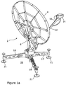
- FIGs 1-3c there is illustrated a first embodiment of the invention.
- an antenna assembly 2 which is shown in an in-use position in Figures 1a-c .
- the assembly includes an antenna or reflector 4 which is mounted via a support bracket 6 located at and in engagement with the rear of the antenna 4 and a support hub 10.
- a boom arm 12 located on the support hub 10 at one end 11 and which typically is provided to receive a transceiver and/or other data signal processing apparatus 14 at the free end 16 thereof.
- the support hub 10 is also located with support legs 17,18,19 which, in this embodiment form a tripod.
- Each of the support legs are provided with adjustable height feet 21 to allow the same to be positioned on a support surface, such as the ground 20, and therefore the apparatus can be deployed and supported remotely from any structure, such as may be required for use in temporary locations, for example, in outside broadcast and/or military requirements.
- the adjustment is made using two forms of adjustment actuation means for each of the azimuth and elevation positions.
- the first adjustment means allow relatively coarse adjustment of the position of the antenna and this is provided via a manually rotatable handle and pivot shaft 28 on the bracket 6 for elevation adjustment and a manually rotatable knob with a threaded shaft 30 mounted on the support hub 10 for azimuth adjustment.
- the installer will adjust the position of the handle 28 and knob 30 respectively until, typically, a visual indicator indicates that the required position orientation of the antenna is at a desired location and therefore the antenna is now at or close to the desired position with regard to the geographical location of the assembly at that time and the one or more satellites from and/or to which the data signals are required to pass.
- the coarse adjustment means 28, 30 can be locked in that position.
- Second adjustment means are also provided for each of the elevation and azimuth positions and these are provided in the form of a rotatable sleeve on a threaded shaft 32 to allow the fine elevation adjustment and a knob with a threaded shaft 34 to allow fine azimuth adjustment.
- the position is locked in position for optimum use at that location.
- the locking means are provided integrally with the fine elevation adjustment assembly 32 and a separate locking means 36 is provided on the support hub 10 to lock the fine azimuth position of the antenna 4.
- bracket 6, support hub 10, boom arm 12 and support legs can all be manufactured from relatively light weight composite, anodised metal materials.
- the relative positions of the same parts can be changed between storage and in-use positions so, when in the storage position a significantly smaller, and hence more portable assembly can be achieved.
- the assembly can be formed as three parts when in the storage position comprising, the antenna 4, support hub, bracket and support legs, and the boom arm. In this storage position the assembly may be transportable in two carrying holdalls.
- the assembly may include one or more solar panels, charger controller inverter and rechargeable battery in order to allow the operation of the assembly data processing means and other optional powered components remotely from mains or other power sources.
- the antenna assembly is provided to operate in the Ka band of data signals and In order to allow the assembly 2 to be movable from the in-use position shown in Figures 1a-c to the storage position, the assembly components are required to be selectively movable.
- Figure 2b illustrates the bracket 6, support hub and support legs 17,18,19 of the assembly in a storage position.
- the bracket 6 is pivotally connected to the support hub 10 via a pivot connection 38 located on a first side 44 of the support hub 10, which allows pivotal movement of the bracket 6 as indicated by arrow 42 about the axis 40 so as to allow the bracket 6 to be selectively moved between the storage position shown in Figure 2b to the in-use position shown in Figure 2a .
- Each of the support legs 17,18,19 are connected to the edge or, as shown in this embodiment, the second opposing side 46 of the support hub 10 via respective pivot connections 48, 50, 52 which allow pivotal movement of the support legs about respective axes 54, 56, 58 so as to move the support legs from the storage position shown in Figure 2b and the spaced apart in-use position shown in Figure 2a .
- the axes 54,56,58 are perpendicular to the axis 40.
- the support legs 17,18,19 are spaced apart from the bracket 6 by the thickness of the support hub 10 but lie along substantially the same axis 60 to thereby minimise the volume of the same for storage purposes.
- the boom arm 12 end 11 can be selectively engaged with the support hub 10 via mechanical connection means 62.
- the antenna 4, in this embodiment is formed of first and second segments 64, 66 which, when in the storage position can overlie each other and when in the in-use position are joined together along interface 68 and are held together by "quick release" locking levers 70, spaced long the interface at the rear face 72 on the antenna so as to ensure a smooth front face 23 is formed as shown in Figure 1c .
- the bracket arms 74, 76 are provided with "quick release” locking levers 78, which are pivotally movable towards the rear surface 72 of the antenna 4 when in position so as to engage with ribs 80 on the rear face and thereby retain the antenna 4 in the in-use position and allow the adjustment of the azimuth and elevation of the same with respect to the support hub 10.
- the support hub 10 is shown in more detail in Figures 3a-c and it will be seen that it comprises an upper part 82 with the first side 44 and a lower part 84 with the second side 46.
- the upper part has the pivot connection 38 with which the bracket 6 engages top move about axis 40 and the lower part 84 has engagement means 86 to which the support legs 17,18,19 mounting 88 is engaged.
- the elevation scale 90 to which the user can refer when adjusting the elevation orientation of the antenna 4 and location means 92 for one end of the threaded shaft 94 via which the elevation adjustment can be performed with the coarse adjustment handle 28 at the opposing end of the threaded shaft 94 and the fine adjustment sleeve 32 mounted on the threaded shaft 94.
- a spirit level indicator 96 is also provided to assist in the positioning and adjustment of the support legs and hence support hub 10.
- the upper part 82 is rotatably adjustable with respect to the lower part 84 about the axis 98 using bearing assembly 100 in order to allow the adjustment of the azimuth orientation of the antenna 4, bracket 6 and upper part 82 with respect to the remainder of the support hub and support legs the amount of azimuth adjustment is selected by operation of the coarse and fine adjustment knobs 30, 34 and when the desired azimuth adjustment is achieved the relative movement of the upper part 82 with respect to the lower part 84 is locked by the tightening of the locking knob 36.
- the antenna assembly 2 includes an antenna or reflector 4 which is mounted via a support bracket 6 which has a first part located at the rear of the antenna 4 and a support hub 10. Also provided is a boom arm 12.
- the support 10 is shown mounted on a tripod formed by support legs 17,18,19 which is provided with feet 21 to allow the same to be positioned on a support surface such as the ground 20.
- the bracket 6 is located on a pole 122 which, in turn, is provided with a mounting plate 124 which allows the same to be mounted and located on a support surface 126 in the form of, typically, a wall of a building.
- the first adjustment actuation means as illustrated in Figures 6 and 7 allow relatively coarse adjustment of the position of the antenna and this is provided via manually rotatable knob with a threaded shaft 28 for elevation adjustment and manually rotatable knob with a threaded shaft 30 for azimuth adjustment and the installer will manually rotate the knobs until, typically, a visual indicator on one of the bracket part 8 or hub 10, is visually matched with a predetermined one of a number of graduation markings on the other of the bracket part 8 or hub 10 so that the personnel installing the apparatus can simply adjust using these first adjustment actuation means to bring the antenna to or close to the required position.
- the second adjustment actuation means also includes a manually operable knob with a threaded shaft 32 to allow the fine elevation adjustment and manually operable knob with a threaded shaft 34 to allow fine azimuth adjustment.
- Figure 7 shows one example and includes the use of a servo motor 35 for the fine elevation adjustment and servo motor 37 for the fine azimuth adjustment.
- this adjustment is controlled automatically by control means which are connected to the antenna assembly and which monitor the strength and quality of data signals received by the antenna at a particular position as the automatic adjustment of the orientation of the antenna is performed by the control means controlling the operation of the servo motors 36 and 38.
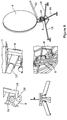
- FIG 8 illustrates the manner in which the antenna assembly 2 of Figure 4 and 5 can be assembled in accordance with one embodiment of the invention and subsequent to the installation steps 1 to 4 shown in Figure 8 the adjustment of the azimuth and elevation orientation of the antenna 4 will be performed.
Landscapes
- Variable-Direction Aerials And Aerial Arrays (AREA)
Description
- The invention to which this application relates is a mounting system for use particularly, although not necessarily exclusively, in the mounting of an antenna assembly on a support surface, in one embodiment in the form of a mounting assembly, such as a tripod, mounted on the ground.
- The provision of an antenna assembly to receive broadcast data signals, such as those which are broadcast and transmitted by a satellite transmission system. Typically, at any location where it is desired to receive the satellite transmitted data signals, such as a location where a subscription has been taken out by a person to receive the data signals for a television and/or radio service, or, in other uses, such as military usage, an antenna assembly is required to be mounted on a support and the antenna is required to be directed towards the position which is optimum for the best reception of data signals from one or more satellites. This allows any errors in the reception of the data signals to be minimised, and which errors can cause disruption to the service generated to the end user by processing the data signals downstream of the antenna.
- Conventionally, the antenna assembly comprises an antenna that is mounted on a bracket at the rear surface of the antenna which, in turn, is located on a support, and an arm is provided to the front of the antenna on which a receiver or transceiver and/or other data processing means are mounted. The bracket is, in turn, located on a pole or tripod that provides the support for the position of the antenna and maintains that antenna in that position during use.
- Conventionally, at least part of the assembly is required to be assembled on site so that, in addition to the mechanical connection of the components, it is also then necessary to adjust the relative positions of the components of the apparatus and particularly the location of the antenna in relation to the bracket and/or support to adjust the same with respect to the satellites from which the data signals are received at the location of use.
- In order to ensure that the transmitted data signals are received by the antenna with sufficient accuracy so that any error in the data signals is sufficiently low so as to not disrupt the subsequent processing of the signals, it is important that the antenna assembly is correctly and accurately located at the time of installation. This requirement for accuracy may vary between different types of antenna and/or their uses but is always a requirement. For example, with certain types of antenna, such as a very small aperture terminal (VSAT) antenna, which is typically a two way transmission system and which can be used in transportable, "on-the-move" systems such as military, emergency situations and temporary site requirements and/ or mobile maritime communications, there is a need for relatively skilled personnel to be used to install and deploy the apparatus in order for the same to operate satisfactorily. The requirement of skilled personnel to be used, on site, means that the cost of installation of the apparatus is relatively high. However, until now, the cost has been deemed to be unavoidable, due to the requirement for the skilled deployment and setting of the apparatus in order for the same to operate effectively.
-
US4994816 disclosed an adjustable antenna assembly in which there is provided a relatively complex lever arrangement between the underside of the antenna and the support hub and a boom arm which is a pivotal member arrangement which is provided as part of the bracket.US2012068899 andWO2009088111 describe assemblies which do not utilise a boom arm or the movement of a boom arm between storage and in-use conditions.EP1798810 disclose an assembly in which the support legs depend from an edge of a hub, rather than the side of the hub which opposes that to which the antenna bracket is attached andUS7142168 discloses apparatus for adjustment of an antenna rather than any rapid deployment antenna assembly.US2007/241155 discloses another antenna assembly which is moveable between storage and in use conditions. - An aim of the present invention is therefore to allow the antenna apparatus to be provided to be used at a location in a manner which can be installed and deployed by personnel who need not have the same level of skill as is conventionally required and, as a result, thereby reduce the cost of installation whilst, at the same time, ensuring that the accuracy of installation of the assembly is maintained. A further aim is to allow the apparatus, if required, to be installed and disassembled relatively rapidly so as to suit particular usage requirements, such as military usage requirements.
- In a first aspect of the invention there is provided an antenna assembly, as disclosed in claim 1.
- In one embodiment the support legs are equally spaced around the hub when in the in use positions and lie substantially adjacent each other when in the storage position. In one embodiment the bracket lies substantially in line with the support legs when in the storage position but spaced therefrom on the opposing side of the hub.
- In one embodiment the control means include a modem which detects the strength of the received data signal, as adjustment of the position of the antenna is performed and, when the received data signal is detected as being of a predetermined condition, the adjustment is stopped and the antenna position is set. In one embodiment the predetermined condition is the detection of the data signal with a Bit Error Rate which is deemed to be at, or better than, a predetermined value for acceptable further processing to allow the required service to be generated from the received data signals.
- In one embodiment, the first adjustment means includes manually operable adjustment actuators and the second adjustment means includes powered actuators which in one embodiment are servo motors.
- In a further aspect of the invention, there is provided a method for moving an antenna to an in-use position from a storage position, the said method including the steps of moving support legs pivotally with respect to respective pivot connections on a second side of a hub to a spaced, in-use, position, moving a bracket pivotally with respect to a pivot connection on a first side of the hub to an in-use position, locating first and second segments of an antenna joined together along an interface to the bracket, mounting a boom arm in position on the said hub with a free end of the boom arm with data processing means positioned in front of the reflecting surface of the antenna and first and second adjustment means, to provide coarse and fine tuning respectively of azimuth and elevation positions of the antenna are selectively operated to allow adjustment of the position of the antenna by selectively operating, for each of elevation and azimuth, the first adjustment means, locking the same and then selectively operating the second adjustment means, which differ to the first adjustment means, in order to provide the antenna at the desired position for receipt of the data signals of a predetermined condition characterised in that the adjustment of the second adjustment means is controlled by an automatic directing system utilising a control means connected to the antenna assembly to determine the extent of the adjustment required using the second adjustment means.
- In one embodiment the control means are provided which include a modem which detects the strength of the received data signal as operating, for each of elevation and azimuth, the first adjustment means, locking the same and then selectively operating the second adjustment means which differ to the fist adjustment means in order to provide the antenna at the desired position for receipt of the data signals of a predetermined condition.
- In one embodiment the control means are provided which include a modem which detects the strength of the received data signal as adjustment of the position of the antenna is performed and, when the received data signals are detected as being in the predetermined condition, adjustment is stopped and the antenna position is locked with respect to the support hub and support legs.
- In one embodiment the predetermined condition is met when the received data signal has a bit error rate which is at, or better than, a predetermined value.
- Specific embodiments of the invention are now described with reference to the accompanying drawings; wherein
-
Figures 1-3c illustrate a first embodiment of the invention; -
Figures 4a and b illustrate a second embodiment of an antenna assembly in accordance with the invention. -
Figure 5 illustrates a third embodiment of an antenna assembly in accordance with the invention. -
Figure 6 illustrates adjustment means in accordance with one embodiment of the invention. -
Figure 7 illustrates adjustment means in accordance with a second embodiment of the invention. -
Figure 8 illustrates the steps which can be performed in the method of assembly of the apparatus in accordance with the invention. - In
Figures 1-3c there is illustrated a first embodiment of the invention. There is provided anantenna assembly 2 which is shown in an in-use position inFigures 1a-c . The assembly includes an antenna orreflector 4 which is mounted via asupport bracket 6 located at and in engagement with the rear of theantenna 4 and asupport hub 10. Also provided is aboom arm 12 located on thesupport hub 10 at oneend 11 and which typically is provided to receive a transceiver and/or other datasignal processing apparatus 14 at thefree end 16 thereof. Thesupport hub 10 is also located withsupport legs adjustable height feet 21 to allow the same to be positioned on a support surface, such as theground 20, and therefore the apparatus can be deployed and supported remotely from any structure, such as may be required for use in temporary locations, for example, in outside broadcast and/or military requirements. - When the antenna assembly is in the in-use position as shown in
Figures 1a-c there is a need to be able to adjust and set the position of theantenna 4 so that the same is provided in the optimum position, both with respect to elevation and azimuth orientations, to receive data signals which are transmitted from one or more satellites and thereby allow the data signals which are received on thefront surface 23 of theantenna 4 and reflected to the data processing means 14, to be received with a minimum of error. It is known that if the quality of the received data signals is poor due to the incorrect orientation of theantenna 4 and that as a result the data signals include a bit error rate above a certain level, then the quality of the received data signals will be such that the same cannot be accurately processed, in which case the desired service cannot be satisfactorily provided to the user of the antenna assembly. - In accordance with the invention the adjustment is made using two forms of adjustment actuation means for each of the azimuth and elevation positions.
- The first adjustment means, as illustrated in
Figures 1a-c to Figure 3c , allow relatively coarse adjustment of the position of the antenna and this is provided via a manually rotatable handle andpivot shaft 28 on thebracket 6 for elevation adjustment and a manually rotatable knob with a threadedshaft 30 mounted on thesupport hub 10 for azimuth adjustment. In use the installer will adjust the position of thehandle 28 andknob 30 respectively until, typically, a visual indicator indicates that the required position orientation of the antenna is at a desired location and therefore the antenna is now at or close to the desired position with regard to the geographical location of the assembly at that time and the one or more satellites from and/or to which the data signals are required to pass. At this point the coarse adjustment means 28, 30 can be locked in that position. - Second adjustment means are also provided for each of the elevation and azimuth positions and these are provided in the form of a rotatable sleeve on a threaded
shaft 32 to allow the fine elevation adjustment and a knob with a threadedshaft 34 to allow fine azimuth adjustment. - Once the fine adjustment has been performed to more accurately select the orientation of the antenna with respect to azimuth and elevation, then the position is locked in position for optimum use at that location. In this embodiment the locking means are provided integrally with the fine
elevation adjustment assembly 32 and a separate locking means 36 is provided on thesupport hub 10 to lock the fine azimuth position of theantenna 4. - In order to allow the antenna assembly to be deployable and disassembled relatively quickly the antenna or
reflector 4,bracket 6,support hub 10,boom arm 12 and support legs can all be manufactured from relatively light weight composite, anodised metal materials. Furthermore as will now be described, the relative positions of the same parts can be changed between storage and in-use positions so, when in the storage position a significantly smaller, and hence more portable assembly can be achieved. In one embodiment the assembly can be formed as three parts when in the storage position comprising, theantenna 4, support hub, bracket and support legs, and the boom arm. In this storage position the assembly may be transportable in two carrying holdalls. Optionally the assembly may include one or more solar panels, charger controller inverter and rechargeable battery in order to allow the operation of the assembly data processing means and other optional powered components remotely from mains or other power sources. - In one embodiment the antenna assembly is provided to operate in the Ka band of data signals and
In order to allow theassembly 2 to be movable from the in-use position shown inFigures 1a-c to the storage position, the assembly components are required to be selectively movable.Figure 2b illustrates thebracket 6, support hub andsupport legs bracket 6 is pivotally connected to thesupport hub 10 via apivot connection 38 located on afirst side 44 of thesupport hub 10, which allows pivotal movement of thebracket 6 as indicated byarrow 42 about theaxis 40 so as to allow thebracket 6 to be selectively moved between the storage position shown inFigure 2b to the in-use position shown inFigure 2a . Each of thesupport legs opposing side 46 of thesupport hub 10 viarespective pivot connections respective axes Figure 2b and the spaced apart in-use position shown inFigure 2a . Typically theaxes axis 40. - When in the storage position the
support legs bracket 6 by the thickness of thesupport hub 10 but lie along substantially thesame axis 60 to thereby minimise the volume of the same for storage purposes. - The
boom arm 12end 11 can be selectively engaged with thesupport hub 10 via mechanical connection means 62. - The
antenna 4, in this embodiment is formed of first andsecond segments interface 68 and are held together by "quick release"locking levers 70, spaced long the interface at therear face 72 on the antenna so as to ensure asmooth front face 23 is formed as shown inFigure 1c . Thebracket arms locking levers 78, which are pivotally movable towards therear surface 72 of theantenna 4 when in position so as to engage withribs 80 on the rear face and thereby retain theantenna 4 in the in-use position and allow the adjustment of the azimuth and elevation of the same with respect to thesupport hub 10. - The
support hub 10 is shown in more detail inFigures 3a-c and it will be seen that it comprises anupper part 82 with thefirst side 44 and alower part 84 with thesecond side 46. - The upper part has the
pivot connection 38 with which thebracket 6 engages top move aboutaxis 40 and thelower part 84 has engagement means 86 to which thesupport legs - Also provided on the
upper part 82 is theelevation scale 90 to which the user can refer when adjusting the elevation orientation of theantenna 4 and location means 92 for one end of the threadedshaft 94 via which the elevation adjustment can be performed with the coarse adjustment handle 28 at the opposing end of the threadedshaft 94 and thefine adjustment sleeve 32 mounted on the threadedshaft 94. Aspirit level indicator 96 is also provided to assist in the positioning and adjustment of the support legs and hence supporthub 10. Theupper part 82 is rotatably adjustable with respect to thelower part 84 about theaxis 98 using bearing assembly 100 in order to allow the adjustment of the azimuth orientation of theantenna 4,bracket 6 andupper part 82 with respect to the remainder of the support hub and support legs the amount of azimuth adjustment is selected by operation of the coarse and fine adjustment knobs 30, 34 and when the desired azimuth adjustment is achieved the relative movement of theupper part 82 with respect to thelower part 84 is locked by the tightening of the lockingknob 36. - In
figures 4a to 5 , there are illustrated second and third embodiments of antenna assemblies. The components of the assembly which are common to the first, second and third embodiments are provided with the same reference numerals. Theantenna assembly 2 includes an antenna orreflector 4 which is mounted via asupport bracket 6 which has a first part located at the rear of theantenna 4 and asupport hub 10. Also provided is aboom arm 12. Infigures 4a and b , thesupport 10 is shown mounted on a tripod formed bysupport legs feet 21 to allow the same to be positioned on a support surface such as theground 20. InFigure 5 , thebracket 6 is located on apole 122 which, in turn, is provided with a mountingplate 124 which allows the same to be mounted and located on asupport surface 126 in the form of, typically, a wall of a building. - In either embodiment, there is a need, once the assembly is provided in a fixed location to be able to adjust and set the position of the
antenna 4. In the embodiments shown inFigures 1-3c and4a-5 the first adjustment actuation means as illustrated inFigures 6 and7 allow relatively coarse adjustment of the position of the antenna and this is provided via manually rotatable knob with a threadedshaft 28 for elevation adjustment and manually rotatable knob with a threadedshaft 30 for azimuth adjustment and the installer will manually rotate the knobs until, typically, a visual indicator on one of thebracket part 8 orhub 10, is visually matched with a predetermined one of a number of graduation markings on the other of thebracket part 8 orhub 10 so that the personnel installing the apparatus can simply adjust using these first adjustment actuation means to bring the antenna to or close to the required position. - In accordance with
Figure 6 the second adjustment actuation means also includes a manually operable knob with a threadedshaft 32 to allow the fine elevation adjustment and manually operable knob with a threadedshaft 34 to allow fine azimuth adjustment. - However in any of the adjustment arrangement herein described, it is possible for the first, coarse, adjustment means and/or the second, fine, adjustment means to be provided in an automatically operable form.
Figure 7 shows one example and includes the use of aservo motor 35 for the fine elevation adjustment and servo motor 37 for the fine azimuth adjustment. Thus, rather than requiring manual operation or control for the second actuation adjustment, this adjustment is controlled automatically by control means which are connected to the antenna assembly and which monitor the strength and quality of data signals received by the antenna at a particular position as the automatic adjustment of the orientation of the antenna is performed by the control means controlling the operation of theservo motors antenna 4 is stopped and theantenna 4 is then set in that position for subsequent use of the assembly. -
Figure 8 illustrates the manner in which theantenna assembly 2 ofFigure 4 and5 can be assembled in accordance with one embodiment of the invention and subsequent to the installation steps 1 to 4 shown inFigure 8 the adjustment of the azimuth and elevation orientation of theantenna 4 will be performed. - There is therefore provided in accordance with the invention a relatively rapidly deployable and antenna assembly for use for a variety of possible purposes whilst ensuring that accuracy of receipt and/or transmission of the data signals using the assembly can be achieved at the required geographical location of use. By utilising the two forms of adjustment actuation means then the level of skill required for the installation personnel is reduced and hence the cost of installation is reduced whilst, at the same time, ensuring that the accuracy of installation is maintained and also increasing the speed of installation.
Claims (9)
- An antenna assembly (2), said assembly including an antenna (4), a bracket (6), a hub (10) and a boom arm (12) including data signal receiving and/or transmitting means; said antenna comprising first and second segments (64, 66), an interface (68) and locking levers (70); said antenna (4) mounted on the bracket (6) having a first part for location with the antenna and a second part for location with the hub (10) via a pivot connection (38), wherein the hub (10) includes a plurality of legs (17,18,19) and adjustment means (28,30,32, 34) to allow the selective adjustment of the azimuth and/or elevation position of the antenna (4) with respect to the hub (10), wherein the assembly (2) is selectively movable between storage and in-use conditions by movement of said bracket (6) with respect to said hub (10) via movement about an axis of the pivot connection at, or adjacent to, a first side (44) of the hub (10), by movement of the first and second segments (64,66) of the antenna (4) from a storage, overlying position to an in-use position in which they are joined together along the interface (68) and locked using the locking levers (70), along the interface at a rear face (72) on the antenna, and by movement of the boom arm (12) from a storage position to an in-use position in which the end (11) of the boom arm (12) is selectively attachable to the hub (10) and is configured to extend to the front of a front reflecting surface of the antenna (4) and the support legs (17,18,19) are each pivotally connected to the said hub (10) and pivotally movable about the respective axes (48,50,52) between storage and in-use conditions, said axes (48, 50,52) substantially parallel and perpendicular to the axis (40) about which the bracket (6) is movable and the connections to the hub (10) are on a second side (46) of the hub (10) opposing said first side (44), said adjustment means including first and second adjustment means for respective elevation and azimuth adjustment of the antenna and, for each of the elevation and azimuth orientation of the antenna, the first adjustment means (28,30) allows coarse adjustment of the position of the antenna with respect to the hub (10) and the second adjustment means (32,34) allows fine adjustment of the position of the antenna (4) with respect to the hub (10), wherein the assembly further includes lock means to allow the coarse adjustment position of the elevation to be locked and retained and separate lock means to allow the coarse adjustment position of the azimuth to be locked and retained prior to fine adjustment of the elevation and azimuth positions respectively characterised in that the adjustment of the second adjustment means (32,34) is configured to be controlled by an automatic directing system utilising a control means connected to the antenna assembly to determine the extent of the adjustment required using the second adjustment means (32,34).
- An assembly according to claim 1 characterised in that the locking means are provided so as to retain the bracket (6) and the support legs (17,18,19) in respective in-use positions.
- An assembly according to claim 1 characterised in that the support legs (17,18,19) are substantially equally spaced around the hub (10) when in the in use position and lie substantially adjacent each other when in the storage position, wherein the bracket (6) lies substantially in line with the support legs (17,18,19) when in the storage position and spaced therefrom on the first side (44) of the hub (10).
- An assembly according to any of the preceding claims characterised in that the interface (68) passes substantially along a diameter of the antenna (4) when in the use position.
- An assembly according to claim 1 characterised in that actuation of the coarse (28,30) and/or fine adjustment means (32,34) for elevation and/or azimuth are actuated by powered drive means (36,38).
- An assembly according to claim 1 characterised in that the control means include a modem configured to detect the strength of the received data signals as adjustment of the position of the antenna (4) is performed and, when the received data signals are detected as being of a predetermined condition, the adjustment is configured to be stopped and the antenna position is configured to be set with respect to elevation and/or azimuth.
- An assembly according to claim 6 characterised in that the predetermined condition is the detection of a data signal with a bit error rate which is deemed to be at, or better than, a predetermined value deemed to allow acceptable further processing of the data to allow the required service to be generated from the received data signals.
- A method for moving an antenna (4) to an in-use position from a storage position, the said method including the steps of moving support legs (17,18,19) pivotally with respect to respective pivot connections on a second side (46) of a hub (10) to a spaced, in-use, position, moving a bracket (6) pivotally with respect to a pivot connection on a first side (44) of the hub to an in-use position, locating first and second segments (64,66) of an antenna (4) joined together along an interface (68) to the bracket (6), mounting a boom arm (12) in position on the said hub (10) with a free end (11) of the boom arm (12) with data processing means (14) positioned in front of the reflecting surface of the antenna (4) and first and second adjustment means (28,30,32,34), to provide coarse and fine tuning respectively of azimuth and elevation positions of the antenna (4) are selectively operated to allow adjustment of the position of the antenna (4) by selectively operating, for each of elevation and azimuth, the first adjustment means (28,30), locking the same and then selectively operating the second adjustment means (32,34), which differ to the first adjustment means, in order to provide the antenna (4) at the desired position for receipt of the data signals of a predetermined condition characterised in that the adjustment of the second adjustment means (32,34) is controlled by an automatic directing system utilising a control means connected to the antenna assembly to determine the extent of the adjustment required using the second adjustment means (32,34).
- A method according to claim 8 characterised in that control means are provided which include a modem which detects the strength of the received data signal as adjustment of the position of the antenna (4) is performed and, when the received data signals are detected as being in the predetermined condition, adjustment is stopped and the antenna position is locked with respect to the hub (10) and support legs (17,18,19) and the predetermined condition is met when the received data signal has a bit error rate which is at, or better than, a predetermined value.
Applications Claiming Priority (2)
| Application Number | Priority Date | Filing Date | Title |
|---|---|---|---|
| GBGB1703442.2A GB201703442D0 (en) | 2017-03-03 | 2017-03-03 | Improvements to installation and location of an antenna assembly |
| PCT/GB2018/050552 WO2018158594A1 (en) | 2017-03-03 | 2018-03-05 | Improvements to an antenna assembly, and the installation and location of an antenna assembly |
Publications (2)
| Publication Number | Publication Date |
|---|---|
| EP3571740A1 EP3571740A1 (en) | 2019-11-27 |
| EP3571740B1 true EP3571740B1 (en) | 2021-09-08 |
Family
ID=58543856
Family Applications (1)
| Application Number | Title | Priority Date | Filing Date |
|---|---|---|---|
| EP18714594.1A Active EP3571740B1 (en) | 2017-03-03 | 2018-03-05 | Improvements to an antenna assembly, and the installation and location of an antenna assembly |
Country Status (4)
| Country | Link |
|---|---|
| US (1) | US11233309B2 (en) |
| EP (1) | EP3571740B1 (en) |
| GB (1) | GB201703442D0 (en) |
| WO (1) | WO2018158594A1 (en) |
Families Citing this family (5)
| Publication number | Priority date | Publication date | Assignee | Title |
|---|---|---|---|---|
| CN107919519B (en) * | 2017-12-30 | 2024-08-23 | 深圳市华讯方舟光电技术有限公司 | Portable satellite search station and support frame |
| US11936095B2 (en) * | 2019-10-07 | 2024-03-19 | Commscope Technologies Llc | Telecommunications antenna mounts and associated transition covers |
| CN111799542B (en) * | 2020-06-28 | 2022-01-04 | 北京爱科迪通信技术股份有限公司 | Emergency communication satellite antenna |
| CN112582776B (en) * | 2020-12-07 | 2022-09-27 | 东莞骅国电子有限公司 | Satellite antenna base convenient for angle adjustment |
| US12176996B2 (en) * | 2021-03-08 | 2024-12-24 | Datapath, Inc. | Transportable satellite antenna terminal |
Family Cites Families (12)
| Publication number | Priority date | Publication date | Assignee | Title |
|---|---|---|---|---|
| DE68920184T2 (en) * | 1988-04-08 | 1995-06-22 | Toshiba Kawasaki Kk | Portable antenna device. |
| US5337062A (en) * | 1992-11-18 | 1994-08-09 | Winegard Company | Deployable satellite antenna for use on vehicles |
| US5646638A (en) * | 1995-05-30 | 1997-07-08 | Winegard Company | Portable digital satellite system |
| US8786506B2 (en) | 2004-04-26 | 2014-07-22 | Antennasys, Inc. | Compact portable antenna positioner system and method |
| US7142168B1 (en) * | 2004-10-01 | 2006-11-28 | Patriot Antenna Systems, Inc. | Apparatus for mounting and adjusting a satellite antenna |
| US7218289B2 (en) * | 2005-09-08 | 2007-05-15 | Norsat International Inc. | Portable high-speed data and broadcast-quality video terminal for terrestrial and satellite communications |
| US7852274B2 (en) | 2005-12-16 | 2010-12-14 | Rockwell Collins Satellite Communications Systems, Inc. | Communications trailer |
| KR101125734B1 (en) | 2008-01-10 | 2012-03-27 | 샛마크코리아(주) | Antenna system for receiving signals from satellites and method for driving the same |
| TW201037895A (en) * | 2009-04-08 | 2010-10-16 | Microelectronics Tech Inc | Angle adjustment apparatus for disk antenna and disk antenna using the same |
| US8319697B2 (en) * | 2009-10-22 | 2012-11-27 | Winegard Company | Semi-permanent portable satellite antenna system |
| DK177464B1 (en) * | 2011-12-08 | 2013-06-24 | Spacecom Holding Aps | Pedestal for tracking antenna |
| US10892542B2 (en) * | 2013-08-02 | 2021-01-12 | Aqyr Technologies, Inc. | Antenna positioning system with automated skewed positioning |
-
2017
- 2017-03-03 GB GBGB1703442.2A patent/GB201703442D0/en not_active Ceased
-
2018
- 2018-03-05 EP EP18714594.1A patent/EP3571740B1/en active Active
- 2018-03-05 WO PCT/GB2018/050552 patent/WO2018158594A1/en not_active Ceased
- 2018-03-05 US US16/489,220 patent/US11233309B2/en active Active
Also Published As
| Publication number | Publication date |
|---|---|
| US20200006839A1 (en) | 2020-01-02 |
| US11233309B2 (en) | 2022-01-25 |
| WO2018158594A1 (en) | 2018-09-07 |
| GB201703442D0 (en) | 2017-04-19 |
| EP3571740A1 (en) | 2019-11-27 |
Similar Documents
| Publication | Publication Date | Title |
|---|---|---|
| US11233309B2 (en) | Antenna assembly, and the installation and location of an antenna assembly | |
| US20230121935A1 (en) | Antenna with sensors for accurate pointing | |
| US20200119441A1 (en) | Method and apparatus for beam-steerable antenna with single-drive mechanism | |
| EP2486623B1 (en) | Antenna mast system and mounting apparatus | |
| EP2580810B1 (en) | Antenna orientation determination | |
| US7990325B2 (en) | System and method for remote antenna positioning data acquisition | |
| KR101485486B1 (en) | Apparatus and method of arranging direction of antenna in directional wireless communication system | |
| US11495882B2 (en) | Alignment means for directive antennas | |
| EP3016300A1 (en) | Indoor satellite communication | |
| US20190341671A1 (en) | Precision adjustment antenna mount apparatus and alignment method | |
| WO2009088111A1 (en) | Antenna system for receiving signals from satellites and method for driving the same | |
| EP1332532B1 (en) | Automatic antennae system | |
| US12199329B2 (en) | Removeable satellite antenna pointing tool | |
| US20240021984A1 (en) | Antenna with low-cost steerable subreflector | |
| US20100201599A1 (en) | Adjustment method for dish antenna | |
| WO2010080545A2 (en) | Subreflector tracking method, apparatus and system for reflector antenna | |
| JP2004532591A (en) | Antenna alignment method and device | |
| EP2290390A1 (en) | Satellite connection apparatus for transport means | |
| JP6873653B2 (en) | Satellite acquisition device and satellite acquisition method | |
| US20150255866A1 (en) | Swivel mounted antenna | |
| Wibisono et al. | Automatic VSAT antenna pointing system featured with non-horizontal alignment autocorrect | |
| US20240030620A1 (en) | Mounting system for use with an antenna assembly | |
| WO2024217679A1 (en) | Method and device for changing position of at least one alignment means | |
| JP2012095244A (en) | Antenna supporting apparatus | |
| de Vicente et al. | MAL-X: An X-Band terminal in Malindi for the LEOP support of ESA missions |
Legal Events
| Date | Code | Title | Description |
|---|---|---|---|
| STAA | Information on the status of an ep patent application or granted ep patent |
Free format text: STATUS: UNKNOWN |
|
| STAA | Information on the status of an ep patent application or granted ep patent |
Free format text: STATUS: THE INTERNATIONAL PUBLICATION HAS BEEN MADE |
|
| PUAI | Public reference made under article 153(3) epc to a published international application that has entered the european phase |
Free format text: ORIGINAL CODE: 0009012 |
|
| STAA | Information on the status of an ep patent application or granted ep patent |
Free format text: STATUS: REQUEST FOR EXAMINATION WAS MADE |
|
| 17P | Request for examination filed |
Effective date: 20190823 |
|
| AK | Designated contracting states |
Kind code of ref document: A1 Designated state(s): AL AT BE BG CH CY CZ DE DK EE ES FI FR GB GR HR HU IE IS IT LI LT LU LV MC MK MT NL NO PL PT RO RS SE SI SK SM TR |
|
| AX | Request for extension of the european patent |
Extension state: BA ME |
|
| DAV | Request for validation of the european patent (deleted) | ||
| DAX | Request for extension of the european patent (deleted) | ||
| STAA | Information on the status of an ep patent application or granted ep patent |
Free format text: STATUS: EXAMINATION IS IN PROGRESS |
|
| 17Q | First examination report despatched |
Effective date: 20201221 |
|
| GRAP | Despatch of communication of intention to grant a patent |
Free format text: ORIGINAL CODE: EPIDOSNIGR1 |
|
| STAA | Information on the status of an ep patent application or granted ep patent |
Free format text: STATUS: GRANT OF PATENT IS INTENDED |
|
| INTG | Intention to grant announced |
Effective date: 20210416 |
|
| RAP3 | Party data changed (applicant data changed or rights of an application transferred) |
Owner name: GLOBAL INVACOM LTD |
|
| GRAS | Grant fee paid |
Free format text: ORIGINAL CODE: EPIDOSNIGR3 |
|
| GRAA | (expected) grant |
Free format text: ORIGINAL CODE: 0009210 |
|
| STAA | Information on the status of an ep patent application or granted ep patent |
Free format text: STATUS: THE PATENT HAS BEEN GRANTED |
|
| AK | Designated contracting states |
Kind code of ref document: B1 Designated state(s): AL AT BE BG CH CY CZ DE DK EE ES FI FR GB GR HR HU IE IS IT LI LT LU LV MC MK MT NL NO PL PT RO RS SE SI SK SM TR |
|
| REG | Reference to a national code |
Ref country code: GB Ref legal event code: FG4D |
|
| REG | Reference to a national code |
Ref country code: CH Ref legal event code: EP Ref country code: AT Ref legal event code: REF Ref document number: 1429391 Country of ref document: AT Kind code of ref document: T Effective date: 20210915 |
|
| REG | Reference to a national code |
Ref country code: DE Ref legal event code: R096 Ref document number: 602018023220 Country of ref document: DE |
|
| REG | Reference to a national code |
Ref country code: IE Ref legal event code: FG4D |
|
| REG | Reference to a national code |
Ref country code: FI Ref legal event code: FGE |
|
| REG | Reference to a national code |
Ref country code: NO Ref legal event code: T2 Effective date: 20210908 |
|
| REG | Reference to a national code |
Ref country code: SE Ref legal event code: TRGR |
|
| REG | Reference to a national code |
Ref country code: LT Ref legal event code: MG9D |
|
| REG | Reference to a national code |
Ref country code: NL Ref legal event code: MP Effective date: 20210908 |
|
| PG25 | Lapsed in a contracting state [announced via postgrant information from national office to epo] |
Ref country code: BG Free format text: LAPSE BECAUSE OF FAILURE TO SUBMIT A TRANSLATION OF THE DESCRIPTION OR TO PAY THE FEE WITHIN THE PRESCRIBED TIME-LIMIT Effective date: 20211208 Ref country code: LT Free format text: LAPSE BECAUSE OF FAILURE TO SUBMIT A TRANSLATION OF THE DESCRIPTION OR TO PAY THE FEE WITHIN THE PRESCRIBED TIME-LIMIT Effective date: 20210908 Ref country code: RS Free format text: LAPSE BECAUSE OF FAILURE TO SUBMIT A TRANSLATION OF THE DESCRIPTION OR TO PAY THE FEE WITHIN THE PRESCRIBED TIME-LIMIT Effective date: 20210908 Ref country code: HR Free format text: LAPSE BECAUSE OF FAILURE TO SUBMIT A TRANSLATION OF THE DESCRIPTION OR TO PAY THE FEE WITHIN THE PRESCRIBED TIME-LIMIT Effective date: 20210908 Ref country code: ES Free format text: LAPSE BECAUSE OF FAILURE TO SUBMIT A TRANSLATION OF THE DESCRIPTION OR TO PAY THE FEE WITHIN THE PRESCRIBED TIME-LIMIT Effective date: 20210908 |
|
| REG | Reference to a national code |
Ref country code: AT Ref legal event code: MK05 Ref document number: 1429391 Country of ref document: AT Kind code of ref document: T Effective date: 20210908 |
|
| PG25 | Lapsed in a contracting state [announced via postgrant information from national office to epo] |
Ref country code: LV Free format text: LAPSE BECAUSE OF FAILURE TO SUBMIT A TRANSLATION OF THE DESCRIPTION OR TO PAY THE FEE WITHIN THE PRESCRIBED TIME-LIMIT Effective date: 20210908 Ref country code: GR Free format text: LAPSE BECAUSE OF FAILURE TO SUBMIT A TRANSLATION OF THE DESCRIPTION OR TO PAY THE FEE WITHIN THE PRESCRIBED TIME-LIMIT Effective date: 20211209 |
|
| PG25 | Lapsed in a contracting state [announced via postgrant information from national office to epo] |
Ref country code: AT Free format text: LAPSE BECAUSE OF FAILURE TO SUBMIT A TRANSLATION OF THE DESCRIPTION OR TO PAY THE FEE WITHIN THE PRESCRIBED TIME-LIMIT Effective date: 20210908 |
|
| PG25 | Lapsed in a contracting state [announced via postgrant information from national office to epo] |
Ref country code: IS Free format text: LAPSE BECAUSE OF FAILURE TO SUBMIT A TRANSLATION OF THE DESCRIPTION OR TO PAY THE FEE WITHIN THE PRESCRIBED TIME-LIMIT Effective date: 20220108 Ref country code: SM Free format text: LAPSE BECAUSE OF FAILURE TO SUBMIT A TRANSLATION OF THE DESCRIPTION OR TO PAY THE FEE WITHIN THE PRESCRIBED TIME-LIMIT Effective date: 20210908 Ref country code: SK Free format text: LAPSE BECAUSE OF FAILURE TO SUBMIT A TRANSLATION OF THE DESCRIPTION OR TO PAY THE FEE WITHIN THE PRESCRIBED TIME-LIMIT Effective date: 20210908 Ref country code: RO Free format text: LAPSE BECAUSE OF FAILURE TO SUBMIT A TRANSLATION OF THE DESCRIPTION OR TO PAY THE FEE WITHIN THE PRESCRIBED TIME-LIMIT Effective date: 20210908 Ref country code: PT Free format text: LAPSE BECAUSE OF FAILURE TO SUBMIT A TRANSLATION OF THE DESCRIPTION OR TO PAY THE FEE WITHIN THE PRESCRIBED TIME-LIMIT Effective date: 20220110 Ref country code: PL Free format text: LAPSE BECAUSE OF FAILURE TO SUBMIT A TRANSLATION OF THE DESCRIPTION OR TO PAY THE FEE WITHIN THE PRESCRIBED TIME-LIMIT Effective date: 20210908 Ref country code: NL Free format text: LAPSE BECAUSE OF FAILURE TO SUBMIT A TRANSLATION OF THE DESCRIPTION OR TO PAY THE FEE WITHIN THE PRESCRIBED TIME-LIMIT Effective date: 20210908 Ref country code: EE Free format text: LAPSE BECAUSE OF FAILURE TO SUBMIT A TRANSLATION OF THE DESCRIPTION OR TO PAY THE FEE WITHIN THE PRESCRIBED TIME-LIMIT Effective date: 20210908 Ref country code: CZ Free format text: LAPSE BECAUSE OF FAILURE TO SUBMIT A TRANSLATION OF THE DESCRIPTION OR TO PAY THE FEE WITHIN THE PRESCRIBED TIME-LIMIT Effective date: 20210908 Ref country code: AL Free format text: LAPSE BECAUSE OF FAILURE TO SUBMIT A TRANSLATION OF THE DESCRIPTION OR TO PAY THE FEE WITHIN THE PRESCRIBED TIME-LIMIT Effective date: 20210908 |
|
| REG | Reference to a national code |
Ref country code: DE Ref legal event code: R097 Ref document number: 602018023220 Country of ref document: DE |
|
| PLBE | No opposition filed within time limit |
Free format text: ORIGINAL CODE: 0009261 |
|
| STAA | Information on the status of an ep patent application or granted ep patent |
Free format text: STATUS: NO OPPOSITION FILED WITHIN TIME LIMIT |
|
| PG25 | Lapsed in a contracting state [announced via postgrant information from national office to epo] |
Ref country code: DK Free format text: LAPSE BECAUSE OF FAILURE TO SUBMIT A TRANSLATION OF THE DESCRIPTION OR TO PAY THE FEE WITHIN THE PRESCRIBED TIME-LIMIT Effective date: 20210908 |
|
| 26N | No opposition filed |
Effective date: 20220609 |
|
| PG25 | Lapsed in a contracting state [announced via postgrant information from national office to epo] |
Ref country code: SI Free format text: LAPSE BECAUSE OF FAILURE TO SUBMIT A TRANSLATION OF THE DESCRIPTION OR TO PAY THE FEE WITHIN THE PRESCRIBED TIME-LIMIT Effective date: 20210908 |
|
| PG25 | Lapsed in a contracting state [announced via postgrant information from national office to epo] |
Ref country code: MC Free format text: LAPSE BECAUSE OF FAILURE TO SUBMIT A TRANSLATION OF THE DESCRIPTION OR TO PAY THE FEE WITHIN THE PRESCRIBED TIME-LIMIT Effective date: 20210908 |
|
| REG | Reference to a national code |
Ref country code: CH Ref legal event code: PL |
|
| REG | Reference to a national code |
Ref country code: BE Ref legal event code: MM Effective date: 20220331 |
|
| PG25 | Lapsed in a contracting state [announced via postgrant information from national office to epo] |
Ref country code: LU Free format text: LAPSE BECAUSE OF NON-PAYMENT OF DUE FEES Effective date: 20220305 Ref country code: LI Free format text: LAPSE BECAUSE OF NON-PAYMENT OF DUE FEES Effective date: 20220331 Ref country code: CH Free format text: LAPSE BECAUSE OF NON-PAYMENT OF DUE FEES Effective date: 20220331 |
|
| PG25 | Lapsed in a contracting state [announced via postgrant information from national office to epo] |
Ref country code: BE Free format text: LAPSE BECAUSE OF NON-PAYMENT OF DUE FEES Effective date: 20220331 |
|
| P01 | Opt-out of the competence of the unified patent court (upc) registered |
Effective date: 20230403 |
|
| PG25 | Lapsed in a contracting state [announced via postgrant information from national office to epo] |
Ref country code: MK Free format text: LAPSE BECAUSE OF FAILURE TO SUBMIT A TRANSLATION OF THE DESCRIPTION OR TO PAY THE FEE WITHIN THE PRESCRIBED TIME-LIMIT Effective date: 20210908 Ref country code: CY Free format text: LAPSE BECAUSE OF FAILURE TO SUBMIT A TRANSLATION OF THE DESCRIPTION OR TO PAY THE FEE WITHIN THE PRESCRIBED TIME-LIMIT Effective date: 20210908 |
|
| PG25 | Lapsed in a contracting state [announced via postgrant information from national office to epo] |
Ref country code: HU Free format text: LAPSE BECAUSE OF FAILURE TO SUBMIT A TRANSLATION OF THE DESCRIPTION OR TO PAY THE FEE WITHIN THE PRESCRIBED TIME-LIMIT; INVALID AB INITIO Effective date: 20180305 |
|
| PG25 | Lapsed in a contracting state [announced via postgrant information from national office to epo] |
Ref country code: MT Free format text: LAPSE BECAUSE OF FAILURE TO SUBMIT A TRANSLATION OF THE DESCRIPTION OR TO PAY THE FEE WITHIN THE PRESCRIBED TIME-LIMIT Effective date: 20210908 |
|
| PG25 | Lapsed in a contracting state [announced via postgrant information from national office to epo] |
Ref country code: TR Free format text: LAPSE BECAUSE OF FAILURE TO SUBMIT A TRANSLATION OF THE DESCRIPTION OR TO PAY THE FEE WITHIN THE PRESCRIBED TIME-LIMIT Effective date: 20210908 |
|
| PGFP | Annual fee paid to national office [announced via postgrant information from national office to epo] |
Ref country code: SE Payment date: 20260210 Year of fee payment: 9 |
|
| PGFP | Annual fee paid to national office [announced via postgrant information from national office to epo] |
Ref country code: GB Payment date: 20260210 Year of fee payment: 9 |
|
| PGFP | Annual fee paid to national office [announced via postgrant information from national office to epo] |
Ref country code: NO Payment date: 20260312 Year of fee payment: 9 Ref country code: DE Payment date: 20260211 Year of fee payment: 9 Ref country code: IE Payment date: 20260210 Year of fee payment: 9 |
|
| PGFP | Annual fee paid to national office [announced via postgrant information from national office to epo] |
Ref country code: FI Payment date: 20260216 Year of fee payment: 9 Ref country code: IT Payment date: 20260223 Year of fee payment: 9 |
|
| PGFP | Annual fee paid to national office [announced via postgrant information from national office to epo] |
Ref country code: FR Payment date: 20260210 Year of fee payment: 9 |