EP3571489B1 - Close-coupled analyser - Google Patents
Close-coupled analyser Download PDFInfo
- Publication number
- EP3571489B1 EP3571489B1 EP18701547.4A EP18701547A EP3571489B1 EP 3571489 B1 EP3571489 B1 EP 3571489B1 EP 18701547 A EP18701547 A EP 18701547A EP 3571489 B1 EP3571489 B1 EP 3571489B1
- Authority
- EP
- European Patent Office
- Prior art keywords
- laser
- optical
- window
- wavelengths
- sample chamber
- Prior art date
- Legal status (The legal status is an assumption and is not a legal conclusion. Google has not performed a legal analysis and makes no representation as to the accuracy of the status listed.)
- Active
Links
Images



Classifications
-
- G—PHYSICS
- G01—MEASURING; TESTING
- G01N—INVESTIGATING OR ANALYSING MATERIALS BY DETERMINING THEIR CHEMICAL OR PHYSICAL PROPERTIES
- G01N21/00—Investigating or analysing materials by the use of optical means, i.e. using sub-millimetre waves, infrared, visible or ultraviolet light
- G01N21/17—Systems in which incident light is modified in accordance with the properties of the material investigated
- G01N21/25—Colour; Spectral properties, i.e. comparison of effect of material on the light at two or more different wavelengths or wavelength bands
- G01N21/31—Investigating relative effect of material at wavelengths characteristic of specific elements or molecules, e.g. atomic absorption spectrometry
- G01N21/39—Investigating relative effect of material at wavelengths characteristic of specific elements or molecules, e.g. atomic absorption spectrometry using tunable lasers
-
- G—PHYSICS
- G01—MEASURING; TESTING
- G01N—INVESTIGATING OR ANALYSING MATERIALS BY DETERMINING THEIR CHEMICAL OR PHYSICAL PROPERTIES
- G01N21/00—Investigating or analysing materials by the use of optical means, i.e. using sub-millimetre waves, infrared, visible or ultraviolet light
- G01N21/17—Systems in which incident light is modified in accordance with the properties of the material investigated
- G01N21/25—Colour; Spectral properties, i.e. comparison of effect of material on the light at two or more different wavelengths or wavelength bands
- G01N21/31—Investigating relative effect of material at wavelengths characteristic of specific elements or molecules, e.g. atomic absorption spectrometry
- G01N21/314—Investigating relative effect of material at wavelengths characteristic of specific elements or molecules, e.g. atomic absorption spectrometry with comparison of measurements at specific and non-specific wavelengths
- G01N21/3151—Investigating relative effect of material at wavelengths characteristic of specific elements or molecules, e.g. atomic absorption spectrometry with comparison of measurements at specific and non-specific wavelengths using two sources of radiation of different wavelengths
-
- G—PHYSICS
- G01—MEASURING; TESTING
- G01N—INVESTIGATING OR ANALYSING MATERIALS BY DETERMINING THEIR CHEMICAL OR PHYSICAL PROPERTIES
- G01N21/00—Investigating or analysing materials by the use of optical means, i.e. using sub-millimetre waves, infrared, visible or ultraviolet light
- G01N21/17—Systems in which incident light is modified in accordance with the properties of the material investigated
- G01N21/25—Colour; Spectral properties, i.e. comparison of effect of material on the light at two or more different wavelengths or wavelength bands
- G01N21/31—Investigating relative effect of material at wavelengths characteristic of specific elements or molecules, e.g. atomic absorption spectrometry
- G01N21/35—Investigating relative effect of material at wavelengths characteristic of specific elements or molecules, e.g. atomic absorption spectrometry using infrared light
- G01N21/3504—Investigating relative effect of material at wavelengths characteristic of specific elements or molecules, e.g. atomic absorption spectrometry using infrared light for analysing gases, e.g. multi-gas analysis
-
- G—PHYSICS
- G01—MEASURING; TESTING
- G01N—INVESTIGATING OR ANALYSING MATERIALS BY DETERMINING THEIR CHEMICAL OR PHYSICAL PROPERTIES
- G01N21/00—Investigating or analysing materials by the use of optical means, i.e. using sub-millimetre waves, infrared, visible or ultraviolet light
- G01N21/17—Systems in which incident light is modified in accordance with the properties of the material investigated
- G01N21/25—Colour; Spectral properties, i.e. comparison of effect of material on the light at two or more different wavelengths or wavelength bands
- G01N21/31—Investigating relative effect of material at wavelengths characteristic of specific elements or molecules, e.g. atomic absorption spectrometry
- G01N21/39—Investigating relative effect of material at wavelengths characteristic of specific elements or molecules, e.g. atomic absorption spectrometry using tunable lasers
- G01N2021/396—Type of laser source
- G01N2021/399—Diode laser
-
- G—PHYSICS
- G01—MEASURING; TESTING
- G01N—INVESTIGATING OR ANALYSING MATERIALS BY DETERMINING THEIR CHEMICAL OR PHYSICAL PROPERTIES
- G01N21/00—Investigating or analysing materials by the use of optical means, i.e. using sub-millimetre waves, infrared, visible or ultraviolet light
- G01N21/01—Arrangements or apparatus for facilitating the optical investigation
- G01N21/03—Cuvette constructions
- G01N21/031—Multipass arrangements
-
- G—PHYSICS
- G01—MEASURING; TESTING
- G01N—INVESTIGATING OR ANALYSING MATERIALS BY DETERMINING THEIR CHEMICAL OR PHYSICAL PROPERTIES
- G01N2201/00—Features of devices classified in G01N21/00
- G01N2201/06—Illumination; Optics
- G01N2201/061—Sources
- G01N2201/06113—Coherent sources; lasers
- G01N2201/0612—Laser diodes
-
- G—PHYSICS
- G01—MEASURING; TESTING
- G01N—INVESTIGATING OR ANALYSING MATERIALS BY DETERMINING THEIR CHEMICAL OR PHYSICAL PROPERTIES
- G01N2201/00—Features of devices classified in G01N21/00
- G01N2201/06—Illumination; Optics
- G01N2201/063—Illuminating optical parts
- G01N2201/0633—Directed, collimated illumination
-
- G—PHYSICS
- G01—MEASURING; TESTING
- G01N—INVESTIGATING OR ANALYSING MATERIALS BY DETERMINING THEIR CHEMICAL OR PHYSICAL PROPERTIES
- G01N2201/00—Features of devices classified in G01N21/00
- G01N2201/06—Illumination; Optics
- G01N2201/066—Modifiable path; multiple paths in one sample
- G01N2201/0668—Multiple paths; optimisable path length
Definitions
- the present invention relates to a laser detection system for detecting the presence or amounts of specified gases, for example a system for gas analysis based on laser absorption spectroscopy.
- Measuring purity of a gas is essential for a manufacturer of gas.
- a purity measurement allows gas to be sold at a specified quality. Any gas produced that does not meet the quality requirements set by a manufacturer is likely to be wasted, for example flared. Therefore, to avoid waste, it is important that the purity measurement is reliable
- Continuous emission monitoring instruments are increasingly needed to monitor industrial pollution output in various industrial sites, for example at power plants, process industry factories and commercial shipping facilities. The need arises from efficiency improvements, health and safety considerations and legislative requirements. Legislative requirements often cover measurements on a range of multiple emitted compounds, for example: sulphur dioxide, nitrogen oxides, carbon monoxide, carbon dioxide, methane, water and oxygen.
- Known gas analysis systems may be at risk to potential cross-interference effects arising from atmospheric air. This is a problem when typical impurities being measured include compounds present in air, particularly when attempting to measure a quantity of these impurities below levels found in the atmosphere. Impurities that can be found in the atmosphere include, but are not limited to methane, water and carbon dioxide. Purge systems using dry nitrogen may be used to alter the atmosphere in the volume surrounding the gas detector. Alternatively, chemical scrubbing can also be used to address this problem, for example a carbon dioxide and/or oxygen scrubber. Both can be difficult to engineer and rely on the presence of utilities such as dry nitrogen or instrument air.
- GB 2 391 310 A describes a gas sensor using the principle of infra-red (IR) absorption.
- US 2008/198027 A1 describes a quarternary tunable Mid-IR laser to measure both particles and gas at the same time. The measurement is done within an area of which the gas of interest will absorb the Mid-IR radiation. By widely tuning the emission wavelength of the laser, several wavelengths can be measured in order to accurately find both gas composition and particle density with one laser based sensor.
- EP 2 927 668 A1 describes a device for combining two or more separate components of an optical analysis system, to use common entrance and exit apertures for optical measurements across a measurement space such as a stack, combustion chamber, duct or pipeline, in such way that the optical paths from the respective light sources to detectors are substantially the same, enabling multiple optical measurements over a single optical path or closely aligned optical paths with equivalent ambient conditions such as temperature and pressure distribution and background substance concentrations.
- the device and a set of interconnectable devices forming a modular system are useful, for example, in absorption spectroscopy, such as for measuring the amount fraction of the chemical constituents of a fluid in a measurement volume.
- US 5,500,768 A describes a gas spectroscopy device comprising a laser diode/lens assembly, wherein a planar reference surface of a base portion of the laser diode/lens assembly is pressure fitted into a cylindrical mounting opening first end of a laser mounting member until the laser diode housing compresses a rubber o-ring and a ledge reference surface of base portion is pressed against and therefore spatially referenced to an inside ledge surface of the laser mounting opening.
- a second end of the laser mounting member is disposed in a first end of a joining tube member, and a first end of a sample cell tube member is disposed in a second end of the joining tube member so that an axial hole in the sample cell tube member is aligned with an axial hole in the laser mounting member.
- US 2014/291526 A1 describes a gas analyser including a first housing with a laser and a detector, wherein by means of a flange the first housing is captively attached to a counterflange of a gas probe.
- the present invention is defined in claim 1 and provides a laser detection system.
- the sample chamber may comprise an optical cell.
- the optical cell may be configured to perform the receiving and containing of the sample gas.
- the material(s) may comprise any suitable compound(s), for example any suitable gaseous compounds.
- the close-coupling arrangement may be such that in operation the laser beams are substantially not absorbed by gas present between the laser housing and the at least one window.
- the intensity of the laser beams may be reduced by less than 1% optionally less than 0.1% by passage between the laser housing and the at least one window.
- the separation between the laser housing and the at least one window may be less than 1%, optionally less than 0.1% of a path length of each laser beam within the housing.
- the sample chamber may be sealed and/or the system may comprise means for controlling the pressure and/or gaseous content of the sample chamber.
- Each laser housing may be sealed and/or may be under vacuum or may contain a selected gas and/or be at a selected pressure.
- the detector apparatus may comprise a housing and at least one of: the detector apparatus housing may be sealed and/or may be under vacuum or may contain a selected gas and/or is at a selected pressure.
- the at least one aperture of the at least one laser housing may comprise at least one window through which the laser beams pass in operation, and the at least one window of the at least one laser housing is in direct contact with the at least one window of the first optical interface.
- the at least one window of the second optical interface may be in direct contact with the detector apparatus.
- the at least one laser housing may comprise an exit aperture through which the respective laser beam exits the laser, and in the close coupling arrangement, each of the laser exit apertures may be in direct contact with, or separated by less than 1 mm from, the window or a respective one of the windows of the first optical interface.
- the detector apparatus may comprise a housing having an entry aperture for passage of the light output from the sample chamber and in the close coupling arrangement, the detector entry aperture may be in direct contact with, or separated by less than 1 mm from, the window or a respective one of the windows of the second optical interface.
- the system may further comprise at least one coupling means configured to hold the at least one laser housing in the close coupling arrangement .
- the at least one window of the first optical interface may comprise one or more flat or wedged optical windows, wherein each window may be associated with a respective at least one of the lasers.
- the system may comprise at least one collimating lens associated with the window or at least one of the windows of the first optical interface.
- the system may further comprise at least one directing device inside the sample chamber configured to direct laser beams passing through the one or more windows to an optical cell in the sample chamber, wherein the at least one directing device may be configured to direct the laser beams along a common optical path to the optical cell.
- the at least one directing device inside the sample chamber may comprise a plurality of optical components arranged such that, for each laser beam a respective at least one of the optical components is arranged to direct said laser beam along the common optical path.
- the plurality of optical components may be arranged substantially in a straight line. At least one of the optical components may comprise a flat or non-wedged optical component.
- Each of the lasers and associated windows may be arranged such that in operation each of the lasers transmits its laser beam to its corresponding at least one of the optical components in a direction substantially orthogonal to said straight line.
- the plurality of optical components may comprise at least one partially reflective mirror and/or at least one dichroic mirror.
- the optical components may be arranged in series and may be configured such that in operation each optical component directs a laser beam from its associated laser to join said common optical path, and directs or allows passage of laser beam(s) from preceding optical components in the series along said common optical path.
- Each of the optical components may be at least partially reflective and at least partially transmissive.
- the at least one directing device may comprise steering optics between the last of said plurality of optical components and the optical cell and configured to direct the laser beams into the optical cell.
- the detector apparatus may one or more detectors, each detector being configured to detect radiation of a respective wavelength or range of wavelengths.
- the at least one window of the second optical interface may comprise one or more flat or non-wedged optical windows, wherein each window is associated with a respective one of the detectors.
- the system may comprise further steering optics inside the sample chamber between the optical cell and the second optical interface and configured to direct light from the optical cell to the second optical interface.
- Each of the windows and/or plurality of optical components may have a thickness in a range 0.1 mm to 1mm.
- the controller may be configured to control operation of the lasers such that each laser beams is pulsed at a rate in a range 1 kHz to 200 kHz, optionally in a range 10 kHz to 100 kHz, and/or the controller may be configured to control the lasers such that each laser beams is pulsed with pulse lengths in a range 100 ns to 20,000 ns.
- the sample gas may comprise at least one of ethylene, H 2 , N 2 , or natural gas.
- the plurality of materials may comprise at least one of: CO 2 , CO, H 2 O, CH 4 and NH 3 .
- Each of the plurality of lasers may be configured to produce infrared laser radiation.
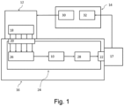
- FIG. 1 is a schematic representation of a laser spectroscopy system for analysing gas collected in an optical cell 10.
- the system comprises a laser apparatus 12, a controller 14, a sample apparatus 16 and a detector apparatus 17.
- the controller 14 is electronically, electrically or otherwise connected to the laser apparatus 12 and the sample apparatus 16.
- the laser apparatus 12 is optically coupled to the sample apparatus 16 and the sample apparatus 16 is optically coupled to the detector apparatus 17.
- the laser apparatus 12 comprises one or more lasers 18.
- Each of the one or more lasers 18 may be comprised in a laser module having a respective housing and aperture that may include a window through which the laser beam(s) pass in operation.
- the sample apparatus 16 includes the optical cell 10.
- the sample apparatus 16 also includes a first optical interface 20, a second optical interface 22 and a sample chamber 24.
- the sample apparatus 16 also includes at least one directing device in the form of a plurality of optical components 26 arranged to direct laser beams from the one or more lasers 18 along a common optical path into the optical cell 10, as described in more detail below in relation to Figure 3 .
- the optical cell 10 is contained inside the sample chamber 24.
- the at least one directing device and the steering components 28 are also contained inside the sample chamber 24.
- the sample chamber 24 is optically coupled to the laser apparatus 12 by the first optical interface 20.
- the sample chamber 24 is optically coupled to the detector apparatus 17 by the second optical interface 22.
- the detector apparatus 17 comprises a plurality of detectors.
- the detectors are configured to detect light from the optical cell 10.
- the light may be infra-red or visible light or light of any other suitable wavelength or from any suitable part of the electromagnetic spectrum.
- the controller 14 comprises a control module 30 and a signal processor 32.
- the control module 30 is configured to control operation of the lasers 18 and the signal processor 32 is configured to process signals obtained from the detector apparatus 17.
- the controller 14 may be, for example, in the form of a suitably programmed PC or other computer, or may comprise dedicated circuitry or other hardware, for example one or more ASICs or FPGAs or any suitable mixture of hardware and software.
- the control module 30 and processing module may be provided as separate, distinct components in some embodiments, for example separate processing resources, rather than being provided within the same controller component as shown in Figure 1 .
- the optical cell 10 has an optical entrance aperture and an optical exit aperture.
- the optical cell 10 may, for example, be a Herriott cell or any other suitable type of optical cell.
- the optical cell 10 is set inside the sample chamber 24.
- the sample chamber 24 of Figure 1 defines a first enclosed volume into which a sample of gas can be introduced and collected.
- the optical cell 10 defines a second open volume smaller than the first enclosed volume and inside the first enclosed volume of the sample chamber 24. A sample of gas introduced and collected into the first enclosed volume is therefore introduced and collected into the second open volume defined by the optical cell 10.
- the gas can comprise one or more different compounds or other materials of interest.
- An indication of the presence of these compounds in the gas collected in the optical cell 10 can be determined by passing light from the lasers 18 through the optical cell 10. If the light is in a wavelength range that corresponds to the absorption spectrum or absorption lines of the compound of interest, then any absorption of light as it passes through the cell may be due to the presence of the compound of interest in the sample.
- the level of absorption, once determined, can be used to determine a physical property of the compound of interest in the sample, for example, concentration. As different compounds have absorption spectra at different wavelength, different wavelengths of light are provided to the optical cell 10.
- the one or more lasers 18 are directly coupled to the first optical interface 20 in a close-coupling arrangement.
- the detectors of the detector apparatus 17 are directly coupled to the second optical interface 22 in a close-coupling arrangement.
- the close-coupling arrangement may be such that the optical components are separated by a distance less than 1mm.
- the optical components in the close-coupled arrangement may be in contact, touching and/or butt-coupled.
- Direct coupling of the lasers and detectors to the optical interface of the sample chamber offers the advantage that the optical path between laser and detector, traversed by a laser beam, is contained substantially, within the sample chamber.
- the path length of laser light outside the optical cell 10 is less than 2mm preferably less than 1 mm. This is to be compared to typical prior art arrangements, where the path length outside the cell can be 50 to 70 cm. This has the effect that the laser beam is not exposed to atmospheric air outside the sample chamber and the compounds contained therein. In other words, the laser beam may be exposed to only the sample gas contained in the sample chamber.
- Figure 2 is a more detailed schematic view of the sample apparatus 16.
- Figure 2 shows a representative laser 34 of the laser apparatus 12 having a housing and a representative detector 36 of the detector apparatus 17 having a housing.
- the housing of the laser 34 includes an aperture that has a window through which a laser beam from the laser passes in operation.
- Figure 2 also shows the sample chamber 24.
- the sample chamber 24 is coupled to the laser apparatus 16 via the first optical interface 20 and to the detector apparatus 17 via the second optical interface 22.
- the first optical interface 20 is represented by a first window 38 and a lens 42 in Figure 2 .
- the second optical interface 22 is represented by a second window 40.
- the first window 38 and the second window 40 are flat or non-wedge shaped windows.
- the lens 42 is a collimating lens and is positioned inside the sample chamber 24 at the first window 38.
- first window 38 and second window 40 are both positioned on the same face of the sample chamber 24.
- Figure 2 is a schematic diagram only and the positions of the first and second window may be different.
- the layout of the sample apparatus 16 may be different.
- the optical components 26 comprise a set of partially reflective mirrors 54 and a dichroic mirror 56.
- the dichroic mirror is included as this embodiment may be used in relation to the measurement of O 2 . In other embodiments no dichroic mirror is used, as discussed further below.
- the partially reflective mirrors 54 comprise a first mirror 60, a second mirror 62, a third mirror 64, a fourth mirror 66 and a fifth mirror 67.
- the lasers 18 comprise a first laser 68, a second laser 70, a third laser 72, a fourth laser 74, a fifth laser 76 and a sixth laser 78.
- a mirror other than a dichroic mirror or partially reflective mirror may be used at the position of the dichroic mirror 56, e.g. at the last mirror position before point 104. Such a mirror may be used at the last position to introduce more power into the cell. This can be possible as or if the last position does not have any additional lasers behind it such that no lasers need to pass through the last position.
- any suitable number and combination of partially reflective mirrors and dichroic mirrors may be used.
- the mirrors are arranged such that laser beams from the lasers 68, 70, 72, 74, 76 and 78 pass along a common optical path to the cell 10 via point 104 after passing through their corresponding window 80, 82, 84, 86, 88 and 90, being focussed by their corresponding lens 92, 94, 96, 98, 100 and 102 and being reflected by their corresponding optical components 60, 62, 64, 66, 67 and 58.
- the common optical path may, for example, have one end at the first mirror 60 and the other end at the entrance aperture to the optical cell 10 and may extend through point 104 and when directed to pass along the common optical path, the optical paths of each respective laser joins the common optical path.
- the optical paths of each laser may substantially overlap.
- the laser modules can be swapped for other laser modules. Therefore, Figure 3 and the corresponding description above is an illustrative example of one choice of configuration of laser modules.
- the laser spectroscopy system can host up to six laser modules.
- the configuration of Figure 3 includes the sixth laser 78 with a sub-range that is suitable to detect O 2 .
- the dichroic mirror 56 corresponding to the sixth laser 78 is also included in the system. As discussed later, if the system is configured to detect a set of components that does not include O 2 the sixth laser 78 is replaced by a laser in a suitable wavelength range and the dichroic mirror 56 is replaced by a sixth partially reflective mirror.
- Figure 4 is a more detailed schematic view of the detection part of the laser spectroscopy system shown in Figure 1 .
- Figure 4 shows how a plurality of detectors is incorporated into the laser spectroscopy system.
- Figure 4 show the optical cell 10, the optical steering components 28, the sample chamber 24, the second optical interface 22 and the detector apparatus 17, which includes an outer housing, of Figure 1 in more detail.
- Figure 4 shows the second interface 22 comprising a first output window 108 and a second output window 110.
- the detector apparatus 17 has a first detector 112 and a second detector 114.
- the steering optical components 28 in the sample chamber 24 are configured to steer light from the optical cell 10 to a first detector 112 of the detector apparatus 112 or to a second detector 114 of the detector apparatus 17.
- the first detector 112 is directly coupled to the first output window 108.
- the second detector 114 is directly coupled to the second output window 110.
- the first detector 112 is sensitive to light from one or more lasers in a first subset of lasers of the laser apparatus 12.
- the second detector 114 is sensitive to light from one or more lasers in a second subset of lasers of the laser apparatus 12.
- the first detector is sensitive to light from the first to fifth lasers and the second detector is sensitive to light from the sixth laser.
- Table 1 provides, in further detail, possible configurations of laser modules in the spectroscopy system and corresponding detectors that can be implemented in the system. Careful selection of wavelength ranges of the lasers allows multiple measurements per laser wavelength.
- the first column of Table 1 shows the compound that is to be detected.
- the second and third column shows one or more wavelength ranges suitable for detection of the compound.
- the third column of Table 3 shows the detector type. In the final column, a typical but non-limiting application of the choice of wavelength range is shown.
- detectors A, B and C are listed. Each of the detectors A, B and C is sensitive to light from a different wavelength or wavelength ranges. Due to compatibility of physical housing of the system and the detectors, as described with reference to Figure 5 , certain combinations of detectors can be included in the system. Options include: (i) only detector A; (ii) only detector B; (iii) only detector C; (iv) detector A and detector B; and (v) detector A and detector C. As described elsewhere, if detector C is included (options (iii) and (v)) for detecting O 2 , the dichroic mirror 56 must be included.
- no dichroic mirror is included and all mirrors are partially reflective mirrors.
- any suitable combination of detectors may be provided in order to detect any of the listed materials of interest using one or more of the listed wavelengths or wavelength ranges.
- the lasers 18 are controlled by the control module 30, or other control component in other embodiments, to sequentially produce pulses.
- the sequence may be as follows.
- the first laser 68 produces a first pulse that is directed to point 104 by the optical components and passes onward to the optical cell 10.
- the second laser 70 produces a second pulse that is directed to point 104 by the optical components and passes onward to the optical cell 10.
- a third pulse produced by the third laser 72 that is directed to point 104 by the optical components and passes onward to the optical cell 10 a fourth pulse produced by the fourth laser 74 that is directed to point 104 by the optical components and passes onward to the optical cell 10
- a sixth pulse produced by the sixth laser 78 that is directed to point 104 by the optical components and passes onward to the optical cell 10.
- the first pulse is incident on, and passes through, the first window 80 and the first lens 92 and is then incident on, and reflected by, the first mirror 60 and is then transmitted by the second, third, fourth, fifth mirrors and the dichroic mirror to point 104 and continues to the optical cell 10 and the detector apparatus 17.
- the second pulse is incident on, and passes through, the second window 82 and the second lens 94 and is then incident on and reflected by, the second mirror 62 and is then transmitted by the third, fourth and fifth mirrors and the dichroic mirror to point 104 and onward to the optical cell 10 and detector apparatus 17.
- the fifth pulse is incident on, and passes through, the fifth window 88 and the fifth lens 100 and is then incident on, and reflected by, the fifth mirror 67 and is then transmitted by the dichroic mirror 56 to point 104 and onward to the optical cell 10 and detector apparatus 17.
- the last pulse in the sequence is the sixth pulse and this pulse is incident on, and passes through, the sixth window 102 and the sixth lens 102 and is then incident on, and reflected by, the dichroic mirror 56 to point 104 and onward to the optical cell 10 and detector apparatus 17.
- the pulse sequence is then repeated.
- the pulses propagate through the optical cell 10 towards the second optical interface 22.
- the pulses pass through the second optical interface 22 to the detector apparatus 17.
- the steering optical components 28 in the sample apparatus 16 steer light (originating from the first to fifth lasers) from the optical cell 10 to the first detector 112 via the first output window 108.
- the first detector is sensitive to light from the first to fifth lasers.
- one of the detectors is sensitive to light from more than one of the lasers.
- the steering optical components 28 in the sample chamber 24 steer light (originating from the sixth laser) from the cell to the second detector 114 via the second output window 110.
- the second detector is sensitive to light from the sixth laser 78.
- the steering optical components 28 include a second dichroic mirror to direct light of the sixth laser 78 towards the second detector 114 and to direct light of the first to fifth lasers to the first detector 112.
- the optical properties of the second dichroic mirror may match the properties of the dichroic mirror 56.
- the steering optical components 28 include two separate off-axis parabolic mirrors to focus the two different branches of light onto the two detectors.
- the control module 14 synchronises operation of the lasers and the first and second detectors, such that each of the detection signals corresponds to light received from a respective one of the lasers.
- the lasers 18 of Figure 1 are semiconductor diode lasers that are operable to produce light over a sub-range of wavelengths.
- the lasers may be quantum cascade lasers, for example pulsed, chirped quantum cascade lasers, although any other suitable types of laser may be used in alternative embodiments.
- interband cascade lasers and tuneable diode lasers may be used.
- the lasers may, for example, produce beams of 2 to 3 mm in diameter, or of any other suitable size.
- the sub-ranges of wavelengths may be in the infra-red spectrum.
- the wavelength ranges are chosen to correspond to the measurement of one or more compounds.
- the instrument may provide multiple wavelength ranges of light and combines, for example, visible, near infrared and/or mid infrared light to take advantage of the most suitable wavelengths for each compound.
- the laser spectroscopy system is configured to measure impurities found in atmospheric air. Impurities that can be found in normal air include, but are not limited to methane, water and carbon dioxide.
- Table 2 shows a first example implementation of wavelength ranges for lasers 18, the corresponding wavenumber range and the corresponding compound detected by light in this wavelength range.
- the configuration of lasers of Figure 1 is suitable for measuring ethylene purity.
- only one type of detector is required (corresponding to detector type A of Table 1) and no dichroic mirror is required.
- Table 3 shows an alternative example implementation of wavelength ranges for lasers 18, the corresponding wavenumber range and the corresponding compound detected by light in this wavelength range.
- the laser wavelengths shown in Table 2 are suitable for measuring H 2 /N 2 purity.
- Table 2 requires modification to the embodiment shown in Figure 3 .
- Table 3 Laser Wavelength Range ( ⁇ m) Wavenumber Range (cm -1 ) Compounds Detected 1 4.21 - 4.24 2360-2370 Carbon Dioxide (CO2) 2 4.56 - 4.59 2180-2190 Carbon Monoxide (CO) 4.72 - 4.76 2105-2115 Carbon Monoxide (CO) (alternate) 3 6.09 - 6.14 1630-1640 Water (H2O) 4 7.43 - 7.47 1340-1345 Methane (CH4) 5 10.00 - 10.11 990-1000 Ammonia (NH3)
- the control module 30 is configured to send one or more electronic control signals to the lasers 18.
- the lasers 18 produce the combined laser beam 106.
- the control signal acts to pulse the lasers 18 sequentially.
- the control signal acts to drive each of the lasers 18 in a sequence, such that over a sample time interval only light from one laser is provided to the optical components 26.
- the combined laser beam at that position and point of time may consist of light from only one of the lasers.
- the combined laser beam may consist of interleaved, non-overlapping pulses from the different lasers.
Landscapes
- Physics & Mathematics (AREA)
- Spectroscopy & Molecular Physics (AREA)
- Health & Medical Sciences (AREA)
- Analytical Chemistry (AREA)
- Life Sciences & Earth Sciences (AREA)
- Chemical & Material Sciences (AREA)
- Biochemistry (AREA)
- General Health & Medical Sciences (AREA)
- General Physics & Mathematics (AREA)
- Immunology (AREA)
- Pathology (AREA)
- Optics & Photonics (AREA)
- Toxicology (AREA)
- Investigating Or Analysing Materials By Optical Means (AREA)
- Optical Measuring Cells (AREA)
Description
- The present invention relates to a laser detection system for detecting the presence or amounts of specified gases, for example a system for gas analysis based on laser absorption spectroscopy.
- Measuring purity of a gas is essential for a manufacturer of gas. A purity measurement allows gas to be sold at a specified quality. Any gas produced that does not meet the quality requirements set by a manufacturer is likely to be wasted, for example flared. Therefore, to avoid waste, it is important that the purity measurement is reliable
- Continuous emission monitoring instruments are increasingly needed to monitor industrial pollution output in various industrial sites, for example at power plants, process industry factories and commercial shipping facilities. The need arises from efficiency improvements, health and safety considerations and legislative requirements. Legislative requirements often cover measurements on a range of multiple emitted compounds, for example: sulphur dioxide, nitrogen oxides, carbon monoxide, carbon dioxide, methane, water and oxygen.
- Known gas analysis systems are sensitive to single compounds or a small number of compounds. To cover multiple compounds using known systems it may be necessary to install several different continuous emission monitoring instruments, which can be inefficient, complicated and take up significant amount of space.
- Known gas analysis systems also include one or more optical cells, for example one or more Herriott cells, for containing a gas sample to be analysed and through which a laser beam passes in order to interact with the gas sample. Arrangement of optical cells and other optical components affects the geometry and size of a gas analysis system, and in order to make a system compact, for example to be able to contain the system within a compact, transportable housing, it can be important to provide a suitable arrangement of the optical cell and other optical components.
- Known gas analysis systems may be at risk to potential cross-interference effects arising from atmospheric air. This is a problem when typical impurities being measured include compounds present in air, particularly when attempting to measure a quantity of these impurities below levels found in the atmosphere. Impurities that can be found in the atmosphere include, but are not limited to methane, water and carbon dioxide. Purge systems using dry nitrogen may be used to alter the atmosphere in the volume surrounding the gas detector. Alternatively, chemical scrubbing can also be used to address this problem, for example a carbon dioxide and/or oxygen scrubber. Both can be difficult to engineer and rely on the presence of utilities such as dry nitrogen or instrument air.
- Other approaches also exist. These include using analysis software that takes into account cross-interference effects. However, backgrounds can be variable thus limiting this approach. In addition, if light from a laser experiences significant interference it may be degraded before reaching an optical cell and produce a weak and unreliable measurement.
-
GB 2 391 310 A US 2008/198027 A1 describes a quarternary tunable Mid-IR laser to measure both particles and gas at the same time. The measurement is done within an area of which the gas of interest will absorb the Mid-IR radiation. By widely tuning the emission wavelength of the laser, several wavelengths can be measured in order to accurately find both gas composition and particle density with one laser based sensor. - Lackner et al. ("Demonstration of methane spectroscopy using a vertical-cavity surface-emitting laser at 1.68 µm with up to 5 MHz repetition rate", Measurement Science and Technology, vol. 14, no. 1, Jan 2003, pages 101-106) describes conducting tunable diode laser absorption spectroscopy (TDLAS) of methane at 1.68 µm using a vertical-cavity surface-emitting laser (VCSEL).
EP 2 927 668 A1 describes a device for combining two or more separate components of an optical analysis system, to use common entrance and exit apertures for optical measurements across a measurement space such as a stack, combustion chamber, duct or pipeline, in such way that the optical paths from the respective light sources to detectors are substantially the same, enabling multiple optical measurements over a single optical path or closely aligned optical paths with equivalent ambient conditions such as temperature and pressure distribution and background substance concentrations. The device and a set of interconnectable devices forming a modular system are useful, for example, in absorption spectroscopy, such as for measuring the amount fraction of the chemical constituents of a fluid in a measurement volume. -
US 5,500,768 A describes a gas spectroscopy device comprising a laser diode/lens assembly, wherein a planar reference surface of a base portion of the laser diode/lens assembly is pressure fitted into a cylindrical mounting opening first end of a laser mounting member until the laser diode housing compresses a rubber o-ring and a ledge reference surface of base portion is pressed against and therefore spatially referenced to an inside ledge surface of the laser mounting opening. A second end of the laser mounting member is disposed in a first end of a joining tube member, and a first end of a sample cell tube member is disposed in a second end of the joining tube member so that an axial hole in the sample cell tube member is aligned with an axial hole in the laser mounting member. -
US 2014/291526 A1 describes a gas analyser including a first housing with a laser and a detector, wherein by means of a flange the first housing is captively attached to a counterflange of a gas probe. - The present invention is defined in claim 1 and provides a laser detection system.
- The sample chamber may comprise an optical cell. The optical cell may be configured to perform the receiving and containing of the sample gas. The material(s) may comprise any suitable compound(s), for example any suitable gaseous compounds.
- The close-coupling arrangement may be such that in operation the laser beams are substantially not absorbed by gas present between the laser housing and the at least one window. For example, the intensity of the laser beams may be reduced by less than 1% optionally less than 0.1% by passage between the laser housing and the at least one window. The separation between the laser housing and the at least one window may be less than 1%, optionally less than 0.1% of a path length of each laser beam within the housing.
- The system may further comprise a second optical interface having at least one window to the sample chamber that is at least partially transparent to light output from the sample chamber, wherein the detector apparatus may be arranged to be in a close-coupling arrangement with the second interface such that, in use, the laser beams may be substantially unmodified by passage from an output of the sample chamber to the at least one window of the second optical interface.
- The sample chamber may be sealed and/or the system may comprise means for controlling the pressure and/or gaseous content of the sample chamber.
- Each laser housing may be sealed and/or may be under vacuum or may contain a selected gas and/or be at a selected pressure.
- The detector apparatus may comprise a housing and at least one of: the detector apparatus housing may be sealed and/or may be under vacuum or may contain a selected gas and/or is at a selected pressure.
- The close coupling arrangement(s) may be such that at least one of: there is a separation of less than 10 mm, optionally less than 5 mm, optionally less than 1 mm between at least one output aperture of the laser housing and the at least one window of the first optical interface; there is a separation of less than 10 mm, optionally less than 5 mm, optionally less than 1 mm between the at least one window of the second optical interface and the detector apparatus.
- The at least one aperture of the at least one laser housing may comprise at least one window through which the laser beams pass in operation, and the at least one window of the at least one laser housing is in direct contact with the at least one window of the first optical interface. The at least one window of the second optical interface may be in direct contact with the detector apparatus.
- The at least one laser housing may comprise an exit aperture through which the respective laser beam exits the laser, and in the close coupling arrangement, each of the laser exit apertures may be in direct contact with, or separated by less than 1 mm from, the window or a respective one of the windows of the first optical interface.
- The detector apparatus may comprise a housing having an entry aperture for passage of the light output from the sample chamber and in the close coupling arrangement, the detector entry aperture may be in direct contact with, or separated by less than 1 mm from, the window or a respective one of the windows of the second optical interface.
- The system may further comprise at least one coupling means configured to hold the at least one laser housing in the close coupling arrangement .
- The at least one window of the first optical interface may comprise one or more flat or wedged optical windows, wherein each window may be associated with a respective at least one of the lasers.
- The system may comprise at least one collimating lens associated with the window or at least one of the windows of the first optical interface.
- The system may further comprise at least one directing device inside the sample chamber configured to direct laser beams passing through the one or more windows to an optical cell in the sample chamber, wherein the at least one directing device may be configured to direct the laser beams along a common optical path to the optical cell.
- The at least one directing device inside the sample chamber may comprise a plurality of optical components arranged such that, for each laser beam a respective at least one of the optical components is arranged to direct said laser beam along the common optical path.
- The plurality of optical components may be arranged substantially in a straight line. At least one of the optical components may comprise a flat or non-wedged optical component.
- Each of the lasers and associated windows may be arranged such that in operation each of the lasers transmits its laser beam to its corresponding at least one of the optical components in a direction substantially orthogonal to said straight line.
- The plurality of optical components may comprise at least one partially reflective mirror and/or at least one dichroic mirror.
- The optical components may be arranged in series and may be configured such that in operation each optical component directs a laser beam from its associated laser to join said common optical path, and directs or allows passage of laser beam(s) from preceding optical components in the series along said common optical path.
- Each of the optical components may be at least partially reflective and at least partially transmissive.
- The at least one directing device may comprise steering optics between the last of said plurality of optical components and the optical cell and configured to direct the laser beams into the optical cell.
- The detector apparatus may one or more detectors, each detector being configured to detect radiation of a respective wavelength or range of wavelengths.
- The at least one window of the second optical interface may comprise one or more flat or non-wedged optical windows, wherein each window is associated with a respective one of the detectors.
- The system may comprise further steering optics inside the sample chamber between the optical cell and the second optical interface and configured to direct light from the optical cell to the second optical interface.
- Each of the windows and/or plurality of optical components may have a thickness in a range 0.1 mm to 1mm.
- The system may further comprise a controller configured to control operation of the one or more lasers such that the laser beams are pulsed laser beams interleaved in time.
- The controller may be configured to synchronise operation of the detection apparatus and the lasers, thereby to obtain a series of detection signals, each detection signal being associated with a respective one of the lasers.
- The controller may be configured to control operation of the lasers such that each laser beams is pulsed at a rate in a range 1 kHz to 200 kHz, optionally in a
range 10 kHz to 100 kHz, and/or the controller may be configured to control the lasers such that each laser beams is pulsed with pulse lengths in arange 100 ns to 20,000 ns. - The sample gas may comprise at least one of ethylene, H2, N2, or natural gas.
- The plurality of materials may comprise at least one of: CO2, CO, H2O, CH4 and NH3.
- The plurality of materials may comprise at least one of: H2O, MeOH, NH3, C2H2, O2, HF, HCl, H2S, CO and CO2.
- Each of the plurality of lasers may be configured to produce infrared laser radiation.
- Each of the lasers may be configured to produce a laser beam of a respective different wavelength or range of wavelengths and/or the or each detector apparatus is configured to detect radiation of a respective different wavelength or range of wavelengths.
- At least one of the wavelengths or ranges of wavelengths may be selected from the following ranges: 4.21 to 4.24 µm; 4.56 to 4.59 µm or 4.72 to 4.76 µm; 6.09 to 6.14 µm; 7.43 to 7.47 µm; and 10.00 to 10.11 µm. The sample gas may comprise H2 or N2.
- At least one of the wavelengths or ranges of wavelengths may be selected from the following ranges: 6.11 to 6.12 µm; 7.42 to 7.44 µm; 6.14 to 6.16 µm; 7.41 to 7.43 µm; 4.23 to 4.24 µm; and 4.73 to 4.74 µm. The sample gas may comprise ethylene.
- At least one of the wavelengths or ranges of wavelengths may be selected from the following ranges: 2.47 to 2.48 µm; 1.74 to 1.75 µm; and 2.63 to 2.64 µm. The sample gas may comprise natural gas or a gas from a flue.
- At least one of the wavelengths or ranges of wavelengths may be selected from the following range: 759 to 761 nm. The sample gas may comprise one of H2 or N2, ethylene, natural gas, or gas from a flue. The at least one material may comprise O2. The detector apparatus may be arranged on the opposite side of the optical cell to the one or more lasers and the at least one directing device.
- The system may further comprise a gas supply arrangement configured to supply a sample gas to the sample chamber.
- The optical cell may comprise a Herriott cell.
- The optical cell may comprise an astigmatic Herriott cell.
- The system may comprise a continuous emission monitoring system (CEMs) or an H2 purity measurement system or an N2 purity measurement or a natural gas purity measurement system or an ethylene purity measurement system. The CEMs may be configured to measure gas from a flue, for example a flue of a power plant, a process industry plant, or a shipping facility.
- In a further aspect, there is provided a method of detecting the presence, absence or amount of at least one material, optionally a plurality of materials, in a sample gas according to
claim 12. - The method may comprise using radiation of wavelengths or wavelength ranges as claimed or described herein.
- Various aspects of the invention will now be described by way of example only, and with reference to the accompanying drawings, of which:
-
Figure 1 is a schematic representation of a laser spectroscopy system; -
Figure 2 is a schematic diagram of a sample chamber of the laser spectroscopy system; -
Figure 3 is a schematic view of a laser apparatus of the laser spectroscopy system; -
Figure 4 is a schematic representation of a detector apparatus of the laser spectroscopy system; -
Figure 5 is a perspective view of the laser spectroscopy system; -
Figures 6 and 7 show a cross-sectional perspective view of an optical interface; -
Figure 8 is a perspective view of housing for the laser spectroscopy system in a closed configuration . -
Figure 1 is a schematic representation of a laser spectroscopy system for analysing gas collected in anoptical cell 10. The system comprises alaser apparatus 12, acontroller 14, asample apparatus 16 and adetector apparatus 17. Thecontroller 14 is electronically, electrically or otherwise connected to thelaser apparatus 12 and thesample apparatus 16. Thelaser apparatus 12 is optically coupled to thesample apparatus 16 and thesample apparatus 16 is optically coupled to thedetector apparatus 17. Thelaser apparatus 12 comprises one ormore lasers 18. Each of the one ormore lasers 18 may be comprised in a laser module having a respective housing and aperture that may include a window through which the laser beam(s) pass in operation. - The
sample apparatus 16 includes theoptical cell 10. Thesample apparatus 16 also includes a firstoptical interface 20, a secondoptical interface 22 and asample chamber 24. Thesample apparatus 16 also includes at least one directing device in the form of a plurality ofoptical components 26 arranged to direct laser beams from the one ormore lasers 18 along a common optical path into theoptical cell 10, as described in more detail below in relation toFigure 3 . - The
optical cell 10 is contained inside thesample chamber 24. The at least one directing device and thesteering components 28 are also contained inside thesample chamber 24. Thesample chamber 24 is optically coupled to thelaser apparatus 12 by the firstoptical interface 20. Thesample chamber 24 is optically coupled to thedetector apparatus 17 by the secondoptical interface 22. - The
detector apparatus 17 comprises a plurality of detectors. The detectors are configured to detect light from theoptical cell 10. The light may be infra-red or visible light or light of any other suitable wavelength or from any suitable part of the electromagnetic spectrum. Thecontroller 14 comprises acontrol module 30 and asignal processor 32. Thecontrol module 30 is configured to control operation of thelasers 18 and thesignal processor 32 is configured to process signals obtained from thedetector apparatus 17. Thecontroller 14 may be, for example, in the form of a suitably programmed PC or other computer, or may comprise dedicated circuitry or other hardware, for example one or more ASICs or FPGAs or any suitable mixture of hardware and software. Thecontrol module 30 and processing module may be provided as separate, distinct components in some embodiments, for example separate processing resources, rather than being provided within the same controller component as shown inFigure 1 . - The
optical cell 10 has an optical entrance aperture and an optical exit aperture. Theoptical cell 10 may, for example, be a Herriott cell or any other suitable type of optical cell. Theoptical cell 10 is set inside thesample chamber 24. Thesample chamber 24 ofFigure 1 defines a first enclosed volume into which a sample of gas can be introduced and collected. Theoptical cell 10 defines a second open volume smaller than the first enclosed volume and inside the first enclosed volume of thesample chamber 24. A sample of gas introduced and collected into the first enclosed volume is therefore introduced and collected into the second open volume defined by theoptical cell 10. - The gas can comprise one or more different compounds or other materials of interest. An indication of the presence of these compounds in the gas collected in the
optical cell 10 can be determined by passing light from thelasers 18 through theoptical cell 10. If the light is in a wavelength range that corresponds to the absorption spectrum or absorption lines of the compound of interest, then any absorption of light as it passes through the cell may be due to the presence of the compound of interest in the sample. The level of absorption, once determined, can be used to determine a physical property of the compound of interest in the sample, for example, concentration. As different compounds have absorption spectra at different wavelength, different wavelengths of light are provided to theoptical cell 10. - The one or
more lasers 18 are directly coupled to the firstoptical interface 20 in a close-coupling arrangement. Likewise, the detectors of thedetector apparatus 17 are directly coupled to the secondoptical interface 22 in a close-coupling arrangement. In some embodiments, the close-coupling arrangement may be such that the optical components are separated by a distance less than 1mm. In some embodiments, in the close-coupled arrangement the optical components may be in contact, touching and/or butt-coupled. - Direct coupling of the lasers and detectors to the optical interface of the sample chamber offers the advantage that the optical path between laser and detector, traversed by a laser beam, is contained substantially, within the sample chamber. The path length of laser light outside the
optical cell 10 is less than 2mm preferably less than 1 mm. This is to be compared to typical prior art arrangements, where the path length outside the cell can be 50 to 70 cm. This has the effect that the laser beam is not exposed to atmospheric air outside the sample chamber and the compounds contained therein. In other words, the laser beam may be exposed to only the sample gas contained in the sample chamber. -
Figure 2 is a more detailed schematic view of thesample apparatus 16.Figure 2 shows arepresentative laser 34 of thelaser apparatus 12 having a housing and arepresentative detector 36 of thedetector apparatus 17 having a housing. The housing of thelaser 34 includes an aperture that has a window through which a laser beam from the laser passes in operation.Figure 2 also shows thesample chamber 24. As discussed with reference toFigure 1 , thesample chamber 24 is coupled to thelaser apparatus 16 via the firstoptical interface 20 and to thedetector apparatus 17 via the secondoptical interface 22. The firstoptical interface 20 is represented by afirst window 38 and alens 42 inFigure 2 . The secondoptical interface 22 is represented by asecond window 40. Thefirst window 38 and thesecond window 40 are flat or non-wedge shaped windows. Thelens 42 is a collimating lens and is positioned inside thesample chamber 24 at thefirst window 38. - In
Figure 2 , thefirst window 38 andsecond window 40 are both positioned on the same face of thesample chamber 24. However, it is noted thatFigure 2 is a schematic diagram only and the positions of the first and second window may be different. In particular, if more than one laser or more than one detector are coupled to the sample chamber, or if a different optical cell type is used, then the layout of thesample apparatus 16 may be different. -
Figure 2 also shows theoptical cell 10 inside thesample chamber 24 comprising a first reflectingelement 43 and a second reflectingelement 44. In particular, theoptical cell 10 may be a Herriott cell comprising a first reflectingelement 43 and a second reflectingelement 44. The first reflectingelement 43 is positioned closest to thefirst window 38. The first and second reflecting elements have anentrance aperture 46 and anexit aperture 48. InFigure 2 , the entrance and exit apertures are both positioned in the first reflectingelement 43. Alternatively, theentrance aperture 46 may be positioned in the first reflectingelement 43 and theexit aperture 48 may be positioned in the second reflectingelement 44. Advantageously, this leads to a more compact system design. -
Figure 2 also shows a first set of optical steering components, inside thesample chamber 24, for directing light introduced into thesample chamber 24 via thewindow 38 andlens 42 to theentrance aperture 46 of theoptical cell 10. The first set ofoptical steering components 50 includes a first and second steering mirror. The first and second steering mirrors are configured to act together to redirect, position and adjust the incident angle of a laser beam.Figure 2 also shows a second set ofoptical steering components 52 for directing light from theexit aperture 48 to thesecond window 40. The second set ofoptical steering components 52 includes a third and fourth steering mirror. The third and fourth steering mirrors are configured to act together to redirect, position and adjust the incident angle of a laser beam. -
Figure 3 is a more detailed schematic view of a part of thelaser apparatus 12 of the laser spectroscopy system shown inFigure 1 .Figure 3 shows how a plurality of lasers is incorporated into the laser spectroscopy system.Figure 3 show thelasers 18, thesample chamber 24, the firstoptical interface 20 and theoptical components 26 ofFigure 1 in more detail. - The
optical components 26 comprise a set of partiallyreflective mirrors 54 and adichroic mirror 56. The dichroic mirror is included as this embodiment may be used in relation to the measurement of O2. In other embodiments no dichroic mirror is used, as discussed further below. The partiallyreflective mirrors 54 comprise a first mirror 60, asecond mirror 62, athird mirror 64, afourth mirror 66 and afifth mirror 67. Thelasers 18 comprise afirst laser 68, asecond laser 70, athird laser 72, afourth laser 74, afifth laser 76 and asixth laser 78. The firstoptical interface 20 comprises afirst window 80, asecond window 82, athird window 84, afourth window 86, afifth window 88 and asixth window 90. The firstoptical interface 20 also comprise afirst lens 92 associated with thefirst window 80, asecond lens 94 associated with thesecond window 82, athird lens 96 associated with thethird window 84, afourth lens 98 associated with thefourth window 86, afifth lens 100 associated with thefifth window 88 and asixth lens 102 associated with thesixth window 90. Each of thelasers window lasers 18 is directly coupled to their corresponding window. Light from each of the lasers is input into thesample chamber 24 via their corresponding window and lens. - The partially
reflective mirrors 54 and thedichroic mirror 56 are configured to direct laser beams from thelasers 18 along a common optical path to point 104. The additional steering optical components to steer a combinedlaser beam 106 frompoint 104 along the common optical path to theoptical cell 10 are included in the system but not shown inFigure 3 . The additional steering optical components are shown schematically inFigure 2 . Each of thelasers corresponding mirror reflective mirrors 54 and thedichroic mirror 56 are arranged in a straight line. Each mirror is tilted with respect to this straight line at a 45 degree angle. The straight line defines a direction of propagation from the first mirror 58 to thedichroic mirror 56 and then to point 104. The combinedlaser beam 106 propagates along the direction of propagation. - Any suitable partially reflective mirrors may be used. In the embodiment of
Figure 3 , each of the partially reflective mirrors comprise coated infrared BaF2 or CaF2 windows that have an optical coating applied to control broadband reflection of the front surface. Any other suitable materials can be used in alternative embodiments. In the embodiment ofFigure 3 , two coatings are used, an 80:20 (80% transmission, 20% reflection) and a 50:50 (50% transmission, 50% reflection). This can allow the variety of laser powers to be adjusted to harmonise the output power to a consistent value for each laser (within practical limits). More or fewer coatings can be used in alternative embodiments. The coatings of the partially reflective mirrors ofFigure 3 are designed to be broadband, such that any variation in their response to a change in wavelength, particularly around wavelengths of interest, is reduced or minimised. - Any suitable dichroic mirror may be used. In the embodiment of
Figure 3 , the dichroic mirrors comprises a coated infrared BaF2 window that has an optical coating applied to cause light lower than a specified wavelength to be reflected and light higher than said specified wavelength to be transmitted. Any other suitable materials can be used in alternative embodiments. In the embodiment ofFigure 3 , the coating is such as to reflect light less than 1 µm in wavelength and to transmit light greater than 1 µm in wavelength. - Any suitable windows may be used. In the embodiment of
Figure 3 , each of the windows comprise coated infrared BaF2 or CaF2 windows - In other embodiments, other suitable types of mirror or optical devices may be used in place of the partially reflective mirrors and the dichroic mirror. For example, in some embodiments a mirror other than a dichroic mirror or partially reflective mirror may be used at the position of the
dichroic mirror 56, e.g. at the last mirror position beforepoint 104. Such a mirror may be used at the last position to introduce more power into the cell. This can be possible as or if the last position does not have any additional lasers behind it such that no lasers need to pass through the last position. In alternative embodiments, any suitable number and combination of partially reflective mirrors and dichroic mirrors may be used. - Each of the partially
reflective mirrors 54 is configured to partially reflect and partially transmit light incident on it. The reflection and transmission properties of the mirror are chosen to direct laser beams from thelasers 18 along the common optical path. In the embodiment ofFigure 3 , each of the partiallyreflective mirrors 54 reflects 20% of the incident light and transmits 80% of the incident light from the corresponding one of thelasers 18. The partiallyreflective mirrors 54 may have different reflection and transmission properties in alternative embodiments. Thedichroic mirror 56 is defined by a reflection wavelength range and is configured to reflect light that has a wavelength in the reflection wavelength range and transmit light with a wavelength outside the reflection wavelength range. The reflection wavelength range of thedichroic mirror 56 is chosen to correspond to a wavelength range of thesixth laser 78, such that light from thesixth laser 78 is reflected and light from the first to fifth lasers is transmitted. The mirrors are flat or non-wedged optical components. Advantageously this allows the system to operate in an orthogonal fashion. For example, the system has a geometrical arrangement such that the direction of propagation from the first mirror 60 to thedichroic mirror 56 is substantially orthogonal to the laser beams output from thelasers 18. - Another advantage of using flat or non-wedged optical components in embodiments is that the directing of the laser beams to the common optical path may be substantially independent of wavelength, for example such that any distortion effects or other artefacts caused by the optical components may be substantially independent of wavelength. However, the use of partially reflective mirrors may cause the resulting optical signal to be subject to fringe interference effects. These effects can be reduced by selecting the dimensions, in particular the thickness, of the optical components to control the Free Spectral Range of the system. The Free Spectral Range is a measure of the wavelength difference between two successive maxima or minima. The Free Spectral Range may be represented by FSR = 1/(2 x n x L) where L is thickness of the glass and n is the refractive index. Typically, a suitable thickness of the optical components is less than 1 mm. This choice presents, for certain choices of materials such as BaF2 for example, at worse a Free Spectral Range of 4cm-1 or greater. By controlling the Free Spectral Range, the frequency at which fringing effects occur can be shifted to not coincide and/or interfere with the measurement of the compounds in the
optical cell 10. - The Free Spectral Range of this magnitude provides a spectral window that is similar in width to the spectral window covered by an entire laser scan. An expected effect is a curvature on the background of the laser pulse. This background can be easily removed using spectral fitting algorithms as part of the processing the signal. Additional fringing effects are avoided in the steering
optical components 28 in thesample apparatus 16 and optics used to steer light to theoptical cell 10 through the use of non-flat or wedged optical components. - Each laser in
Figure 3 has a corresponding mirror belonging to the set of five partiallyreflective mirrors 54 and adichroic mirror 56. In operation a laser beam from thefirst laser 68 passes through thefirst window 80 andfirst lens 92 into thesample chamber 24. The laser beam continues to the first mirror 60 and then from the first mirror 60 to thepoint 104. The first mirror 60 is tilted such that the laser beam from thefirst laser 68 is reflected at a right angle by the first mirror 58. Likewise, each of the second to fifth lasers has a corresponding optical path defined by the second to fifth windows, lenses and mirrors. A sixth optical path is defined in the same way from thesixth laser 78 to thedichroic mirror 56 and to thepoint 104. All of the mirrors are arranged at the same tilted angle as the first mirror 60 such that each of the optical paths bends at a right angle at its point of intersection with its corresponding mirror. - The mirrors are arranged such that laser beams from the
lasers cell 10 viapoint 104 after passing through their correspondingwindow lens optical components optical cell 10 and may extend throughpoint 104 and when directed to pass along the common optical path, the optical paths of each respective laser joins the common optical path. Hence, the optical paths of each laser may substantially overlap. - The laser modules can be swapped for other laser modules. Therefore,
Figure 3 and the corresponding description above is an illustrative example of one choice of configuration of laser modules. In some embodiments the laser spectroscopy system can host up to six laser modules. The configuration ofFigure 3 includes thesixth laser 78 with a sub-range that is suitable to detect O2. Thedichroic mirror 56 corresponding to thesixth laser 78 is also included in the system. As discussed later, if the system is configured to detect a set of components that does not include O2 thesixth laser 78 is replaced by a laser in a suitable wavelength range and thedichroic mirror 56 is replaced by a sixth partially reflective mirror. -
Figure 4 is a more detailed schematic view of the detection part of the laser spectroscopy system shown inFigure 1 .Figure 4 shows how a plurality of detectors is incorporated into the laser spectroscopy system.Figure 4 show theoptical cell 10, theoptical steering components 28, thesample chamber 24, the secondoptical interface 22 and thedetector apparatus 17, which includes an outer housing, ofFigure 1 in more detail. -
Figure 4 shows thesecond interface 22 comprising afirst output window 108 and asecond output window 110. Thedetector apparatus 17 has afirst detector 112 and asecond detector 114. The steeringoptical components 28 in thesample chamber 24 are configured to steer light from theoptical cell 10 to afirst detector 112 of thedetector apparatus 112 or to asecond detector 114 of thedetector apparatus 17. Thefirst detector 112 is directly coupled to thefirst output window 108. Thesecond detector 114 is directly coupled to thesecond output window 110. Thefirst detector 112 is sensitive to light from one or more lasers in a first subset of lasers of thelaser apparatus 12. Thesecond detector 114 is sensitive to light from one or more lasers in a second subset of lasers of thelaser apparatus 12. For the configuration described with respect toFigure 3 , with the dichroic mirror, the first detector is sensitive to light from the first to fifth lasers and the second detector is sensitive to light from the sixth laser. - Table 1 provides, in further detail, possible configurations of laser modules in the spectroscopy system and corresponding detectors that can be implemented in the system. Careful selection of wavelength ranges of the lasers allows multiple measurements per laser wavelength. The first column of Table 1 shows the compound that is to be detected. The second and third column shows one or more wavelength ranges suitable for detection of the compound. The third column of Table 3 shows the detector type. In the final column, a typical but non-limiting application of the choice of wavelength range is shown.
Table 1 Gas Wavelength Range / um Wavenumber Range / cm-1 Detector Type Typical application H2O 6.11 - 6.12 1635-1636 A Ethylene 6.09 - 6.14 1630-1640 A H2/N2 5.518 - 5.530 1809 - 1812 A Natural gas MeOH 7.42 - 7.44 1345-1346 A Ethylene NH3 6.14 - 6.16 1626-1627 A Ethylene 10.00 - 10.11 990-1000 A H2/N2 C2H2 7.41 - 7.43 1347-1348 A Ethylene CO2 4.23 - 4.24 2362-2364 A Ethylene 4.21 - 4.24 2360-2370 A H2/N2 4.854 - 4.878 2050 - 2060 A Natural gas CO 4.73 - 4.74 2111-2112 A Ethylene 4.56 - 4.59 2180-2190 A H2/N2 4.72 - 4.76 2105-2115 A H2/N2 CH4 7.43 - 7.47 1340-1345 A H2/N2 HF 2.47 - 2.48 4038-4040 B CEMs H2S 2.63 - 2.64 3792-3794 B Natural gas HCl 1.74 - 1.75 5738-5740 B CEMs O2 759 - 761 nm 13150-13160 C All - As can be seen from Table 1, three detectors A, B and C are listed. Each of the detectors A, B and C is sensitive to light from a different wavelength or wavelength ranges. Due to compatibility of physical housing of the system and the detectors, as described with reference to
Figure 5 , certain combinations of detectors can be included in the system. Options include: (i) only detector A; (ii) only detector B; (iii) only detector C; (iv) detector A and detector B; and (v) detector A and detector C. As described elsewhere, if detector C is included (options (iii) and (v)) for detecting O2, thedichroic mirror 56 must be included. For options (i), (ii) and (iv), no dichroic mirror is included and all mirrors are partially reflective mirrors. In alternative embodiments, any suitable combination of detectors may be provided in order to detect any of the listed materials of interest using one or more of the listed wavelengths or wavelength ranges. - The operation of the system is now described with reference to
Figure 1 ,Figure 3 and4 . In operation, thelasers 18 are controlled by thecontrol module 30, or other control component in other embodiments, to sequentially produce pulses. The sequence may be as follows. Thefirst laser 68 produces a first pulse that is directed to point 104 by the optical components and passes onward to theoptical cell 10. Subsequently, thesecond laser 70 produces a second pulse that is directed to point 104 by the optical components and passes onward to theoptical cell 10. This is followed, in turn, by a third pulse produced by thethird laser 72 that is directed to point 104 by the optical components and passes onward to theoptical cell 10, a fourth pulse produced by thefourth laser 74 that is directed to point 104 by the optical components and passes onward to theoptical cell 10, a fifth pulse produced by thefifth laser 76 that is directed to point 104 by the optical components and passes onward to theoptical cell 10, and a sixth pulse produced by thesixth laser 78 that is directed to point 104 by the optical components and passes onward to theoptical cell 10. Following the sixth pulse, this sequence is repeated. The pulsed beams from each of the lasers are interleaved and/or non-overlapping in time and propagate along the common path to theoptical cell 10 - Following the above sequence, the first pulse is incident on, and passes through, the
first window 80 and thefirst lens 92 and is then incident on, and reflected by, the first mirror 60 and is then transmitted by the second, third, fourth, fifth mirrors and the dichroic mirror to point 104 and continues to theoptical cell 10 and thedetector apparatus 17. Subsequently, the second pulse is incident on, and passes through, thesecond window 82 and thesecond lens 94 and is then incident on and reflected by, thesecond mirror 62 and is then transmitted by the third, fourth and fifth mirrors and the dichroic mirror to point 104 and onward to theoptical cell 10 anddetector apparatus 17. Subsequently, the third pulse is incident on, and passes through, thethird window 84 and thethird lens 96 and is then incident on, and reflected by, thethird mirror 64 and then transmitted by the fourth and fifth mirrors and the dichroic mirror to point 104 and onward to theoptical cell 10 anddetector apparatus 17. Subsequently, the fourth pulse is incident on, and passes through, thefourth window 86 and thefourth lens 98 and is then incident on, and reflected by, the fourth mirror and is then transmitted by the fifth mirror and thedichroic mirror 56 to point 104 and onward to theoptical cell 10 anddetector apparatus 17. Subsequently, the fifth pulse is incident on, and passes through, thefifth window 88 and thefifth lens 100 and is then incident on, and reflected by, thefifth mirror 67 and is then transmitted by thedichroic mirror 56 to point 104 and onward to theoptical cell 10 anddetector apparatus 17. The last pulse in the sequence is the sixth pulse and this pulse is incident on, and passes through, thesixth window 102 and thesixth lens 102 and is then incident on, and reflected by, thedichroic mirror 56 to point 104 and onward to theoptical cell 10 anddetector apparatus 17. The pulse sequence is then repeated. - The pulses propagate through the
optical cell 10 towards the secondoptical interface 22. The pulses pass through the secondoptical interface 22 to thedetector apparatus 17. The steeringoptical components 28 in thesample apparatus 16 steer light (originating from the first to fifth lasers) from theoptical cell 10 to thefirst detector 112 via thefirst output window 108. The first detector is sensitive to light from the first to fifth lasers. Thus, in this embodiment one of the detectors is sensitive to light from more than one of the lasers. The steeringoptical components 28 in thesample chamber 24 steer light (originating from the sixth laser) from the cell to thesecond detector 114 via thesecond output window 110. The second detector is sensitive to light from thesixth laser 78. The steeringoptical components 28 include a second dichroic mirror to direct light of thesixth laser 78 towards thesecond detector 114 and to direct light of the first to fifth lasers to thefirst detector 112. The optical properties of the second dichroic mirror may match the properties of thedichroic mirror 56. The steeringoptical components 28 include two separate off-axis parabolic mirrors to focus the two different branches of light onto the two detectors. Thecontrol module 14 synchronises operation of the lasers and the first and second detectors, such that each of the detection signals corresponds to light received from a respective one of the lasers. - The
lasers 18 ofFigure 1 are semiconductor diode lasers that are operable to produce light over a sub-range of wavelengths. The lasers may be quantum cascade lasers, for example pulsed, chirped quantum cascade lasers, although any other suitable types of laser may be used in alternative embodiments. For example, interband cascade lasers and tuneable diode lasers may be used. The lasers may, for example, produce beams of 2 to 3 mm in diameter, or of any other suitable size. - The sub-ranges of wavelengths may be in the infra-red spectrum. The wavelength ranges are chosen to correspond to the measurement of one or more compounds. Together the instrument may provide multiple wavelength ranges of light and combines, for example, visible, near infrared and/or mid infrared light to take advantage of the most suitable wavelengths for each compound. The laser spectroscopy system is configured to measure impurities found in atmospheric air. Impurities that can be found in normal air include, but are not limited to methane, water and carbon dioxide.
- Table 2 shows a first example implementation of wavelength ranges for
lasers 18, the corresponding wavenumber range and the corresponding compound detected by light in this wavelength range. The configuration of lasers ofFigure 1 is suitable for measuring ethylene purity. For the first example, only one type of detector is required (corresponding to detector type A of Table 1) and no dichroic mirror is required.Table 2 Laser Wavelength Range Wavenumber Range / cm-1 Compounds Detected 1 6.11 - 6.12 1635-1636 Water (H2O) 2 7.42 - 7.44 1345-1346 Methanol (MeOH) 3 6.14 - 6.16 1626-1627 Ammonia (NH3) 4 7.41 - 7.43 1347-1348 Acetylene (C2H2) 5 4.23 - 4.24 2362-2364 Carbon Dioxide (CO2) 6 4.73 - 4.74 2111-2112 Carbon Monoxide (CO) - Table 3 shows an alternative example implementation of wavelength ranges for
lasers 18, the corresponding wavenumber range and the corresponding compound detected by light in this wavelength range. The laser wavelengths shown in Table 2 are suitable for measuring H2/N2 purity. - To implement Table 2 requires modification to the embodiment shown in
Figure 3 . In particular, there is nosixth laser 78 and correspondingdichroic mirror 56, orsixth window 90 andsixth lens 102.Table 3 Laser Wavelength Range (µm) Wavenumber Range (cm-1) Compounds Detected 1 4.21 - 4.24 2360-2370 Carbon Dioxide (CO2) 2 4.56 - 4.59 2180-2190 Carbon Monoxide (CO) 4.72 - 4.76 2105-2115 Carbon Monoxide (CO) (alternate) 3 6.09 - 6.14 1630-1640 Water (H2O) 4 7.43 - 7.47 1340-1345 Methane (CH4) 5 10.00 - 10.11 990-1000 Ammonia (NH3) - The
control module 30 is configured to send one or more electronic control signals to thelasers 18. In response to the electronic control signals, thelasers 18 produce the combinedlaser beam 106. The control signal acts to pulse thelasers 18 sequentially. In other words, the control signal acts to drive each of thelasers 18 in a sequence, such that over a sample time interval only light from one laser is provided to theoptical components 26. Thus, although reference is made to a combined laser beam, at any one point in time and position along the laser beam path, the combined laser beam at that position and point of time may consist of light from only one of the lasers. The combined laser beam may consist of interleaved, non-overlapping pulses from the different lasers. Theoptical components 26 are configured to direct the light from each laser along the optical path of the laser to follow the common path to theoptical cell 10. In this way, thecontrol module 30 controls thelaser apparatus 12 to produce the combinedlaser beam 106 and provide the combinedlaser beam 106 to theoptical cell 10. The combinedlaser beam 106 comprises pulsed beams from each of the lasers interleaved and/or non-overlapping in time. - The switching frequency between the lasers is selected to ensure a reliable measurement in the
detector apparatus 17. In particular, the time taken for a pulse of light to traverse its optical cell optical path is dependent on the physical properties of the pulse and the dimensions of theoptical cell 10. Pulse lengths and frequency of subsequent pulses are controlled and selected to prevent physical overlapping of pulses. Overlapping of pulses leads to interference and unreliable measurements. Two or more pulses can be present in a multi-pass cell at the same time provided that the two or more pulses are not physically overlapping. Suitable pulse durations for pulses from thelasers 18 may be between 100 nanoseconds and 20,000 nanoseconds. The frequency of sequential pulsing may be up to 100 kHz in some embodiments. - The
signal processor 32 processes the detection signals from the detectors to determine the concentrations and/or relative amounts of the different compounds under investigation, or to determine any other desired properties. Thesignal processor 32 uses any suitable known processing techniques to determine the concentrations, relative amounts or other properties. - Optionally, an alignment mechanism may be provided. An example alignment mechanism comprises a camera and a mirror adjustment mechanism. The camera or is positioned at or near the
point 104 to intersect a desired direction of propagation of the combinedlaser beam 106. The desired direction of propagation is such that the combinedlaser beam 106 will, in normal operation, enter theoptical cell 10 via the common optical path. During an alignment step, sample beams are produced by thelasers 18 and the sample beams are directed by theoptical components 26 to the camera. The camera detects the position of the sample beams incident on it relative to the desired direction of propagation. The mirror adjustment mechanism adjusts the position, in particular the tilt relative to the direction of propagation, of the partiallyreflective mirrors 54 anddichroic mirror 56 to substantially align the optical paths of thelasers 18 with the desired direction of propagation and substantially align the optical paths with each other. For example, the optical paths are substantially aligned within a 1.1° tolerance. The alignment step is repeated for each of thelasers 18. -
Figure 5 is a perspective view of internal casing for the laser spectroscopy system. The casing has an upperoptical plate 116 and alower base section 118. The upperoptical plate 116 is sized and dimensioned to receive the laser apparatus, here shown including sixlaser modules 121, including alaser module 120. The upperoptical plate 116 also has afirst detector 122, asecond detector 124, a pressure gauge 126 and a temperature gauge 128. Also located on the upperoptical plate 116 is acalibration mechanism 130. Thecalibration mechanism 130 can comprise an etalon for laser calibration. In addition, aremovable mirror 131 may be added for optional attenuation of the laser beam. Thelower base section 118 contains thesample chamber 24. Theoptical cell 10 is attached to a lower surface of theoptical plate 116. Thelower base section 118 is configured to be coupled with a gas supply arrangement via agas inlet 132 and agas outlet 134. Aside from thegas inlet 132 andgas outlet 134, thelower base section 118 is sealed. -
Figure 6 is a cross-sectional perspective view of an example optical interface between a laser and a sample chamber.Figure 6 shows thelaser module 120 fitted to aninterface plate 117 of the laser spectroscopy system.Figure 6 also shows the upperoptical plate 116 and thelower base section 118 in which the sample chamber is located. Anoptical interface 136 between thelaser module 120 and the sample chamber of thelower base section 118 is indicated. -
Figure 7 is a zoomed view ofFigure 6 that shows a closer view of theoptical interface 136. Alaser package 138 of thelaser module 120 is shown. Thelaser package 138 has alower surface 140. Thelower surface 140 is flat. At a central point of thelower surface 140 there is anaperture 142 for laser light to exit thelaser module 120. Theaperture 142 houses a window that serves to hermetically seal the laser package. - The
interface plate 117 is configured to accommodate thelaser module 120 to the spectroscopy system. In the embodiment ofFigures 6 and 7 , theinterface plate 117 has acoupling member 144 for thecorresponding laser module 120. Thecoupling member 144 is a hollowed cylindrical protrusion extended from the upper surface of theinterface plate 117. At the upper end of thecoupling member 144 is a rimmedcircular seating 146.Figures 6 and 7 show acircular window 148 fixed in the rimmedcircular seating 146. Thecircular window 148 and rimmedcircular seating 146 are dimensioned such that, with thewindow 148 positioned in the rimmedcircular seating 146, the upper surface of thecoupling member 144 presents a flat and horizontal surface to thelaser module 120. - The
laser module 120 has acavity 150 dimensioned to complement and conform to the shape of thecoupling member 144 of theinterface plate 117. The cavity is positioned directly below thelower surface 140 of thelaser package 138. To fit thelaser module 120 to theinterface plate 117, thecavity 150 of thelaser module 120 is placed over thecoupling member 144 and thereby mounted on thecoupling member 144. The size of thecavity 150 is such that, when mounted, thelower surface 140 of thelaser package 138 is flush with the upper surface ofcoupling member 144. In this way, thelaser module 120 is in contact and/or butt coupled to thewindow 148 of thecoupling member 144. At least partially located in the hollow of the coupling member is acollimating lens 152. Thecollimating lens 152 is held in position by a lens holder 154 connected to and hanging from a lower inner surface of theinterface plate 117. Thecollimating lens 152 acts to collimate the laser beam incident on it. -
Figure 8 is a perspective view of housing for the laser spectroscopy system in a closed configuration. The housing has a lift-off cover 160 that is secured in a closed position to abase section 162 by collection of release catches 164 located about the periphery of the housing - A gas supply arrangement in the form of sample supply tube provides gas to the sample chamber, for example, via a gas inlet. A sample return tube provides an outlet for gas from the sample chamber, for example, via a gas outlet. Ventilation is provided to the optical cell via a vent. The lift off
cover 160 has alocal operator display 166 anduser input pad 168. In the embodiment ofFigure 8 the user display and user input pad is for interaction with the analyser and visual communication of measurements and status. Some maintenance functionality is provided by the user input display in this embodiment, however its purpose is mostly communication of measurement values and status. - The housing is manufactured to be capable of containing an ignition event. The housing includes flame arrestors. The housing is tested to ensure that it can withstand a sudden high pressure event, for example, an explosion. This housing may obviate the need for additional purge apparatus.
- Also connected to the housing are three output conduits (not shown). The conduits provide electrical breakthroughs that allow power and control signals to be sent to the system and to allow data to be transmitted from the system. The data transmitted may, for example, be in the form of digital signals, digital health signals, analogue signals for example 4-20mA signals indicating measured values of gases, more sophisticated protocols such as Modbus, or in any other suitable format. The arrangement described above provides a compact system. In some embodiments, the housing may have dimensions of 600 mm by 490 mm by 274 mm.
- The sample supply tube and the sample return tube provides a fluid to the communication path through the sample chamber and the optical cell. The sample gas can be collected from a remote location and can be delivered via the sample supply tube to the sample chamber to be sampled. The sample gas can then be exhausted from the sample chamber via the sample return tube. Together, the sample supply tube and the sample return tube allow for the instrument to operate remotely, in contrast to in-situ emission sensing. Any other suitable gas supply arrangement may be used in alternative embodiments.
- A sample handling system (SHS) unit (not shown) may be provided to control pressure of the gas in the
optical cell 10. Any suitable SHS unit or other pressure control device may be used, which may or may not comprise or be driven by a pump and may or may not comprise other pressure control components such as an arrangement of valves. In the embodiment ofFigure 8 , the SHS unit includes an aspirator rather than a pump, although a pump or other pressure control device or components may be used in other embodiments. - Any suitable optical cell may be used as
optical cell 10. For example, a Herriott cell is used as the optical cell. Any suitable Herriott cell may be used, or any suitable multipass spectroscopic absorption cell, or for example any other cell which is configured to provide interaction between the laser beam(s) and the sample gas, for instance by way of reflection of the laser beam between surfaces of a chamber containing the gas. For example, the optical cell may be an astigmatic Herriott cell. - In various embodiments, the sample chamber may be sealed and/or the system may comprise means for controlling the pressure and/or gaseous content of the sample chamber. Similarly, each laser may comprise a housing and at least one of: each laser housing may be sealed and/or is under vacuum or contains a selected gas and/or is at a selected pressure. In various embodiments, the detector apparatus comprises a housing and at least one of: the detector apparatus housing is sealed and/or is under vacuum or contains a selected gas and/or is at a selected pressure.
- A skilled person will appreciate that variations of the described embodiments are possible without departing from the scope of the claimed invention. For example, while it is discussed that a control module in the controller is used to sequentially pulse the output of the lasers allowing the combined beam to be produced, other controller arrangements can also be used. One alternative is a mechanical optical switching arrangement that physically controls laser light such that only one laser provides light to the optical components over a given interval of time. As another example, the lasers described are semiconductor diode lasers that operate over a wavelength range. However, the lasers may be any suitable radiation source capable of providing suitable wavelengths of light. Additionally, the lasers may be single wavelength. Another example, of a modification is to replace the off-axis parabolic mirrors with any suitable focussing arrangement. Additionally, while the first optical interface may be a direct coupling in the sense of in contact and/or butt coupled, the second optical interface may be direct coupling in the sense of a separation of less than 1mm. Additionally, the sample chamber may be such as to not include an optical cell comprising two mirrors to define a multi-pass arrangement. For example, the optical cell may comprise one mirror or no mirrors, and the sample chamber may provide a single pass arrangement and/or may not include a sample cell. Accordingly, the above description of the specific embodiments is made by way of example only and not for the purposes of limitations. It will be clear to the skilled person that minor modifications may be made without significant changes to the operations described.
Claims (13)
- A laser detection system comprising:a sample chamber (24) comprising an enclosed volume configured to receive and contain a volume of sample gas;one or more laser modules, wherein each laser module comprisesa laser package(18) within a laser housing, wherein each laser package of the one or more laser modules is configured to produce a respective laser beam for excitation of one or more different materials in the sample gas and the one or more laser modules are outside the sample chamber (24),wherein the laser package comprises a lower surface and an output aperture on the lower surface for laser light to exit the laser module, wherein the aperture houses a window and wherein the laser module further comprises a cavity positioned below the lower surface of the laser package;a detector apparatus (17) for detecting light output from the sample chamber (24);wherein the system comprises an interface plate configured to accommodate the laser module, wherein the interface plate provides a first optical interface (20) between the laser module and the sample chamber, the first optical interface having at least one window that is at least partially transparent to the laser beams from the one or more laser modules (18), wherein the system further comprises coupling means configured to position and hold the at least one laser housing in a close-coupling arrangement relative to the at least one window of the first optical interface (20) such that, in use, the laser beams are substantially unmodified by passage between the laser housing and the at least one window,wherein the interface plate comprises a coupling member for a corresponding laser module, wherein the coupling member comprises a protrusion extended from the upper surface of the interface plate and having a rimmed seating at the upper end thereof, wherein the at least one optical window of the first optical interface is fixed in the rimmed seating,wherein the coupling means comprises the coupling member and the cavity of the corresponding laser module , wherein the cavity is dimensioned to complement and conform to the shape of the protrusionand wherein the cavity is configured to be mounted on the protrusion.
- A system as claimed in claim 1, further comprising a second optical interface (22) having at least one window to the sample chamber (24) that is at least partially transparent to light output from the sample chamber (24), wherein the detector apparatus (17) is arranged to be in a close-coupling arrangement with the second optical interface (22) such that, in use, the laser beams are substantially unmodified by passage from the at least one window of the second optical interface (22) to the detector apparatus (17).
- A system as claimed in any preceding claim, wherein the close coupling arrangements are such that at least one of a), b), c) or d) applies:a) there is a separation of less than 10 mm, optionally less than 5 mm, optionally less than 1 mm between at least one output aperture of the laser housing and the at least one window of the first optical interface (20);b) there is a separation of less than 10 mm, optionally less than 5 mm, optionally less than 1 mm between the at least one window of the second optical interface (22) and the detector apparatus (17);c) the at least one aperture of the at least one laser housing comprises at least one window through which the laser beams pass in operation, and the at least one window of the at least one laser housing is in direct contact with the at least one window of the first optical interface (20);d) the at least one window of the second optical interface (22) is in direct contact with the detector apparatus (17).
- A system as claimed in any of the preceding claims, further comprising
a controller (14) configured to control operation of the one or more laser modules (18) such that the laser beams are pulsed laser beams interleaved in time. - A system as claimed in any of the preceding claims wherein at least one of a) or b) applies:a) the at least one window of the first optical interface (20) comprises one or more flat or wedged optical windows, wherein each window is associated with a respective at least one of the laser modules;b) the system comprises at least one collimating lens associated with the window or at least one of the windows of the first optical interface (20).
- A system as claimed in claim 5, further comprising at least one directing device inside the sample chamber (24) configured to direct laser beams passing through the one or more windows to an optical cell (10) in the sample chamber (24), wherein the at least one directing device is configured to direct the laser beams along a common optical path to the optical cell (10).
- A system as claimed in claim 6, wherein the at least one directing device inside the sample chamber (24) comprises a plurality of optical components arranged such that, for each laser beam a respective at least one of the optical components is arranged to direct said laser beam along the common optical path, optionally wherein at least one of a), b) or c) applies:a) the plurality of optical components are arranged substantially in a straight line;b) at least one of the optical components comprises a flat or non-wedged optical component;c) each of the windows and/or plurality of optical components has a thickness in a range 0.1 mm to 1mm.
- A system as claimed in any of the preceding claims, wherein at least one of a), b) or c) applies:a) the sample gas comprises at least one of ethylene, H2, N2, or natural gas;b) the plurality of materials comprise at least one of: CO2, CO, H2O, CH4 and NH3;c) the plurality of materials comprise at least one of: H2O, MeOH, NH3, C2H2, O2, HF, HCl, H2S, CO and CO2.
- A system as claimed in any preceding claim, wherein each of the laser modules is configured to produce a laser beam of a respective different wavelength or range of wavelengths and/or the or each detector apparatus (17) is configured to detect radiation of a respective different wavelength or range of wavelengths.
- A system as claimed in claim 9, wherein at least one of a), b), c) or d) applies:a) the wavelengths or ranges of wavelengths is selected from the following ranges: 4.21 to 4.24 µm; 4.56 to 4.59 µm or 4.72 to 4.76 µm; 6.09 to 6.14 µm; 7.43 to 7.47 µm; and 10.00 to 10.11 µm;b) at least one of the wavelengths or ranges of wavelengths is selected from the following ranges: 6.11 to 6.12 µm; 7.42 to 7.44 µm; 6.14 to 6.16 µm; 7.41 to 7.43 µm; 4.23 to 4.24 µm; and 4.73 and 4.74 µm;c) at least one of the wavelengths or ranges of wavelengths is selected from the following ranges: 2.47 to 2.48 µm; 1.74 to 1.75 µm; 2.63 to 2.64 µm, 5.518 to 5.530 µm; and 4.854 to 4.878 µm;d) at least one of the wavelengths or ranges of wavelengths is selected from the following range: 759 to 761 nm.
- A system as claimed in any preceding claim, wherein the system is a continuous emission monitoring system or an H2 purity measurement system or an N2 purity measurement or a natural gas purity measurement system or an ethylene purity measurement system.
- A method of detecting the presence, absence or amount of at least one material in a sample gas using the laser detection system according to any of claims 1 to 11, the method comprising:applying laser radiation from the one or more laser modules (18) to a sample gas in the sample chamber (24) that may contain the at least one material, anddetecting radiation from the sample gas using the detector apparatus (17), anddetermining the presence, absence or amount of the at least one material based on the detected radiation.
- A method according to Claim 12, wherein at least one of a), b), c) d), e), f) or g) applies:a) the sample gas comprises at least one of ethylene, H2, N2, or natural gas;b) in the at least one material comprises at least one of: CO2, CO, H2O, CH4 and NH3;c) the at least one material comprises at least one of: H2O, MeOH, NH3, C2H2, O2, HF, HCl, H2S, CO and CO2;d) the laser radiation has a wavelength or range of wavelengths selected from the following ranges: 4.21 to 4.24 µm; 4.56 to 4.59 µm or 4.72 to 4.76 µm; 6.09 to 6.14 µm; 7.43 to 7.47 µm; and 10.00 to 10.11 µm;e) the laser radiation has a wavelength or range of wavelengths selected from the following ranges: 6.11 to 6.12 µm; 7.42 to 7.44 µm; 6.14 to 6.16 µm; 7.41 to 7.43 µm; 4.23 to 4.24 µm; and 4.73 and 4.74 µm;f) the laser radiation has a wavelength or range of wavelengths selected from the following ranges: 2.47 to 2.48 µm; 1.74 to 1.75 µm; 2.63 to 2.64 µm, 5.518 to 5.530 µm; and 4.854 to 4.878 µm;g) the laser radiation has a wavelength or range of wavelengths selected from the following ranges: 759 to 761 nm.
Applications Claiming Priority (2)
| Application Number | Priority Date | Filing Date | Title |
|---|---|---|---|
| GBGB1700905.1A GB201700905D0 (en) | 2017-01-19 | 2017-01-19 | Close-Coupled Analyser |
| PCT/GB2018/050148 WO2018134601A1 (en) | 2017-01-19 | 2018-01-18 | Close-coupled analyser |
Publications (2)
| Publication Number | Publication Date |
|---|---|
| EP3571489A1 EP3571489A1 (en) | 2019-11-27 |
| EP3571489B1 true EP3571489B1 (en) | 2025-07-09 |
Family
ID=58463108
Family Applications (1)
| Application Number | Title | Priority Date | Filing Date |
|---|---|---|---|
| EP18701547.4A Active EP3571489B1 (en) | 2017-01-19 | 2018-01-18 | Close-coupled analyser |
Country Status (6)
| Country | Link |
|---|---|
| US (1) | US11519855B2 (en) |
| EP (1) | EP3571489B1 (en) |
| JP (1) | JP7297186B2 (en) |
| CN (1) | CN108333142B (en) |
| GB (1) | GB201700905D0 (en) |
| WO (1) | WO2018134601A1 (en) |
Families Citing this family (26)
| Publication number | Priority date | Publication date | Assignee | Title |
|---|---|---|---|---|
| JP6473367B2 (en) * | 2015-03-31 | 2019-02-20 | 三菱重工業株式会社 | Gas analysis system |
| US10724945B2 (en) | 2016-04-19 | 2020-07-28 | Cascade Technologies Holdings Limited | Laser detection system and method |
| US12399164B2 (en) | 2018-06-19 | 2025-08-26 | Seekops Inc. | Emissions estimate model algorithms and methods |
| EP3811171B1 (en) | 2018-06-19 | 2025-02-26 | SeekOps Inc. | Emissions estimate model algorithms and methods |
| WO2019246283A1 (en) | 2018-06-19 | 2019-12-26 | Seekops Inc. | Localization analytics algorithms and methods |
| US12044666B2 (en) | 2018-07-30 | 2024-07-23 | Seekops Inc. | Ultra-lightweight, handheld gas leak detection device |
| WO2020086499A1 (en) | 2018-10-22 | 2020-04-30 | Seekops Inc. | A uav-borne, high-bandwidth, lightweight point sensor for quantifying greenhouse gases in atmospheric strata |
| US11994464B2 (en) | 2019-04-05 | 2024-05-28 | Seekops Inc. | Analog signal processing for a lightweight and compact laser-based trace gas sensor |
| EP3948202A4 (en) | 2019-04-05 | 2023-01-04 | SeekOps Inc. | TIME AND DATA EFFICIENT LEAK DETECTION ASSURANCE |
| SE543427C2 (en) * | 2019-06-25 | 2021-02-16 | Senseair Ab | Multi-channel gas sensor |
| EP4010246A4 (en) | 2019-08-05 | 2023-09-13 | SeekOps Inc. | Rapidly deployable uas system for autonomous inspection operations using a combined payload |
| WO2021055902A1 (en) | 2019-09-20 | 2021-03-25 | Seekops Inc. | Spectral fitting of compact laser-based trace gas sensor measurements for high dynamic range (hdr) |
| WO2021067844A1 (en) | 2019-10-04 | 2021-04-08 | Seekops Inc. | Closed surface flight pattern generation for unmanned aerial vehicle (uav) flux plane assessment |
| US11614430B2 (en) | 2019-12-19 | 2023-03-28 | Seekops Inc. | Concurrent in-situ measurement of wind speed and trace gases on mobile platforms for localization and qualification of emissions |
| US11988598B2 (en) | 2019-12-31 | 2024-05-21 | Seekops Inc. | Optical cell cleaner |
| CN111157470A (en) * | 2020-01-06 | 2020-05-15 | 武汉米字能源科技有限公司 | Method for simultaneously measuring contents of multi-component gases on line by multiple lasers |
| EP4100719A4 (en) | 2020-02-05 | 2024-02-21 | SeekOps Inc. | Multiple path length optical cell for trace gas measurement |
| US12055485B2 (en) | 2020-02-05 | 2024-08-06 | Seekops Inc. | Multispecies measurement platform using absorption spectroscopy for measurement of co-emitted trace gases |
| WO2021195394A1 (en) | 2020-03-25 | 2021-09-30 | Seekops Inc. | Logarithmic demodulator for laser wavelength-modulaton spectroscopy |
| US11748866B2 (en) * | 2020-07-17 | 2023-09-05 | Seekops Inc. | Systems and methods of automated detection of gas plumes using optical imaging |
| WO2022016107A1 (en) | 2020-07-17 | 2022-01-20 | Seekops Inc. | Uas work practice |
| WO2022093864A1 (en) | 2020-10-27 | 2022-05-05 | Seekops Inc. | Methods and apparatus for measuring methane emissions with an optical open-cavity methane sensor |
| CN112525827A (en) * | 2020-10-30 | 2021-03-19 | 重庆梅安森科技股份有限公司 | Mine laser ethylene acetylene sensor |
| US12379303B2 (en) * | 2021-06-14 | 2025-08-05 | Becton, Dickinson And Company | Clamps for applying an immobilizing force to a photodetector, and systems and methods for using the same |
| EP4439048A4 (en) * | 2021-11-25 | 2025-11-19 | Horiba Ltd | ANALYSIS DEVICE, PROGRAM FOR THE ANALYSIS DEVICE AND ANALYSIS METHOD |
| US20240344977A1 (en) * | 2023-03-31 | 2024-10-17 | Servomex Group Limited | Method, apparatus and system for compact optical gas absorption measurements |
Citations (2)
| Publication number | Priority date | Publication date | Assignee | Title |
|---|---|---|---|---|
| US5500768A (en) * | 1993-04-16 | 1996-03-19 | Bruce McCaul | Laser diode/lens assembly |
| US20140291526A1 (en) * | 2011-12-15 | 2014-10-02 | Mettler-Toledo Ag | Gas analyser |
Family Cites Families (149)
| Publication number | Priority date | Publication date | Assignee | Title |
|---|---|---|---|---|
| US2844730A (en) | 1955-01-31 | 1958-07-22 | Warner & Swasey Res Corp | Dual wavelength radiant energy measurement systems |
| BE790602A (en) | 1971-10-28 | 1973-04-26 | Philips Nv | DEVICE ALLOWING THE PRODUCTION OF MODULATED ATOMIC RESONANCE RAYS |
| US3792272A (en) | 1973-01-12 | 1974-02-12 | Omicron Syst Corp | Breath test device for organic components, including alcohol |
| US4496839A (en) | 1982-11-03 | 1985-01-29 | Spectral Sciences Incorporated | System and method for remote detection and identification of chemical species by laser initiated nonresonant infrared spectroscopy |
| US4598201A (en) | 1984-08-09 | 1986-07-01 | Mine Safety Appliances Company | Infrared fluid analyzer employing a pneumatic detector |
| US4707133A (en) | 1986-03-06 | 1987-11-17 | The United States Of America As Represented By The Secretary Of The Army | Apparatus for plasma diagnostics |
| US4927265A (en) | 1988-04-29 | 1990-05-22 | 501 Microphoretic Systems, Inc. | Detector for fluorescence and absorption spectroscopy |
| US5076699A (en) | 1989-05-01 | 1991-12-31 | Rosemount Analytical Inc. | Method and apparatus for remotely and portably measuring a gas of interest |
| US5202570A (en) | 1990-03-27 | 1993-04-13 | Tokyo Gas Co., Ltd. | Gas detection device |
| US5625189A (en) | 1993-04-16 | 1997-04-29 | Bruce W. McCaul | Gas spectroscopy |
| US5407638A (en) | 1993-04-28 | 1995-04-18 | Shell Oil Company | Detector-cell adapted for continuous-flow absorption detection |
| US5451787A (en) * | 1993-05-04 | 1995-09-19 | Westinghouse Electric Corporation | Hazardous air pollutants monitor |
| US5373160A (en) | 1993-05-04 | 1994-12-13 | Westinghouse Electric Corporation | Remote hazardous air pullutants monitor |
| US5444249A (en) * | 1994-02-14 | 1995-08-22 | Telaire Systems, Inc. | NDIR gas sensor |
| KR100186272B1 (en) | 1994-03-25 | 1999-05-15 | 츠찌야 히로오 | Infrared spectroscopic analysis of gases and apparatus used therein |
| FR2735236B1 (en) | 1995-06-09 | 1997-09-19 | Bertin & Cie | METHOD AND DEVICE FOR DETERMINING THE CALORIFIC POWER OF A GAS OPTICALLY |
| CN2243656Y (en) | 1995-07-05 | 1996-12-25 | 北京航空航天大学 | New Infrared Carbon Dioxide Analyzer |
| DE69632674T2 (en) | 1995-10-10 | 2006-01-26 | L'Air Liquide, S.A. a Directoire et Conseil de Surveillance pour l'Etude et l'Exploitation des Procédés Georges Claude | Method and system for the highly sensitive detection of molecular species under vacuum by means of harmonic spectroscopy |
| US6025597A (en) | 1995-10-17 | 2000-02-15 | Optiscan Biomedical Corporation | Non-invasive infrared absorption spectrometer for measuring glucose or other constituents in a human or other body |
| JP3596964B2 (en) | 1996-01-08 | 2004-12-02 | 浜松ホトニクス株式会社 | Optical delay device |
| DE69712053T2 (en) | 1996-05-14 | 2002-11-14 | Honeywell International Inc., Morristown | OPTICAL SENSOR TO ENVIRONMENTAL INFLUENCES WITH IMPROVED NOISE REDUCTION |
| US5760895A (en) | 1996-08-20 | 1998-06-02 | Aerodyne Research, Inc. | Optical monitor for water vapor concentration |
| DE19716061C1 (en) | 1997-02-19 | 1998-03-26 | Draegerwerk Ag | Infra-red optical gas measuring system e.g. for measurement of alcohol in breath |
| US5900632A (en) | 1997-03-12 | 1999-05-04 | Optiscan Biomedical Corporation | Subsurface thermal gradient spectrometry |
| DE19713928C1 (en) | 1997-04-04 | 1998-04-09 | Draegerwerk Ag | IR absorption measuring device for gas concentration measurement |
| US5896088A (en) | 1997-04-16 | 1999-04-20 | Southeastern Univ. Research Assn. | Incipient fire detection system |
| US6067840A (en) | 1997-08-04 | 2000-05-30 | Texas Instruments Incorporated | Method and apparatus for infrared sensing of gas |
| US5877862A (en) | 1997-08-26 | 1999-03-02 | Aerodyne Research, Inc. | Laser system for cross-road measurement of motor vehicle exhaust gases |
| JPH1195120A (en) | 1997-09-19 | 1999-04-09 | Olympus Optical Co Ltd | Observing method of microscope |
| FR2776771B1 (en) | 1998-03-24 | 2000-05-26 | Schlumberger Ind Sa | WAVELENGTH CALIBRATION METHOD OF AN ELECTROMAGNETIC RADIATION FILTERING DEVICE |
| US6723989B1 (en) | 1998-09-17 | 2004-04-20 | Envirotest Systems Corporation | Remote emissions sensing system and method with a composite beam of IR and UV radiation that is not split for detection |
| DE69933941T2 (en) | 1998-09-17 | 2007-06-21 | Envirotest Systems Corp., Sunnyvale | EMISSIONS REMOTE DETECTOR SYSTEM WITH IMPROVED DETECTION OF NOx |
| FR2784747B1 (en) | 1998-10-16 | 2000-12-08 | Air Liquide | METHOD AND DEVICE FOR MEASURING THE QUANTITY OF IMPURITIES IN A GAS SAMPLE TO BE ANALYZED |
| EP1153281A4 (en) | 1999-01-12 | 2005-11-16 | Envirotest Systems Corp | Remote vehicle emission sensing device with single detector |
| US6545278B1 (en) | 1999-04-23 | 2003-04-08 | Delphian Corporation | Gas discriminating gas detector system and method |
| DE19925196C2 (en) | 1999-05-26 | 2001-12-13 | Inst Chemo Biosensorik | Gas sensor arrangement |
| ES2460215T3 (en) | 1999-12-29 | 2014-05-13 | Envirotest Systems Holdings Corp. | System and method for remote emission analysis of small motor vehicles |
| US6657198B1 (en) | 2000-08-28 | 2003-12-02 | Spectrasensors, Inc. | System and method for water vapor detection in natural gas |
| ATE284532T1 (en) | 2000-09-29 | 2004-12-15 | E On Ruhrgas Ag | METHOD AND DEVICE FOR DETERMINING THE GAS CONSISTENCY OF A NATURAL GAS |
| US7605370B2 (en) | 2001-08-31 | 2009-10-20 | Ric Investments, Llc | Microspectrometer gas analyzer |
| JP3771849B2 (en) * | 2001-09-27 | 2006-04-26 | 株式会社堀場製作所 | Infrared gas analysis method and apparatus |
| US7005645B2 (en) * | 2001-11-30 | 2006-02-28 | Air Liquide America L.P. | Apparatus and methods for launching and receiving a broad wavelength range source |
| JP2003215037A (en) | 2002-01-25 | 2003-07-30 | Horiba Ltd | Method and apparatus for hc analysis by ndir method |
| US6775001B2 (en) * | 2002-02-28 | 2004-08-10 | Lambda Control, Inc. | Laser-based spectrometer for use with pulsed and unstable wavelength laser sources |
| GB0208100D0 (en) | 2002-04-09 | 2002-05-22 | Univ Strathclyde | Semiconductor diode laser spectrometer arrangement |
| US6885965B2 (en) | 2002-05-22 | 2005-04-26 | First Responder Systems Technologies, Llc | Processing system for remote chemical identification |
| GB2389177B (en) | 2002-05-31 | 2006-03-15 | Marconi Applied Techn Ltd | Gas sensors |
| GB0213326D0 (en) | 2002-06-11 | 2002-07-24 | Edinburgh Instr | Gas sensors |
| AU2003245458A1 (en) | 2002-06-12 | 2003-12-31 | Advanced Research And Technology Institute, Inc. | Method and apparatus for improving both lateral and axial resolution in ophthalmoscopy |
| ES2328800T3 (en) | 2002-09-06 | 2009-11-18 | Tdw Delaware, Inc. | METHOD FOR DETECTING GASES THROUGH ABSORPTION SPECTROSCOPY. |
| US7352463B2 (en) | 2002-09-06 | 2008-04-01 | Tdw Delaware, Inc. | Method and device for detecting gases by absorption spectroscopy |
| JP2006503432A (en) | 2002-10-17 | 2006-01-26 | ルメニス・インコーポレーテッド | System, method and apparatus for supplying laser beams of two or more wavelengths |
| US6927393B2 (en) | 2002-12-16 | 2005-08-09 | International Business Machines Corporation | Method of in situ monitoring of supercritical fluid process conditions |
| CN101408458A (en) | 2003-03-31 | 2009-04-15 | 佐勒技术公司 | Method and device for monitoring and controlling combusting course |
| DE102004006836A1 (en) | 2003-04-15 | 2004-11-18 | E.On Ruhrgas Ag | Device and method for optically scanning media, objects or surfaces |
| US7456969B2 (en) | 2003-06-16 | 2008-11-25 | Siemens Schweiz Ag | Device and method for monitoring the oxygen concentration in an aircraft tank |
| GB2401679B (en) | 2003-07-26 | 2005-06-22 | Status Scient Controls Ltd | Gas detector |
| GB0327931D0 (en) | 2003-12-02 | 2004-01-07 | City Tech | Gas sensor |
| GB2410081B (en) | 2004-01-19 | 2007-02-21 | Limited Cambridge University T | Terahertz radiation sensor and imaging system |
| US7590156B1 (en) | 2004-05-17 | 2009-09-15 | University Of Central Florida Research Foundation, Inc. | High intensity MHz mode-locked laser |
| DE102004028077A1 (en) | 2004-06-09 | 2005-12-29 | Tyco Electronics Raychem Gmbh | Gas sensor arrangement with shortened settling time |
| US20060044562A1 (en) | 2004-08-25 | 2006-03-02 | Norsk Elektro Optikk As | Gas monitor |
| DE102004044145B3 (en) | 2004-09-13 | 2006-04-13 | Robert Bosch Gmbh | Reflector module for a photometric gas sensor |
| US7244936B2 (en) | 2004-12-10 | 2007-07-17 | American Air Liquide, Inc. | Chemical species detection including a multisection laser for improved process monitoring |
| US7474685B2 (en) | 2005-05-24 | 2009-01-06 | Itt Manufacturing Enterprises, Inc. | Multi-line tunable laser system |
| NO326482B1 (en) * | 2005-05-31 | 2008-12-15 | Integrated Optoelectronics As | A new infrared laser based alarm |
| GB2427280A (en) | 2005-06-15 | 2006-12-20 | Polymeters Response Internat L | A gas meter with means for detecting non-combustable contaminants |
| DE102005031857B8 (en) | 2005-06-23 | 2006-11-16 | GfG Ges. für Gerätebau mbH | Optical analyzer |
| DE102005032722B3 (en) | 2005-07-13 | 2006-10-05 | Tyco Electronics Raychem Gmbh | Measuring presence and/or concentration of analyte using gas sensor, by comparing first recorded value with threshold and triggering alarm if threshold is exceeded |
| GB0519761D0 (en) | 2005-09-28 | 2005-11-09 | Point Source Ltd | Laser systems |
| US9212989B2 (en) | 2005-10-06 | 2015-12-15 | Jp3 Measurement, Llc | Optical determination and reporting of gas properties |
| US9057718B2 (en) | 2005-10-06 | 2015-06-16 | Jp3 Measurement, Llc | Optical determination and reporting of hydrocarbon properties |
| EP1783481A1 (en) | 2005-11-02 | 2007-05-09 | Honeywell Analytics AG | Laser radiation source |
| US8496879B2 (en) | 2006-02-08 | 2013-07-30 | Molecular Devices, Llc | Optical detection utilizing cartridge with tunable filter assembly |
| US7800751B1 (en) | 2006-02-27 | 2010-09-21 | Southwest Sciences Incorporated | Dense pattern multiple pass cells |
| JP4356724B2 (en) | 2006-09-20 | 2009-11-04 | 株式会社デンソー | Infrared gas detector and gas detection method thereof |
| US7728978B2 (en) | 2006-10-18 | 2010-06-01 | Spectrasensors, Inc. | Detection of moisture in refrigerants |
| US7420172B2 (en) | 2006-12-06 | 2008-09-02 | Analytical Specialties, Inc. | System and method for measuring water vapor in natural gas |
| WO2008079032A2 (en) | 2006-12-22 | 2008-07-03 | Photonic Innovations Limited | Gas detector |
| US20080234670A1 (en) | 2007-03-15 | 2008-09-25 | Rogers C Brian | System and apparatus providing a controlled light source for medicinal applications |
| EP1972922A1 (en) | 2007-03-22 | 2008-09-24 | S.I.T. S.r.l. | Variable length herriott-type multipass cell |
| JP2008281546A (en) | 2007-04-09 | 2008-11-20 | Nippon Soken Inc | Liquid fuel property detection method and liquid fuel property detection device used therefor |
| US20080246955A1 (en) | 2007-04-09 | 2008-10-09 | Nippon Soken, Inc. | Method of detecting alcohol concentration and alcohol concentration detecting apparatus |
| US8098375B2 (en) | 2007-08-06 | 2012-01-17 | Lumencor, Inc. | Light emitting diode illumination system |
| DE102007038943A1 (en) | 2007-08-17 | 2009-02-19 | Siemens Ag | Laser light source with at least two single lasers |
| WO2009052157A1 (en) | 2007-10-16 | 2009-04-23 | Zolo Technologies, Inc. | Translational laser absorption spectroscopy apparatus and method |
| US7880890B2 (en) | 2007-11-14 | 2011-02-01 | Block Engineering, Llc | MEMS michelson interferometer and method of fabrication |
| US20090213381A1 (en) | 2008-02-21 | 2009-08-27 | Dirk Appel | Analyzer system and optical filtering |
| RU2372606C1 (en) | 2008-04-08 | 2009-11-10 | Общество с ограниченной ответственностью "ЭМИ" | Miniature multipass mirror optical cell |
| CN101308090B (en) | 2008-06-09 | 2013-11-06 | 中国科学技术大学 | Fire field multi- parameter laser wavelength modulated spectrum detection method and apparatus |
| EP2300802A2 (en) | 2008-06-18 | 2011-03-30 | JP3 Manufacturing, LLC | Optical determination and reporting of fluid properties |
| SE533411C2 (en) | 2008-08-28 | 2010-09-21 | Senseair Ab | A spectral analysis of a compressed gas, such as a gas at small gas concentrations at atmospheric pressure, adapted arrangement |
| EP2169384B1 (en) | 2008-09-30 | 2013-04-10 | General Electric Company | IR gas sensor with simplified beam splitter. |
| SE0802069A1 (en) | 2008-09-30 | 2010-03-31 | Senseair Ab | An arrangement adapted for spectral analysis of high gas concentrations |
| DE102008062879B4 (en) | 2008-10-10 | 2010-10-28 | Universität Stuttgart | Method and arrangement for scalable interferometry |
| CN101738382B (en) | 2008-11-14 | 2013-09-18 | 香港理工大学 | Transformer fault gas monitoring system and method |
| US20100195096A1 (en) | 2009-02-04 | 2010-08-05 | Applied Materials, Inc. | High efficiency multi wavelength line light source |
| US20100230593A1 (en) * | 2009-03-16 | 2010-09-16 | Southwest Research Institute | Compact handheld non-laser detector for greenhouse gasses |
| AT507221B1 (en) | 2009-04-16 | 2010-03-15 | Dietmar Ueblacker | DEVICE FOR MEASURING THE WATER CONTENT OF A SUBSTANCE MIXTURE |
| US8654335B2 (en) | 2009-06-29 | 2014-02-18 | Hager Environmental And Atmospheric Technologies, Llc | Method and device for quantification of gases in plumes by remote sensing |
| US9228938B2 (en) | 2009-06-29 | 2016-01-05 | Hager Environmental And Atmospheric Technologies, Llc | Method and device for remote sensing of amount of ingredients and temperature of gases |
| US8164050B2 (en) | 2009-11-06 | 2012-04-24 | Precision Energy Services, Inc. | Multi-channel source assembly for downhole spectroscopy |
| US8269971B1 (en) | 2009-11-12 | 2012-09-18 | Exelis, Inc. | System and method for simultaneous detection of a gas using a mode-locked based transmitter |
| US8675141B2 (en) | 2010-01-20 | 2014-03-18 | Microvision, Inc. | Closed loop feedback for electronic beam alignment |
| GB201002200D0 (en) | 2010-02-09 | 2010-03-31 | Duvas Technologies Ltd | Dynamic differntial path for differential and/or conventional optical absorption spectroscopy UV spectral analysis |
| KR20130042464A (en) * | 2010-02-16 | 2013-04-26 | 하마마츠 포토닉스 가부시키가이샤 | Gas concentration calculation device, gas concentration measurement module, and light detector |
| JP5594514B2 (en) | 2010-03-16 | 2014-09-24 | 富士電機株式会社 | Laser gas analyzer |
| EP2375237A1 (en) | 2010-03-30 | 2011-10-12 | Scienza Industria Tecnologia S.r.l. | Herriott multipass cell with spherical mirrors and method for making it |
| US9651488B2 (en) | 2010-10-14 | 2017-05-16 | Thermo Fisher Scientific (Bremen) Gmbh | High-accuracy mid-IR laser-based gas sensor |
| CN203595658U (en) | 2010-10-14 | 2014-05-14 | 诺瓦威夫科技公司 | Optical Chamber Module Components |
| RU2451285C1 (en) | 2010-11-12 | 2012-05-20 | Общество С Ограниченной Ответственностью "Оптосенс" | Gas analyser and optical unit used therein |
| US9234837B2 (en) | 2010-11-12 | 2016-01-12 | Michail A. Maksyutenko | Optical gas analyzer |
| US8599381B2 (en) | 2011-01-19 | 2013-12-03 | Massachusetts Institute Of Technology | Gas detector for atmospheric species detection |
| FR2971587B1 (en) | 2011-02-14 | 2013-10-18 | Saint Gobain | LASER GAS ANALYSIS |
| ES2895959T3 (en) | 2011-05-04 | 2022-02-23 | Siemens Healthcare Diagnostics Inc | Methods, systems and apparatus for illuminating samples |
| DE112012002055T5 (en) | 2011-05-12 | 2014-02-06 | Lumen Dynamics Group Inc. | Light source, LED pulse control and method for programmable pulse control and synchronization of lighting devices |
| WO2012161067A1 (en) | 2011-05-20 | 2012-11-29 | 株式会社堀場製作所 | Measuring unit and gas analyzer |
| US8547554B2 (en) | 2011-08-17 | 2013-10-01 | General Electric Company | Method and system for detecting moisture in natural gas |
| GB2497295A (en) | 2011-12-05 | 2013-06-12 | Gassecure As | Method and system for gas detection |
| US20130148107A1 (en) | 2011-12-07 | 2013-06-13 | Honeywell Asca Inc. | Multi-source sensor for online characterization of web products and related system and method |
| JP6116117B2 (en) | 2011-12-22 | 2017-04-19 | 株式会社堀場製作所 | Calibration method and calibration apparatus for moisture concentration measuring apparatus |
| JP2013205052A (en) | 2012-03-27 | 2013-10-07 | Yazaki Corp | Gas sample chamber and gas concentration measuring device |
| US10337988B2 (en) | 2012-06-04 | 2019-07-02 | Shimadzu Co. | Device for measuring moisture in a gas |
| WO2013188914A1 (en) | 2012-06-21 | 2013-12-27 | The University Of Sydney | Sensitive rapid response optical sensor and method |
| AU2013308186B9 (en) | 2012-08-30 | 2017-09-21 | Iti Scotland - Scottish Enterprise | Long wavelength infrared detection and imaging with long wavelength infrared source |
| US20140077083A1 (en) | 2012-09-14 | 2014-03-20 | Michael J. Birnkrant | Method and meter for determining gas quality |
| US8686364B1 (en) | 2012-09-17 | 2014-04-01 | Jp3 Measurement, Llc | Method and system for determining energy content and detecting contaminants in a fluid stream |
| US8842282B2 (en) | 2012-12-12 | 2014-09-23 | Spectrasensors, Inc. | Optical reflectors for spectrometer gas cells |
| US10488258B2 (en) | 2012-12-12 | 2019-11-26 | Spectrasensors, Inc. | Optical reflectors for spectrometer gas cells |
| EP2948761B1 (en) | 2013-01-23 | 2023-06-28 | California Institute of Technology | Miniature tunable laser spectrometer for detection of a trace gas |
| WO2014162536A1 (en) | 2013-04-03 | 2014-10-09 | 富士電機株式会社 | Multicomponent laser gas analyzer |
| US9109126B2 (en) * | 2013-07-22 | 2015-08-18 | Sanford, L.P. | Ink compositions comprising colorant particles containing polymeric particles |
| FR3009655B1 (en) | 2013-08-12 | 2016-12-30 | Cnrs - Centre Nat De La Rech Scient | MULTI-FREQUENCY PULSE LASER EMITTER, AND DIFFERENTIAL ABSORPTION LIDAR USING SUCH A LASER TRANSMITTER |
| JP6560983B2 (en) | 2013-09-09 | 2019-08-14 | 国立研究開発法人理化学研究所 | Gas analyzer and gas analysis method |
| US9151672B2 (en) | 2013-11-21 | 2015-10-06 | Agilent Technologies, Inc. | Optical absorption spectrometry system including dichroic beam combiner and splitter |
| US9194797B2 (en) | 2013-12-20 | 2015-11-24 | General Electric Company | Method and system for detecting moisture in a process gas involving cross interference |
| GB2524836A (en) | 2014-04-04 | 2015-10-07 | Servomex Group Ltd | Attachment and alignment device for optical sources, detectors and analysers, and modular analysis system |
| CN103954560B (en) | 2014-04-29 | 2017-02-08 | 北京遥测技术研究所 | Space beam coupling device for photoacoustic multi-component gas detection |
| CN105531580B (en) | 2014-05-30 | 2018-09-21 | 富士电机株式会社 | Multicomponent laser type gas analyser |
| CN104155241B (en) | 2014-07-02 | 2016-08-24 | 合肥工业大学 | A kind of light path adjustable long-range optical absorption pond |
| US20170212049A9 (en) | 2014-08-01 | 2017-07-27 | Chad Allen Lieber | Method and Apparatus for Nondestructive Quantification of Cannabinoids |
| CA2886213A1 (en) | 2014-09-07 | 2015-05-27 | Unisearch Associates Inc. | Gas cell assembly and applications in absorption spectroscopy |
| SG11201703716QA (en) | 2014-11-07 | 2017-06-29 | Uvlrx Therapeutics Inc | High efficiency optical combiner for multiple non-coherent light sources |
| CN204556499U (en) | 2015-03-10 | 2015-08-12 | 北京农业智能装备技术研究中心 | The multi-channel high-speed data acquisition and processing system of tuning diode absorption spectrum |
| CN104897613B (en) | 2015-04-08 | 2019-05-17 | 中国科学院合肥物质科学研究院 | Photothermal interference device and method for measuring aerosol absorption using Heriot cell |
| CN104914058A (en) | 2015-05-26 | 2015-09-16 | 中国科学院长春光学精密机械与物理研究所 | Multi-component trace gas concentration measuring apparatus |
| US9316577B1 (en) * | 2015-07-10 | 2016-04-19 | David E. Doggett | Oscillatory particle analyzer |
| US10724945B2 (en) | 2016-04-19 | 2020-07-28 | Cascade Technologies Holdings Limited | Laser detection system and method |
| US10180393B2 (en) | 2016-04-20 | 2019-01-15 | Cascade Technologies Holdings Limited | Sample cell |
-
2017
- 2017-01-19 GB GBGB1700905.1A patent/GB201700905D0/en not_active Ceased
- 2017-04-28 CN CN201710294402.0A patent/CN108333142B/en active Active
- 2017-04-28 US US15/581,153 patent/US11519855B2/en active Active
-
2018
- 2018-01-18 WO PCT/GB2018/050148 patent/WO2018134601A1/en not_active Ceased
- 2018-01-18 EP EP18701547.4A patent/EP3571489B1/en active Active
- 2018-01-18 JP JP2019539237A patent/JP7297186B2/en active Active
Patent Citations (2)
| Publication number | Priority date | Publication date | Assignee | Title |
|---|---|---|---|---|
| US5500768A (en) * | 1993-04-16 | 1996-03-19 | Bruce McCaul | Laser diode/lens assembly |
| US20140291526A1 (en) * | 2011-12-15 | 2014-10-02 | Mettler-Toledo Ag | Gas analyser |
Also Published As
| Publication number | Publication date |
|---|---|
| US11519855B2 (en) | 2022-12-06 |
| WO2018134601A1 (en) | 2018-07-26 |
| CN108333142A (en) | 2018-07-27 |
| JP2020505599A (en) | 2020-02-20 |
| CN108333142B (en) | 2023-06-23 |
| EP3571489A1 (en) | 2019-11-27 |
| US20180202926A1 (en) | 2018-07-19 |
| JP7297186B2 (en) | 2023-06-26 |
| GB201700905D0 (en) | 2017-03-08 |
Similar Documents
| Publication | Publication Date | Title |
|---|---|---|
| US11519855B2 (en) | Close-coupled analyser | |
| EP3446100B1 (en) | Laser detection system and method | |
| US10180393B2 (en) | Sample cell | |
| US9784674B2 (en) | Analytes monitoring by differential swept wavelength absorption spectroscopy methods | |
| KR102455470B1 (en) | Hydrogen gas sensor and method for measurement of hydrogen under atmospheric and elevated pressure | |
| US5807750A (en) | Optical substance analyzer and data processor | |
| KR101098124B1 (en) | Multigas Monitoring And Detection System | |
| CA3025276C (en) | Measuring device and method for sensing different gases and gas concentrations | |
| RU2461815C2 (en) | Method and apparatus for detecting gases, particles and/or liquids | |
| US9546950B2 (en) | Optical gas sensing apparatus with explosion-proof enclosure | |
| US9448215B2 (en) | Optical gas analyzer device having means for calibrating the frequency spectrum | |
| WO2013036378A1 (en) | High-accracy mid-ir laser-based gas sensor | |
| KR20210127719A (en) | Spectroscopic devices, systems, and methods for optical sensing of molecular species | |
| Shao et al. | Recent advances and applications of off‐axis integrated cavity output spectroscopy |
Legal Events
| Date | Code | Title | Description |
|---|---|---|---|
| STAA | Information on the status of an ep patent application or granted ep patent |
Free format text: STATUS: UNKNOWN |
|
| STAA | Information on the status of an ep patent application or granted ep patent |
Free format text: STATUS: THE INTERNATIONAL PUBLICATION HAS BEEN MADE |
|
| PUAI | Public reference made under article 153(3) epc to a published international application that has entered the european phase |
Free format text: ORIGINAL CODE: 0009012 |
|
| STAA | Information on the status of an ep patent application or granted ep patent |
Free format text: STATUS: REQUEST FOR EXAMINATION WAS MADE |
|
| 17P | Request for examination filed |
Effective date: 20190730 |
|
| AK | Designated contracting states |
Kind code of ref document: A1 Designated state(s): AL AT BE BG CH CY CZ DE DK EE ES FI FR GB GR HR HU IE IS IT LI LT LU LV MC MK MT NL NO PL PT RO RS SE SI SK SM TR |
|
| AX | Request for extension of the european patent |
Extension state: BA ME |
|
| DAV | Request for validation of the european patent (deleted) | ||
| DAX | Request for extension of the european patent (deleted) | ||
| RAP1 | Party data changed (applicant data changed or rights of an application transferred) |
Owner name: EMERSON PROCESS MANAGEMENT LIMITED |
|
| STAA | Information on the status of an ep patent application or granted ep patent |
Free format text: STATUS: EXAMINATION IS IN PROGRESS |
|
| 17Q | First examination report despatched |
Effective date: 20220525 |
|
| P01 | Opt-out of the competence of the unified patent court (upc) registered |
Effective date: 20230529 |
|
| GRAP | Despatch of communication of intention to grant a patent |
Free format text: ORIGINAL CODE: EPIDOSNIGR1 |
|
| STAA | Information on the status of an ep patent application or granted ep patent |
Free format text: STATUS: GRANT OF PATENT IS INTENDED |
|
| RIC1 | Information provided on ipc code assigned before grant |
Ipc: G01N 21/03 20060101ALN20250130BHEP Ipc: G01N 21/3504 20140101AFI20250130BHEP |
|
| INTG | Intention to grant announced |
Effective date: 20250210 |
|
| RIC1 | Information provided on ipc code assigned before grant |
Ipc: G01N 21/03 20060101ALN20250131BHEP Ipc: G01N 21/3504 20140101AFI20250131BHEP |
|
| GRAS | Grant fee paid |
Free format text: ORIGINAL CODE: EPIDOSNIGR3 |
|
| GRAA | (expected) grant |
Free format text: ORIGINAL CODE: 0009210 |
|
| STAA | Information on the status of an ep patent application or granted ep patent |
Free format text: STATUS: THE PATENT HAS BEEN GRANTED |
|
| AK | Designated contracting states |
Kind code of ref document: B1 Designated state(s): AL AT BE BG CH CY CZ DE DK EE ES FI FR GB GR HR HU IE IS IT LI LT LU LV MC MK MT NL NO PL PT RO RS SE SI SK SM TR |
|
| REG | Reference to a national code |
Ref country code: GB Ref legal event code: FG4D |
|
| REG | Reference to a national code |
Ref country code: CH Ref legal event code: EP |
|
| REG | Reference to a national code |
Ref country code: IE Ref legal event code: FG4D |
|
| REG | Reference to a national code |
Ref country code: DE Ref legal event code: R096 Ref document number: 602018083384 Country of ref document: DE |
|
| REG | Reference to a national code |
Ref country code: NL Ref legal event code: MP Effective date: 20250709 |
|
| PG25 | Lapsed in a contracting state [announced via postgrant information from national office to epo] |
Ref country code: PT Free format text: LAPSE BECAUSE OF FAILURE TO SUBMIT A TRANSLATION OF THE DESCRIPTION OR TO PAY THE FEE WITHIN THE PRESCRIBED TIME-LIMIT Effective date: 20251110 |
|
| PG25 | Lapsed in a contracting state [announced via postgrant information from national office to epo] |
Ref country code: NL Free format text: LAPSE BECAUSE OF FAILURE TO SUBMIT A TRANSLATION OF THE DESCRIPTION OR TO PAY THE FEE WITHIN THE PRESCRIBED TIME-LIMIT Effective date: 20250709 |
|
| REG | Reference to a national code |
Ref country code: AT Ref legal event code: MK05 Ref document number: 1812211 Country of ref document: AT Kind code of ref document: T Effective date: 20250709 |
|
| PG25 | Lapsed in a contracting state [announced via postgrant information from national office to epo] |
Ref country code: IS Free format text: LAPSE BECAUSE OF FAILURE TO SUBMIT A TRANSLATION OF THE DESCRIPTION OR TO PAY THE FEE WITHIN THE PRESCRIBED TIME-LIMIT Effective date: 20251109 |
|
| PGFP | Annual fee paid to national office [announced via postgrant information from national office to epo] |
Ref country code: GB Payment date: 20251220 Year of fee payment: 9 |
|
| PG25 | Lapsed in a contracting state [announced via postgrant information from national office to epo] |
Ref country code: NO Free format text: LAPSE BECAUSE OF FAILURE TO SUBMIT A TRANSLATION OF THE DESCRIPTION OR TO PAY THE FEE WITHIN THE PRESCRIBED TIME-LIMIT Effective date: 20251009 |
|
| REG | Reference to a national code |
Ref country code: LT Ref legal event code: MG9D |
|
| PG25 | Lapsed in a contracting state [announced via postgrant information from national office to epo] |
Ref country code: AT Free format text: LAPSE BECAUSE OF FAILURE TO SUBMIT A TRANSLATION OF THE DESCRIPTION OR TO PAY THE FEE WITHIN THE PRESCRIBED TIME-LIMIT Effective date: 20250709 |
|
| PG25 | Lapsed in a contracting state [announced via postgrant information from national office to epo] |
Ref country code: FI Free format text: LAPSE BECAUSE OF FAILURE TO SUBMIT A TRANSLATION OF THE DESCRIPTION OR TO PAY THE FEE WITHIN THE PRESCRIBED TIME-LIMIT Effective date: 20250709 |
|
| PG25 | Lapsed in a contracting state [announced via postgrant information from national office to epo] |
Ref country code: HR Free format text: LAPSE BECAUSE OF FAILURE TO SUBMIT A TRANSLATION OF THE DESCRIPTION OR TO PAY THE FEE WITHIN THE PRESCRIBED TIME-LIMIT Effective date: 20250709 |
|
| PG25 | Lapsed in a contracting state [announced via postgrant information from national office to epo] |
Ref country code: GR Free format text: LAPSE BECAUSE OF FAILURE TO SUBMIT A TRANSLATION OF THE DESCRIPTION OR TO PAY THE FEE WITHIN THE PRESCRIBED TIME-LIMIT Effective date: 20251010 |
|
| PG25 | Lapsed in a contracting state [announced via postgrant information from national office to epo] |
Ref country code: SE Free format text: LAPSE BECAUSE OF FAILURE TO SUBMIT A TRANSLATION OF THE DESCRIPTION OR TO PAY THE FEE WITHIN THE PRESCRIBED TIME-LIMIT Effective date: 20250709 |
|
| PG25 | Lapsed in a contracting state [announced via postgrant information from national office to epo] |
Ref country code: LV Free format text: LAPSE BECAUSE OF FAILURE TO SUBMIT A TRANSLATION OF THE DESCRIPTION OR TO PAY THE FEE WITHIN THE PRESCRIBED TIME-LIMIT Effective date: 20250709 |
|
| PG25 | Lapsed in a contracting state [announced via postgrant information from national office to epo] |
Ref country code: BG Free format text: LAPSE BECAUSE OF FAILURE TO SUBMIT A TRANSLATION OF THE DESCRIPTION OR TO PAY THE FEE WITHIN THE PRESCRIBED TIME-LIMIT Effective date: 20250709 Ref country code: PL Free format text: LAPSE BECAUSE OF FAILURE TO SUBMIT A TRANSLATION OF THE DESCRIPTION OR TO PAY THE FEE WITHIN THE PRESCRIBED TIME-LIMIT Effective date: 20250709 |
|
| PG25 | Lapsed in a contracting state [announced via postgrant information from national office to epo] |
Ref country code: RS Free format text: LAPSE BECAUSE OF FAILURE TO SUBMIT A TRANSLATION OF THE DESCRIPTION OR TO PAY THE FEE WITHIN THE PRESCRIBED TIME-LIMIT Effective date: 20251009 |
|
| PG25 | Lapsed in a contracting state [announced via postgrant information from national office to epo] |
Ref country code: ES Free format text: LAPSE BECAUSE OF FAILURE TO SUBMIT A TRANSLATION OF THE DESCRIPTION OR TO PAY THE FEE WITHIN THE PRESCRIBED TIME-LIMIT Effective date: 20250709 |
|
| REG | Reference to a national code |
Ref country code: CH Ref legal event code: U11 Free format text: ST27 STATUS EVENT CODE: U-0-0-U10-U11 (AS PROVIDED BY THE NATIONAL OFFICE) Effective date: 20260201 |
|
| PG25 | Lapsed in a contracting state [announced via postgrant information from national office to epo] |
Ref country code: SM Free format text: LAPSE BECAUSE OF FAILURE TO SUBMIT A TRANSLATION OF THE DESCRIPTION OR TO PAY THE FEE WITHIN THE PRESCRIBED TIME-LIMIT Effective date: 20250709 |
|
| PG25 | Lapsed in a contracting state [announced via postgrant information from national office to epo] |
Ref country code: DK Free format text: LAPSE BECAUSE OF FAILURE TO SUBMIT A TRANSLATION OF THE DESCRIPTION OR TO PAY THE FEE WITHIN THE PRESCRIBED TIME-LIMIT Effective date: 20250709 |
|
| PGFP | Annual fee paid to national office [announced via postgrant information from national office to epo] |
Ref country code: DE Payment date: 20251217 Year of fee payment: 9 |
|
| PG25 | Lapsed in a contracting state [announced via postgrant information from national office to epo] |
Ref country code: IT Free format text: LAPSE BECAUSE OF FAILURE TO SUBMIT A TRANSLATION OF THE DESCRIPTION OR TO PAY THE FEE WITHIN THE PRESCRIBED TIME-LIMIT Effective date: 20250709 |
|
| PG25 | Lapsed in a contracting state [announced via postgrant information from national office to epo] |
Ref country code: CZ Free format text: LAPSE BECAUSE OF FAILURE TO SUBMIT A TRANSLATION OF THE DESCRIPTION OR TO PAY THE FEE WITHIN THE PRESCRIBED TIME-LIMIT Effective date: 20250709 |
|
| PGFP | Annual fee paid to national office [announced via postgrant information from national office to epo] |
Ref country code: CH Payment date: 20260201 Year of fee payment: 9 |
|
| PG25 | Lapsed in a contracting state [announced via postgrant information from national office to epo] |
Ref country code: EE Free format text: LAPSE BECAUSE OF FAILURE TO SUBMIT A TRANSLATION OF THE DESCRIPTION OR TO PAY THE FEE WITHIN THE PRESCRIBED TIME-LIMIT Effective date: 20250709 Ref country code: SK Free format text: LAPSE BECAUSE OF FAILURE TO SUBMIT A TRANSLATION OF THE DESCRIPTION OR TO PAY THE FEE WITHIN THE PRESCRIBED TIME-LIMIT Effective date: 20250709 |
|
| PLBE | No opposition filed within time limit |
Free format text: ORIGINAL CODE: 0009261 |
|
| STAA | Information on the status of an ep patent application or granted ep patent |
Free format text: STATUS: NO OPPOSITION FILED WITHIN TIME LIMIT |