EP3571480B1 - Aerial vehicle comprising irradiance sensor and imaging device - Google Patents
Aerial vehicle comprising irradiance sensor and imaging device Download PDFInfo
- Publication number
- EP3571480B1 EP3571480B1 EP17892899.0A EP17892899A EP3571480B1 EP 3571480 B1 EP3571480 B1 EP 3571480B1 EP 17892899 A EP17892899 A EP 17892899A EP 3571480 B1 EP3571480 B1 EP 3571480B1
- Authority
- EP
- European Patent Office
- Prior art keywords
- irradiance
- aerial vehicle
- photo sensors
- target
- sensed
- Prior art date
- Legal status (The legal status is an assumption and is not a legal conclusion. Google has not performed a legal analysis and makes no representation as to the accuracy of the status listed.)
- Active
Links
Images


Classifications
-
- G—PHYSICS
- G01—MEASURING; TESTING
- G01S—RADIO DIRECTION-FINDING; RADIO NAVIGATION; DETERMINING DISTANCE OR VELOCITY BY USE OF RADIO WAVES; LOCATING OR PRESENCE-DETECTING BY USE OF THE REFLECTION OR RERADIATION OF RADIO WAVES; ANALOGOUS ARRANGEMENTS USING OTHER WAVES
- G01S3/00—Direction-finders for determining the direction from which infrasonic, sonic, ultrasonic or electromagnetic waves, or particle emission, not having a directional significance, are being received
- G01S3/78—Direction-finders for determining the direction from which infrasonic, sonic, ultrasonic or electromagnetic waves, or particle emission, not having a directional significance, are being received using electromagnetic waves other than radio waves
- G01S3/782—Systems for determining direction or deviation from predetermined direction
- G01S3/783—Systems for determining direction or deviation from predetermined direction using amplitude comparison of signals derived from static detectors or detector systems
- G01S3/784—Systems for determining direction or deviation from predetermined direction using amplitude comparison of signals derived from static detectors or detector systems using a mosaic of detectors
-
- H—ELECTRICITY
- H04—ELECTRIC COMMUNICATION TECHNIQUE
- H04N—PICTORIAL COMMUNICATION, e.g. TELEVISION
- H04N23/00—Cameras or camera modules comprising electronic image sensors; Control thereof
- H04N23/50—Constructional details
- H04N23/54—Mounting of pick-up tubes, electronic image sensors, deviation or focusing coils
-
- G—PHYSICS
- G01—MEASURING; TESTING
- G01J—MEASUREMENT OF INTENSITY, VELOCITY, SPECTRAL CONTENT, POLARISATION, PHASE OR PULSE CHARACTERISTICS OF INFRARED, VISIBLE OR ULTRAVIOLET LIGHT; COLORIMETRY; RADIATION PYROMETRY
- G01J1/00—Photometry, e.g. photographic exposure meter
- G01J1/02—Details
- G01J1/0266—Field-of-view determination; Aiming or pointing of a photometer; Adjusting alignment; Encoding angular position; Size of the measurement area; Position tracking; Photodetection involving different fields of view for a single detector
-
- G—PHYSICS
- G01—MEASURING; TESTING
- G01J—MEASUREMENT OF INTENSITY, VELOCITY, SPECTRAL CONTENT, POLARISATION, PHASE OR PULSE CHARACTERISTICS OF INFRARED, VISIBLE OR ULTRAVIOLET LIGHT; COLORIMETRY; RADIATION PYROMETRY
- G01J1/00—Photometry, e.g. photographic exposure meter
- G01J1/42—Photometry, e.g. photographic exposure meter using electric radiation detectors
- G01J1/4204—Photometry, e.g. photographic exposure meter using electric radiation detectors with determination of ambient light
-
- G—PHYSICS
- G01—MEASURING; TESTING
- G01J—MEASUREMENT OF INTENSITY, VELOCITY, SPECTRAL CONTENT, POLARISATION, PHASE OR PULSE CHARACTERISTICS OF INFRARED, VISIBLE OR ULTRAVIOLET LIGHT; COLORIMETRY; RADIATION PYROMETRY
- G01J1/00—Photometry, e.g. photographic exposure meter
- G01J1/42—Photometry, e.g. photographic exposure meter using electric radiation detectors
- G01J1/4228—Photometry, e.g. photographic exposure meter using electric radiation detectors arrangements with two or more detectors, e.g. for sensitivity compensation
-
- G—PHYSICS
- G06—COMPUTING OR CALCULATING; COUNTING
- G06T—IMAGE DATA PROCESSING OR GENERATION, IN GENERAL
- G06T7/00—Image analysis
- G06T7/0002—Inspection of images, e.g. flaw detection
- G06T7/0004—Industrial image inspection
-
- H—ELECTRICITY
- H04—ELECTRIC COMMUNICATION TECHNIQUE
- H04N—PICTORIAL COMMUNICATION, e.g. TELEVISION
- H04N23/00—Cameras or camera modules comprising electronic image sensors; Control thereof
- H04N23/90—Arrangement of cameras or camera modules, e.g. multiple cameras in TV studios or sports stadiums
-
- B—PERFORMING OPERATIONS; TRANSPORTING
- B64—AIRCRAFT; AVIATION; COSMONAUTICS
- B64U—UNMANNED AERIAL VEHICLES [UAV]; EQUIPMENT THEREFOR
- B64U2101/00—UAVs specially adapted for particular uses or applications
- B64U2101/30—UAVs specially adapted for particular uses or applications for imaging, photography or videography
-
- G—PHYSICS
- G01—MEASURING; TESTING
- G01J—MEASUREMENT OF INTENSITY, VELOCITY, SPECTRAL CONTENT, POLARISATION, PHASE OR PULSE CHARACTERISTICS OF INFRARED, VISIBLE OR ULTRAVIOLET LIGHT; COLORIMETRY; RADIATION PYROMETRY
- G01J1/00—Photometry, e.g. photographic exposure meter
- G01J1/02—Details
- G01J1/04—Optical or mechanical part supplementary adjustable parts
- G01J1/0407—Optical elements not provided otherwise, e.g. manifolds, windows, holograms, gratings
- G01J1/0425—Optical elements not provided otherwise, e.g. manifolds, windows, holograms, gratings using optical fibers
-
- G—PHYSICS
- G06—COMPUTING OR CALCULATING; COUNTING
- G06T—IMAGE DATA PROCESSING OR GENERATION, IN GENERAL
- G06T2207/00—Indexing scheme for image analysis or image enhancement
- G06T2207/30—Subject of image; Context of image processing
- G06T2207/30181—Earth observation
- G06T2207/30188—Vegetation; Agriculture
Definitions
- the present disclosure is directed to estimating or determining irradiance using an irradiance sensing device having a plurality of photo sensors having different orientations.
- a common problem in radiometric remote sensing is the estimation of incident irradiance from the sun on arbitrary surfaces from the scattered and direct component of the sunlight.
- these components of sunlight are measured on the ground, using a shaded pyranometer for the scattered component and a pyrheliometer for the direct component. Both of these devices track the position of the sun during measurement.
- the pyrheliometer has a long tube that only allows direct light in and the tracking shading of the pyranometer blocks direct light, so that the instruments measure only the direct and scattered light, respectively. Both instruments have significant cost and are unsuitable for mounting on a small, rapidly moving platform such as a drone.
- a single conventional light sensor can be used to measure both components of sunlight, if the sensor attitude is well determined and the attitude is varied over time.
- the precise attitude estimates for a moving platform are difficult to obtain, or require costly sensors and are prone to significant errors, particularly under changing light conditions, e.g. due to partial cloud cover.
- ground-based calibration systems are typically employed for normalizing the effects of a variable light source (e.g., the sun) on multispectral images of a target.
- a variable light source e.g., the sun
- Such calibration systems commonly rely on the use of target calibration or reflectance panels having a known spectral reflectance that are placed in the field of view of a multispectral imaging device and can be used to calibrate the acquired image of the target.
- target calibration or reflectance panels having a known spectral reflectance that are placed in the field of view of a multispectral imaging device and can be used to calibrate the acquired image of the target.
- the calibration or reflectance panels are costly, cumbersome and do not accurately measure irradiance levels simultaneously with the acquired images.
- CN 101750068 A discloses an attitude sensor, and in particular, a sun sensor using a multi-channel light guide fiber as a light introducer and a method of measuring the position thereof.
- US 2016/0237745 A1 discloses a window shading control system and method thereof based on decomposed direct and diffuse solar radiations.
- US 2016/0232650 A1 discloses a method and system of calibrating a multispectral camera on an aerial vehicle.
- US 2013/0266221 A1 discloses an imaging processing method, image processing system, and image processing program.
- the present disclosure is directed to devices and methods for sensing irradiance from a light source, such as the sun, by an irradiance sensing device including a plurality of photo sensors arranged at differing orientations.
- an irradiance sensing device including a plurality of photo sensors arranged at differing orientations.
- particular components of the irradiance such as the direct and scattered components and the incidence angle, may be determined.
- These determined irradiance components may be used to compensate or normalize images of a target that are acquired at the same time by an imaging device.
- the irradiance sensing device and the imaging device may be carried on an aerial vehicle, such as a drone.
- the present disclosure provides a device that includes an aerial vehicle and an irradiance sensing device.
- the irradiance sensing device includes a base structure mounted to the aerial vehicle, and the base structure includes a plurality of surfaces.
- the irradiance sensing device further includes a plurality of photo sensors, with each of the photo sensors being arranged on a respective surface of the base structure and having different orientations.
- the present disclosure provides a method that includes: simultaneously sensing irradiance by a plurality of photo sensors, each of the photo sensors having a different sensing orientation; acquiring image information associated with a target object; determining, by a processor, direct and scattered components of the sensed irradiance; and determining a reflectance of the target object based on the determined direct and scattered components and the acquired image information.
- the present disclosure provides a method that includes: simultaneously sensing irradiance by a plurality of photo sensors positioned on an aerial vehicle, each of the photo sensors having a different sensing orientation; transmitting information indicative of the sensed irradiance from the plurality of photos sensors to a processor; and determining, by the processor, direct and scattered components of the irradiance.
- the present disclosure is directed to systems and methods for measuring solar irradiance in radiometric remote sensing applications.
- Irradiance from a light source such as the sun
- a plurality of photo sensors arranged at differing orientations on an irradiance sensing device.
- Components of the irradiance such as the direct and scattered components and the incidence angle, may thus be determined, and utilized to compensate or normalize images of a target that are acquired at the same time by an imaging device.
- Figure 1 illustrates an aerial vehicle 100 for sensing irradiance and simultaneously obtaining an image, for example, of a ground-based target, in accordance with one or more embodiments
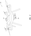
- Figure 2 illustrates further details of the aerial vehicle 100.
- the aerial vehicle 100 includes an irradiance sensing device 110 and an imaging device 120 for imaging a physical area or scene (i.e., a target).
- the irradiance sensing device 110 and the imaging device 120 may collect, store and/or output the obtained irradiance and image information.
- the aerial vehicle 100 may be any type of aerial vehicle, including any rotary or fixed wing aerial vehicle, and may be an unmanned vehicle (as shown in Figure 1 ) or manned aerial vehicle, such as an airplane or a drone. Additionally, the aerial vehicle 100 may be an autonomous vehicle, capable of autonomous flight (and autonomous acquisition of irradiance and image information), or may be a piloted vehicle (e.g., flown by a pilot in a manned vehicle, or by a remote pilot of an unmanned vehicle).
- an autonomous vehicle capable of autonomous flight (and autonomous acquisition of irradiance and image information)
- a piloted vehicle e.g., flown by a pilot in a manned vehicle, or by a remote pilot of an unmanned vehicle.
- the imaged target receives irradiance from a light source, such as the sun 108.
- the target may be one or more distinct objects (e.g., a single tree, a building, a pond, etc.), an area or scene (e.g., a portion of a forest, a portion of a field of crops, a portion of a lake, etc.) or any other target for which the acquisition of an image may be desired.
- the imaging device 120 may be a multispectral imaging device capable of acquiring spectral images of a target, and may include multiple imagers, with each such imager being tuned for capturing particular wavelengths of light that is reflected by the target.
- the imaging device 120 may be configured to capture reflected light in one or more of the ultraviolet, visible, near-infrared, and/or infrared regions of the electromagnetic spectrum.
- Images acquired by such multispectral imaging devices may be utilized to measure or determine different characteristics of the target, such as the chlorophyll content of a plant, an amount of leaf area per unit ground area, an amount or type of algae in a body of water, and the like.
- a processor is configured to determine a reflectance of the target based on image information of the target acquired by the imaging device 120.
- the imaging device 120 is mounted to the aerial vehicle 100 and oriented in any manner as may be desired.
- the imaging device 120 may be mounted to a lower surface of the aerial vehicle 100 and positioned such that images of ground-based targets may be obtained.
- the irradiance sensing device 110 may be mounted to an upper surface of the aerial device 100, and includes a plurality of photo sensors configured to simultaneously sense irradiance from a light source, such as the sun 108, at various different orientations with respect to the light source.
- a light source such as the sun 108
- the irradiance sensing device 110 senses irradiance at the same time as images are acquired by the imaging device 120, which enables normalization or compensation of the acquired images to account for variations in received irradiance by the imaged target.
- an image of a target acquired by the imaging device 120 on a cloudy day can be correlated to an image acquired of the same target on a cloudless day, by accounting for the differences in the irradiance sensed by the irradiance sensing device 110 at the time of acquiring each image.
- FIG. 3 illustrates the irradiance sensing device 110 in further detail, in accordance with one or more embodiments of the present disclosure.
- the irradiance sensing device 110 includes a plurality of photo sensors 112 arranged on different surfaces of a base 115.
- the base 115 includes a lower surface 114 that may be mounted, for example, to an upper surface of the aerial vehicle 100. Extending from the lower surface 114 is a plurality of inclined surfaces 116 on which the photo sensors 112 may be mounted.
- the base 115 may have a truncated square pyramid shape, with four inclined surfaces 116 extending between the lower surface 114 and a flat upper surface 118.
- One or more photo sensors 112 may be mounted on each of the inclined surfaces 116 and the upper surface 118.
- the photo sensors 112 may thus be oriented to receive and sense varying amounts or components (e.g., direct and scattered components) of irradiance from a light source such as the sun 108.
- the base 115 may have any shape or form that includes a plurality of surfaces on which photo sensors 112 may be mounted and configured to sense irradiance from differing orientations.
- the irradiance sensing device 110 may preferably include at least four, and in accordance with the claimed invention, includes five photo sensors 112. Accordingly, the base 115 may preferably include at least four, and in accordance with the claimed invention, five surfaces having different orientations for mounting the photo sensors 112.
- Each photo sensor 112 includes a housing 111 or some external packaging that houses electronic circuitry (such as one or more application specific integrated circuits, computer-readable memory and the like) for processing and/or storing received signals (e.g., signals indicative of the sensed irradiance), and a photo sensor surface 113 for sensing irradiance.
- electronic circuitry such as one or more application specific integrated circuits, computer-readable memory and the like
- received signals e.g., signals indicative of the sensed irradiance
- photo sensor surface 113 for sensing irradiance.
- Each of the photo sensors 112 may include one or more ports 117 for communicating signals (e.g., one or more signals indicative of the sensed irradiance) to or from the photo sensors 112.
- the photo sensors 112 may be coupled to a processor (e.g., by one or more electrical wires or cables coupled to the ports 117) that is included onboard the aerial vehicle 100.
- the processor may similarly be communicatively coupled to the imaging device 120. Accordingly, the processor may acquire the sensed irradiance by the photo sensors 112 at the same time as an image of a target is acquired by the imaging device 120.
- the irradiance sensed by the irradiance sensing device 110 may thus be correlated with the image that is simultaneously acquired by the imaging device 120.
- the photo sensors 112 may store the sensed irradiance information as it is acquired during a flight of the aerial vehicle 100.
- the imaging device 120 may store images acquired during the flight.
- the image and irradiance information may later be uploaded to a computing system, which may correlate the stored irradiance and image information based on the time of acquisition of such information, which may be provided through a time stamp or similar information that may be included with the irradiance and image information.
- the base 115 may be at least partially hollow or may otherwise include an inner cavity, which reduces the weight of the irradiance sensing device 110. Further, additional components of the aerial vehicle 100, such as any electrical or electronic components, may be housed within the inner cavity of the base 115. For example, a processor and/or any other circuitry may be included within the base 115 and may be communicatively coupled to the photo sensors 112 and/or the imaging device 120.
- an irradiance sensing device For irradiance sensing by an aerial vehicle, an irradiance sensing device should provide an instantaneous estimate of both the direct and scattered components, independent of sensor attitude estimates (e.g., which may be provided from an imprecise IMU) and large movements of the aerial vehicle itself. While a single sensor cannot provide such estimates, a multisensor array such as the irradiance sensing device 110 provided herein can.
- the direct and scattered components of solar irradiance at any particular time are determined based on the sensed irradiance simultaneously acquired by a plurality of photo sensors 112 having different orientations.
- a sensor body coordinate system is assumed that has a Z-axis oriented towards the current sun position.
- the incidence angle ⁇ between the sun and a sensor depends only on two angles (the azimuth angle and the zenith angle), since the irradiance is invariant under rotations around the Z-axis.
- the azimuth and zenith angles are treated as unknowns to be estimated along with the direct and scattered solar irradiance.
- Such a system is readily solvable by standard means, such as Newton's method or least squares.
- a system of five sensors (e.g., as shown in Figure 3 ) having the following configuration provides good results in simulation and allows a stable determination of all unknown quantities.
- this method may not suitably determine the components of irradiance.
- One such circumstance exists in the absence of any direct light, in which the number of independent equations collapses to just one.
- no meaningful results can be expected when the incidence angle becomes greater than 90 degrees for any photo sensor, a case which can be determined by use of an IMU. Note that in this case no particularly high accuracy from the IMU is required, as it is only needed to determine this special threshold.
- the irradiance sensing device 110 may have a known coordinate system, and a transformation exists and may be determined between the device coordinate system and the global coordinate system, as the position of the sun at any given time is known.
- irradiance sensed simultaneously by each of the photo sensors 112 of the irradiance sensing device 110 is utilized to determine (e.g., by a processor) the direct and scattered components of solar irradiance (as well as the incidence angle ⁇ , the azimuth angle ⁇ and the zenith angle ⁇ ) that is incident at a particular time on a target that may be imaged by the imaging device 120.
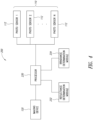
- Figure 4 is a block diagram illustrating a system 200 for estimating or determining irradiance, based on the sensed irradiance from a plurality of photo sensors (e.g., as sensed by the irradiance sensing device 110), and for determining the reflectance of an imaged target or object.
- the system 200 may include a processor 230 that is communicatively coupled to the imaging device 120 and the irradiance sensing device 110 (including photo sensors 1 to N).
- the processor 230 may be included onboard the aerial vehicle 100 (e.g., housed within a cavity in the base 115, or at any other location on the aerial vehicle 100). In other embodiments, the processor 230 may be included as part of a post-processing computer to which the irradiance sensing device 110 and/or the imaging device 120 may be coupled after an imaging session by the aerial vehicle 100. The post-processing computer may thus determine the components of the sensed irradiance based on the data collected and stored by the irradiance sensing device 110. Similarly, the imaging device 120 may capture and store data, which may later be provided to and processed by the processor 230.
- the processor 230 and/or instructions performed by the processor 230 may be located in the cloud, i.e., a remote distributed computing network that receives the collected data wirelessly from the imaging device 120 and the irradiance sensing device 110 or receives the data through a wired network once the imaging device 120 and irradiance sensing device 110 are coupled to a computer after the imaging session.
- a remote distributed computing network that receives the collected data wirelessly from the imaging device 120 and the irradiance sensing device 110 or receives the data through a wired network once the imaging device 120 and irradiance sensing device 110 are coupled to a computer after the imaging session.
- the processor 230 receives the sensed irradiance information from the irradiance sensing device 110 and the acquired image information from the imaging device 120.
- the processor 230 may access an irradiance determination module 234, which contains computer-readable instructions for determining the direct and scattered components of solar irradiance (and may further determine the incidence angle a, the azimuth angle ⁇ and the zenith angle ⁇ ) based on the simultaneously sensed irradiance information from the plurality of photo sensors 112, as described herein.
- the processor 230 provides the determined direct and scattered components of solar irradiance to a reflectance determination module 232, along with image information of a target that was acquired by the imaging device 120 at the same time that the irradiance information was acquired.
- the reflectance determination module 232 includes computer-readable instructions for determining the reflectance of the target based on the image information of the target (which may indicate, for example, an amount of light reflected by the target) and the determined components of irradiance at the time the image information was acquired. Accordingly, the determined reflectance of an imaged target is normalized or compensated to account for different irradiance levels that may be present at the time of imaging a target.
- a determined reflectance for a target based on an image of the target acquired on a cloudy day will be the same or substantially the same as the reflectance for that same target that is determined based on an image of the target that was acquired on a cloudless day.
- a compensation factor may thus be determined by the processor 230 (based on the determined components of irradiance) and may be applied by the reflectance determination module 232 for every image that is acquired by the imaging device 120, in order to accurately determine the reflectance of the imaged target, regardless of the lighting conditions at the time the image was acquired.
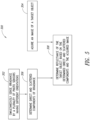
- Figure 5 is a flowchart 300 illustrating a method of the present disclosure.
- the method includes simultaneously sensing irradiance from a light source by an irradiance sensing device 110 including a plurality of photo sensors 112 having different orientations with respect to the light source.
- the photo sensors 112 may be arranged, for example, as shown in the irradiance sensing device 110 of Figure 3 .
- the photo sensors 112 may be included onboard an aerial vehicle 100, and the irradiance may thus be sensed while the aerial vehicle 100 is in flight.
- the method includes acquiring an image of a target object by an imaging device 120.
- the image may be acquired at the same time as the irradiance sensing device 110 senses irradiance, and the image and irradiance information may thus be correlated.
- the method includes determining direct and scattered components of the sensed irradiance. And at 308, the method includes determining the reflectance of the target object based on the determined direct and scattered components of the sensed irradiance, and the acquired image of the target object.
- This method thus provides inherently compensated or normalized reflectance measurements of a target, such as vegetation, that are independent of changes in irradiance from a variable light source (e.g., the sun), and does not require an IMU or calibration of the imaging device. The method may be performed for each image acquired by the imaging device 120.
- Reflectance is a property of materials and is generally defined as the fraction of incident irradiance that is reflected by a target.
- the reflectance properties of a material depend on the particular material and its physical and chemical state (e.g., moisture), as well as other properties such as surface texture and other properties that may be known in the relevant field.
- determining reflectance of one or more imaged targets may be desirable. For example, by measuring or determining the reflectance of a plant at different wavelengths, areas of stress in a crop may be identified. Moreover, determined changes in reflectance of surface features such as vegetation, soil, water and the like can be utilized to determine the development of disease in crops, growth of algae in a body of water, changes in the chemical properties of ground or soil, and so on.
- embodiments provided herein may be utilized in navigational applications, since the orientation of the irradiance sensing device 110 is determined with respect to the position of the sun. That is, the orientation of the irradiance sensing device 110 may be mapped to the global or horizontal coordinate system, as described above, which may thus be used for navigational purposes by any vehicle including the irradiance sensing device 110. Additionally, it will be appreciated that flight parameters of the aerial vehicle 100, including pitch, heading and roll, may be determined based on the irradiance sensed by the photo sensors 112 of the irradiance sensing device 110, and the determined components of the irradiance.
- the estimates of the components of the irradiance are instantaneous and the photo sensor attitudes are provided in the special solar coordinate system.
- the orientation of the irradiance sensing device 110 may be mapped to the global or horizontal coordinate system, as described herein.
- the determined photo sensor attitudes including, pitch, heading and roll information
- the special solar coordinate system may be mapped to the global or horizontal coordinate system for an indication of the aerial vehicle's 100 attitude with respect to the Earth.
- changes in the determined photo sensor pitch, heading and roll during flight may be utilized for navigational purposes.
Landscapes
- Physics & Mathematics (AREA)
- General Physics & Mathematics (AREA)
- Engineering & Computer Science (AREA)
- Spectroscopy & Molecular Physics (AREA)
- Life Sciences & Earth Sciences (AREA)
- Sustainable Development (AREA)
- Multimedia (AREA)
- Signal Processing (AREA)
- Computer Vision & Pattern Recognition (AREA)
- Remote Sensing (AREA)
- Quality & Reliability (AREA)
- Theoretical Computer Science (AREA)
- Radar, Positioning & Navigation (AREA)
- Electromagnetism (AREA)
- Investigating Or Analysing Materials By Optical Means (AREA)
- Photometry And Measurement Of Optical Pulse Characteristics (AREA)
- Business, Economics & Management (AREA)
- Spectrometry And Color Measurement (AREA)
- Health & Medical Sciences (AREA)
- Artificial Intelligence (AREA)
- Evolutionary Computation (AREA)
- Game Theory and Decision Science (AREA)
- Medical Informatics (AREA)
- Aviation & Aerospace Engineering (AREA)
- Automation & Control Theory (AREA)
Description
- The present disclosure is directed to estimating or determining irradiance using an irradiance sensing device having a plurality of photo sensors having different orientations.
- A common problem in radiometric remote sensing is the estimation of incident irradiance from the sun on arbitrary surfaces from the scattered and direct component of the sunlight. Traditionally, these components of sunlight are measured on the ground, using a shaded pyranometer for the scattered component and a pyrheliometer for the direct component. Both of these devices track the position of the sun during measurement. The pyrheliometer has a long tube that only allows direct light in and the tracking shading of the pyranometer blocks direct light, so that the instruments measure only the direct and scattered light, respectively. Both instruments have significant cost and are unsuitable for mounting on a small, rapidly moving platform such as a drone.
- A single conventional light sensor can be used to measure both components of sunlight, if the sensor attitude is well determined and the attitude is varied over time. However, while such a sensor can be mounted on a drone, the precise attitude estimates for a moving platform are difficult to obtain, or require costly sensors and are prone to significant errors, particularly under changing light conditions, e.g. due to partial cloud cover.
- Accordingly, in conventional remote sensing applications, such as multispectral imaging applications for determining the health of vegetation, ground-based calibration systems are typically employed for normalizing the effects of a variable light source (e.g., the sun) on multispectral images of a target. Such calibration systems commonly rely on the use of target calibration or reflectance panels having a known spectral reflectance that are placed in the field of view of a multispectral imaging device and can be used to calibrate the acquired image of the target. There are several drawbacks to such techniques, including that the calibration or reflectance panels are costly, cumbersome and do not accurately measure irradiance levels simultaneously with the acquired images.
- SASTRY S ET AL: "Attitude Control for a Micromechanical Flying Insect via Sensor Output Feedback", IEEE TRANSACTIONS ON ROBOTICS AND AUTOMATION, vol. 20, no. 1, 1 February 2004, discloses attitude stabilization strategies via output sensor feedback for micro aerial vehicles (MAVs). In order to compensate for the size and power limitations of MAVs, ocelli and halteres, the body orientation and rotation sensing mechanisms used by flying insects, are introduced. Attitude stabilization techniques based on these sensors are proposed and tested on an aerodynamic model for a micromechanical flying insect (MFI).
-
CN 101750068 A discloses an attitude sensor, and in particular, a sun sensor using a multi-channel light guide fiber as a light introducer and a method of measuring the position thereof. -
US 2016/0237745 A1 discloses a window shading control system and method thereof based on decomposed direct and diffuse solar radiations. -
US 2016/0232650 A1 discloses a method and system of calibrating a multispectral camera on an aerial vehicle. -
US 2013/0266221 A1 discloses an imaging processing method, image processing system, and image processing program. - In a first aspect of the present invention, there is provided a device according to
claim 1. - In a second aspect of the present invention, there is provided a method according to claim 8.
- The dependent claims define preferred embodiments.
- The present disclosure is directed to devices and methods for sensing irradiance from a light source, such as the sun, by an irradiance sensing device including a plurality of photo sensors arranged at differing orientations. By simultaneously sensing the irradiance with multiple photo sensors having different orientations, particular components of the irradiance, such as the direct and scattered components and the incidence angle, may be determined. These determined irradiance components may be used to compensate or normalize images of a target that are acquired at the same time by an imaging device. The irradiance sensing device and the imaging device may be carried on an aerial vehicle, such as a drone.
- The present disclosure provides a device that includes an aerial vehicle and an irradiance sensing device. The irradiance sensing device includes a base structure mounted to the aerial vehicle, and the base structure includes a plurality of surfaces. The irradiance sensing device further includes a plurality of photo sensors, with each of the photo sensors being arranged on a respective surface of the base structure and having different orientations.
- The present disclosure provides a method that includes: simultaneously sensing irradiance by a plurality of photo sensors, each of the photo sensors having a different sensing orientation; acquiring image information associated with a target object; determining, by a processor, direct and scattered components of the sensed irradiance; and determining a reflectance of the target object based on the determined direct and scattered components and the acquired image information.
- The present disclosure provides a method that includes: simultaneously sensing irradiance by a plurality of photo sensors positioned on an aerial vehicle, each of the photo sensors having a different sensing orientation; transmitting information indicative of the sensed irradiance from the plurality of photos sensors to a processor; and determining, by the processor, direct and scattered components of the irradiance.
- In the drawings, identical reference numbers identify similar elements. The sizes and relative positions of elements in the drawings are not necessarily drawn to scale.
-
Figure 1 is an illustration of an aerial vehicle for sensing irradiance and simultaneously obtaining an image of a target, in accordance with one or more embodiments of the present disclosure. -
Figure 2 is an illustration showing further details of the aerial vehicle ofFigure 1 . -
Figure 3 is an illustration of an irradiance sensing device, in accordance with one or more embodiments of the present disclosure. -
Figure 4 is a block diagram illustrating a system for estimating or determining irradiance, based on irradiance sensed from a plurality of photo sensors, and for determining the reflectance of an imaged object, in accordance with one or more embodiments of the present disclosure. -
Figure 5 is a flowchart illustrating a method of determining direct and scattered components of sensed irradiance, and determining reflectance of an imaged target based on the determined direct and scattered components, in accordance with one or more embodiments of the present disclosure. - The present disclosure is directed to systems and methods for measuring solar irradiance in radiometric remote sensing applications. Irradiance from a light source, such as the sun, may be simultaneously sensed by a plurality of photo sensors arranged at differing orientations on an irradiance sensing device. Components of the irradiance, such as the direct and scattered components and the incidence angle, may thus be determined, and utilized to compensate or normalize images of a target that are acquired at the same time by an imaging device.
-
Figure 1 illustrates anaerial vehicle 100 for sensing irradiance and simultaneously obtaining an image, for example, of a ground-based target, in accordance with one or more embodiments, andFigure 2 illustrates further details of theaerial vehicle 100. Referring toFigures 1 and2 , theaerial vehicle 100 includes anirradiance sensing device 110 and animaging device 120 for imaging a physical area or scene (i.e., a target). Theirradiance sensing device 110 and theimaging device 120 may collect, store and/or output the obtained irradiance and image information. - The
aerial vehicle 100 may be any type of aerial vehicle, including any rotary or fixed wing aerial vehicle, and may be an unmanned vehicle (as shown inFigure 1 ) or manned aerial vehicle, such as an airplane or a drone. Additionally, theaerial vehicle 100 may be an autonomous vehicle, capable of autonomous flight (and autonomous acquisition of irradiance and image information), or may be a piloted vehicle (e.g., flown by a pilot in a manned vehicle, or by a remote pilot of an unmanned vehicle). - The imaged target (e.g.,
trees 102,crops sun 108. The target may be one or more distinct objects (e.g., a single tree, a building, a pond, etc.), an area or scene (e.g., a portion of a forest, a portion of a field of crops, a portion of a lake, etc.) or any other target for which the acquisition of an image may be desired. - The
imaging device 120 may be a multispectral imaging device capable of acquiring spectral images of a target, and may include multiple imagers, with each such imager being tuned for capturing particular wavelengths of light that is reflected by the target. Theimaging device 120 may be configured to capture reflected light in one or more of the ultraviolet, visible, near-infrared, and/or infrared regions of the electromagnetic spectrum. - Images acquired by such multispectral imaging devices may be utilized to measure or determine different characteristics of the target, such as the chlorophyll content of a plant, an amount of leaf area per unit ground area, an amount or type of algae in a body of water, and the like. According to the invention, a processor is configured to determine a reflectance of the target based on image information of the target acquired by the
imaging device 120. - The
imaging device 120 is mounted to theaerial vehicle 100 and oriented in any manner as may be desired. For example, theimaging device 120 may be mounted to a lower surface of theaerial vehicle 100 and positioned such that images of ground-based targets may be obtained. - The
irradiance sensing device 110 may be mounted to an upper surface of theaerial device 100, and includes a plurality of photo sensors configured to simultaneously sense irradiance from a light source, such as thesun 108, at various different orientations with respect to the light source. - By simultaneously sensing irradiance by multiple photo sensors having different orientations, it is possible to determine particular characteristics of the light source, namely the direct and scattered components of solar irradiance, as well as an angle of incidence α of the solar irradiance. Moreover, the
irradiance sensing device 110 senses irradiance at the same time as images are acquired by theimaging device 120, which enables normalization or compensation of the acquired images to account for variations in received irradiance by the imaged target. For example, an image of a target acquired by theimaging device 120 on a cloudy day can be correlated to an image acquired of the same target on a cloudless day, by accounting for the differences in the irradiance sensed by theirradiance sensing device 110 at the time of acquiring each image. -
Figure 3 illustrates theirradiance sensing device 110 in further detail, in accordance with one or more embodiments of the present disclosure. Theirradiance sensing device 110 includes a plurality ofphoto sensors 112 arranged on different surfaces of abase 115. Thebase 115 includes alower surface 114 that may be mounted, for example, to an upper surface of theaerial vehicle 100. Extending from thelower surface 114 is a plurality ofinclined surfaces 116 on which thephoto sensors 112 may be mounted. As shown inFigure 3 , in one or more embodiments, thebase 115 may have a truncated square pyramid shape, with fourinclined surfaces 116 extending between thelower surface 114 and a flatupper surface 118. One ormore photo sensors 112 may be mounted on each of theinclined surfaces 116 and theupper surface 118. Thephoto sensors 112 may thus be oriented to receive and sense varying amounts or components (e.g., direct and scattered components) of irradiance from a light source such as thesun 108. - The base 115 may have any shape or form that includes a plurality of surfaces on which
photo sensors 112 may be mounted and configured to sense irradiance from differing orientations. Theirradiance sensing device 110 may preferably include at least four, and in accordance with the claimed invention, includes fivephoto sensors 112. Accordingly, thebase 115 may preferably include at least four, and in accordance with the claimed invention, five surfaces having different orientations for mounting thephoto sensors 112. - Each
photo sensor 112 includes ahousing 111 or some external packaging that houses electronic circuitry (such as one or more application specific integrated circuits, computer-readable memory and the like) for processing and/or storing received signals (e.g., signals indicative of the sensed irradiance), and aphoto sensor surface 113 for sensing irradiance. - Each of the
photo sensors 112 may include one ormore ports 117 for communicating signals (e.g., one or more signals indicative of the sensed irradiance) to or from thephoto sensors 112. In one or more embodiments, thephoto sensors 112 may be coupled to a processor (e.g., by one or more electrical wires or cables coupled to the ports 117) that is included onboard theaerial vehicle 100. The processor may similarly be communicatively coupled to theimaging device 120. Accordingly, the processor may acquire the sensed irradiance by thephoto sensors 112 at the same time as an image of a target is acquired by theimaging device 120. The irradiance sensed by theirradiance sensing device 110 may thus be correlated with the image that is simultaneously acquired by theimaging device 120. - Additionally or alternatively, the
photo sensors 112 may store the sensed irradiance information as it is acquired during a flight of theaerial vehicle 100. Similarly, theimaging device 120 may store images acquired during the flight. The image and irradiance information may later be uploaded to a computing system, which may correlate the stored irradiance and image information based on the time of acquisition of such information, which may be provided through a time stamp or similar information that may be included with the irradiance and image information. - The base 115 may be at least partially hollow or may otherwise include an inner cavity, which reduces the weight of the
irradiance sensing device 110. Further, additional components of theaerial vehicle 100, such as any electrical or electronic components, may be housed within the inner cavity of thebase 115. For example, a processor and/or any other circuitry may be included within thebase 115 and may be communicatively coupled to thephoto sensors 112 and/or theimaging device 120. - For irradiance sensing by an aerial vehicle, an irradiance sensing device should provide an instantaneous estimate of both the direct and scattered components, independent of sensor attitude estimates (e.g., which may be provided from an imprecise IMU) and large movements of the aerial vehicle itself. While a single sensor cannot provide such estimates, a multisensor array such as the
irradiance sensing device 110 provided herein can. - As will be demonstrated below, the direct and scattered components of solar irradiance at any particular time are determined based on the sensed irradiance simultaneously acquired by a plurality of
photo sensors 112 having different orientations. - For simplicity sake and without loss of generality, a sensor body coordinate system is assumed that has a Z-axis oriented towards the current sun position. In such a coordinate system, the incidence angle α between the sun and a sensor depends only on two angles (the azimuth angle and the zenith angle), since the irradiance is invariant under rotations around the Z-axis.
- Rather than trying to directly measure these angles, the azimuth and zenith angles are treated as unknowns to be estimated along with the direct and scattered solar irradiance. Thus in total, we aim to determine four unknowns from a set of five (or more) independent irradiance measurements, which will give us five (or more) non-linear equations. Such a system is readily solvable by standard means, such as Newton's method or least squares.
- A system of five sensors (e.g., as shown in
Figure 3 ) having the following configuration provides good results in simulation and allows a stable determination of all unknown quantities. - Note that the only inputs in this method are the known fixed photo sensor orientations and the measured irradiances. No assumptions about the time course of the direct and scattered irradiance are required and no attitudes need to be measured. The estimates of the components of the irradiance are instantaneous and as an added benefit, the photo sensor attitudes are provided in the special solar coordinate system.
- It is noted that there are some special circumstances in which this method may not suitably determine the components of irradiance. One such circumstance exists in the absence of any direct light, in which the number of independent equations collapses to just one. However this is a special case that can easily be identified, as in this case all photo sensor readings should be the same, and equal to the scattered irradiance. Also, no meaningful results can be expected when the incidence angle becomes greater than 90 degrees for any photo sensor, a case which can be determined by use of an IMU. Note that in this case no particularly high accuracy from the IMU is required, as it is only needed to determine this special threshold.
- In view of the above, the
irradiance sensing device 110 may have a known coordinate system, and a transformation exists and may be determined between the device coordinate system and the global coordinate system, as the position of the sun at any given time is known. - Accordingly, irradiance sensed simultaneously by each of the
photo sensors 112 of theirradiance sensing device 110 is utilized to determine (e.g., by a processor) the direct and scattered components of solar irradiance (as well as the incidence angle α, the azimuth angle φ and the zenith angle θ) that is incident at a particular time on a target that may be imaged by theimaging device 120. -
Figure 4 is a block diagram illustrating asystem 200 for estimating or determining irradiance, based on the sensed irradiance from a plurality of photo sensors (e.g., as sensed by the irradiance sensing device 110), and for determining the reflectance of an imaged target or object. Thesystem 200 may include aprocessor 230 that is communicatively coupled to theimaging device 120 and the irradiance sensing device 110 (includingphoto sensors 1 to N). - As noted previously herein, the
processor 230 may be included onboard the aerial vehicle 100 (e.g., housed within a cavity in thebase 115, or at any other location on the aerial vehicle 100). In other embodiments, theprocessor 230 may be included as part of a post-processing computer to which theirradiance sensing device 110 and/or theimaging device 120 may be coupled after an imaging session by theaerial vehicle 100. The post-processing computer may thus determine the components of the sensed irradiance based on the data collected and stored by theirradiance sensing device 110. Similarly, theimaging device 120 may capture and store data, which may later be provided to and processed by theprocessor 230. - Additionally, the
processor 230 and/or instructions performed by the processor 230 (e.g., for determining irradiance components, reflectance values, etc.) may be located in the cloud, i.e., a remote distributed computing network that receives the collected data wirelessly from theimaging device 120 and theirradiance sensing device 110 or receives the data through a wired network once theimaging device 120 andirradiance sensing device 110 are coupled to a computer after the imaging session. - The
processor 230 receives the sensed irradiance information from theirradiance sensing device 110 and the acquired image information from theimaging device 120. Theprocessor 230 may access anirradiance determination module 234, which contains computer-readable instructions for determining the direct and scattered components of solar irradiance (and may further determine the incidence angle a, the azimuth angle φ and the zenith angle θ) based on the simultaneously sensed irradiance information from the plurality ofphoto sensors 112, as described herein. - The
processor 230 provides the determined direct and scattered components of solar irradiance to areflectance determination module 232, along with image information of a target that was acquired by theimaging device 120 at the same time that the irradiance information was acquired. Thereflectance determination module 232 includes computer-readable instructions for determining the reflectance of the target based on the image information of the target (which may indicate, for example, an amount of light reflected by the target) and the determined components of irradiance at the time the image information was acquired. Accordingly, the determined reflectance of an imaged target is normalized or compensated to account for different irradiance levels that may be present at the time of imaging a target. For example, a determined reflectance for a target based on an image of the target acquired on a cloudy day will be the same or substantially the same as the reflectance for that same target that is determined based on an image of the target that was acquired on a cloudless day. - A compensation factor may thus be determined by the processor 230 (based on the determined components of irradiance) and may be applied by the
reflectance determination module 232 for every image that is acquired by theimaging device 120, in order to accurately determine the reflectance of the imaged target, regardless of the lighting conditions at the time the image was acquired. -
Figure 5 is aflowchart 300 illustrating a method of the present disclosure. At 302, the method includes simultaneously sensing irradiance from a light source by anirradiance sensing device 110 including a plurality ofphoto sensors 112 having different orientations with respect to the light source. Thephoto sensors 112 may be arranged, for example, as shown in theirradiance sensing device 110 ofFigure 3 . Thephoto sensors 112 may be included onboard anaerial vehicle 100, and the irradiance may thus be sensed while theaerial vehicle 100 is in flight. - At 304, the method includes acquiring an image of a target object by an
imaging device 120. The image may be acquired at the same time as theirradiance sensing device 110 senses irradiance, and the image and irradiance information may thus be correlated. - At 306, the method includes determining direct and scattered components of the sensed irradiance. And at 308, the method includes determining the reflectance of the target object based on the determined direct and scattered components of the sensed irradiance, and the acquired image of the target object. This method thus provides inherently compensated or normalized reflectance measurements of a target, such as vegetation, that are independent of changes in irradiance from a variable light source (e.g., the sun), and does not require an IMU or calibration of the imaging device. The method may be performed for each image acquired by the
imaging device 120. - As is well known, different materials reflect and absorb incident irradiance differently at different wavelengths. Thus, targets can be differentiated based on their spectral reflectance signatures in remotely sensed images. Reflectance is a property of materials and is generally defined as the fraction of incident irradiance that is reflected by a target. The reflectance properties of a material depend on the particular material and its physical and chemical state (e.g., moisture), as well as other properties such as surface texture and other properties that may be known in the relevant field.
- The various embodiments provided herein may be thus be utilized in a variety of applications in which determining reflectance of one or more imaged targets may be desirable. For example, by measuring or determining the reflectance of a plant at different wavelengths, areas of stress in a crop may be identified. Moreover, determined changes in reflectance of surface features such as vegetation, soil, water and the like can be utilized to determine the development of disease in crops, growth of algae in a body of water, changes in the chemical properties of ground or soil, and so on.
- Various other applications are contemplated by the present disclosure. For example, embodiments provided herein may be utilized in navigational applications, since the orientation of the
irradiance sensing device 110 is determined with respect to the position of the sun. That is, the orientation of theirradiance sensing device 110 may be mapped to the global or horizontal coordinate system, as described above, which may thus be used for navigational purposes by any vehicle including theirradiance sensing device 110. Additionally, it will be appreciated that flight parameters of theaerial vehicle 100, including pitch, heading and roll, may be determined based on the irradiance sensed by thephoto sensors 112 of theirradiance sensing device 110, and the determined components of the irradiance. As noted previously herein, the estimates of the components of the irradiance are instantaneous and the photo sensor attitudes are provided in the special solar coordinate system. Moreover, the orientation of theirradiance sensing device 110 may be mapped to the global or horizontal coordinate system, as described herein. Accordingly, the determined photo sensor attitudes (including, pitch, heading and roll information) provided in the special solar coordinate system may be mapped to the global or horizontal coordinate system for an indication of the aerial vehicle's 100 attitude with respect to the Earth. Additionally, changes in the determined photo sensor pitch, heading and roll during flight may be utilized for navigational purposes. - In the description, certain specific details are set forth in order to provide a thorough understanding of various embodiments of the disclosure. However, one skilled in the art will understand that the disclosure may be practiced without these specific details. In other instances, well-known structures have not been described in detail to avoid unnecessarily obscuring the descriptions of the embodiments of the present disclosure.
- Unless the context requires otherwise, throughout the specification and claims that follow, the word "comprise" and variations thereof, such as "comprises" and "comprising," are to be construed in an open, inclusive sense, that is, as "including, but not limited to."
- Reference throughout this specification to "one embodiment" or "an embodiment" means that a particular feature, structure or characteristic described in connection with the embodiment is included in at least one embodiment. Thus, the appearances of the phrases "in one embodiment" or "in an embodiment" in various places throughout this specification are not necessarily all referring to the same embodiment. Furthermore, the particular features, structures, or characteristics may be combined in any suitable manner in one or more embodiments.
- As used in this specification and the appended claims, the singular forms "a," "an," and "the" include plural referents unless the content clearly dictates otherwise. It should also be noted that the term "or" is generally employed in its sense including "and/or" unless the content clearly dictates otherwise.
- The invention is defined by the appended claims.
Claims (13)
- A device, comprising:an aerial vehicle (100); andan irradiance sensing device (110) including:a base structure (115) mounted to the aerial vehicle (100), the base structure (115) including five surfaces (116, 118), andfive photo sensors (112) respectively arranged on the surfaces of the base structure (115) and having different orientations with respect to each other, wherein the five photo sensors (112) are configured to simultaneously sense irradiance from a light source, and to output signals indicative of the sensed irradiance, andwherein the device further comprises a processor (230) coupled to the five photo sensors (112) and configured to receive the output signals and to determine a direct component and a scattered component of the sensed irradiance, and an azimuth and a zenith angle of the light source in a sensor body coordinate system based on the orientation of the photo sensors and the sensed irradiance,wherein the direct component and the scattered component of the sensed irradiance, and the azimuth and the zenith angle of the light source are determined by solving at least five non-linear equations formed from a set of at least five independent irradiance measurements,the device further comprising an imaging device (120) mounted to the aerial vehicle (100), wherein the processor (230) is coupled to the irradiance sensing device and the imaging device, the processor being configured to determine a reflectance of a target based on image information of the target acquired by the imaging device and the determined components of irradiance at the time the image information was acquired, and normalizing or compensating the determined reflectance to account for different irradiance levels at the time of imaging the target.
- The device of claim 1 wherein the five surfaces of the base structure (115) includes a lower surface (114), an upper surface (118) and a plurality of inclined surfaces (116) extending between the lower and upper surfaces.
- The device of claim 2 wherein the five photo sensors are arranged on the upper and inclined surfaces (116, 118) of the base structure.
- The device of claim 3 wherein the inclined surfaces (116) of the base structure (115) include four inclined surfaces (116), and the five photo sensors (112) are arranged on the four inclined surfaces (116) and the upper surface (118).
- The device of claim 1 wherein the imaging device (120) is a multispectral imaging device.
- The device of claim 1 wherein the aerial vehicle (100) is an unmanned aerial vehicle
- The device of claim 1, wherein the base structure (115) includes an inner cavity housing one or more electrical components of the device.
- A method, comprising:simultaneously sensing irradiance by five photo sensors (112) positioned on an aerial vehicle (100), each of the photo sensors (112) having a different sensing orientation;transmitting information indicative of the sensed irradiance from the five photos sensors (112) to a processor (230);determining, by the processor (230), direct and scattered components of the irradiance, and an azimuth and a zenith angle of the light source in a sensor body coordinate system based on the orientation of the photo sensors and the sensed irradiance, wherein the direct component and the scattered component of the sensed irradiance, and the azimuth and the zenith angle of the light source are determined by solving at least five non-linear equations formed from a set of at least five independent irradiance measurements; anddetermining, by the processor (230), a reflectance of a target based on image information of the target acquired by an imaging device and the determined components of irradiance at the time the image information was acquired, and normalizing or compensating the determined reflectance to account for different irradiance levels at the time of imaging the target.
- The method of claim 8, further comprising:
determining, by the processor (230), at least one of pitch, heading and roll of the aerial vehicle based on the simultaneously sensed irradiance by the five photo sensors having a different sensing orientation. - The method of claim 9, further comprising:
navigating a flight of the aerial vehicle based on the determined at least one of pitch, heading and roll. - The method of claim 8, further comprising correlating the sensed irradiance with the image information at a time the image information is acquired
- The method of claim 8, further comprising determining, by the processor (230), an incidence angle of the irradiance.
- The method of claim 8, wherein the target object includes a plant, the method further comprising:
determining a state of health of the plant based on the determined reflectance of the plant.
Applications Claiming Priority (2)
| Application Number | Priority Date | Filing Date | Title |
|---|---|---|---|
| US201762447273P | 2017-01-17 | 2017-01-17 | |
| PCT/US2017/066524 WO2018136175A1 (en) | 2017-01-17 | 2017-12-14 | Multi-sensor irradiance estimation |
Publications (3)
| Publication Number | Publication Date |
|---|---|
| EP3571480A1 EP3571480A1 (en) | 2019-11-27 |
| EP3571480A4 EP3571480A4 (en) | 2021-02-24 |
| EP3571480B1 true EP3571480B1 (en) | 2024-12-11 |
Family
ID=62908696
Family Applications (1)
| Application Number | Title | Priority Date | Filing Date |
|---|---|---|---|
| EP17892899.0A Active EP3571480B1 (en) | 2017-01-17 | 2017-12-14 | Aerial vehicle comprising irradiance sensor and imaging device |
Country Status (8)
| Country | Link |
|---|---|
| US (1) | US11290623B2 (en) |
| EP (1) | EP3571480B1 (en) |
| JP (1) | JP7321093B2 (en) |
| CN (2) | CN110291368A (en) |
| DK (1) | DK3571480T3 (en) |
| ES (1) | ES3023946T3 (en) |
| FI (1) | FI3571480T3 (en) |
| WO (1) | WO2018136175A1 (en) |
Families Citing this family (12)
| Publication number | Priority date | Publication date | Assignee | Title |
|---|---|---|---|---|
| WO2020190952A1 (en) * | 2019-03-18 | 2020-09-24 | The Climate Corporation | System and method for automatic control of exposure time in an imaging instrument |
| JP6798073B2 (en) * | 2019-06-04 | 2020-12-09 | エスゼット ディージェイアイ テクノロジー カンパニー リミテッドSz Dji Technology Co.,Ltd | Mobile body and sensor unit |
| US20220099483A1 (en) * | 2019-06-25 | 2022-03-31 | Michael Gostein | Measuring Direct, Diffuse, Global, and/or Ground-Reflected Solar Irradiance Using an Array of Irradiance Sensors |
| US11650103B2 (en) | 2019-06-25 | 2023-05-16 | Michael Gostein | Measuring direct, diffuse, or global solar irradiance using multiple irradiance sensors |
| GB201917600D0 (en) | 2019-12-02 | 2020-01-15 | Univ Of Essex Enterprises Limited | Improved reflectance measurement |
| CN112577595B (en) * | 2020-09-18 | 2023-01-20 | 临沂大学 | Three-dimensional light intensity sensing system, three-dimensional sensing method and unmanned aerial vehicle light intensity sensor |
| JP7069503B2 (en) * | 2020-10-05 | 2022-05-18 | エスゼット ディージェイアイ テクノロジー カンパニー リミテッド | Aircraft and sensor unit |
| US12055434B2 (en) | 2021-04-14 | 2024-08-06 | Micasense, Inc. | Diffuser for irradiance sensor including diffuser protruding from exterior surface |
| CN114402836A (en) * | 2021-12-28 | 2022-04-29 | 珠海华宜生态科技有限公司 | Illumination adjusting method and system for tomato cultivation in high-temperature and high-humidity environment |
| WO2024083729A1 (en) | 2022-10-17 | 2024-04-25 | ams Sensors Germany GmbH | Arial device for moisture measurements of soil, system and method |
| CN121364010A (en) * | 2024-07-19 | 2026-01-20 | 中国农业科学院农业资源与农业区划研究所 | Multispectral imaging sensor radiation calibration method and multispectral imaging sensor radiation calibration system |
| CN120467499B (en) * | 2025-07-09 | 2025-10-28 | 浙江大学 | Illuminance monitoring method and device based on aircraft |
Family Cites Families (31)
| Publication number | Priority date | Publication date | Assignee | Title |
|---|---|---|---|---|
| JPS5334654B2 (en) * | 1974-09-27 | 1978-09-21 | ||
| JPS5910806A (en) * | 1982-07-09 | 1984-01-20 | Akita Netsuken:Kk | System for observing direction and quantity of sunshine |
| JPS6273108A (en) * | 1985-09-27 | 1987-04-03 | Nissan Motor Co Ltd | Sunshine-state detector for vehicle |
| SE459529B (en) * | 1987-11-27 | 1989-07-10 | Foersvarets Forskningsanstalt | SET TO DETECT RADIATION AND MAKE IT AN APPROACH AND A DETECTOR'S ARRANGEMENT BEFORE IMPLEMENTING THE SET |
| JPH0352208U (en) * | 1989-09-29 | 1991-05-21 | ||
| GB9719614D0 (en) | 1997-09-10 | 1997-11-19 | Wood John | Solar radiation sensor |
| JP3837552B2 (en) | 2003-07-08 | 2006-10-25 | 国立大学法人名古屋大学 | Mobile optical environment measurement device |
| JP2006314215A (en) | 2005-05-10 | 2006-11-24 | National Agriculture & Food Research Organization | Growth degree measuring device for mobile equipment |
| DE102005046878A1 (en) * | 2005-09-29 | 2007-04-12 | Katz, Elisabeth | Device and method for rapid or online determination of the components of a two-component or multi-component system |
| JP2009210280A (en) | 2008-02-29 | 2009-09-17 | Toyama Univ | Azimuth sensor device |
| US20140118526A1 (en) * | 2012-10-30 | 2014-05-01 | Gary Edwin Sutton | Curvilinear sensor system |
| IL201682A0 (en) * | 2009-10-22 | 2010-11-30 | Bluebird Aero Systems Ltd | Imaging system for uav |
| CN101750068B (en) * | 2009-12-31 | 2011-10-05 | 苏州大学 | A solar sensor and its measuring method |
| US9686122B2 (en) * | 2010-05-10 | 2017-06-20 | Locus Energy, Inc. | Methods for orientation and tilt identification of photovoltaic systems and solar irradiance sensors |
| TWI408346B (en) * | 2010-05-10 | 2013-09-11 | Univ Nat Formosa | Incident solar power detecting method, apparatus and application thereof |
| JP5950117B2 (en) | 2010-12-24 | 2016-07-13 | 日本電気株式会社 | Image processing method, image processing system, and image processing program |
| US8796604B2 (en) * | 2011-11-21 | 2014-08-05 | General Electric Company | Apparatus having a controllable filter matrix to selectively acquire different components of solar irradiance |
| US20140022381A1 (en) | 2012-07-17 | 2014-01-23 | Tetracam, Inc. | Radiometric multi-spectral or hyperspectral camera array using matched area sensors and a calibrated ambient light collection device |
| WO2014152855A2 (en) * | 2013-03-14 | 2014-09-25 | Geerds Joergen | Camera system |
| WO2015088618A2 (en) | 2013-09-26 | 2015-06-18 | Konica Minolta Laboratory U.S.A., Inc. | Method and system of calibrating a multispectral camera on an aerial vehicle |
| WO2015049626A1 (en) * | 2013-10-03 | 2015-04-09 | Koninklijke Philips N.V. | A window shading control system and method thereof based on decomposed direct and diffuse solar radiations |
| CN104006879B (en) * | 2014-06-11 | 2016-01-20 | 河海大学常州校区 | Portable solar radiation tester and method of testing |
| US20150367957A1 (en) * | 2014-06-18 | 2015-12-24 | Aai Corporation | Providing visibility to a vehicle's environment via a set of cameras which is conformal to the vehicle |
| CN204037916U (en) * | 2014-06-30 | 2014-12-24 | 中国航天空气动力技术研究院 | A kind of low radar scattering cross section photoelectric nacelle |
| US9470579B2 (en) * | 2014-09-08 | 2016-10-18 | SlantRange, Inc. | System and method for calibrating imaging measurements taken from aerial vehicles |
| TWI727931B (en) * | 2014-09-29 | 2021-05-21 | 美商唯景公司 | Combi-sensor systems |
| US10209181B2 (en) * | 2015-05-21 | 2019-02-19 | C-Dax Limited | Plant matter sensor to determine health and/or nutritional content based on reflected signals at vertically displaced points on the plant matter |
| US9415870B1 (en) * | 2015-09-02 | 2016-08-16 | Amazon Technologies, Inc. | Unmanned aerial vehicle motor driving randomization and feedback for noise abatement |
| CN105890748A (en) * | 2016-04-07 | 2016-08-24 | 河海大学常州校区 | Intelligent mobile phone APP-based portable irradiation test device and method |
| EP3255397B1 (en) * | 2016-06-06 | 2023-02-22 | ams International AG | Optical sensor device |
| US10979607B2 (en) * | 2016-07-20 | 2021-04-13 | Apple Inc. | Camera apparatus and methods |
-
2017
- 2017-12-14 JP JP2019529189A patent/JP7321093B2/en active Active
- 2017-12-14 FI FIEP17892899.0T patent/FI3571480T3/en active
- 2017-12-14 ES ES17892899T patent/ES3023946T3/en active Active
- 2017-12-14 CN CN201780083888.1A patent/CN110291368A/en active Pending
- 2017-12-14 DK DK17892899.0T patent/DK3571480T3/en active
- 2017-12-14 CN CN202511547456.4A patent/CN121677917A/en active Pending
- 2017-12-14 WO PCT/US2017/066524 patent/WO2018136175A1/en not_active Ceased
- 2017-12-14 EP EP17892899.0A patent/EP3571480B1/en active Active
-
2018
- 2018-07-17 US US16/037,952 patent/US11290623B2/en active Active
Also Published As
| Publication number | Publication date |
|---|---|
| ES3023946T3 (en) | 2025-06-03 |
| EP3571480A4 (en) | 2021-02-24 |
| JP7321093B2 (en) | 2023-08-04 |
| US11290623B2 (en) | 2022-03-29 |
| WO2018136175A1 (en) | 2018-07-26 |
| FI3571480T3 (en) | 2025-03-14 |
| JP2020515809A (en) | 2020-05-28 |
| EP3571480A1 (en) | 2019-11-27 |
| US20180343367A1 (en) | 2018-11-29 |
| CN110291368A (en) | 2019-09-27 |
| DK3571480T3 (en) | 2025-03-03 |
| CN121677917A (en) | 2026-03-17 |
Similar Documents
| Publication | Publication Date | Title |
|---|---|---|
| US11290623B2 (en) | Multi-sensor irradiance estimation | |
| Liang et al. | Close-range remote sensing of forests: The state of the art, challenges, and opportunities for systems and data acquisitions | |
| Daponte et al. | A review on the use of drones for precision agriculture | |
| US12279028B2 (en) | Image sensor and thermal camera device, system and method | |
| Vasudevan et al. | Precision farming using unmanned aerial and ground vehicles | |
| US10339639B2 (en) | Method and system of calibrating a multispectral camera on an aerial vehicle | |
| Agüera et al. | Measuring sunflower nitrogen status from an unmanned aerial vehicle-based system and an on the ground device | |
| Ramírez-Cuesta et al. | Impact of the spatial resolution on the energy balance components on an open-canopy olive orchard | |
| Herrero-Huerta et al. | Vicarious radiometric calibration of a multispectral sensor from an aerial trike applied to precision agriculture | |
| Stark et al. | An analysis of the effect of the bidirectional reflectance distribution function on remote sensing imagery accuracy from small unmanned aircraft systems | |
| Bareth et al. | Comparison of uncalibrated RGBVI with spectrometer-based NDVI derived from UAV sensing systems on field scale | |
| Honkavaara et al. | Autonomous hyperspectral UAS photogrammetry for environmental monitoring applications | |
| Blanco‐Sacristán et al. | UAV RGB, thermal infrared and multispectral imagery used to investigate the control of terrain on the spatial distribution of dryland biocrust | |
| Sadenova et al. | Study of unmanned aerial vehicle sensors for practical remote application of earth sensing in agriculture | |
| Sankararao et al. | Workflow and calibration of airborne hyperspectral imaging system | |
| Selsam et al. | Acquisition and automated rectification of high-resolution RGB and near-IR aerial photographs to estimate plant biomass and surface topography in arid agro-ecosystems | |
| Jimenez Soler et al. | Validation and calibration of a high resolution sensor in unmanned aerial vehicles for producing images in the IR range utilizable in precision agriculture | |
| KR102324228B1 (en) | Drone basede bidirectional reflectance distribution function measurement method and system | |
| Jensen et al. | Calibrating thermal imagery from an unmanned aerial system-AggieAir | |
| Villareal et al. | Winter wheat crop height estimation using small unmanned aerial system (sUAS). | |
| Tsouvaltsidis et al. | Remote spectral imaging using a low cost UAV system | |
| Izere | Plant height estimation using RTK-GNSS enabled unmanned aerial vehicle (UAV) photogrammetry | |
| Maguire | An evaluation of unmanned aerial system multispectral and thermal infrared data as information for agricultural crop and irrigation management | |
| Fischer et al. | Bidirectional reflectance distribution function modeling considerations in small unmanned multispectral systems | |
| Krapez et al. | Combined airborne thermography and visible-to-near infrared reflectance measurement for soil moisture mapping |
Legal Events
| Date | Code | Title | Description |
|---|---|---|---|
| STAA | Information on the status of an ep patent application or granted ep patent |
Free format text: STATUS: THE INTERNATIONAL PUBLICATION HAS BEEN MADE |
|
| PUAI | Public reference made under article 153(3) epc to a published international application that has entered the european phase |
Free format text: ORIGINAL CODE: 0009012 |
|
| STAA | Information on the status of an ep patent application or granted ep patent |
Free format text: STATUS: REQUEST FOR EXAMINATION WAS MADE |
|
| 17P | Request for examination filed |
Effective date: 20190617 |
|
| AK | Designated contracting states |
Kind code of ref document: A1 Designated state(s): AL AT BE BG CH CY CZ DE DK EE ES FI FR GB GR HR HU IE IS IT LI LT LU LV MC MK MT NL NO PL PT RO RS SE SI SK SM TR |
|
| AX | Request for extension of the european patent |
Extension state: BA ME |
|
| DAV | Request for validation of the european patent (deleted) | ||
| DAX | Request for extension of the european patent (deleted) | ||
| RIC1 | Information provided on ipc code assigned before grant |
Ipc: G01J 3/02 20060101ALI20200908BHEP Ipc: G01J 3/00 20060101ALI20200908BHEP Ipc: G01J 3/28 20060101AFI20200908BHEP Ipc: G01S 5/16 20060101ALI20200908BHEP Ipc: H01L 27/00 20060101ALI20200908BHEP |
|
| A4 | Supplementary search report drawn up and despatched |
Effective date: 20210125 |
|
| RIC1 | Information provided on ipc code assigned before grant |
Ipc: H01L 27/00 20060101ALI20210119BHEP Ipc: G01J 1/02 20060101ALI20210119BHEP Ipc: G01J 3/00 20060101ALI20210119BHEP Ipc: G01J 3/02 20060101ALI20210119BHEP Ipc: G01J 1/42 20060101ALI20210119BHEP Ipc: G01J 3/28 20060101AFI20210119BHEP Ipc: G01S 5/16 20060101ALI20210119BHEP |
|
| STAA | Information on the status of an ep patent application or granted ep patent |
Free format text: STATUS: EXAMINATION IS IN PROGRESS |
|
| 17Q | First examination report despatched |
Effective date: 20230203 |
|
| REG | Reference to a national code |
Ref legal event code: R079 Ipc: G01S0003784000 Ref country code: DE Ref legal event code: R079 Ref document number: 602017086763 Country of ref document: DE Free format text: PREVIOUS MAIN CLASS: G01J0003280000 Ipc: G01S0003784000 |
|
| GRAP | Despatch of communication of intention to grant a patent |
Free format text: ORIGINAL CODE: EPIDOSNIGR1 |
|
| STAA | Information on the status of an ep patent application or granted ep patent |
Free format text: STATUS: GRANT OF PATENT IS INTENDED |
|
| RIC1 | Information provided on ipc code assigned before grant |
Ipc: G01J 1/02 20060101ALI20240424BHEP Ipc: G01J 1/42 20060101ALI20240424BHEP Ipc: G01J 3/02 20060101ALI20240424BHEP Ipc: B64U 101/30 20230101ALI20240424BHEP Ipc: G01S 3/784 20060101AFI20240424BHEP |
|
| INTG | Intention to grant announced |
Effective date: 20240513 |
|
| GRAJ | Information related to disapproval of communication of intention to grant by the applicant or resumption of examination proceedings by the epo deleted |
Free format text: ORIGINAL CODE: EPIDOSDIGR1 |
|
| STAA | Information on the status of an ep patent application or granted ep patent |
Free format text: STATUS: EXAMINATION IS IN PROGRESS |
|
| GRAP | Despatch of communication of intention to grant a patent |
Free format text: ORIGINAL CODE: EPIDOSNIGR1 |
|
| STAA | Information on the status of an ep patent application or granted ep patent |
Free format text: STATUS: GRANT OF PATENT IS INTENDED |
|
| INTC | Intention to grant announced (deleted) | ||
| INTG | Intention to grant announced |
Effective date: 20240703 |
|
| GRAS | Grant fee paid |
Free format text: ORIGINAL CODE: EPIDOSNIGR3 |
|
| GRAA | (expected) grant |
Free format text: ORIGINAL CODE: 0009210 |
|
| STAA | Information on the status of an ep patent application or granted ep patent |
Free format text: STATUS: THE PATENT HAS BEEN GRANTED |
|
| AK | Designated contracting states |
Kind code of ref document: B1 Designated state(s): AL AT BE BG CH CY CZ DE DK EE ES FI FR GB GR HR HU IE IS IT LI LT LU LV MC MK MT NL NO PL PT RO RS SE SI SK SM TR |
|
| REG | Reference to a national code |
Ref country code: GB Ref legal event code: FG4D |
|
| REG | Reference to a national code |
Ref country code: CH Ref legal event code: EP |
|
| REG | Reference to a national code |
Ref country code: DE Ref legal event code: R096 Ref document number: 602017086763 Country of ref document: DE |
|
| REG | Reference to a national code |
Ref country code: IE Ref legal event code: FG4D |
|
| REG | Reference to a national code |
Ref country code: DK Ref legal event code: T3 Effective date: 20250227 |
|
| REG | Reference to a national code |
Ref country code: FI Ref legal event code: FGE |
|
| REG | Reference to a national code |
Ref country code: SE Ref legal event code: TRGR |
|
| REG | Reference to a national code |
Ref country code: NL Ref legal event code: FP |
|
| REG | Reference to a national code |
Ref country code: LT Ref legal event code: MG9D |
|
| PG25 | Lapsed in a contracting state [announced via postgrant information from national office to epo] |
Ref country code: HR Free format text: LAPSE BECAUSE OF FAILURE TO SUBMIT A TRANSLATION OF THE DESCRIPTION OR TO PAY THE FEE WITHIN THE PRESCRIBED TIME-LIMIT Effective date: 20241211 |
|
| PG25 | Lapsed in a contracting state [announced via postgrant information from national office to epo] |
Ref country code: BG Free format text: LAPSE BECAUSE OF FAILURE TO SUBMIT A TRANSLATION OF THE DESCRIPTION OR TO PAY THE FEE WITHIN THE PRESCRIBED TIME-LIMIT Effective date: 20241211 |
|
| PG25 | Lapsed in a contracting state [announced via postgrant information from national office to epo] |
Ref country code: LV Free format text: LAPSE BECAUSE OF FAILURE TO SUBMIT A TRANSLATION OF THE DESCRIPTION OR TO PAY THE FEE WITHIN THE PRESCRIBED TIME-LIMIT Effective date: 20241211 Ref country code: GR Free format text: LAPSE BECAUSE OF FAILURE TO SUBMIT A TRANSLATION OF THE DESCRIPTION OR TO PAY THE FEE WITHIN THE PRESCRIBED TIME-LIMIT Effective date: 20250312 |
|
| PG25 | Lapsed in a contracting state [announced via postgrant information from national office to epo] |
Ref country code: RS Free format text: LAPSE BECAUSE OF FAILURE TO SUBMIT A TRANSLATION OF THE DESCRIPTION OR TO PAY THE FEE WITHIN THE PRESCRIBED TIME-LIMIT Effective date: 20250311 |
|
| REG | Reference to a national code |
Ref country code: DE Ref legal event code: R081 Ref document number: 602017086763 Country of ref document: DE Owner name: AGEAGLE AERIAL, INC. (N.D. GES. D. STAATES NEV, US Free format text: FORMER OWNER: MICASENSE, INC., SEATTLE, WA, US |
|
| REG | Reference to a national code |
Ref country code: ES Ref legal event code: FG2A Ref document number: 3023946 Country of ref document: ES Kind code of ref document: T3 Effective date: 20250603 |
|
| RAP2 | Party data changed (patent owner data changed or rights of a patent transferred) |
Owner name: AGEAGLE AERIAL, INC. |
|
| REG | Reference to a national code |
Ref country code: GB Ref legal event code: 732E Free format text: REGISTERED BETWEEN 20250529 AND 20250604 |
|
| PG25 | Lapsed in a contracting state [announced via postgrant information from national office to epo] |
Ref country code: SM Free format text: LAPSE BECAUSE OF FAILURE TO SUBMIT A TRANSLATION OF THE DESCRIPTION OR TO PAY THE FEE WITHIN THE PRESCRIBED TIME-LIMIT Effective date: 20241211 |
|
| REG | Reference to a national code |
Ref country code: BE Ref legal event code: PD Owner name: AGEAGLE AERIAL, INC.; US Free format text: DETAILS ASSIGNMENT: CHANGE OF OWNER(S), MERGE; FORMER OWNER NAME: MICASENSE, INC. Effective date: 20250407 |
|
| PG25 | Lapsed in a contracting state [announced via postgrant information from national office to epo] |
Ref country code: PL Free format text: LAPSE BECAUSE OF FAILURE TO SUBMIT A TRANSLATION OF THE DESCRIPTION OR TO PAY THE FEE WITHIN THE PRESCRIBED TIME-LIMIT Effective date: 20241211 |
|
| PG25 | Lapsed in a contracting state [announced via postgrant information from national office to epo] |
Ref country code: IS Free format text: LAPSE BECAUSE OF FAILURE TO SUBMIT A TRANSLATION OF THE DESCRIPTION OR TO PAY THE FEE WITHIN THE PRESCRIBED TIME-LIMIT Effective date: 20250411 |
|
| PG25 | Lapsed in a contracting state [announced via postgrant information from national office to epo] |
Ref country code: PT Free format text: LAPSE BECAUSE OF FAILURE TO SUBMIT A TRANSLATION OF THE DESCRIPTION OR TO PAY THE FEE WITHIN THE PRESCRIBED TIME-LIMIT Effective date: 20250411 |
|
| PG25 | Lapsed in a contracting state [announced via postgrant information from national office to epo] |
Ref country code: EE Free format text: LAPSE BECAUSE OF FAILURE TO SUBMIT A TRANSLATION OF THE DESCRIPTION OR TO PAY THE FEE WITHIN THE PRESCRIBED TIME-LIMIT Effective date: 20241211 |
|
| PG25 | Lapsed in a contracting state [announced via postgrant information from national office to epo] |
Ref country code: RO Free format text: LAPSE BECAUSE OF FAILURE TO SUBMIT A TRANSLATION OF THE DESCRIPTION OR TO PAY THE FEE WITHIN THE PRESCRIBED TIME-LIMIT Effective date: 20241211 |
|
| PG25 | Lapsed in a contracting state [announced via postgrant information from national office to epo] |
Ref country code: SK Free format text: LAPSE BECAUSE OF FAILURE TO SUBMIT A TRANSLATION OF THE DESCRIPTION OR TO PAY THE FEE WITHIN THE PRESCRIBED TIME-LIMIT Effective date: 20241211 |
|
| PG25 | Lapsed in a contracting state [announced via postgrant information from national office to epo] |
Ref country code: CZ Free format text: LAPSE BECAUSE OF FAILURE TO SUBMIT A TRANSLATION OF THE DESCRIPTION OR TO PAY THE FEE WITHIN THE PRESCRIBED TIME-LIMIT Effective date: 20241211 |
|
| PG25 | Lapsed in a contracting state [announced via postgrant information from national office to epo] |
Ref country code: IT Free format text: LAPSE BECAUSE OF FAILURE TO SUBMIT A TRANSLATION OF THE DESCRIPTION OR TO PAY THE FEE WITHIN THE PRESCRIBED TIME-LIMIT Effective date: 20241211 |
|
| PG25 | Lapsed in a contracting state [announced via postgrant information from national office to epo] |
Ref country code: LU Free format text: LAPSE BECAUSE OF NON-PAYMENT OF DUE FEES Effective date: 20241214 |
|
| REG | Reference to a national code |
Ref country code: DE Ref legal event code: R097 Ref document number: 602017086763 Country of ref document: DE |
|
| PG25 | Lapsed in a contracting state [announced via postgrant information from national office to epo] |
Ref country code: MC Free format text: LAPSE BECAUSE OF FAILURE TO SUBMIT A TRANSLATION OF THE DESCRIPTION OR TO PAY THE FEE WITHIN THE PRESCRIBED TIME-LIMIT Effective date: 20241211 |
|
| PLBE | No opposition filed within time limit |
Free format text: ORIGINAL CODE: 0009261 |
|
| STAA | Information on the status of an ep patent application or granted ep patent |
Free format text: STATUS: NO OPPOSITION FILED WITHIN TIME LIMIT |
|
| PG25 | Lapsed in a contracting state [announced via postgrant information from national office to epo] |
Ref country code: IE Free format text: LAPSE BECAUSE OF NON-PAYMENT OF DUE FEES Effective date: 20241214 |
|
| REG | Reference to a national code |
Ref country code: CH Ref legal event code: L10 Free format text: ST27 STATUS EVENT CODE: U-0-0-L10-L00 (AS PROVIDED BY THE NATIONAL OFFICE) Effective date: 20251022 |
|
| 26N | No opposition filed |
Effective date: 20250912 |
|
| REG | Reference to a national code |
Ref country code: CH Ref legal event code: U11 Free format text: ST27 STATUS EVENT CODE: U-0-0-U10-U11 (AS PROVIDED BY THE NATIONAL OFFICE) Effective date: 20260101 |
|
| PGFP | Annual fee paid to national office [announced via postgrant information from national office to epo] |
Ref country code: GB Payment date: 20251229 Year of fee payment: 9 |
|
| PGFP | Annual fee paid to national office [announced via postgrant information from national office to epo] |
Ref country code: NO Payment date: 20251231 Year of fee payment: 9 |
|
| PGFP | Annual fee paid to national office [announced via postgrant information from national office to epo] |
Ref country code: AT Payment date: 20251230 Year of fee payment: 9 |
|
| PGFP | Annual fee paid to national office [announced via postgrant information from national office to epo] |
Ref country code: FI Payment date: 20251226 Year of fee payment: 9 Ref country code: DK Payment date: 20251226 Year of fee payment: 9 |
|
| PGFP | Annual fee paid to national office [announced via postgrant information from national office to epo] |
Ref country code: NL Payment date: 20251226 Year of fee payment: 9 Ref country code: FR Payment date: 20251226 Year of fee payment: 9 |
|
| PGFP | Annual fee paid to national office [announced via postgrant information from national office to epo] |
Ref country code: BE Payment date: 20251229 Year of fee payment: 9 |
|
| PGFP | Annual fee paid to national office [announced via postgrant information from national office to epo] |
Ref country code: SE Payment date: 20251227 Year of fee payment: 9 |
|
| PGFP | Annual fee paid to national office [announced via postgrant information from national office to epo] |
Ref country code: ES Payment date: 20260102 Year of fee payment: 9 |
|
| PGFP | Annual fee paid to national office [announced via postgrant information from national office to epo] |
Ref country code: DE Payment date: 20251229 Year of fee payment: 9 |
|
| PGFP | Annual fee paid to national office [announced via postgrant information from national office to epo] |
Ref country code: CH Payment date: 20260101 Year of fee payment: 9 |
|
| PG25 | Lapsed in a contracting state [announced via postgrant information from national office to epo] |
Ref country code: CY Free format text: LAPSE BECAUSE OF FAILURE TO SUBMIT A TRANSLATION OF THE DESCRIPTION OR TO PAY THE FEE WITHIN THE PRESCRIBED TIME-LIMIT Effective date: 20241211 |