EP3571384B1 - Over-center thrust reverser primary lock - Google Patents
Over-center thrust reverser primary lock Download PDFInfo
- Publication number
- EP3571384B1 EP3571384B1 EP18725020.4A EP18725020A EP3571384B1 EP 3571384 B1 EP3571384 B1 EP 3571384B1 EP 18725020 A EP18725020 A EP 18725020A EP 3571384 B1 EP3571384 B1 EP 3571384B1
- Authority
- EP
- European Patent Office
- Prior art keywords
- rotary
- stop
- arm
- rotor
- receiver
- Prior art date
- Legal status (The legal status is an assumption and is not a legal conclusion. Google has not performed a legal analysis and makes no representation as to the accuracy of the status listed.)
- Active
Links
Images



Classifications
-
- F—MECHANICAL ENGINEERING; LIGHTING; HEATING; WEAPONS; BLASTING
- F02—COMBUSTION ENGINES; HOT-GAS OR COMBUSTION-PRODUCT ENGINE PLANTS
- F02K—JET-PROPULSION PLANTS
- F02K1/00—Plants characterised by the form or arrangement of the jet pipe or nozzle; Jet pipes or nozzles peculiar thereto
- F02K1/54—Nozzles having means for reversing jet thrust
- F02K1/76—Control or regulation of thrust reversers
- F02K1/766—Control or regulation of thrust reversers with blocking systems or locking devices; Arrangement of locking devices for thrust reversers
-
- E—FIXED CONSTRUCTIONS
- E05—LOCKS; KEYS; WINDOW OR DOOR FITTINGS; SAFES
- E05B—LOCKS; ACCESSORIES THEREFOR; HANDCUFFS
- E05B47/00—Operating or controlling locks or other fastening devices by electric or magnetic means
- E05B47/0001—Operating or controlling locks or other fastening devices by electric or magnetic means with electric actuators; Constructional features thereof
- E05B47/0012—Operating or controlling locks or other fastening devices by electric or magnetic means with electric actuators; Constructional features thereof with rotary electromotors
-
- E—FIXED CONSTRUCTIONS
- E05—LOCKS; KEYS; WINDOW OR DOOR FITTINGS; SAFES
- E05B—LOCKS; ACCESSORIES THEREFOR; HANDCUFFS
- E05B83/00—Vehicle locks specially adapted for particular types of wing or vehicle
-
- E—FIXED CONSTRUCTIONS
- E05—LOCKS; KEYS; WINDOW OR DOOR FITTINGS; SAFES
- E05C—BOLTS OR FASTENING DEVICES FOR WINGS, SPECIALLY FOR DOORS OR WINDOWS
- E05C19/00—Other devices specially designed for securing wings, e.g. with suction cups
- E05C19/10—Hook fastenings; Fastenings in which a link engages a fixed hook-like member
- E05C19/12—Hook fastenings; Fastenings in which a link engages a fixed hook-like member pivotally mounted around an axis
-
- F—MECHANICAL ENGINEERING; LIGHTING; HEATING; WEAPONS; BLASTING
- F02—COMBUSTION ENGINES; HOT-GAS OR COMBUSTION-PRODUCT ENGINE PLANTS
- F02K—JET-PROPULSION PLANTS
- F02K1/00—Plants characterised by the form or arrangement of the jet pipe or nozzle; Jet pipes or nozzles peculiar thereto
- F02K1/54—Nozzles having means for reversing jet thrust
- F02K1/76—Control or regulation of thrust reversers
- F02K1/763—Control or regulation of thrust reversers with actuating systems or actuating devices; Arrangement of actuators for thrust reversers
-
- F—MECHANICAL ENGINEERING; LIGHTING; HEATING; WEAPONS; BLASTING
- F05—INDEXING SCHEMES RELATING TO ENGINES OR PUMPS IN VARIOUS SUBCLASSES OF CLASSES F01-F04
- F05D—INDEXING SCHEME FOR ASPECTS RELATING TO NON-POSITIVE-DISPLACEMENT MACHINES OR ENGINES, GAS-TURBINES OR JET-PROPULSION PLANTS
- F05D2260/00—Function
- F05D2260/30—Retaining components in desired mutual position
-
- F—MECHANICAL ENGINEERING; LIGHTING; HEATING; WEAPONS; BLASTING
- F05—INDEXING SCHEMES RELATING TO ENGINES OR PUMPS IN VARIOUS SUBCLASSES OF CLASSES F01-F04
- F05D—INDEXING SCHEME FOR ASPECTS RELATING TO NON-POSITIVE-DISPLACEMENT MACHINES OR ENGINES, GAS-TURBINES OR JET-PROPULSION PLANTS
- F05D2260/00—Function
- F05D2260/50—Kinematic linkage, i.e. transmission of position
-
- F—MECHANICAL ENGINEERING; LIGHTING; HEATING; WEAPONS; BLASTING
- F05—INDEXING SCHEMES RELATING TO ENGINES OR PUMPS IN VARIOUS SUBCLASSES OF CLASSES F01-F04
- F05D—INDEXING SCHEME FOR ASPECTS RELATING TO NON-POSITIVE-DISPLACEMENT MACHINES OR ENGINES, GAS-TURBINES OR JET-PROPULSION PLANTS
- F05D2260/00—Function
- F05D2260/50—Kinematic linkage, i.e. transmission of position
- F05D2260/52—Kinematic linkage, i.e. transmission of position involving springs
-
- F—MECHANICAL ENGINEERING; LIGHTING; HEATING; WEAPONS; BLASTING
- F05—INDEXING SCHEMES RELATING TO ENGINES OR PUMPS IN VARIOUS SUBCLASSES OF CLASSES F01-F04
- F05D—INDEXING SCHEME FOR ASPECTS RELATING TO NON-POSITIVE-DISPLACEMENT MACHINES OR ENGINES, GAS-TURBINES OR JET-PROPULSION PLANTS
- F05D2260/00—Function
- F05D2260/50—Kinematic linkage, i.e. transmission of position
- F05D2260/57—Kinematic linkage, i.e. transmission of position using servos, independent actuators, etc.
-
- Y—GENERAL TAGGING OF NEW TECHNOLOGICAL DEVELOPMENTS; GENERAL TAGGING OF CROSS-SECTIONAL TECHNOLOGIES SPANNING OVER SEVERAL SECTIONS OF THE IPC; TECHNICAL SUBJECTS COVERED BY FORMER USPC CROSS-REFERENCE ART COLLECTIONS [XRACs] AND DIGESTS
- Y02—TECHNOLOGIES OR APPLICATIONS FOR MITIGATION OR ADAPTATION AGAINST CLIMATE CHANGE
- Y02T—CLIMATE CHANGE MITIGATION TECHNOLOGIES RELATED TO TRANSPORTATION
- Y02T50/00—Aeronautics or air transport
- Y02T50/60—Efficient propulsion technologies, e.g. for aircraft
Definitions
- This patent relates to lock mechanisms for thrust reverser actuation systems.
- Thrust Reverser Actuation Systems power and control the deployment of aircraft thrust reversers.
- Thrust reversal also called reverse thrust, involves the temporary diversion of a jet aircraft's exhaust so that it acts against the forward travel of the aircraft, providing deceleration, for example, to help slow an aircraft after touch-down.
- deceleration for example, to help slow an aircraft after touch-down.
- Such devices are considered important for safe operations by airlines.
- US 2003/0146643 describes an interlocking device for the folding roof of a motor vehicle with a locking hook which is pivotally mounted on the front frame part of the folding roof and which can be moved by means of a multiple connecting rod mechanism and can be interlocked in latching engagement on a vehicle-mounted abutment, the multiple connecting rod mechanism, especially a four-bar mechanism, containing the locking hook and being located self-locking in the closed position.
- US 2016/0201364 describes an actuating system for an actuatable door that comprises at least one latching device with a latching hook that is adapted for locking the actuatable door in a closed position, the latching hook being pivotally mounted to an associated pivot bearing and connected to a pivotable mechanical transmission element via a coupling link, which is pivotally mounted to the latching hook and to the pivotable mechanical transmission element, the pivotable mechanical transmission element being coupled to a rotatable latching shaft, wherein rotation of the rotatable latching shaft in operation results in pivoting of the pivotable mechanical transmission element and pivoting of the latching hook around the associated pivot bearing, wherein the pivotable mechanical transmission element is mounted onto the rotatable latching shaft.
- this patent describes lock mechanisms for thrust reverser actuation systems.
- a system can provide a robust locking action.
- the system can be implemented with actuators having reduced space and weight requirements.
- the system can be driven electrically rather than hydraulically or pneumatically.
- the system can be implemented without the additional use of gearboxes or stroke amplifiers.
- TRAS thrust reverser actuation system
- Many TRAS systems include locking mechanisms to keep jet engine reverser cowl sections from deploying accidentally.
- Some existing TRAS locking mechanisms systems utilize large bias springs to bias locks toward the locked position and to overcome vibration and air load forces, and use hydraulic linear actuators with high power densities to overcome the bias springs in order to release the locks.
- Such systems add weight and consume space, both of which can be limited especially in aircraft applications.
- Electric actuation generally has a lower power density and range of motion when compared to hydraulic actuation, which limits the use of electric systems as replacements for hydraulics.
- electric motor-driven locks sometimes require the use of gearing, control systems, limit switches, and other components in order to replicate the power and range of a hydraulic system, but such components add weight, add cost, and consume space.
- electric linear solenoids can be used, but solenoids generally have strokes that are too short (e.g., 2 to 25 mm (80 to 100 thousands of an inch)) to use as a replacement for hydraulics without stroke amplification.
- mechanisms for stroke amplification also consume space, add cost and weight, and also generally trade solenoid force in exchange for stroke length thereby reducing overall robustness of the system.
- the systems and techniques described in this document use rotary electric actuation, rather than linear hydraulic or pneumatic actuation, to lock a TRAS.
- the rotary actuators are used to actuate over-center mechanisms to lock and unlock the TRAS, rather than lock and unlock the TRAS directly.
- the over-center mechanisms can provide the desired robustness needed to keep a TRAS secured, and actuation of the over-center mechanisms can be performed with a relatively low amount of mechanical power (e.g., when compared to the amount of power needed to secure a TRAS lock directly).
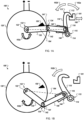
- FIGs. 1A and 1B are schematic diagrams that show an example unclaimed system 100 for locking a thrust reverser actuation system (TRAS).
- the TRAS is not shown in its entirety; a receiver 101 (e.g., catch, latch) of a TRAS reverser door (not shown) is included for purposes of describing the operation of the system 100.
- the system 100 includes a latch hook 110 having a catch 112 at a first latch end 113, a first pivotal mount 114 at a second latch end 115 opposite the first latch end 113, and a second pivotal mount 116 at a midpoint of the latch hook 110.
- a rotary actuator 120 is configured to selectably rotate a rotor shaft 122 in a first rotary direction (e.g., counterclockwise in the current example), represented by the arrow 102a in FIG. 1A , and in a second rotary direction, represented by the arrow 102b in FIG. 1B , opposite the first rotary direction 102a (e.g., clockwise in the current example).
- the rotary actuator 120 can be an electric motor or a rotary electric solenoid.
- a rotor arm 130 is coupled to the rotor shaft 122 at a first arm end 132 and extends radially outward from the rotor shaft 122 to a second arm end 134 opposite the first arm end 132.
- a link arm 140 (e.g., an idler link) is pivotably connected to the second arm end 134 by a third pivotal mount 141 at a first link end 142, and is pivotably connected to the second pivotal mount 116 at a second link end 144 opposite the first link end 142.
- the system 100 also includes a stop 150 (e.g., an over-center stop).
- the stop 150 is configured to prevent rotation of the rotor arm 130 and the rotor shaft 122 past a first rotary position in the first rotary direction 102a.
- the rotor arm 130 is rotated counterclockwise by the rotor shaft 122 to contact the stop 150 at a rotary position that is slightly less than 90 degrees (e.g., a bit less than the three o'clock position) from top dead center (e.g., the twelve o'clock position).
- the catch 112 is engaged with the receiver 101.
- the receiver 101 is confined to move linearly, substantially perpendicular to the latch hook 110, as illustrated by arrows 160.
- the rotor arm 130 and the link arm 140 form a linkage in which pivotal movement of the latch hook 110 can urge rotation of the rotary actuator 120.
- clockwise motion of the latch arm 110 will create tension along the rotor arm 130 and urge rotation of the rotary actuator 120 such that the third pivotal mount 141 is drawn into substantially direct alignment between the rotor shaft 122 and the second pivotal mount 116, as represented by line 164.
- Such a configuration is substantially stable in tension, but is mechanically unstable in compression.
- Counterclockwise motion of the latch arm 110 will compress the rotor arm 130, cause the rotor arm 130 to pivot relative to the link arm 140 about the third pivotal mount 141, and in turn urge rotation of the rotary actuator 120.
- the direction of rotation of the rotary actuator 120 is generally determined by the rotational side (e.g., clockwise or counterclockwise) of the line 164 the third pivotal mount 141 is already on.
- the third pivotal mount 141 is positioned counterclockwise relative to the line 164, then compression of the rotor arm 130 will generally urge further counterclockwise rotation of the rotary actuator 120.
- the third pivotal mount 141 is positioned clockwise relative to the line 164, then compression of the rotor arm 130 will generally urge further clockwise rotation of the rotary actuator 120.
- the stop 150 Stability of the system 100 in compression is provided by the stop 150.
- the stop 150, the rotor shaft 122, the rotor arm 130, the third pivotal mount 141, and the link arm 140 form an over center linkage that prevents back-driving of the system 100.
- the rotor shaft 122 is rotated such that the rotor arm 130 is rotated past direct alignment with the line 164, such that the third pivotal mount 141 is not positioned along the line 164.
- the third pivotal mount 141 and the rotor arm 130 are positioned counterclockwise relative to the line 164.
- counterclockwise motion of the latch hook 110 e.g., caused by leftward, back-driving movement of the receiver toward the system 100
- Counterclockwise rotation of the rotor arm 130 is limited by the stop 150.
- the stop 150 resists further counterclockwise rotation of the rotor arm 130, and by resisting such further rotation the stop 150 resists the counterclockwise motion of the latch arm 110 caused by the leftward, back-driving movement of the receiver 101. With the back-driving forces being resisted, the catch 122 is kept in engagement with the receiver 101.
- the system 100 is shown in a disengaged configuration.
- the rotary actuator 120 is actuated to rotate the rotor arm 130 clockwise, away from the stop 150, past the line 164.
- Such rotary motion urges counterclockwise motion 162b of the latch hook 110, causing the catch 112 to disengage from the receiver 101.
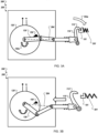
- FIGs. 2A and 2B are schematic diagrams that show an example of claimed system 200 for locking a TRAS.
- the system 200 is substantially similar to the system 100, with the addition of a protective housing 201 (e.g., a de-icing boot) configured to protect various moving components of the system 200 (e.g., parts that could become jammed or short-circuited by debris, such as ice or de-icing agents).
- a protective housing 201 e.g., a de-icing boot
- various moving components of the system 200 e.g., parts that could become jammed or short-circuited by debris, such as ice or de-icing agents.
- the TRAS is not shown in its entirety; the receiver 101 (e.g., a catch or latch) of a TRAS reverser door (not shown) is included for purposes of describing the operation of the system 200.
- the system 200 includes the latch hook 110.
- the rotary actuator 120 is configured to selectably rotate the rotor shaft 122 in the first rotary direction (e.g., counterclockwise in the current example), represented by the arrow 102a in FIG. 2A , and in the second rotary direction, represented by the arrow 102b in FIG. 2B , opposite the first rotary direction 102a (e.g., clockwise in the current example).
- the rotor arm 130 is coupled to the rotor shaft 122 at a first arm end 132 and extends radially outward from the rotor shaft 122 to the second arm end 134.
- a first link arm 240 e.g., an idler link
- the second link arm 250 extends from the fourth pivotal mount 251 at a third link end 252 to a fourth link end 254 opposite the third link end 252.
- the second link arm 250 is pivotably connected to the latch hook 110 by the second pivotal mount 116.
- the second link arm 250 is configured to extend through and retract from the protective housing 201. Motion of the second link arm 250 is directed by a guide 202 (e.g., to constrain the section link arm 250 to move reciprocally along a linear, axial path of motion). Referring now to FIG. 2B , the motion of the second link arm 250 is substantially linear, represented by the arrow 261. In some embodiments, a seal or compliant boot may be included between the protective housing 201 and the second link arm 250 to permit movement of the second link arm 250 relative to the protective housing 201 while also resisting intrusion of outside debris and contaminants into the protective housing 201.
- the system 200 also includes the stop 150.
- the stop 150 is configured to prevent rotation of the rotor arm 130 and the rotor shaft 122 past a first rotary position in the first rotary direction 102a.
- the rotor arm 130 is rotated counterclockwise by the rotor shaft 122 to contact the stop 150 at a rotary position that is slightly less than 90 degrees (e.g., a bit less than the three o'clock position) from top dead center (e.g., the twelve o'clock position).
- the catch 112 is engaged with the receiver 101.
- the receiver 101 is confined to move linearly, substantially perpendicular to the latch hook 110, as illustrated by arrows 160.
- the rotor arm 130, the first link arm 240, and the second link arm 250 form a linkage in which pivotal movement of the latch hook 110 can urge rotation of the rotary actuator 120.
- clockwise motion of the latch arm 110 will create tension along the rotor arm 130 and urge rotation of the rotary actuator 120 such that the third pivotal mount 241 is drawn into substantially direct alignment between the rotor shaft 122 and the fourth pivotal mount 251, as represented by line 264.
- Such a configuration is substantially stable in tension, but is mechanically unstable in compression.
- the direction of rotation of the rotary actuator 120 is generally determined by what rotational side (e.g., clockwise or counterclockwise) of the line 264 the third pivotal mount 241 is already on. For example, if the third pivotal mount 241 is positioned counterclockwise relative to the line 264, then compression of the rotor arm 130 will generally urge further counterclockwise rotation of the rotary actuator 120. In another example if the third pivotal mount 241 is positioned clockwise relative to the line 264, then compression of the rotor arm 130 will generally urge further clockwise rotation of the rotary actuator 120.
- rotational side e.g., clockwise or counterclockwise
- the stop 150 Stability of the system 200 in compression is provided by the stop 150.
- the stop 150, the rotor shaft 122, the rotor arm 130, the third pivotal mount 241, the link arm 140, the second link arm 250, and the fourth pivotal mount 251 form an over center linkage that prevents back-driving of the system 200.
- the rotor shaft 122 is rotated such that the rotor arm 130 is rotated past direct alignment with the line 264, such that the third pivotal mount 241 is not positioned along the line 264.
- the third pivotal mount 241 and the rotor arm 130 are positioned counterclockwise relative to the line 264.
- counterclockwise motion of the latch hook 110 e.g., caused by leftward, back-driving movement of the receiver toward from the system 200
- Counterclockwise rotation of the rotor arm 130 is limited by the stop 150.
- the stop 150 resists further counterclockwise rotation of the rotor arm 130, and by resisting such further rotation the stop 150 resists the counterclockwise motion of the latch arm 110 caused by the leftward, back-driving movement of the receiver 101. With the back-driving forces being resisted, the catch 112 is kept in engagement with the receiver 101.
- the system 200 is shown in a disengaged configuration.
- the rotary actuator 120 is actuated to rotate the rotor arm 130 clockwise, away from the stop 150, past the line 264.
- Such rotary motion urges counterclockwise motion 162b of the latch hook 110, causing the catch 112 to disengage from the receiver 101.
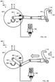
- FIGs. 3A and 3B are schematic diagrams that show an example of another claimed system 300 for locking a TRAS.
- the system 300 is the system 200 of FIGs. 2A and 2B , with the addition of a compliant member 301 (e.g., a spring) between the receiver 101 and a component to be latched, such as a TRAS reverser door (not shown).
- a compliant member 301 e.g., a spring
- the compliant member 301 can be added to the system 100 of FIGs. 1A and 1B as well.
- FIG. 3B the system 300 is shown in an unlatched configuration in which the catch 112 of the latch arm 110 is disengaged from the receiver 101.
- FIG. 3A the system 300 is shown in a latched configuration in which the catch 112 of the latch arm 110 is engaged with the receiver 101.
- the rotary actuator 120 rotates the rotor arm 130 counterclockwise to urge the catch 112 toward, and eventually into contact with the receiver 101.
- the catch 112 is urged into compression with the receiver 101, compressing the compliant member 310.
- expansion of the compliant member 301 back-drives the system 300 to urge the rotor arm 130 away from the line 264 in the direction 102a and into contact with the stop 150.
- the rotary actuator 120 may be kept energized in order to maintain the rotor arm in a position between the line 164 and the stop 150, such that any back-driving of the linkage will be resisted by contact between the rotor arm 130 and the stop 150.
- the rotor arm 130 is continually urged past the line 264 and into contact with the stop 150 by the back-driving force provided by the compliant member 301.
- the catch 112 will remain engaged with the receiver 101 even if latching (e.g., counterclockwise rotational) power is removed from the rotary actuator 120 intentionally (e.g., to conserve power) or unintentionally (e.g., a power outage).
- latching e.g., counterclockwise rotational
- unintentionally e.g., a power outage
- FIGs. 4A and 4B are schematic diagrams that show an example of another claimed system 400 for locking a TRAS.
- the system 400 is the system 200 of FIGs. 2A and 2B , with the addition of a second stop 450.
- the stop 450 can be added to the system 100 of FIGs. 1A and 1B as well.
- the stop 150 limits rotation of the rotor arm 130, by the rotary actuator 120, in the counterclockwise direction 102a.
- the stop 450 is also present in the rotational path of the rotor arm 130.
- the stop 450 is spaced apart from the stop 150 far enough to provide space for the rotor arm 130 (or some portion thereof) to be rotationally constrained between the stop 150 in the counterclockwise direction 102a and the stop 450 in the clockwise direction 102b when the rotor arm 130 is in the over-center, latched configuration shown in FIG. 4A .
- the stop 450 is moveable to selectively block (baulk) or permit (unbaulk) movement of the rotor arm 130, in the clockwise direction 102b, away from the latched configuration.
- An actuator 452 is controllable to actuate the movement of the stop 450.
- the stop 450 can be mounted on a piston that is configured to extend and retract the stop 450 into and out of the path of rotation of the rotor arm 130 (e.g., into an out of the plane of the views shown in FIGs. 4A and 4B ), and the actuator 452 can provide fluid (e.g., hydraulic, pneumatic) to drive the motion of the piston.
- the stop 450 can be mounted on a solenoid (e.g., a baulking solenoid) or other linear or rotary actuator that is configured to move the stop 450 into and out of the path of rotation of the rotor arm 130, and the actuator 452 can provide electrical power (e.g., a switch, a motor driver) to drive the motion of the stop 450.
- a solenoid e.g., a baulking solenoid
- electrical power e.g., a switch, a motor driver
- the rotor arm 130 is in the over-center, latched configuration.
- Rotation of the rotor arm 130 is constrained in the counterclockwise direction 102a by the stop 150, providing resistance against back-driving of the system 400 through the latch arm 110.
- Rotation of the rotor arm 130 is constrained in the clockwise direction 102b by the stop 450, preventing the rotor arm 130 from moving out of the over-center, latched configuration.
- the catch 112 will remain engaged with the receiver 101 even if latching (e.g., counterclockwise rotational) power is removed from the rotary actuator 120 intentionally (e.g., to conserve power) or unintentionally (e.g., a power outage).
- the actuator 452 can actuated the stop 450 such that the stop 450 is moved (as represented by the dotted lines in FIG. 4B ) out of the path of rotation of the rotor arm 130.
- the rotary actuator 120 can be actuated to rotate the rotor arm 130 in the clockwise direction 102b, out of the latched configuration and disengage the catch 112 from contact with the receiver 101.
- a stop can be configured to interfere with rotation of the rotary actuator (e.g., a clutch, a stop pin, escapement).
- FIGs. 5A and 5B are schematic diagrams that show an example of another claimed system 500 for locking a TRAS.
- the system 500 is the system 200 of FIGs. 2A and 2B , with the addition of a second stop 550.
- the stop 550 can be added to the system 100 of FIGs. 1A and 1B as well.
- the stop 550 is engageable to selectively block (baulk) or permit (unbaulk) linear movement of the second link arm 250 away from the latched configuration, as shown in FIG. 5A .
- An actuator 552 is controllable to actuate the movement of the stop 550.
- the stop 550 can be mounted on a piston that is configured to extend and retract the stop 550 into and out of the path of motion of the second link arm 250, and the actuator 552 can provide fluid (e.g., hydraulic, pneumatic) to drive the motion of the piston.
- the stop 550 can be mounted on a solenoid (e.g., a baulking solenoid) or other linear or rotary actuator that is configured to move the stop 550 into and out of the path of motion of the second link arm 250, and the actuator 552 can provide electrical power (e.g., a switch, a motor driver) to drive the motion of the stop 550.
- a solenoid e.g., a baulking solenoid
- electrical power e.g., a switch, a motor driver
- the stop 550 is extended so as to interfere with rightward (as illustrated) movement of a stop member 554 affixed to the second link arm 250.
- the extended configuration the back-driving forces applied to the latch hook 110 by the receiver 101 are resisted, and the rotor arm 130 is held in the latched, over-center position illustrated by FIG. 5A . With the back-driving forces being resisted, the catch 112 is kept in engagement with the receiver 101.
- the actuator 552 can actuated the stop 550 such that the stop 550 is moved out of the path of the stop member 554. As such, the catch 112 can be disengaged from contact with the receiver 101.
- FIGs. 6A and 6B are schematic diagrams that show an example of another claimed system 600 for locking a TRAS.
- the system 600 is a re-arrangement of the system 200 of FIGs. 2A and 2B , such that the axes of the rotor shaft 122 and the first pivotal mount 116 are close or share a common axis.
- the system 600 can be a more compact version of the system 200.
- the system 600 includes the latch hook 110.
- a rotary actuator 620 is configured to selectably rotate a rotor shaft 622 in the first rotary direction (e.g., counterclockwise in the current example), represented by the arrow 602a in FIG. 6A , and in the second rotary direction, represented by the arrow 602b in FIG. 6B , opposite the first rotary direction 602a (e.g., clockwise in the current example).
- a rotor arm 630 is coupled to the rotor shaft 622 at a first arm end 632 and extends radially outward from the rotor shaft 622 to the second arm end 634.
- a first link arm 640 (e.g., idler link) is pivotably connected to the second arm end 634 by a third pivotal mount 641 at a first link end 642, and is pivotably connected to a second link arm 650 by a fourth pivotal mount 651 at a second link end 644 opposite the first link end 642.
- the second link arm 650 extends from the fourth pivotal mount 651 at a third link end 652 to a fourth link end 654 opposite the third link end 652.
- the second link arm 650 is pivotably connected to the latch hook 110 by the second pivotal mount 116.
- the motion of the second link arm 650 is substantially linear, represented by the arrow 661 in FIG. 6B .
- the system 600 also includes a stop 650.
- the stop 650 is configured to prevent rotation of the rotor arm 630 and the rotor shaft 622 past a first rotary position in the first rotary direction 602a.
- the rotor arm 630 is rotated counterclockwise by the rotor shaft 622 to contact the stop 650 at a rotary position that is slightly greater than 90 degrees (e.g., a bit less than the nine o'clock position) from top dead center (e.g., the twelve o'clock position).
- the catch 112 is engaged with the receiver 101.
- the receiver 101 is confined to move linearly, substantially perpendicular to the latch hook 110, as illustrated by arrows 660.
- the rotor arm 630, the first link arm 640, and the second link arm 650 form a linkage in which pivotal movement of the latch hook 110 can urge rotation of the rotary actuator 620.
- Counterclockwise motion of the latch arm 110 will compress the second link arm 650, tension the first link arm 640, tension the rotor arm 630, cause the rotor arm 630 to pivot relative to the first link arm 640 about the third pivotal mount 641, and in turn urge rotation of the rotary actuator 620.
- Stability of the system 600 is provided in part by the stop 650.
- the stop 650, the rotor shaft 622, the rotor arm 630, the third pivotal mount 641, the link arm 640, the second link arm 650, and the fourth pivotal mount 651 form an over center linkage that prevents back-driving of the system 600.
- the rotor shaft 622 is rotated such that the rotor arm 630 is rotated past direct alignment between the rotor shaft 622 and the fourth pivotal mount 651, as represented by line 264, such that the third pivotal mount 641 is not positioned along the line 664.
- the third pivotal mount 641 and the rotor arm 630 are positioned counterclockwise relative to the line 664.
- counterclockwise motion of the latch hook 110 e.g., caused by leftward, back-driving movement of the receiver toward from the system 200
- Counterclockwise rotation of the rotor arm 630 is limited by the stop 650.
- the stop 650 resists further counterclockwise rotation of the rotor arm 630, and by resisting such further rotation the stop 650 resists the counterclockwise motion of the latch arm 110 caused by the leftward, back-driving movement of the receiver 101. With the back-driving forces being resisted, the catch 112 is kept in engagement with the receiver 101.
- the system 600 is shown in a disengaged configuration.
- the rotary actuator 620 is actuated to rotate the rotor arm 630 clockwise, away from the stop 650, closer to the line 664.
- Such rotary motion urges counterclockwise motion 662b of the latch hook 110, causing the catch 112 to disengage from the receiver 101.
- FIG. 7 is flow chart that shows an example of a process 700 for locking a TRAS.
- the process 700 can be performed using the example systems 100, 200, 300, 400, 500, and/or 600 of FIGs. 1A-6B .
- a lock apparatus includes a latch hook having a catch at a first latch end, a first pivotal mount at a second latch end opposite the first latch end, and a second pivotal mount, a rotary actuator configured to selectably rotate a rotor shaft in a first rotary direction and in a second rotary direction opposite the first rotary direction, a rotor arm coupled to the rotor shaft at a first arm end and extending radially outward from the rotor shaft to a second arm end opposite the first arm end, and a link arm pivotably connected to the second arm end at a first link end, and pivotably connected to the second pivotal mount at a second link end opposite the first link end.
- the example system 100 can be provided.
- the lock apparatus can also include a second link arm pivotally connected to the rotor arm at the second shaft end and pivotally connected to the link arm at the first link end, and the process 700 can also include constraining, by a guide, angular movement of the link arm, and moving the link arm linearly through the guide.
- the system 200 includes the second link arm 250 and the guide 202, and the second link arm 250 can be moved linearly through the guide 202.
- the rotary actuator is rotated in a first direction to a first rotary position.
- the rotary actuator 120 can be rotated in the direction 102a from the configuration shown in FIG. 1B to the configuration shown in FIG. 1A .
- the catch is engaged with a receiver during the rotating.
- the rotary actuator 120 is rotated in the direction 102a from the configuration shown in FIG. 1B , in which the catch 112 is disengaged from the receiver 101, to the configuration shown in FIG. 1A , the catch 112 is moved into engaging contact with the receiver 101.
- the process 700 can include contacting a stop at the first rotary position, and stopping, by the stop, rotation of the rotary actuator in the first rotary direction at the first rotary position.
- the rotor arm 130 can rotated into contact with the stop 150 by the rotary actuator 120.
- rotation of the rotary actuator 120 in the direction 102a is stopped.
- the process 700 can include applying a back force to the catch while rotary actuator is proximal the first rotary position, urging rotation of the rotary actuator in the first rotary direction, resisting, by the stop, the back force, and maintaining engagement of the catch and the receiver.
- the receiver 101 can back-load the system 100 (e.g., by moving leftward in the view shown in FIG. 1A ).
- Such back-loading can urge counterclockwise rotation (e.g., in direction 102a) of the rotor arm 130 and the rotary actuator 120.
- Such rotation can cause the rotor arm 130 to contact the stop 150, and the stop 150 can resist further rotation in the direction 102a and keep the catch 112 in latching contact with the receiver 101 (e.g., through the linkage of the rotor arm 130, the link arm 140, and the latch hook 110).
- a bias member can urge the rotary actuator in the first rotary direction.
- the rotary actuator is rotated in a second direction opposite the first direction to a second rotary position.
- the rotary actuator 120 can be rotated in the direction 102b from the configuration shown in FIG. 1A to the configuration shown in FIG. 1B .
- the catch is disengaged from the receiver.
- the rotary actuator 120 is rotated in the direction 102b from the configuration shown in FIG. 1A , in which the catch 112 is engaged in contact with the receiver 101, to the configuration shown in FIG. 1B , the catch 112 is moved out of engaging contact with the receiver 101.
- the process 700 can include configuring a moveable stop in a first configuration, urging rotation of the rotary actuator in the second rotary direction, contacting the moveable stop at a second rotary position, stopping, by the moveable stop in the first configuration, rotation of the rotary actuator in the second rotary direction at the second rotary position, configuring the moveable stop in a second configuration, urging rotation of the rotary actuator in the second rotary direction, and rotating the rotary actuator in the second rotary direction past the second position.
- the system 400 includes the stop 450.
- the stop 450 can controlled (e.g., actuated) to prevent and permit movement of the rotor arm 130 away from the latched position shown in FIG. 4A .
- the rotor arm 130 With the rotary actuator 120 and the rotor arm 130 in the latched configuration and the stop 450 engaged, the rotor arm 130 is substantially maintained in the latched position. If the rotary actuator 120 is rotated in the clockwise direction 102b, then the motion will be resisted by the contact between the rotor arm 130 and the stop 450, and the system 400 will be held in the latched configuration. If the stop 450 is disengaged and the rotary actuator 120 is rotated in the clockwise direction 102b, then the stop 450 will not interfere with the motion of the rotor arm 130 as it moves toward the unlatched configuration shown in FIG. 4B .
- the process 700 can include configuring a moveable stop in a first configuration, urging movement of the link arm, stopping, by the moveable stop in the first configuration, movement of the link arm, configuring the moveable stop in a second configuration, urging movement of the link arm, and permitting, by the moveable stop in the second configuration, movement of the link arm.
- the system 500 includes the stop 550.
- the stop 550 can controlled (e.g., actuated) to prevent and permit movement of the second link arm 250 away from the latched position shown in FIG. 5A . With the rotary actuator 120 and the second link arm 250 in the latched configuration and the stop 550 engaged, the second link arm 250 is substantially maintained in the latched position.
- the rotary actuator 120 If the rotary actuator 120 is rotated in the clockwise direction 102b, then the motion will be resisted by the contact between the second link arm 250 and the stop member 554, and the system 500 will be held in the latched configuration. If the stop 550 is disengaged and the rotary actuator 120 is rotated in the clockwise direction 102b, then the stop 550 will not interfere with the stop member 554 and motion of the second link arm 250 as they move toward the unlatched configuration shown in FIG. 5B .
Landscapes
- Engineering & Computer Science (AREA)
- Mechanical Engineering (AREA)
- Chemical & Material Sciences (AREA)
- Combustion & Propulsion (AREA)
- General Engineering & Computer Science (AREA)
- Lock And Its Accessories (AREA)
- Transmission Devices (AREA)
- Automotive Seat Belt Assembly (AREA)
Description
- This patent claims priority to
U.S. Patent Application No. 15/409,240 filed on January 18, 2017 - This patent relates to lock mechanisms for thrust reverser actuation systems.
- Thrust Reverser Actuation Systems (TRAS) power and control the deployment of aircraft thrust reversers. Thrust reversal, also called reverse thrust, involves the temporary diversion of a jet aircraft's exhaust so that it acts against the forward travel of the aircraft, providing deceleration, for example, to help slow an aircraft after touch-down. Such devices are considered important for safe operations by airlines.
- However, such devices can also negatively affect the operation of an aircraft if they are misused or malfunction. A number of aircraft accidents have been traced back to accidental TRAS deployments. As such, many TRAS designs include locking mechanisms to ensure that the TRAS remains stowed until needed. Many of these systems utilize large bias springs to bias locks toward the locked position and to overcome vibration and air load forces, and use hydraulic linear actuators with high power densities to overcome the bias springs in order to release the lock. Such systems add weight and consume space, both of which can be limited, especially in aircraft applications.
-
US 2003/0146643 describes an interlocking device for the folding roof of a motor vehicle with a locking hook which is pivotally mounted on the front frame part of the folding roof and which can be moved by means of a multiple connecting rod mechanism and can be interlocked in latching engagement on a vehicle-mounted abutment, the multiple connecting rod mechanism, especially a four-bar mechanism, containing the locking hook and being located self-locking in the closed position. -
US 2016/0201364 describes an actuating system for an actuatable door that comprises at least one latching device with a latching hook that is adapted for locking the actuatable door in a closed position, the latching hook being pivotally mounted to an associated pivot bearing and connected to a pivotable mechanical transmission element via a coupling link, which is pivotally mounted to the latching hook and to the pivotable mechanical transmission element, the pivotable mechanical transmission element being coupled to a rotatable latching shaft, wherein rotation of the rotatable latching shaft in operation results in pivoting of the pivotable mechanical transmission element and pivoting of the latching hook around the associated pivot bearing, wherein the pivotable mechanical transmission element is mounted onto the rotatable latching shaft. - In general, this patent describes lock mechanisms for thrust reverser actuation systems.
- The invention is defined in the claims.
- The systems and techniques described here may provide one or more of the following advantages. First, a system can provide a robust locking action. Second, the system can be implemented with actuators having reduced space and weight requirements. Third, the system can be driven electrically rather than hydraulically or pneumatically. Fourth, the system can be implemented without the additional use of gearboxes or stroke amplifiers.
- The details of one or more implementations are set forth in the accompanying drawings and the description below. Other features and advantages will be apparent from the description and drawings, and from the claims.
-
-
FIGs. 1A and 1B are schematic diagrams that show an unclaimed example of a system for locking a thrust reverser actuation system (TRAS). -
FIGs. 2A and 2B are schematic diagrams that show another, claimed example of a system for locking a TRAS. -
FIGs. 3A and 3B are schematic diagrams that show another, claimed example of a system for locking a TRAS. -
FIGs. 4A and 4B are schematic diagrams that show another, claimed example of a system for locking a TRAS. -
FIGs. 5A and 5B are schematic diagrams that show another, claimed example of a system for locking a TRAS. -
FIGs. 6A and 6B are schematic diagrams that show another, claimed example of a system for locking a TRAS. -
FIG. 7 is flow chart that shows an example of a process for locking a TRAS. - This document describes systems and techniques for locking a thrust reverser actuation system (TRAS). Many TRAS systems include locking mechanisms to keep jet engine reverser cowl sections from deploying accidentally. Some existing TRAS locking mechanisms systems utilize large bias springs to bias locks toward the locked position and to overcome vibration and air load forces, and use hydraulic linear actuators with high power densities to overcome the bias springs in order to release the locks. Such systems add weight and consume space, both of which can be limited especially in aircraft applications.
- Electric actuation generally has a lower power density and range of motion when compared to hydraulic actuation, which limits the use of electric systems as replacements for hydraulics. For example, electric motor-driven locks sometimes require the use of gearing, control systems, limit switches, and other components in order to replicate the power and range of a hydraulic system, but such components add weight, add cost, and consume space. In other examples, electric linear solenoids can be used, but solenoids generally have strokes that are too short (e.g., 2 to 25 mm (80 to 100 thousands of an inch)) to use as a replacement for hydraulics without stroke amplification. However, mechanisms for stroke amplification also consume space, add cost and weight, and also generally trade solenoid force in exchange for stroke length thereby reducing overall robustness of the system.
- Generally speaking, the systems and techniques described in this document use rotary electric actuation, rather than linear hydraulic or pneumatic actuation, to lock a TRAS. The rotary actuators are used to actuate over-center mechanisms to lock and unlock the TRAS, rather than lock and unlock the TRAS directly. The over-center mechanisms can provide the desired robustness needed to keep a TRAS secured, and actuation of the over-center mechanisms can be performed with a relatively low amount of mechanical power (e.g., when compared to the amount of power needed to secure a TRAS lock directly).
-
FIGs. 1A and 1B are schematic diagrams that show an exampleunclaimed system 100 for locking a thrust reverser actuation system (TRAS). In the illustrated example, the TRAS is not shown in its entirety; a receiver 101 (e.g., catch, latch) of a TRAS reverser door (not shown) is included for purposes of describing the operation of thesystem 100. - The
system 100 includes alatch hook 110 having acatch 112 at afirst latch end 113, a firstpivotal mount 114 at asecond latch end 115 opposite thefirst latch end 113, and a secondpivotal mount 116 at a midpoint of thelatch hook 110. Arotary actuator 120 is configured to selectably rotate arotor shaft 122 in a first rotary direction (e.g., counterclockwise in the current example), represented by thearrow 102a inFIG. 1A , and in a second rotary direction, represented by thearrow 102b inFIG. 1B , opposite the firstrotary direction 102a (e.g., clockwise in the current example). Therotary actuator 120 can be an electric motor or a rotary electric solenoid. - A
rotor arm 130 is coupled to therotor shaft 122 at afirst arm end 132 and extends radially outward from therotor shaft 122 to asecond arm end 134 opposite thefirst arm end 132. A link arm 140 (e.g., an idler link) is pivotably connected to thesecond arm end 134 by a thirdpivotal mount 141 at afirst link end 142, and is pivotably connected to the secondpivotal mount 116 at asecond link end 144 opposite thefirst link end 142. - The
system 100 also includes a stop 150 (e.g., an over-center stop). Thestop 150 is configured to prevent rotation of therotor arm 130 and therotor shaft 122 past a first rotary position in the firstrotary direction 102a. For example, inFIG. 1A , therotor arm 130 is rotated counterclockwise by therotor shaft 122 to contact thestop 150 at a rotary position that is slightly less than 90 degrees (e.g., a bit less than the three o'clock position) from top dead center (e.g., the twelve o'clock position). - Referring to
FIG. 1A , thecatch 112 is engaged with thereceiver 101. Thereceiver 101 is confined to move linearly, substantially perpendicular to thelatch hook 110, as illustrated byarrows 160. Therotor arm 130 and thelink arm 140 form a linkage in which pivotal movement of thelatch hook 110 can urge rotation of therotary actuator 120. In general, clockwise motion of thelatch arm 110 will create tension along therotor arm 130 and urge rotation of therotary actuator 120 such that the thirdpivotal mount 141 is drawn into substantially direct alignment between therotor shaft 122 and the secondpivotal mount 116, as represented byline 164. Such a configuration is substantially stable in tension, but is mechanically unstable in compression. Counterclockwise motion of thelatch arm 110 will compress therotor arm 130, cause therotor arm 130 to pivot relative to thelink arm 140 about the thirdpivotal mount 141, and in turn urge rotation of therotary actuator 120. - The direction of rotation of the
rotary actuator 120 is generally determined by the rotational side (e.g., clockwise or counterclockwise) of theline 164 the thirdpivotal mount 141 is already on. For example, if the thirdpivotal mount 141 is positioned counterclockwise relative to theline 164, then compression of therotor arm 130 will generally urge further counterclockwise rotation of therotary actuator 120. In another example if the thirdpivotal mount 141 is positioned clockwise relative to theline 164, then compression of therotor arm 130 will generally urge further clockwise rotation of therotary actuator 120. - Stability of the
system 100 in compression is provided by thestop 150. Thestop 150, therotor shaft 122, therotor arm 130, the thirdpivotal mount 141, and thelink arm 140 form an over center linkage that prevents back-driving of thesystem 100. - In the illustrated example, the
rotor shaft 122 is rotated such that therotor arm 130 is rotated past direct alignment with theline 164, such that the thirdpivotal mount 141 is not positioned along theline 164. The thirdpivotal mount 141 and therotor arm 130 are positioned counterclockwise relative to theline 164. As such, counterclockwise motion of the latch hook 110 (e.g., caused by leftward, back-driving movement of the receiver toward the system 100) can urge counterclockwise rotation of therotary actuator 120. Counterclockwise rotation of therotor arm 130 is limited by thestop 150. As such, thestop 150 resists further counterclockwise rotation of therotor arm 130, and by resisting such further rotation thestop 150 resists the counterclockwise motion of thelatch arm 110 caused by the leftward, back-driving movement of thereceiver 101. With the back-driving forces being resisted, thecatch 122 is kept in engagement with thereceiver 101. - In the illustrated configuration, movement of the
receiver 101 away from the system 100 (e.g., to the right) urges contact between thecatch 112 and thereceiver 101, which in turn urges clockwise pivotal motion, represented byarrow 162a, of thelatch hook 110. Such pivotal motion draws thecatch 112 into more forceful engagement with thereceiver 101, resisting disengagement of thereceiver 101 from thesystem 100. - Referring now to
FIG. 1B , thesystem 100 is shown in a disengaged configuration. In the illustrated example, therotary actuator 120 is actuated to rotate therotor arm 130 clockwise, away from thestop 150, past theline 164. Such rotary motion urgescounterclockwise motion 162b of thelatch hook 110, causing thecatch 112 to disengage from thereceiver 101. -
FIGs. 2A and 2B are schematic diagrams that show an example of claimedsystem 200 for locking a TRAS. In general, thesystem 200 is substantially similar to thesystem 100, with the addition of a protective housing 201 (e.g., a de-icing boot) configured to protect various moving components of the system 200 (e.g., parts that could become jammed or short-circuited by debris, such as ice or de-icing agents). In the illustrated example, the TRAS is not shown in its entirety; the receiver 101 (e.g., a catch or latch) of a TRAS reverser door (not shown) is included for purposes of describing the operation of thesystem 200. - The
system 200 includes thelatch hook 110. Therotary actuator 120 is configured to selectably rotate therotor shaft 122 in the first rotary direction (e.g., counterclockwise in the current example), represented by thearrow 102a inFIG. 2A , and in the second rotary direction, represented by thearrow 102b inFIG. 2B , opposite the firstrotary direction 102a (e.g., clockwise in the current example). - The
rotor arm 130 is coupled to therotor shaft 122 at afirst arm end 132 and extends radially outward from therotor shaft 122 to thesecond arm end 134. A first link arm 240 (e.g., an idler link) is pivotably connected to thesecond arm end 134 by a thirdpivotal mount 241 at afirst link end 242, and is pivotably connected to a second link arm 250 (e.g., a guided rod) by a fourthpivotal mount 251 at asecond link end 244 opposite thefirst link end 242. Thesecond link arm 250 extends from the fourthpivotal mount 251 at athird link end 252 to afourth link end 254 opposite thethird link end 252. Thesecond link arm 250 is pivotably connected to thelatch hook 110 by the secondpivotal mount 116. - The
second link arm 250 is configured to extend through and retract from theprotective housing 201. Motion of thesecond link arm 250 is directed by a guide 202 (e.g., to constrain thesection link arm 250 to move reciprocally along a linear, axial path of motion). Referring now toFIG. 2B , the motion of thesecond link arm 250 is substantially linear, represented by thearrow 261. In some embodiments, a seal or compliant boot may be included between theprotective housing 201 and thesecond link arm 250 to permit movement of thesecond link arm 250 relative to theprotective housing 201 while also resisting intrusion of outside debris and contaminants into theprotective housing 201. - Returning to
FIG. 2A , thesystem 200 also includes thestop 150. Thestop 150 is configured to prevent rotation of therotor arm 130 and therotor shaft 122 past a first rotary position in the firstrotary direction 102a. For example, inFIG. 2A , therotor arm 130 is rotated counterclockwise by therotor shaft 122 to contact thestop 150 at a rotary position that is slightly less than 90 degrees (e.g., a bit less than the three o'clock position) from top dead center (e.g., the twelve o'clock position). - Still referring to
FIG. 2A , thecatch 112 is engaged with thereceiver 101. Thereceiver 101 is confined to move linearly, substantially perpendicular to thelatch hook 110, as illustrated byarrows 160. Therotor arm 130, thefirst link arm 240, and thesecond link arm 250 form a linkage in which pivotal movement of thelatch hook 110 can urge rotation of therotary actuator 120. In general, clockwise motion of thelatch arm 110 will create tension along therotor arm 130 and urge rotation of therotary actuator 120 such that the thirdpivotal mount 241 is drawn into substantially direct alignment between therotor shaft 122 and the fourthpivotal mount 251, as represented byline 264. Such a configuration is substantially stable in tension, but is mechanically unstable in compression. Counterclockwise motion of thelatch arm 110 will compress thesecond link arm 250, compress thefirst link arm 240, compress therotor arm 130, cause therotor arm 130 to pivot relative to thefirst link arm 240 about the thirdpivotal mount 241, and in turn urge rotation of therotary actuator 120. - The direction of rotation of the
rotary actuator 120 is generally determined by what rotational side (e.g., clockwise or counterclockwise) of theline 264 the thirdpivotal mount 241 is already on. For example, if the thirdpivotal mount 241 is positioned counterclockwise relative to theline 264, then compression of therotor arm 130 will generally urge further counterclockwise rotation of therotary actuator 120. In another example if the thirdpivotal mount 241 is positioned clockwise relative to theline 264, then compression of therotor arm 130 will generally urge further clockwise rotation of therotary actuator 120. - Stability of the
system 200 in compression is provided by thestop 150. Thestop 150, therotor shaft 122, therotor arm 130, the thirdpivotal mount 241, thelink arm 140, thesecond link arm 250, and the fourthpivotal mount 251 form an over center linkage that prevents back-driving of thesystem 200. - In the illustrated example, the
rotor shaft 122 is rotated such that therotor arm 130 is rotated past direct alignment with theline 264, such that the thirdpivotal mount 241 is not positioned along theline 264. The thirdpivotal mount 241 and therotor arm 130 are positioned counterclockwise relative to theline 264. As such, counterclockwise motion of the latch hook 110 (e.g., caused by leftward, back-driving movement of the receiver toward from the system 200) can urge counterclockwise rotation of therotary actuator 120. Counterclockwise rotation of therotor arm 130 is limited by thestop 150. As such, thestop 150 resists further counterclockwise rotation of therotor arm 130, and by resisting such further rotation thestop 150 resists the counterclockwise motion of thelatch arm 110 caused by the leftward, back-driving movement of thereceiver 101. With the back-driving forces being resisted, thecatch 112 is kept in engagement with thereceiver 101. - In the illustrated configuration, movement of the
receiver 101 away from the system 200 (e.g., to the right) urges contact between thecatch 112 and thereceiver 101, which in turn urges clockwise pivotal motion, represented byarrow 162a, of thelatch hook 110. Such pivotal motion draws thecatch 112 into more forceful engagement with thereceiver 101, resisting disengagement of thereceiver 101 from thesystem 200. - Referring now to
FIG. 2B , thesystem 200 is shown in a disengaged configuration. In the illustrated example, therotary actuator 120 is actuated to rotate therotor arm 130 clockwise, away from thestop 150, past theline 264. Such rotary motion urgescounterclockwise motion 162b of thelatch hook 110, causing thecatch 112 to disengage from thereceiver 101. -
FIGs. 3A and 3B are schematic diagrams that show an example of another claimedsystem 300 for locking a TRAS. In general, thesystem 300 is thesystem 200 ofFIGs. 2A and 2B , with the addition of a compliant member 301 (e.g., a spring) between thereceiver 101 and a component to be latched, such as a TRAS reverser door (not shown). In some embodiments, thecompliant member 301 can be added to thesystem 100 ofFIGs. 1A and 1B as well. - In
FIG. 3B , thesystem 300 is shown in an unlatched configuration in which thecatch 112 of thelatch arm 110 is disengaged from thereceiver 101. InFIG. 3A , thesystem 300 is shown in a latched configuration in which thecatch 112 of thelatch arm 110 is engaged with thereceiver 101. To drive thesystem 300 from the unlatched configuration shown inFIG. 3B to the latched configuration shown inFIG. 3A , therotary actuator 120 rotates therotor arm 130 counterclockwise to urge thecatch 112 toward, and eventually into contact with thereceiver 101. - As the
rotor arm 130 approaches alignment with theline 264 in thecounterclockwise direction 102a, thecatch 112 is urged into compression with thereceiver 101, compressing the compliant member 310. As therotor arm 130 is rotated over center, past theline 264, expansion of thecompliant member 301 back-drives thesystem 300 to urge therotor arm 130 away from theline 264 in thedirection 102a and into contact with thestop 150. - The addition of the
compliant member 301 provides additional functionality to thesystem 200. In the example of thesystem 200, therotary actuator 120 may be kept energized in order to maintain the rotor arm in a position between theline 164 and thestop 150, such that any back-driving of the linkage will be resisted by contact between therotor arm 130 and thestop 150. In the example of thesystem 300, once latched (e.g., as depicted inFIG. 3A ) therotor arm 130 is continually urged past theline 264 and into contact with thestop 150 by the back-driving force provided by thecompliant member 301. In such examples, thecatch 112 will remain engaged with thereceiver 101 even if latching (e.g., counterclockwise rotational) power is removed from therotary actuator 120 intentionally (e.g., to conserve power) or unintentionally (e.g., a power outage). -
FIGs. 4A and 4B are schematic diagrams that show an example of another claimedsystem 400 for locking a TRAS. In general, thesystem 400 is thesystem 200 ofFIGs. 2A and 2B , with the addition of asecond stop 450. In some embodiments, thestop 450 can be added to thesystem 100 ofFIGs. 1A and 1B as well. - As in the
example systems FIGs. 1A-3B , thestop 150 limits rotation of therotor arm 130, by therotary actuator 120, in thecounterclockwise direction 102a. However, in the example of thesystem 400, thestop 450 is also present in the rotational path of therotor arm 130. Thestop 450 is spaced apart from thestop 150 far enough to provide space for the rotor arm 130 (or some portion thereof) to be rotationally constrained between thestop 150 in thecounterclockwise direction 102a and thestop 450 in theclockwise direction 102b when therotor arm 130 is in the over-center, latched configuration shown inFIG. 4A . - The
stop 450 is moveable to selectively block (baulk) or permit (unbaulk) movement of therotor arm 130, in theclockwise direction 102b, away from the latched configuration. Anactuator 452 is controllable to actuate the movement of thestop 450. For example, thestop 450 can be mounted on a piston that is configured to extend and retract thestop 450 into and out of the path of rotation of the rotor arm 130 (e.g., into an out of the plane of the views shown inFIGs. 4A and 4B ), and theactuator 452 can provide fluid (e.g., hydraulic, pneumatic) to drive the motion of the piston. In another example, thestop 450 can be mounted on a solenoid (e.g., a baulking solenoid) or other linear or rotary actuator that is configured to move thestop 450 into and out of the path of rotation of therotor arm 130, and theactuator 452 can provide electrical power (e.g., a switch, a motor driver) to drive the motion of thestop 450. - Referring now to
FIG. 4A , therotor arm 130 is in the over-center, latched configuration. Rotation of therotor arm 130 is constrained in thecounterclockwise direction 102a by thestop 150, providing resistance against back-driving of thesystem 400 through thelatch arm 110. Rotation of therotor arm 130 is constrained in theclockwise direction 102b by thestop 450, preventing therotor arm 130 from moving out of the over-center, latched configuration. In such examples, thecatch 112 will remain engaged with thereceiver 101 even if latching (e.g., counterclockwise rotational) power is removed from therotary actuator 120 intentionally (e.g., to conserve power) or unintentionally (e.g., a power outage). - Referring now to
FIG. 4B , theactuator 452 can actuated thestop 450 such that thestop 450 is moved (as represented by the dotted lines inFIG. 4B ) out of the path of rotation of therotor arm 130. As such, therotary actuator 120 can be actuated to rotate therotor arm 130 in theclockwise direction 102b, out of the latched configuration and disengage thecatch 112 from contact with thereceiver 101. - In some embodiments, other forms of the
stop 450 can be implemented. For example, instead of mechanically interfering with the motion of therotor arm 130, a stop can be configured to interfere with rotation of the rotary actuator (e.g., a clutch, a stop pin, escapement). -
FIGs. 5A and 5B are schematic diagrams that show an example of another claimedsystem 500 for locking a TRAS. In general, thesystem 500 is thesystem 200 ofFIGs. 2A and 2B , with the addition of asecond stop 550. In some embodiments, thestop 550 can be added to thesystem 100 ofFIGs. 1A and 1B as well. - The
stop 550 is engageable to selectively block (baulk) or permit (unbaulk) linear movement of thesecond link arm 250 away from the latched configuration, as shown inFIG. 5A . Anactuator 552 is controllable to actuate the movement of thestop 550. For example, thestop 550 can be mounted on a piston that is configured to extend and retract thestop 550 into and out of the path of motion of thesecond link arm 250, and theactuator 552 can provide fluid (e.g., hydraulic, pneumatic) to drive the motion of the piston. In another example, thestop 550 can be mounted on a solenoid (e.g., a baulking solenoid) or other linear or rotary actuator that is configured to move thestop 550 into and out of the path of motion of thesecond link arm 250, and theactuator 552 can provide electrical power (e.g., a switch, a motor driver) to drive the motion of thestop 550. - In the illustrated example, the
stop 550 is extended so as to interfere with rightward (as illustrated) movement of astop member 554 affixed to thesecond link arm 250. In the extended configuration, the back-driving forces applied to thelatch hook 110 by thereceiver 101 are resisted, and therotor arm 130 is held in the latched, over-center position illustrated byFIG. 5A . With the back-driving forces being resisted, thecatch 112 is kept in engagement with thereceiver 101. - Referring now to
FIG. 5B , theactuator 552 can actuated thestop 550 such that thestop 550 is moved out of the path of thestop member 554. As such, thecatch 112 can be disengaged from contact with thereceiver 101. -
FIGs. 6A and 6B are schematic diagrams that show an example of another claimedsystem 600 for locking a TRAS. In general, thesystem 600 is a re-arrangement of thesystem 200 ofFIGs. 2A and 2B , such that the axes of therotor shaft 122 and the firstpivotal mount 116 are close or share a common axis. In some embodiments, thesystem 600 can be a more compact version of thesystem 200. - The
system 600 includes thelatch hook 110. Arotary actuator 620 is configured to selectably rotate arotor shaft 622 in the first rotary direction (e.g., counterclockwise in the current example), represented by thearrow 602a inFIG. 6A , and in the second rotary direction, represented by thearrow 602b inFIG. 6B , opposite the firstrotary direction 602a (e.g., clockwise in the current example). - A
rotor arm 630 is coupled to therotor shaft 622 at afirst arm end 632 and extends radially outward from therotor shaft 622 to thesecond arm end 634. A first link arm 640 (e.g., idler link) is pivotably connected to thesecond arm end 634 by a thirdpivotal mount 641 at afirst link end 642, and is pivotably connected to asecond link arm 650 by a fourthpivotal mount 651 at asecond link end 644 opposite thefirst link end 642. Thesecond link arm 650 extends from the fourthpivotal mount 651 at athird link end 652 to afourth link end 654 opposite thethird link end 652. Thesecond link arm 650 is pivotably connected to thelatch hook 110 by the secondpivotal mount 116. The motion of thesecond link arm 650 is substantially linear, represented by the arrow 661 inFIG. 6B . - Returning to
FIG. 6A , thesystem 600 also includes astop 650. Thestop 650 is configured to prevent rotation of therotor arm 630 and therotor shaft 622 past a first rotary position in the firstrotary direction 602a. For example, inFIG. 6A , therotor arm 630 is rotated counterclockwise by therotor shaft 622 to contact thestop 650 at a rotary position that is slightly greater than 90 degrees (e.g., a bit less than the nine o'clock position) from top dead center (e.g., the twelve o'clock position). - Still referring to
FIG. 6A , thecatch 112 is engaged with thereceiver 101. Thereceiver 101 is confined to move linearly, substantially perpendicular to thelatch hook 110, as illustrated byarrows 660. Therotor arm 630, thefirst link arm 640, and thesecond link arm 650 form a linkage in which pivotal movement of thelatch hook 110 can urge rotation of therotary actuator 620. Counterclockwise motion of thelatch arm 110 will compress thesecond link arm 650, tension thefirst link arm 640, tension therotor arm 630, cause therotor arm 630 to pivot relative to thefirst link arm 640 about the thirdpivotal mount 641, and in turn urge rotation of therotary actuator 620. - Stability of the
system 600 is provided in part by thestop 650. Thestop 650, therotor shaft 622, therotor arm 630, the thirdpivotal mount 641, thelink arm 640, thesecond link arm 650, and the fourthpivotal mount 651 form an over center linkage that prevents back-driving of thesystem 600. - In the illustrated example, the
rotor shaft 622 is rotated such that therotor arm 630 is rotated past direct alignment between therotor shaft 622 and the fourthpivotal mount 651, as represented byline 264, such that the thirdpivotal mount 641 is not positioned along theline 664. The thirdpivotal mount 641 and therotor arm 630 are positioned counterclockwise relative to theline 664. As such, counterclockwise motion of the latch hook 110 (e.g., caused by leftward, back-driving movement of the receiver toward from the system 200) can urge counterclockwise rotation of therotary actuator 620. Counterclockwise rotation of therotor arm 630 is limited by thestop 650. As such, thestop 650 resists further counterclockwise rotation of therotor arm 630, and by resisting such further rotation thestop 650 resists the counterclockwise motion of thelatch arm 110 caused by the leftward, back-driving movement of thereceiver 101. With the back-driving forces being resisted, thecatch 112 is kept in engagement with thereceiver 101. - In the illustrated configuration, movement of the
receiver 101 away from the system 600 (e.g., to the right) urges contact between thecatch 112 and thereceiver 101, which in turn urges clockwise pivotal motion, represented byarrow 662a, of thelatch hook 110. Such pivotal motion draws thecatch 112 into more forceful engagement with thereceiver 101, resisting disengagement of thereceiver 101 from thesystem 600. - Referring now to
FIG. 6B , thesystem 600 is shown in a disengaged configuration. In the illustrated example, therotary actuator 620 is actuated to rotate therotor arm 630 clockwise, away from thestop 650, closer to theline 664. Such rotary motion urgescounterclockwise motion 662b of thelatch hook 110, causing thecatch 112 to disengage from thereceiver 101. -
FIG. 7 is flow chart that shows an example of aprocess 700 for locking a TRAS. In some implementations, theprocess 700 can be performed using theexample systems FIGs. 1A-6B . - At 710, a lock apparatus is provided. The lock apparatus includes a latch hook having a catch at a first latch end, a first pivotal mount at a second latch end opposite the first latch end, and a second pivotal mount, a rotary actuator configured to selectably rotate a rotor shaft in a first rotary direction and in a second rotary direction opposite the first rotary direction, a rotor arm coupled to the rotor shaft at a first arm end and extending radially outward from the rotor shaft to a second arm end opposite the first arm end, and a link arm pivotably connected to the second arm end at a first link end, and pivotably connected to the second pivotal mount at a second link end opposite the first link end. For example, the
example system 100 can be provided. - In some implementations, the lock apparatus can also include a second link arm pivotally connected to the rotor arm at the second shaft end and pivotally connected to the link arm at the first link end, and the
process 700 can also include constraining, by a guide, angular movement of the link arm, and moving the link arm linearly through the guide. For example, thesystem 200 includes thesecond link arm 250 and theguide 202, and thesecond link arm 250 can be moved linearly through theguide 202. - At 720, the rotary actuator is rotated in a first direction to a first rotary position. For example, the
rotary actuator 120 can be rotated in thedirection 102a from the configuration shown inFIG. 1B to the configuration shown inFIG. 1A . - At 730 the catch is engaged with a receiver during the rotating. For example, as the
rotary actuator 120 is rotated in thedirection 102a from the configuration shown inFIG. 1B , in which thecatch 112 is disengaged from thereceiver 101, to the configuration shown inFIG. 1A , thecatch 112 is moved into engaging contact with thereceiver 101. - In some implementations, the
process 700 can include contacting a stop at the first rotary position, and stopping, by the stop, rotation of the rotary actuator in the first rotary direction at the first rotary position. For example, therotor arm 130 can rotated into contact with thestop 150 by therotary actuator 120. When therotor arm 130 contacts thestop 150, rotation of therotary actuator 120 in thedirection 102a is stopped. - In some implementations, the
process 700 can include applying a back force to the catch while rotary actuator is proximal the first rotary position, urging rotation of the rotary actuator in the first rotary direction, resisting, by the stop, the back force, and maintaining engagement of the catch and the receiver. For example, thereceiver 101 can back-load the system 100 (e.g., by moving leftward in the view shown inFIG. 1A ). Such back-loading can urge counterclockwise rotation (e.g., indirection 102a) of therotor arm 130 and therotary actuator 120. Such rotation can cause therotor arm 130 to contact thestop 150, and thestop 150 can resist further rotation in thedirection 102a and keep thecatch 112 in latching contact with the receiver 101 (e.g., through the linkage of therotor arm 130, thelink arm 140, and the latch hook 110). - A bias member can urge the rotary actuator in the first rotary direction.
- At 740, the rotary actuator is rotated in a second direction opposite the first direction to a second rotary position. For example, the
rotary actuator 120 can be rotated in thedirection 102b from the configuration shown inFIG. 1A to the configuration shown inFIG. 1B . - At 750, the catch is disengaged from the receiver. For example, as the
rotary actuator 120 is rotated in thedirection 102b from the configuration shown inFIG. 1A , in which thecatch 112 is engaged in contact with thereceiver 101, to the configuration shown inFIG. 1B , thecatch 112 is moved out of engaging contact with thereceiver 101. - In some implementations, the
process 700 can include configuring a moveable stop in a first configuration, urging rotation of the rotary actuator in the second rotary direction, contacting the moveable stop at a second rotary position, stopping, by the moveable stop in the first configuration, rotation of the rotary actuator in the second rotary direction at the second rotary position, configuring the moveable stop in a second configuration, urging rotation of the rotary actuator in the second rotary direction, and rotating the rotary actuator in the second rotary direction past the second position. For example, thesystem 400 includes thestop 450. Thestop 450 can controlled (e.g., actuated) to prevent and permit movement of therotor arm 130 away from the latched position shown inFIG. 4A . With therotary actuator 120 and therotor arm 130 in the latched configuration and thestop 450 engaged, therotor arm 130 is substantially maintained in the latched position. If therotary actuator 120 is rotated in theclockwise direction 102b, then the motion will be resisted by the contact between therotor arm 130 and thestop 450, and thesystem 400 will be held in the latched configuration. If thestop 450 is disengaged and therotary actuator 120 is rotated in theclockwise direction 102b, then thestop 450 will not interfere with the motion of therotor arm 130 as it moves toward the unlatched configuration shown inFIG. 4B . - In some implementations, the
process 700 can include configuring a moveable stop in a first configuration, urging movement of the link arm, stopping, by the moveable stop in the first configuration, movement of the link arm, configuring the moveable stop in a second configuration, urging movement of the link arm, and permitting, by the moveable stop in the second configuration, movement of the link arm. For example, thesystem 500 includes thestop 550. Thestop 550 can controlled (e.g., actuated) to prevent and permit movement of thesecond link arm 250 away from the latched position shown inFIG. 5A . With therotary actuator 120 and thesecond link arm 250 in the latched configuration and thestop 550 engaged, thesecond link arm 250 is substantially maintained in the latched position. If therotary actuator 120 is rotated in theclockwise direction 102b, then the motion will be resisted by the contact between thesecond link arm 250 and thestop member 554, and thesystem 500 will be held in the latched configuration. If thestop 550 is disengaged and therotary actuator 120 is rotated in theclockwise direction 102b, then thestop 550 will not interfere with thestop member 554 and motion of thesecond link arm 250 as they move toward the unlatched configuration shown inFIG. 5B . - Although a few implementations have been described in detail above, other modifications are possible.
Claims (14)
- A lock apparatus for a thrust reverser actuation system, the lock apparatus comprising:a latch hook (110) having a catch (112) at a first latch hook end (113), a first pivotal mount at a second latch hook end (115) opposite the first latch hook end, and a second pivotal mount (116);a rotary electric actuator (120, 620) configured to selectably rotate a rotor shaft (122, 622) in a first rotary direction and in a second rotary direction opposite the first rotary direction;a rotor arm (130, 630) coupled to the rotor shaft (122, 622) at a first rotor arm end (132) and extending radially outward from the rotor shaft (122, 622) to a second rotor arm end (134) opposite the first rotor arm end (132);a first link arm (240, 640) pivotably connected to the second rotor arm end (134) at a first first link arm end (242) and pivotably connected to a third pivotal mount (251) at a second first link arm end (244) opposite the first first link arm end (242); anda second link arm (250) pivotally connected to the latch hook at the second pivotal mount and pivotally connected to the first link arm (240, 640) at the second first link arm end anda guide (202) configured to constrain angular movement of the second link arm.
- The apparatus of claim 1, further comprising a stop (150, 650) configured to prevent rotation of the rotor shaft past a first rotary position in the first rotary direction.
- The apparatus of claim 2, further comprising a member (301) configured to bias the rotor shaft in the first rotary direction and into contact with the stop.
- The apparatus of any one of claims 1 to 2, further comprising a receiver (101) configured to engage the catch, and
optionally wherein the latch hook, the rotor arm, and the first link arm form a bistable over-center mechanism configurable to at least a first configuration in which the rotary actuator is rotated in the first direction to a first rotary position such that the receiver is engaged with the catch, and a second configuration in which the rotary actuator is rotated in the second rotary direction to a second position such that the receiver is disengaged from the catch. - The apparatus of claim 4, wherein the receiver is confined to move linearly, substantially perpendicular to the latch hook.
- The apparatus of claim 5, wherein:
the apparatus further comprises a stop (150, 650) configured to prevent rotation of the rotor shaft past a first rotary position in the first rotary direction, wherein the prevention of rotation of the rotor shaft past the first rotary position resists motion of the receiver toward the latch hook. - The apparatus of any one of claims 1 to 6, further comprising a moveable stop (450) configured to prevent rotation of the rotor shaft past a second rotary position in the second rotary direction in a first stop configuration, and permit rotation of the rotor shaft past the second rotary position in the second rotary direction in a second stop configuration.
- The apparatus of any one of claims 1 to 7, further comprising a moveable stop (550) configured to prevent movement of at least one of the rotor arm and the link arm in a first stop configuration, and permit movement of the rotor arm or the link arm in a second stop configuration.
- A thrust reverser actuation system comprising the apparatus of any one of claims 1 to 8, wherein the rotary electric actuatory is an electric motor or a rotary electric solenoid.
- A method for reversible locking comprising:providing (710) a lock apparatus comprising the apparatus of any one of claims 1 to 8;rotating (720) the rotary actuator in a first direction to a first rotary position;engaging (730), during the rotating, the catch with a receiver;rotating (740) the rotary actuator in a second direction opposite the first direction to a second rotary position;constraining, by a guide, angular movement of the second link arm;moving the second link arm linearly through the guide; anddisengaging (750) the catch from the receiver.
- The method of claim 10, further comprising:contacting a stop at the first rotary position; andstopping, by the stop, rotation of the rotary actuator in the first rotary direction at the first rotary position.
- The method of claim 10 or 11, further comprising:applying a back force to the catch while rotary actuator is proximal the first rotary position;urging rotation of the rotary actuator in the first rotary direction;resisting, by the stop, the back force; andmaintaining engagement of the catch and the receiver.
- The method of any one of claims 10 to 12, further comprising urging, by a bias member, the rotary actuator in the first rotary direction.
- The method of any one of claims 10 to 13, further comprising:configuring a moveable stop in a first configuration;urging rotation of the rotary actuator in the second rotary direction;contacting the moveable stop at a second rotary position;stopping, by the moveable stop in the first configuration, rotation of the rotary actuator in the second rotary direction at the second rotary position;configuring the moveable stop in a second configuration;urging rotation of the rotary actuator in the second rotary direction; androtating the rotary actuator in the second rotary direction past the second position.
Applications Claiming Priority (2)
| Application Number | Priority Date | Filing Date | Title |
|---|---|---|---|
| US15/409,240 US10662897B2 (en) | 2017-01-18 | 2017-01-18 | Over-center thrust reverser primary lock |
| PCT/US2018/012534 WO2018147949A1 (en) | 2017-01-18 | 2018-01-05 | Over-center thrust reverser primary lock |
Publications (2)
| Publication Number | Publication Date |
|---|---|
| EP3571384A1 EP3571384A1 (en) | 2019-11-27 |
| EP3571384B1 true EP3571384B1 (en) | 2024-04-17 |
Family
ID=62167891
Family Applications (1)
| Application Number | Title | Priority Date | Filing Date |
|---|---|---|---|
| EP18725020.4A Active EP3571384B1 (en) | 2017-01-18 | 2018-01-05 | Over-center thrust reverser primary lock |
Country Status (7)
| Country | Link |
|---|---|
| US (2) | US10662897B2 (en) |
| EP (1) | EP3571384B1 (en) |
| JP (1) | JP2020505549A (en) |
| CN (1) | CN110418884B (en) |
| BR (1) | BR112019014827A2 (en) |
| CA (1) | CA3050640A1 (en) |
| WO (1) | WO2018147949A1 (en) |
Families Citing this family (12)
| Publication number | Priority date | Publication date | Assignee | Title |
|---|---|---|---|---|
| US9689345B2 (en) * | 2015-06-10 | 2017-06-27 | Woodward, Inc. | Electric track lock |
| EP3614001B1 (en) * | 2018-08-21 | 2023-02-22 | Goodrich Actuation Systems Limited | Locking mechanism |
| US11441514B2 (en) | 2018-10-02 | 2022-09-13 | Woodward, Inc. | Tertiary lock |
| FR3092875B1 (en) * | 2019-02-14 | 2022-01-21 | Safran Nacelles | Active latch with hindrances for thrust reverser of an aircraft nacelle |
| US10865738B2 (en) | 2019-02-27 | 2020-12-15 | Woodward, Inc. | Traveling finger lock for an actuator |
| FR3105304B1 (en) * | 2019-12-19 | 2021-12-10 | Safran Nacelles | Thrust reverser with anti-buckling actuation system |
| EP3858726B1 (en) | 2020-01-28 | 2022-08-31 | AIRBUS HELICOPTERS DEUTSCHLAND GmbH | An actuating system for an actuatable door |
| EP3871971B1 (en) * | 2020-02-25 | 2022-02-16 | AIRBUS HELICOPTERS DEUTSCHLAND GmbH | An actuating system for an actuatable door |
| US20230218116A1 (en) * | 2022-01-10 | 2023-07-13 | Hamilton Beach Brands, Inc. | Blender/Juicer Appliance With Safety Latch Arrangement |
| US11788490B1 (en) | 2022-12-05 | 2023-10-17 | Woodward, Inc. | Traveling finger lock for an actuator |
| EP4428355A3 (en) * | 2023-03-06 | 2024-10-30 | Rohr, Inc. | Thrust reverser with lost motion device |
| US12454966B2 (en) | 2023-07-27 | 2025-10-28 | Goodrich Actuation Systems Limited | Hydraulic rotary gearless actuator |
Family Cites Families (28)
| Publication number | Priority date | Publication date | Assignee | Title |
|---|---|---|---|---|
| US2869426A (en) * | 1955-06-10 | 1959-01-20 | Avco Mfg Corp | Mass deploying apparatus |
| US2971792A (en) * | 1957-07-02 | 1961-02-14 | North American Aviation Inc | Store retaining device |
| US3068034A (en) | 1959-06-17 | 1962-12-11 | Eastern Rotocraft Corp | Rapid loading cargo release hook |
| GB890178A (en) | 1959-06-17 | 1962-02-28 | Eastern Rotorcraft Corp | Improvements in or relating to cargo handling devices, especially for helicopters |
| US3081121A (en) | 1960-06-30 | 1963-03-12 | Eastern Rotorcraft Corp | Control mechanism for cargo release devices |
| GB1316513A (en) | 1971-05-19 | 1973-05-09 | Cargo Aids Ltd | Cargo handling devices |
| US3752034A (en) * | 1971-07-23 | 1973-08-14 | J Waters | Practice multiple bomb rack |
| US3807784A (en) | 1973-03-05 | 1974-04-30 | Breeze Corp | Cargo hook (automatic/sealed) |
| US4017107A (en) | 1974-11-11 | 1977-04-12 | Leland Hanchett | Electric door strike |
| DE2954483C2 (en) * | 1978-12-15 | 1989-10-26 | R. Alkan & Cie, Valenton, Fr | |
| US4979384A (en) | 1987-09-23 | 1990-12-25 | Lectron Products, Inc. | Trunk lid lock with remote release |
| US4927996A (en) * | 1988-05-23 | 1990-05-22 | Robertshaw Controls Company | Cooking apparatus, door latching construction therefor and methods of making the same |
| DE69514224T2 (en) | 1995-09-13 | 2000-08-10 | Societe De Construction Des Avions Hurel-Dubois (S.A.), Meudon-La-Foret | Electro-hydraulic thrust reverser with two flaps |
| GB2305460B (en) | 1995-09-25 | 1999-12-15 | Dowty Boulton Paul Ltd | Lock for engine thrust reverser |
| WO1997016614A1 (en) | 1995-10-30 | 1997-05-09 | Mijack Products, Inc. | Security system for cargo loading doors |
| DE19845584A1 (en) | 1998-10-02 | 2000-04-06 | Garny Sicherheitstechn Gmbh | Locker with electromagnetic door lock has an inclined surface between a door catch and a rotary bar that pivots the bar out of its locking position when closing the door |
| US6260801B1 (en) | 1999-09-17 | 2001-07-17 | The Nordam Group, Inc. | Swing pivot thrust reverser |
| GB0002392D0 (en) | 2000-02-02 | 2000-03-22 | Dowty Boulton Paul Ltd | Locks and locking systems |
| US6315336B1 (en) * | 2000-05-30 | 2001-11-13 | Summit Manufacturing, Inc. | Motorized self-cleaning oven latch |
| US6709029B2 (en) * | 2001-12-21 | 2004-03-23 | Emerson Electric Co. | Door latch mechanism and associated components for a self-cleaning oven |
| DE10205144B4 (en) * | 2002-02-07 | 2005-06-16 | Webasto Ag | Locking device for a folding roof of a vehicle |
| US7980603B2 (en) * | 2008-11-03 | 2011-07-19 | Hanchett Entry Systems, Inc. | Rotating latch for latching and unlatching a door |
| US8181905B2 (en) | 2008-12-17 | 2012-05-22 | Rohr, Inc. | Aircraft engine nacelle with translating inlet cowl |
| US8628128B2 (en) | 2009-04-21 | 2014-01-14 | Spirit Aerosystems, Inc. | Tertiary lock for pivot door thrust reverser |
| EP2591187A4 (en) * | 2010-07-05 | 2017-05-17 | Stendals EL AB | Locking device with striking arrangement and automatic locking |
| US9650993B2 (en) | 2013-10-23 | 2017-05-16 | Honeywell International Inc. | Rotary hydraulic motor driven hybrid thrust reverser actuation system with end-of-stroke snubbing |
| GB2532969A (en) | 2014-12-01 | 2016-06-08 | Edo Mbm Tech Ltd | Small store suspension and release unit |
| EP3045387A1 (en) * | 2015-01-14 | 2016-07-20 | AIRBUS HELICOPTERS DEUTSCHLAND GmbH | An actuating system for an actuatable door and an actuatable door having such an actuating system |
-
2017
- 2017-01-18 US US15/409,240 patent/US10662897B2/en active Active
-
2018
- 2018-01-05 CN CN201880019084.XA patent/CN110418884B/en active Active
- 2018-01-05 JP JP2019538668A patent/JP2020505549A/en active Pending
- 2018-01-05 EP EP18725020.4A patent/EP3571384B1/en active Active
- 2018-01-05 WO PCT/US2018/012534 patent/WO2018147949A1/en not_active Ceased
- 2018-01-05 CA CA3050640A patent/CA3050640A1/en not_active Abandoned
- 2018-01-05 BR BR112019014827-2A patent/BR112019014827A2/en not_active Application Discontinuation
-
2020
- 2020-04-20 US US16/852,991 patent/US11035320B2/en active Active
Also Published As
| Publication number | Publication date |
|---|---|
| US20200386185A1 (en) | 2020-12-10 |
| EP3571384A1 (en) | 2019-11-27 |
| CA3050640A1 (en) | 2018-08-16 |
| BR112019014827A2 (en) | 2020-02-27 |
| CN110418884B (en) | 2022-05-03 |
| US11035320B2 (en) | 2021-06-15 |
| WO2018147949A1 (en) | 2018-08-16 |
| US20180202390A1 (en) | 2018-07-19 |
| CN110418884A (en) | 2019-11-05 |
| JP2020505549A (en) | 2020-02-20 |
| US10662897B2 (en) | 2020-05-26 |
Similar Documents
| Publication | Publication Date | Title |
|---|---|---|
| EP3571384B1 (en) | Over-center thrust reverser primary lock | |
| US4913475A (en) | Security lock mechanism | |
| CN110382916B (en) | Actuators equipped with systems that cannot return to prohibited areas | |
| US10605199B2 (en) | Cylinder with integrated locking | |
| US20130299631A1 (en) | Drive screw assembly and landing gear assembly with same | |
| EP1234935A2 (en) | Linearly actuated locking device for transit vehicle door system | |
| CN111101786A (en) | Door handle assembly | |
| US10247138B2 (en) | Electric track lock | |
| GB2408066A (en) | Latch comprising emergency release actuator | |
| EP3196127B1 (en) | Locking and unlocking mechanism | |
| US12012786B2 (en) | Electric locking mechanism of a door leaf comprising a mechanical backup function | |
| EP1043492B1 (en) | Lock for a thrust reverser | |
| JP7686459B2 (en) | Passenger Door Lock for Aircraft Drop-Down Doors | |
| EP3771790A1 (en) | Lock | |
| US20080134664A1 (en) | Thrust reverser pin lock | |
| CN109204891B (en) | Catch locking mechanism | |
| EP1290301B1 (en) | Latch apparatus and method | |
| CN115479090A (en) | Clutch assembly for coupling and decoupling a clutch member | |
| US12188269B2 (en) | Locking device for a lock | |
| WO2007049040A1 (en) | Low power lock mechanism | |
| CN110863702B (en) | Handle structure and sliding door | |
| GB2184784A (en) | Locking arrangement for an actuator | |
| CN110998047A (en) | Locking assembly | |
| CN111279061A (en) | Thrust reverser with system for locking and unlocking under load |
Legal Events
| Date | Code | Title | Description |
|---|---|---|---|
| STAA | Information on the status of an ep patent application or granted ep patent |
Free format text: STATUS: UNKNOWN |
|
| STAA | Information on the status of an ep patent application or granted ep patent |
Free format text: STATUS: THE INTERNATIONAL PUBLICATION HAS BEEN MADE |
|
| PUAI | Public reference made under article 153(3) epc to a published international application that has entered the european phase |
Free format text: ORIGINAL CODE: 0009012 |
|
| STAA | Information on the status of an ep patent application or granted ep patent |
Free format text: STATUS: REQUEST FOR EXAMINATION WAS MADE |
|
| 17P | Request for examination filed |
Effective date: 20190724 |
|
| AK | Designated contracting states |
Kind code of ref document: A1 Designated state(s): AL AT BE BG CH CY CZ DE DK EE ES FI FR GB GR HR HU IE IS IT LI LT LU LV MC MK MT NL NO PL PT RO RS SE SI SK SM TR |
|
| STAA | Information on the status of an ep patent application or granted ep patent |
Free format text: STATUS: EXAMINATION IS IN PROGRESS |
|
| 17Q | First examination report despatched |
Effective date: 20220223 |
|
| GRAP | Despatch of communication of intention to grant a patent |
Free format text: ORIGINAL CODE: EPIDOSNIGR1 |
|
| STAA | Information on the status of an ep patent application or granted ep patent |
Free format text: STATUS: GRANT OF PATENT IS INTENDED |
|
| INTG | Intention to grant announced |
Effective date: 20240108 |
|
| P01 | Opt-out of the competence of the unified patent court (upc) registered |
Effective date: 20240116 |
|
| GRAS | Grant fee paid |
Free format text: ORIGINAL CODE: EPIDOSNIGR3 |
|
| GRAA | (expected) grant |
Free format text: ORIGINAL CODE: 0009210 |
|
| STAA | Information on the status of an ep patent application or granted ep patent |
Free format text: STATUS: THE PATENT HAS BEEN GRANTED |
|
| AK | Designated contracting states |
Kind code of ref document: B1 Designated state(s): AL AT BE BG CH CY CZ DE DK EE ES FI FR GB GR HR HU IE IS IT LI LT LU LV MC MK MT NL NO PL PT RO RS SE SI SK SM TR |
|
| REG | Reference to a national code |
Ref country code: GB Ref legal event code: FG4D |
|
| REG | Reference to a national code |
Ref country code: CH Ref legal event code: EP |
|
| REG | Reference to a national code |
Ref country code: DE Ref legal event code: R096 Ref document number: 602018068161 Country of ref document: DE |
|
| REG | Reference to a national code |
Ref country code: IE Ref legal event code: FG4D |
|
| REG | Reference to a national code |
Ref country code: LT Ref legal event code: MG9D |
|
| REG | Reference to a national code |
Ref country code: NL Ref legal event code: MP Effective date: 20240417 |
|
| REG | Reference to a national code |
Ref country code: AT Ref legal event code: MK05 Ref document number: 1677470 Country of ref document: AT Kind code of ref document: T Effective date: 20240417 |
|
| PG25 | Lapsed in a contracting state [announced via postgrant information from national office to epo] |
Ref country code: NL Free format text: LAPSE BECAUSE OF FAILURE TO SUBMIT A TRANSLATION OF THE DESCRIPTION OR TO PAY THE FEE WITHIN THE PRESCRIBED TIME-LIMIT Effective date: 20240417 |
|
| PG25 | Lapsed in a contracting state [announced via postgrant information from national office to epo] |
Ref country code: NL Free format text: LAPSE BECAUSE OF FAILURE TO SUBMIT A TRANSLATION OF THE DESCRIPTION OR TO PAY THE FEE WITHIN THE PRESCRIBED TIME-LIMIT Effective date: 20240417 |
|
| PG25 | Lapsed in a contracting state [announced via postgrant information from national office to epo] |
Ref country code: IS Free format text: LAPSE BECAUSE OF FAILURE TO SUBMIT A TRANSLATION OF THE DESCRIPTION OR TO PAY THE FEE WITHIN THE PRESCRIBED TIME-LIMIT Effective date: 20240817 |
|
| PG25 | Lapsed in a contracting state [announced via postgrant information from national office to epo] |
Ref country code: BG Free format text: LAPSE BECAUSE OF FAILURE TO SUBMIT A TRANSLATION OF THE DESCRIPTION OR TO PAY THE FEE WITHIN THE PRESCRIBED TIME-LIMIT Effective date: 20240417 |
|
| PG25 | Lapsed in a contracting state [announced via postgrant information from national office to epo] |
Ref country code: HR Free format text: LAPSE BECAUSE OF FAILURE TO SUBMIT A TRANSLATION OF THE DESCRIPTION OR TO PAY THE FEE WITHIN THE PRESCRIBED TIME-LIMIT Effective date: 20240417 Ref country code: FI Free format text: LAPSE BECAUSE OF FAILURE TO SUBMIT A TRANSLATION OF THE DESCRIPTION OR TO PAY THE FEE WITHIN THE PRESCRIBED TIME-LIMIT Effective date: 20240417 |
|
| PG25 | Lapsed in a contracting state [announced via postgrant information from national office to epo] |
Ref country code: GR Free format text: LAPSE BECAUSE OF FAILURE TO SUBMIT A TRANSLATION OF THE DESCRIPTION OR TO PAY THE FEE WITHIN THE PRESCRIBED TIME-LIMIT Effective date: 20240718 |
|
| PG25 | Lapsed in a contracting state [announced via postgrant information from national office to epo] |
Ref country code: PT Free format text: LAPSE BECAUSE OF FAILURE TO SUBMIT A TRANSLATION OF THE DESCRIPTION OR TO PAY THE FEE WITHIN THE PRESCRIBED TIME-LIMIT Effective date: 20240819 |
|
| PG25 | Lapsed in a contracting state [announced via postgrant information from national office to epo] |
Ref country code: ES Free format text: LAPSE BECAUSE OF FAILURE TO SUBMIT A TRANSLATION OF THE DESCRIPTION OR TO PAY THE FEE WITHIN THE PRESCRIBED TIME-LIMIT Effective date: 20240417 |
|
| PG25 | Lapsed in a contracting state [announced via postgrant information from national office to epo] |
Ref country code: AT Free format text: LAPSE BECAUSE OF FAILURE TO SUBMIT A TRANSLATION OF THE DESCRIPTION OR TO PAY THE FEE WITHIN THE PRESCRIBED TIME-LIMIT Effective date: 20240417 |
|
| PG25 | Lapsed in a contracting state [announced via postgrant information from national office to epo] |
Ref country code: PL Free format text: LAPSE BECAUSE OF FAILURE TO SUBMIT A TRANSLATION OF THE DESCRIPTION OR TO PAY THE FEE WITHIN THE PRESCRIBED TIME-LIMIT Effective date: 20240417 |
|
| PG25 | Lapsed in a contracting state [announced via postgrant information from national office to epo] |
Ref country code: LV Free format text: LAPSE BECAUSE OF FAILURE TO SUBMIT A TRANSLATION OF THE DESCRIPTION OR TO PAY THE FEE WITHIN THE PRESCRIBED TIME-LIMIT Effective date: 20240417 |
|
| PG25 | Lapsed in a contracting state [announced via postgrant information from national office to epo] |
Ref country code: PT Free format text: LAPSE BECAUSE OF FAILURE TO SUBMIT A TRANSLATION OF THE DESCRIPTION OR TO PAY THE FEE WITHIN THE PRESCRIBED TIME-LIMIT Effective date: 20240819 Ref country code: PL Free format text: LAPSE BECAUSE OF FAILURE TO SUBMIT A TRANSLATION OF THE DESCRIPTION OR TO PAY THE FEE WITHIN THE PRESCRIBED TIME-LIMIT Effective date: 20240417 Ref country code: NO Free format text: LAPSE BECAUSE OF FAILURE TO SUBMIT A TRANSLATION OF THE DESCRIPTION OR TO PAY THE FEE WITHIN THE PRESCRIBED TIME-LIMIT Effective date: 20240717 Ref country code: LV Free format text: LAPSE BECAUSE OF FAILURE TO SUBMIT A TRANSLATION OF THE DESCRIPTION OR TO PAY THE FEE WITHIN THE PRESCRIBED TIME-LIMIT Effective date: 20240417 Ref country code: IS Free format text: LAPSE BECAUSE OF FAILURE TO SUBMIT A TRANSLATION OF THE DESCRIPTION OR TO PAY THE FEE WITHIN THE PRESCRIBED TIME-LIMIT Effective date: 20240817 Ref country code: HR Free format text: LAPSE BECAUSE OF FAILURE TO SUBMIT A TRANSLATION OF THE DESCRIPTION OR TO PAY THE FEE WITHIN THE PRESCRIBED TIME-LIMIT Effective date: 20240417 Ref country code: GR Free format text: LAPSE BECAUSE OF FAILURE TO SUBMIT A TRANSLATION OF THE DESCRIPTION OR TO PAY THE FEE WITHIN THE PRESCRIBED TIME-LIMIT Effective date: 20240718 Ref country code: FI Free format text: LAPSE BECAUSE OF FAILURE TO SUBMIT A TRANSLATION OF THE DESCRIPTION OR TO PAY THE FEE WITHIN THE PRESCRIBED TIME-LIMIT Effective date: 20240417 Ref country code: ES Free format text: LAPSE BECAUSE OF FAILURE TO SUBMIT A TRANSLATION OF THE DESCRIPTION OR TO PAY THE FEE WITHIN THE PRESCRIBED TIME-LIMIT Effective date: 20240417 Ref country code: BG Free format text: LAPSE BECAUSE OF FAILURE TO SUBMIT A TRANSLATION OF THE DESCRIPTION OR TO PAY THE FEE WITHIN THE PRESCRIBED TIME-LIMIT Effective date: 20240417 Ref country code: AT Free format text: LAPSE BECAUSE OF FAILURE TO SUBMIT A TRANSLATION OF THE DESCRIPTION OR TO PAY THE FEE WITHIN THE PRESCRIBED TIME-LIMIT Effective date: 20240417 Ref country code: RS Free format text: LAPSE BECAUSE OF FAILURE TO SUBMIT A TRANSLATION OF THE DESCRIPTION OR TO PAY THE FEE WITHIN THE PRESCRIBED TIME-LIMIT Effective date: 20240717 |
|
| PG25 | Lapsed in a contracting state [announced via postgrant information from national office to epo] |
Ref country code: DK Free format text: LAPSE BECAUSE OF FAILURE TO SUBMIT A TRANSLATION OF THE DESCRIPTION OR TO PAY THE FEE WITHIN THE PRESCRIBED TIME-LIMIT Effective date: 20240417 |
|
| REG | Reference to a national code |
Ref country code: DE Ref legal event code: R097 Ref document number: 602018068161 Country of ref document: DE |
|
| PG25 | Lapsed in a contracting state [announced via postgrant information from national office to epo] |
Ref country code: EE Free format text: LAPSE BECAUSE OF FAILURE TO SUBMIT A TRANSLATION OF THE DESCRIPTION OR TO PAY THE FEE WITHIN THE PRESCRIBED TIME-LIMIT Effective date: 20240417 |
|
| PG25 | Lapsed in a contracting state [announced via postgrant information from national office to epo] |
Ref country code: CZ Free format text: LAPSE BECAUSE OF FAILURE TO SUBMIT A TRANSLATION OF THE DESCRIPTION OR TO PAY THE FEE WITHIN THE PRESCRIBED TIME-LIMIT Effective date: 20240417 |
|
| PG25 | Lapsed in a contracting state [announced via postgrant information from national office to epo] |
Ref country code: SK Free format text: LAPSE BECAUSE OF FAILURE TO SUBMIT A TRANSLATION OF THE DESCRIPTION OR TO PAY THE FEE WITHIN THE PRESCRIBED TIME-LIMIT Effective date: 20240417 Ref country code: RO Free format text: LAPSE BECAUSE OF FAILURE TO SUBMIT A TRANSLATION OF THE DESCRIPTION OR TO PAY THE FEE WITHIN THE PRESCRIBED TIME-LIMIT Effective date: 20240417 |
|
| PG25 | Lapsed in a contracting state [announced via postgrant information from national office to epo] |
Ref country code: SM Free format text: LAPSE BECAUSE OF FAILURE TO SUBMIT A TRANSLATION OF THE DESCRIPTION OR TO PAY THE FEE WITHIN THE PRESCRIBED TIME-LIMIT Effective date: 20240417 |
|
| PG25 | Lapsed in a contracting state [announced via postgrant information from national office to epo] |
Ref country code: SM Free format text: LAPSE BECAUSE OF FAILURE TO SUBMIT A TRANSLATION OF THE DESCRIPTION OR TO PAY THE FEE WITHIN THE PRESCRIBED TIME-LIMIT Effective date: 20240417 Ref country code: SK Free format text: LAPSE BECAUSE OF FAILURE TO SUBMIT A TRANSLATION OF THE DESCRIPTION OR TO PAY THE FEE WITHIN THE PRESCRIBED TIME-LIMIT Effective date: 20240417 Ref country code: RO Free format text: LAPSE BECAUSE OF FAILURE TO SUBMIT A TRANSLATION OF THE DESCRIPTION OR TO PAY THE FEE WITHIN THE PRESCRIBED TIME-LIMIT Effective date: 20240417 Ref country code: EE Free format text: LAPSE BECAUSE OF FAILURE TO SUBMIT A TRANSLATION OF THE DESCRIPTION OR TO PAY THE FEE WITHIN THE PRESCRIBED TIME-LIMIT Effective date: 20240417 Ref country code: DK Free format text: LAPSE BECAUSE OF FAILURE TO SUBMIT A TRANSLATION OF THE DESCRIPTION OR TO PAY THE FEE WITHIN THE PRESCRIBED TIME-LIMIT Effective date: 20240417 Ref country code: CZ Free format text: LAPSE BECAUSE OF FAILURE TO SUBMIT A TRANSLATION OF THE DESCRIPTION OR TO PAY THE FEE WITHIN THE PRESCRIBED TIME-LIMIT Effective date: 20240417 |
|
| PG25 | Lapsed in a contracting state [announced via postgrant information from national office to epo] |
Ref country code: IT Free format text: LAPSE BECAUSE OF FAILURE TO SUBMIT A TRANSLATION OF THE DESCRIPTION OR TO PAY THE FEE WITHIN THE PRESCRIBED TIME-LIMIT Effective date: 20240417 |
|
| PLBE | No opposition filed within time limit |
Free format text: ORIGINAL CODE: 0009261 |
|
| STAA | Information on the status of an ep patent application or granted ep patent |
Free format text: STATUS: NO OPPOSITION FILED WITHIN TIME LIMIT |
|
| 26N | No opposition filed |
Effective date: 20250120 |
|
| PG25 | Lapsed in a contracting state [announced via postgrant information from national office to epo] |
Ref country code: SI Free format text: LAPSE BECAUSE OF FAILURE TO SUBMIT A TRANSLATION OF THE DESCRIPTION OR TO PAY THE FEE WITHIN THE PRESCRIBED TIME-LIMIT Effective date: 20240417 |
|
| REG | Reference to a national code |
Ref country code: CH Ref legal event code: PL |
|
| PG25 | Lapsed in a contracting state [announced via postgrant information from national office to epo] |
Ref country code: SE Free format text: LAPSE BECAUSE OF FAILURE TO SUBMIT A TRANSLATION OF THE DESCRIPTION OR TO PAY THE FEE WITHIN THE PRESCRIBED TIME-LIMIT Effective date: 20240417 |
|
| PG25 | Lapsed in a contracting state [announced via postgrant information from national office to epo] |
Ref country code: MC Free format text: LAPSE BECAUSE OF FAILURE TO SUBMIT A TRANSLATION OF THE DESCRIPTION OR TO PAY THE FEE WITHIN THE PRESCRIBED TIME-LIMIT Effective date: 20240417 Ref country code: LU Free format text: LAPSE BECAUSE OF NON-PAYMENT OF DUE FEES Effective date: 20250105 |
|
| PG25 | Lapsed in a contracting state [announced via postgrant information from national office to epo] |
Ref country code: BE Free format text: LAPSE BECAUSE OF NON-PAYMENT OF DUE FEES Effective date: 20250131 |
|
| PG25 | Lapsed in a contracting state [announced via postgrant information from national office to epo] |
Ref country code: CH Free format text: LAPSE BECAUSE OF NON-PAYMENT OF DUE FEES Effective date: 20250131 |
|
| REG | Reference to a national code |
Ref country code: BE Ref legal event code: MM Effective date: 20250131 |
|
| PG25 | Lapsed in a contracting state [announced via postgrant information from national office to epo] |
Ref country code: IE Free format text: LAPSE BECAUSE OF NON-PAYMENT OF DUE FEES Effective date: 20250105 |
|
| PGFP | Annual fee paid to national office [announced via postgrant information from national office to epo] |
Ref country code: GB Payment date: 20260127 Year of fee payment: 9 |
|
| PGFP | Annual fee paid to national office [announced via postgrant information from national office to epo] |
Ref country code: DE Payment date: 20260128 Year of fee payment: 9 |
|
| PGFP | Annual fee paid to national office [announced via postgrant information from national office to epo] |
Ref country code: FR Payment date: 20260126 Year of fee payment: 9 |