EP3571074B1 - Transport refrigeration unit (tru) direct current (dc) architecture - Google Patents
Transport refrigeration unit (tru) direct current (dc) architecture Download PDFInfo
- Publication number
- EP3571074B1 EP3571074B1 EP18715153.5A EP18715153A EP3571074B1 EP 3571074 B1 EP3571074 B1 EP 3571074B1 EP 18715153 A EP18715153 A EP 18715153A EP 3571074 B1 EP3571074 B1 EP 3571074B1
- Authority
- EP
- European Patent Office
- Prior art keywords
- power
- bus
- vcu
- generator
- converter
- Prior art date
- Legal status (The legal status is an assumption and is not a legal conclusion. Google has not performed a legal analysis and makes no representation as to the accuracy of the status listed.)
- Active
Links
Images

Classifications
-
- B—PERFORMING OPERATIONS; TRANSPORTING
- B60—VEHICLES IN GENERAL
- B60H—ARRANGEMENTS OF HEATING, COOLING, VENTILATING OR OTHER AIR-TREATING DEVICES SPECIALLY ADAPTED FOR PASSENGER OR GOODS SPACES OF VEHICLES
- B60H1/00—Heating, cooling or ventilating devices
- B60H1/00421—Driving arrangements for parts of a vehicle air-conditioning
- B60H1/00428—Driving arrangements for parts of a vehicle air-conditioning electric
-
- B—PERFORMING OPERATIONS; TRANSPORTING
- B60—VEHICLES IN GENERAL
- B60H—ARRANGEMENTS OF HEATING, COOLING, VENTILATING OR OTHER AIR-TREATING DEVICES SPECIALLY ADAPTED FOR PASSENGER OR GOODS SPACES OF VEHICLES
- B60H1/00—Heating, cooling or ventilating devices
- B60H1/00357—Air-conditioning arrangements specially adapted for particular vehicles
- B60H1/00364—Air-conditioning arrangements specially adapted for particular vehicles for caravans or trailers
-
- B—PERFORMING OPERATIONS; TRANSPORTING
- B60—VEHICLES IN GENERAL
- B60H—ARRANGEMENTS OF HEATING, COOLING, VENTILATING OR OTHER AIR-TREATING DEVICES SPECIALLY ADAPTED FOR PASSENGER OR GOODS SPACES OF VEHICLES
- B60H1/00—Heating, cooling or ventilating devices
- B60H1/32—Cooling devices
- B60H1/3204—Cooling devices using compression
- B60H1/3205—Control means therefor
- B60H1/3208—Vehicle drive related control of the compressor drive means, e.g. for fuel saving purposes
-
- B—PERFORMING OPERATIONS; TRANSPORTING
- B60—VEHICLES IN GENERAL
- B60H—ARRANGEMENTS OF HEATING, COOLING, VENTILATING OR OTHER AIR-TREATING DEVICES SPECIALLY ADAPTED FOR PASSENGER OR GOODS SPACES OF VEHICLES
- B60H1/00—Heating, cooling or ventilating devices
- B60H1/32—Cooling devices
- B60H1/3204—Cooling devices using compression
- B60H1/3228—Cooling devices using compression characterised by refrigerant circuit configurations
-
- B—PERFORMING OPERATIONS; TRANSPORTING
- B60—VEHICLES IN GENERAL
- B60H—ARRANGEMENTS OF HEATING, COOLING, VENTILATING OR OTHER AIR-TREATING DEVICES SPECIALLY ADAPTED FOR PASSENGER OR GOODS SPACES OF VEHICLES
- B60H1/00—Heating, cooling or ventilating devices
- B60H1/32—Cooling devices
- B60H1/3204—Cooling devices using compression
- B60H1/3232—Cooling devices using compression particularly adapted for load transporting vehicles
-
- H—ELECTRICITY
- H02—GENERATION; CONVERSION OR DISTRIBUTION OF ELECTRIC POWER
- H02J—ELECTRIC POWER NETWORKS; CIRCUIT ARRANGEMENTS OR SYSTEMS FOR SUPPLYING OR DISTRIBUTING ELECTRIC POWER; SYSTEMS FOR STORING ELECTRIC ENERGY
- H02J1/00—Circuit arrangements for DC mains or DC distribution networks
-
- H—ELECTRICITY
- H02—GENERATION; CONVERSION OR DISTRIBUTION OF ELECTRIC POWER
- H02J—ELECTRIC POWER NETWORKS; CIRCUIT ARRANGEMENTS OR SYSTEMS FOR SUPPLYING OR DISTRIBUTING ELECTRIC POWER; SYSTEMS FOR STORING ELECTRIC ENERGY
- H02J7/00—Circuit arrangements for charging or discharging batteries or for supplying loads from batteries
- H02J7/32—Circuit arrangements for charging or discharging batteries or for supplying loads from batteries for charging batteries from a charging set comprising a non-electric prime mover rotating at constant speed
-
- H—ELECTRICITY
- H02—GENERATION; CONVERSION OR DISTRIBUTION OF ELECTRIC POWER
- H02J—ELECTRIC POWER NETWORKS; CIRCUIT ARRANGEMENTS OR SYSTEMS FOR SUPPLYING OR DISTRIBUTING ELECTRIC POWER; SYSTEMS FOR STORING ELECTRIC ENERGY
- H02J7/00—Circuit arrangements for charging or discharging batteries or for supplying loads from batteries
- H02J7/34—Parallel operation in networks using both storage and other DC sources, e.g. providing buffering
-
- H—ELECTRICITY
- H02—GENERATION; CONVERSION OR DISTRIBUTION OF ELECTRIC POWER
- H02J—ELECTRIC POWER NETWORKS; CIRCUIT ARRANGEMENTS OR SYSTEMS FOR SUPPLYING OR DISTRIBUTING ELECTRIC POWER; SYSTEMS FOR STORING ELECTRIC ENERGY
- H02J2105/00—Networks for supplying or distributing electric power characterised by their spatial reach or by the load
- H02J2105/30—Networks for supplying or distributing electric power characterised by their spatial reach or by the load the load networks being external to vehicles, i.e. exchanging power with vehicles
-
- Y—GENERAL TAGGING OF NEW TECHNOLOGICAL DEVELOPMENTS; GENERAL TAGGING OF CROSS-SECTIONAL TECHNOLOGIES SPANNING OVER SEVERAL SECTIONS OF THE IPC; TECHNICAL SUBJECTS COVERED BY FORMER USPC CROSS-REFERENCE ART COLLECTIONS [XRACs] AND DIGESTS
- Y02—TECHNOLOGIES OR APPLICATIONS FOR MITIGATION OR ADAPTATION AGAINST CLIMATE CHANGE
- Y02T—CLIMATE CHANGE MITIGATION TECHNOLOGIES RELATED TO TRANSPORTATION
- Y02T10/00—Road transport of goods or passengers
- Y02T10/80—Technologies aiming to reduce greenhouse gasses emissions common to all road transportation technologies
- Y02T10/88—Optimized components or subsystems, e.g. lighting, actively controlled glasses
Definitions
- the following invention relates to a transport refrigeration unit (TRU) and, more particularly, to a TRU system with a direct current (DC) architecture.
- TRU transport refrigeration unit
- DC direct current
- refrigerant systems such as refrigeration air conditioning systems used in mobile or tray applications or truck/trailer refrigerated compartments or containers, which maintain required temperature conditions in the confines of a given storage space of a vehicle or container.
- Such systems can include a diesel engine that is connected by a belt, a clutch, gears or the like to a compressor and to evaporator and condenser (or gas cooler) fans.
- a diesel engine may be connected to a generator/alternator which, in turn, provides electrical power to compressors and fans.
- Refrigeration units can also be adapted to be plugged into an electrical power source to thereby provide electrical power to compressors and fans of the refrigeration system.
- TRU transport refrigeration unit
- WO 2008/094148 A1 discloses an electrical subsystem to power a vehicle refrigeration system which comprises an AC drive electrically coupled to a high voltage DC bus, and a low voltage DC bus configured to a power a plurality of low voltage refrigeration components.
- WO 2009/142698 A1 discloses a method for balancing power distribution in a direct current to direct current power-conversion system.
- EP 3028890 A1 discloses a system to reduce electrical losses and complications in the parallel operation of electrical system sections of different electrical voltages.
- a transport refrigeration unit (TRU) direct current (DC) architecture comprises: a communications bus; a DC power bus; first and second voltage control units (VCUs) respectively comprising a DC/DC converter coupled to the DC power bus and a local controller coupled to the communications bus and to the DC/DC converter; an energy storage unit configured to provide to the DC power bus a quantity of DC power via the DC/DC converter of the first VCU in accordance with control exerted thereon by the local controller of the first VCU; a DC powered load configured to receive from the DC power bus a quantity of DC power via the DC/DC converter of the second VCU in accordance with control exerted thereon by the local controller of the second VCU; a DC power generator coupled to the DC power bus and controllable by a generator controller coupled to the communications bus; a third VCU comprising a DC/DC converter coupled to the DC power bus and a local controller coupled to the
- the DC power bus carries 36-48 VDC and up to 600 VDC or more.
- the energy storage unit includes a battery bank and the DC powered load includes a DC powered compressor.
- a diode element is electrically interposed between the DC power generator and the DC power bus.
- the DC power generator includes a diesel generator and the secondary DC powered load includes a fan.
- a transport vehicle according to claim 6 is provided
- the transport vehicle includes a trailer, an engine to drive movements of the trailer and a transport refrigeration unit (TRU) as described herein with reference to the first aspect of the invention.
- TRU transport refrigeration unit
- the DC power generator includes a diesel generator of the engine.
- a method of operating a transport refrigeration unit (TRU) direct current (DC) architecture includes providing a quantity of DC power from an energy storage to a DC power bus via a DC/DC converter of a first voltage control unit (VCU) in accordance with control exerted thereon by a local controller of the first VCU; receiving a quantity of DC power at a DC powered load from the DC power bus via a DC/DC converter of a second VCU in accordance with control exerted thereon by a local controller of the second VCU; providing a quantity of DC power from a generating unit to the DC power bus in accordance with control exerted thereon by a generator controller; receiving a quantity of DC power at a secondary DC powered load from the DC power bus via a DC/DC converter of a third VCU in accordance with control exerted thereon by a local controller of the third VCU; and controlling operations of each of the local controllers, via a control unit disposed in signal communication
- the DC power bus carries 36-48 VDC.
- the DC power bus carries up to 600 VDC or more.
- the energy storage unit includes a battery bank
- the generating unit comprises a diesel generator
- the DC powered load includes a DC powered compressor or a fan.
- a system architecture is provided for complete operation on a direct current (DC) bus.
- the system architecture includes DC powered brushless or brushed fans, DC powered compressors and provides for DC power integration into a truck and/or other support equipment.
- the system architecture can be provided for high-voltage operations (e.g., 600VDC+) or low voltage operations (e.g., 36V DC or 48V DC) to leverage existing refrigeration components and future power supply systems.
- Each refrigerated vehicle 2, 4, 6 and 8 has at least one refrigerated compartment or trailer 10 that is formed to define an interior 11, which is maintained at a desired temperature by a transport refrigeration unit (TRU) 12 during operational conditions, and a cab 13.
- the cab 13 houses an engine 14 that is configured to drive movements of the refrigerated vehicles 2, 4, 6 and 8 and their respective trailers 10.
- the TRU 12 includes a first module 15 that can be mounted on the exterior of the trailer 10 and a second module 16 that can be mounted within the interior 11 of the trailer 10.
- the refrigerated vehicle 2 has a "roof top” arrangement.
- the first module 15 is mounted on the roof of the trailer 10 and the second module 16 is mounted to the underside of the top of the trailer 10 within the interior 11.
- the refrigerated vehicle 4 has a "recessed” arrangement in which the first module 15 is mounted within a recessed area provided in the roof of the cab 12 and the second module 16 is mounted adjacent to the first module 15 and to the underside of the top of the trailer 10 within the interior 11.
- the refrigerated vehicle 6 has a "mono-block" arrangement.
- the first module 15 is mounted to a front wall of the trailer 10 above the cab 12 and the second module 16 is connected to the first module 15 through an insulated wall of the trailer 10 so as to effectively form a single unit.
- the refrigerated vehicle 8 has a "split" arrangement in which the first module 15 is mounted to the front wall of the trailer 10 and the second module 16 is mounted at the rear of the trailer 10 within the interior 11.
- the first module 15 may include an outer framework 20 that can be mounted for example to the trailer 10 and provides support for components therein.
- Within the first compartment 24 is a compressor 28, a condenser 30, a microcontroller 32 and tubing 34 for carrying refrigerant between the compressor 28, the condenser 30 and the second module 16.
- Within the second compartment 26 is a power converter 36 connected to one or more electrical power supplies.
- One or more fan assemblies or heat sinks may also be provided in the second compartment 26 to maintain the power converter 36 at a desired temperature.
- the second module 16 may include an outer framework 38 that can be mounted to the interior of the trailer 10 and provides support for the components therein.
- the second module 16 may also include an evaporator 40 and evaporator fans 42 for providing a flow of air over the evaporator 40.
- Tubing 44 may also be provided for carrying refrigerant to the evaporator 40 from the tubing 34 of the first module 14.
- the TRU 12 is configured to cool the interior 11 of the trailer 10.
- the TRU 12 has or is associated with a direct current (DC) architecture 401 that includes a communications bus 41, a DC power bus 42, a first voltage control unit (VCU) 43, a second VCU 44 at least one or more energy storage unit 45 and at least one or more DC powered load 46.
- the first VCU 43 may include a first DC/DC power converter 430, which is coupled to the DC power bus 42, and a first local controller 431.
- the first local controller 431 is coupled to the communications bus 41 and to the first DC/DC power converter 430.
- the first local controller 431 is thus disposed and configured to receive DC/DC power conversion commands from the DC communications bus 41 and to control the first DC/DC power converter 430 accordingly.
- the second VCU 44 may include a second DC/DC power converter 440, which is coupled to the DC power bus 42, and a second local controller 441.
- the second local controller 441 is coupled to the communications bus 41 and to the second DC/DC power converter 440.
- the second local controller 441 is thus disposed and configured to receive DC/DC power conversion commands from the DC communications bus 41 and to control the second DC/DC power converter 440 accordingly.
- the energy storage unit 45 is configured to provide to the DC power bus 42 a quantity of DC power via the first DC/DC power converter 430 of the first VCU 43 in accordance with the control exerted on the first DC/DC power converter 430 by the first local controller 431 of the first VCU 43.
- the DC powered load 46 is configured to receive from the DC power bus 42 a quantity of DC power via the second DC/DC power converter 440 of the second VCU 44 in accordance with the control exerted on the second DC/DC power converter 440 by the second local controller 441 of the second VCU 44.
- the DC power bus 42 can be provided to operate in high or low voltage modes and can carry 36-48 VDC and/or up to 600 VDC or more.
- the energy storage unit 45 may include or be provided as a battery bank 450 with the DC powered load 46 including or being provided as a DC powered compressor 460.
- the DC powered compressor 460 may be the compressor 28 of the first module 15 (see FIG. 2 ).
- the TRU 12 may also include a DC power generator 47, a third VCU 48 and a secondary DC powered load 49.
- the DC power generator 47 would be coupled to the DC power bus 42 via a diode element 470, for example, and would be controllable by a generator controller 471, which is coupled to the communications bus 41.
- the generator controller 471 is thus disposed and configured to receive DC power generation commands from the DC communications bus 41 and to control the DC power generator 47 accordingly.
- the third VCU 48 may include a third DC/DC power converter 480, which is coupled to the DC power bus 42, and a third local controller 481.
- the third local controller 481 is coupled to the communications bus 41 and to the third DC/DC power converter 480.
- the third local controller 481 is thus disposed and configured to receive DC/DC power conversion commands from the DC communications bus 41 and to control the third DC/DC power converter 480 accordingly.
- the secondary DC powered load 49 is configured to receive from the DC power bus 42 a quantity of DC power via the third DC/DC converter 480 of the third VCU 48 in accordance with the control exerted on the third DC/DC power converter 480 by the third local controller 481 of the third VCU 48.
- the DC power generator 47 may be provided as a diesel generator or, in some cases, as the engine 14 of the refrigerated vehicle 2, 4, 6 and 8 (see FIG. 1 ).
- the secondary DC powered load 49 may include or be provided as a brushless or brushed fan 490 of the one or more fan assemblies of the first module 15 or as an evaporator fan 42 of the second module 16 (see FIGS. 2 and 3 ).
- the TRU 12 may also include a control element 50.
- the control element 50 may be coupled to any one or all of the first local controller 431, the second local controller 441, the generator controller 471 and the third local controller 481 via the communications bus 41 and may be receptive or in possession of target DC/DC power conversion and generation data for each of the first, second and third VCUs 43, 44 and 48 and for the DC power generator 47 as well as actual DC/DC power conversion and generation data.
- control element 50 may be configured to issue DC/DC power conversion commands to each of the first local controller 431, the second local controller 441, the generator controller 471 and the third local controller 481 and to issue DC power generation commands to the generator controller 471 based on differences between the target DC/DC power conversion and generation data and the actual DC/DC power conversion and generation data.
- control element 50 may include a processing unit 51, a memory unit 52 and a networking unit 53 coupled to the communications bus 41.
- the memory unit 52 has executable instructions stored thereon, which, when executed cause the processing unit 51 to be receptive of the actual DC/DC power conversion and generation data, to determine the differences between the actual DC/DC power conversion and generation data and the target DC/DC power conversion and generation data and to issue the DC/DC power conversion and generation commands in accordance with the differences.
- a DC to alternating current (AC) conversion step can be removed from, for example, the battery bank 450 to the compressor and the fans. This can lead to a ⁇ 3- ⁇ 8% energy consumption reduction among other advantages.
- cost and weight penalties associated with having to include conversion equipment in the TRU 12 are avoided or removed.
Landscapes
- Engineering & Computer Science (AREA)
- Physics & Mathematics (AREA)
- Thermal Sciences (AREA)
- Mechanical Engineering (AREA)
- Power Engineering (AREA)
- Devices That Are Associated With Refrigeration Equipment (AREA)
- Direct Current Feeding And Distribution (AREA)
Description
- The following invention relates to a transport refrigeration unit (TRU) and, more particularly, to a TRU system with a direct current (DC) architecture.
- There are various types of dedicated refrigerant systems, such as refrigeration air conditioning systems used in mobile or tray applications or truck/trailer refrigerated compartments or containers, which maintain required temperature conditions in the confines of a given storage space of a vehicle or container. Such systems can include a diesel engine that is connected by a belt, a clutch, gears or the like to a compressor and to evaporator and condenser (or gas cooler) fans. Alternatively, a diesel engine may be connected to a generator/alternator which, in turn, provides electrical power to compressors and fans. Refrigeration units can also be adapted to be plugged into an electrical power source to thereby provide electrical power to compressors and fans of the refrigeration system.
- In any case, integration of battery technology, solar panels, fuel cells and other DC sources into transport refrigeration unit (TRU) power systems can create significant inefficiencies. These inefficiencies arise from, among other issues, direct current (DC) to alternating current (AC) power conversions that can be needed to drive operations of compressors or evaporator and condenser fans.
-
WO 2008/094148 A1 discloses an electrical subsystem to power a vehicle refrigeration system which comprises an AC drive electrically coupled to a high voltage DC bus, and a low voltage DC bus configured to a power a plurality of low voltage refrigeration components. -
WO 2009/142698 A1 discloses a method for balancing power distribution in a direct current to direct current power-conversion system. -
EP 3028890 A1 discloses a system to reduce electrical losses and complications in the parallel operation of electrical system sections of different electrical voltages. - According to a first aspect of the invention, a transport refrigeration unit (TRU) direct current (DC) architecture according to claim 1 is provided. The transport refrigeration unit (TRU) direct current (DC) architecture comprises: a communications bus; a DC power bus; first and second voltage control units (VCUs) respectively comprising a DC/DC converter coupled to the DC power bus and a local controller coupled to the communications bus and to the DC/DC converter; an energy storage unit configured to provide to the DC power bus a quantity of DC power via the DC/DC converter of the first VCU in accordance with control exerted thereon by the local controller of the first VCU; a DC powered load configured to receive from the DC power bus a quantity of DC power via the DC/DC converter of the second VCU in accordance with control exerted thereon by the local controller of the second VCU; a DC power generator coupled to the DC power bus and controllable by a generator controller coupled to the communications bus; a third VCU comprising a DC/DC converter coupled to the DC power bus and a local controller coupled to the communications bus and to the DC/DC converter; a secondary DC powered load configured to receive from the DC power bus a quantity of DC power via the DC/DC converter of the third VCU in accordance with control exerted thereon by the local controller of the third VCU; a feedback loop coupled to each local controller; and a control unit disposed in signal communication with each of the VCUs via the DC power bus and configured to control operations of each of the local controllers in accordance with data retrieved from the corresponding feedback loop, wherein the control unit is configured to issue DC/DC power conversion commands to each of the local controllers and the generator controller and to issue DC power generation commands to the generator controller based on differences between target DC/DC power conversion and generation data and actual DC/DC power conversion and generation data.
- Optionally, the DC power bus carries 36-48 VDC and up to 600 VDC or more.
- Optionally, the energy storage unit includes a battery bank and the DC powered load includes a DC powered compressor.
- Optionally, a diode element is electrically interposed between the DC power generator and the DC power bus.
- Optionally, the DC power generator includes a diesel generator and the secondary DC powered load includes a fan.
- According to a second aspect of the invention, a transport vehicle according to claim 6 is provided The transport vehicle includes a trailer, an engine to drive movements of the trailer and a transport refrigeration unit (TRU) as described herein with reference to the first aspect of the invention.
- Optionally, the DC power generator includes a diesel generator of the engine.
- According to yet another aspect of the invention, a method of operating a transport refrigeration unit (TRU) direct current (DC) architecture according to claim 8 is provided. The method includes providing a quantity of DC power from an energy storage to a DC power bus via a DC/DC converter of a first voltage control unit (VCU) in accordance with control exerted thereon by a local controller of the first VCU; receiving a quantity of DC power at a DC powered load from the DC power bus via a DC/DC converter of a second VCU in accordance with control exerted thereon by a local controller of the second VCU; providing a quantity of DC power from a generating unit to the DC power bus in accordance with control exerted thereon by a generator controller; receiving a quantity of DC power at a secondary DC powered load from the DC power bus via a DC/DC converter of a third VCU in accordance with control exerted thereon by a local controller of the third VCU; and controlling operations of each of the local controllers, via a control unit disposed in signal communication with each of the VCUs via a communication bus, in accordance with data retrieved from a feedback loop coupled to each local controller, wherein DC/DC power conversion commands are issued to each of the local controllers and the generator controller and DC power generation commands are issued to the generator controller based on differences between target DC/DC power conversion and generation data and actual DC/DC power conversion and generation data.
- Optionally, the DC power bus carries 36-48 VDC.
- Optionally, the DC power bus carries up to 600 VDC or more.
- Optionally, the energy storage unit includes a battery bank, the generating unit comprises a diesel generator and the DC powered load includes a DC powered compressor or a fan.
- The subject matter, which is regarded as the invention, is pointed out and distinctly claimed in the claims at the conclusion of the specification. The foregoing and other features, and advantages of the invention are apparent from the following detailed description taken in conjunction with the accompanying drawings in which:
-
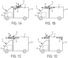
FIG. 1A is an illustration of a refrigerated vehicle in accordance with an embodiment of the invention. -
FIG. 1B is an illustration of a refrigerated vehicle in accordance with an embodiment of the invention. -
FIG. 1C is an illustration of a refrigerated vehicle in accordance with an embodiment of the invention. -
FIG. 1D is an illustration of a refrigerated vehicle in accordance with an embodiment of the invention. -
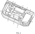
FIG. 2 is a perspective view of a first module of a transport refrigeration unit (TRU) in accordance with an embodiment of the invention. -
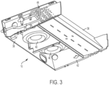
FIG. 3 is a perspective view of a second module of a transport refrigeration unit (TRU) in accordance with an embodiment of the invention. -
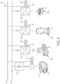
FIG. 4 is a schematic diagram illustrating a direct current (DC) architecture of a transport refrigeration unit (TRU) in accordance with an embodiment of the invention; and -
FIG. 5 is a schematic diagram illustrating a feedback loop of a direct current (DC) architecture of a transport refrigeration unit (TRU) in accordance with an embodiment of the invention. - As will be described below, a system architecture is provided for complete operation on a direct current (DC) bus. The system architecture includes DC powered brushless or brushed fans, DC powered compressors and provides for DC power integration into a truck and/or other support equipment. The system architecture can be provided for high-voltage operations (e.g., 600VDC+) or low voltage operations (e.g., 36V DC or 48V DC) to leverage existing refrigeration components and future power supply systems.
- With reference to
FIGS. 1A, 1B, 1C and1D, exemplary refrigerated vehicles 2, 4, 6 and 8 are shown. Each refrigerated vehicle 2, 4, 6 and 8 has at least one refrigerated compartment ortrailer 10 that is formed to define aninterior 11, which is maintained at a desired temperature by a transport refrigeration unit (TRU) 12 during operational conditions, and acab 13. Thecab 13 houses anengine 14 that is configured to drive movements of the refrigerated vehicles 2, 4, 6 and 8 and theirrespective trailers 10. As will be described below with additional reference toFIGS. 2 and3 , the TRU 12 includes afirst module 15 that can be mounted on the exterior of thetrailer 10 and asecond module 16 that can be mounted within theinterior 11 of thetrailer 10. Thefirst module 15, which may be referred to as a condenser sub-assembly, includes condensing and compressing elements of the refrigeration unit. Thesecond module 16, which may be referred to as an evaporator sub-assembly, includes an evaporator of the refrigeration unit. - As shown in
FIG. 1A , the refrigerated vehicle 2 has a "roof top" arrangement. Here, thefirst module 15 is mounted on the roof of thetrailer 10 and thesecond module 16 is mounted to the underside of the top of thetrailer 10 within theinterior 11. As shown inFIG. 1B , the refrigerated vehicle 4 has a "recessed" arrangement in which thefirst module 15 is mounted within a recessed area provided in the roof of thecab 12 and thesecond module 16 is mounted adjacent to thefirst module 15 and to the underside of the top of thetrailer 10 within theinterior 11. As shown inFIG. 1C , the refrigerated vehicle 6 has a "mono-block" arrangement. Here, thefirst module 15 is mounted to a front wall of thetrailer 10 above thecab 12 and thesecond module 16 is connected to thefirst module 15 through an insulated wall of thetrailer 10 so as to effectively form a single unit. As shown inFIG. 1D , the refrigerated vehicle 8 has a "split" arrangement in which thefirst module 15 is mounted to the front wall of thetrailer 10 and thesecond module 16 is mounted at the rear of thetrailer 10 within theinterior 11. - With reference to
FIG. 2 , thefirst module 15 may include anouter framework 20 that can be mounted for example to thetrailer 10 and provides support for components therein. Aninternal panel 22, which is attached to theframework 20, and provides additional support for the components therein, divides thefirst module 15 into first andsecond compartments first compartment 24 is acompressor 28, acondenser 30, amicrocontroller 32 andtubing 34 for carrying refrigerant between thecompressor 28, thecondenser 30 and thesecond module 16. Within thesecond compartment 26 is apower converter 36 connected to one or more electrical power supplies. One or more fan assemblies or heat sinks (not shown) may also be provided in thesecond compartment 26 to maintain thepower converter 36 at a desired temperature. - With reference to
FIG. 3 , thesecond module 16 may include anouter framework 38 that can be mounted to the interior of thetrailer 10 and provides support for the components therein. Thesecond module 16 may also include anevaporator 40 andevaporator fans 42 for providing a flow of air over theevaporator 40.Tubing 44 may also be provided for carrying refrigerant to the evaporator 40 from thetubing 34 of thefirst module 14. - With reference to
FIG. 4 , it is seen that theTRU 12 is configured to cool the interior 11 of thetrailer 10. In accordance with embodiments and, as shown inFIG. 4 , theTRU 12 has or is associated with a direct current (DC)architecture 401 that includes acommunications bus 41, aDC power bus 42, a first voltage control unit (VCU) 43, asecond VCU 44 at least one or more energy storage unit 45 and at least one or more DC poweredload 46. Thefirst VCU 43 may include a first DC/DC power converter 430, which is coupled to theDC power bus 42, and a firstlocal controller 431. The firstlocal controller 431 is coupled to thecommunications bus 41 and to the first DC/DC power converter 430. The firstlocal controller 431 is thus disposed and configured to receive DC/DC power conversion commands from theDC communications bus 41 and to control the first DC/DC power converter 430 accordingly. Thesecond VCU 44 may include a second DC/DC power converter 440, which is coupled to theDC power bus 42, and a secondlocal controller 441. The secondlocal controller 441 is coupled to thecommunications bus 41 and to the second DC/DC power converter 440. The secondlocal controller 441 is thus disposed and configured to receive DC/DC power conversion commands from theDC communications bus 41 and to control the second DC/DC power converter 440 accordingly. - The energy storage unit 45 is configured to provide to the DC power bus 42 a quantity of DC power via the first DC/
DC power converter 430 of thefirst VCU 43 in accordance with the control exerted on the first DC/DC power converter 430 by the firstlocal controller 431 of thefirst VCU 43. The DC poweredload 46 is configured to receive from the DC power bus 42 a quantity of DC power via the second DC/DC power converter 440 of thesecond VCU 44 in accordance with the control exerted on the second DC/DC power converter 440 by the secondlocal controller 441 of thesecond VCU 44. - In accordance with embodiments, the
DC power bus 42 can be provided to operate in high or low voltage modes and can carry 36-48 VDC and/or up to 600 VDC or more. In accordance with further embodiments, the energy storage unit 45 may include or be provided as abattery bank 450 with the DC poweredload 46 including or being provided as a DC poweredcompressor 460. In the latter case, the DC poweredcompressor 460 may be thecompressor 28 of the first module 15 (seeFIG. 2 ). - In accordance with further embodiments and, as shown in
FIG. 4 , theTRU 12 may also include aDC power generator 47, a third VCU 48 and a secondary DC powered load 49. In such cases, theDC power generator 47 would be coupled to theDC power bus 42 via adiode element 470, for example, and would be controllable by agenerator controller 471, which is coupled to thecommunications bus 41. Thegenerator controller 471 is thus disposed and configured to receive DC power generation commands from theDC communications bus 41 and to control theDC power generator 47 accordingly. The third VCU 48 may include a third DC/DC power converter 480, which is coupled to theDC power bus 42, and a thirdlocal controller 481. The thirdlocal controller 481 is coupled to thecommunications bus 41 and to the third DC/DC power converter 480. The thirdlocal controller 481 is thus disposed and configured to receive DC/DC power conversion commands from theDC communications bus 41 and to control the third DC/DC power converter 480 accordingly. The secondary DC powered load 49 is configured to receive from the DC power bus 42 a quantity of DC power via the third DC/DC converter 480 of the third VCU 48 in accordance with the control exerted on the third DC/DC power converter 480 by the thirdlocal controller 481 of the third VCU 48. - In accordance with embodiments, the
DC power generator 47 may be provided as a diesel generator or, in some cases, as theengine 14 of the refrigerated vehicle 2, 4, 6 and 8 (seeFIG. 1 ). The secondary DC powered load 49 may include or be provided as a brushless or brushedfan 490 of the one or more fan assemblies of thefirst module 15 or as anevaporator fan 42 of the second module 16 (seeFIGS. 2 and3 ). - With reference to
FIG. 5 , theTRU 12 may also include acontrol element 50. As shown inFIG. 5 , thecontrol element 50 may be coupled to any one or all of the firstlocal controller 431, the secondlocal controller 441, thegenerator controller 471 and the thirdlocal controller 481 via thecommunications bus 41 and may be receptive or in possession of target DC/DC power conversion and generation data for each of the first, second andthird VCUs DC power generator 47 as well as actual DC/DC power conversion and generation data. With such a feedback loop configuration 501, thecontrol element 50 may be configured to issue DC/DC power conversion commands to each of the firstlocal controller 431, the secondlocal controller 441, thegenerator controller 471 and the thirdlocal controller 481 and to issue DC power generation commands to thegenerator controller 471 based on differences between the target DC/DC power conversion and generation data and the actual DC/DC power conversion and generation data. - In accordance with embodiments, the
control element 50 may include a processing unit 51, a memory unit 52 and a networking unit 53 coupled to thecommunications bus 41. The memory unit 52 has executable instructions stored thereon, which, when executed cause the processing unit 51 to be receptive of the actual DC/DC power conversion and generation data, to determine the differences between the actual DC/DC power conversion and generation data and the target DC/DC power conversion and generation data and to issue the DC/DC power conversion and generation commands in accordance with the differences. - With the configurations described above, a DC to alternating current (AC) conversion step can be removed from, for example, the
battery bank 450 to the compressor and the fans. This can lead to a ~3-~8% energy consumption reduction among other advantages. In addition, by removing a DC to AC conversion step, cost and weight penalties associated with having to include conversion equipment in theTRU 12 are avoided or removed. - While the invention is provided in detail in connection with only a limited number of embodiments, it should be readily understood that the invention is not limited to such disclosed embodiments. Rather, the invention can be modified to incorporate any number of variations, alterations, substitutions or equivalent arrangements not heretofore described, but which are commensurate with the scope of the invention as defined by the appended claims.
- Additionally, while various embodiments of the invention have been described, it is to be understood that the exemplary embodiment(s) may include only some of the described exemplary aspects. Accordingly, the invention is not to be seen as limited by the foregoing description, but is only limited by the scope of the appended claims.
Claims (11)
- A transport refrigeration unit (TRU) (12) direct current (DC) architecture (401), comprising:a communications bus (41);a DC power bus (42);first and second voltage control units (VCUs) respectively (43, 44) comprising a DC/DC converter (430, 440) coupled to the DC power bus and a local controller (431, 441) coupled to the communications bus and to the DC/DC converter;an energy storage unit (45) configured to provide to the DC power bus a quantity of DC power via the DC/DC converter of the first VCU in accordance with control exerted thereon by the local controller of the first VCU;a DC powered load (46) configured to receive from the DC power bus a quantity of DC power via the DC/DC converter of the second VCU in accordance with control exerted thereon by the local controller of the second VCU;a DC power generator (47) coupled to the DC power bus (42) and controllable by a generator controller (471) coupled to the communications bus (41);a third VCU (48) comprising a DC/DC converter (480) coupled to the DC power bus and a local controller (481) coupled to the communications bus and to the DC/DC converter;a secondary DC powered load (49) configured to receive from the DC power bus a quantity of DC power via the DC/DC converter of the third VCU in accordance with control exerted thereon by the local controller of the third VCU;a feedback loop (501) coupled to each local controller (431, 441, 471, 481); anda control unit (50) disposed in signal communication with each of the VCUs via the communication bus (41) and configured to control operations of each of the local controllers in accordance with data retrieved from the corresponding feedback loop, whereinthe control unit (50) is configured to issue DC/DC power conversion commands to each of the local controllers (431, 441, 481) and the generator controller (471) and to issue DC power generation commands to the generator controller (471) based on differences between target DC/DC power conversion and generation data and actual DC/DC power conversion and generation data.
- The TRU (12) according to claim 1, wherein the DC power bus (42) carries 36-48 VDC and up to 600 VDC or more.
- The TRU (12) according to claim 1, wherein the energy storage unit (45) comprises a battery bank and the DC powered load (46) comprises a DC powered compressor.
- The TRU (12) according to claim 1, further comprising a diode element (470) electrically interposed between the DC power generator (47) and the DC power bus (42).
- The TRU (12) according to claim 1, wherein the DC power generator (47) comprises a diesel generator and the secondary DC powered load (49) comprises a fan.
- A transport vehicle (2; 4; 6; 8), comprising:a trailer (10);an engine (14) to drive movements of the trailer; anda transport refrigeration unit (TRU) (12) of any preceding claim configured to cool an interior of the trailer.
- The transport vehicle of claim 6, wherein the DC power generator comprises a diesel generator of the engine.
- A method of operating the transport refrigeration unit (TRU) (12) direct current (DC) architecture (401) according to any of claims 1 to 5, the method comprising:providing a quantity of DC power from the energy storage unit (45) to the DC power bus (42) via the DC/DC converter of the first voltage control unit (VCU) (43) in accordance with control exerted thereon by the local controller (431) of the first VCU;receiving a quantity of DC power at the DC powered load (46) from the DC power bus via the DC/DC converter of the second VCU (44) in accordance with control exerted thereon by the local controller (441) of the second VCU;providing a quantity of DC power from the DC power generator (47) to the DC power bus (42) in accordance with control exerted thereon by the generator controller (471);receiving a quantity of DC power at the secondary DC powered load (49) from the DC power bus via the DC/DC converter of the third VCU (48) in accordance with control exerted thereon by the local controller (481) of the third VCU; andcontrolling operations of each of the local controllers (431, 441; 471; 481), using the control unit (50) disposed in signal communication with each of the VCUs via the communication bus (41), in accordance with data retrieved from the feedback loop (501) coupled to each local controller (431; 441; 471; 481),wherein DC/DC power conversion commands are issued to each of the local controllers (431, 441, 481) and the generator controller (471) and DC power generation commands are issued to the generator controller (471) based on differences between target DC/DC power conversion and generation data and actual DC/DC power conversion and generation data.
- The method according to claim 8, wherein the DC power bus (42) carries 36-48 VDC.
- The method according to claim 8, wherein the DC power bus (42) carries up to 600 VDC or more.
- The method according to claim 8, wherein the energy storage unit (45) comprises a battery bank, the DC power generator (47) comprises a diesel generator and the DC powered load (46) comprises a DC powered compressor or a fan.
Applications Claiming Priority (2)
| Application Number | Priority Date | Filing Date | Title |
|---|---|---|---|
| US201762448511P | 2017-01-20 | 2017-01-20 | |
| PCT/US2018/014425 WO2018136738A2 (en) | 2017-01-20 | 2018-01-19 | Transport refrigeration unit (tru) direct current (dc) architecture |
Publications (2)
| Publication Number | Publication Date |
|---|---|
| EP3571074A2 EP3571074A2 (en) | 2019-11-27 |
| EP3571074B1 true EP3571074B1 (en) | 2024-04-10 |
Family
ID=61868851
Family Applications (1)
| Application Number | Title | Priority Date | Filing Date |
|---|---|---|---|
| EP18715153.5A Active EP3571074B1 (en) | 2017-01-20 | 2018-01-19 | Transport refrigeration unit (tru) direct current (dc) architecture |
Country Status (4)
| Country | Link |
|---|---|
| US (1) | US11135893B2 (en) |
| EP (1) | EP3571074B1 (en) |
| CN (1) | CN110431027B (en) |
| WO (1) | WO2018136738A2 (en) |
Families Citing this family (8)
| Publication number | Priority date | Publication date | Assignee | Title |
|---|---|---|---|---|
| EP3626488B1 (en) * | 2018-09-20 | 2022-05-11 | Zanotti S.p.A. | A method for controlling the voltage output of a power distribution system for a transport conditioning unit |
| EP4477487A3 (en) * | 2018-09-28 | 2025-03-12 | Carrier Corporation | Electrical architecture for powering transportation refrigeration unit |
| US11489431B2 (en) * | 2019-12-30 | 2022-11-01 | Thermo King Corporation | Transport climate control system power architecture |
| US12409709B2 (en) | 2022-01-04 | 2025-09-09 | Carrier Corporation | Medium-to-high voltage power system for a transport refrigeration unit |
| EP4206007A1 (en) | 2022-01-04 | 2023-07-05 | Carrier Corporation | Low voltage power system for a transport refrigeration unit |
| EP4234289B1 (en) * | 2022-02-28 | 2026-04-29 | Carrier Corporation | Transport refrigeration system having direct current power sources |
| EP4415197A1 (en) * | 2023-02-09 | 2024-08-14 | B/E Aerospace, Inc. | High voltage direct current powered aircraft appliances |
| US20240083219A1 (en) * | 2023-10-12 | 2024-03-14 | Future Air Solutions Tech LLC | Air treatment unit for recreational vehicles |
Family Cites Families (25)
| Publication number | Priority date | Publication date | Assignee | Title |
|---|---|---|---|---|
| US20020070712A1 (en) * | 2000-12-13 | 2002-06-13 | Arul Senthil G. | Hand-held remote-control device with high-capacitance power supply |
| US6622505B2 (en) | 2001-06-08 | 2003-09-23 | Thermo King Corporation | Alternator/invertor refrigeration unit |
| US7743616B2 (en) * | 2006-10-12 | 2010-06-29 | Thermo King Corporation | Control system for a generator |
| JP4325678B2 (en) | 2007-01-26 | 2009-09-02 | ダイキン工業株式会社 | Refrigeration equipment for refrigeration vehicles |
| US20100045105A1 (en) * | 2007-01-31 | 2010-02-25 | Carrier Corporation | Integrated multiple power conversion system for transport refrigeration units |
| GB2446810C (en) | 2007-02-22 | 2016-01-20 | Bowman Power Group Ltd | An auxiliary power generation apparatus |
| BRPI0721710A2 (en) * | 2007-06-07 | 2013-01-22 | Carrier Corp | Method and system for electric power supply for auxiliary electric loads |
| CN101688709A (en) | 2007-07-06 | 2010-03-31 | 开利公司 | Transport refrigeration series hybrid power supply |
| US20110030399A1 (en) | 2008-01-08 | 2011-02-10 | Carrier Corporation | Refrigerant system with fuel cell for electricity generation |
| US8260494B2 (en) | 2008-04-02 | 2012-09-04 | International Truck Intellectual Property Company, Llc | Method and apparatus to optimize energy efficiency of air compressor in vehicle air brake application |
| US7646116B2 (en) * | 2008-05-22 | 2010-01-12 | Petra Solar Inc. | Method and system for balancing power distribution in DC to DC power conversion |
| US8295950B1 (en) | 2008-07-02 | 2012-10-23 | Jerry Lee Wordsworth | Intelligent power management system |
| CN105711376B (en) * | 2008-09-17 | 2019-01-01 | 开利公司 | Electric transportation refrigeration unit |
| CN101898500B (en) * | 2010-07-19 | 2011-12-07 | 浙江博阳压缩机有限公司 | DC-driven mobile refrigeration equipment |
| WO2012138500A1 (en) | 2011-04-04 | 2012-10-11 | Carrier Corporation | Transport refrigeration system and method for operating |
| EP2694304B1 (en) * | 2011-04-04 | 2018-05-02 | Carrier Corporation | Semi-electric mobile refrigerated system |
| US9634593B2 (en) * | 2012-04-26 | 2017-04-25 | Emerson Climate Technologies, Inc. | System and method for permanent magnet motor control |
| EP2844506B1 (en) | 2012-05-01 | 2021-03-31 | Carrier Corporation | Transport refrigeration system having electric fans |
| US20140060097A1 (en) | 2012-08-31 | 2014-03-06 | Philip PERREAULT | Refrigerated truck battery back-up system and related methods |
| US9586458B2 (en) | 2014-02-28 | 2017-03-07 | Enow, Inc. | Tractor trailer refrigeration unit |
| US20170232817A1 (en) * | 2014-07-01 | 2017-08-17 | David Hutchison | Air conditioning system for tractor trailers |
| PL224189B1 (en) | 2014-07-07 | 2016-11-30 | Zachodniopomorski Univ Tech W Szczecinie | Method for reduction of energy consumption by thermoelectric refrigerator and the thermoelectric refrigerator |
| DE102014224660A1 (en) * | 2014-12-02 | 2016-06-02 | Robert Bosch Gmbh | Electronic component and wiring system group for an electrically driven means of transportation |
| WO2016153841A1 (en) | 2015-03-20 | 2016-09-29 | Carrier Corporation | Transportation refrigeration unit with multiple compressors |
| EP3304679B1 (en) * | 2015-05-31 | 2021-04-07 | Thermo King Corporation | Method and system for extending autonomous operation of a self-contained climate controlled storage unit |
-
2018
- 2018-01-19 EP EP18715153.5A patent/EP3571074B1/en active Active
- 2018-01-19 CN CN201880007756.5A patent/CN110431027B/en active Active
- 2018-01-19 WO PCT/US2018/014425 patent/WO2018136738A2/en not_active Ceased
- 2018-01-19 US US16/476,490 patent/US11135893B2/en active Active
Also Published As
| Publication number | Publication date |
|---|---|
| CN110431027B (en) | 2023-05-09 |
| CN110431027A (en) | 2019-11-08 |
| WO2018136738A2 (en) | 2018-07-26 |
| US11135893B2 (en) | 2021-10-05 |
| WO2018136738A3 (en) | 2018-08-30 |
| US20200055366A1 (en) | 2020-02-20 |
| EP3571074A2 (en) | 2019-11-27 |
Similar Documents
| Publication | Publication Date | Title |
|---|---|---|
| EP3571074B1 (en) | Transport refrigeration unit (tru) direct current (dc) architecture | |
| EP3634792B1 (en) | Hybrid power conversion system for a refrigerated transport vehicle and method | |
| EP4157656B1 (en) | Electric mobile refrigeration unit | |
| US11059352B2 (en) | Methods and systems for augmenting a vehicle powered transport climate control system | |
| EP3647089B1 (en) | Method and system for controlling a mild hybrid system that powers a transport climate system | |
| US11554638B2 (en) | Methods and systems for preserving autonomous operation of a transport climate control system | |
| EP3647091B1 (en) | Reconfigurable utility power input with passive voltage booster | |
| US12233683B2 (en) | Optimized power distribution to transport climate control systems amongst one or more electric supply equipment stations | |
| US11707962B2 (en) | Trailer transport refrigeration unit assisted by a tractor auxiliary power unit | |
| US20200189361A1 (en) | Hybrid-power transport refrigeration systems | |
| US20080257622A1 (en) | Motor Vehicle Comprising a Solar Module | |
| EP3481665A1 (en) | High voltage system for a transport refrigeration unit | |
| EP3440416A1 (en) | Transport refrigeration unit with battery boost | |
| CN105711376A (en) | Electric transport refrigeration unit | |
| US12334835B2 (en) | Transport climate control system with a self-configuring matrix power converter | |
| EP4238791B1 (en) | Transport refrigeration unit with multiple voltage source arrangements | |
| US12522051B2 (en) | Low voltage power system for a transport refrigeration unit | |
| US20210362567A1 (en) | Zone isolation air flow system for semi-trailer reefers | |
| US20130181673A1 (en) | Charger for a battery for supplying power to a drive motor of a motor vehicle |
Legal Events
| Date | Code | Title | Description |
|---|---|---|---|
| STAA | Information on the status of an ep patent application or granted ep patent |
Free format text: STATUS: UNKNOWN |
|
| STAA | Information on the status of an ep patent application or granted ep patent |
Free format text: STATUS: THE INTERNATIONAL PUBLICATION HAS BEEN MADE |
|
| PUAI | Public reference made under article 153(3) epc to a published international application that has entered the european phase |
Free format text: ORIGINAL CODE: 0009012 |
|
| STAA | Information on the status of an ep patent application or granted ep patent |
Free format text: STATUS: REQUEST FOR EXAMINATION WAS MADE |
|
| 17P | Request for examination filed |
Effective date: 20190730 |
|
| AK | Designated contracting states |
Kind code of ref document: A2 Designated state(s): AL AT BE BG CH CY CZ DE DK EE ES FI FR GB GR HR HU IE IS IT LI LT LU LV MC MK MT NL NO PL PT RO RS SE SI SK SM TR |
|
| AX | Request for extension of the european patent |
Extension state: BA ME |
|
| DAV | Request for validation of the european patent (deleted) | ||
| DAX | Request for extension of the european patent (deleted) | ||
| STAA | Information on the status of an ep patent application or granted ep patent |
Free format text: STATUS: EXAMINATION IS IN PROGRESS |
|
| 17Q | First examination report despatched |
Effective date: 20201112 |
|
| RIC1 | Information provided on ipc code assigned before grant |
Ipc: H02J 7/34 20060101ALI20230314BHEP Ipc: H02J 7/32 20060101ALI20230314BHEP Ipc: B60H 1/32 20060101ALI20230314BHEP Ipc: H02J 1/00 20060101ALI20230314BHEP Ipc: B60H 1/00 20060101AFI20230314BHEP |
|
| GRAP | Despatch of communication of intention to grant a patent |
Free format text: ORIGINAL CODE: EPIDOSNIGR1 |
|
| STAA | Information on the status of an ep patent application or granted ep patent |
Free format text: STATUS: GRANT OF PATENT IS INTENDED |
|
| INTG | Intention to grant announced |
Effective date: 20230503 |
|
| GRAJ | Information related to disapproval of communication of intention to grant by the applicant or resumption of examination proceedings by the epo deleted |
Free format text: ORIGINAL CODE: EPIDOSDIGR1 |
|
| STAA | Information on the status of an ep patent application or granted ep patent |
Free format text: STATUS: EXAMINATION IS IN PROGRESS |
|
| INTC | Intention to grant announced (deleted) | ||
| GRAP | Despatch of communication of intention to grant a patent |
Free format text: ORIGINAL CODE: EPIDOSNIGR1 |
|
| STAA | Information on the status of an ep patent application or granted ep patent |
Free format text: STATUS: GRANT OF PATENT IS INTENDED |
|
| INTG | Intention to grant announced |
Effective date: 20231024 |
|
| GRAS | Grant fee paid |
Free format text: ORIGINAL CODE: EPIDOSNIGR3 |
|
| GRAA | (expected) grant |
Free format text: ORIGINAL CODE: 0009210 |
|
| STAA | Information on the status of an ep patent application or granted ep patent |
Free format text: STATUS: THE PATENT HAS BEEN GRANTED |
|
| AK | Designated contracting states |
Kind code of ref document: B1 Designated state(s): AL AT BE BG CH CY CZ DE DK EE ES FI FR GB GR HR HU IE IS IT LI LT LU LV MC MK MT NL NO PL PT RO RS SE SI SK SM TR |
|
| REG | Reference to a national code |
Ref country code: GB Ref legal event code: FG4D |
|
| REG | Reference to a national code |
Ref country code: CH Ref legal event code: EP |
|
| REG | Reference to a national code |
Ref country code: DE Ref legal event code: R096 Ref document number: 602018067821 Country of ref document: DE |
|
| REG | Reference to a national code |
Ref country code: IE Ref legal event code: FG4D |
|
| REG | Reference to a national code |
Ref country code: NL Ref legal event code: FP |
|
| RAP4 | Party data changed (patent owner data changed or rights of a patent transferred) |
Owner name: CARRIER CORPORATION |
|
| REG | Reference to a national code |
Ref country code: LT Ref legal event code: MG9D |
|
| REG | Reference to a national code |
Ref country code: AT Ref legal event code: MK05 Ref document number: 1674587 Country of ref document: AT Kind code of ref document: T Effective date: 20240410 |
|
| PG25 | Lapsed in a contracting state [announced via postgrant information from national office to epo] |
Ref country code: IS Free format text: LAPSE BECAUSE OF FAILURE TO SUBMIT A TRANSLATION OF THE DESCRIPTION OR TO PAY THE FEE WITHIN THE PRESCRIBED TIME-LIMIT Effective date: 20240810 |
|
| PG25 | Lapsed in a contracting state [announced via postgrant information from national office to epo] |
Ref country code: BG Free format text: LAPSE BECAUSE OF FAILURE TO SUBMIT A TRANSLATION OF THE DESCRIPTION OR TO PAY THE FEE WITHIN THE PRESCRIBED TIME-LIMIT Effective date: 20240410 |
|
| PG25 | Lapsed in a contracting state [announced via postgrant information from national office to epo] |
Ref country code: HR Free format text: LAPSE BECAUSE OF FAILURE TO SUBMIT A TRANSLATION OF THE DESCRIPTION OR TO PAY THE FEE WITHIN THE PRESCRIBED TIME-LIMIT Effective date: 20240410 Ref country code: FI Free format text: LAPSE BECAUSE OF FAILURE TO SUBMIT A TRANSLATION OF THE DESCRIPTION OR TO PAY THE FEE WITHIN THE PRESCRIBED TIME-LIMIT Effective date: 20240410 |
|
| PG25 | Lapsed in a contracting state [announced via postgrant information from national office to epo] |
Ref country code: GR Free format text: LAPSE BECAUSE OF FAILURE TO SUBMIT A TRANSLATION OF THE DESCRIPTION OR TO PAY THE FEE WITHIN THE PRESCRIBED TIME-LIMIT Effective date: 20240711 |
|
| PG25 | Lapsed in a contracting state [announced via postgrant information from national office to epo] |
Ref country code: PT Free format text: LAPSE BECAUSE OF FAILURE TO SUBMIT A TRANSLATION OF THE DESCRIPTION OR TO PAY THE FEE WITHIN THE PRESCRIBED TIME-LIMIT Effective date: 20240812 |
|
| PG25 | Lapsed in a contracting state [announced via postgrant information from national office to epo] |
Ref country code: ES Free format text: LAPSE BECAUSE OF FAILURE TO SUBMIT A TRANSLATION OF THE DESCRIPTION OR TO PAY THE FEE WITHIN THE PRESCRIBED TIME-LIMIT Effective date: 20240410 |
|
| PG25 | Lapsed in a contracting state [announced via postgrant information from national office to epo] |
Ref country code: AT Free format text: LAPSE BECAUSE OF FAILURE TO SUBMIT A TRANSLATION OF THE DESCRIPTION OR TO PAY THE FEE WITHIN THE PRESCRIBED TIME-LIMIT Effective date: 20240410 |
|
| PG25 | Lapsed in a contracting state [announced via postgrant information from national office to epo] |
Ref country code: PL Free format text: LAPSE BECAUSE OF FAILURE TO SUBMIT A TRANSLATION OF THE DESCRIPTION OR TO PAY THE FEE WITHIN THE PRESCRIBED TIME-LIMIT Effective date: 20240410 |
|
| PG25 | Lapsed in a contracting state [announced via postgrant information from national office to epo] |
Ref country code: LV Free format text: LAPSE BECAUSE OF FAILURE TO SUBMIT A TRANSLATION OF THE DESCRIPTION OR TO PAY THE FEE WITHIN THE PRESCRIBED TIME-LIMIT Effective date: 20240410 |
|
| PG25 | Lapsed in a contracting state [announced via postgrant information from national office to epo] |
Ref country code: PT Free format text: LAPSE BECAUSE OF FAILURE TO SUBMIT A TRANSLATION OF THE DESCRIPTION OR TO PAY THE FEE WITHIN THE PRESCRIBED TIME-LIMIT Effective date: 20240812 Ref country code: PL Free format text: LAPSE BECAUSE OF FAILURE TO SUBMIT A TRANSLATION OF THE DESCRIPTION OR TO PAY THE FEE WITHIN THE PRESCRIBED TIME-LIMIT Effective date: 20240410 Ref country code: NO Free format text: LAPSE BECAUSE OF FAILURE TO SUBMIT A TRANSLATION OF THE DESCRIPTION OR TO PAY THE FEE WITHIN THE PRESCRIBED TIME-LIMIT Effective date: 20240710 Ref country code: LV Free format text: LAPSE BECAUSE OF FAILURE TO SUBMIT A TRANSLATION OF THE DESCRIPTION OR TO PAY THE FEE WITHIN THE PRESCRIBED TIME-LIMIT Effective date: 20240410 Ref country code: IS Free format text: LAPSE BECAUSE OF FAILURE TO SUBMIT A TRANSLATION OF THE DESCRIPTION OR TO PAY THE FEE WITHIN THE PRESCRIBED TIME-LIMIT Effective date: 20240810 Ref country code: HR Free format text: LAPSE BECAUSE OF FAILURE TO SUBMIT A TRANSLATION OF THE DESCRIPTION OR TO PAY THE FEE WITHIN THE PRESCRIBED TIME-LIMIT Effective date: 20240410 Ref country code: GR Free format text: LAPSE BECAUSE OF FAILURE TO SUBMIT A TRANSLATION OF THE DESCRIPTION OR TO PAY THE FEE WITHIN THE PRESCRIBED TIME-LIMIT Effective date: 20240711 Ref country code: FI Free format text: LAPSE BECAUSE OF FAILURE TO SUBMIT A TRANSLATION OF THE DESCRIPTION OR TO PAY THE FEE WITHIN THE PRESCRIBED TIME-LIMIT Effective date: 20240410 Ref country code: ES Free format text: LAPSE BECAUSE OF FAILURE TO SUBMIT A TRANSLATION OF THE DESCRIPTION OR TO PAY THE FEE WITHIN THE PRESCRIBED TIME-LIMIT Effective date: 20240410 Ref country code: BG Free format text: LAPSE BECAUSE OF FAILURE TO SUBMIT A TRANSLATION OF THE DESCRIPTION OR TO PAY THE FEE WITHIN THE PRESCRIBED TIME-LIMIT Effective date: 20240410 Ref country code: AT Free format text: LAPSE BECAUSE OF FAILURE TO SUBMIT A TRANSLATION OF THE DESCRIPTION OR TO PAY THE FEE WITHIN THE PRESCRIBED TIME-LIMIT Effective date: 20240410 Ref country code: RS Free format text: LAPSE BECAUSE OF FAILURE TO SUBMIT A TRANSLATION OF THE DESCRIPTION OR TO PAY THE FEE WITHIN THE PRESCRIBED TIME-LIMIT Effective date: 20240710 |
|
| REG | Reference to a national code |
Ref country code: DE Ref legal event code: R097 Ref document number: 602018067821 Country of ref document: DE |
|
| PG25 | Lapsed in a contracting state [announced via postgrant information from national office to epo] |
Ref country code: DK Free format text: LAPSE BECAUSE OF FAILURE TO SUBMIT A TRANSLATION OF THE DESCRIPTION OR TO PAY THE FEE WITHIN THE PRESCRIBED TIME-LIMIT Effective date: 20240410 |
|
| PGFP | Annual fee paid to national office [announced via postgrant information from national office to epo] |
Ref country code: NL Payment date: 20241219 Year of fee payment: 8 |
|
| PG25 | Lapsed in a contracting state [announced via postgrant information from national office to epo] |
Ref country code: EE Free format text: LAPSE BECAUSE OF FAILURE TO SUBMIT A TRANSLATION OF THE DESCRIPTION OR TO PAY THE FEE WITHIN THE PRESCRIBED TIME-LIMIT Effective date: 20240410 |
|
| PG25 | Lapsed in a contracting state [announced via postgrant information from national office to epo] |
Ref country code: CZ Free format text: LAPSE BECAUSE OF FAILURE TO SUBMIT A TRANSLATION OF THE DESCRIPTION OR TO PAY THE FEE WITHIN THE PRESCRIBED TIME-LIMIT Effective date: 20240410 |
|
| PG25 | Lapsed in a contracting state [announced via postgrant information from national office to epo] |
Ref country code: RO Free format text: LAPSE BECAUSE OF FAILURE TO SUBMIT A TRANSLATION OF THE DESCRIPTION OR TO PAY THE FEE WITHIN THE PRESCRIBED TIME-LIMIT Effective date: 20240410 Ref country code: SK Free format text: LAPSE BECAUSE OF FAILURE TO SUBMIT A TRANSLATION OF THE DESCRIPTION OR TO PAY THE FEE WITHIN THE PRESCRIBED TIME-LIMIT Effective date: 20240410 |
|
| PG25 | Lapsed in a contracting state [announced via postgrant information from national office to epo] |
Ref country code: SM Free format text: LAPSE BECAUSE OF FAILURE TO SUBMIT A TRANSLATION OF THE DESCRIPTION OR TO PAY THE FEE WITHIN THE PRESCRIBED TIME-LIMIT Effective date: 20240410 |
|
| PG25 | Lapsed in a contracting state [announced via postgrant information from national office to epo] |
Ref country code: SM Free format text: LAPSE BECAUSE OF FAILURE TO SUBMIT A TRANSLATION OF THE DESCRIPTION OR TO PAY THE FEE WITHIN THE PRESCRIBED TIME-LIMIT Effective date: 20240410 Ref country code: SK Free format text: LAPSE BECAUSE OF FAILURE TO SUBMIT A TRANSLATION OF THE DESCRIPTION OR TO PAY THE FEE WITHIN THE PRESCRIBED TIME-LIMIT Effective date: 20240410 Ref country code: RO Free format text: LAPSE BECAUSE OF FAILURE TO SUBMIT A TRANSLATION OF THE DESCRIPTION OR TO PAY THE FEE WITHIN THE PRESCRIBED TIME-LIMIT Effective date: 20240410 Ref country code: EE Free format text: LAPSE BECAUSE OF FAILURE TO SUBMIT A TRANSLATION OF THE DESCRIPTION OR TO PAY THE FEE WITHIN THE PRESCRIBED TIME-LIMIT Effective date: 20240410 Ref country code: DK Free format text: LAPSE BECAUSE OF FAILURE TO SUBMIT A TRANSLATION OF THE DESCRIPTION OR TO PAY THE FEE WITHIN THE PRESCRIBED TIME-LIMIT Effective date: 20240410 Ref country code: CZ Free format text: LAPSE BECAUSE OF FAILURE TO SUBMIT A TRANSLATION OF THE DESCRIPTION OR TO PAY THE FEE WITHIN THE PRESCRIBED TIME-LIMIT Effective date: 20240410 |
|
| PG25 | Lapsed in a contracting state [announced via postgrant information from national office to epo] |
Ref country code: IT Free format text: LAPSE BECAUSE OF FAILURE TO SUBMIT A TRANSLATION OF THE DESCRIPTION OR TO PAY THE FEE WITHIN THE PRESCRIBED TIME-LIMIT Effective date: 20240410 |
|
| PLBE | No opposition filed within time limit |
Free format text: ORIGINAL CODE: 0009261 |
|
| STAA | Information on the status of an ep patent application or granted ep patent |
Free format text: STATUS: NO OPPOSITION FILED WITHIN TIME LIMIT |
|
| 26N | No opposition filed |
Effective date: 20250113 |
|
| PG25 | Lapsed in a contracting state [announced via postgrant information from national office to epo] |
Ref country code: SI Free format text: LAPSE BECAUSE OF FAILURE TO SUBMIT A TRANSLATION OF THE DESCRIPTION OR TO PAY THE FEE WITHIN THE PRESCRIBED TIME-LIMIT Effective date: 20240410 |
|
| REG | Reference to a national code |
Ref country code: CH Ref legal event code: PL |
|
| PG25 | Lapsed in a contracting state [announced via postgrant information from national office to epo] |
Ref country code: SE Free format text: LAPSE BECAUSE OF FAILURE TO SUBMIT A TRANSLATION OF THE DESCRIPTION OR TO PAY THE FEE WITHIN THE PRESCRIBED TIME-LIMIT Effective date: 20240410 |
|
| PG25 | Lapsed in a contracting state [announced via postgrant information from national office to epo] |
Ref country code: MC Free format text: LAPSE BECAUSE OF FAILURE TO SUBMIT A TRANSLATION OF THE DESCRIPTION OR TO PAY THE FEE WITHIN THE PRESCRIBED TIME-LIMIT Effective date: 20240410 Ref country code: LU Free format text: LAPSE BECAUSE OF NON-PAYMENT OF DUE FEES Effective date: 20250119 |
|
| PG25 | Lapsed in a contracting state [announced via postgrant information from national office to epo] |
Ref country code: BE Free format text: LAPSE BECAUSE OF NON-PAYMENT OF DUE FEES Effective date: 20250131 |
|
| PG25 | Lapsed in a contracting state [announced via postgrant information from national office to epo] |
Ref country code: CH Free format text: LAPSE BECAUSE OF NON-PAYMENT OF DUE FEES Effective date: 20250131 |
|
| REG | Reference to a national code |
Ref country code: BE Ref legal event code: MM Effective date: 20250131 |
|
| PGFP | Annual fee paid to national office [announced via postgrant information from national office to epo] |
Ref country code: GB Payment date: 20251220 Year of fee payment: 9 |
|
| PGFP | Annual fee paid to national office [announced via postgrant information from national office to epo] |
Ref country code: FR Payment date: 20251218 Year of fee payment: 9 |
|
| PG25 | Lapsed in a contracting state [announced via postgrant information from national office to epo] |
Ref country code: IE Free format text: LAPSE BECAUSE OF NON-PAYMENT OF DUE FEES Effective date: 20250119 |
|
| PGFP | Annual fee paid to national office [announced via postgrant information from national office to epo] |
Ref country code: DE Payment date: 20251217 Year of fee payment: 9 |