EP3571002B1 - Wire dispenser for a laser metal wire deposition machine with a cooling circuit ; corresponding laser metal wire deposition machine ; method of performing laser metal wire deposition on a workpiece with such wire dispenser - Google Patents
Wire dispenser for a laser metal wire deposition machine with a cooling circuit ; corresponding laser metal wire deposition machine ; method of performing laser metal wire deposition on a workpiece with such wire dispenser Download PDFInfo
- Publication number
- EP3571002B1 EP3571002B1 EP18700903.0A EP18700903A EP3571002B1 EP 3571002 B1 EP3571002 B1 EP 3571002B1 EP 18700903 A EP18700903 A EP 18700903A EP 3571002 B1 EP3571002 B1 EP 3571002B1
- Authority
- EP
- European Patent Office
- Prior art keywords
- nozzle
- wire
- metal
- laser
- bore
- Prior art date
- Legal status (The legal status is an assumption and is not a legal conclusion. Google has not performed a legal analysis and makes no representation as to the accuracy of the status listed.)
- Active
Links
Images




Classifications
-
- B—PERFORMING OPERATIONS; TRANSPORTING
- B23—MACHINE TOOLS; METAL-WORKING NOT OTHERWISE PROVIDED FOR
- B23K—SOLDERING OR UNSOLDERING; WELDING; CLADDING OR PLATING BY SOLDERING OR WELDING; CUTTING BY APPLYING HEAT LOCALLY, e.g. FLAME CUTTING; WORKING BY LASER BEAM
- B23K3/00—Tools, devices or special appurtenances for soldering, e.g. brazing, or unsoldering, not specially adapted for particular methods
- B23K3/06—Solder feeding devices; Solder melting pans
- B23K3/0607—Solder feeding devices
- B23K3/063—Solder feeding devices for wire feeding
-
- B—PERFORMING OPERATIONS; TRANSPORTING
- B23—MACHINE TOOLS; METAL-WORKING NOT OTHERWISE PROVIDED FOR
- B23K—SOLDERING OR UNSOLDERING; WELDING; CLADDING OR PLATING BY SOLDERING OR WELDING; CUTTING BY APPLYING HEAT LOCALLY, e.g. FLAME CUTTING; WORKING BY LASER BEAM
- B23K26/00—Working by laser beam, e.g. welding, cutting or boring
- B23K26/34—Laser welding for purposes other than joining
-
- B—PERFORMING OPERATIONS; TRANSPORTING
- B23—MACHINE TOOLS; METAL-WORKING NOT OTHERWISE PROVIDED FOR
- B23K—SOLDERING OR UNSOLDERING; WELDING; CLADDING OR PLATING BY SOLDERING OR WELDING; CUTTING BY APPLYING HEAT LOCALLY, e.g. FLAME CUTTING; WORKING BY LASER BEAM
- B23K26/00—Working by laser beam, e.g. welding, cutting or boring
- B23K26/34—Laser welding for purposes other than joining
- B23K26/342—Build-up welding
-
- B—PERFORMING OPERATIONS; TRANSPORTING
- B23—MACHINE TOOLS; METAL-WORKING NOT OTHERWISE PROVIDED FOR
- B23K—SOLDERING OR UNSOLDERING; WELDING; CLADDING OR PLATING BY SOLDERING OR WELDING; CUTTING BY APPLYING HEAT LOCALLY, e.g. FLAME CUTTING; WORKING BY LASER BEAM
- B23K1/00—Soldering, e.g. brazing, or unsoldering
- B23K1/005—Soldering by means of radiant energy
- B23K1/0056—Soldering by means of radiant energy soldering by means of beams, e.g. lasers, electron beams [EB]
-
- B—PERFORMING OPERATIONS; TRANSPORTING
- B23—MACHINE TOOLS; METAL-WORKING NOT OTHERWISE PROVIDED FOR
- B23K—SOLDERING OR UNSOLDERING; WELDING; CLADDING OR PLATING BY SOLDERING OR WELDING; CUTTING BY APPLYING HEAT LOCALLY, e.g. FLAME CUTTING; WORKING BY LASER BEAM
- B23K26/00—Working by laser beam, e.g. welding, cutting or boring
- B23K26/70—Auxiliary operations or equipment
- B23K26/702—Auxiliary equipment
- B23K26/703—Cooling arrangements
-
- B—PERFORMING OPERATIONS; TRANSPORTING
- B23—MACHINE TOOLS; METAL-WORKING NOT OTHERWISE PROVIDED FOR
- B23K—SOLDERING OR UNSOLDERING; WELDING; CLADDING OR PLATING BY SOLDERING OR WELDING; CUTTING BY APPLYING HEAT LOCALLY, e.g. FLAME CUTTING; WORKING BY LASER BEAM
- B23K26/00—Working by laser beam, e.g. welding, cutting or boring
- B23K26/08—Devices involving relative movement between laser beam and workpiece
- B23K26/0869—Devices involving movement of the laser head in at least one axial direction
- B23K26/0876—Devices involving movement of the laser head in at least one axial direction in at least two axial directions
- B23K26/0884—Devices involving movement of the laser head in at least one axial direction in at least two axial directions in at least three axial directions, e.g. manipulators, robots
-
- B—PERFORMING OPERATIONS; TRANSPORTING
- B23—MACHINE TOOLS; METAL-WORKING NOT OTHERWISE PROVIDED FOR
- B23K—SOLDERING OR UNSOLDERING; WELDING; CLADDING OR PLATING BY SOLDERING OR WELDING; CUTTING BY APPLYING HEAT LOCALLY, e.g. FLAME CUTTING; WORKING BY LASER BEAM
- B23K26/00—Working by laser beam, e.g. welding, cutting or boring
- B23K26/14—Working by laser beam, e.g. welding, cutting or boring using a fluid stream, e.g. a jet of gas, in conjunction with the laser beam; Nozzles therefor
- B23K26/1462—Nozzles; Features related to nozzles
- B23K26/1464—Supply to, or discharge from, nozzles of media, e.g. gas, powder, wire
- B23K26/147—Features outside the nozzle for feeding the fluid stream towards the workpiece
-
- Y—GENERAL TAGGING OF NEW TECHNOLOGICAL DEVELOPMENTS; GENERAL TAGGING OF CROSS-SECTIONAL TECHNOLOGIES SPANNING OVER SEVERAL SECTIONS OF THE IPC; TECHNICAL SUBJECTS COVERED BY FORMER USPC CROSS-REFERENCE ART COLLECTIONS [XRACs] AND DIGESTS
- Y02—TECHNOLOGIES OR APPLICATIONS FOR MITIGATION OR ADAPTATION AGAINST CLIMATE CHANGE
- Y02P—CLIMATE CHANGE MITIGATION TECHNOLOGIES IN THE PRODUCTION OR PROCESSING OF GOODS
- Y02P10/00—Technologies related to metal processing
- Y02P10/25—Process efficiency
Definitions
- the present invention relates to a wire dispenser for laser metal deposition machine according to the preamble of claim 1 (see for example DE 39 28 092 Al), for the cooling of the wire dispenser.
- the present invention relates also to a laser metal wire deposition machine comprising such wire dispenser (see claim 12), and to a method of performing laser metal wire deposition on a workpiece (see claim 15).
- LMDw Laser metal wire deposition
- AM additive manufacturing
- Fig. 1A shows a robot 11 of a manufacturing cell 1 for performing LMDw on a workpiece in the form of a fan case mount ring 14 (see Fig. 1B ).
- the robot 11 has an arm 12 which carries a head 13.
- the head 13 includes a laser unit 2 which emits a laser beam and a wire dispenser 3 which is positioned in the manner of an arm at the side of the laser unit 2 and dispenses a wire.
- the laser beam and the wire meet at a laser metal wire deposition site on the fan case mount ring 14.
- the fan case mount ring 14 is rotatably supported on a turntable 15 which is shown in Fig. 1B and which rotates the fan case mount ring 14 to move the laser metal wire deposition site 16 relative to the fan case mount ring 14, so that a circumferential layer or bead 141 (see Fig. 1C ) is deposited around the fan case mount ring 14.
- a flange is then built up layer by layer (bead by bead) and, after all of the layers (beads) have been deposited, the flange may be machined to give the flange its final shape.
- Fig. 2 is a diagrammatic representation of the tool configuration at the laser metal wire deposition site 16.
- the laser unit 2 emits a laser beam 21 towards the LMDw site 16, and the wire dispenser 3 feeds a wire 4 towards the LMDw site 16.
- the power of the laser beam is of the order of 6 kW.
- the laser beam 21 melts the wire 4 and a new layer 142 is laid down on a substrate 143 (e.g. on the fan case mount ring 14, or on a layer 141 which has already been deposited on the fan case mount ring 14).
- This formation of the new layer 142 is a form of additive layer manufacturing and, in the context of the fan case mount ring 14, serves to form or build up a flange.
- a control unit controls the position of the laser unit 2 and the feeding of wire by the wire dispenser 3, in response to inputs such as desired layer height and desired tool (laser unit) offset, and the measured height of the surface of the substrate 143 as the substrate 143 moves in the direction 1431.
- the wire dispenser 3 includes a nozzle 5 at the forward or distal end of the wire dispenser 3, and the wire 4 is fed out of the front end or tip of the nozzle 5.
- the nozzle 5 is close to the LMDw site 16, and during the deposition process (as the new layer 142 is laid down) the nozzle 5 is exposed to elevated temperatures (e.g. from radiant heat from the LMDw site 16) and reflections of the laser beam 21.
- the tip of the nozzle 5 can start to melt, and the metal material (e.g. copper) of the nozzle 5 may contaminate the new layer 142, which may for example be a titanium layer.
- the metal material e.g. copper
- the additive layer manufacturing process (the deposition process of the new layer 142) to be continuous and without interruptions for reasons of manufacturing efficiency.
- the manufacturing process has to be interrupted and the nozzle 5 has to be replaced with a new nozzle.
- These interruptions in the continuous process lead to a lower (slower) deposition rate (measured in kg/hour) and to the incurring of expenditure in the form of the cost of providing new nozzles.
- the melting of the tip of the nozzle 5 means that, for example, the nozzle needs to be replaced after the laying down of a maximum of 6 beads (layers), which corresponds to an operation time of under 30 minutes.
- the deposition process is typically performed in an enclosed argon gas environment (in a chamber or tent).
- the chamber or tent must be opened, the nozzle replaced and the chamber or tent re-filled with argon gas so that the subsequent deposition process achieves the required purity level.
- the time taken to replace a nozzle is about 5 to 10 minutes.
- the onset of significant melting of the nozzle may be delayed by reducing the deposition rate by decreasing the power of the laser beam.
- this reduces the productivity of the manufacturing process because it would take longer to deposit a particular amount of material on the workpiece.
- Reducing the deposition rate by reducing the laser power goes against current business trends which are pushing for increasing the deposition rate to increase manufacturing efficiency (productivity) by, for example, increasing the laser power.
- a wire dispenser for a laser metal wire deposition machine according to the present invention is defined in claim 1.
- the onset of significant melting of the nozzle may be delayed or prevented, and thus manufacturing efficiency may be increased by reducing or eliminating the downtime (the interruptions) associated with replacing the nozzle. Also there is the saving of the cost of having to provide replacement nozzles or parts thereof.
- the deposition process has been run for over ten hours without having to replace a nozzle, compared with the typical time period of 30 minutes that was previously experienced before a nozzle needed to be replaced. It is envisaged that the manufacturing cell which uses the present invention may make faster deposition rates possible by increasing the laser power (e.g. from 6 kW to 12 kW).
- the metal block may be considered to be acting as a heat sink which absorbs the heat radiated from the LMDw site and the laser light reflected from the LMDw site.
- the metal may give the block sufficient thermal mass, and the thermal energy taken up by the metal block is then carried away by the cooling function of the rear cooling portion.
- the rear cooling portion and the metal front block may comprise a single (monolithic) metal block.
- the rear cooling portion may contain a chamber which forms a front portion of the cooling circuit.
- a coolant inlet pipe may be connected to a front end of the chamber.
- a coolant outlet pipe may be connected to a rear end of the chamber.
- the flow rate of the cooling liquid e.g. water
- the flow rate of the cooling liquid is 0.15 to 0.35 m 3 /hour or 0.2 to 0.3 m 3 /hour.
- the flow rate may be scaled up accordingly.
- the metal block may be given a polished surface to assist with reflecting away scattered laser light.
- An existing nozzle may have a sleeve-like device (metal front block and the rear cooling portion) produced which fits the existing nozzle. Also, the nozzle (if worn out) may be replaced without having to replace the sleeve-like cooling device, and vice versa.
- the thermal control device may be slidably fitted onto the metal nozzle.
- the thermal control device may frictionally grip the metal nozzle.
- the rear cooling portion has a circumferential line of contact with the metal nozzle.
- an outside diameter of the nozzle may substantially match (may be the same as) an internal diameter of the thermal control device.
- a large thermal path (around a full circumference) from the nozzle to the thermal control device increases the effectiveness of keeping the nozzle cool.
- the volume of metal of the metal front block is greater than the volume of metal of that part of the metal nozzle which is seated within the metal front block.
- the nozzle may obstruct the sleeve bore. This may be acceptable because there is no need for a longitudinal passageway along the full length of the sleeve bore for the purpose of supplying gas to the nozzle tip.
- a nozzle which obstructs the sleeve bore helps to ensure a large thermal path for cooling the nozzle.
- a range of thermal control devices may be produced having internal diameters of the sleeve bores which fit the external diameters of the nozzles.
- the longitudinal position of the nozzle in the sleeve bore is such that a front tip of the nozzle is within a range of plus 1mm to minus 5mm of the front face of the front block.
- the cooling circuit of the nozzle unit has an inlet and an outlet at a rear face of the nozzle unit, and a coolant liquid inlet pipe is connected to the inlet and a coolant liquid outlet pipe is connected to the outlet.
- the inlet and outlet pipes By so positioning the inlet and outlet pipes, they may be shielded from being exposed to heat from the LMDw site.
- the inlet and outlet pipes may be soldered to the inlet and the outlet of the nozzle unit to prevent leakage of the coolant liquid.
- the inlet and outlet pipe may each have an internal diameter of 3 to 6 mm, or 3 to 5 mm, or 4 mm.
- the outer diameter may typically be 2 mm greater than the internal diameter.
- the cooling circuit of the nozzle unit is configured to have an inlet temperature of the cooling liquid of 10 to 40 °C, or 10 to 30 °C, or 15 to 25 °C, or 18 to 22 °C, or 20°C.
- a cooling jacket having a cooling circuit is positioned around the duct.
- Such a rearward cooling jacket may be configured so that the cooling circuit of the cooling jacket is connected to the cooling circuit of the nozzle unit.
- cost may be reduced because only one overall cooling circuit needs to be provided which operates at two different locations (one rearward and one forward).
- a laser metal wire deposition machine comprising a laser unit defining a laser beam axis and a wire dispenser according to the present invention is defined in claim 12.
- the wire dispenser is provided as part of an arm which is attached to a side of the laser unit.
- a gas chamber contains the laser unit, the wire dispenser and a jig for supporting a workpiece.
- the jig may be a turntable for rotatably supporting a workpiece such as a cylindrical workpiece.
- the laser unit is arranged to emit a laser beam along the laser beam axis having a power of 4, 5 or 6 kW to 12, 16 or 20 kW.
- the sleeve bore of the thermal control device has a rear bore portion which is in thermal contact with a rear portion of the nozzle and a front bore portion which surrounds a tapered front portion of the nozzle with an annular chamber therebetween.
- the sleeve bore may typically be cylindrical, e.g. circular in cross-section.
- the annular chamber may be filled in, e.g. with reflective material, or may be left as an empty gap.
- the rear bore portion is in thermal contact around a full circumference of the rear portion of the nozzle.
- the thermal control device is asymmetrically positioned around the nozzle.
- the majority of the thermal control device may be positioned on the side of the nozzle remote from the workpiece to make it easier to avoid the thermal control device from clashing with (touching) the workpiece during a deposition procedure.
- the front face of the thermal control device comprises a first portion which is substantially perpendicular to the longitudinal axis of the nozzle and which surrounds the front tip of the nozzle and a second portion which is rearwardly inclined and is offset laterally relative to the longitudinal axis of the nozzle; and the cooling circuit is positioned rearwardly of said second portion.
- the emission axis of the laser beam is less likely to hit the thermal control device during a deposition procedure.
- a method of performing laser metal wire deposition on a workpiece using a laser unit which emits a laser beam along a laser beam axis and a wire dispenser according to the present invention is defined in claim 15.
- the laser metal wire deposition is performed in a gas chamber which contains an inert gas.
- the workpiece is a fan case mount ring and the laser metal wire deposition site is on a flange of the fan case mount ring.
- Fig. 3 shows, in diagrammatic form, an LMDw machine in accordance with the present invention, wherein nozzle tip cooling is retro-fitted onto an existing metal (e.g. copper) nozzle 5.
- existing metal e.g. copper
- the nozzle 5 is arranged to discharge a metal wire 4 along a wire dispensing axis 41 towards an LMDw site 16 on a workpiece 14 which is mounted on a jig 15.
- a metal wire 4 along a wire dispensing axis 41 towards an LMDw site 16 on a workpiece 14 which is mounted on a jig 15.
- portions 4A, 4B of the wire 4 are shown, although in reality the wire 4 is continuous and extends to the LMDw site 16.
- a laser unit 2 is used to emit a laser beam 21 along a laser beam axis 22 to intersect with the wire 4 at the LMDw site 16.
- the nozzle 5 has a through bore 51 which has a front portion 511 and a rear portion 512.
- the wire 4 extends through the bore 51.
- a rear portion 52 of the nozzle 5 has a cylindrical outer surface and a front portion 53 has a tapered outer surface which leads to a front tip 54.
- the nozzle 5 forms part of a nozzle unit 6.
- the other component of the nozzle unit 6 is a thermal control device 7 which serves to cool the nozzle 5 and to shield the nozzle 5 from the heat radiated from the LMDw site 16 and from laser light reflected from the workpiece 14.
- the external surface of the thermal control device 7 may be polished to make it reflective.
- the thermal control device 7 is made of metal (e.g. copper) and has a sleeve-like shape with a sleeve bore 71 which extends from a rear face 72 to a front face 73 of the device 7.
- the nozzle 5 is received in the sleeve bore 71.
- a gap is shown between the rear portion 52 of the nozzle 5 and a rear bore portion 74 of the sleeve bore 71.
- the rear bore portion 74 of the sleeve bore 71 forms a close fit with the rear portion 52 of the nozzle 5 to provide thermal conduction between the nozzle 5 and the device 7.
- a front bore portion 75 of the sleeve bore 71 is spaced away from the tapered front portion 53 of the nozzle 5 and an annular gap 61 is present therebetween.
- the thermal control device 7 has the form of a body which is separated into a solid-metal front block 76 and a hollow rear cooling portion 77.
- the rear cooling portion 77 is hollow because is contains an internal passageway 771 which functions as a cooling circuit having an inlet 771A and an outlet 771B.
- a coolant liquid inlet pipe 78 is soldered to the inlet 771A and a coolant liquid outlet pipe 79 is soldered to the outlet 771B.
- Each pipe 78, 79 has an internal diameter of 4 mm and an external diameter of 6 mm.
- a longitudinal duct 8 has a proximal (inlet or rear) end 81 for receiving the wire 4 and a distal (outlet or front) end 82 for discharging the wire 4.
- the distal end 82 is releasably connected (e.g. screw threadedly connected) to the rear portion 52 of the nozzle 5 and is arranged to feed the wire 4 into the through bore 51 of the nozzle 5.
- the wire 4 may be advanced (fed forwards) by any suitable mechanism (not shown) such as pinch rollers or a pneumatic wire delivery mechanism.
- a cooling jacket 83 with a cooling circuit 84 is positioned around a main tube 85 of the duct 8.
- the cooling circuit 84 may be connected to the cooling circuit 771 so that they function as one circuit, or the two cooling circuits 84, 771 may function independently.
- the nozzle unit 6 (comprising the nozzle 5 and the thermal control unit 7) and the duct 8 form a wire dispenser 9.
- the wire dispenser 9 is supported at one side of the laser unit 2 by means of a support arm 23 which extends from the laser unit 2 to any convenient part of the wire dispenser 9.
- the mass (the thermal mass) of metal of the front block 76 of the thermal control unit 7 may be large enough to act as an effective heat sink.
- the mass of metal of the front block 76 may be selected to be greater (e.g. at least two times greater, or at least three times greater) than the mass of the metal of that part of the nozzle 5 present inside the front portion 75 of the sleeve bore 71 provided inside the front block 76.
- Heat absorbed by the front block 76 may pass rearwardly to the rear cooling portion 77, and then be carried away by the cooling circuit 771. Heat absorbed at and adjacent to the front tip 54 of the nozzle 5 may pass via the rear portion 52 of the nozzle 5 to the rear cooling portion 77, and then be carried away by the cooling circuit 771.
- the inlet temperature of the coolant liquid (e.g. water) received by the cooling circuit 771 may be 20 °C (plus or minus 2 °C) and the flow rate of the coolant may be 0.2 to 0.3 m 3 /hour.
- the coolant liquid e.g. water
- the temperature of the nozzle 5 may be controlled to be kept below the temperature at which the metal of the front tip 54 of the nozzle 5 might start to melt.
- the wire dispenser 9, laser unit 2 and the jig 15 form a machine which is typically contained inside a chamber or tent (not shown) which is filled with an inert gas such as argon during the deposition process on the workpiece 14.
- the nozzle 5 can be prevented from melting for long periods such that the need to replace a melted nozzle can be largely eliminated. This increases the productivity of the LMDw machine. For example, time is not wasted in venting the argon and re-filing the chamber or tent with argon when changing a damaged (melted) nozzle.
- the effective tip cooling will mean that the power of the laser beam 21 may be increased which would increase productivity by increasing the deposition rate.
- the feed rate of the wire 4 would be increased commensurately.
- the thermal control unit 7 is asymmetrically shaped relative to the nozzle 5, with the majority of the body of the unit 7 being above the nozzle 5 and remote from the workpiece 14. Thus, the nozzle 5 should not be restricted in being able to approach closely the workpiece 14 during the deposition process.
- a top front corner of the body of the thermal control unit 7 is chamfered to reduce the risk of clashing with the laser beam 21.
- the front face 73 has a first portion 731 around the sleeve bore 71 which is perpendicular to the axis 41 and a second (upper) portion 732 which is above the first portion 731 and inclined rearwardly.
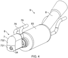
- Figs. 4-8 show a version of a wire dispenser 9 in accordance with the present invention which forms another embodiment.
- Fig. 4 is a perspective front view.
- Fig. 5 is a side view.
- Fig. 6 is a plan view.
- Fig. 7 is a longitudinal sectional view.
- Fig. 8 is longitudinal sectional view similar to Fig. 7 but with some of the sectional detail depicted in solid to make some of the internal features easier to see.
- Figs. 7 and 8 show a variation compared with the wire dispenser 9 of Fig. 3 .
- the sleeve bore 71 of the thermal control unit 7 is not cylindrical along its full length.
- the rear bore portion 74 is cylindrical, but the front bore portion 75 is tapered in the forward direction to match the tapering of the front portion 53 of the nozzle 5.
- Figs. 7 and 8 also show how the nozzle tip 54 is substantially flush with the first portion 731 of the front face 73.
- the nozzle tip 54 may protrude slightly or be recessed slightly.
- the nozzle tip 54 is cooled by being surrounded with the cooling effect provided by the thermal control unit 7, and the nozzle 5 may be prevented from melting.
- the desired amount of cooling may be achieved taking into account the power of the laser beam 21.
- the internal passageway (cooling circuit) of the thermal control unit 7 is provided in the form of a chamber 771C in the rear cooling portion 77.
- the inlet pipe 78 extends to the front of the chamber 771C, and the outlet pipe 79 vents the rear of the chamber 771C.
Landscapes
- Engineering & Computer Science (AREA)
- Physics & Mathematics (AREA)
- Optics & Photonics (AREA)
- Mechanical Engineering (AREA)
- Plasma & Fusion (AREA)
- Robotics (AREA)
- Laser Beam Processing (AREA)
- Coating By Spraying Or Casting (AREA)
Description
- The present invention relates to a wire dispenser for laser metal deposition machine according to the preamble of claim 1 (see for example
DE 39 28 092 Al), for the cooling of the wire dispenser. The present invention relates also to a laser metal wire deposition machine comprising such wire dispenser (see claim 12), and to a method of performing laser metal wire deposition on a workpiece (see claim 15). - Laser metal wire deposition (LMDw) is used in, for example, the aerospace industry and is a form of additive manufacturing (AM). As one example of its use, LMDw may be used to form a flange on a fan case mount ring of a gas turbine engine along a circumferential deposition line.
- Such an example of a known use of LMDw is shown in
Figs. 1A to 1C . -
Fig. 1A shows arobot 11 of amanufacturing cell 1 for performing LMDw on a workpiece in the form of a fan case mount ring 14 (seeFig. 1B ). Therobot 11 has anarm 12 which carries ahead 13. Thehead 13 includes alaser unit 2 which emits a laser beam and awire dispenser 3 which is positioned in the manner of an arm at the side of thelaser unit 2 and dispenses a wire. The laser beam and the wire meet at a laser metal wire deposition site on the fancase mount ring 14. - The fan
case mount ring 14 is rotatably supported on aturntable 15 which is shown inFig. 1B and which rotates the fancase mount ring 14 to move the laser metalwire deposition site 16 relative to the fancase mount ring 14, so that a circumferential layer or bead 141 (seeFig. 1C ) is deposited around the fancase mount ring 14. A flange is then built up layer by layer (bead by bead) and, after all of the layers (beads) have been deposited, the flange may be machined to give the flange its final shape. -
Fig. 2 is a diagrammatic representation of the tool configuration at the laser metalwire deposition site 16. Thelaser unit 2 emits alaser beam 21 towards the LMDwsite 16, and thewire dispenser 3 feeds a wire 4 towards the LMDwsite 16. The power of the laser beam is of the order of 6 kW. - At the LMDw
site 16, thelaser beam 21 melts the wire 4 and anew layer 142 is laid down on a substrate 143 (e.g. on the fancase mount ring 14, or on alayer 141 which has already been deposited on the fan case mount ring 14). This formation of thenew layer 142 is a form of additive layer manufacturing and, in the context of the fancase mount ring 14, serves to form or build up a flange. - A control unit (not shown) controls the position of the
laser unit 2 and the feeding of wire by thewire dispenser 3, in response to inputs such as desired layer height and desired tool (laser unit) offset, and the measured height of the surface of thesubstrate 143 as thesubstrate 143 moves in thedirection 1431. - The
wire dispenser 3 includes anozzle 5 at the forward or distal end of thewire dispenser 3, and the wire 4 is fed out of the front end or tip of thenozzle 5. Thenozzle 5 is close to the LMDwsite 16, and during the deposition process (as thenew layer 142 is laid down) thenozzle 5 is exposed to elevated temperatures (e.g. from radiant heat from the LMDw site 16) and reflections of thelaser beam 21. - Consequently, the tip of the
nozzle 5 can start to melt, and the metal material (e.g. copper) of thenozzle 5 may contaminate thenew layer 142, which may for example be a titanium layer. - It is desirable for the additive layer manufacturing process (the deposition process of the new layer 142) to be continuous and without interruptions for reasons of manufacturing efficiency. However, when the tip of the
nozzle 5 starts to melt, the manufacturing process has to be interrupted and thenozzle 5 has to be replaced with a new nozzle. These interruptions in the continuous process lead to a lower (slower) deposition rate (measured in kg/hour) and to the incurring of expenditure in the form of the cost of providing new nozzles. - The melting of the tip of the
nozzle 5 means that, for example, the nozzle needs to be replaced after the laying down of a maximum of 6 beads (layers), which corresponds to an operation time of under 30 minutes. The deposition process is typically performed in an enclosed argon gas environment (in a chamber or tent). Thus, in order to replace a nozzle, the chamber or tent must be opened, the nozzle replaced and the chamber or tent re-filled with argon gas so that the subsequent deposition process achieves the required purity level. Overall, the time taken to replace a nozzle is about 5 to 10 minutes. - In order to make a nozzle last for a longer period of time, the onset of significant melting of the nozzle may be delayed by reducing the deposition rate by decreasing the power of the laser beam. However, this reduces the productivity of the manufacturing process because it would take longer to deposit a particular amount of material on the workpiece.
- Reducing the deposition rate by reducing the laser power goes against current business trends which are pushing for increasing the deposition rate to increase manufacturing efficiency (productivity) by, for example, increasing the laser power.
- It would be desirable to improve the process of laser metal wire deposition.
- A wire dispenser for a laser metal wire deposition machine according to the present invention is defined in
claim 1. - By providing cooling of the nozzle, the onset of significant melting of the nozzle may be delayed or prevented, and thus manufacturing efficiency may be increased by reducing or eliminating the downtime (the interruptions) associated with replacing the nozzle. Also there is the saving of the cost of having to provide replacement nozzles or parts thereof.
- In a manufacturing cell which uses an embodiment of the present invention, the deposition process has been run for over ten hours without having to replace a nozzle, compared with the typical time period of 30 minutes that was previously experienced before a nozzle needed to be replaced. It is envisaged that the manufacturing cell which uses the present invention may make faster deposition rates possible by increasing the laser power (e.g. from 6 kW to 12 kW).
- The metal block may be considered to be acting as a heat sink which absorbs the heat radiated from the LMDw site and the laser light reflected from the LMDw site. The metal may give the block sufficient thermal mass, and the thermal energy taken up by the metal block is then carried away by the cooling function of the rear cooling portion.
- The rear cooling portion and the metal front block may comprise a single (monolithic) metal block.
- The rear cooling portion may contain a chamber which forms a front portion of the cooling circuit. A coolant inlet pipe may be connected to a front end of the chamber. A coolant outlet pipe may be connected to a rear end of the chamber.
- In some embodiments (e.g. when the laser beam has a power of the order of 6 kW), the flow rate of the cooling liquid (e.g. water) is 0.15 to 0.35 m3/hour or 0.2 to 0.3 m3/hour. When the laser beam has a higher power, the flow rate may be scaled up accordingly.
- The metal block may be given a polished surface to assist with reflecting away scattered laser light.
- An existing nozzle may have a sleeve-like device (metal front block and the rear cooling portion) produced which fits the existing nozzle. Also, the nozzle (if worn out) may be replaced without having to replace the sleeve-like cooling device, and vice versa.
- The thermal control device may be slidably fitted onto the metal nozzle. The thermal control device may frictionally grip the metal nozzle.
- In some embodiments, the rear cooling portion has a circumferential line of contact with the metal nozzle.
- For example, an outside diameter of the nozzle may substantially match (may be the same as) an internal diameter of the thermal control device.
- A large thermal path (around a full circumference) from the nozzle to the thermal control device increases the effectiveness of keeping the nozzle cool.
- In some embodiments, the volume of metal of the metal front block is greater than the volume of metal of that part of the metal nozzle which is seated within the metal front block.
- This helps the metal front block to act as a heat sink sparing the nozzle from heating up and therefore helping to prevent unwanted melting of the nozzle itself.
- The nozzle may obstruct the sleeve bore. This may be acceptable because there is no need for a longitudinal passageway along the full length of the sleeve bore for the purpose of supplying gas to the nozzle tip. A nozzle which obstructs the sleeve bore helps to ensure a large thermal path for cooling the nozzle.
- For a range of existing nozzles of different external diameter, a range of thermal control devices may be produced having internal diameters of the sleeve bores which fit the external diameters of the nozzles.
- The longitudinal position of the nozzle in the sleeve bore is such that a front tip of the nozzle is within a range of plus 1mm to minus 5mm of the front face of the front block. When deciding to what extent the tip of the nozzle should protrude or be recessed relative to the front face of the front block, it may be desirable to aim for it to be flush or just slightly recessed.
- In some embodiments, the cooling circuit of the nozzle unit has an inlet and an outlet at a rear face of the nozzle unit, and a coolant liquid inlet pipe is connected to the inlet and a coolant liquid outlet pipe is connected to the outlet.
- By so positioning the inlet and outlet pipes, they may be shielded from being exposed to heat from the LMDw site.
- The inlet and outlet pipes may be soldered to the inlet and the outlet of the nozzle unit to prevent leakage of the coolant liquid. The inlet and outlet pipe may each have an internal diameter of 3 to 6 mm, or 3 to 5 mm, or 4 mm. The outer diameter may typically be 2 mm greater than the internal diameter.
- In some embodiments, the cooling circuit of the nozzle unit is configured to have an inlet temperature of the cooling liquid of 10 to 40 °C, or 10 to 30 °C, or 15 to 25 °C, or 18 to 22 °C, or 20°C.
- In some embodiments, a cooling jacket having a cooling circuit is positioned around the duct. Such a rearward cooling jacket (remote from the forward point of discharge of the wire adjacent to the LMDw site) may be configured so that the cooling circuit of the cooling jacket is connected to the cooling circuit of the nozzle unit. Thus, cost may be reduced because only one overall cooling circuit needs to be provided which operates at two different locations (one rearward and one forward).
- A laser metal wire deposition machine comprising a laser unit defining a laser beam axis and a wire dispenser according to the present invention is defined in
claim 12. - In some embodiments, the wire dispenser is provided as part of an arm which is attached to a side of the laser unit.
- In some embodiments, a gas chamber contains the laser unit, the wire dispenser and a jig for supporting a workpiece.
- For example, the jig may be a turntable for rotatably supporting a workpiece such as a cylindrical workpiece.
- In some embodiments, the laser unit is arranged to emit a laser beam along the laser beam axis having a power of 4, 5 or 6 kW to 12, 16 or 20 kW.
- In some embodiments, the sleeve bore of the thermal control device has a rear bore portion which is in thermal contact with a rear portion of the nozzle and a front bore portion which surrounds a tapered front portion of the nozzle with an annular chamber therebetween.
- This arrangement reflects the fact that existing nozzles may typically have a tapered front portion and that the sleeve bore may typically be cylindrical, e.g. circular in cross-section. If desired, the annular chamber may be filled in, e.g. with reflective material, or may be left as an empty gap.
- In some embodiments, the rear bore portion is in thermal contact around a full circumference of the rear portion of the nozzle.
- In some embodiments, the thermal control device is asymmetrically positioned around the nozzle.
- Thus the majority of the thermal control device may be positioned on the side of the nozzle remote from the workpiece to make it easier to avoid the thermal control device from clashing with (touching) the workpiece during a deposition procedure.
- In some embodiments, the front face of the thermal control device comprises a first portion which is substantially perpendicular to the longitudinal axis of the nozzle and which surrounds the front tip of the nozzle and a second portion which is rearwardly inclined and is offset laterally relative to the longitudinal axis of the nozzle; and the cooling circuit is positioned rearwardly of said second portion.
- By inclining the second portion of the front face of the thermal control device, the emission axis of the laser beam is less likely to hit the thermal control device during a deposition procedure.
- According to the present invention, a method of performing laser metal wire deposition on a workpiece using a laser unit which emits a laser beam along a laser beam axis and a wire dispenser according to the present invention is defined in
claim 15. - In some embodiments, the laser metal wire deposition is performed in a gas chamber which contains an inert gas.
- In some embodiments, the workpiece is a fan case mount ring and the laser metal wire deposition site is on a flange of the fan case mount ring.
- Some embodiments of the present invention will now be described, by way of example only, with reference to the accompanying drawings in which:-
-
Figs. 1A to 1C show a manufacturing cell of the prior art for perfoming laser metal wire deposition (LMDw) on a fan case mount ring.Fig. 1A is an overall perspective view, andFigs. 1B and 1C are more-detailed perspective views. -
Fig. 2 is a diagrammatic representation of a prior art tool configuration at an LMDw site. -
Fig. 3 is a diagrammatic representation of an LMDw machine in accordance with the present invention, in which the wire dispenser is shown in cross-section. -
Figs. 4-8 show another wire dispenser in accordance with the present invention.Fig. 4 is a perspective front view.Fig. 5 is a side view.Fig. 6 is a plan view.Fig. 7 is a longitudinal sectional view.Fig. 8 is longitudinal sectional view similar toFig. 7 but with some of the sectional detail depicted in solid to make some of the internal features easier to see. - While the invention is susceptible to various modifications and alternative forms, some embodiments are shown by way of example in the drawings and are herein described in detail. It should be understood, however, that the drawings and detailed description of these embodiments are not intended to limit the invention to the particular forms disclosed. On the contrary, the invention covers all modifications, equivalents and alternatives falling within the scope of the present invention as defined by the appended claims.
-
Fig. 3 shows, in diagrammatic form, an LMDw machine in accordance with the present invention, wherein nozzle tip cooling is retro-fitted onto an existing metal (e.g. copper)nozzle 5. - As shown in
Fig. 3 , thenozzle 5 is arranged to discharge a metal wire 4 along awire dispensing axis 41 towards anLMDw site 16 on aworkpiece 14 which is mounted on ajig 15. For the sake of visual clarity, onlyportions LMDw site 16. - A
laser unit 2 is used to emit alaser beam 21 along alaser beam axis 22 to intersect with the wire 4 at theLMDw site 16. - The
nozzle 5 has a throughbore 51 which has afront portion 511 and arear portion 512. The wire 4 extends through thebore 51. - A
rear portion 52 of thenozzle 5 has a cylindrical outer surface and afront portion 53 has a tapered outer surface which leads to afront tip 54. - The
nozzle 5 forms part of anozzle unit 6. The other component of thenozzle unit 6 is athermal control device 7 which serves to cool thenozzle 5 and to shield thenozzle 5 from the heat radiated from theLMDw site 16 and from laser light reflected from theworkpiece 14. To assist with reflecting away the laser light, the external surface of thethermal control device 7 may be polished to make it reflective. - The
thermal control device 7 is made of metal (e.g. copper) and has a sleeve-like shape with a sleeve bore 71 which extends from arear face 72 to afront face 73 of thedevice 7. Thenozzle 5 is received in the sleeve bore 71. InFig. 3 , for reasons of clarity of depiction, a gap is shown between therear portion 52 of thenozzle 5 and arear bore portion 74 of the sleeve bore 71. In reality, therear bore portion 74 of the sleeve bore 71 forms a close fit with therear portion 52 of thenozzle 5 to provide thermal conduction between thenozzle 5 and thedevice 7. - A
front bore portion 75 of the sleeve bore 71 is spaced away from thetapered front portion 53 of thenozzle 5 and anannular gap 61 is present therebetween. - The
thermal control device 7 has the form of a body which is separated into a solid-metal front block 76 and a hollowrear cooling portion 77. Therear cooling portion 77 is hollow because is contains aninternal passageway 771 which functions as a cooling circuit having aninlet 771A and anoutlet 771B. A coolantliquid inlet pipe 78 is soldered to theinlet 771A and a coolantliquid outlet pipe 79 is soldered to theoutlet 771B. Eachpipe - A
longitudinal duct 8 has a proximal (inlet or rear) end 81 for receiving the wire 4 and a distal (outlet or front) end 82 for discharging the wire 4. Thedistal end 82 is releasably connected (e.g. screw threadedly connected) to therear portion 52 of thenozzle 5 and is arranged to feed the wire 4 into the throughbore 51 of thenozzle 5. - The wire 4 may be advanced (fed forwards) by any suitable mechanism (not shown) such as pinch rollers or a pneumatic wire delivery mechanism.
- A cooling
jacket 83 with acooling circuit 84 is positioned around amain tube 85 of theduct 8. Thecooling circuit 84 may be connected to thecooling circuit 771 so that they function as one circuit, or the twocooling circuits - The nozzle unit 6 (comprising the
nozzle 5 and the thermal control unit 7) and theduct 8 form awire dispenser 9. - The
wire dispenser 9 is supported at one side of thelaser unit 2 by means of asupport arm 23 which extends from thelaser unit 2 to any convenient part of thewire dispenser 9. - It is desirable for the mass (the thermal mass) of metal of the
front block 76 of thethermal control unit 7 to be large enough to act as an effective heat sink. Thus, the mass of metal of thefront block 76 may be selected to be greater (e.g. at least two times greater, or at least three times greater) than the mass of the metal of that part of thenozzle 5 present inside thefront portion 75 of the sleeve bore 71 provided inside thefront block 76. - Heat absorbed by the
front block 76 may pass rearwardly to therear cooling portion 77, and then be carried away by thecooling circuit 771. Heat absorbed at and adjacent to thefront tip 54 of thenozzle 5 may pass via therear portion 52 of thenozzle 5 to therear cooling portion 77, and then be carried away by thecooling circuit 771. - For a
laser unit 2 emitting a 6kW laser beam 21, the inlet temperature of the coolant liquid (e.g. water) received by thecooling circuit 771 may be 20 °C (plus or minus 2 °C) and the flow rate of the coolant may be 0.2 to 0.3 m3/hour. - In this way, the temperature of the
nozzle 5 may be controlled to be kept below the temperature at which the metal of thefront tip 54 of thenozzle 5 might start to melt. - The
wire dispenser 9,laser unit 2 and the jig 15 (with its workpiece 14) form a machine which is typically contained inside a chamber or tent (not shown) which is filled with an inert gas such as argon during the deposition process on theworkpiece 14. - Because of the effective tip cooling of the
nozzle 5 provided by thethermal control unit 7, thenozzle 5 can be prevented from melting for long periods such that the need to replace a melted nozzle can be largely eliminated. This increases the productivity of the LMDw machine. For example, time is not wasted in venting the argon and re-filing the chamber or tent with argon when changing a damaged (melted) nozzle. - It is also envisaged that the effective tip cooling will mean that the power of the
laser beam 21 may be increased which would increase productivity by increasing the deposition rate. The feed rate of the wire 4 would be increased commensurately. - The
thermal control unit 7 is asymmetrically shaped relative to thenozzle 5, with the majority of the body of theunit 7 being above thenozzle 5 and remote from theworkpiece 14. Thus, thenozzle 5 should not be restricted in being able to approach closely the workpiece 14 during the deposition process. - A top front corner of the body of the
thermal control unit 7 is chamfered to reduce the risk of clashing with thelaser beam 21. Thefront face 73 has afirst portion 731 around the sleeve bore 71 which is perpendicular to theaxis 41 and a second (upper)portion 732 which is above thefirst portion 731 and inclined rearwardly. -
Figs. 4-8 show a version of awire dispenser 9 in accordance with the present invention which forms another embodiment. -
Fig. 4 is a perspective front view.Fig. 5 is a side view.Fig. 6 is a plan view.Fig. 7 is a longitudinal sectional view.Fig. 8 is longitudinal sectional view similar toFig. 7 but with some of the sectional detail depicted in solid to make some of the internal features easier to see. -
Figs. 7 and8 show a variation compared with thewire dispenser 9 ofFig. 3 . InFigs. 7 and8 , the sleeve bore 71 of thethermal control unit 7 is not cylindrical along its full length. Therear bore portion 74 is cylindrical, but thefront bore portion 75 is tapered in the forward direction to match the tapering of thefront portion 53 of thenozzle 5. -
Figs. 7 and8 also show how thenozzle tip 54 is substantially flush with thefirst portion 731 of thefront face 73. Alternatively, thenozzle tip 54 may protrude slightly or be recessed slightly. - In relation to the embodiment of
Figs. 4 to 8 , it may be seen that thenozzle 5 is effectively shielded by thethermal control unit 7. - The
nozzle tip 54 is cooled by being surrounded with the cooling effect provided by thethermal control unit 7, and thenozzle 5 may be prevented from melting. By supplying chilled water to thethermal control unit 7 at a suitable temperature and flow rate, the desired amount of cooling may be achieved taking into account the power of thelaser beam 21. - From
Figs. 4 to 8 , it may also be seen that the internal passageway (cooling circuit) of thethermal control unit 7 is provided in the form of achamber 771C in therear cooling portion 77. Theinlet pipe 78 extends to the front of thechamber 771C, and theoutlet pipe 79 vents the rear of thechamber 771C.
Claims (15)
- A wire dispenser (9) for a laser metal wire deposition machine, the wire dispenser comprising:a longitudinal duct (8) for guiding a wire (4) from a proximal end (81) to a distal end (82) of the duct; anda nozzle unit (6) comprising a metal nozzle (5) and a thermal control device (7), the metal nozzle (5) being connected to the distal end (82) of the duct (8) and having a through bore (51) for receiving the wire (4) from the distal end (82) of the duct (8) and for discharging the wire adjacent to a laser metal wire deposition site (16);characterized in that:the thermal control device (7) includes a metal front block (76) positioned laterally of a front portion (511) of the through bore (51) of the nozzle (5) and a rear cooling portion (77) positioned laterally of a rear portion (512) of the through bore (51) of the nozzle (5) and rearwardly of the front block (76);the rear cooling portion (77) of the thermal control device (7) contains a cooling circuit (771) for a cooling liquid;the metal front block (76) and the rear cooling portion (77) form a sleeve-like device which is removably fitted onto the metal nozzle (5);the nozzle (5) is of a replaceable type which is removable from the distal end (82) of the duct (8);the thermal control device (7) has a sleeve bore (71) extending from a rear face (72) of the rear cooling portion (77) to a front face (73) of the front block (76) and the nozzle (5) is seated in the sleeve bore (71); andthe longitudinal position of the nozzle (5) in the sleeve bore (71) is such that a front tip (54) of the nozzle is within a range of plus 1mm to minus 5mm of the front face (73) of the front block (76).
- A wire dispenser according to claim 1, wherein the rear cooling portion (77) has a circumferential line of contact with the metal nozzle (5).
- A wire dispenser according to claim 1 or 2, wherein the volume of metal of the metal front block (76) is greater than the volume of metal of that part of the metal nozzle (5) which is seated within the metal front block (76).
- A wire dispenser according to any preceding claim, wherein the nozzle (5) obstructs the sleeve bore (71).
- A wire dispenser according to any preceding claim, wherein the cooling circuit (771) has an inlet (771A) and an outlet (771B) at a rear face (72) of the nozzle unit, and a coolant liquid inlet pipe (78) is connected to the inlet (771A) and a coolant liquid outlet pipe (79) is connected to the outlet (771B).
- A wire dispenser according to any preceding claim, wherein a cooling jacket (83) having a cooling circuit (84) is positioned around the duct (8).
- A wire dispenser according to claim 6, wherein the cooling circuit (84) of the cooling jacket (83) is connected to the cooling circuit (771) of the nozzle unit (6).
- A wire dispenser according to any preceding claim, wherein the sleeve bore (71) has a rear bore portion (74) which is in thermal contact with a rear portion (52) of the nozzle (5) and a front bore portion (75) which surrounds a tapered front portion (53) of the nozzle (5) with an annular gap (61) therebetween.
- A wire dispenser according to claim 8, wherein the rear bore portion (74) is in thermal contact around a full circumference of the rear portion (52) of the nozzle (5).
- A wire dispenser according to any preceding claim, wherein the thermal control device (7) is asymmetrically positioned around the nozzle (5).
- A wire dispenser according to any preceding claim, wherein:
the front face (73) of the metal front block (76) comprises a first portion (731) which is substantially perpendicular to the longitudinal axis of the nozzle (5) and which surrounds the front tip (54) of the nozzle and a second portion (732) which is rearwardly inclined and is offset laterally relative to the longitudinal axis of the nozzle (5). - A laser metal wire deposition machine comprising a laser unit (2) defining a laser beam axis (22) and a wire dispenser (9) according to any preceding claim, wherein the through bore (51) of the metal nozzle (5) of the nozzle unit (6) of the wire dispenser defines a wire dispensing axis (41) and the laser beam axis and the wire dispensing axis meet at the laser metal wire deposition site (16).
- A laser metal wire deposition machine according to claim 12, wherein the wire dispenser (9) is provided as part of an arm (23) which is attached to a side of the laser unit (2).
- A laser metal wire deposition machine according to claim 12 or claim 13, wherein a gas chamber contains the laser unit (2), the wire dispenser (9) and a jig for supporting a workpiece (14).
- A method of performing laser metal wire deposition on a workpiece (14) using a laser unit (2) which emits a laser beam (21) along a laser beam axis (22) and a wire dispenser (9) which is in accordance with any one of claims 1 to 11 and which dispenses a wire (4) along a wire dispensing axis (41) defined by the through bore (51) of the nozzle unit (6), comprising:positioning a laser metal wire deposition site (16) of the workpiece (14) at an intersection of the laser beam axis (22) and the wire dispensing axis (41);emitting the laser beam (21) along the laser beam axis (22); andfeeding the wire (4) along the duct (8) of the wire dispenser (9) and into the through bore (51) of the metal nozzle (5) of the nozzle unit (6) of the wire dispenser, and dispensing the wire (4) along the wire dispensing axis (41) out of the through bore (51) as the wire (4) is consumed by a metal wire deposition operation at the laser metal wire deposition site (16); andcirculating a cooling liquid along the cooling circuit (771) so as to cool the metal front block (76) of the thermal control device (7).
Applications Claiming Priority (2)
| Application Number | Priority Date | Filing Date | Title |
|---|---|---|---|
| GB1700808.7A GB2558897B (en) | 2017-01-17 | 2017-01-17 | Wire dispenser |
| PCT/EP2018/051126 WO2018134264A1 (en) | 2017-01-17 | 2018-01-17 | Wire dispenser, for a laser metal wire deposition machine, with a cooling circuit; corresponding laser metal wire deposition machine; method of performing laser metal wire deposition on a workpiece with such wire dispenser |
Publications (2)
| Publication Number | Publication Date |
|---|---|
| EP3571002A1 EP3571002A1 (en) | 2019-11-27 |
| EP3571002B1 true EP3571002B1 (en) | 2022-03-09 |
Family
ID=58463306
Family Applications (1)
| Application Number | Title | Priority Date | Filing Date |
|---|---|---|---|
| EP18700903.0A Active EP3571002B1 (en) | 2017-01-17 | 2018-01-17 | Wire dispenser for a laser metal wire deposition machine with a cooling circuit ; corresponding laser metal wire deposition machine ; method of performing laser metal wire deposition on a workpiece with such wire dispenser |
Country Status (5)
| Country | Link |
|---|---|
| US (1) | US11498142B2 (en) |
| EP (1) | EP3571002B1 (en) |
| CN (1) | CN110352111B (en) |
| GB (1) | GB2558897B (en) |
| WO (1) | WO2018134264A1 (en) |
Families Citing this family (5)
| Publication number | Priority date | Publication date | Assignee | Title |
|---|---|---|---|---|
| FR3100001B1 (en) * | 2019-08-22 | 2023-04-14 | Safran Aircraft Engines | METHOD FOR ADDITIVE MANUFACTURING OF A TURBOMACHINE PART |
| FR3100003B1 (en) * | 2019-08-22 | 2021-09-03 | Safran Aircraft Engines | METAL LASER DEPOSIT SYSTEM |
| DE102022123550A1 (en) * | 2022-09-14 | 2024-03-14 | HPL Technologies GmbH | Device for deposition welding, and a method for preheating a workpiece |
| WO2024056137A1 (en) * | 2022-09-14 | 2024-03-21 | HPL Technologies GmbH | Apparatus for build-up welding, and a method for preheating a workpiece |
| CN119368932B (en) * | 2024-11-19 | 2025-04-25 | 青岛亨亚不锈钢有限公司 | Laser engraving machine for stainless steel engraving |
Family Cites Families (17)
| Publication number | Priority date | Publication date | Assignee | Title |
|---|---|---|---|---|
| BE792687A (en) * | 1971-12-15 | 1973-06-13 | Philips Nv | WELDING TORCH |
| US4309590A (en) * | 1980-02-29 | 1982-01-05 | Westinghouse Electric Corp. | Narrow groove welding torch |
| US4667083A (en) * | 1986-02-14 | 1987-05-19 | Westinghouse Electric Corp. | Torch for preheating a continuously fed welding wire |
| DE3928092A1 (en) * | 1989-08-25 | 1991-02-28 | Mordike Barry Leslie | Coating metal surfaces using laser-wire coating method - with wire electro-resistance preheated to improve flow capabilities and improve coating qualities |
| EP0838297A1 (en) * | 1996-08-20 | 1998-04-29 | MTA Automation AG | Soldering head used with an automatic soldering apparatus |
| US5958261A (en) * | 1997-07-17 | 1999-09-28 | General Electric Company | Apparatus for welding with preheated filler material |
| CN1159131C (en) * | 2001-12-24 | 2004-07-28 | 北京工业大学 | Laser cladding manufacturing high-speed wire roll special equipment and cladding method |
| US8686317B2 (en) * | 2006-03-15 | 2014-04-01 | Illinois Tool Works Inc. | Removable nozzle-cooling mechanism for welding torches |
| US8297478B2 (en) * | 2008-09-30 | 2012-10-30 | Honeywell International Inc. | Powder feed cylinder assemblies and powder feeders |
| DE102008050992B3 (en) * | 2008-10-13 | 2010-04-01 | Max Ernst | Nozzle for welding using pulsed laser beam, comprises nozzle channel, which is enclosed by nozzle wall, is flow-throughable by working gas and is supplied to welding wire in guiding tube, where receiving tube is provided for guiding tube |
| US20110084053A1 (en) * | 2009-10-12 | 2011-04-14 | Thomas Edward Doyle | Narrow Groove Gas Metal Arc Welding Torch |
| JP3169241U (en) * | 2011-05-11 | 2011-07-21 | 株式会社神戸製鋼所 | Welding torch |
| CN203018917U (en) | 2012-12-31 | 2013-06-26 | 湖南大学 | Laser welding dusting device and fixture |
| CN105188993A (en) * | 2013-03-15 | 2015-12-23 | 麦特法布公司 | Cartridge for an additive manufacturing apparatus and method |
| CN103132072B (en) | 2013-03-20 | 2014-11-12 | 上海交通大学 | Lateral powder feeding nozzle device applied to laser cladding |
| US11440130B2 (en) * | 2016-04-15 | 2022-09-13 | United States Of America As Represented By The Administrator Of Nasa | Process control of electron beam wire additive manufacturing |
| US10350691B2 (en) * | 2017-01-13 | 2019-07-16 | Fca Us Llc | Water cooled wire feed tip collar for laser brazing system |
-
2017
- 2017-01-17 GB GB1700808.7A patent/GB2558897B/en not_active Expired - Fee Related
-
2018
- 2018-01-17 CN CN201880007113.0A patent/CN110352111B/en active Active
- 2018-01-17 US US16/478,047 patent/US11498142B2/en active Active
- 2018-01-17 EP EP18700903.0A patent/EP3571002B1/en active Active
- 2018-01-17 WO PCT/EP2018/051126 patent/WO2018134264A1/en not_active Ceased
Non-Patent Citations (1)
| Title |
|---|
| None * |
Also Published As
| Publication number | Publication date |
|---|---|
| GB201700808D0 (en) | 2017-03-01 |
| US11498142B2 (en) | 2022-11-15 |
| WO2018134264A1 (en) | 2018-07-26 |
| US20190351497A1 (en) | 2019-11-21 |
| CN110352111A (en) | 2019-10-18 |
| GB2558897B (en) | 2019-11-20 |
| CN110352111B (en) | 2022-07-01 |
| GB2558897A (en) | 2018-07-25 |
| EP3571002A1 (en) | 2019-11-27 |
Similar Documents
| Publication | Publication Date | Title |
|---|---|---|
| US11498142B2 (en) | Laser metal wire deposition | |
| JP7471002B2 (en) | Multimode laser devices for metal manufacturing applications | |
| EP0741626B1 (en) | Laser/powdered metal cladding nozzle | |
| JP4272999B2 (en) | Handheld powder supply laser welding torch | |
| US10661343B2 (en) | Smart additive manufacturing device | |
| US20020166846A1 (en) | Powder feed nozzle for laser welding | |
| US8026456B2 (en) | TIG welding system and method | |
| CN102725091B (en) | For integrated protective gas and magnetic field device and the welding system of deep groove welding | |
| US5958261A (en) | Apparatus for welding with preheated filler material | |
| US20130146566A1 (en) | Method and system to laser hot wire layer a pipe end | |
| EP3597354A1 (en) | Laser head for directionally independent additive deposition of hot wire | |
| KR20030064791A (en) | Configurable nozzle baffle apparatus and method | |
| WO2014118620A1 (en) | Method and system to laser hot wire layer a pipe end | |
| JP3268235B2 (en) | Molten steel heating tundish | |
| JP2020534160A (en) | Torch body for thermal bonding | |
| JP2711655B2 (en) | Irradiator for laser welding | |
| US11134559B2 (en) | Plasma torch system | |
| JPH0783947B2 (en) | Powder feeding device for laser cladding | |
| US11433488B2 (en) | Gas dispersion for additive manufacturing | |
| JPH01162578A (en) | Powder plasma overlay welding torch | |
| CN108796496A (en) | For in the system and method for substrate deposit coating | |
| KR101271890B1 (en) | Electro gas arc welder | |
| JP5841342B2 (en) | Nozzle and plasma torch for plasma cutting device | |
| CA3286211A1 (en) | Jet nozzle having a powder unit and a process-gas unit | |
| CN119658048A (en) | Tin explosion-proof welding device for commutator base and control method thereof |
Legal Events
| Date | Code | Title | Description |
|---|---|---|---|
| STAA | Information on the status of an ep patent application or granted ep patent |
Free format text: STATUS: UNKNOWN |
|
| STAA | Information on the status of an ep patent application or granted ep patent |
Free format text: STATUS: THE INTERNATIONAL PUBLICATION HAS BEEN MADE |
|
| PUAI | Public reference made under article 153(3) epc to a published international application that has entered the european phase |
Free format text: ORIGINAL CODE: 0009012 |
|
| STAA | Information on the status of an ep patent application or granted ep patent |
Free format text: STATUS: REQUEST FOR EXAMINATION WAS MADE |
|
| 17P | Request for examination filed |
Effective date: 20190813 |
|
| AK | Designated contracting states |
Kind code of ref document: A1 Designated state(s): AL AT BE BG CH CY CZ DE DK EE ES FI FR GB GR HR HU IE IS IT LI LT LU LV MC MK MT NL NO PL PT RO RS SE SI SK SM TR |
|
| AX | Request for extension of the european patent |
Extension state: BA ME |
|
| DAV | Request for validation of the european patent (deleted) | ||
| DAX | Request for extension of the european patent (deleted) | ||
| GRAP | Despatch of communication of intention to grant a patent |
Free format text: ORIGINAL CODE: EPIDOSNIGR1 |
|
| STAA | Information on the status of an ep patent application or granted ep patent |
Free format text: STATUS: GRANT OF PATENT IS INTENDED |
|
| INTG | Intention to grant announced |
Effective date: 20201103 |
|
| GRAJ | Information related to disapproval of communication of intention to grant by the applicant or resumption of examination proceedings by the epo deleted |
Free format text: ORIGINAL CODE: EPIDOSDIGR1 |
|
| STAA | Information on the status of an ep patent application or granted ep patent |
Free format text: STATUS: REQUEST FOR EXAMINATION WAS MADE |
|
| INTC | Intention to grant announced (deleted) | ||
| GRAP | Despatch of communication of intention to grant a patent |
Free format text: ORIGINAL CODE: EPIDOSNIGR1 |
|
| STAA | Information on the status of an ep patent application or granted ep patent |
Free format text: STATUS: GRANT OF PATENT IS INTENDED |
|
| INTG | Intention to grant announced |
Effective date: 20210416 |
|
| GRAJ | Information related to disapproval of communication of intention to grant by the applicant or resumption of examination proceedings by the epo deleted |
Free format text: ORIGINAL CODE: EPIDOSDIGR1 |
|
| STAA | Information on the status of an ep patent application or granted ep patent |
Free format text: STATUS: REQUEST FOR EXAMINATION WAS MADE |
|
| INTC | Intention to grant announced (deleted) | ||
| GRAP | Despatch of communication of intention to grant a patent |
Free format text: ORIGINAL CODE: EPIDOSNIGR1 |
|
| STAA | Information on the status of an ep patent application or granted ep patent |
Free format text: STATUS: GRANT OF PATENT IS INTENDED |
|
| INTG | Intention to grant announced |
Effective date: 20210930 |
|
| GRAS | Grant fee paid |
Free format text: ORIGINAL CODE: EPIDOSNIGR3 |
|
| GRAA | (expected) grant |
Free format text: ORIGINAL CODE: 0009210 |
|
| STAA | Information on the status of an ep patent application or granted ep patent |
Free format text: STATUS: THE PATENT HAS BEEN GRANTED |
|
| AK | Designated contracting states |
Kind code of ref document: B1 Designated state(s): AL AT BE BG CH CY CZ DE DK EE ES FI FR GB GR HR HU IE IS IT LI LT LU LV MC MK MT NL NO PL PT RO RS SE SI SK SM TR |
|
| REG | Reference to a national code |
Ref country code: CH Ref legal event code: EP Ref country code: AT Ref legal event code: REF Ref document number: 1473710 Country of ref document: AT Kind code of ref document: T Effective date: 20220315 |
|
| REG | Reference to a national code |
Ref country code: IE Ref legal event code: FG4D |
|
| REG | Reference to a national code |
Ref country code: DE Ref legal event code: R096 Ref document number: 602018031913 Country of ref document: DE |
|
| REG | Reference to a national code |
Ref country code: LT Ref legal event code: MG9D |
|
| REG | Reference to a national code |
Ref country code: NL Ref legal event code: MP Effective date: 20220309 |
|
| PG25 | Lapsed in a contracting state [announced via postgrant information from national office to epo] |
Ref country code: SE Free format text: LAPSE BECAUSE OF FAILURE TO SUBMIT A TRANSLATION OF THE DESCRIPTION OR TO PAY THE FEE WITHIN THE PRESCRIBED TIME-LIMIT Effective date: 20220309 Ref country code: RS Free format text: LAPSE BECAUSE OF FAILURE TO SUBMIT A TRANSLATION OF THE DESCRIPTION OR TO PAY THE FEE WITHIN THE PRESCRIBED TIME-LIMIT Effective date: 20220309 Ref country code: NO Free format text: LAPSE BECAUSE OF FAILURE TO SUBMIT A TRANSLATION OF THE DESCRIPTION OR TO PAY THE FEE WITHIN THE PRESCRIBED TIME-LIMIT Effective date: 20220609 Ref country code: LT Free format text: LAPSE BECAUSE OF FAILURE TO SUBMIT A TRANSLATION OF THE DESCRIPTION OR TO PAY THE FEE WITHIN THE PRESCRIBED TIME-LIMIT Effective date: 20220309 Ref country code: HR Free format text: LAPSE BECAUSE OF FAILURE TO SUBMIT A TRANSLATION OF THE DESCRIPTION OR TO PAY THE FEE WITHIN THE PRESCRIBED TIME-LIMIT Effective date: 20220309 Ref country code: BG Free format text: LAPSE BECAUSE OF FAILURE TO SUBMIT A TRANSLATION OF THE DESCRIPTION OR TO PAY THE FEE WITHIN THE PRESCRIBED TIME-LIMIT Effective date: 20220609 |
|
| REG | Reference to a national code |
Ref country code: AT Ref legal event code: MK05 Ref document number: 1473710 Country of ref document: AT Kind code of ref document: T Effective date: 20220309 |
|
| PG25 | Lapsed in a contracting state [announced via postgrant information from national office to epo] |
Ref country code: LV Free format text: LAPSE BECAUSE OF FAILURE TO SUBMIT A TRANSLATION OF THE DESCRIPTION OR TO PAY THE FEE WITHIN THE PRESCRIBED TIME-LIMIT Effective date: 20220309 Ref country code: GR Free format text: LAPSE BECAUSE OF FAILURE TO SUBMIT A TRANSLATION OF THE DESCRIPTION OR TO PAY THE FEE WITHIN THE PRESCRIBED TIME-LIMIT Effective date: 20220610 Ref country code: FI Free format text: LAPSE BECAUSE OF FAILURE TO SUBMIT A TRANSLATION OF THE DESCRIPTION OR TO PAY THE FEE WITHIN THE PRESCRIBED TIME-LIMIT Effective date: 20220309 |
|
| PG25 | Lapsed in a contracting state [announced via postgrant information from national office to epo] |
Ref country code: NL Free format text: LAPSE BECAUSE OF FAILURE TO SUBMIT A TRANSLATION OF THE DESCRIPTION OR TO PAY THE FEE WITHIN THE PRESCRIBED TIME-LIMIT Effective date: 20220309 |
|
| PG25 | Lapsed in a contracting state [announced via postgrant information from national office to epo] |
Ref country code: SM Free format text: LAPSE BECAUSE OF FAILURE TO SUBMIT A TRANSLATION OF THE DESCRIPTION OR TO PAY THE FEE WITHIN THE PRESCRIBED TIME-LIMIT Effective date: 20220309 Ref country code: SK Free format text: LAPSE BECAUSE OF FAILURE TO SUBMIT A TRANSLATION OF THE DESCRIPTION OR TO PAY THE FEE WITHIN THE PRESCRIBED TIME-LIMIT Effective date: 20220309 Ref country code: RO Free format text: LAPSE BECAUSE OF FAILURE TO SUBMIT A TRANSLATION OF THE DESCRIPTION OR TO PAY THE FEE WITHIN THE PRESCRIBED TIME-LIMIT Effective date: 20220309 Ref country code: PT Free format text: LAPSE BECAUSE OF FAILURE TO SUBMIT A TRANSLATION OF THE DESCRIPTION OR TO PAY THE FEE WITHIN THE PRESCRIBED TIME-LIMIT Effective date: 20220711 Ref country code: ES Free format text: LAPSE BECAUSE OF FAILURE TO SUBMIT A TRANSLATION OF THE DESCRIPTION OR TO PAY THE FEE WITHIN THE PRESCRIBED TIME-LIMIT Effective date: 20220309 Ref country code: EE Free format text: LAPSE BECAUSE OF FAILURE TO SUBMIT A TRANSLATION OF THE DESCRIPTION OR TO PAY THE FEE WITHIN THE PRESCRIBED TIME-LIMIT Effective date: 20220309 Ref country code: CZ Free format text: LAPSE BECAUSE OF FAILURE TO SUBMIT A TRANSLATION OF THE DESCRIPTION OR TO PAY THE FEE WITHIN THE PRESCRIBED TIME-LIMIT Effective date: 20220309 Ref country code: AT Free format text: LAPSE BECAUSE OF FAILURE TO SUBMIT A TRANSLATION OF THE DESCRIPTION OR TO PAY THE FEE WITHIN THE PRESCRIBED TIME-LIMIT Effective date: 20220309 |
|
| PG25 | Lapsed in a contracting state [announced via postgrant information from national office to epo] |
Ref country code: PL Free format text: LAPSE BECAUSE OF FAILURE TO SUBMIT A TRANSLATION OF THE DESCRIPTION OR TO PAY THE FEE WITHIN THE PRESCRIBED TIME-LIMIT Effective date: 20220309 Ref country code: IS Free format text: LAPSE BECAUSE OF FAILURE TO SUBMIT A TRANSLATION OF THE DESCRIPTION OR TO PAY THE FEE WITHIN THE PRESCRIBED TIME-LIMIT Effective date: 20220709 Ref country code: AL Free format text: LAPSE BECAUSE OF FAILURE TO SUBMIT A TRANSLATION OF THE DESCRIPTION OR TO PAY THE FEE WITHIN THE PRESCRIBED TIME-LIMIT Effective date: 20220309 |
|
| REG | Reference to a national code |
Ref country code: DE Ref legal event code: R097 Ref document number: 602018031913 Country of ref document: DE |
|
| PLBE | No opposition filed within time limit |
Free format text: ORIGINAL CODE: 0009261 |
|
| STAA | Information on the status of an ep patent application or granted ep patent |
Free format text: STATUS: NO OPPOSITION FILED WITHIN TIME LIMIT |
|
| PG25 | Lapsed in a contracting state [announced via postgrant information from national office to epo] |
Ref country code: DK Free format text: LAPSE BECAUSE OF FAILURE TO SUBMIT A TRANSLATION OF THE DESCRIPTION OR TO PAY THE FEE WITHIN THE PRESCRIBED TIME-LIMIT Effective date: 20220309 |
|
| 26N | No opposition filed |
Effective date: 20221212 |
|
| PG25 | Lapsed in a contracting state [announced via postgrant information from national office to epo] |
Ref country code: SI Free format text: LAPSE BECAUSE OF FAILURE TO SUBMIT A TRANSLATION OF THE DESCRIPTION OR TO PAY THE FEE WITHIN THE PRESCRIBED TIME-LIMIT Effective date: 20220309 |
|
| P01 | Opt-out of the competence of the unified patent court (upc) registered |
Effective date: 20230526 |
|
| PG25 | Lapsed in a contracting state [announced via postgrant information from national office to epo] |
Ref country code: IT Free format text: LAPSE BECAUSE OF FAILURE TO SUBMIT A TRANSLATION OF THE DESCRIPTION OR TO PAY THE FEE WITHIN THE PRESCRIBED TIME-LIMIT Effective date: 20220309 |
|
| REG | Reference to a national code |
Ref country code: CH Ref legal event code: PL |
|
| PG25 | Lapsed in a contracting state [announced via postgrant information from national office to epo] |
Ref country code: LU Free format text: LAPSE BECAUSE OF NON-PAYMENT OF DUE FEES Effective date: 20230117 |
|
| REG | Reference to a national code |
Ref country code: BE Ref legal event code: MM Effective date: 20230131 |
|
| PG25 | Lapsed in a contracting state [announced via postgrant information from national office to epo] |
Ref country code: LI Free format text: LAPSE BECAUSE OF NON-PAYMENT OF DUE FEES Effective date: 20230131 Ref country code: CH Free format text: LAPSE BECAUSE OF NON-PAYMENT OF DUE FEES Effective date: 20230131 |
|
| PG25 | Lapsed in a contracting state [announced via postgrant information from national office to epo] |
Ref country code: BE Free format text: LAPSE BECAUSE OF NON-PAYMENT OF DUE FEES Effective date: 20230131 |
|
| PG25 | Lapsed in a contracting state [announced via postgrant information from national office to epo] |
Ref country code: IE Free format text: LAPSE BECAUSE OF NON-PAYMENT OF DUE FEES Effective date: 20230117 |
|
| PG25 | Lapsed in a contracting state [announced via postgrant information from national office to epo] |
Ref country code: MC Free format text: LAPSE BECAUSE OF FAILURE TO SUBMIT A TRANSLATION OF THE DESCRIPTION OR TO PAY THE FEE WITHIN THE PRESCRIBED TIME-LIMIT Effective date: 20220309 |
|
| PG25 | Lapsed in a contracting state [announced via postgrant information from national office to epo] |
Ref country code: MC Free format text: LAPSE BECAUSE OF FAILURE TO SUBMIT A TRANSLATION OF THE DESCRIPTION OR TO PAY THE FEE WITHIN THE PRESCRIBED TIME-LIMIT Effective date: 20220309 |
|
| PG25 | Lapsed in a contracting state [announced via postgrant information from national office to epo] |
Ref country code: CY Free format text: LAPSE BECAUSE OF FAILURE TO SUBMIT A TRANSLATION OF THE DESCRIPTION OR TO PAY THE FEE WITHIN THE PRESCRIBED TIME-LIMIT; INVALID AB INITIO Effective date: 20180117 |
|
| PG25 | Lapsed in a contracting state [announced via postgrant information from national office to epo] |
Ref country code: HU Free format text: LAPSE BECAUSE OF FAILURE TO SUBMIT A TRANSLATION OF THE DESCRIPTION OR TO PAY THE FEE WITHIN THE PRESCRIBED TIME-LIMIT; INVALID AB INITIO Effective date: 20180117 |
|
| PG25 | Lapsed in a contracting state [announced via postgrant information from national office to epo] |
Ref country code: TR Free format text: LAPSE BECAUSE OF FAILURE TO SUBMIT A TRANSLATION OF THE DESCRIPTION OR TO PAY THE FEE WITHIN THE PRESCRIBED TIME-LIMIT Effective date: 20220309 |
|
| PGFP | Annual fee paid to national office [announced via postgrant information from national office to epo] |
Ref country code: GB Payment date: 20251204 Year of fee payment: 9 |
|
| PGFP | Annual fee paid to national office [announced via postgrant information from national office to epo] |
Ref country code: FR Payment date: 20251128 Year of fee payment: 9 |
|
| PGFP | Annual fee paid to national office [announced via postgrant information from national office to epo] |
Ref country code: DE Payment date: 20251203 Year of fee payment: 9 |