EP3570641A1 - Control method and apparatus for extending runtime on a portable lighting device - Google Patents
Control method and apparatus for extending runtime on a portable lighting device Download PDFInfo
- Publication number
- EP3570641A1 EP3570641A1 EP19160535.1A EP19160535A EP3570641A1 EP 3570641 A1 EP3570641 A1 EP 3570641A1 EP 19160535 A EP19160535 A EP 19160535A EP 3570641 A1 EP3570641 A1 EP 3570641A1
- Authority
- EP
- European Patent Office
- Prior art keywords
- controller
- drive signal
- power source
- lighting unit
- voltage
- Prior art date
- Legal status (The legal status is an assumption and is not a legal conclusion. Google has not performed a legal analysis and makes no representation as to the accuracy of the status listed.)
- Withdrawn
Links
Images





Classifications
-
- H—ELECTRICITY
- H05—ELECTRIC TECHNIQUES NOT OTHERWISE PROVIDED FOR
- H05B—ELECTRIC HEATING; ELECTRIC LIGHT SOURCES NOT OTHERWISE PROVIDED FOR; CIRCUIT ARRANGEMENTS FOR ELECTRIC LIGHT SOURCES, IN GENERAL
- H05B45/00—Circuit arrangements for operating light-emitting diodes [LED]
- H05B45/10—Controlling the intensity of the light
-
- H—ELECTRICITY
- H05—ELECTRIC TECHNIQUES NOT OTHERWISE PROVIDED FOR
- H05B—ELECTRIC HEATING; ELECTRIC LIGHT SOURCES NOT OTHERWISE PROVIDED FOR; CIRCUIT ARRANGEMENTS FOR ELECTRIC LIGHT SOURCES, IN GENERAL
- H05B45/00—Circuit arrangements for operating light-emitting diodes [LED]
- H05B45/30—Driver circuits
- H05B45/395—Linear regulators
-
- F—MECHANICAL ENGINEERING; LIGHTING; HEATING; WEAPONS; BLASTING
- F21—LIGHTING
- F21L—LIGHTING DEVICES OR SYSTEMS THEREOF, BEING PORTABLE OR SPECIALLY ADAPTED FOR TRANSPORTATION
- F21L4/00—Electric lighting devices with self-contained electric batteries or cells
-
- F—MECHANICAL ENGINEERING; LIGHTING; HEATING; WEAPONS; BLASTING
- F21—LIGHTING
- F21V—FUNCTIONAL FEATURES OR DETAILS OF LIGHTING DEVICES OR SYSTEMS THEREOF; STRUCTURAL COMBINATIONS OF LIGHTING DEVICES WITH OTHER ARTICLES, NOT OTHERWISE PROVIDED FOR
- F21V23/00—Arrangement of electric circuit elements in or on lighting devices
- F21V23/02—Arrangement of electric circuit elements in or on lighting devices the elements being transformers, impedances or power supply units, e.g. a transformer with a rectifier
- F21V23/023—Power supplies in a casing
-
- F—MECHANICAL ENGINEERING; LIGHTING; HEATING; WEAPONS; BLASTING
- F21—LIGHTING
- F21V—FUNCTIONAL FEATURES OR DETAILS OF LIGHTING DEVICES OR SYSTEMS THEREOF; STRUCTURAL COMBINATIONS OF LIGHTING DEVICES WITH OTHER ARTICLES, NOT OTHERWISE PROVIDED FOR
- F21V29/00—Protecting lighting devices from thermal damage; Cooling or heating arrangements specially adapted for lighting devices or systems
- F21V29/50—Cooling arrangements
- F21V29/70—Cooling arrangements characterised by passive heat-dissipating elements, e.g. heat-sinks
-
- F—MECHANICAL ENGINEERING; LIGHTING; HEATING; WEAPONS; BLASTING
- F21—LIGHTING
- F21Y—INDEXING SCHEME ASSOCIATED WITH SUBCLASSES F21K, F21L, F21S and F21V, RELATING TO THE FORM OR THE KIND OF THE LIGHT SOURCES OR OF THE COLOUR OF THE LIGHT EMITTED
- F21Y2115/00—Light-generating elements of semiconductor light sources
- F21Y2115/10—Light-emitting diodes [LED]
-
- H—ELECTRICITY
- H05—ELECTRIC TECHNIQUES NOT OTHERWISE PROVIDED FOR
- H05B—ELECTRIC HEATING; ELECTRIC LIGHT SOURCES NOT OTHERWISE PROVIDED FOR; CIRCUIT ARRANGEMENTS FOR ELECTRIC LIGHT SOURCES, IN GENERAL
- H05B45/00—Circuit arrangements for operating light-emitting diodes [LED]
- H05B45/50—Circuit arrangements for operating light-emitting diodes [LED] responsive to malfunctions or undesirable behaviour of LEDs; responsive to LED life; Protective circuits
- H05B45/56—Circuit arrangements for operating light-emitting diodes [LED] responsive to malfunctions or undesirable behaviour of LEDs; responsive to LED life; Protective circuits involving measures to prevent abnormal temperature of the LEDs
-
- Y—GENERAL TAGGING OF NEW TECHNOLOGICAL DEVELOPMENTS; GENERAL TAGGING OF CROSS-SECTIONAL TECHNOLOGIES SPANNING OVER SEVERAL SECTIONS OF THE IPC; TECHNICAL SUBJECTS COVERED BY FORMER USPC CROSS-REFERENCE ART COLLECTIONS [XRACs] AND DIGESTS
- Y02—TECHNOLOGIES OR APPLICATIONS FOR MITIGATION OR ADAPTATION AGAINST CLIMATE CHANGE
- Y02B—CLIMATE CHANGE MITIGATION TECHNOLOGIES RELATED TO BUILDINGS, e.g. HOUSING, HOUSE APPLIANCES OR RELATED END-USER APPLICATIONS
- Y02B20/00—Energy efficient lighting technologies, e.g. halogen lamps or gas discharge lamps
- Y02B20/30—Semiconductor lamps, e.g. solid state lamps [SSL] light emitting diodes [LED] or organic LED [OLED]
Definitions
- This disclosure relates to lighting devices, and in particular to a control method and apparatus for extending runtime of a battery-operated lighting device.
- US. 2016/0348879 for an example of an area lighting device capable of being powered by a battery pack.
- a removeable battery pack is received into a battery receptacle for powering a series of LEDs mounted on a head portion of the light.
- the battery pack may be, for example, a 20V Max lithium-ion sliding battery pack.
- Powering LED lighting devices with a battery power source provides significant benefits in convenience and portability, but also provides limitations on run time. This is generally not a significant problem in smaller scale lighting devices such as flash lights, but as higher power lighting devices become prevalent, battery life presents a significant obstacle. What is needed is a method of conserving and prolonging battery life for such lighting devices.
- a lighting apparatus including a lighting unit arranged to emit light; a switching device disposed between a power source and the lighting unit; and a controller configured to set a drive signal based on a target luminance level of the lighting unit and control a switching operation of the switching device via a drive signal to regulate a supply of electric power from the power source to the lighting unit.
- the controller is configured to monitor a voltage of the power source and periodically adjust the drive signal based on the voltage of the power source.
- a control interface is provided and configured to receive an input from a user indicative of a selected luminance mode and communicate the selected luminance mode to the controller, the controller setting the drive signal based on the selected luminance mode.
- control interface further receives an input from the user indicative of a first mode, where the controller periodically adjusts the drive signal based on the voltage of the power source, or a second mode, where the controller does not adjust the drive signal based on the voltage of the power source.
- the controller is configured to scale down the drive signal when the voltage of the power source is less than a first threshold but greater than a second threshold.
- the lighting apparatus includes a main body and a head portion mounted on the main body, the main body including a battery receptacle for receiving a removable battery pack therein, the head portion including a heat sink.
- the lighting unit includes a light Emitting Diode (LED) mounted on the heat sink.
- a level shifter is disposed between the power source and the controller and configured to provide the controller with a voltage signal indicative of the voltage of the power source.
- a lighting apparatus including a lighting unit arranged to emit light; a switching device disposed between a power source and the lighting unit; and a controller configured to set a drive signal based on a target luminance level of the lighting unit and control a switching operation of the switching device via a drive signal to regulate a supply of electric power from the power source to the lighting unit.
- the controller is configured to adjust the drive signal periodically to reduce the supply of electric power from the power source to the lighting unit after passage of a first predetermined time until a second predetermined time is reached.
- the controller is configured to set a pulse-width modulation (PWM) duty cycle associated with the drive signal based on the target luminance level of the lighting unit and reduce the PWM duty cycle based on a timer that is incremented periodically between the first predetermined time and a second predetermined time.
- PWM pulse-width modulation
- a control interface is provided and configured to receive an input from a user indicative of a selected luminance mode and communicate the selected luminance mode to the controller, the controller setting the drive signal based on the selected luminance mode.
- control interface further receives an input from the user indicative of a first mode, wherein the controller periodically adjusts the drive signal based on the timer between the first predetermined time and the second predetermined time, or a second mode, wherein the controller does not adjust the drive signal based on a timer.
- the controller when the lighting apparatus is turned ON, the controller resets the timer.
- the lighting apparatus includes a main body and a head portion mounted on the main body, the main body including a battery receptacle for receiving a removable battery pack therein, the head portion including a heat sink, wherein the lighting unit includes a chip-on-board (COB) light Emitting Diode (LED) mounted on the heat sink.
- COB chip-on-board
- LED Light Emitting Diode
- a method for controlling a lighting apparatus having a lighting unit arranged to emit light via a controller and a switching device disposed between a power source and the lighting unit.
- the method include: receiving a signal associated with a target luminance level of the lighting unit; setting a drive signal based on the target luminance level; controlling a switching operation of the switching device via the drive signal to regulate supply of electric power from the power supply to the lighting unit; monitoring a voltage of the power supply; and adjusting the drive signal periodically based on the voltage of the power source.
- the controlling a switching operation step includes setting a pulse-width modulation (PWM) duty cycle associated with the drive signal based on the target luminance level of the lighting unit, and modifying the PWM duty cycle based on the voltage of the power source.
- PWM pulse-width modulation
- the method further includes receiving a luminance mode signal from a control interface of the lighting apparatus, the luminance mode signal being indicative of a selected luminance mode, and setting the drive signal based on the selected luminance mode.
- the adjusting step includes scaling down the drive signal when the voltage of the power source is less than a first threshold but greater than a second threshold.
- the main body 110 includes a substantially square-shaped or circular base 112 and a cubical or cylindrical body 114.
- Four vertical side handles 116 are disposed around the main body 110.
- the main body 116 includes a battery receptacle 118 having a hinged door 119 that receives a sliding battery pack (not shown) therein.
- the main body also includes a control interface 130 for receiving control commands from a user.
- the control interface includes push-buttons 131 and 132 and/or other control mechanism for turning the lighting device ON and OFF, mode selection, etc. Mode selection, in an embodiment, correlates to the amount of light output (i.e., brightness) of the LED.
- the control interface 130 also include an 'Eco-Mode' button 134, as described later in detail.
- the head portion 120 includes a Chip-on-Board (COB) LED 122 mounted on a heat sink 124.
- the heat sink 124 may be disc-shaped or cylindrical, including a central base portion 125 and outward-projecting fins 126 projecting radially outwardly from the base portion 125.
- the COB LED 122 is mounted on top of the base portion 125 to allow the heat sink 124 to dissipate heat away from LED 122.
- a diffuser 128 having a semispherical head is mounted on the heat sink base portion 125 around the LED 122.
- a lens 129 is mounted on the main body 110 surrounding the head portion 120 components. In the illustrated example, cut-off views of the diffusor 128 and the lens 129 are shown to expose the heat sink 124 and LED 122.
- Fig. 4 depicts an exemplary block circuit diagram 400 of the lighting device, according to an embodiment.
- the lighting device 100 is provided with LED 122, as described above, receiving power from a removeable battery pack 402 received through the battery receptacle 118.
- a solid-state switch 404 is disposed on the electrical path (i.e., us line 406) between the battery pack 402 and the LED 122.
- a gate of solid-state switch 404 is driven via a gate driver 414 by controller 410.
- Controller 410 in an example, is a programmable device such as a micro-controller, microprocessor, digital signal processor, etc. Controller 410 is powered by a voltage regulator 408 coupled to the bus line 406. The voltage regulator provides the controller 410 with a voltage (e.g., 3.2v) suitable for powering the controller 410.
- controller 410 controls the switching operation of the switch 404 via a pulse-width modulation (PWM) control technique to regulate the amount of electric power being supplied to the LED 122.
- controller 410 receives a mode selection (i.e., luminance mode level selected by the user) from the control interface 130 and sets a PWM duty cycle for the switch 404 accordingly.
- a mode selection i.e., luminance mode level selected by the user
- PWM duty cycle is set to a maximum 100% in a high-luminance mode, to 66% in a medium-luminance mode, and to 33% in a low-luminance mode.
- a PWM count is further set in proportion to the duty cycle on a 0 to 255 graduation scale, at a 0.4 KHz frequency.
- a level shifter 412 is also coupled to the bus line 406 to provide a voltage sense signal to the controller 410 corresponding to the voltage of the bus line 406. As described below, in an embodiment, the controller 410 may use the voltage sense signal to determine the voltage level of the battery pack 402.
- the controller 410 in executing flow process 600, which starts at step 602, the controller 410 begins by setting resetting a timer to zero at step 604. The controller 410 then determines, in step 606, whether to enter 'Eco-mode' based on input from the 'Eco-mode' button 134 of the control interface 130. If not, in step 608, the controller 410 waits for a predetermined amount of time repeats steps 604 and 606 again. Otherwise, in eco-mode, the control proceeds to steps 610-616.
- controller 410 receives a brightness mode selection, as selected by the user, from the control interface 130.
- controller 410 sets the PWM duty cycle (and/or PWM counts) based on brightness mode, as shown in the example provide in Table 1 above.
- controller 410 also determines battery pack 402 voltage. In an embodiment, the controller 410 does this based on the voltage sense signal from the level shifter 412. Subsequently, in step 616, controller 410 scales the PWM duty cycle (and/or PWM counts) based on the battery voltage.
- Process 600 then returns to step 608, where the controller 410 waits for a predetermined amount of time (e.g., 1 second) before it tests the state of charge of the battery again and repeat this process.
- a predetermined amount of time e.g., 1 second
- Table 2 depicts an example of the scaling technique utilized by the controller 410 in step 616.
- PWM count is scaled based on a State of Charge (SOC) Scalar value.
- SOC State of Charge
- Table 3 is an exemplary table utilized by the controller 410 to determine the SOC Scalar relative to the battery pack SOC. TABLE 3 Pack V SOC Scalar 19.85-20.8 1.000 19.8 0.983 19.7 0.950 19.6 0.917 19.5 0.883 19.4 0.850 19.3 0.817 19.2 0.783 19.1 0.750 19 0.717 18.9 0.683 15-18.8V 0.650
- PWM is naturally decremented over the course of the battery discharge cycle.
- turning the light device 100 OFF and back ON causes the controller 410 to pick up where it left off, i.e., at a PWM level corresponding to the state of charge of the battery pack 402.
- Fig. 7 depicts a graphical representation of PWM counts v. battery pack voltage (SOC) chart in the high luminance, medium luminance, and low luminance modes of operation in 'Eco-mode,' as described above, according to an embodiment.
- SOC battery pack voltage
- Fig. 8 is an exemplary flow diagram for controlling power of the lighting device executed by the controller, according to an alternative embodiment.
- the controller 410 reduces the level of brightness of the LED 122 in accordance with a specified scaler that is based on the run time of the LED 122 using battery pack 402.
- the controller 410 in executing flow process 700, which starts at step 702, the controller 410 begins by setting resetting a timer to zero at step 704. The controller 410 then determines, in step 706, whether to enter 'Eco-mode' based on input from the 'Eco-mode' button 134 of the control interface 130. If not, in step 708, the controller 410 waits for a predetermined amount of time repeats steps 704 and 706 again. Otherwise, in eco-mode, the control proceeds to steps 710-716.
- controller 410 receives a brightness mode selection, as selected by the user, from the control interface 130.
- controller 410 sets the PWM duty cycle (and/or PWM counts) based on brightness mode, as shown in the example provide in Table 1 above.
- controller 410 waits for a predetermined amount of time (e.g., 30 seconds).
- controller 410 scales the PWM duty cycle (and/or PWM counts) based on the timer.
- Process 700 then returns to step 706, where it repeats steps 710-716 again as long as the light device 100 is being operated in 'Eco-mode', periodically decrementing the PWM count (or PWM duty cycle).
- Table 4 is an exemplary table utilized by the controller 410 to determine a Eco Mode Scalar relative to the lighting device 100 run time. TABLE 4 Elapsed Time (s) ECO Mode Scalar 0-180 1 240 0.98 300 0.96 360 0.94 420 0.92 480 0.9 540 0.88 600 0.86 660 0.84 720 0.82 780 0.8 840 0.78 900 0.76 930-1140 0.75
- Eco Scalar when Eco Scalar is applied to scale the PWM counts (or PWM duty cycle), PWM is naturally decremented over the course of time for the first several minutes (e.g., 15 minutes) after invocation of 'Eco-mode'. Once a scalar of 0.75 is reached, the controller 410 will continue to operate the light at the same brightness level until either the battery pack is fully discharged or the light is turned OFF. In eco-mode, turning the light device 100 OFF and back ON causes the controller 410 to reset the timer and return the PWM scalar back to 1.
- Example embodiments are provided so that this disclosure will be thorough, and will fully convey the scope to those who are skilled in the art. Numerous specific details are set forth such as examples of specific components, devices, and methods, to provide a thorough understanding of embodiments of the present disclosure. It will be apparent to those skilled in the art that specific details need not be employed, that example embodiments may be embodied in many different forms and that neither should be construed to limit the scope of the disclosure. In some example embodiments, well-known processes, well-known device structures, and well-known technologies are not described in detail.
Landscapes
- Circuit Arrangement For Electric Light Sources In General (AREA)
Abstract
Description
- This disclosure relates to lighting devices, and in particular to a control method and apparatus for extending runtime of a battery-operated lighting device.
- Reference is made to
US. 2016/0348879 , for an example of an area lighting device capable of being powered by a battery pack. In this lighting device, a removeable battery pack is received into a battery receptacle for powering a series of LEDs mounted on a head portion of the light. The battery pack may be, for example, a 20V Max lithium-ion sliding battery pack. - Powering LED lighting devices with a battery power source provides significant benefits in convenience and portability, but also provides limitations on run time. This is generally not a significant problem in smaller scale lighting devices such as flash lights, but as higher power lighting devices become prevalent, battery life presents a significant obstacle. What is needed is a method of conserving and prolonging battery life for such lighting devices.
- According to an embodiment of the invention, a lighting apparatus is provided including a lighting unit arranged to emit light; a switching device disposed between a power source and the lighting unit; and a controller configured to set a drive signal based on a target luminance level of the lighting unit and control a switching operation of the switching device via a drive signal to regulate a supply of electric power from the power source to the lighting unit. In an embodiment, the controller is configured to monitor a voltage of the power source and periodically adjust the drive signal based on the voltage of the power source.
- In an embodiment, the controller is configured to set a pulse-width modulation (PWM) duty cycle associated with the drive signal based on the target luminance level of the lighting unit and modify the PWM duty cycle based on the voltage of the power source.
- In an embodiment, a control interface is provided and configured to receive an input from a user indicative of a selected luminance mode and communicate the selected luminance mode to the controller, the controller setting the drive signal based on the selected luminance mode.
- In an embodiment, the control interface further receives an input from the user indicative of a first mode, where the controller periodically adjusts the drive signal based on the voltage of the power source, or a second mode, where the controller does not adjust the drive signal based on the voltage of the power source.
- In an embodiment, the controller is configured to scale down the drive signal when the voltage of the power source is less than a first threshold but greater than a second threshold.
- In an embodiment, when the lighting apparatus is turned ON, the controller adjusts the drive signal based on the voltage of the power source.
- In an embodiment, the lighting apparatus includes a main body and a head portion mounted on the main body, the main body including a battery receptacle for receiving a removable battery pack therein, the head portion including a heat sink. In an embodiment, the lighting unit includes a light Emitting Diode (LED) mounted on the heat sink.
- In an embodiment, a level shifter is disposed between the power source and the controller and configured to provide the controller with a voltage signal indicative of the voltage of the power source.
- According to an embodiment, a lighting apparatus is provided including a lighting unit arranged to emit light; a switching device disposed between a power source and the lighting unit; and a controller configured to set a drive signal based on a target luminance level of the lighting unit and control a switching operation of the switching device via a drive signal to regulate a supply of electric power from the power source to the lighting unit. In an embodiment, the controller is configured to adjust the drive signal periodically to reduce the supply of electric power from the power source to the lighting unit after passage of a first predetermined time until a second predetermined time is reached.
- In an embodiment, the controller is configured to set a pulse-width modulation (PWM) duty cycle associated with the drive signal based on the target luminance level of the lighting unit and reduce the PWM duty cycle based on a timer that is incremented periodically between the first predetermined time and a second predetermined time.
- In an embodiment, a control interface is provided and configured to receive an input from a user indicative of a selected luminance mode and communicate the selected luminance mode to the controller, the controller setting the drive signal based on the selected luminance mode.
- In an embodiment, the control interface further receives an input from the user indicative of a first mode, wherein the controller periodically adjusts the drive signal based on the timer between the first predetermined time and the second predetermined time, or a second mode, wherein the controller does not adjust the drive signal based on a timer.
- In an embodiment, when the lighting apparatus is turned ON, the controller resets the timer.
- In an embodiment, the lighting apparatus includes a main body and a head portion mounted on the main body, the main body including a battery receptacle for receiving a removable battery pack therein, the head portion including a heat sink, wherein the lighting unit includes a chip-on-board (COB) light Emitting Diode (LED) mounted on the heat sink.
- According to an embodiment, a method is provided for controlling a lighting apparatus having a lighting unit arranged to emit light via a controller and a switching device disposed between a power source and the lighting unit. In an embodiment, the method include: receiving a signal associated with a target luminance level of the lighting unit; setting a drive signal based on the target luminance level; controlling a switching operation of the switching device via the drive signal to regulate supply of electric power from the power supply to the lighting unit; monitoring a voltage of the power supply; and adjusting the drive signal periodically based on the voltage of the power source.
- In an embodiment, the controlling a switching operation step includes setting a pulse-width modulation (PWM) duty cycle associated with the drive signal based on the target luminance level of the lighting unit, and modifying the PWM duty cycle based on the voltage of the power source.
- In an embodiment, the method further includes receiving a luminance mode signal from a control interface of the lighting apparatus, the luminance mode signal being indicative of a selected luminance mode, and setting the drive signal based on the selected luminance mode.
- In an embodiment, the adjusting step includes scaling down the drive signal when the voltage of the power source is less than a first threshold but greater than a second threshold.
- The drawings described herein are for illustration purposes only and are not intended to limit the scope of this disclosure in any way.
-
Fig. 1 depicts a perspective view of an exemplary lighting device, according to an embodiment of the invention; -
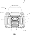
Fig. 2 depicts a side view of the lighting device, according to an embodiment of the invention; -
Fig. 3 depicts partially-exposed perspective view of the lighting device, according to an embodiment; -
Fig. 4 depicts an exemplary block circuit diagram of the lighting device, according to an embodiment; -
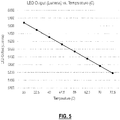
Fig. 5 depicts an exemplary graph representing a temperature v. LED output diagram, according to an embodiment; -
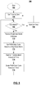
Fig. 6 is an exemplary flow diagram for controlling power of the lighting device, according to an embodiment; -
Fig. 7 depicts an exemplary graph representing a PWM counts v. battery pack voltage diagram, according to an embodiment; -
Fig. 8 is an exemplary flow diagram for controlling power of the lighting device, according to an alternative embodiment; - Corresponding reference numerals indicate corresponding parts throughout the several views of the drawings.
- The following description illustrates the claimed invention by way of example and not by way of limitation. The description clearly enables one skilled in the art to make and use the disclosure, describes several embodiments, adaptations, variations, alternatives, and uses of the disclosure, including what is presently believed to be the best mode of carrying out the claimed invention. Additionally, it is to be understood that the disclosure is not limited in its application to the details of construction and the arrangements of components set forth in the following description or illustrated in the drawings. The disclosure is capable of other embodiments and of being practiced or being carried out in various ways. Also, it is to be understood that the phraseology and terminology used herein is for the purpose of description and should not be regarded as limiting.
- As shown in
Figs. 1-3 , according to an embodiment of the invention, aportable lighting device 100 is described herein. In an embodiment, the lighting device includes amain body 110 and ahead portion 120 accommodating at least one Light Emitting Diode (LED) 122. - In an embodiment, the
main body 110 includes a substantially square-shaped orcircular base 112 and a cubical orcylindrical body 114. Fourvertical side handles 116 are disposed around themain body 110. Themain body 116 includes abattery receptacle 118 having a hingeddoor 119 that receives a sliding battery pack (not shown) therein. The main body also includes acontrol interface 130 for receiving control commands from a user. The control interface includes push-buttons control interface 130 also include an 'Eco-Mode'button 134, as described later in detail. - In an embodiment, the
head portion 120 includes a Chip-on-Board (COB)LED 122 mounted on aheat sink 124. Theheat sink 124 may be disc-shaped or cylindrical, including acentral base portion 125 and outward-projectingfins 126 projecting radially outwardly from thebase portion 125. TheCOB LED 122 is mounted on top of thebase portion 125 to allow theheat sink 124 to dissipate heat away fromLED 122. Adiffuser 128 having a semispherical head is mounted on the heatsink base portion 125 around theLED 122. Alens 129 is mounted on themain body 110 surrounding thehead portion 120 components. In the illustrated example, cut-off views of thediffusor 128 and thelens 129 are shown to expose theheat sink 124 andLED 122. -
Fig. 4 depicts an exemplary block circuit diagram 400 of the lighting device, according to an embodiment. In an embodiment, thelighting device 100 is provided withLED 122, as described above, receiving power from aremoveable battery pack 402 received through thebattery receptacle 118. A solid-state switch 404 is disposed on the electrical path (i.e., us line 406) between thebattery pack 402 and theLED 122. A gate of solid-state switch 404 is driven via agate driver 414 bycontroller 410.Controller 410, in an example, is a programmable device such as a micro-controller, microprocessor, digital signal processor, etc.Controller 410 is powered by avoltage regulator 408 coupled to thebus line 406. The voltage regulator provides thecontroller 410 with a voltage (e.g., 3.2v) suitable for powering thecontroller 410. - In an embodiment,
controller 410 controls the switching operation of theswitch 404 via a pulse-width modulation (PWM) control technique to regulate the amount of electric power being supplied to theLED 122. In an embodiment,controller 410 receives a mode selection (i.e., luminance mode level selected by the user) from thecontrol interface 130 and sets a PWM duty cycle for theswitch 404 accordingly. Table 1 below. In this table, PWM duty cycle is set to a maximum 100% in a high-luminance mode, to 66% in a medium-luminance mode, and to 33% in a low-luminance mode. In an embodiment, a PWM count is further set in proportion to the duty cycle on a 0 to 255 graduation scale, at a 0.4 KHz frequency.TABLE 1 Luminance Mode PWM Duty PWM Count High 100% 255 Medium 66% 170 Low 33% 85 - In an embodiment, a
level shifter 412 is also coupled to thebus line 406 to provide a voltage sense signal to thecontroller 410 corresponding to the voltage of thebus line 406. As described below, in an embodiment, thecontroller 410 may use the voltage sense signal to determine the voltage level of thebattery pack 402. -
Fig. 5 is a diagram illustrating the correlation between temperature and LED output, according to an embodiment. As seen herein, the efficiency of LEDs, defined by the ratios of electrical power (watts) input / output of the LED, improves as the operating temperature of the LED is lowered. The heat sink plays a key role in maintaining the LED temperature. A reduction in drive current can also result in not only a reduction in optical power output of the LED, but also a reduction in operating temperature if the LED is not under active temperature control. As a result, for any given reduction in drive power, the reduction in power output is less than it would be if the LED temperature were held constant. For example, a 20% reduction in drive power may result in an approximately 15% reduction in optical power output. - In an embodiment, this effect is utilized to reduce the drive current for the purpose of preserving battery power, while partially compensating for the reduction in power output with increased efficiency.
- According to an embodiment, 'Eco-mode'
button 134 is provided to provide the user the ability to operate the light in a way to preserve and prolong battery life. When this button is activated, thecontroller 410 adjusts the PWM duty cycle (or PWM counts) as described below in a way to lower luminance output of theLED 122 while preserving battery power in an efficient manner. -
Fig. 6 is anexemplary flow process 600 diagram for controlling power of the lighting device executed by thecontroller 410, according to an embodiment. In this embodiment, in 'Eco-mode,' thecontroller 410 reduces the level of brightness of theLED 122 in accordance with a specified scaler that is based on the prevailing state of charge of thebattery pack 402. - In an embodiment, in executing
flow process 600, which starts atstep 602, thecontroller 410 begins by setting resetting a timer to zero atstep 604. Thecontroller 410 then determines, instep 606, whether to enter 'Eco-mode' based on input from the 'Eco-mode'button 134 of thecontrol interface 130. If not, instep 608, thecontroller 410 waits for a predetermined amount of time repeatssteps - In
step 610,controller 410 receives a brightness mode selection, as selected by the user, from thecontrol interface 130. Instep 612,controller 410 sets the PWM duty cycle (and/or PWM counts) based on brightness mode, as shown in the example provide in Table 1 above. Instep 614,controller 410 also determinesbattery pack 402 voltage. In an embodiment, thecontroller 410 does this based on the voltage sense signal from thelevel shifter 412. Subsequently, instep 616,controller 410 scales the PWM duty cycle (and/or PWM counts) based on the battery voltage.Process 600 then returns to step 608, where thecontroller 410 waits for a predetermined amount of time (e.g., 1 second) before it tests the state of charge of the battery again and repeat this process. - Table 2 depicts an example of the scaling technique utilized by the
controller 410 instep 616. In this example, PWM count is scaled based on a State of Charge (SOC) Scalar value.TABLE 2 Luminance Mode PWM Duty PWM Count High 100% 255 * SOC Scalar Medium 66% 170 * SOC Scalar Low 33% 85 * SOC Scalar - Table 3 is an exemplary table utilized by the
controller 410 to determine the SOC Scalar relative to the battery pack SOC.TABLE 3 Pack V SOC Scalar 19.85-20.8 1.000 19.8 0.983 19.7 0.950 19.6 0.917 19.5 0.883 19.4 0.850 19.3 0.817 19.2 0.783 19.1 0.750 19 0.717 18.9 0.683 15-18.8V 0.650 - In an embodiment, when SOC Scalar is applied to scale the PWM counts (or PWM duty cycle), PWM is naturally decremented over the course of the battery discharge cycle. In this mode, turning the
light device 100 OFF and back ON causes thecontroller 410 to pick up where it left off, i.e., at a PWM level corresponding to the state of charge of thebattery pack 402. -
Fig. 7 depicts a graphical representation of PWM counts v. battery pack voltage (SOC) chart in the high luminance, medium luminance, and low luminance modes of operation in 'Eco-mode,' as described above, according to an embodiment. -
Fig. 8 is an exemplary flow diagram for controlling power of the lighting device executed by the controller, according to an alternative embodiment. In this embodiment, in 'Eco-mode,' thecontroller 410 reduces the level of brightness of theLED 122 in accordance with a specified scaler that is based on the run time of theLED 122 usingbattery pack 402. - In an embodiment, in executing
flow process 700, which starts at step 702, thecontroller 410 begins by setting resetting a timer to zero atstep 704. Thecontroller 410 then determines, instep 706, whether to enter 'Eco-mode' based on input from the 'Eco-mode'button 134 of thecontrol interface 130. If not, instep 708, thecontroller 410 waits for a predetermined amount of time repeatssteps - In
step 710,controller 410 receives a brightness mode selection, as selected by the user, from thecontrol interface 130. Instep 712,controller 410 sets the PWM duty cycle (and/or PWM counts) based on brightness mode, as shown in the example provide in Table 1 above. Instep 714,controller 410 waits for a predetermined amount of time (e.g., 30 seconds). Subsequently, in step 716,controller 410 scales the PWM duty cycle (and/or PWM counts) based on the timer.Process 700 then returns to step 706, where it repeats steps 710-716 again as long as thelight device 100 is being operated in 'Eco-mode', periodically decrementing the PWM count (or PWM duty cycle). - Table 4 is an exemplary table utilized by the
controller 410 to determine a Eco Mode Scalar relative to thelighting device 100 run time.TABLE 4 Elapsed Time (s) ECO Mode Scalar 0-180 1 240 0.98 300 0.96 360 0.94 420 0.92 480 0.9 540 0.88 600 0.86 660 0.84 720 0.82 780 0.8 840 0.78 900 0.76 930-1140 0.75 - In an embodiment, when Eco Scalar is applied to scale the PWM counts (or PWM duty cycle), PWM is naturally decremented over the course of time for the first several minutes (e.g., 15 minutes) after invocation of 'Eco-mode'. Once a scalar of 0.75 is reached, the
controller 410 will continue to operate the light at the same brightness level until either the battery pack is fully discharged or the light is turned OFF. In eco-mode, turning thelight device 100 OFF and back ON causes thecontroller 410 to reset the timer and return the PWM scalar back to 1. - The foregoing description of the embodiments has been provided for purposes of illustration and description. It is not intended to be exhaustive or to limit the disclosure. Individual elements or features of a particular embodiment are generally not limited to that particular embodiment, but, where applicable, are interchangeable and can be used in a selected embodiment, even if not specifically shown or described. The same may also be varied in many ways. Such variations are not to be regarded as a departure from the disclosure, and all such modifications are intended to be included within the scope of the disclosure.
- Example embodiments are provided so that this disclosure will be thorough, and will fully convey the scope to those who are skilled in the art. Numerous specific details are set forth such as examples of specific components, devices, and methods, to provide a thorough understanding of embodiments of the present disclosure. It will be apparent to those skilled in the art that specific details need not be employed, that example embodiments may be embodied in many different forms and that neither should be construed to limit the scope of the disclosure. In some example embodiments, well-known processes, well-known device structures, and well-known technologies are not described in detail.
- The terminology used herein is for the purpose of describing particular example embodiments only and is not intended to be limiting. As used herein, the singular forms "a," "an," and "the" may be intended to include the plural forms as well, unless the context clearly indicates otherwise. The terms "comprises," "comprising," "including," and "having," are inclusive and therefore specify the presence of stated features, integers, steps, operations, elements, and/or components, but do not preclude the presence or addition of one or more other features, integers, steps, operations, elements, components, and/or groups thereof. The method steps, processes, and operations described herein are not to be construed as necessarily requiring their performance in the particular order discussed or illustrated, unless specifically identified as an order of performance. It is also to be understood that additional or alternative steps may be employed.
Claims (15)
- A lighting apparatus comprising:a lighting unit arranged to emit light;a switching device disposed between a power source and the lighting unit; anda controller configured to set a drive signal based on a target luminance level of the lighting unit and control a switching operation of the switching device via a drive signal to regulate a supply of electric power from the power source to the lighting unit,wherein the controller is configured to monitor a voltage of the power source and periodically adjust the drive signal based on the voltage of the power source.
- The lighting apparatus of claim 8, wherein the control interface further receives an input from the user indicative of a first mode, wherein the controller periodically adjust the drive signal based on the voltage of the power source, or a second mode, wherein the controller does not adjust the drive signal based on the voltage of the power source.
- The lighting apparatus of claim 1, wherein the controller is configured to scale down the drive signal when the voltage of the power source is less than a first threshold but greater than a second threshold.
- The lighting apparatus of claim 1, wherein, when the lighting apparatus is turned ON, the controller adjusts the drive signal based on the voltage of the power source.
- The lighting apparatus of claim 1, comprising a level shifter disposed between the power source and the controller and configured to provide the controller with a voltage signal indicative of the voltage of the power source.
- A lighting apparatus comprising:a lighting unit arranged to emit light;a switching device disposed between a power source and the lighting unit; anda controller configured to set a drive signal based on a target luminance level of the lighting unit and control a switching operation of the switching device via a drive signal to regulate a supply of electric power from the power source to the lighting unit,wherein the controller is configured to adjust the drive signal periodically to reduce the supply of electric power from the power source to the lighting unit after passage of a first predetermined time until a second predetermined time is reached.
- The lighting apparatus of claim 6, wherein the controller is configured to set a pulse-width modulation (PWM) duty cycle associated with the drive signal based on the target luminance level of the lighting unit and reduce the PWM duty cycle based on a timer that is incremented periodically between the first predetermined time and a second predetermined time.
- The lighting apparatus of either claims 1 or 7, further comprising a control interface configured to receive an input from a user indicative of a selected luminance mode and communicate the selected luminance mode to the controller, the controller setting the drive signal based on the selected luminance mode.
- The lighting apparatus of claim 8, wherein the control interface further receives an input from the user indicative of a first mode, wherein the controller periodically adjusts the drive signal based on the timer between the first predetermined time and the second predetermined time, or a second mode, wherein the controller does not adjust the drive signal based on a timer.
- The lighting apparatus of claim 7, wherein, when the lighting apparatus is turned ON, the controller resets the timer.
- The lighting apparatus of either claim 1 or6, comprising main body and a head portion mounted on the main body, the main body including a battery receptacle for receiving a removable battery pack therein, the head portion including a heat sink,
wherein the lighting unit comprises a chip-on-board (COB) light Emitting Diode (LED) mounted on the heat sink. - A method of controlling a lighting apparatus having a lighting unit arranged to emit light via a controller and a switching device disposed between a power source and the lighting unit, the method comprising:receiving a signal associated with a target luminance level of the lighting unit;setting a drive signal based on the target luminance level;controlling a switching operation of the switching device via the drive signal to regulate supply of electric power from the power supply to the lighting unit;monitoring a voltage of the power supply; andadjusting the drive signal periodically based on the voltage of the power source.
- The lighting apparatus of claim 1 wherein the controller is configured or the method of claim 12, wherein the controlling a switching operation step comprises:
setting a pulse-width modulation (PWM) duty cycle associated with the drive signal based on the target luminance level of the lighting unit, and modifying the PWM duty cycle based on the voltage of the power source. - The method of claim 12, further comprising receiving a luminance mode signal from a control interface of the lighting apparatus, the luminance mode signal being indicative of a selected luminance mode, and setting the drive signal based on the selected luminance mode.
- The method of claim 12, wherein the adjusting step comprises scaling down the drive signal when the voltage of the power source is less than a first threshold but greater than a second threshold.
Applications Claiming Priority (1)
| Application Number | Priority Date | Filing Date | Title |
|---|---|---|---|
| US15/981,130 US10412805B1 (en) | 2018-05-16 | 2018-05-16 | Control method and apparatus for extending runtime on a portable lighting device |
Publications (1)
| Publication Number | Publication Date |
|---|---|
| EP3570641A1 true EP3570641A1 (en) | 2019-11-20 |
Family
ID=65685257
Family Applications (1)
| Application Number | Title | Priority Date | Filing Date |
|---|---|---|---|
| EP19160535.1A Withdrawn EP3570641A1 (en) | 2018-05-16 | 2019-03-04 | Control method and apparatus for extending runtime on a portable lighting device |
Country Status (2)
| Country | Link |
|---|---|
| US (1) | US10412805B1 (en) |
| EP (1) | EP3570641A1 (en) |
Cited By (1)
| Publication number | Priority date | Publication date | Assignee | Title |
|---|---|---|---|---|
| EP4409637A4 (en) * | 2021-10-01 | 2026-01-14 | Liquid Lumens Llc | INTEGRATED UNDERWATER LED LIGHT ARRAY |
Families Citing this family (3)
| Publication number | Priority date | Publication date | Assignee | Title |
|---|---|---|---|---|
| EP4268545A4 (en) * | 2020-12-22 | 2024-10-23 | Milwaukee Electric Tool Corporation | LIGHTING DEVICE WITH STATE OF CHARGE-BASED CONTROL |
| WO2022155589A1 (en) | 2021-01-18 | 2022-07-21 | Milwaukee Electric Tool Corporation | Lighting apparatus having ultra-low mode |
| US11959616B2 (en) * | 2021-10-15 | 2024-04-16 | Briggs & Stratton, Llc | Battery powered light tower |
Citations (6)
| Publication number | Priority date | Publication date | Assignee | Title |
|---|---|---|---|---|
| US20060043911A1 (en) * | 2004-08-31 | 2006-03-02 | Jianwen Shao | Method and circuit for driving a low voltage light emitting diode |
| US20110074431A1 (en) * | 2009-12-29 | 2011-03-31 | Guoxing Li | Circuits and methods for measuring cell voltages in battery packs |
| US20130113388A1 (en) * | 2011-11-03 | 2013-05-09 | Echostar Technologies L.L.C. | Duty Cycle Adjustment of Remote Illumination Source to Maintain Illumination Output |
| US20160348879A1 (en) | 2015-05-29 | 2016-12-01 | Black & Decker Inc. | Work Light |
| JP2017073280A (en) * | 2015-10-07 | 2017-04-13 | 株式会社デンソー | Illumination device |
| US20170135172A1 (en) * | 2015-11-11 | 2017-05-11 | Luminara Worldwide, Llc | Systems and Methods for Reducing Energy Requirements of an Electric Light |
Family Cites Families (25)
| Publication number | Priority date | Publication date | Assignee | Title |
|---|---|---|---|---|
| US7604370B2 (en) | 2005-02-08 | 2009-10-20 | Versalite Associates | Versatile lighting device |
| US7651240B2 (en) | 2006-01-10 | 2010-01-26 | Bayco Products. Ltd. | Combination task lamp and flash light |
| KR100760943B1 (en) | 2006-01-25 | 2007-09-21 | 엘지.필립스 엘시디 주식회사 | Driving device and driving method of mobile display device |
| JP4889398B2 (en) | 2006-07-27 | 2012-03-07 | 株式会社リコー | Constant voltage power circuit |
| US8253352B2 (en) * | 2008-08-05 | 2012-08-28 | O2Micro, Inc. | Circuits and methods for powering light sources |
| US9478108B2 (en) | 2008-11-10 | 2016-10-25 | Archangel Device Llc | Multi-directional, multi-functional, wearable safety lighting apparatus |
| US8760085B2 (en) | 2009-01-14 | 2014-06-24 | Mag Instrument, Inc. | Multi-mode portable lighting device |
| US8492988B2 (en) | 2009-10-07 | 2013-07-23 | Lutron Electronics Co., Inc. | Configurable load control device for light-emitting diode light sources |
| DE102010003834A1 (en) | 2010-04-09 | 2011-10-13 | Tridonic Gmbh & Co. Kg | Operating device for lighting means for determining an energy or power consumption and method for detecting desselbigen |
| CN102014543B (en) * | 2010-07-02 | 2011-12-28 | 凹凸电子(武汉)有限公司 | Drive circuit and method of drive light source and controller |
| TWI440398B (en) | 2010-09-13 | 2014-06-01 | Richtek Technology Corp | Direct current light emitting device control circuit with dimming function and method thereof |
| US10321541B2 (en) * | 2011-03-11 | 2019-06-11 | Ilumi Solutions, Inc. | LED lighting device |
| US8680787B2 (en) | 2011-03-15 | 2014-03-25 | Lutron Electronics Co., Inc. | Load control device for a light-emitting diode light source |
| FR2987544B1 (en) | 2012-02-29 | 2014-03-07 | Pellenc Sa | INTELLIGENT PORTABLE LIGHTING DEVICE |
| JP2013191304A (en) | 2012-03-12 | 2013-09-26 | Panasonic Corp | Lighting apparatus |
| US9408268B2 (en) * | 2012-06-19 | 2016-08-02 | Wireless Environment, Llc | Group management of a wireless power outage lighting system |
| US8803445B2 (en) * | 2012-09-07 | 2014-08-12 | Infineon Technologies Austria Ag | Circuit and method for driving LEDs |
| US20140253306A1 (en) * | 2013-03-06 | 2014-09-11 | Ford Global Technologies, Llc | Electric Vehicle State of Charge Indicator Integrated With Exterior Lamps |
| US9113521B2 (en) | 2013-05-29 | 2015-08-18 | Lutron Electronics Co., Inc. | Load control device for a light-emitting diode light source |
| WO2015173680A1 (en) | 2014-05-14 | 2015-11-19 | Koninklijke Philips N.V. | Emergency lighting driver with programmable output power |
| EP3604894B1 (en) | 2015-02-04 | 2025-04-09 | Milwaukee Electric Tool Corporation | Light |
| DE102015113065A1 (en) | 2015-08-07 | 2017-02-09 | Nimbus Group Gmbh | Luminaire arrangement and method for its operation |
| ES2844628T3 (en) | 2015-10-30 | 2021-07-22 | Milwaukee Electric Tool Corp | Remote control, configuration and monitoring of lights |
| US10251225B2 (en) | 2015-12-28 | 2019-04-02 | Eaton Intelligent Power Limited | Multi-mode power supply for an LED illumination device |
| WO2017210126A1 (en) | 2016-06-03 | 2017-12-07 | Red Dirt Innovations, Llc | Lighted ladder |
-
2018
- 2018-05-16 US US15/981,130 patent/US10412805B1/en active Active
-
2019
- 2019-03-04 EP EP19160535.1A patent/EP3570641A1/en not_active Withdrawn
Patent Citations (6)
| Publication number | Priority date | Publication date | Assignee | Title |
|---|---|---|---|---|
| US20060043911A1 (en) * | 2004-08-31 | 2006-03-02 | Jianwen Shao | Method and circuit for driving a low voltage light emitting diode |
| US20110074431A1 (en) * | 2009-12-29 | 2011-03-31 | Guoxing Li | Circuits and methods for measuring cell voltages in battery packs |
| US20130113388A1 (en) * | 2011-11-03 | 2013-05-09 | Echostar Technologies L.L.C. | Duty Cycle Adjustment of Remote Illumination Source to Maintain Illumination Output |
| US20160348879A1 (en) | 2015-05-29 | 2016-12-01 | Black & Decker Inc. | Work Light |
| JP2017073280A (en) * | 2015-10-07 | 2017-04-13 | 株式会社デンソー | Illumination device |
| US20170135172A1 (en) * | 2015-11-11 | 2017-05-11 | Luminara Worldwide, Llc | Systems and Methods for Reducing Energy Requirements of an Electric Light |
Cited By (1)
| Publication number | Priority date | Publication date | Assignee | Title |
|---|---|---|---|---|
| EP4409637A4 (en) * | 2021-10-01 | 2026-01-14 | Liquid Lumens Llc | INTEGRATED UNDERWATER LED LIGHT ARRAY |
Also Published As
| Publication number | Publication date |
|---|---|
| US10412805B1 (en) | 2019-09-10 |
Similar Documents
| Publication | Publication Date | Title |
|---|---|---|
| US10412805B1 (en) | Control method and apparatus for extending runtime on a portable lighting device | |
| US11035556B2 (en) | Portable lighting device | |
| US6987366B2 (en) | Step down circuit for an LED flashlight | |
| US7649323B1 (en) | Rechargeable light-emitting diode driver circuit | |
| CN1921726A (en) | Touch sensor and location indicator circuits | |
| US12588117B2 (en) | Portable lighting device | |
| CN103547006B (en) | The ligthing paraphernalia of light-emitting component lamp device and this light-emitting component lamp device of use | |
| WO2004112225A3 (en) | High efficiency off-line linear power supply | |
| EP2579422A3 (en) | Circuit and method fo operation for an electrical power supply | |
| CN114503786B (en) | Portable lighting device with ramp down capability | |
| US20080074869A1 (en) | Lighting apparatus | |
| US6307328B1 (en) | Multipurpose flashlight | |
| US7436125B2 (en) | Light emitting diode drive circuit | |
| EP1465319A3 (en) | Uninterruptible power supply device with circuit for degradation judgment of storage battery | |
| JP2008261660A5 (en) | ||
| US20120136493A1 (en) | Battery Pack Control Circuit for Handheld Battery Operated Device | |
| US11212892B1 (en) | Variable frequency PWM LED control circuit and method | |
| CN107426857B (en) | Lighting device and lighting fixture | |
| JP7511143B2 (en) | Lighting device | |
| JP2009177887A (en) | Power supply for vehicle | |
| JP2007108192A (en) | Auxiliary power supply for high current | |
| CN111491417A (en) | Microwave control dimming circuit and lamp | |
| US20170245335A1 (en) | Light emitting diode driver regulated to consume constant battery current input | |
| KR100715430B1 (en) | Emergency light using light emitting diode | |
| KR100671830B1 (en) | Microwave night light control device and method |
Legal Events
| Date | Code | Title | Description |
|---|---|---|---|
| PUAI | Public reference made under article 153(3) epc to a published international application that has entered the european phase |
Free format text: ORIGINAL CODE: 0009012 |
|
| STAA | Information on the status of an ep patent application or granted ep patent |
Free format text: STATUS: THE APPLICATION HAS BEEN PUBLISHED |
|
| AK | Designated contracting states |
Kind code of ref document: A1 Designated state(s): AL AT BE BG CH CY CZ DE DK EE ES FI FR GB GR HR HU IE IS IT LI LT LU LV MC MK MT NL NO PL PT RO RS SE SI SK SM TR |
|
| AX | Request for extension of the european patent |
Extension state: BA ME |
|
| STAA | Information on the status of an ep patent application or granted ep patent |
Free format text: STATUS: REQUEST FOR EXAMINATION WAS MADE |
|
| 17P | Request for examination filed |
Effective date: 20200325 |
|
| RBV | Designated contracting states (corrected) |
Designated state(s): AL AT BE BG CH CY CZ DE DK EE ES FI FR GB GR HR HU IE IS IT LI LT LU LV MC MK MT NL NO PL PT RO RS SE SI SK SM TR |
|
| STAA | Information on the status of an ep patent application or granted ep patent |
Free format text: STATUS: THE APPLICATION IS DEEMED TO BE WITHDRAWN |
|
| 18D | Application deemed to be withdrawn |
Effective date: 20200603 |