EP3570588A1 - Core resource distribution - Google Patents
Core resource distribution Download PDFInfo
- Publication number
- EP3570588A1 EP3570588A1 EP18173251.2A EP18173251A EP3570588A1 EP 3570588 A1 EP3570588 A1 EP 3570588A1 EP 18173251 A EP18173251 A EP 18173251A EP 3570588 A1 EP3570588 A1 EP 3570588A1
- Authority
- EP
- European Patent Office
- Prior art keywords
- network
- core
- user device
- target
- connection
- Prior art date
- Legal status (The legal status is an assumption and is not a legal conclusion. Google has not performed a legal analysis and makes no representation as to the accuracy of the status listed.)
- Granted
Links
Images




Classifications
-
- H—ELECTRICITY
- H04—ELECTRIC COMMUNICATION TECHNIQUE
- H04W—WIRELESS COMMUNICATION NETWORKS
- H04W28/00—Network traffic management; Network resource management
- H04W28/02—Traffic management, e.g. flow control or congestion control
- H04W28/08—Load balancing or load distribution
- H04W28/086—Load balancing or load distribution among access entities
- H04W28/0861—Load balancing or load distribution among access entities between base stations
- H04W28/0865—Load balancing or load distribution among access entities between base stations of different Radio Access Technologies [RATs], e.g. LTE® or Wi-Fi®
-
- H—ELECTRICITY
- H04—ELECTRIC COMMUNICATION TECHNIQUE
- H04W—WIRELESS COMMUNICATION NETWORKS
- H04W48/00—Access restriction; Network selection; Access point selection
- H04W48/18—Selecting a network or a communication service
-
- H—ELECTRICITY
- H04—ELECTRIC COMMUNICATION TECHNIQUE
- H04W—WIRELESS COMMUNICATION NETWORKS
- H04W60/00—Affiliation to network, e.g. registration; Terminating affiliation with the network, e.g. de-registration
- H04W60/04—Affiliation to network, e.g. registration; Terminating affiliation with the network, e.g. de-registration using triggered events
-
- H—ELECTRICITY
- H04—ELECTRIC COMMUNICATION TECHNIQUE
- H04W—WIRELESS COMMUNICATION NETWORKS
- H04W60/00—Affiliation to network, e.g. registration; Terminating affiliation with the network, e.g. de-registration
- H04W60/06—De-registration or detaching
-
- H—ELECTRICITY
- H04—ELECTRIC COMMUNICATION TECHNIQUE
- H04W—WIRELESS COMMUNICATION NETWORKS
- H04W76/00—Connection management
- H04W76/10—Connection setup
- H04W76/15—Setup of multiple wireless link connections
- H04W76/16—Involving different core network technologies, e.g. a packet-switched [PS] bearer in combination with a circuit-switched [CS] bearer
Definitions
- Various embodiments relate generally to communications with a radio access network.
- a network device comprising a receiver configured to receive a connection request from a user device; a determiner configured to determine a compatibility of the user device with a target core network, and, in the case that the user device is compatible with the target core network, to generate an instruction for the user device to connect to the target core network.
- any phrases explicitly invoking the aforementioned words expressly refers more than one of the said objects.
- the terms “proper subset”, “reduced subset”, and “lesser subset” refer to a subset of a set that is not equal to the set, i.e. a subset of a set that contains less elements than the set.
- a “circuit” as user herein is understood as any kind of logic-implementing entity, which may include special-purpose hardware or a processor executing software.
- a circuit may thus be an analog circuit, digital circuit, mixed-signal circuit, logic circuit, processor, microprocessor, Central Processing Unit (“CPU”), Graphics Processing Unit (“GPU”), Digital Signal Processor (“DSP”), Field Programmable Gate Array (“FPGA”), integrated circuit, Application Specific Integrated Circuit (“ASIC”), etc., or any combination thereof.
- circuit Any other kind of implementation of the respective functions, which will be described below in further detail, may also be understood as a "circuit.” It is understood that any two (or more) of the circuits detailed herein may be realized as a single circuit with substantially equivalent functionality, and conversely that any single circuit detailed herein may be realized as two (or more) separate circuits with substantially equivalent functionality. Additionally, references to a "circuit" may refer to two or more circuits that collectively form a single circuit.
- memory may be understood as a non-transitory computer-readable medium in which data or information can be stored for retrieval. References to "memory” included herein may thus be understood as referring to volatile or non-volatile memory, including random access memory (“RAM”), read-only memory (“ROM”), flash memory, solid-state storage, magnetic tape, hard disk drive, optical drive, etc., or any combination thereof. Furthermore, it is appreciated that registers, shift registers, processor registers, data buffers, etc., are also embraced herein by the term memory.
- a single component referred to as "memory” or “a memory” may be composed of more than one different type of memory, and thus may refer to a collective component comprising one or more types of memory. It is readily understood that any single memory component may be separated into multiple collectively equivalent memory components, and vice versa. Furthermore, while memory may be depicted as separate from one or more other components (such as in the drawings), it is understood that memory may be integrated within another component, such as on a common integrated chip.
- base station used in reference to an access point of a mobile communication network may be understood as a macro base station, micro base station, Node B, evolved NodeB (“eNb”), Home eNodeB, Remote Radio Head (“RRH”), relay point, etc., and may include base stations implemented with conventional base station architectures (e.g. distributed, "all-in-one", etc.) and base stations implemented with centralized base stations architectures (e.g. Cloud Radio Access Network (“Cloud-RAN”) or Virtual RAN (“vRAN”)).
- Cloud-RAN Cloud Radio Access Network
- vRAN Virtual RAN
- a cell may be a set of geographically co-located antennas that correspond to a particular sectorization of a base station.
- a base station may thus serve one or more cells (or sectors), where each cell is characterized by a distinct communication channel.
- the term "cell" may be utilized to refer to any of a macrocell, microcell, femtocell, picocell, etc.
- radio communication technologies may be classified as one of a Short-Range radio communication technology, Metropolitan Area System radio communication technology, or Cellular Wide Area radio communication technology.
- Short Range radio communication technologies include Bluetooth, WLAN (e.g. according to any IEEE 802.11 standard), and other similar radio communication technologies.
- Metropolitan Area System radio communication technologies include Worldwide Interoperability for Microwave Access (“WiMax”) (e.g. according to an IEEE 802.16 radio communication standard, e.g. WiMax fixed or WiMax mobile) and other similar radio communication technologies.
- WiMax Worldwide Interoperability for Microwave Access
- Cellular Wide Area radio communication technologies include GSM, UMTS, LTE, LTE-Advanced (“LTE-A”), New Radio (NR), CDMA, WCDMA, LTE-A, General Packet Radio Service (“GPRS”), Enhanced Data Rates for GSM Evolution (“EDGE”), High Speed Packet Access (“HSPA”), HSPA Plus (“HSPA+”), and other similar radio communication technologies.
- Cellular Wide Area radio communication technologies also include "small cells” of such technologies, such as microcells, femtocells, and picocells.
- Cellular Wide Area radio communication technologies may be generally referred to herein as "cellular” communication technologies. It is understood that exemplary scenarios detailed herein are demonstrative in nature, and accordingly may be similarly applied to various other mobile communication technologies, both existing and not yet formulated, particularly in cases where such mobile communication technologies share similar features as disclosed regarding the following examples.
- network as utilized herein, e.g. in reference to a communication network such as a mobile communication network, encompasses both an access section of a network (e.g. a radio access network ("RAN") section) and a core section of a network (e.g. a core network section).
- RAN radio access network
- core network section e.g. a core network section.
- radio idle mode or “radio idle state” used herein in reference to a mobile terminal refers to a radio control state in which the mobile terminal is not allocated at least one dedicated communication channel of a mobile communication network.
- radio connected mode or “radio connected state” used in reference to a mobile terminal refers to a radio control state in which the mobile terminal is allocated at least one dedicated uplink communication channel of a mobile communication network.
- the term “transmit” encompasses both direct (point-to-point) and indirect transmission (via one or more intermediary points).
- the term “receive” encompasses both direct and indirect reception.
- the term “communicate” encompasses one or both of transmitting and receiving, i.e. unidirectional or bidirectional communication in one or both of the incoming and outgoing directions.
- radio access technologies As radio access technologies are developed, multiple radio access technologies may be simultaneously available to a user device. When a new radio access technology is developed, and a prior radio access technology has not yet reached a state of obsolescence, a user device may be configured to operate with both radio access technologies. Moreover, a radio access network may find it desirable to offer its consumers access to multiple radio access technologies. As such, it is common for multiple radio access technologies to be available to a user device connected to a single radio access network.
- a user device may be configured to operate on an 4G network, a 5G network, or both.
- a user device connected to a radio access network may be linked to either an 4G core or a 5G core.
- Networks providing multiple core networks may require periodic load-balancing or may keep specific user devices (e.g. smartphone device) connected to 5G while moving other devices (e.g. IoT device) to 4G, to better distribute user demands across the available resources. That is, where both a 4G core and a 5G core are available, a disproportionate number of user devices may be connected to one core compared to the other. Similarly, a disproportionate number of resources from one core may be required by the connected devices. Where this occurs, it may be desirable to better distribute the user devices or demands upon the core through load-balancing.
- specific user devices e.g. smartphone device
- IoT device e.g. IoT device
- TAU Tracking Area Update
- An RRC connection release command is transmitted to the user device, with said command including a release cause of "loadBalancingTAURequired". This notifies the user device to perform a TAU following the RRC release.
- the RAN selects a new Mobility Management Entity ("MME") following the TAU.
- MME Mobility Management Entity
- the MME initiates the RRC connection release with the cause "load-balancing TAU required.”
- the eNodeB initiates and RRC connection release with the cause "core resource distribution TAU required.”
- the RRC release triggers a TAU in the user device, without an MME code in the RRC.
- the eNodeB selects a new MME after receiving the TAU.
- the "load-balancing TAU required" command can cause a new MME to be selected, it cannot necessarily be used to change the system. That is, a different system may not necessarily be selected as a result of the TAU procedure unless additional steps are taken.
- a second known method for load-balancing between 4G and 5G involves disabling the N1 mode.
- a command according to 3 rd Generation Partnership Project (“3GPP") Technical Specification 24.501, Clause 4.9 is transmitted by the user device, said command requiring the disablement of N1 mode radio capability.
- the user device operating in a single-registration mode disables the N1 mode radio capability and sets the N1 mode bit to "N1 mode not supported" in the user device network capability information element (described in greater detail in 3GPP Technical Specification 24.301) of the attached request message and the tracking area update request message in the Evolved Packet Core.
- the user device's non-access stratum layer indicates to the access stratum layer or layers the disablement of the N1 mode.
- the N1 mode corresponds to the user device's ability to operate within 5G, and therefore disabling the N1 mode prevents further 5G operation. Disabling the N1 mode is therefore effective in shifting the load from a 4G network to a 5G network. However, using this method, the N1 node is not enabled until the user device restarts or until Public Land Mobile Network (“PLMN”) selection, which may be undesirable. Of note, disabling the N1 mode reduces the ease with which the user device may later be redistributed from 4G to 5G.
- PLMN Public Land Mobile Network
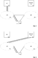
- FIG. 1 shows a user device connected to a radio access technology comprising a 4G/EPC network and a 5GC network.
- the user device 102 is connected to a Radio Access Network operating a given RAT 104.
- the RAT 104 may be any RAT, without limitation, including but not limited to an LTE RAT or to an NR RAT.
- the RAT may have access to a first network 106 and a second network 110.
- the first network may be a 4G network, said network connection being established through a core such as an Evolved Packet Core 106.
- the second network may be a 5GC network, said network connection being established through a 5G core 110.
- the first network may further comprise a Mobility Management Entity ("MME”) 108, which may, inter alia, perform various paging and signaling control functions within the network.
- MME Mobility Management Entity
- the second network may further comprise an access and mobility management function ("AMF") unit 112, which may include various mobility management capabilities, such as UE-based authentication, authorization, mobility management, etc.
- AMF access and mobility management function
- first network and second network are provided herein for clarity and ease of reference but are by no means limited to this order; that is, the RAT 104 may be configured to connect with a first network and a second network, whereby the first network is a 5G network and the second network is a 4G network.
- FIG. 2 shows a user device connected to a radio access technology, with an active connection to a 4G/EPC network.
- the user device 202 is connected to a RAT (which is in this case an LTE RAT 204), which itself has the possibility of establishing a connection with a 4G network (shown as EPC) 208 or a 5G network (shown as NextGenCore) 210.
- EPC 4G network
- NextGenCore NextGenCore
- the user device 202 is connected to the 4G/EPC network 208 through the LTE RAT 204, as indicated by the dashed line.
- the user device 202 is connected to and serviced by the 4G network 208, along with any other user devices currently connected to or serviced by the 4G network 208.
- the user device 202 can be switched from the 4G network 208 to the 5G network 210. This may be performed while maintaining a direct connection to the LTE network 204.
- FIG. 3 shows a user device connected to a radio access technology, with an active connection to a 5G/NextGen Core network 310.
- the user device 302 is connected to the LTE RAT 304, which is connected to the 5G/NextGen core 310, as demonstrated by the dashed lines.
- the user device 302 is connected to the LTE network 304, which provides services to and from the 5G network 310.
- the 5G network 310 services the user device 302, along with any other devices that are currently connected to the 5G network 310. For instance, for core resource distribution purposes, it may be necessary to offload one or more user devices from the 5G network 310 to the 4G network 308.
- FIG. 4 shows a procedure for core resource distribution, according to a first aspect of the disclosure.
- communication is performed among a variety of communication elements including a 5G-enabled user device 402, a radio access network (“RAN") 404, an access and mobility function (“AMF") element 406, a mobility management entity (“MME”) 408, and a Home Subscriber Server (“HSS”) / Unified Data Management (“UDM”) element 410.
- RAN radio access network
- AMF access and mobility function
- MME mobility management entity
- HSS Home Subscriber Server
- UDM Unified Data Management
- the MME 408 and/or AMF 406 decides to apply load-balancing 412.
- the AMF 406 waits for the next mobility registration.
- the UE then sends a registration request 414.
- the AMF accepts the registration request 418, the response also carrying the RAT/Frequency Selection Priority ("RFSP") index to the RAN 420.
- Said cause may be a new cause which may not be currently found within an applicable published standard; or it may be possible to re-use any identified existing cause for this purpose.
- the RAN releases the RRC connection with cause "inter-system load-balancing required.” 424.
- Said cause may also be a new cause which may not currently be found within an applicable published standard or can be possible to re-use any identified existing cause for this purpose.
- the RRC layer in the user device notifies the non-access spectrum layer regarding the cause.
- the non-access spectrum layer initiates a tracking area update in the target system (such as the EPS) with a mapped Globally Unique Temporary Identification ("GUTI").
- the non-access spectrum layer indicates to the RRC layer not to include the mapped Globally Unique MME Identifier in the RRC connection request. 426.
- the RAN selects a new MME and sends the tracking area update to the MME 428.
- the MME retrieves the context from the old AMF (based on the mapped GUTI). 430. Said context may include the RAT/Frequency Selection Priority index.
- the MME updates the location to the Home Subscriber Service/Unified Data Management 432.
- the Home Subscriber Service/Unified Data Management cancels the registration in the AMF 434.
- the MME accepts the tracking area update 436, said response also carrying the RAT/Frequency Selection Priority index to the RAN.
- the RAN sets the idle mode camping priorities and handover restrictions accordingly such that the user device stays within the EPC, and the RAN does not initiate an inter-system handover back to 5G.
- the RAT/Frequency Selection Priority index is set to ensure that the user device stays in the correct RAT while in the idle mode, and that the RAN does not perform a handover back to the old system.
- the AMF/MME retrieves the RAT/Frequency Selection Priority index from the UDM/HSS.
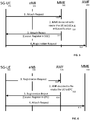
- FIG. 5 shows a procedure for core resource distribution to a 5G network, according to a second aspect of the disclosure.
- This procedure includes communication between a 5G enabled user device 502, an eNB 504, the MME 506, and an AMF 508.
- the 5G enabled user device 502 sends an attachment request 510 to the MME 506.
- the MME decides to reroute the user device to a 5G network pursuant to load-balancing 510.
- the MME sends an attachment rejection 512 to the 5G enabled user device 502, with the cause for the rejection being a command to register in the 5G network.
- the 5G enabled user device 502 then sends a registration request 514 to the AMF 508.
- the MME rejects the user device's attachment request.
- the causes included which indicates that the user device must perform a registration with the 5G core.
- the user device performs the registration procedure with the 5G core along with a 5G parameter. This procedure may require definition of a new cause code which is currently not contained within the published standards.
- FIG. 6 shows a procedure for core resource distribution from a 5G network, according to a third aspect of the disclosure.
- This procedure involves communication between a 5G enabled user device 602, and eNB 604, the AMF 606, and an MMR 608.
- the 5G enabled user device 602 sends a registration request 610 to the AMF 606.
- the AMF decides to reroute the user device to the EPC 612.
- the AMF 606 sends a registration rejection 614 to the 5G enabled user device 602, with the rejection because being the need to register in the EPC.
- the 5G enabled user device 602 then sends an attachment request 616 to the MME 608.
- the AMF rejects the user device's registration request. Along with the rejection is included to cause, which indicates that the user device must perform and attach procedure in the EPC. After such indication, the user device performs the attached procedure with the EPC along with a 4G parameter. This procedure may require definition of a new cause code which is currently not contained within the published standards.
- FIG. 7 shows a load-balancing procedure according to a fourth aspect of the disclosure.
- communication occurs between a 5G enabled user device 702, a RAN 704, and an MME/AMF 706.
- the MME/AMF 706 decides to apply load-balancing to an opposite core 708. That is, the 5G core redistributes a user device to the 4G core, or the 4G core redistributes a user device to the 5G core.
- the MME/AMF 706 applies load-balancing with the 5G/EPS based on one or more categories such as, but not limited to user device group ID, connection slice or sliced types, a dedicated core network ID, one or more specific user devices, or otherwise 710.
- a 5G enabled user device sends an attachment request 712 to the RAN 704, and the RAN 704 response within RRC rejection 714 stating that the EPS is not available and 5G is available, or vice versa.
- the 5G enabled user device 702 then sends a registration request to the alternative network, in this case the MME/AMF 716.
- FIG 8 shows a wireless network system according to one aspect of the disclosure, said system comprising a radio access network 802, configured to receive from a user device a connection request to connect to a first network core 804; the first network core 804, configured to receive from the radio access network the connection request from the user device 806; to determine a compatibility of the user device with a second network core 808; and in the case the user device is compatible with the second network core 808, to generate an instruction for the user device 806 to connect to the second network core 808; the second network core 808, configured to obtain from the first network core 804 a network priority value corresponding to the user device 806, update the network priority value to maintain a connection between the user device 806 and the second network core 808, and transmit the updated network priority value to the radio access network 802.
- a radio access network 802 configured to receive from a user device a connection request to connect to a first network core 804
- the first network core 804 configured to receive from the radio access network the connection request from the user device 806; to determine
- FIG: 9 shows a network device 900 according to one aspect of the disclosure, said network device comprising a receiver 902 configured to receive a connection request from a user device; a determiner 904 configured to determine a compatibility of the user device with a target core network, and, in the case that the user device is compatible with the target core network, to generate an instruction for the user device to connect to the target core network.
- FIG. 10 is disclosed a method of core resource distribution comprising receiving a connection request from a user device 1002; determining a compatibility of the user device with a target core network 1004, and generating, in the case that the user device is compatible with the target core network, an instruction for the user device to connect to the target core network 1006.
- FIG. 11 a method of core resource distribution comprising transmitting to a network device a connection request for connection to a source network core; transmitting a user device compatibility with a target network core 1102; receiving an instruction to connect to the target network core 1104; and transmitting to the network device a connection request for connection to the target network core pursuant to the instruction 1106.
- load-balancing may be performed proactively.
- the MME or AMF will notify the RAN to apply a load-balancing with either the EPS (4G) or the 5G core.
- the RAN notifies the user device that the requested core network (in this case the EPC) is not available, but that another core network (such as, in this example, 5G) is available for service. This may include in RRC rejection with a new cause value.
- the user device After receiving this, the user device performs a registration request with the other network (in this case, the 5G network). This may include a Globally Unique Temporary Identification ("GUTI”) translation is the GUTI is already assigned to the user device.
- GUI Globally Unique Temporary Identification
- this procedure may be performed on a specific user device, or alternatively, on all user devices belonging to a specific group.
- groups may include, but are not limited to devices on a specific Dedicated Core Network, in a network slice, or any other user device grouping.
- EPC transfers this may require a new parameter within the S1 configuration or a new message type in S1-AP.
- this may utilize the existing AMF redirection procedure (such as for AMF load rebalancing) with a new parameter.
- a given core knows when a connected user device supports a second core. More concretely, an MME will generally know that a user device also supports a 5G core, and an AMF (for 5G) notes that the user device supports the EPC (for 4G). For example, the user device may notify the MME in the attached request that it supports the N1 mode (5G), and the user device may notify the AMF in the registration request that it supports the S-1 mode (4G). This procedure may be triggered, such as via Operation & Maintenance and Unified Data Management/Home Subscriber Service procedures. If the user devices in idle mode, the network may be able to wait until the user device becomes connected before it sends an instruction to the user device.
- 5G N1 mode
- 4G S-1 mode
- the first network core may be either of a 4 th Generation Wireless System (“4G”) core or 5 th Generation Wireless System (“5G”) core
- the second network core may be the other of either the 4G or the 5G.
- 4G 4 th Generation Wireless System
- 5G 5 th Generation Wireless System
- the second network core may be the other of either the 4G or the 5G.
- 4G 4 th Generation Wireless System
- 5G 5 th Generation Wireless System
- Such networks may be accessible to a user device through a single RAN, which may facilitate connections to either the 4G or the 5G network.
- a user device may be assigned to either a 4G network or a 5G network based, for example, on compatibility with a given network, or a preference for a specific network. These factors may not take into account network capacity, and therefore it may become necessary or desirable to implement one or more resource distribution mechanisms, such that user device demands may be more appropriately distributed between available network cores.
- the load distribution methods and principles described herein may be directed for clarity purposes to a 4G and 5G network; however, the principles and methods described herein may be applied to other network settings and are not specifically limited to 4G and 5G networks. It is anticipated that the principles and methods described herein may apply to successive networks to the 5G network and/or to legacy networks that predate the 4G network.
- a load distribution procedure is successful, and thereby a user device is caused to discontinue a connection or connection attempts with a first network core, and establish a connection with a second network core
- Continued connection to the second network core may be fostered by modification of a network priority value. It is anticipated that a network priority value may be transmitted during communication between a user device and at least one of the RAN or a network core.
- Said network priority value may comprise one or more network identifiers and a priority for the one or more network identifiers.
- identifier for the 4G network may be listed along with an identifier of the 5G network, and such identifiers may be listed in such a way as to impart priority or preference for connection.
- the network priority value may be a RAT/Frequency Selection Index.
- the network priority value may be modified to either eliminate the first network core or to de-prioritize the first network core, such that the second network core maintains a higher priority. In so doing, the likelihood of reverting to the first network core is reduced.
- the RAN may assist in load-balancing by selecting a second network core in response to a tracking area update. This may occur, for example, when a load-balancing procedure results in a transition of the user device from a 5G network core to a 4G network core.
- the AMF (5G) may release an N2 (5G) connection with the 4G network core and/or the RRC connection, and thereby provide a release cause such as, for example, "inter-system core resource distribution required.”
- N2 (5G) connection with the 4G network core and/or the RRC connection
- the example provided herein may be a new cause, not currently contained within a published specification, but which may be created and/or utilized to carry out load-balancing.
- the proposed text for such a command is merely provided as an example, and the text may be modified as desired.
- the NAS layer of the user device may initiate a tracking area update within the target system with a mapped GUTI.
- the NAS layer may indicate to the RRC layer not to include the mapped GUMMEI in the RRC connection request.
- the RAN receives the tracking area update response and selects a new network core.
- the new network core may be selected based on the absence of the GUMMEI in the RRC connection request and/or knowledge by the RAN of the load distribution procedure.
- a user device may be redirected to a second network core in response to a connection request to a first network core.
- a user device attempting to connect to a 4G core may send an attachment request, which will be rejected within instruction to perform a registration with the 5G core.
- a user device attempting to connect to a 5G core may send a registration request, which may be rejected within instruction to perform an attach procedure in the 4G core.
- rejections may be accompanied by a cause, said cause advising the user device of a load-balancing procedure. Where no cause is defined within the published specifications, or where it is otherwise desired, a new cause code may be defined.
- the load-balancing may be performed reactively or prospectively.
- Reactive performance may be understood to mean load-balancing that is carried out in response to a connection request/attach request. That is, once a decision to perform load-balancing has been made, a user device may be redirected to a second network core in response to a an effort from the user device to connect or attach to a first network core.
- Prospect of load-balancing may be understood to mean load-balancing without necessarily waiting for a connection request/attach request. That is, it may be determined that one or more user devices should be moved from a first network core to a second network core. Said one or more user devices may be identified by a unique user device identifier or by the user device's membership within a group.
- Said groups may include but are not limited to, user device group identification, dynamic circuit network, network slice, or a specific user device. That is, where a group is identified as a group for load-balancing, the user devices that are members of said group may be ascertained, and each user device may then be instructed to register with the second network core according to one of the aspects of the disclosure.
- the load-balancing procedures described herein may be performed while maintaining N1 mode capability.
- a known method of triggering a load-balancing switch from a 5G network to a 4G network is to disable N1 mode compatibility within a user device. Because N1 mode compatibility is necessary for a 5G connection, a disabled N1 mode compatibility may result in the user device being unable to communicate on a 5G network. Where this occurs, the user device will be compelled to connect to a different network core, such as a 4G core. Because of the disadvantages related thereto, it may be desirable to perform load-balancing while maintaining the N1 compatibility. It is anticipated that the methods and procedures described herein may be performed while in one compatibility is maintained.
- the user device may be prompted to transmit one or more updated parameters to the network device. This may be due to an express request by the network device, a rejections of a connection request, or a release of a connection.
- the one or more updated parameters may comprise any one or combination of an EPS update type, NAS key set identifier, a prior GUTI, a GPRS ciphering key sequence number, a prior P-TMSI signature, an additional GUTI, a UE network capability, a last visited registered TAI, a DRX parameter, an EPS bearer context status, a MS network capability, a prior location area identification, one or more supported codecs, one or more device properties, or any combination thereof.
- the one or more updated parameters may be performed via a tracking area update.
- These core resource distribution methods and procedures may be performed by a computer readable medium, that is configured to cause one or more processors to perform any of the actions described herein.
Landscapes
- Engineering & Computer Science (AREA)
- Computer Networks & Wireless Communication (AREA)
- Signal Processing (AREA)
- Computer Security & Cryptography (AREA)
- Mobile Radio Communication Systems (AREA)
Abstract
Description
- Various embodiments relate generally to communications with a radio access network.
- Where multiple network cores are available on a wireless radio access technology network, it may be desirable to distribute core resources by transitioning one or more user devices from a first network core to a second network core. Current methods for performing core resource distribution may be unsuccessful or may have undesirable consequences.
- Herein is disclosed a network device, comprising a receiver configured to receive a connection request from a user device; a determiner configured to determine a compatibility of the user device with a target core network, and, in the case that the user device is compatible with the target core network, to generate an instruction for the user device to connect to the target core network.
- In the drawings, like reference characters generally refer to the same parts throughout the different views. The drawings are not necessarily to scale, emphasis instead generally being placed upon illustrating the principles of the Disclosure. In the following description, various aspects of the Disclosure are described with reference to the following drawings, in which:
-
FIG. 1 shows a user device connect to a radio access technology comprising a 4G/EPC network and a 5G/5GC network; -
FIG. 2 shows a user device connected to a radio access technology, with an active connection to a 4G/EPC network; -
FIG. 3 shows a user device connected to a radio access technology, with an active connection to a 5G/NextGen Core network; -
FIG. 4 shows a procedure for core resource distribution, according to a first aspect of the disclosure; -
FIG. 5 shows a procedure for core resource distribution to a 5G network, according to a second aspect of the disclosure; -
FIG. 6 shows a procedure for core resource distribution from a 5G network, according to a third aspect of the disclosure; -
FIG. 7 shows a procedure for core resource distribution from a 5G network, according to a fourth aspect of the disclosure; -
FIG. 8 shows a configuration of a radio access network and two network cores; -
FIG. 9 shows a configuration of a network device; -
FIG. 10 shows a method of core resource distribution according to one aspect of the disclosure; and -
FIG. 11 shows a method of core resource distribution according to another aspect of the disclosure. - The following detailed description refers to the accompanying drawings that show, by way of illustration, specific details and aspects in which the Disclosure may be practiced.
- The word "exemplary" is used herein to mean "serving as an example, instance, or illustration." Any embodiment or design described herein as "exemplary" is not necessarily to be construed as preferred or advantageous over other embodiments or designs.
- The words "plural" and "multiple" in the description and the claims expressly refer to a quantity greater than one. Accordingly, any phrases explicitly invoking the aforementioned words (e.g. "a plurality of [objects]", "multiple [objects]") referring to a quantity of objects expressly refers more than one of the said objects. The terms "group (of)", "set [of]", "collection (of)", "series (of)", "sequence (of)", "grouping (of)", etc., and the like in the description and in the claims, if any, refer to a quantity equal to or greater than one, i.e. one or more. The terms "proper subset", "reduced subset", and "lesser subset" refer to a subset of a set that is not equal to the set, i.e. a subset of a set that contains less elements than the set.
- A "circuit" as user herein is understood as any kind of logic-implementing entity, which may include special-purpose hardware or a processor executing software. A circuit may thus be an analog circuit, digital circuit, mixed-signal circuit, logic circuit, processor, microprocessor, Central Processing Unit ("CPU"), Graphics Processing Unit ("GPU"), Digital Signal Processor ("DSP"), Field Programmable Gate Array ("FPGA"), integrated circuit, Application Specific Integrated Circuit ("ASIC"), etc., or any combination thereof. Any other kind of implementation of the respective functions, which will be described below in further detail, may also be understood as a "circuit." It is understood that any two (or more) of the circuits detailed herein may be realized as a single circuit with substantially equivalent functionality, and conversely that any single circuit detailed herein may be realized as two (or more) separate circuits with substantially equivalent functionality. Additionally, references to a "circuit" may refer to two or more circuits that collectively form a single circuit.
- As used herein, "memory" may be understood as a non-transitory computer-readable medium in which data or information can be stored for retrieval. References to "memory" included herein may thus be understood as referring to volatile or non-volatile memory, including random access memory ("RAM"), read-only memory ("ROM"), flash memory, solid-state storage, magnetic tape, hard disk drive, optical drive, etc., or any combination thereof. Furthermore, it is appreciated that registers, shift registers, processor registers, data buffers, etc., are also embraced herein by the term memory. It is appreciated that a single component referred to as "memory" or "a memory" may be composed of more than one different type of memory, and thus may refer to a collective component comprising one or more types of memory. It is readily understood that any single memory component may be separated into multiple collectively equivalent memory components, and vice versa. Furthermore, while memory may be depicted as separate from one or more other components (such as in the drawings), it is understood that memory may be integrated within another component, such as on a common integrated chip.
- The term "base station" used in reference to an access point of a mobile communication network may be understood as a macro base station, micro base station, Node B, evolved NodeB ("eNb"), Home eNodeB, Remote Radio Head ("RRH"), relay point, etc., and may include base stations implemented with conventional base station architectures (e.g. distributed, "all-in-one", etc.) and base stations implemented with centralized base stations architectures (e.g. Cloud Radio Access Network ("Cloud-RAN") or Virtual RAN ("vRAN")). As used herein, a "cell" in the context of telecommunications may be understood as a sector served by a base station. Accordingly, a cell may be a set of geographically co-located antennas that correspond to a particular sectorization of a base station. A base station may thus serve one or more cells (or sectors), where each cell is characterized by a distinct communication channel. Furthermore, the term "cell" may be utilized to refer to any of a macrocell, microcell, femtocell, picocell, etc.
- For purposes of this disclosure, radio communication technologies may be classified as one of a Short-Range radio communication technology, Metropolitan Area System radio communication technology, or Cellular Wide Area radio communication technology. Short Range radio communication technologies include Bluetooth, WLAN (e.g. according to any IEEE 802.11 standard), and other similar radio communication technologies. Metropolitan Area System radio communication technologies include Worldwide Interoperability for Microwave Access ("WiMax") (e.g. according to an IEEE 802.16 radio communication standard, e.g. WiMax fixed or WiMax mobile) and other similar radio communication technologies. Cellular Wide Area radio communication technologies include GSM, UMTS, LTE, LTE-Advanced ("LTE-A"), New Radio (NR), CDMA, WCDMA, LTE-A, General Packet Radio Service ("GPRS"), Enhanced Data Rates for GSM Evolution ("EDGE"), High Speed Packet Access ("HSPA"), HSPA Plus ("HSPA+"), and other similar radio communication technologies. Cellular Wide Area radio communication technologies also include "small cells" of such technologies, such as microcells, femtocells, and picocells. Cellular Wide Area radio communication technologies may be generally referred to herein as "cellular" communication technologies. It is understood that exemplary scenarios detailed herein are demonstrative in nature, and accordingly may be similarly applied to various other mobile communication technologies, both existing and not yet formulated, particularly in cases where such mobile communication technologies share similar features as disclosed regarding the following examples.
- The term "network" as utilized herein, e.g. in reference to a communication network such as a mobile communication network, encompasses both an access section of a network (e.g. a radio access network ("RAN") section) and a core section of a network (e.g. a core network section). The term "radio idle mode" or "radio idle state" used herein in reference to a mobile terminal refers to a radio control state in which the mobile terminal is not allocated at least one dedicated communication channel of a mobile communication network. The term "radio connected mode" or "radio connected state" used in reference to a mobile terminal refers to a radio control state in which the mobile terminal is allocated at least one dedicated uplink communication channel of a mobile communication network.
- Unless explicitly specified, the term "transmit" encompasses both direct (point-to-point) and indirect transmission (via one or more intermediary points). Similarly, the term "receive" encompasses both direct and indirect reception. The term "communicate" encompasses one or both of transmitting and receiving, i.e. unidirectional or bidirectional communication in one or both of the incoming and outgoing directions.
- As radio access technologies are developed, multiple radio access technologies may be simultaneously available to a user device. When a new radio access technology is developed, and a prior radio access technology has not yet reached a state of obsolescence, a user device may be configured to operate with both radio access technologies. Moreover, a radio access network may find it desirable to offer its consumers access to multiple radio access technologies. As such, it is common for multiple radio access technologies to be available to a user device connected to a single radio access network.
- As 5G networks become more widely available, it is anticipated that consumers' user devices may be configured to operate on an 4G network, a 5G network, or both. Where a user devices capable of operating on both 4G and 5G, a user device connected to a radio access network may be linked to either an 4G core or a 5G core.
- Networks providing multiple core networks, such as, for example, 4G and 5G, may require periodic load-balancing or may keep specific user devices (e.g. smartphone device) connected to 5G while moving other devices (e.g. IoT device) to 4G, to better distribute user demands across the available resources. That is, where both a 4G core and a 5G core are available, a disproportionate number of user devices may be connected to one core compared to the other. Similarly, a disproportionate number of resources from one core may be required by the connected devices. Where this occurs, it may be desirable to better distribute the user devices or demands upon the core through load-balancing.
- One known method of load-balancing within a 4G core require a Tracking Area Update ("TAU"). An RRC connection release command is transmitted to the user device, with said command including a release cause of "loadBalancingTAURequired". This notifies the user device to perform a TAU following the RRC release. The RAN then selects a new Mobility Management Entity ("MME") following the TAU. Under certain known methods, the MME initiates the RRC connection release with the cause "load-balancing TAU required." The eNodeB initiates and RRC connection release with the cause "core resource distribution TAU required." The RRC release triggers a TAU in the user device, without an MME code in the RRC. The eNodeB then selects a new MME after receiving the TAU. Thus, although the "load-balancing TAU required" command can cause a new MME to be selected, it cannot necessarily be used to change the system. That is, a different system may not necessarily be selected as a result of the TAU procedure unless additional steps are taken.
- A second known method for load-balancing between 4G and 5G involves disabling the N1 mode. Using this method, a command according to 3rd Generation Partnership Project ("3GPP") Technical Specification 24.501, Clause 4.9 is transmitted by the user device, said command requiring the disablement of N1 mode radio capability. The user device operating in a single-registration mode disables the N1 mode radio capability and sets the N1 mode bit to "N1 mode not supported" in the user device network capability information element (described in greater detail in 3GPP Technical Specification 24.301) of the attached request message and the tracking area update request message in the Evolved Packet Core. The user device's non-access stratum layer indicates to the access stratum layer or layers the disablement of the N1 mode. The N1 mode corresponds to the user device's ability to operate within 5G, and therefore disabling the N1 mode prevents further 5G operation. Disabling the N1 mode is therefore effective in shifting the load from a 4G network to a 5G network. However, using this method, the N1 node is not enabled until the user device restarts or until Public Land Mobile Network ("PLMN") selection, which may be undesirable. Of note, disabling the N1 mode reduces the ease with which the user device may later be redistributed from 4G to 5G.
- Where both a 4G core and a 5G core are available to user devices connected to a given RAN, it may be desired to create improved procedures for load distribution. The following figures describe load distribution procedures according to various aspects of the disclosure.
-
FIG. 1 shows a user device connected to a radio access technology comprising a 4G/EPC network and a 5GC network. In this case, theuser device 102 is connected to a Radio Access Network operating a givenRAT 104. TheRAT 104 may be any RAT, without limitation, including but not limited to an LTE RAT or to an NR RAT. The RAT may have access to afirst network 106 and asecond network 110. The first network may be a 4G network, said network connection being established through a core such as an EvolvedPacket Core 106. The second network may be a 5GC network, said network connection being established through a5G core 110. The first network may further comprise a Mobility Management Entity ("MME") 108, which may, inter alia, perform various paging and signaling control functions within the network. The second network may further comprise an access and mobility management function ("AMF")unit 112, which may include various mobility management capabilities, such as UE-based authentication, authorization, mobility management, etc. The terms "first network" and "second network" are provided herein for clarity and ease of reference but are by no means limited to this order; that is, theRAT 104 may be configured to connect with a first network and a second network, whereby the first network is a 5G network and the second network is a 4G network. -
FIG. 2 shows a user device connected to a radio access technology, with an active connection to a 4G/EPC network. Theuser device 202 is connected to a RAT (which is in this case an LTE RAT 204), which itself has the possibility of establishing a connection with a 4G network (shown as EPC) 208 or a 5G network (shown as NextGenCore) 210. In this case, theuser device 202 is connected to the 4G/EPC network 208 through theLTE RAT 204, as indicated by the dashed line. As demonstrated by this image, theuser device 202 is connected to and serviced by the4G network 208, along with any other user devices currently connected to or serviced by the4G network 208. In the event that the4G network 208 becomes overloaded, or otherwise desired for load-balancing purposes, theuser device 202 can be switched from the4G network 208 to the5G network 210. This may be performed while maintaining a direct connection to theLTE network 204. -
FIG. 3 shows a user device connected to a radio access technology, with an active connection to a 5G/NextGen Core network 310. In this case, theuser device 302 is connected to theLTE RAT 304, which is connected to the 5G/NextGen core 310, as demonstrated by the dashed lines. According to this configuration, theuser device 302 is connected to theLTE network 304, which provides services to and from the5G network 310. The5G network 310 services theuser device 302, along with any other devices that are currently connected to the5G network 310. For instance, for core resource distribution purposes, it may be necessary to offload one or more user devices from the5G network 310 to the4G network 308. -
FIG. 4 shows a procedure for core resource distribution, according to a first aspect of the disclosure. As shown in this image, and in accordance with the procedure for load-balancing, communication is performed among a variety of communication elements including a 5G-enableduser device 402, a radio access network ("RAN") 404, an access and mobility function ("AMF") element 406, a mobility management entity ("MME") 408, and a Home Subscriber Server ("HSS") / Unified Data Management ("UDM")element 410. According to one aspect of the disclosure, theMME 408 and/or AMF 406 decides to apply load-balancing 412. The AMF 406 waits for the next mobility registration. The UE then sends aregistration request 414. The AMF accepts theregistration request 418, the response also carrying the RAT/Frequency Selection Priority ("RFSP") index to theRAN 420. After, the AMF releases the N2 connection with a cause (e.g. cause = "inter-system load-balancing required.") 422. Said cause may be a new cause which may not be currently found within an applicable published standard; or it may be possible to re-use any identified existing cause for this purpose. The RAN releases the RRC connection with cause "inter-system load-balancing required." 424. Said cause may also be a new cause which may not currently be found within an applicable published standard or can be possible to re-use any identified existing cause for this purpose. The RRC layer in the user device notifies the non-access spectrum layer regarding the cause. The non-access spectrum layer initiates a tracking area update in the target system (such as the EPS) with a mapped Globally Unique Temporary Identification ("GUTI"). The non-access spectrum layer indicates to the RRC layer not to include the mapped Globally Unique MME Identifier in the RRC connection request. 426. The RAN selects a new MME and sends the tracking area update to theMME 428. The MME retrieves the context from the old AMF (based on the mapped GUTI). 430. Said context may include the RAT/Frequency Selection Priority index. The MME updates the location to the Home Subscriber Service/UnifiedData Management 432. The Home Subscriber Service/Unified Data Management cancels the registration in theAMF 434. The MME accepts thetracking area update 436, said response also carrying the RAT/Frequency Selection Priority index to the RAN. The RAN sets the idle mode camping priorities and handover restrictions accordingly such that the user device stays within the EPC, and the RAN does not initiate an inter-system handover back to 5G. Using this method, the RAT/Frequency Selection Priority index is set to ensure that the user device stays in the correct RAT while in the idle mode, and that the RAN does not perform a handover back to the old system. The AMF/MME retrieves the RAT/Frequency Selection Priority index from the UDM/HSS. -
FIG. 5 shows a procedure for core resource distribution to a 5G network, according to a second aspect of the disclosure. This procedure includes communication between a 5G enableduser device 502, aneNB 504, theMME 506, and anAMF 508. According to this procedure, the 5G enableduser device 502 sends anattachment request 510 to theMME 506. The MME decides to reroute the user device to a 5G network pursuant to load-balancing 510. The MME sends anattachment rejection 512 to the 5G enableduser device 502, with the cause for the rejection being a command to register in the 5G network. The 5G enableduser device 502 then sends aregistration request 514 to theAMF 508. - According to the second aspect of the disclosure, as described herein, if it is decided to offload the user device to the 5G core, then the MME rejects the user device's attachment request. Along with the rejection, the causes included, which indicates that the user device must perform a registration with the 5G core. After such indication, the user device performs the registration procedure with the 5G core along with a 5G parameter. This procedure may require definition of a new cause code which is currently not contained within the published standards.
-
FIG. 6 shows a procedure for core resource distribution from a 5G network, according to a third aspect of the disclosure. This procedure involves communication between a 5G enableduser device 602, andeNB 604, theAMF 606, and anMMR 608. According to this procedure, the 5G enableduser device 602 sends aregistration request 610 to theAMF 606. The AMF decides to reroute the user device to theEPC 612. TheAMF 606 sends aregistration rejection 614 to the 5G enableduser device 602, with the rejection because being the need to register in the EPC. The 5G enableduser device 602 then sends anattachment request 616 to theMME 608. - According to the third aspect of the disclosure, as described herein, if it is decided to offload the user device to the EPC (4G) than the AMF rejects the user device's registration request. Along with the rejection is included to cause, which indicates that the user device must perform and attach procedure in the EPC. After such indication, the user device performs the attached procedure with the EPC along with a 4G parameter. This procedure may require definition of a new cause code which is currently not contained within the published standards.
-
FIG. 7 shows a load-balancing procedure according to a fourth aspect of the disclosure. According to this figure, communication occurs between a 5G enableduser device 702, aRAN 704, and an MME/AMF 706. In this case, the MME/AMF 706 decides to apply load-balancing to anopposite core 708. That is, the 5G core redistributes a user device to the 4G core, or the 4G core redistributes a user device to the 5G core. The MME/AMF 706 applies load-balancing with the 5G/EPS based on one or more categories such as, but not limited to user device group ID, connection slice or sliced types, a dedicated core network ID, one or more specific user devices, or otherwise 710. A 5G enabled user device sends anattachment request 712 to theRAN 704, and theRAN 704 response withinRRC rejection 714 stating that the EPS is not available and 5G is available, or vice versa. The 5G enableduser device 702 then sends a registration request to the alternative network, in this case the MME/AMF 716. -
FIG 8 . shows a wireless network system according to one aspect of the disclosure, said system comprising aradio access network 802, configured to receive from a user device a connection request to connect to afirst network core 804; thefirst network core 804, configured to receive from the radio access network the connection request from the user device 806; to determine a compatibility of the user device with asecond network core 808; and in the case the user device is compatible with thesecond network core 808, to generate an instruction for the user device 806 to connect to thesecond network core 808; thesecond network core 808, configured to obtain from the first network core 804 a network priority value corresponding to the user device 806, update the network priority value to maintain a connection between the user device 806 and thesecond network core 808, and transmit the updated network priority value to theradio access network 802. -
FIG: 9 shows anetwork device 900 according to one aspect of the disclosure, said network device comprising areceiver 902 configured to receive a connection request from a user device; adeterminer 904 configured to determine a compatibility of the user device with a target core network, and, in the case that the user device is compatible with the target core network, to generate an instruction for the user device to connect to the target core network. - In
FIG. 10 is disclosed a method of core resource distribution comprising receiving a connection request from a user device 1002; determining a compatibility of the user device with a target core network 1004, and generating, in the case that the user device is compatible with the target core network, an instruction for the user device to connect to the target core network 1006. - In
FIG. 11 is disclosed a method of core resource distribution comprising transmitting to a network device a connection request for connection to a source network core; transmitting a user device compatibility with a target network core 1102; receiving an instruction to connect to the target network core 1104; and transmitting to the network device a connection request for connection to the target network core pursuant to theinstruction 1106. - According to the third aspect of the disclosure as described herein, load-balancing may be performed proactively. As such, any time that the MME or AMF desire load-balancing, the MME or AMF will notify the RAN to apply a load-balancing with either the EPS (4G) or the 5G core. When the user device requests a service to a core network, such as, for example, to the EPC, the RAN notifies the user device that the requested core network (in this case the EPC) is not available, but that another core network (such as, in this example, 5G) is available for service. This may include in RRC rejection with a new cause value. After receiving this, the user device performs a registration request with the other network (in this case, the 5G network). This may include a Globally Unique Temporary Identification ("GUTI") translation is the GUTI is already assigned to the user device.
- In contrast to the procedures described according to the first, second, and third aspects of the disclosure, this procedure may be performed on a specific user device, or alternatively, on all user devices belonging to a specific group. Such groups may include, but are not limited to devices on a specific Dedicated Core Network, in a network slice, or any other user device grouping. For EPC transfers, this may require a new parameter within the S1 configuration or a new message type in S1-AP. In 5G, this may utilize the existing AMF redirection procedure (such as for AMF load rebalancing) with a new parameter.
- As a general matter, it is assumed that a given core knows when a connected user device supports a second core. More concretely, an MME will generally know that a user device also supports a 5G core, and an AMF (for 5G) notes that the user device supports the EPC (for 4G). For example, the user device may notify the MME in the attached request that it supports the N1 mode (5G), and the user device may notify the AMF in the registration request that it supports the S-1 mode (4G). This procedure may be triggered, such as via Operation & Maintenance and Unified Data Management/Home Subscriber Service procedures. If the user devices in idle mode, the network may be able to wait until the user device becomes connected before it sends an instruction to the user device.
- According to one aspect of the disclosure, the first network core may be either of a 4th Generation Wireless System ("4G") core or 5th Generation Wireless System ("5G") core, and the second network core may be the other of either the 4G or the 5G. It is expected that during periods of transition between predominant radio access technologies, more than one network core may be available for a user device. Moreover user devices may be commonly configured to operate according to a plurality of network core specifications. For example, where 4G is well-established in the market, and 5G is emerging within the market, there is a strong likelihood that a transitional phase will occur, during which both 4G and 5G networks will be available. Such networks may be accessible to a user device through a single RAN, which may facilitate connections to either the 4G or the 5G network.
- Under such circumstances, a user device may be assigned to either a 4G network or a 5G network based, for example, on compatibility with a given network, or a preference for a specific network. These factors may not take into account network capacity, and therefore it may become necessary or desirable to implement one or more resource distribution mechanisms, such that user device demands may be more appropriately distributed between available network cores.
- The load distribution methods and principles described herein may be directed for clarity purposes to a 4G and 5G network; however, the principles and methods described herein may be applied to other network settings and are not specifically limited to 4G and 5G networks. It is anticipated that the principles and methods described herein may apply to successive networks to the 5G network and/or to legacy networks that predate the 4G network.
- In the event that a load distribution procedure is successful, and thereby a user device is caused to discontinue a connection or connection attempts with a first network core, and establish a connection with a second network core, it may be desirable for one or more steps to be taken to promote a continued connection with the second network core. That is, it may be desirable to avoid an instruction from one or more of the network cores or the RAN for the user device to revert to the first network core. Continued connection to the second network core may be fostered by modification of a network priority value. It is anticipated that a network priority value may be transmitted during communication between a user device and at least one of the RAN or a network core. Said network priority value may comprise one or more network identifiers and a priority for the one or more network identifiers. For example, in the case of a 4G network and 5G network, and identifier for the 4G network may be listed along with an identifier of the 5G network, and such identifiers may be listed in such a way as to impart priority or preference for connection. According to one aspect of the disclosure, the network priority value may be a RAT/Frequency Selection Index. In the event that a load-balancing operation causes a user device to transition from a first network core to a second network core, and in the event that both network cores are present within the network priority value, the network priority value may be modified to either eliminate the first network core or to de-prioritize the first network core, such that the second network core maintains a higher priority. In so doing, the likelihood of reverting to the first network core is reduced.
- According to one aspect of the disclosure, the RAN may assist in load-balancing by selecting a second network core in response to a tracking area update. This may occur, for example, when a load-balancing procedure results in a transition of the user device from a 5G network core to a 4G network core. Under such circumstances, the AMF (5G) may release an N2 (5G) connection with the 4G network core and/or the RRC connection, and thereby provide a release cause such as, for example, "inter-system core resource distribution required." It is noted that the example provided herein may be a new cause, not currently contained within a published specification, but which may be created and/or utilized to carry out load-balancing. The proposed text for such a command is merely provided as an example, and the text may be modified as desired.
- When the N2 connection or the RRC connection is released, and the user device receives a cause such as, for example, "inter-system load-balancing required", the NAS layer of the user device may initiate a tracking area update within the target system with a mapped GUTI. The NAS layer may indicate to the RRC layer not to include the mapped GUMMEI in the RRC connection request. The RAN receives the tracking area update response and selects a new network core. The new network core may be selected based on the absence of the GUMMEI in the RRC connection request and/or knowledge by the RAN of the load distribution procedure.
- According to another aspect of the disclosure, a user device may be redirected to a second network core in response to a connection request to a first network core. For example, a user device attempting to connect to a 4G core may send an attachment request, which will be rejected within instruction to perform a registration with the 5G core. Similarly, a user device attempting to connect to a 5G core may send a registration request, which may be rejected within instruction to perform an attach procedure in the 4G core. These rejections may be accompanied by a cause, said cause advising the user device of a load-balancing procedure. Where no cause is defined within the published specifications, or where it is otherwise desired, a new cause code may be defined.
- According to another aspect of the disclosure, the load-balancing may be performed reactively or prospectively. Reactive performance may be understood to mean load-balancing that is carried out in response to a connection request/attach request. That is, once a decision to perform load-balancing has been made, a user device may be redirected to a second network core in response to a an effort from the user device to connect or attach to a first network core. Prospect of load-balancing may be understood to mean load-balancing without necessarily waiting for a connection request/attach request. That is, it may be determined that one or more user devices should be moved from a first network core to a second network core. Said one or more user devices may be identified by a unique user device identifier or by the user device's membership within a group. Said groups may include but are not limited to, user device group identification, dynamic circuit network, network slice, or a specific user device. That is, where a group is identified as a group for load-balancing, the user devices that are members of said group may be ascertained, and each user device may then be instructed to register with the second network core according to one of the aspects of the disclosure.
- It is expressly noted that the load-balancing procedures described herein may be performed while maintaining N1 mode capability. As described supra, a known method of triggering a load-balancing switch from a 5G network to a 4G network is to disable N1 mode compatibility within a user device. Because N1 mode compatibility is necessary for a 5G connection, a disabled N1 mode compatibility may result in the user device being unable to communicate on a 5G network. Where this occurs, the user device will be compelled to connect to a different network core, such as a 4G core. Because of the disadvantages related thereto, it may be desirable to perform load-balancing while maintaining the N1 compatibility. It is anticipated that the methods and procedures described herein may be performed while in one compatibility is maintained.
- The user device may be prompted to transmit one or more updated parameters to the network device. This may be due to an express request by the network device, a rejections of a connection request, or a release of a connection.
- The one or more updated parameters may comprise any one or combination of an EPS update type, NAS key set identifier, a prior GUTI, a GPRS ciphering key sequence number, a prior P-TMSI signature, an additional GUTI, a UE network capability, a last visited registered TAI, a DRX parameter, an EPS bearer context status, a MS network capability, a prior location area identification, one or more supported codecs, one or more device properties, or any combination thereof. According to one aspect of the disclosure, the one or more updated parameters may be performed via a tracking area update.
- Although the devices and methods herein have been occasionally described in terms of a 4G core and a 5G core, the relationship to 4G and 5G has been presented for illustration purposes only. It is included that the devices and methods described herein may be applied to other radio access technologies, within limitation.
- These core resource distribution methods and procedures may be performed by a computer readable medium, that is configured to cause one or more processors to perform any of the actions described herein.
- The following examples are provided as one or more additional aspects of the disclosure.
- In Example 1, a network device is disclosed, comprising a receiver configured to receive a connection request from a user device; a determiner configured to determine a compatibility of the user device with a target core network, and, in the case that the user device is compatible with the target core network, to generate an instruction for the user device to register with the target core network.
- In Example 2, the network device of Example 1 is disclosed, wherein the network device is further configured to transmit a connection release message for a connection with the user device.
- In Example 3, the network device of Example 2 is disclosed, wherein the connection release message comprises a cause, and wherein the cause includes a requirement to register with the target core network .
- In Example 4, the network device of Example 1 is disclosed, wherein the network device is further configured to generate an instruction for the user device to transmit one or more updated parameters.
- In Example 5, the network device of Example 4 is disclosed, wherein the one or more update parameters include a user device network compatibility.
- In Example 6, the network device of Examples 4 or 5 is disclosed, wherein the one or more update parameters include results of a search for base stations with a predetermined area.
- In Example 7, the network device of any one of Examples 4 to 6 is disclosed, wherein the one or more update parameters include results of tracking area update.
- In Example 8, the network device of any one of Examples 4 to 7 is disclosed, further comprising a radio access network, which is configured to receive the one or more updated parameters from the user device and to select the target core network based on the one or more updated parameters.
- In Example 9, the network device of Example 8 is disclosed, wherein the network device is further configured to forward the one or more updated parameters to the target core network.
- In Example 10, the network device of any one of Examples 1 to 9 is disclosed, wherein the receiver is further configured to receive the one or more updated parameters.
- In Example 11, the network device of any one of Examples 1 to 10 is disclosed, wherein the network device is configured as an AMF.
- In Example 12, the network device of any one of Examples 1 to 10 is disclosed, wherein the network device is configured as an MME.
- In Example 13, the network device of Example 1 is disclosed, wherein the instruction comprises a rejection of the connection request and a cause.
- In Example 14, the network device of Example 13 is disclosed, wherein the cause includes a direction to register on the target network core.
- In Example 15, the network device of Example 1 is disclosed, wherein the network device is configured to connect a user device to a core network.
- In Example 16, the network device of Example 1 or 15 is disclosed, wherein the network device is further configured to generate the instruction based on a membership of the user device in a core resource distribution device category.
- In Example 17, the network device of Example 16 is disclosed, wherein the core resource distribution device category comprises at least one of user device group identification, dynamic circuit network, network slice, or a specific user device.
- In Example 18, the network device of Example 1 or any one of Examples 15 to 17 is disclosed, wherein the network device is a Radio Access Network device.
- In Example 19, the network device of any one of Examples 1 to 18 is disclosed, wherein the network device is further configured to receive a network priority value transmitted from another network device.
- In Example 20, the network device of Example 19 is disclosed, wherein the another network device is an AMF or an MME.
- In Example 21, the network device of Example 20 is disclosed, wherein the network device is further configured to register the network priority value to maintain a connection between the user device and the target network core.
- In Example 22, the network device of Example 20 or 21 is disclosed, wherein the network priority value is a Radio Access Technology / Frequency Selection Priority Identification.
- In Example 23, the network device of any one of Examples 20 to 21, in which a priority of the source network core within the network priority value has either been reduced compared to the target network core or eliminated.
- In Example 24, the network device of any one of Examples 1 to 23 is disclosed, wherein the network device is further configured to maintain N1 mode capability within the user device during connection to the target network core.
- In Example 25, the network device of any one of Examples 1 to 24 is disclosed, wherein the network device is a 4th Generation Wireless System network core.
- In Example 26, the network device of any one of Examples 1 to 24 is disclosed, wherein the network device is a 5th Generation Wireless System network core.
- In Example 27, a user device is disclosed, comprising one or more processors configured to: transmit to a network device a connection request for connection to a source network core; transmit a user device compatibility with a target network core; receive an instruction to connect to the target network core; and transmit to the network device a connection request for connection to the target network core pursuant to the instruction.
- In Example 28, the user device of Example 27 is disclosed, wherein the user device is further configured to transmit one or more updated parameters to the network device.
- In Example 29, the user device of Example 28 is disclosed, wherein the one or more updated parameters include one or more results of a search for base stations with a predetermined area.
- In Example 30, the user device of Example 28 or 29 is disclosed, wherein the user device is further configured to perform a tracking area update procedure, pursuant to the instruction.
- In Example 31, the user device of any one of Examples 27 to 30 is disclosed, wherein the user device is further configured to modify a tracking area update to omit the source network core, pursuant to the instruction, and to transmit the modified tracking area update to the network device.
- In Example 32, a method of core resource distribution is disclosed comprising receiving a connection request from a user device; determining a compatibility of the user device with a target core network, and generating, in the case that the user device is compatible with the target core network, an instruction for the user device to connect to the target core network.
- In Example 33, a method of core resource distribution is disclosed comprising transmitting to a network device a connection request for connection to a source network core; transmitting a user device compatibility with a target network core; receiving an instruction to connect to the target network core; and transmitting to the network device a connection request for connection to the target network core pursuant to the instruction.
- In Example 34, a computer readable medium configured to cause one or more processors to perform the method of Example 30 or 31 is disclosed.
- In Example 35, the network device of Example 2 is disclosed, wherein the connection release message comprises a cause, and wherein the cause includes a requirement to perform a load balancing operation.
- It should be noted that one or more of the features of any of the examples above may be combined with any one of the other examples.
- While specific aspects have been described, it should be understood by those skilled in the art that various changes in form and detail may be made therein without departing from the spirit and scope of the aspects of this disclosure as defined by the appended claims. The scope is thus indicated by the appended claims and all changes which come within the meaning and range of equivalency of the claims are therefore intended to be embraced.
Claims (15)
- A network device, comprising:a receiver configured to receive a connection request from a user device;a determiner configured to determine a compatibility of the user device with a target core network, and, in the case that the user device is compatible with the target core network, to generate an instruction for the user device to register with the target core network.
- The network device of claim 1, wherein the network device is further configured to transmit a connection release message for a connection with the user device, and wherein the cause includes a direction to register with the target core network.
- The network device of claim 1 or 2, wherein the network device is further configured to generate an instruction for the user device to transmit one or more updated parameters, and wherein the one or more update parameters include at least one of a user device network compatibility, a result of a search for base stations with a predetermined area, or a result of tracking area update.
- The network device of claim 3, further comprising a radio access network, which is configured to receive the one or more updated parameters from the user device and to select the target core network based on the one or more updated parameters.
- The network device of any one of claims 1 to 4, wherein the receiver is further configured to receive the one or more updated parameters.
- The network device of any one of claims 1 to 5, wherein the network device is configured as an AMF or an MME.
- The network device of claim 1, wherein the instruction comprises a rejection of the connection request and a cause, and wherein the cause includes a direction to register on the target network core.
- The network device of claim 1 or 7, wherein the network device is configured to connect a user device to a core network.
- The network device of any one of claims 1 to 8, wherein the network device is further configured to generate the instruction based on a membership of the user device in a core resource distribution device category, and wherein the core resource distribution device category comprises at least one of user device group identification, dynamic circuit network, network slice, or a specific user device.
- The network device of any one of claims 1 to 9, wherein the network device is further configured to register the network priority value to maintain a connection between the user device and the target network core.
- The network device of claim 10, in which a priority of the source network core within the network priority value has either been reduced compared to the target network core or eliminated.
- A user device comprising:
one or more processors configured to:transmit to a network device a connection request for connection to a source network core; transmit a user device compatibility with a target network core;receive an instruction to connect to the target network core; andtransmit to the network device a connection request for connection to the target network core pursuant to the instruction. - A method of core resource distribution comprising:receiving a connection request from a user device;determining a compatibility of the user device with a target core network, andgenerating, in the case that the user device is compatible with the target core network, an instruction for the user device to connect to the target core network.
- A method of core resource distribution comprising:transmitting to a network device a connection request for connection to a source network core;transmitting a user device compatibility with a target network core;receiving an instruction to connect to the target network core; andtransmitting to the network device a connection request for connection to the target network core pursuant to the instruction.
- A computer readable medium configured to cause one or more processors to perform the method of claims 13 or 14.
Priority Applications (3)
| Application Number | Priority Date | Filing Date | Title |
|---|---|---|---|
| EP18173251.2A EP3570588B1 (en) | 2018-05-18 | 2018-05-18 | Core resource distribution |
| JP2019555826A JP2020523807A (en) | 2018-05-18 | 2019-05-14 | Distribution of core resources |
| PCT/EP2019/062328 WO2019219671A1 (en) | 2018-05-18 | 2019-05-14 | Core resource distribution |
Applications Claiming Priority (1)
| Application Number | Priority Date | Filing Date | Title |
|---|---|---|---|
| EP18173251.2A EP3570588B1 (en) | 2018-05-18 | 2018-05-18 | Core resource distribution |
Publications (2)
| Publication Number | Publication Date |
|---|---|
| EP3570588A1 true EP3570588A1 (en) | 2019-11-20 |
| EP3570588B1 EP3570588B1 (en) | 2023-08-30 |
Family
ID=62385996
Family Applications (1)
| Application Number | Title | Priority Date | Filing Date |
|---|---|---|---|
| EP18173251.2A Active EP3570588B1 (en) | 2018-05-18 | 2018-05-18 | Core resource distribution |
Country Status (3)
| Country | Link |
|---|---|
| EP (1) | EP3570588B1 (en) |
| JP (1) | JP2020523807A (en) |
| WO (1) | WO2019219671A1 (en) |
Cited By (2)
| Publication number | Priority date | Publication date | Assignee | Title |
|---|---|---|---|---|
| WO2021204398A1 (en) * | 2020-04-09 | 2021-10-14 | Nokia Technologies Oy | Load balancing in musim devices |
| US20240040498A1 (en) * | 2021-08-27 | 2024-02-01 | Verizon Patent And Licensing Inc. | Method and system for network slice and frequency selection |
Families Citing this family (3)
| Publication number | Priority date | Publication date | Assignee | Title |
|---|---|---|---|---|
| BR112023016069A2 (en) * | 2021-02-10 | 2023-11-14 | Huawei Tech Co Ltd | COMMUNICATION METHOD AND COMMUNICATION APPARATUS |
| CN116801234B (en) * | 2022-03-18 | 2025-06-27 | 中国电信股份有限公司 | Policy control method, device and system |
| WO2024001631A1 (en) * | 2022-06-30 | 2024-01-04 | 华为技术有限公司 | Network access method and communication apparatus |
Citations (3)
| Publication number | Priority date | Publication date | Assignee | Title |
|---|---|---|---|---|
| US20180020417A1 (en) * | 2016-07-15 | 2018-01-18 | Qualcomm Incorporated | Registration rejection due to cellular internet of things feature incompatibility |
| US20180049213A1 (en) * | 2016-08-12 | 2018-02-15 | Qualcomm Incorporated | Capability coordination across radio access technologies |
| US20180092085A1 (en) * | 2016-09-28 | 2018-03-29 | Sharp Laboratories Of America, Inc. | User equipment, base stations and methods |
Family Cites Families (4)
| Publication number | Priority date | Publication date | Assignee | Title |
|---|---|---|---|---|
| CN102083056B (en) * | 2010-01-20 | 2014-04-02 | 电信科学技术研究院 | Method and equipment for informing index parameter of access technology/frequency of selection priority |
| EP3499968B1 (en) * | 2016-08-10 | 2022-11-16 | Nec Corporation | Radio access network node, wireless terminal, core network node, and methods for these |
| WO2018085713A2 (en) * | 2016-11-04 | 2018-05-11 | Intel IP Corporation | Initial access and mode selection in evolved long term evolution (lte) networks |
| KR102205626B1 (en) * | 2016-11-04 | 2021-01-21 | 텔레호낙티에볼라게트 엘엠 에릭슨(피유비엘) | Handling limited network slice availability |
-
2018
- 2018-05-18 EP EP18173251.2A patent/EP3570588B1/en active Active
-
2019
- 2019-05-14 JP JP2019555826A patent/JP2020523807A/en active Pending
- 2019-05-14 WO PCT/EP2019/062328 patent/WO2019219671A1/en not_active Ceased
Patent Citations (3)
| Publication number | Priority date | Publication date | Assignee | Title |
|---|---|---|---|---|
| US20180020417A1 (en) * | 2016-07-15 | 2018-01-18 | Qualcomm Incorporated | Registration rejection due to cellular internet of things feature incompatibility |
| US20180049213A1 (en) * | 2016-08-12 | 2018-02-15 | Qualcomm Incorporated | Capability coordination across radio access technologies |
| US20180092085A1 (en) * | 2016-09-28 | 2018-03-29 | Sharp Laboratories Of America, Inc. | User equipment, base stations and methods |
Non-Patent Citations (2)
| Title |
|---|
| MOTOROLA MOBILITY ET AL: "Solution for SRVCC handover to 3G", vol. SA WG2, no. Sanya, P.R. China; 20180416 - 20180420, 10 April 2018 (2018-04-10), XP051438133, Retrieved from the Internet <URL:http://www.3gpp.org/ftp/tsg%5Fsa/WG2%5FArch/TSGS2%5F127%5FSanya/Docs/> [retrieved on 20180410] * |
| NOKIA ET AL: "23.502: OI#13 - 5GS Registration procedure at mobility between EPS and 5GS with existing 5GC non-3GPP PDU session", vol. SA WG2, no. Reno, NV, US; 20171127 - 20171201, 21 November 2017 (2017-11-21), XP051379448, Retrieved from the Internet <URL:http://www.3gpp.org/ftp/tsg%5Fsa/WG2%5FArch/TSGS2%5F124%5FReno/Docs/> [retrieved on 20171121] * |
Cited By (3)
| Publication number | Priority date | Publication date | Assignee | Title |
|---|---|---|---|---|
| WO2021204398A1 (en) * | 2020-04-09 | 2021-10-14 | Nokia Technologies Oy | Load balancing in musim devices |
| US20240040498A1 (en) * | 2021-08-27 | 2024-02-01 | Verizon Patent And Licensing Inc. | Method and system for network slice and frequency selection |
| US12464448B2 (en) * | 2021-08-27 | 2025-11-04 | Verizon Patent And Licensing Inc. | Method and system for network slice and frequency selection |
Also Published As
| Publication number | Publication date |
|---|---|
| JP2020523807A (en) | 2020-08-06 |
| WO2019219671A1 (en) | 2019-11-21 |
| EP3570588B1 (en) | 2023-08-30 |
Similar Documents
| Publication | Publication Date | Title |
|---|---|---|
| US11729700B2 (en) | Communication related to network slice information | |
| JP7279773B2 (en) | Wireless terminal and method | |
| EP3675531B1 (en) | Communication method, apparatus and computer-readable storage medium | |
| KR102208120B1 (en) | Handling access categories for wireless communication systems | |
| EP3854148B1 (en) | Method and apparatus for selecting a serving gateway for a session of a user equipment (ue) in a mobile network having 5g non-standalone (nsa) architecture deployments | |
| EP3570588B1 (en) | Core resource distribution | |
| JP7290193B2 (en) | Wireless terminal and method in wireless terminal | |
| US20200015061A1 (en) | Emergency call setup enhancements | |
| CN115104340A (en) | Measurement configuration of non-public radio cells | |
| JP2015515200A (en) | Load balancing | |
| US20240373300A1 (en) | Method and device for operating terminal in wireless communication system | |
| US11963014B2 (en) | Method in a network entity for establishing network cells and network entity configured for performing such method |
Legal Events
| Date | Code | Title | Description |
|---|---|---|---|
| STAA | Information on the status of an ep patent application or granted ep patent |
Free format text: STATUS: EXAMINATION IS IN PROGRESS |
|
| PUAI | Public reference made under article 153(3) epc to a published international application that has entered the european phase |
Free format text: ORIGINAL CODE: 0009012 |
|
| 17P | Request for examination filed |
Effective date: 20190515 |
|
| AK | Designated contracting states |
Kind code of ref document: A1 Designated state(s): AL AT BE BG CH CY CZ DE DK EE ES FI FR GB GR HR HU IE IS IT LI LT LU LV MC MK MT NL NO PL PT RO RS SE SI SK SM TR |
|
| AX | Request for extension of the european patent |
Extension state: BA ME |
|
| GRAP | Despatch of communication of intention to grant a patent |
Free format text: ORIGINAL CODE: EPIDOSNIGR1 |
|
| STAA | Information on the status of an ep patent application or granted ep patent |
Free format text: STATUS: GRANT OF PATENT IS INTENDED |
|
| INTG | Intention to grant announced |
Effective date: 20230323 |
|
| P01 | Opt-out of the competence of the unified patent court (upc) registered |
Effective date: 20230328 |
|
| GRAS | Grant fee paid |
Free format text: ORIGINAL CODE: EPIDOSNIGR3 |
|
| GRAA | (expected) grant |
Free format text: ORIGINAL CODE: 0009210 |
|
| STAA | Information on the status of an ep patent application or granted ep patent |
Free format text: STATUS: THE PATENT HAS BEEN GRANTED |
|
| AK | Designated contracting states |
Kind code of ref document: B1 Designated state(s): AL AT BE BG CH CY CZ DE DK EE ES FI FR GB GR HR HU IE IS IT LI LT LU LV MC MK MT NL NO PL PT RO RS SE SI SK SM TR |
|
| REG | Reference to a national code |
Ref country code: GB Ref legal event code: FG4D |
|
| REG | Reference to a national code |
Ref country code: CH Ref legal event code: EP |
|
| REG | Reference to a national code |
Ref country code: DE Ref legal event code: R096 Ref document number: 602018056285 Country of ref document: DE |
|
| REG | Reference to a national code |
Ref country code: IE Ref legal event code: FG4D |
|
| REG | Reference to a national code |
Ref country code: GR Ref legal event code: EP Ref document number: 20230401667 Country of ref document: GR Effective date: 20231113 |
|
| REG | Reference to a national code |
Ref country code: LT Ref legal event code: MG9D |
|
| REG | Reference to a national code |
Ref country code: NL Ref legal event code: MP Effective date: 20230830 |
|
| REG | Reference to a national code |
Ref country code: AT Ref legal event code: MK05 Ref document number: 1607040 Country of ref document: AT Kind code of ref document: T Effective date: 20230830 |
|
| PG25 | Lapsed in a contracting state [announced via postgrant information from national office to epo] |
Ref country code: IS Free format text: LAPSE BECAUSE OF FAILURE TO SUBMIT A TRANSLATION OF THE DESCRIPTION OR TO PAY THE FEE WITHIN THE PRESCRIBED TIME-LIMIT Effective date: 20231230 |
|
| PG25 | Lapsed in a contracting state [announced via postgrant information from national office to epo] |
Ref country code: SE Free format text: LAPSE BECAUSE OF FAILURE TO SUBMIT A TRANSLATION OF THE DESCRIPTION OR TO PAY THE FEE WITHIN THE PRESCRIBED TIME-LIMIT Effective date: 20230830 Ref country code: RS Free format text: LAPSE BECAUSE OF FAILURE TO SUBMIT A TRANSLATION OF THE DESCRIPTION OR TO PAY THE FEE WITHIN THE PRESCRIBED TIME-LIMIT Effective date: 20230830 Ref country code: NO Free format text: LAPSE BECAUSE OF FAILURE TO SUBMIT A TRANSLATION OF THE DESCRIPTION OR TO PAY THE FEE WITHIN THE PRESCRIBED TIME-LIMIT Effective date: 20231130 Ref country code: LV Free format text: LAPSE BECAUSE OF FAILURE TO SUBMIT A TRANSLATION OF THE DESCRIPTION OR TO PAY THE FEE WITHIN THE PRESCRIBED TIME-LIMIT Effective date: 20230830 Ref country code: LT Free format text: LAPSE BECAUSE OF FAILURE TO SUBMIT A TRANSLATION OF THE DESCRIPTION OR TO PAY THE FEE WITHIN THE PRESCRIBED TIME-LIMIT Effective date: 20230830 Ref country code: IS Free format text: LAPSE BECAUSE OF FAILURE TO SUBMIT A TRANSLATION OF THE DESCRIPTION OR TO PAY THE FEE WITHIN THE PRESCRIBED TIME-LIMIT Effective date: 20231230 Ref country code: HR Free format text: LAPSE BECAUSE OF FAILURE TO SUBMIT A TRANSLATION OF THE DESCRIPTION OR TO PAY THE FEE WITHIN THE PRESCRIBED TIME-LIMIT Effective date: 20230830 Ref country code: FI Free format text: LAPSE BECAUSE OF FAILURE TO SUBMIT A TRANSLATION OF THE DESCRIPTION OR TO PAY THE FEE WITHIN THE PRESCRIBED TIME-LIMIT Effective date: 20230830 Ref country code: AT Free format text: LAPSE BECAUSE OF FAILURE TO SUBMIT A TRANSLATION OF THE DESCRIPTION OR TO PAY THE FEE WITHIN THE PRESCRIBED TIME-LIMIT Effective date: 20230830 |
|
| PG25 | Lapsed in a contracting state [announced via postgrant information from national office to epo] |
Ref country code: PL Free format text: LAPSE BECAUSE OF FAILURE TO SUBMIT A TRANSLATION OF THE DESCRIPTION OR TO PAY THE FEE WITHIN THE PRESCRIBED TIME-LIMIT Effective date: 20230830 Ref country code: NL Free format text: LAPSE BECAUSE OF FAILURE TO SUBMIT A TRANSLATION OF THE DESCRIPTION OR TO PAY THE FEE WITHIN THE PRESCRIBED TIME-LIMIT Effective date: 20230830 |
|
| PG25 | Lapsed in a contracting state [announced via postgrant information from national office to epo] |
Ref country code: ES Free format text: LAPSE BECAUSE OF FAILURE TO SUBMIT A TRANSLATION OF THE DESCRIPTION OR TO PAY THE FEE WITHIN THE PRESCRIBED TIME-LIMIT Effective date: 20230830 |
|
| PG25 | Lapsed in a contracting state [announced via postgrant information from national office to epo] |
Ref country code: SM Free format text: LAPSE BECAUSE OF FAILURE TO SUBMIT A TRANSLATION OF THE DESCRIPTION OR TO PAY THE FEE WITHIN THE PRESCRIBED TIME-LIMIT Effective date: 20230830 Ref country code: RO Free format text: LAPSE BECAUSE OF FAILURE TO SUBMIT A TRANSLATION OF THE DESCRIPTION OR TO PAY THE FEE WITHIN THE PRESCRIBED TIME-LIMIT Effective date: 20230830 Ref country code: ES Free format text: LAPSE BECAUSE OF FAILURE TO SUBMIT A TRANSLATION OF THE DESCRIPTION OR TO PAY THE FEE WITHIN THE PRESCRIBED TIME-LIMIT Effective date: 20230830 Ref country code: EE Free format text: LAPSE BECAUSE OF FAILURE TO SUBMIT A TRANSLATION OF THE DESCRIPTION OR TO PAY THE FEE WITHIN THE PRESCRIBED TIME-LIMIT Effective date: 20230830 Ref country code: DK Free format text: LAPSE BECAUSE OF FAILURE TO SUBMIT A TRANSLATION OF THE DESCRIPTION OR TO PAY THE FEE WITHIN THE PRESCRIBED TIME-LIMIT Effective date: 20230830 Ref country code: CZ Free format text: LAPSE BECAUSE OF FAILURE TO SUBMIT A TRANSLATION OF THE DESCRIPTION OR TO PAY THE FEE WITHIN THE PRESCRIBED TIME-LIMIT Effective date: 20230830 Ref country code: PT Free format text: LAPSE BECAUSE OF FAILURE TO SUBMIT A TRANSLATION OF THE DESCRIPTION OR TO PAY THE FEE WITHIN THE PRESCRIBED TIME-LIMIT Effective date: 20240102 Ref country code: SK Free format text: LAPSE BECAUSE OF FAILURE TO SUBMIT A TRANSLATION OF THE DESCRIPTION OR TO PAY THE FEE WITHIN THE PRESCRIBED TIME-LIMIT Effective date: 20230830 |
|
| PG25 | Lapsed in a contracting state [announced via postgrant information from national office to epo] |
Ref country code: IT Free format text: LAPSE BECAUSE OF FAILURE TO SUBMIT A TRANSLATION OF THE DESCRIPTION OR TO PAY THE FEE WITHIN THE PRESCRIBED TIME-LIMIT Effective date: 20230830 |
|
| REG | Reference to a national code |
Ref country code: DE Ref legal event code: R097 Ref document number: 602018056285 Country of ref document: DE |
|
| PLBE | No opposition filed within time limit |
Free format text: ORIGINAL CODE: 0009261 |
|
| STAA | Information on the status of an ep patent application or granted ep patent |
Free format text: STATUS: NO OPPOSITION FILED WITHIN TIME LIMIT |
|
| PG25 | Lapsed in a contracting state [announced via postgrant information from national office to epo] |
Ref country code: SI Free format text: LAPSE BECAUSE OF FAILURE TO SUBMIT A TRANSLATION OF THE DESCRIPTION OR TO PAY THE FEE WITHIN THE PRESCRIBED TIME-LIMIT Effective date: 20230830 |
|
| 26N | No opposition filed |
Effective date: 20240603 |
|
| PG25 | Lapsed in a contracting state [announced via postgrant information from national office to epo] |
Ref country code: BG Free format text: LAPSE BECAUSE OF FAILURE TO SUBMIT A TRANSLATION OF THE DESCRIPTION OR TO PAY THE FEE WITHIN THE PRESCRIBED TIME-LIMIT Effective date: 20230830 |
|
| PG25 | Lapsed in a contracting state [announced via postgrant information from national office to epo] |
Ref country code: BG Free format text: LAPSE BECAUSE OF FAILURE TO SUBMIT A TRANSLATION OF THE DESCRIPTION OR TO PAY THE FEE WITHIN THE PRESCRIBED TIME-LIMIT Effective date: 20230830 |
|
| REG | Reference to a national code |
Ref country code: CH Ref legal event code: PL |
|
| PG25 | Lapsed in a contracting state [announced via postgrant information from national office to epo] |
Ref country code: MC Free format text: LAPSE BECAUSE OF FAILURE TO SUBMIT A TRANSLATION OF THE DESCRIPTION OR TO PAY THE FEE WITHIN THE PRESCRIBED TIME-LIMIT Effective date: 20230830 |
|
| PG25 | Lapsed in a contracting state [announced via postgrant information from national office to epo] |
Ref country code: LU Free format text: LAPSE BECAUSE OF NON-PAYMENT OF DUE FEES Effective date: 20240518 |
|
| PG25 | Lapsed in a contracting state [announced via postgrant information from national office to epo] |
Ref country code: MC Free format text: LAPSE BECAUSE OF FAILURE TO SUBMIT A TRANSLATION OF THE DESCRIPTION OR TO PAY THE FEE WITHIN THE PRESCRIBED TIME-LIMIT Effective date: 20230830 Ref country code: LU Free format text: LAPSE BECAUSE OF NON-PAYMENT OF DUE FEES Effective date: 20240518 Ref country code: CH Free format text: LAPSE BECAUSE OF NON-PAYMENT OF DUE FEES Effective date: 20240531 |
|
| REG | Reference to a national code |
Ref country code: BE Ref legal event code: MM Effective date: 20240531 |
|
| PG25 | Lapsed in a contracting state [announced via postgrant information from national office to epo] |
Ref country code: IE Free format text: LAPSE BECAUSE OF NON-PAYMENT OF DUE FEES Effective date: 20240518 |
|
| PG25 | Lapsed in a contracting state [announced via postgrant information from national office to epo] |
Ref country code: BE Free format text: LAPSE BECAUSE OF NON-PAYMENT OF DUE FEES Effective date: 20240531 |
|
| PGFP | Annual fee paid to national office [announced via postgrant information from national office to epo] |
Ref country code: DE Payment date: 20250521 Year of fee payment: 8 |
|
| PGFP | Annual fee paid to national office [announced via postgrant information from national office to epo] |
Ref country code: GB Payment date: 20250527 Year of fee payment: 8 |
|
| PGFP | Annual fee paid to national office [announced via postgrant information from national office to epo] |
Ref country code: FR Payment date: 20250528 Year of fee payment: 8 |
|
| PGFP | Annual fee paid to national office [announced via postgrant information from national office to epo] |
Ref country code: GR Payment date: 20250523 Year of fee payment: 8 |
|
| PG25 | Lapsed in a contracting state [announced via postgrant information from national office to epo] |
Ref country code: CY Free format text: LAPSE BECAUSE OF FAILURE TO SUBMIT A TRANSLATION OF THE DESCRIPTION OR TO PAY THE FEE WITHIN THE PRESCRIBED TIME-LIMIT; INVALID AB INITIO Effective date: 20180518 |
|
| PG25 | Lapsed in a contracting state [announced via postgrant information from national office to epo] |
Ref country code: HU Free format text: LAPSE BECAUSE OF FAILURE TO SUBMIT A TRANSLATION OF THE DESCRIPTION OR TO PAY THE FEE WITHIN THE PRESCRIBED TIME-LIMIT; INVALID AB INITIO Effective date: 20180518 |