EP3570443A1 - Sequence determining method and apparatus, device and storage medium - Google Patents
Sequence determining method and apparatus, device and storage medium Download PDFInfo
- Publication number
- EP3570443A1 EP3570443A1 EP18794534.0A EP18794534A EP3570443A1 EP 3570443 A1 EP3570443 A1 EP 3570443A1 EP 18794534 A EP18794534 A EP 18794534A EP 3570443 A1 EP3570443 A1 EP 3570443A1
- Authority
- EP
- European Patent Office
- Prior art keywords
- bit sequence
- matrix
- selecting
- column
- row
- Prior art date
- Legal status (The legal status is an assumption and is not a legal conclusion. Google has not performed a legal analysis and makes no representation as to the accuracy of the status listed.)
- Granted
Links
Images

Classifications
-
- H—ELECTRICITY
- H04—ELECTRIC COMMUNICATION TECHNIQUE
- H04L—TRANSMISSION OF DIGITAL INFORMATION, e.g. TELEGRAPHIC COMMUNICATION
- H04L1/00—Arrangements for detecting or preventing errors in the information received
- H04L1/0001—Systems modifying transmission characteristics according to link quality, e.g. power backoff
- H04L1/0033—Systems modifying transmission characteristics according to link quality, e.g. power backoff arrangements specific to the transmitter
-
- H—ELECTRICITY
- H03—ELECTRONIC CIRCUITRY
- H03M—CODING; DECODING; CODE CONVERSION IN GENERAL
- H03M13/00—Coding, decoding or code conversion, for error detection or error correction; Coding theory basic assumptions; Coding bounds; Error probability evaluation methods; Channel models; Simulation or testing of codes
- H03M13/03—Error detection or forward error correction by redundancy in data representation, i.e. code words containing more digits than the source words
- H03M13/05—Error detection or forward error correction by redundancy in data representation, i.e. code words containing more digits than the source words using block codes, i.e. a predetermined number of check bits joined to a predetermined number of information bits
- H03M13/11—Error detection or forward error correction by redundancy in data representation, i.e. code words containing more digits than the source words using block codes, i.e. a predetermined number of check bits joined to a predetermined number of information bits using multiple parity bits
- H03M13/1102—Codes on graphs and decoding on graphs, e.g. low-density parity check [LDPC] codes
- H03M13/1148—Structural properties of the code parity-check or generator matrix
- H03M13/116—Quasi-cyclic LDPC [QC-LDPC] codes, i.e. the parity-check matrix being composed of permutation or circulant sub-matrices
-
- G—PHYSICS
- G06—COMPUTING OR CALCULATING; COUNTING
- G06F—ELECTRIC DIGITAL DATA PROCESSING
- G06F17/00—Digital computing or data processing equipment or methods, specially adapted for specific functions
- G06F17/10—Complex mathematical operations
- G06F17/16—Matrix or vector computation, e.g. matrix-matrix or matrix-vector multiplication, matrix factorization
-
- G—PHYSICS
- G06—COMPUTING OR CALCULATING; COUNTING
- G06F—ELECTRIC DIGITAL DATA PROCESSING
- G06F7/00—Methods or arrangements for processing data by operating upon the order or content of the data handled
- G06F7/76—Arrangements for rearranging, permuting or selecting data according to predetermined rules, independently of the content of the data
-
- H—ELECTRICITY
- H03—ELECTRONIC CIRCUITRY
- H03M—CODING; DECODING; CODE CONVERSION IN GENERAL
- H03M13/00—Coding, decoding or code conversion, for error detection or error correction; Coding theory basic assumptions; Coding bounds; Error probability evaluation methods; Channel models; Simulation or testing of codes
- H03M13/03—Error detection or forward error correction by redundancy in data representation, i.e. code words containing more digits than the source words
- H03M13/05—Error detection or forward error correction by redundancy in data representation, i.e. code words containing more digits than the source words using block codes, i.e. a predetermined number of check bits joined to a predetermined number of information bits
- H03M13/11—Error detection or forward error correction by redundancy in data representation, i.e. code words containing more digits than the source words using block codes, i.e. a predetermined number of check bits joined to a predetermined number of information bits using multiple parity bits
-
- H—ELECTRICITY
- H03—ELECTRONIC CIRCUITRY
- H03M—CODING; DECODING; CODE CONVERSION IN GENERAL
- H03M13/00—Coding, decoding or code conversion, for error detection or error correction; Coding theory basic assumptions; Coding bounds; Error probability evaluation methods; Channel models; Simulation or testing of codes
- H03M13/03—Error detection or forward error correction by redundancy in data representation, i.e. code words containing more digits than the source words
- H03M13/05—Error detection or forward error correction by redundancy in data representation, i.e. code words containing more digits than the source words using block codes, i.e. a predetermined number of check bits joined to a predetermined number of information bits
- H03M13/13—Linear codes
-
- H—ELECTRICITY
- H03—ELECTRONIC CIRCUITRY
- H03M—CODING; DECODING; CODE CONVERSION IN GENERAL
- H03M13/00—Coding, decoding or code conversion, for error detection or error correction; Coding theory basic assumptions; Coding bounds; Error probability evaluation methods; Channel models; Simulation or testing of codes
- H03M13/27—Coding, decoding or code conversion, for error detection or error correction; Coding theory basic assumptions; Coding bounds; Error probability evaluation methods; Channel models; Simulation or testing of codes using interleaving techniques
- H03M13/2703—Coding, decoding or code conversion, for error detection or error correction; Coding theory basic assumptions; Coding bounds; Error probability evaluation methods; Channel models; Simulation or testing of codes using interleaving techniques the interleaver involving at least two directions
- H03M13/271—Row-column interleaver with permutations, e.g. block interleaving with inter-row, inter-column, intra-row or intra-column permutations
-
- H—ELECTRICITY
- H03—ELECTRONIC CIRCUITRY
- H03M—CODING; DECODING; CODE CONVERSION IN GENERAL
- H03M13/00—Coding, decoding or code conversion, for error detection or error correction; Coding theory basic assumptions; Coding bounds; Error probability evaluation methods; Channel models; Simulation or testing of codes
- H03M13/61—Aspects and characteristics of methods and arrangements for error correction or error detection, not provided for otherwise
- H03M13/615—Use of computational or mathematical techniques
- H03M13/616—Matrix operations, especially for generator matrices or check matrices, e.g. column or row permutations
-
- H—ELECTRICITY
- H03—ELECTRONIC CIRCUITRY
- H03M—CODING; DECODING; CODE CONVERSION IN GENERAL
- H03M13/00—Coding, decoding or code conversion, for error detection or error correction; Coding theory basic assumptions; Coding bounds; Error probability evaluation methods; Channel models; Simulation or testing of codes
- H03M13/63—Joint error correction and other techniques
- H03M13/635—Error control coding in combination with rate matching
-
- H—ELECTRICITY
- H03—ELECTRONIC CIRCUITRY
- H03M—CODING; DECODING; CODE CONVERSION IN GENERAL
- H03M13/00—Coding, decoding or code conversion, for error detection or error correction; Coding theory basic assumptions; Coding bounds; Error probability evaluation methods; Channel models; Simulation or testing of codes
- H03M13/63—Joint error correction and other techniques
- H03M13/635—Error control coding in combination with rate matching
- H03M13/6362—Error control coding in combination with rate matching by puncturing
-
- H—ELECTRICITY
- H03—ELECTRONIC CIRCUITRY
- H03M—CODING; DECODING; CODE CONVERSION IN GENERAL
- H03M13/00—Coding, decoding or code conversion, for error detection or error correction; Coding theory basic assumptions; Coding bounds; Error probability evaluation methods; Channel models; Simulation or testing of codes
- H03M13/65—Purpose and implementation aspects
- H03M13/6502—Reduction of hardware complexity or efficient processing
-
- H—ELECTRICITY
- H04—ELECTRIC COMMUNICATION TECHNIQUE
- H04L—TRANSMISSION OF DIGITAL INFORMATION, e.g. TELEGRAPHIC COMMUNICATION
- H04L1/00—Arrangements for detecting or preventing errors in the information received
- H04L1/0001—Systems modifying transmission characteristics according to link quality, e.g. power backoff
- H04L1/0009—Systems modifying transmission characteristics according to link quality, e.g. power backoff by adapting the channel coding
-
- H—ELECTRICITY
- H04—ELECTRIC COMMUNICATION TECHNIQUE
- H04L—TRANSMISSION OF DIGITAL INFORMATION, e.g. TELEGRAPHIC COMMUNICATION
- H04L1/00—Arrangements for detecting or preventing errors in the information received
- H04L1/004—Arrangements for detecting or preventing errors in the information received by using forward error control
- H04L1/0041—Arrangements at the transmitter end
-
- H—ELECTRICITY
- H04—ELECTRIC COMMUNICATION TECHNIQUE
- H04L—TRANSMISSION OF DIGITAL INFORMATION, e.g. TELEGRAPHIC COMMUNICATION
- H04L1/00—Arrangements for detecting or preventing errors in the information received
- H04L1/004—Arrangements for detecting or preventing errors in the information received by using forward error control
- H04L1/0056—Systems characterized by the type of code used
-
- G—PHYSICS
- G06—COMPUTING OR CALCULATING; COUNTING
- G06F—ELECTRIC DIGITAL DATA PROCESSING
- G06F11/00—Error detection; Error correction; Monitoring
- G06F11/07—Responding to the occurrence of a fault, e.g. fault tolerance
- G06F11/0703—Error or fault processing not based on redundancy, i.e. by taking additional measures to deal with the error or fault not making use of redundancy in operation, in hardware, or in data representation
- G06F11/0751—Error or fault detection not based on redundancy
- G06F11/0754—Error or fault detection not based on redundancy by exceeding limits
- G06F11/076—Error or fault detection not based on redundancy by exceeding limits by exceeding a count or rate limit, e.g. word- or bit count limit
Definitions
- the present disclosure relates to communication technology, and more particularly, to a method and an apparatus for sequence determination, a device and a storage medium.
- a channel coding as an independent part of a mobile communication system, guarantees the reliability, accuracy and effectiveness of information delivery.
- Polar coding is a constructive coding scheme that has been strictly proven to be capable of reaching a channel capacity.
- Polar code is capable of satisfying requirements of the 5 th Generation (5G) New Radio Access Technology (RAT) with respect to communication throughput and latency.
- the embodiments of the present disclosure provide a method and an apparatus for sequence determination, a device and a storage medium, capable of solving the problem in the related art associated with lack of a sequence determination scheme in the 5G New RAT.
- a method for sequence determination includes: mapping a first bit sequence having a length of K bits to a position based on M_index to obtain a second bit sequence; applying Polar encoding to the second bit sequence to obtain a Polar encoded bit sequence; and selecting T bits based on the Polar encoded bit sequence as a bit sequence to be transmitted, where K and T are both non-negative integers and K ⁇ T.
- the method further includes, prior to mapping the first bit sequence having the length of K bits to the specified position based on M_index to obtain the second bit sequence: applying a first predetermined transform to a first index matrix to obtain a second index matrix and obtaining M index based on the second index matrix.
- the first predetermined transform includes row permutation or column permutation.
- the method further includes, prior to selecting T bits from the Polar encoded bit sequence as the bit sequence to be transmitted: forming a first bit sequence matrix based on the Polar encoded bit sequence; and applying a second predetermined transform to the first bit sequence matrix to obtain a second bit sequence matrix.
- the second predetermined transform includes row permutation or column permutation.
- the operation of selecting T bits based on the Polar encoded bit sequence as the bit sequence to be transmitted includes: selecting T bits based on the second bit sequence matrix as the bit sequence to be transmitted.
- the second index matrix is M re , which is a matrix of R re rows and C re columns.
- C re when R re is constant, C re is a minimum value satisfying R re ⁇ C re ⁇ N; or when C re is constant, R re is a minimum value satisfying R re ⁇ C re ⁇ N.
- the operation of applying the first predetermined transform to the first index matrix to obtain the second index matrix includes at least one of: the i-th column of M re being obtained from the ⁇ 1 (i)-th column of M or by means of column permutation, where 0 ⁇ i ⁇ C re -1, 0 ⁇ 1 (i) ⁇ C re -1, R re ⁇ C re ⁇ N, and i and ⁇ 1 (i) are both non-negative integers; or the j-th row of M re being obtained from the ⁇ 2 (j)-th row of M or , where 0 ⁇ j ⁇ R re -1, 0 ⁇ 2 (j) ⁇ R re -1, R re ⁇ C re ⁇ N, and j and ⁇ 2 (j) are both non-negative integers.
- the first bit sequence matrix is M og .
- the second bit sequence matrix is M vb , which is a matrix of R vb rows and C vb columns.
- C vb when R vb is constant, C vb is a minimum value satisfying R vb ⁇ C vb ⁇ N; or when C vb is constant, R vb is a minimum value satisfying R vb ⁇ C vb ⁇ N.
- the operation of applying the second predetermined transform to the first bit sequence matrix to obtain the second bit sequence matrix includes at least one of: the g-th column of M vb being obtained from the ⁇ 3 (g)-th column of M og by means of column permutation, where 0 ⁇ g ⁇ C vb -1, 0 ⁇ 3 (g) ⁇ C vb -1, R vb ⁇ C vb ⁇ N, and g and ⁇ 3 (g) are both non-negative integers; or the h-th row of M vb being obtained from the ⁇ 4 (h)-th row of M og by means of row permutation, where 0 ⁇ h ⁇ R vb -1, 0 ⁇ 4 (h) ⁇ R vb -1, R vb ⁇ C vb ⁇ N, and h and ⁇ 4 (h) are both non-negative integers.
- S5 ⁇ h2,h3,h2+1,h3+1,...,h4,h5 ⁇
- the operation of obtaining M_index based on the second index matrix includes: selecting a predetermined number of indices from M re row by row, column by column or diagonal by diagonal, as M_index.
- each index corresponding to a non-transmitted bit sequence in a second bit sequence matrix is skipped.
- the second bit sequence matrix is obtained from a first bit sequence matrix by using a second predetermined transform.
- the first bit sequence matrix is formed from the Polar encoded bit sequence.
- the second predetermined transform includes row permutation or column permutation.
- the operation of selecting T bits based on the second bit sequence matrix as the bit sequence to be transmitted includes: selecting T bits based on the second bit sequence matrix row by row, column by column or diagonal by diagonal, as the bit sequence to be transmitted.
- the operation of selecting T bits based on the second bit sequence matrix row by row, column by column or diagonal by diagonal as the bit sequence to be transmitted includes: selecting T bits based on the second bit sequence matrix row by row, column by column or diagonal by diagonal, from a starting position t in the second bit sequence matrix. When the selection reaches the first or last bit in the second bit sequence matrix, it continues with the last or first bit in the second bit sequence matrix, where 1 ⁇ t ⁇ R vb ⁇ C vb .
- the operation of selecting T bits based on the second bit sequence matrix row by row, column by column or diagonal by diagonal as the bit sequence to be transmitted includes: selecting the 1 st to T-th bits or the (N-T+1)-th to N-th bits from the second bit sequence matrix column by column, when T is smaller than or equal to a length N of the Polar encoded bit sequence; selecting the 1 st to T-th bits or the (N-T+1)-th to N-th bits from the second bit sequence matrix row by row, when T is smaller than or equal to the length N of the Polar encoded bit sequence; selecting the 1 st to T-th bits or the (N-T+1)-th to N-th bits from the second bit sequence matrix diagonal by diagonal, when T is smaller than or equal to the length N of the Polar encoded bit sequence; selecting, when T is larger than the length N of the Polar encoded bit sequence, T bits row by row, column by column or diagonal by diagonal, from the t-th bit in the second bit sequence matrix.
- M og has 32 columns.
- an apparatus for sequence determination includes: a permuting module configured to map a first bit sequence having a length of K bits to a specified position based on M_index to obtain a second bit sequence; an encoding module configured to apply Polar encoding to the second bit sequence to obtain a Polar encoded bit sequence; and a selecting module configured to select T bits based on the Polar encoded bit sequence as a bit sequence to be transmitted, where K and T are both non-negative integers and K ⁇ T.
- the apparatus further includes: a first transform module configured to apply a first predetermined transform to a first index matrix to obtain a second index matrix and obtain M_index based on the second index matrix.
- the first predetermined transform includes row permutation or column permutation.
- the apparatus further includes: a second transform module configured to form a first bit sequence matrix from the Polar encoded bit sequence, and apply a second predetermined transform to the first bit sequence matrix to obtain a second bit sequence matrix.
- the second predetermined transform includes row permutation or column permutation.
- the selecting module is further configured to select T bits based on the second bit sequence matrix as the bit sequence to be transmitted.
- the second index matrix is M re , which is a matrix of R re rows and C re columns.
- C re when R re is constant, C re is a minimum value satisfying R re ⁇ C re ⁇ N; or when C re is constant, R re is a minimum value satisfying R re ⁇ C re ⁇ N.
- the first index matrix is configured such that the second index matrix is obtained according to at least one of: the i-th column of M re being obtained from the ⁇ 1 (i)-th column of M or by means of column permutation, where 0 ⁇ i ⁇ C re -1, 0 ⁇ 1 (i) ⁇ C re -1, R re ⁇ C re ⁇ N, and i and ⁇ 1 (i) are both non-negative integers; or the j-th row of M re being obtained from the ⁇ 2 (j)-th row of M or , where 0 ⁇ j ⁇ R re -1, 0 ⁇ 2 (j) ⁇ R re -1, R re ⁇ C re ⁇ N, and j and ⁇ 2 (j) are both non-negative integers.
- the first bit sequence matrix is M og .
- the second bit sequence matrix is M vb , which is a matrix of R vb rows and C vb columns.
- C vb when R vb is constant, C vb is a minimum value satisfying R vb ⁇ C vb ⁇ N; or when C vb is constant, R vb is a minimum value satisfying R vb ⁇ C vb ⁇ N.
- the first bit sequence matrix is configured such that the second bit sequence matrix is obtained according to at least one of: the g-th column of M vb being obtained from the ⁇ 3 (g)-th column of M og by means of column permutation, where 0 ⁇ g ⁇ C vb -1, 0 ⁇ 3 (g) ⁇ C vb -1, R vb ⁇ C vb ⁇ N, and g and ⁇ 3 (g) are both non-negative integers; or the h-th row of M vb being obtained from the ⁇ 4 (h)-th row of M og by means of row permutation, where 0 ⁇ h ⁇ R vb -1, 0 ⁇ 4 (h) ⁇ R vb -1, R vb ⁇ C vb ⁇ N, and h and ⁇ 4 (h) are both non-negative integers.
- M og has 32 columns.
- a device includes: a processor configured to: map a first bit sequence having a length of K bits to a specified position based on M_index to obtain a second bit sequence; apply Polar encoding to the second bit sequence to obtain a Polar encoded bit sequence; and select T bits based on the Polar encoded bit sequence as a bit sequence to be transmitted, where K and T are both non-negative integers and K ⁇ T, and a memory coupled to the processor.
- the processor is further configured to: apply a first predetermined transform to a first index matrix to obtain a second index matrix; and obtain M_index based on the second index matrix.
- the first predetermined transform includes row permutation or column permutation.
- the processor is further configured to: form a first bit sequence matrix from the Polar encoded bit sequence; apply a second predetermined transform to the first bit sequence matrix to obtain a second bit sequence matrix; and select T bits based on the second bit sequence matrix as the bit sequence to be transmitted.
- the second predetermined transform includes row permutation or column permutation.
- the second index matrix is M re , which is a matrix of R re rows and C re columns.
- C re when R re is constant, C re is a minimum value satisfying R re ⁇ C re ⁇ N; or when C re is constant, R re is a minimum value satisfying R re ⁇ C re ⁇ N.
- the processor is further configured to obtain the second index matrix according to at least one of: the i-th column of M re being obtained from the ⁇ 1 (i)-th column of M or by means of column permutation, where 0 ⁇ i ⁇ C re -1, 0 ⁇ 1 (i) ⁇ C re -1, R re ⁇ C re ⁇ N, and i and ⁇ 1 (i) are both non-negative integers; or the j-th row of M re being obtained from the ⁇ 2 (j)-th row of M or , where 0 ⁇ j ⁇ R re -1, 0 ⁇ 2 (j) ⁇ R re -1, R re ⁇ C re ⁇ N, and j and ⁇ 2 (j) are both non-negative integers.
- the first bit sequence matrix is M og .
- the second bit sequence matrix is M vb , which is a matrix of R vb rows and C vb columns.
- C vb when R vb is constant, C vb is a minimum value satisfying R vb ⁇ C vb ⁇ N; or when C vb is constant, R vb is a minimum value satisfying R vb ⁇ C vb ⁇ N.
- the processor is configured to obtain the second bit sequence matrix according to at least one of: the g-th column of M vb being obtained from the ⁇ 3 (g)-th column of M og by means of column permutation, where 0 ⁇ g ⁇ C vb -1, 0 ⁇ 3 (g) ⁇ C vb -1, R vb ⁇ C vb ⁇ N, and g and ⁇ 3 (g) are both non-negative integers; or the h-th row of M vb being obtained from the ⁇ 4 (h)-th row of M og by means of row permutation, where 0 ⁇ h ⁇ R b -1, 0 ⁇ 4 (h) ⁇ R vb -1, R vb ⁇ C vb ⁇ N, and h and ⁇ 4 (h) are both non-negative integers.
- M og has 32 columns.
- a storage medium stores a program which, when executed, performs the method according to any of the above embodiments.
- a processor is provided.
- the processor is configured to execute a program for performing the method according to any of the above embodiments.
- a first bit sequence having a length of K bits is mapped to a specified position based on M_index to obtain a second bit sequence.
- Polar encoding is applied to the second bit sequence to obtain a Polar encoded bit sequence.
- T bits are selected based on the Polar encoded bit sequence as a bit sequence to be transmitted. That is, the present disclosure provides a method for determining a bit sequence to be transmitted, capable of solving the problem in the related art associated with lack of a sequence determination scheme in the 5G New RAT.
- Fig. 1 is a block diagram showing a hardware structure of a mobile terminal in which a method for sequence determination can be applied according to an embodiment of the present disclosure.
- the mobile terminal 10 can include: one or more processors 102 (only one is shown, including, but not limited to, a processing device such as a microprocessor or a Micro Control Unit (MCU) or a programmable logic device such as Field Programmable Gate Array (FPGA)), a memory 104 for storing data, and a transmission device 106 for providing communication functions.
- processors 102 only one is shown, including, but not limited to, a processing device such as a microprocessor or a Micro Control Unit (MCU) or a programmable logic device such as Field Programmable Gate Array (FPGA)
- MCU Micro Control Unit
- FPGA Field Programmable Gate Array
- the structure shown in Fig. 1 is illustrative only, and the structure of the above electronic device is not limited thereto.
- the mobile terminal 10 may include more or less components than those shown in Fig. 1 , or have a different configuration from the one shown in Fig. 1 .
- the memory 104 can store software programs and modules of software applications, e.g., program instructions/modules associated with the method for sequence determination according to an embodiment of the present disclosure.
- the processor 102 performs various functional applications and data processing operations, i.e., performing the above method, by executing the software programs and modules stored in the memory 104.
- the memory 104 may include a random cache or a non-volatile memory such as one or more magnetic storage devices, flash memories or other non-volatile solid-state memories.
- the memory 104 may further include one or more memories provided remotely from the processor 102, which can be connected to the mobile terminal 10 via a network. Examples of such network include, but not limited to, Internet, an intranet of an enterprise, a Local Area Network (LAN), a mobile communication network, or any combination thereof.
- LAN Local Area Network
- the transmission device 106 can transmit or receive data via a network.
- the network can be e.g., a wireless network provided by a communication provider of the mobile terminal 10.
- the transmission device 106 includes a Network Interface Controller (NIC), which can be connected to other network devices via a base station for communication with Internet.
- the transmission device 106 can be a Radio Frequency (RF) module for communicating with Internet wirelessly.
- NIC Network Interface Controller
- RF Radio Frequency
- the method according to Embodiment 1 of the present disclosure can be, but not limited to be, performed in network device, e.g., a base station.
- Fig. 2 is a flowchart illustrating a method for sequence determination according to this embodiment. As shown in Fig. 2 , the process includes the following steps.
- a first bit sequence having a length of K bits is mapped to a specified position based on M_index to obtain a second bit sequence.
- Polar encoding is applied to the second bit sequence to obtain a Polar encoded bit sequence.
- T bits are selected based on the Polar encoded bit sequence as a bit sequence to be transmitted, where K and T are both non-negative integers and K ⁇ T.
- a first bit sequence having a length of K bits is mapped to a specified position based on M_index to obtain a second bit sequence.
- Polar encoding is applied to the second bit sequence to obtain a Polar encoded bit sequence.
- T bits are selected based on the Polar encoded bit sequence as a bit sequence to be transmitted. That is, the present disclosure provides a method for determining a bit sequence to be transmitted, capable of solving the problem in the related art associated with lack of a sequence determination scheme in the 5G New RAT.
- the above method may further include, prior to the step S202: applying a first predetermined transform to a first index matrix to obtain a second index matrix and obtaining M_index based on the second index matrix.
- the first predetermined transform includes row permutation or column permutation. That is, in the Polar encoding process, the same transform pattern is applied to one dimension of the first index matrix, such that only the other dimension of the first index matrix needs to be changed when a mother code length changes.
- the hardware can be reused in the implementation of Polar codes, thereby solving the problem in the related art associated with incapability of hardware reuse in the Polar encoding process.
- the method can further include, prior to selecting T bits based on the Polar encoded bit sequence as the bit sequence to be transmitted: forming a first bit sequence matrix from the Polar encoded bit sequence; and applying a second predetermined transform to the first bit sequence matrix to obtain a second bit sequence matrix.
- the second predetermined transform includes row permutation or column permutation.
- the operation of selecting T bits based on the Polar encoded bit sequence as the bit sequence to be transmitted includes: selecting T bits based on the second bit sequence matrix as the bit sequence to be transmitted. That is, the same transform pattern is applied to one dimension of the first index matrix, such that only the other dimension of the first index matrix needs to be changed when a mother code length changes.
- the hardware can be further reused in the implementation of Polar codes, thereby further solving the problem in the related art associated with incapability of hardware reuse in the Polar encoding process.
- the above method can further include, subsequent to applying the second predetermined transform to the first bit sequence matrix to obtain the second bit sequence matrix: storing bit sequences in the second bit sequence matrix in a buffer and selecting T bits from the buffer as the bit sequence to be transmitted.
- the above buffer can be, but not limited to be, embodied as another physical or logic entity.
- the above first index matrix can be, but not limited to, a two dimensional, three dimensional or multi-dimensional matrix.
- the above first predetermined transform can be embodied such that a row transform pattern or a column transform pattern for the first index matrix is the same.
- the second index matrix is M re , which is a matrix of R re rows and C re columns.
- R re and C re have one of the following characteristics: when R re is constant, C re is a minimum value satisfying R re ⁇ C re ⁇ N; or when C re is constant, R re is a minimum value satisfying R re ⁇ C re ⁇ N.
- the operation of applying the first predetermined transform to the first index matrix to obtain the second index matrix includes at least one of: the i-th column of M re being obtained from the ⁇ 1 (i)-th column of M or by means of column permutation, where 0 ⁇ i ⁇ C re -1, 0 ⁇ 1 (i) ⁇ C re -1, R re ⁇ C re ⁇ N, and i and ⁇ 1 (i) are both non-negative integers; or the j-th row of M re being obtained from the ⁇ 2 (j)-th row of M or , where 0 ⁇ j ⁇ R re -1, 0 ⁇ 2 (j) ⁇ R re -1, R re ⁇ C re ⁇ N, and j and ⁇ 2 (j) are both non-negative integers.
- the permutation pattern from M or to M re can be the same for each column and, if the number of rows of each of M or and M re is fixed, when the mother code length of the Polar codes changes, only the number of columns of each of M or and M re needs to be changed.
- N max the maximum mother code length
- the number of columns of the above M og is 32.
- ⁇ 1 (i) can be obtained according to at least one of:
- ⁇ 2 (j) can be obtained according to at least one of:
- the above first bit sequence matrix can be, but not limited to, a two dimensional, three dimensional or multi-dimensional matrix.
- the above second predetermined transform can be embodied such that a row transform pattern or a column transform pattern for the first bit sequence matrix is the same.
- the first bit sequence matrix is M og .
- the second bit sequence matrix is M vb , which is a matrix of R vb rows and C vb columns.
- C vb is a minimum value satisfying R vb ⁇ C vb ⁇ N; or when C vb is constant, R vb is a minimum value satisfying R vb ⁇ C vb ⁇ N.
- the operation of applying the second predetermined transform to the first bit sequence matrix to obtain the second bit sequence matrix can include at least one of: the g-th column of M vb being obtained from the ⁇ 3 (g)-th column of M og by means of column permutation, where 0 ⁇ g ⁇ C vb -1, 0 ⁇ 3 (g) ⁇ C vb -1, R vb ⁇ C vb ⁇ N, and g and ⁇ 3 (g) are both non-negative integers; or the h-th row of M vb being obtained from the ⁇ 4 (h)-th row of M og by means of row permutation, where 0 ⁇ h ⁇ R vb -1, 0 ⁇ 4 (h) ⁇ R vb -1, R vb ⁇ C vb ⁇ N, and h and ⁇ 4 (h) are both non-negative integers.
- the process of selecting appropriate bits from the encoded bit sequence to form a bit sequence to be transmitted is a rate matching process.
- the permutation pattern from M og to M vb is the same for each row, if the number of columns of each of M og and M vb is fixed, when the mother code length of the Polar codes changes, only the number of rows of each of M og and M vb needs to be changed.
- the permutation pattern from M og to M vb can be the same for each column and, if the number of rows of each of M og and M vb is fixed, when the mother code length of the Polar codes changes, only the number of columns of each of M og and M vb needs to be changed.
- ⁇ 3 (g) can be obtained according to at least one of:
- ⁇ 4 (h) can be obtained according to at least one of:
- the operation of obtaining M_index based on the second index matrix includes: selecting a predetermined number of indices from M re row by row, column by column or diagonal by diagonal, as M_index.
- the number, cc, of its columns is equal to the number, rr, of its rows. If the 0-th diagonal is the primary diagonal, the diagonals parallel with the primary diagonal are the 1 st , 2 nd , ..., (rr-1)-th diagonals from the bottom up, and the diagonals parallel with the primary diagonal are the -1 st , -2 nd , ..., (-rr+1)-th diagonals from the top down.
- the diagonals parallel with the secondary diagonal are the 1 st , 2 nd , ..., (rr-1)-th diagonals from the bottom up, and the diagonals parallel with the secondary diagonal are the -1 st , -2 nd , ..., (-rr+1)-th diagonals from the top down.
- a matrix M if M is not a square matrix, the number, cc, of its columns can be larger than the number, rr, of its rows.
- the matrix a 1,1 a 1,2 L a 1 , cc a 2,1 a 2,2 L a 2 , cc M M O M a rr , 1 a rr , 2 L a rr , cc as an example, if the 0-th diagonal is along the line connecting the element a 1,cc and a rr,cc-rr+1 , the diagonals parallel with the 0-th diagonal are the 1 st , 2 nd , ..., (rr-1)-th diagonals from the bottom up, and the diagonals parallel with the 0-th diagonal are the -1 st , -2 nd , ..., (-rr+1)-th diagonals from the top down.
- the diagonals parallel with the 0-th diagonal are the 1 st , 2 nd , ..., (rr-1)-th diagonals from the bottom up, and the diagonals parallel with the 0-th diagonal are the -1 st , -2 nd , ..., (-rr+1)-th diagonals from the top down.
- a matrix M if M is not a square matrix, the number, rr, of its rows can be larger than the number, cc, of its columns.
- the diagonals parallel with the 0-th diagonal are the 1 st , 2 nd , ..., (rr-1)-th diagonals from the bottom up, and the diagonals parallel with the 0-th diagonal are the -1 st , -2 nd , ..., (-rr+1)-th diagonals from the top down.
- each index corresponding to a non-transmitted bit sequence in a second bit sequence matrix is skipped.
- the second bit sequence matrix is obtained from a first bit sequence matrix by using a second predetermined transform.
- the first bit sequence matrix is formed from the Polar encoded bit sequence.
- the second predetermined transform includes row permutation or column permutation.
- the encoded bit sequence is ⁇ x 0 ,x 1 ,x 2 ,...,x 15 ⁇ and the bit sequence to be transmitted is ⁇ x 6 ,x 7 ,...,x 15 ⁇
- the indices corresponding to the non-transmitted bit sequence are ⁇ 0,1,2,..,5 ⁇ .
- the indices in M_index are selected based on M re , the indices ⁇ 0,1,2,..,5 ⁇ are to be skipped.
- selecting T bits based on the second bit sequence matrix as the bit sequence to be transmitted includes: selecting T bits based on the second bit sequence matrix row by row, column by column or diagonal by diagonal, as the bit sequence to be transmitted.
- the operation of selecting T bits based on the second bit sequence matrix row by row, column by column or diagonal by diagonal as the bit sequence to be transmitted includes: selecting T bits based on the second bit sequence matrix row by row, column by column or diagonal by diagonal, from a starting position t in the second bit sequence matrix. When the selection reaches the first or last bit in the second bit sequence matrix, it continues with the last or first bit in the second bit sequence matrix, where 1 ⁇ t ⁇ R vb ⁇ C vb .
- the operation of selecting T bits based on the second bit sequence matrix row by row, column by column or diagonal by diagonal as the bit sequence to be transmitted includes: selecting the 1 st to T-th bits or the (N-T+1)-th to N-th bits from the second bit sequence matrix column by column, when T is smaller than or equal to a length N of the Polar encoded bit sequence; selecting the 1 st to T-th bits or the (N-T+1)-th to N-th bits from the second bit sequence matrix row by row, when T is smaller than or equal to the length N of the Polar encoded bit sequence; selecting the 1 st to T-th bits or the (N-T+1)-th to N-th bits from the second bit sequence matrix diagonal by diagonal, when T is smaller than or equal to the length N of the Polar encoded bit sequence; selecting, when T is larger than the length N of the Polar encoded bit sequence, T bits row by row, column by column or diagonal by diagonal, from the t-th bit in the second bit sequence matrix.
- the method according to the above embodiments can be implemented by means of software plus a necessary general-purpose hardware platform. Of course it can be implemented in hardware, but in many cases the former is the optimal implementation.
- the technical solution of the present disclosure in essence, or parts thereof contributive to the prior art, can be embodied in the form of a software product.
- the computer software product can be stored in a storage medium (e.g., ROM/RAM, magnetic disk, or optical disc) and includes instructions for causing a terminal device (which may be a mobile phone, a computer, a server, or a network device, etc.) to perform the method described in the various embodiments of the present disclosure.
- an apparatus for sequence determination is also provided.
- the apparatus can be applied in a first station for implementing the above embodiments and examples (details thereof will be omitted here).
- the term "module" can be software, hardware, or a combination thereof, capable of performing a predetermined function. While the apparatuses to be described in the following embodiments can be implemented in software, it can be contemplated that they can also be implemented in hardware or a combination of software and hardware.
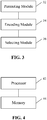
- Fig. 3 is a block diagram showing a structure of an apparatus for sequence determination according to an embodiment of the present disclosure. As shown in Fig. 3 , the apparatus includes:
- a first bit sequence having a length of K bits is mapped to a specified position based on M_index to obtain a second bit sequence.
- Polar encoding is applied to the second bit sequence to obtain a Polar encoded bit sequence.
- T bits are selected based on the Polar encoded bit sequence as a bit sequence to be transmitted. That is, the present disclosure provides a method for determining a bit sequence to be transmitted, capable of solving the problem in the related art associated with lack of a sequence determination scheme in the 5G New RAT.
- the above apparatus may further include: a first transform module coupled to the above permuting module 32 and configured to apply a first predetermined transform to a first index matrix to obtain a second index matrix and obtain M_index based on the second index matrix.
- the first predetermined transform includes row permutation or column permutation. That is, in the Polar encoding process, the same transform pattern is applied to one dimension of the first index matrix, such that only the other dimension of the first index matrix needs to be changed when a mother code length changes.
- the hardware can be reused in the implementation of Polar codes, thereby solving the problem in the related art associated with incapability of hardware reuse in the Polar encoding process.
- the apparatus may further include: a second transform module configured to form a first bit sequence matrix from the Polar encoded bit sequence, and apply a second predetermined transform to the first bit sequence matrix to obtain a second bit sequence matrix.
- the second predetermined transform includes row permutation or column permutation.
- the selecting module is further configured to select T bits based on the second bit sequence matrix as the bit sequence to be transmitted. That is, the same transform pattern is applied to one dimension of the first index matrix, such that only the other dimension of the first index matrix needs to be changed when a mother code length changes.
- the hardware can be further reused in the implementation of Polar codes, thereby further solving the problem in the related art associated with incapability of hardware reuse in the Polar encoding process.
- the above apparatus may further include a storage module coupled to the above first transform module and configured to store the second bit sequence matrix.
- the above storage module can be, but not limited to, a buffer or any other memory, such as an internal memory or any other logic entity.
- the above first index matrix can be, but not limited to, a two dimensional, three dimensional or multi-dimensional matrix.
- the above first predetermined transform can be embodied such that a row transform pattern or a column transform pattern for the first index matrix is the same.
- the second index matrix is M re , which is a matrix of R re rows and C re columns.
- the above first transform module is further configured to obtain the second index matrix according to at least one of: the i-th column of M re being obtained from the ⁇ 1 (i)-th column of M or by means of column permutation, where 0 ⁇ i ⁇ C re -1, 0 ⁇ 1 (i) ⁇ C re -1, R re ⁇ C re ⁇ N, and i and ⁇ 1 (i) are both non-negative integers; or the j-th row of M re being obtained from the ⁇ 2 (j)-th row of M or , where 0 ⁇ j ⁇ R re -1, 0 ⁇ 2 (j) ⁇ R re -1, R re ⁇ C re ⁇ N, and j and ⁇ 2 (j) are both non-negative integers.
- ⁇ 1 (i) can be obtained according to at least one of:
- ⁇ 2 (j) can be obtained according to at least one of:
- the above first bit sequence matrix can be, but not limited to, a two dimensional, three dimensional or multi-dimensional matrix.
- the above second predetermined transform can be embodied such that a row transform pattern or a column transform pattern for the first bit sequence matrix is the same.
- the first bit sequence matrix is M og .
- the second bit sequence matrix is M vb , which is a matrix of R vb rows and C vb columns.
- C vb is a minimum value satisfying R vb ⁇ C vb ⁇ N; or when C vb is constant, R vb is a minimum value satisfying R vb ⁇ C vb ⁇ N.
- the above second transform module can further be configured to obtain the second bit sequence matrix according to at least one of: the g-th column of M vb being obtained from the ⁇ 3 (g)-th column of M og by means of column permutation, where 0 ⁇ g ⁇ C vb -1, 0 ⁇ 3 (g) ⁇ C vb -1, R vb ⁇ C vb ⁇ N, and g and ⁇ 3 (g) are both non-negative integers; or the h-th row of M vb being obtained from the ⁇ 4 (h)-th row of M og by means of row permutation, where 0 ⁇ h ⁇ R vb -1, 0 ⁇ 4 (h) ⁇ R vb -1, R vb ⁇ C vb ⁇ N, and h and ⁇ 4 (h) are both non-negative integers.
- ⁇ 3 (g) can be obtained according to at least one of:
- ⁇ 4 (h) can be obtained according to at least one of:
- the above first transform module can further be configured to select a predetermined number of indices based on M re row by row, column by column or diagonal by diagonal, as M_index.
- each index corresponding to a non-transmitted bit sequence in a second bit sequence matrix is skipped.
- the second bit sequence matrix is obtained from a first bit sequence matrix by using a second predetermined transform.
- the first bit sequence matrix is formed from the Polar encoded bit sequence.
- the second predetermined transform includes row permutation or column permutation.
- the above selecting module 36 can further be configured to select T bits based on the second bit sequence matrix row by row, column by column or diagonal by diagonal, as the bit sequence to be transmitted.
- the above selecting module 36 can further be configured to select T bits from the second bit sequence matrix row by row, column by column or diagonal by diagonal, from a starting position t in the second bit sequence matrix. When the selection reaches the first or last bit in the second bit sequence matrix, it continues with the last or first bit in the second bit sequence matrix, where 1 ⁇ t ⁇ R vb ⁇ C vb .
- the above selecting module 36 can further be configured to select the 1 st to T-th bits or the (N-T+1)-th to N-th bits from the second bit sequence matrix column by column, when T is smaller than or equal to a length N of the Polar encoded bit sequence; select the 1 st to T-th bits or the (N-T+1)-th to N-th bits from the second bit sequence matrix row by row, when T is smaller than or equal to the length N of the Polar encoded bit sequence; select the 1 st to T-th bits or the (N-T+1)-th to N-th bits from the second bit sequence matrix diagonal by diagonal, when T is smaller than or equal to the length N of the Polar encoded bit sequence; select, when T is larger than the length N of the Polar encoded bit sequence, T bits row by row, column by column or diagonal by diagonal, from the t-th bit in the second bit sequence matrix.
- the above apparatus can be, but not limited to be, provided in a terminal or a network device such as a base station.
- each of the above-described modules can be implemented by means of software or hardware, and the latter can be implemented in, but not limited to, the following manner: the above-described modules can be located at the same processor, or can be distributed over a plurality of processors in any combination.
- Embodiment 3 of the present disclosure provides a device.
- Fig. 4 is a block diagram showing a structure of a device according to Embodiment 3 of the present disclosure. AS shown in Fig. 4 , the device includes:
- a first bit sequence having a length of K bits is mapped to a specified position based on M_index to obtain a second bit sequence.
- Polar encoding is applied to the second bit sequence to obtain a Polar encoded bit sequence.
- T bits are selected based on the Polar encoded bit sequence as a bit sequence to be transmitted. That is, the present disclosure provides a method for determining a bit sequence to be transmitted, capable of solving the problem in the related art associated with lack of a sequence determination scheme in the 5G New RAT.
- the above processor 42 can further be configured to: apply a first predetermined transform to a first index matrix to obtain a second index matrix; and obtain M_index based on the second index matrix.
- the first predetermined transform includes row permutation or column permutation. That is, in the Polar encoding process, the same transform pattern is applied to one dimension of the first index matrix, such that only the other dimension of the first index matrix needs to be changed when a mother code length changes.
- the hardware can be reused in the implementation of Polar codes, thereby solving the problem in the related art associated with incapability of hardware reuse in the Polar encoding process.
- the above processor 42 can further be configured to: write the Polar encoded bit sequence into a first bit sequence matrix; and apply a second predetermined transform to the first bit sequence matrix to obtain a second bit sequence matrix.
- the second predetermined transform includes row permutation or column permutation.
- a selecting module is configured to select T bits based on the second bit sequence matrix as the bit sequence to be transmitted. That is, the same transform pattern is applied to one dimension of the first index matrix, such that only the other dimension of the first index matrix needs to be changed when a mother code length changes.
- the hardware can be further reused in the implementation of Polar codes, thereby further solving the problem in the related art associated with incapability of hardware reuse in the Polar encoding process.
- the above storage module can be configured to store the above second bit sequence matrix.
- the above storage module can be, but not limited to, a buffer or any other memory, such as an internal memory or any other logic entity.
- the above first index matrix can be, but not limited to, a two dimensional, three dimensional or multi-dimensional matrix.
- the above first predetermined transform can be embodied such that a row transform pattern or a column transform pattern for the first index matrix is the same.
- the second index matrix is M re , which is a matrix of R re rows and C re columns.
- the above processor 42 can further be configured to obtain the second index matrix according to at least one of: the i-th column of M re being obtained from the ⁇ 1 (i)-th column of M or by means of column permutation, where 0 ⁇ i ⁇ C re -1, 0 ⁇ 1 (i) ⁇ C re -1, R re ⁇ C re ⁇ N, and i and ⁇ 1 (i) are both non-negative integers; or the j-th row of M re being obtained from the ⁇ 2 (j)-th row of M or , where 0 ⁇ j ⁇ R re -1, 0 ⁇ 2 (j) ⁇ R re -1, R re ⁇ C re ⁇ N, and j and ⁇ 2 (j) are both non-negative integers.
- ⁇ 1 (i) can be obtained according to at least one of:
- ⁇ 2 (j) can be obtained according to at least one of:
- the above first bit sequence matrix can be, but not limited to, a two dimensional, three dimensional or multi-dimensional matrix.
- the above second predetermined transform can be embodied such that a row transform pattern or a column transform pattern for the first bit sequence matrix is the same.
- the first bit sequence matrix is M og .
- the second bit sequence matrix is M vb , which is a matrix of R vb rows and C vb columns.
- C vb is a minimum value satisfying R vb ⁇ C vb ⁇ N; or when C vb is constant, R vb is a minimum value satisfying R vb ⁇ C vb ⁇ N.
- the above processor 42 can further be configured to obtain the second bit sequence matrix according to at least one of: the g-th column of M vb being obtained from the ⁇ 3 (g)-th column of M og by means of column permutation, where 0 ⁇ g ⁇ C vb -1, 0 ⁇ 3 (g) ⁇ C vb -1, R vb ⁇ C vb ⁇ N, and g and ⁇ 3 (g) are both non-negative integers; or the h-th row of M vb being obtained from the ⁇ 4 (h)-th row of M og by means of row permutation, where 0 ⁇ h ⁇ R vb -1, 0 ⁇ 4 (h) ⁇ R vb -1, R vb ⁇ C vb ⁇ N, and h and ⁇ 4 (h) are both non-negative integers.
- ⁇ 3 (g) can be obtained according to at least one of:
- ⁇ 4 (h) can be obtained according to at least one of:
- the above first transform module can further be configured to select a predetermined number of indices based on M re row by row, column by column or diagonal by diagonal, as M_index.
- each index corresponding to a non-transmitted bit sequence in a second bit sequence matrix is skipped.
- the second bit sequence matrix is obtained from a first bit sequence matrix by using a second predetermined transform.
- the first bit sequence matrix is formed from the Polar encoded bit sequence.
- the second predetermined transform includes row permutation or column permutation.
- processor 42 can further be configured to select T bits based on the second bit sequence matrix row by row, column by column or diagonal by diagonal, as the bit sequence to be transmitted.
- the above processor 42 can further be configured to select T bits based on the second bit sequence matrix row by row, column by column or diagonal by diagonal, from a starting position t in the second bit sequence matrix. When the selection reaches the first or last bit in the second bit sequence matrix, it continues with the last or first bit in the second bit sequence matrix, where 1 ⁇ t ⁇ R b ⁇ C vb .
- the above processor 42 can further be configured to select the 1 st to T-th bits or the (N-T+1)-th to N-th bits from the second bit sequence matrix column by column, when T is smaller than or equal to a length N of the Polar encoded bit sequence; select the 1 st to T-th bits or the (N-T+1)-th to N-th bits from the second bit sequence matrix row by row, when T is smaller than or equal to the length N of the Polar encoded bit sequence; select the 1 st to T-th bits or the (N-T+1)-th to N-th bits from the second bit sequence matrix diagonal by diagonal, when T is smaller than or equal to the length N of the Polar encoded bit sequence; select, when T is larger than the length N of the Polar encoded bit sequence, T bits row by row, column by column or diagonal by diagonal, from the t-th bit in the second bit sequence matrix.
- the selection reaches the first or last bit in the second bit sequence matrix, it continues with the last or first bit in the second bit sequence matrix,
- the above device can be, but not limited to a terminal or a network device such as a base station.
- a storage medium stores a program which, when executed, performs any of the above described methods.
- the above storage medium can be configured to store program codes for performing the steps of the method described above in connection with Embodiment 1.
- the above storage medium may include, but not limited to, a USB disk, a Read-Only Memory (ROM), a Random Access Memory (RAM), a mobile hard disk, a magnetic disk, an optical disc, or other mediums capable of storing program codes.
- a processor is provided.
- the processor is configured to execute a program for performing the steps of any of the above described methods.
- the above program is configured to perform the steps of the method described above in connection with Embodiment 1.
- the number of columns in each of the index matrix M or , the index matrix M re , the bit sequence matrix M vb and the bit sequence matrix M og is fixed to be 32.
- Polar encoding having a mother code length of 128 is applied.
- the encoding process is as follows.
- each of the index matrix M or , the index matrix M re , the bit sequence matrix M vb and the bit sequence matrix M og is fixed to be 32.
- Polar encoding having a mother code length of 128 is applied.
- the number of columns in each of the index matrix M or , the index matrix M re , the bit sequence matrix M vb and the bit sequence matrix M og is fixed to be 32.
- Polar encoding having a mother code length of 128 is applied.
- the selection When the selection reaches the last bit y 127 in the buffer or in the bit sequence matrix M vb , it continues with the first bit y 0 of the bit sequence matrix M vb .
- the resulting bit sequent to be transmitted is ⁇ y 0 ,y 1 ,y 2 ,...,y 127 ,y 0 ,y 1 ,y 2 ⁇ .
- the number of columns in each of the index matrix M or , the index matrix M re , the bit sequence matrix M vb and the bit sequence matrix M og is fixed to be 32.
- Polar encoding having a mother code length of 128 is applied.
- the selection When the selection reaches the first bit y 0 in the buffer or in the bit sequence matrix M vb , it continues with the last bit y 127 of the bit sequence matrix M vb .
- the resulting bit sequent to be transmitted is ⁇ y 0 ,y 1 ,y 2 ,...,y 127 ,y 127 ,y 126 ,y 125 ⁇ .
- the number of columns in each of the index matrix M or , the index matrix M re , the bit sequence matrix M vb and the bit sequence matrix M og is fixed to be 32.
- Polar encoding having a mother code length of 128 is applied.
- the number of columns in each of the index matrix M or , the index matrix M re , the bit sequence matrix M vb and the bit sequence matrix M og is fixed to be 32.
- Polar encoding having a mother code length of 128 is applied.
- the number of columns in each of the index matrix M or , the index matrix M re , the bit sequence matrix M vb and the bit sequence matrix M og is fixed to be 32.
- Polar encoding having a mother code length of 128 is applied.
- the number of columns in each of the index matrix M or , the index matrix M re , the bit sequence matrix M vb and the bit sequence matrix M og is fixed to be 32.
- Polar encoding having a mother code length of 128 is applied.
- each of the index matrix M or , the index matrix M re , the bit sequence matrix M vb and the bit sequence matrix M og is fixed to be 32.
- Polar encoding having a mother code length of 128 is applied.
- the encoding process is different from Example 1 in that a different rate matching scheme is used. Details of the operations will be omitted here.
- each of the index matrix M or , the index matrix M re , the bit sequence matrix M vb and the bit sequence matrix M og is fixed to be 32.
- Polar encoding having a mother code length of 128 is applied.
- the encoding process is different from Example 2 in that a different rate matching scheme is used. Details of the operations will be omitted here.
- each of the index matrix M or , the index matrix M re , the bit sequence matrix M vb and the bit sequence matrix M og is fixed to be 32.
- Polar encoding having a mother code length of 128 is applied.
- the encoding process is different from Example 3 in that a different rate matching scheme is used. Details of the operations will be omitted here.
- each of the index matrix M or , the index matrix M re , the bit sequence matrix M vb and the bit sequence matrix M og is fixed to be 32.
- Polar encoding having a mother code length of 128 is applied.
- the encoding process is different from Example 4 in that a different rate matching scheme is used. Details of the operations will be omitted here.
- modules or steps of the present disclosure can be implemented by a general purpose computing device, and can be centralized at one single computing device or distributed over a network of multiple computing devices.
- they can be implemented by means of computer executable program codes, which can be stored in a storage device and executed by one or more computing devices.
- the steps shown or described herein may be performed in an order different from the one described above.
- they can be implemented separately in individual integrated circuit modules, or one or more of the modules or steps can be implemented in one single integrated circuit module.
- the present disclosure is not limited to any particular hardware, software, and combination thereof.
- a first bit sequence having a length of K bits is mapped to a specified position based on M_index to obtain a second bit sequence.
- Polar encoding is applied to the second bit sequence to obtain a Polar encoded bit sequence.
- T bits are selected based on the Polar encoded bit sequence as a bit sequence to be transmitted. That is, the present disclosure provides a method for determining a bit sequence to be transmitted, capable of solving the problem in the related art associated with lack of a sequence determination scheme in the 5G New RAT.
Landscapes
- Engineering & Computer Science (AREA)
- Physics & Mathematics (AREA)
- Theoretical Computer Science (AREA)
- Probability & Statistics with Applications (AREA)
- Mathematical Physics (AREA)
- General Physics & Mathematics (AREA)
- Computational Mathematics (AREA)
- Mathematical Analysis (AREA)
- Mathematical Optimization (AREA)
- Pure & Applied Mathematics (AREA)
- Computer Networks & Wireless Communication (AREA)
- Signal Processing (AREA)
- Computing Systems (AREA)
- Algebra (AREA)
- Data Mining & Analysis (AREA)
- General Engineering & Computer Science (AREA)
- Quality & Reliability (AREA)
- Databases & Information Systems (AREA)
- Software Systems (AREA)
- Error Detection And Correction (AREA)
- Compression, Expansion, Code Conversion, And Decoders (AREA)
- Compression Or Coding Systems Of Tv Signals (AREA)
- Complex Calculations (AREA)
- Signal Processing For Digital Recording And Reproducing (AREA)
Abstract
Description
- The present disclosure claims priorities to Chinese Patent Application No.
201710314013.X, filed on May 5, 2017 201710737955.9, filed on August 24, 2017 - The present disclosure relates to communication technology, and more particularly, to a method and an apparatus for sequence determination, a device and a storage medium.
- Due to the presence of channel noise, a channel coding, as an independent part of a mobile communication system, guarantees the reliability, accuracy and effectiveness of information delivery.
- Polar coding is a constructive coding scheme that has been strictly proven to be capable of reaching a channel capacity. Polar code is capable of satisfying requirements of the 5th Generation (5G) New Radio Access Technology (RAT) with respect to communication throughput and latency. A codeword encoded by Polar code can be represented as x=u·G N , where u=(u1,...,uN) is composed of information bits, known bits and parity check bits,


- Due to the Polarization characteristics of the Polar codes, input bits have different reliabilities, i.e., input bits at different positions have different Bit Error Rates (BERs). In order to improve a decoding performance, the information bits and the parity check bits are placed at positions having high reliabilities (i.e., positions having low BERs) and the known bits are placed at positions having low reliabilities in an encoding process, such that the Block Error Rate (BLER) can be effectively reduced.
- Conventionally, for different mother code lengths of Polar codes, different hardware implementations would be required for permutation and rate matching of the information bits, parity check bits and known bits, which is highly complicated.
- Currently, there are no effective solutions to the above problem in the related art.
- The embodiments of the present disclosure provide a method and an apparatus for sequence determination, a device and a storage medium, capable of solving the problem in the related art associated with lack of a sequence determination scheme in the 5G New RAT.
- According to an embodiment of the present disclosure, a method for sequence determination is provided. The method includes: mapping a first bit sequence having a length of K bits to a position based on M_index to obtain a second bit sequence; applying Polar encoding to the second bit sequence to obtain a Polar encoded bit sequence; and selecting T bits based on the Polar encoded bit sequence as a bit sequence to be transmitted, where K and T are both non-negative integers and K≤T.
- In an embodiment of the present disclosure, the method further includes, prior to mapping the first bit sequence having the length of K bits to the specified position based on M_index to obtain the second bit sequence: applying a first predetermined transform to a first index matrix to obtain a second index matrix and obtaining M index based on the second index matrix. The first predetermined transform includes row permutation or column permutation.
- In an embodiment of the present disclosure, the method further includes, prior to selecting T bits from the Polar encoded bit sequence as the bit sequence to be transmitted: forming a first bit sequence matrix based on the Polar encoded bit sequence; and applying a second predetermined transform to the first bit sequence matrix to obtain a second bit sequence matrix. The second predetermined transform includes row permutation or column permutation. The operation of selecting T bits based on the Polar encoded bit sequence as the bit sequence to be transmitted includes: selecting T bits based on the second bit sequence matrix as the bit sequence to be transmitted.
- In an embodiment of the present disclosure, the second index matrix is Mre, which is a matrix of Rre rows and Cre columns. The first index matrix is Mor, which is:


- In an embodiment of the present disclosure, when Rre is constant, Cre is a minimum value satisfying Rre×Cre≥N; or when Cre is constant, Rre is a minimum value satisfying Rre×Cre≥N.
- In an embodiment of the present disclosure, the operation of applying the first predetermined transform to the first index matrix to obtain the second index matrix includes at least one of: the i-th column of Mre being obtained from the π1(i)-th column of Mor by means of column permutation, where 0≤i≤Cre-1, 0≤π1(i)≤Cre-1, Rre×Cre≥N, and i and π1(i) are both non-negative integers; or the j-th row of Mre being obtained from the π2(j)-th row of Mor, where 0≤j≤Rre-1, 0≤π2(j)≤Rre-1, Rre×Cre≥N, and j and π2(j) are both non-negative integers.
- In an embodiment of the present disclosure, π1(i) is obtained as at least one of: π1(i)=BRO(i), where BRO() denotes a bit reverse ordering operation which includes: converting a decimal number i into a first binary number (Bn1-1,Bn1-2,...,B0), reversing the first binary number to obtain a second binary number (B0,B1,...,Bn1-1) and converting the second binary number into a decimal number π1(i), where n1=log2(Cre) and 0≤i≤Cre-1; π1(i)={S1,S2,S3}, where S1={0,1,...,i1-1}, S2={i2,i3,i2+1,i3+1,...,i4,i5}, and S3 is a set of elements in {0,1,..., Cre-1} other than those included in S1 and S2, where Cre/8≤i1≤i2≤Cre/3, i2≤i4≤i3≤2Cre/3, i3≤i5≤Cre-1, i1, i2, i3, i4 and i5 are all non-negative integers, and an intersection of any two of S1, S2 and S3 is null; or π1(i)={I}, where {1} is a sequence obtained by organizing numerical results of applying a function f(r) to column indices r of Mor in ascending or descending order, where 0≤r≤Cre-1.
- In an embodiment of the present disclosure, f(r) includes at least one of:


- In an embodiment of the present disclosure, π2(j) is obtained as at least one of: π2(j)=BRO(j), where BRO() denotes a bit reverse ordering operation which includes: converting a decimal number j into a third binary number (Bn2-1,Bn2-2,... ,B0), reversing the third binary number to obtain a fourth binary number (B0,B1,...,Bn2-1) and converting the fourth binary number into a decimal number π2(j), where n2=log2(Rre) and 0≤j≤Rre-1; π2(j)={S4,S5,S6}, where S4=10,1,...,j1-1}, S5={j2,j3,j2+1,j3+1,...,j4,j5}, and S6 is a set of elements in {0,1,..., Rre-1} other than those included in S4 and S5, where Rre/8≤j1≤j2≤Rre/3,j2≤j4≤j3≤2Rre/3,j3≤j5≤Rre-1, j1, j2, j3, j4 and j5 are all non-negative integers, and an intersection of any two of S4, S5 and S6 is null; or π2(j)={J}, where {J} is a sequence obtained by organizing numerical results of applying a function f(s) to row indices s of Mor in ascending or descending order, where 0≤s≤Rre-1.
- In an embodiment of the present disclosure, f(s) includes at least one of:


- In an embodiment of the present disclosure, the first bit sequence matrix is Mog. The second bit sequence matrix is Mvb, which is a matrix of Rvb rows and Cvb columns. Mog is:


- In an embodiment of the present disclosure, when Rvb is constant, Cvb is a minimum value satisfying Rvb×Cvb≥N; or when Cvb is constant, Rvb is a minimum value satisfying Rvb×Cvb≥N.
- In an embodiment of the present disclosure, the operation of applying the second predetermined transform to the first bit sequence matrix to obtain the second bit sequence matrix includes at least one of: the g-th column of Mvb being obtained from the π3(g)-th column of Mog by means of column permutation, where 0≤g≤Cvb-1, 0≤π3(g)≤Cvb-1, Rvb×Cvb≥N, and g and π3(g) are both non-negative integers; or the h-th row of Mvb being obtained from the π4(h)-th row of Mog by means of row permutation, where 0≤h≤Rvb-1, 0≤π4(h)≤Rvb-1, Rvb×Cvb≥N, and h and π4(h) are both non-negative integers.
- In an embodiment of the present disclosure, π3(g) is obtained as at least one of: π3(g)=BRO(g), where BRO() denotes a bit reverse ordering operation which includes: converting a decimal number g into a fifth binary number (Bn3-1,Bn3-2,... ,B0), reversing the fifth binary number to obtain a sixth binary number (B0,B11,...,Bn3-1) and converting the sixth binary number into a decimal number π3(g), where n3=log2(Cvb) and 0≤g≤Cvb-1; π3(g)={S1,S2,S3}, where S1={0,1,...,g1-1}, S2={g2,g3,g2+1,g3+1,...,g4,g5}, and S3 is a set of elements in {0,1,..., Cvb-1} other than those included in S1 and S2, where Cvb/8≤g1≤g2≤Cvb/3, g2≤g4≤g3≤2Cvb/3, g3≤g5≤Cvb-1, g1, g2, g3, g4 and g5 are all non-negative integers, and an intersection of any two of S1, S2 and S3 is null; π3(g)={G}, where {G} is a sequence obtained by organizing numerical results of applying a function f(α) to column indices α of Mog in ascending or descending order, where 0≤α≤Cvb-1; π3(g)= {Q1,Q2,Q3}, where Q2={ q1,q2,q1+1,q2+1,...,q3,q4}, 0≤q1<q3≤(Cvb-1)/2, 0≤q2<q4≤(Cvb-1)/2, q1, q2, q3, q4 and q5 are all non-negative integers, Q1 and Q3 are other elements in a difference set between {0,1, ..., Cvb-1} and Q2, and an intersection of any two of Q1, Q2 and Q3 is null; π3(g) being different from a predefined sequence V1 in nV1 positions, where V1={0,1,2,3,4,5,6,7,8,9,10,11,12,16,13,17,14,18,15,19,20,24,21,22, 25,26,28,23,27,29,30,31}, 0≤nV1≤23; or π3(g) being different from a predefined sequence V2 in nV2 positions, where V2={0, 1, 2, 4, 3, 5, 6, 7, 8, 16, 9, 17, 10, 18, 11, 19, 12, 20, 13, 21, 14, 22, 15, 23, 24, 25, 26, 28, 27, 29, 30, 31}, 0≤nV2≤3.
- In an embodiment of the present disclosure, f(α) includes at least one of:


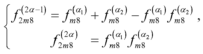

- In an embodiment of the present disclosure, π4(h) is obtained as at least one of: π4(h)=BPOP(h), where BRO() denotes a bit reverse ordering operation which includes: converting a decimal number h into a seventh binary number (Bn4-1,Bn4-2,...,B0), reversing the seventh binary number to obtain an eighth binary number (B0,B1,...,Bn4-1) and converting the eighth binary number into a decimal number π4(h), where n4=log2(Rvb) and 0≤h≤Rvb-1; π4(h)={S4,S5,S6}, where S4={0,1,... ,h1-1}, S5={h2,h3,h2+1,h3+1,...,h4,h5}, and S6 is a set of elements in {0,1,..., Rvb-1} other than those included in S4 and S5, where Rvb/8≤h1≤h2≤Rvb/3, h2≤h4≤h3≤2Rvb/3, h3≤h5≤Rvb-1, h1, h2, h3, h4 and h5 are all non-negative integers, and an intersection of any two of S4, S5 and S6 is null; π4(h)={H}, where {H} is a sequence obtained by organizing numerical results of applying a function f(β) to row indices β of Mog in ascending or descending order, where 0≤β≤Rvb-1; π4(h)= {O1,O2,O3}, where O2={o1,o2,o1+1,o2+1,...,o3,o4}, 0≤o1<o3≤(Rvb-1)/2, 0≤o2<o4≤(Rvb-1)/2, o1, o2, o3, o4 and o5 are all non-negative integers, O1 and 03 are other elements in a difference set between {0,1, ..., Rvb-1} and O2, and an intersection of any two of O1, O2 and O3 is null; π4(h) being different from a predefined sequence VV1 in n VV1 positions, where W1={0,1,2,3,4,5,6,7,8,9,10,11,12,16,13,17,14,18,15,19,20,24,21,22,25,26,28,23,27,29,30,31}, 0≤nVV1≤23; or π4(h) being different from a predefined sequence VV2 in nVV2 positions, where VV2={0, 1, 2, 4, 3, 5, 6, 7, 8, 16, 9, 17, 10, 18, 11, 19, 12, 20, 13, 21, 14, 22, 15, 23, 24, 25, 26, 28, 27, 29, 30, 31}, 0≤nVV2≤3.
- In an embodiment of the present disclosure, f(β) includes at least one of:


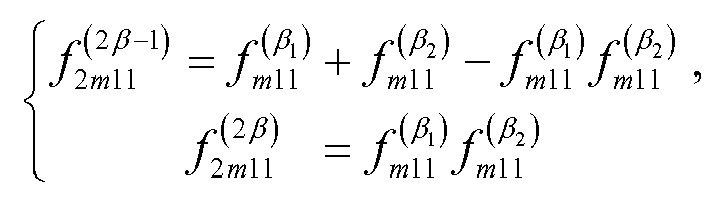

- In an embodiment of the present disclosure, the operation of obtaining M_index based on the second index matrix includes: selecting a predetermined number of indices from Mre row by row, column by column or diagonal by diagonal, as M_index.
- In an embodiment of the present disclosure, the operation of selecting the predetermined number of indices from Mre column by column includes: selecting Kp indices from the p-th column of Mre, where


- In an embodiment of the present disclosure, the operation of selecting the predetermined number of indices from Mre column by column includes at least one of: selecting Kic1 indices from the 1st, 2nd, ..., C1-th columns of Mre, where

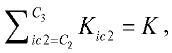

- In an embodiment of the present disclosure, the operation of selecting the predetermined number of indices from Mre row by row includes at least one of: selecting Kir1 indices from the 1st, 2nd, ..., R1-th rows of Mre, where


- In an embodiment of the present disclosure, the operation of selecting the predetermined number of indices from Mre diagonal by diagonal includes at least one of: selecting Kid1 indices from the (-min(Rre,Cre)+1)-th, (-min(Rre,Cre)+2)-th, ..., D1-th diagonals of Mre, where


- In an embodiment of the present disclosure, when the predetermined number of indices are selected from Mre row by row, column by column or diagonal by diagonal, each index corresponding to a non-transmitted bit sequence in a second bit sequence matrix is skipped. The second bit sequence matrix is obtained from a first bit sequence matrix by using a second predetermined transform. The first bit sequence matrix is formed from the Polar encoded bit sequence. The second predetermined transform includes row permutation or column permutation.
- In an embodiment of the present disclosure, the operation of selecting T bits based on the second bit sequence matrix as the bit sequence to be transmitted includes: selecting T bits based on the second bit sequence matrix row by row, column by column or diagonal by diagonal, as the bit sequence to be transmitted.
- In an embodiment of the present disclosure, the operation of selecting T bits based on the second bit sequence matrix row by row, column by column or diagonal by diagonal as the bit sequence to be transmitted includes: selecting T bits based on the second bit sequence matrix row by row, column by column or diagonal by diagonal, from a starting position t in the second bit sequence matrix. When the selection reaches the first or last bit in the second bit sequence matrix, it continues with the last or first bit in the second bit sequence matrix, where 1≤t≤Rvb×Cvb.
- In an embodiment of the present disclosure, the operation of selecting T bits based on the second bit sequence matrix row by row, column by column or diagonal by diagonal as the bit sequence to be transmitted includes: selecting the 1st to T-th bits or the (N-T+1)-th to N-th bits from the second bit sequence matrix column by column, when T is smaller than or equal to a length N of the Polar encoded bit sequence; selecting the 1st to T-th bits or the (N-T+1)-th to N-th bits from the second bit sequence matrix row by row, when T is smaller than or equal to the length N of the Polar encoded bit sequence; selecting the 1st to T-th bits or the (N-T+1)-th to N-th bits from the second bit sequence matrix diagonal by diagonal, when T is smaller than or equal to the length N of the Polar encoded bit sequence; selecting, when T is larger than the length N of the Polar encoded bit sequence, T bits row by row, column by column or diagonal by diagonal, from the t-th bit in the second bit sequence matrix. When the selection reaches the first or last bit in the second bit sequence matrix, it continues with the last or first bit in the second bit sequence matrix, where 1≤t≤Rvb×Cvb and N is a non-negative integer.
- In an embodiment of the present disclosure, the operation of selecting T bits from the second bit sequence matrix column by column includes at least one of: selecting Tie1 bits from the 1st, 2nd, ..., E1-th columns , where


- In an embodiment of the present disclosure, the operation of selecting T bits from the second bit sequence matrix row by row includes at least one of: selecting Tif1 bits from the 1st, 2nd, ..., F1-th rows, where


- In an embodiment of the present disclosure, the operation of selecting T bits from the second bit sequence matrix diagonal by diagonal includes at least one of: selecting Tig1 bits from the (-min(Rvb,Cvb)+1)-th, (-min(Rvb,Cvb)+2)-th, ..., Gi-th diagonals , where


- In an embodiment of the present disclosure, Mog has 32 columns.
- According to an embodiment of the present disclosure, an apparatus for sequence determination is provided. The apparatus includes: a permuting module configured to map a first bit sequence having a length of K bits to a specified position based on M_index to obtain a second bit sequence; an encoding module configured to apply Polar encoding to the second bit sequence to obtain a Polar encoded bit sequence; and a selecting module configured to select T bits based on the Polar encoded bit sequence as a bit sequence to be transmitted, where K and T are both non-negative integers and K≤T.
- In an embodiment of the present disclosure, the apparatus further includes: a first transform module configured to apply a first predetermined transform to a first index matrix to obtain a second index matrix and obtain M_index based on the second index matrix. The first predetermined transform includes row permutation or column permutation.
- In an embodiment of the present disclosure, the apparatus further includes: a second transform module configured to form a first bit sequence matrix from the Polar encoded bit sequence, and apply a second predetermined transform to the first bit sequence matrix to obtain a second bit sequence matrix. The second predetermined transform includes row permutation or column permutation. The selecting module is further configured to select T bits based on the second bit sequence matrix as the bit sequence to be transmitted.
- In an embodiment of the present disclosure, the second index matrix is Mre, which is a matrix of Rre rows and Cre columns. The first index matrix is Mor, which is:


- In an embodiment of the present disclosure, when Rre is constant, Cre is a minimum value satisfying Rre×Cre≥N; or when Cre is constant, Rre is a minimum value satisfying Rre×Cre≥N. In an embodiment of the present disclosure, the first index matrix is configured such that the second index matrix is obtained according to at least one of: the i-th column of Mre being obtained from the π1(i)-th column of Mor by means of column permutation, where 0≤i≤Cre-1, 0≤π1(i)≤Cre-1, Rre×Cre≥N, and i and π1(i) are both non-negative integers; or the j-th row of Mre being obtained from the π2(j)-th row of Mor, where 0≤j≤Rre-1, 0≤π2(j)≤Rre-1, Rre×Cre≥N, and j and π2(j) are both non-negative integers.
- In an embodiment of the present disclosure, the first bit sequence matrix is Mog. The second bit sequence matrix is Mvb, which is a matrix of Rvb rows and Cvb columns. Mog is:


- In an embodiment of the present disclosure, when Rvb is constant, Cvb is a minimum value satisfying Rvb×Cvb≥N; or when Cvb is constant, Rvb is a minimum value satisfying Rvb×Cvb≥N. In an embodiment of the present disclosure, the first bit sequence matrix is configured such that the second bit sequence matrix is obtained according to at least one of: the g-th column of Mvb being obtained from the π3(g)-th column of Mog by means of column permutation, where 0≤g≤Cvb-1, 0≤π3(g)≤Cvb-1, Rvb×Cvb≥N, and g and π3(g) are both non-negative integers; or the h-th row of Mvb being obtained from the π4(h)-th row of Mog by means of row permutation, where 0≤h≤Rvb-1, 0≤π4(h)≤Rvb-1, Rvb×Cvb≥N, and h and π4(h) are both non-negative integers.
- In an embodiment of the present disclosure, Mog has 32 columns.
- According to an embodiment of the present disclosure, a device is provided. The device includes: a processor configured to: map a first bit sequence having a length of K bits to a specified position based on M_index to obtain a second bit sequence; apply Polar encoding to the second bit sequence to obtain a Polar encoded bit sequence; and select T bits based on the Polar encoded bit sequence as a bit sequence to be transmitted, where K and T are both non-negative integers and K≤T, and a memory coupled to the processor.
- In an embodiment of the present disclosure, the processor is further configured to: apply a first predetermined transform to a first index matrix to obtain a second index matrix; and obtain M_index based on the second index matrix. The first predetermined transform includes row permutation or column permutation.
- In an embodiment of the present disclosure, the processor is further configured to: form a first bit sequence matrix from the Polar encoded bit sequence; apply a second predetermined transform to the first bit sequence matrix to obtain a second bit sequence matrix; and select T bits based on the second bit sequence matrix as the bit sequence to be transmitted. The second predetermined transform includes row permutation or column permutation.
- In an embodiment of the present disclosure, the second index matrix is Mre, which is a matrix of Rre rows and Cre columns. The first index matrix is Mor, which is:


- In an embodiment of the present disclosure, when Rre is constant, Cre is a minimum value satisfying Rre×Cre≥N; or when Cre is constant, Rre is a minimum value satisfying Rre×Cre≥N.
- In an embodiment of the present disclosure, the processor is further configured to obtain the second index matrix according to at least one of: the i-th column of Mre being obtained from the π1(i)-th column of Mor by means of column permutation, where 0≤i≤Cre-1, 0≤π1(i)≤Cre-1, Rre×Cre≥N, and i and π1(i) are both non-negative integers; or the j-th row of Mre being obtained from the π2(j)-th row of Mor, where 0≤j≤Rre-1, 0≤π2(j)≤Rre-1, Rre×Cre≥N, and j and π2(j) are both non-negative integers.
- In an embodiment of the present disclosure, the first bit sequence matrix is Mog. The second bit sequence matrix is Mvb, which is a matrix of Rvb rows and Cvb columns. Mog is:


- In an embodiment of the present disclosure, when Rvb is constant, Cvb is a minimum value satisfying Rvb×Cvb≥N; or when Cvb is constant, Rvb is a minimum value satisfying Rvb×Cvb≥N. In an embodiment of the present disclosure, the processor is configured to obtain the second bit sequence matrix according to at least one of: the g-th column of Mvb being obtained from the π3(g)-th column of Mog by means of column permutation, where 0≤g≤Cvb-1, 0≤π3(g)≤Cvb-1, Rvb×Cvb≥N, and g and π3(g) are both non-negative integers; or the h-th row of Mvb being obtained from the π4(h)-th row of Mog by means of row permutation, where 0≤h≤Rb-1, 0≤π4(h)≤Rvb-1, Rvb×Cvb≥N, and h and π4(h) are both non-negative integers.
- In an embodiment of the present disclosure, Mog has 32 columns.
- According to another embodiment of the present disclosure, a storage medium is provided. The storage medium stores a program which, when executed, performs the method according to any of the above embodiments.
- According to yet another embodiment of the present disclosure, a processor is provided. The processor is configured to execute a program for performing the method according to any of the above embodiments.
- With the present disclosure, a first bit sequence having a length of K bits is mapped to a specified position based on M_index to obtain a second bit sequence. Polar encoding is applied to the second bit sequence to obtain a Polar encoded bit sequence. T bits are selected based on the Polar encoded bit sequence as a bit sequence to be transmitted. That is, the present disclosure provides a method for determining a bit sequence to be transmitted, capable of solving the problem in the related art associated with lack of a sequence determination scheme in the 5G New RAT.
- The present disclosure can be further understood with reference to the figures described below, which constitute a part of the present disclosure. The illustrative embodiments of the present disclosure and descriptions thereof are provided for explaining, rather than limiting, the present disclosure. In the figures:
-
Fig. 1 is a block diagram showing a hardware structure of a mobile terminal in which a method for sequence determination can be applied according to an embodiment of the present disclosure; -
Fig. 2 is a flowchart illustrating a method for sequence determination according to an embodiment of the present disclosure; -
Fig. 3 is a block diagram showing a structure of an apparatus for sequence determination according to an embodiment of the present disclosure; and -
Fig. 4 is a block diagram showing a structure of a device according to Embodiment 3 of the present disclosure. - In the following, the present disclosure will be described in detail with reference to the figures, taken in conjunction with the embodiments. The embodiments, and the features thereof, can be combined with each other, provided that they do not conflict.
- It is to be noted that, the terms such as "first", "second" and so on in the description, claims and figures are used for distinguishing among similar objects and do not necessarily imply any particularly order or sequence.
- The method according to Embodiment 1 of the present disclosure can be performed in a mobile terminal, a computer terminal or a similar computing device. When the method is performed in a mobile terminal for example,
Fig. 1 is a block diagram showing a hardware structure of a mobile terminal in which a method for sequence determination can be applied according to an embodiment of the present disclosure. As shown inFig. 1 , themobile terminal 10 can include: one or more processors 102 (only one is shown, including, but not limited to, a processing device such as a microprocessor or a Micro Control Unit (MCU) or a programmable logic device such as Field Programmable Gate Array (FPGA)), amemory 104 for storing data, and atransmission device 106 for providing communication functions. It can be appreciated by those skilled in the art that the structure shown inFig. 1 is illustrative only, and the structure of the above electronic device is not limited thereto. For example, themobile terminal 10 may include more or less components than those shown inFig. 1 , or have a different configuration from the one shown inFig. 1 . - The
memory 104 can store software programs and modules of software applications, e.g., program instructions/modules associated with the method for sequence determination according to an embodiment of the present disclosure. Theprocessor 102 performs various functional applications and data processing operations, i.e., performing the above method, by executing the software programs and modules stored in thememory 104. Thememory 104 may include a random cache or a non-volatile memory such as one or more magnetic storage devices, flash memories or other non-volatile solid-state memories. In some examples, thememory 104 may further include one or more memories provided remotely from theprocessor 102, which can be connected to themobile terminal 10 via a network. Examples of such network include, but not limited to, Internet, an intranet of an enterprise, a Local Area Network (LAN), a mobile communication network, or any combination thereof. - The
transmission device 106 can transmit or receive data via a network. The network can be e.g., a wireless network provided by a communication provider of themobile terminal 10. In an example, thetransmission device 106 includes a Network Interface Controller (NIC), which can be connected to other network devices via a base station for communication with Internet. In an example, thetransmission device 106 can be a Radio Frequency (RF) module for communicating with Internet wirelessly. - Alternatively, the method according to Embodiment 1 of the present disclosure can be, but not limited to be, performed in network device, e.g., a base station.
- In this embodiment, a method performed in the above mobile terminal or network device for sequence determination is provided.
Fig. 2 is a flowchart illustrating a method for sequence determination according to this embodiment. As shown inFig. 2 , the process includes the following steps. - At step S202, a first bit sequence having a length of K bits is mapped to a specified position based on M_index to obtain a second bit sequence.
- At step S204, Polar encoding is applied to the second bit sequence to obtain a Polar encoded bit sequence.
- At step S206, T bits are selected based on the Polar encoded bit sequence as a bit sequence to be transmitted, where K and T are both non-negative integers and K≤T.
- With the above steps, a first bit sequence having a length of K bits is mapped to a specified position based on M_index to obtain a second bit sequence. Polar encoding is applied to the second bit sequence to obtain a Polar encoded bit sequence. T bits are selected based on the Polar encoded bit sequence as a bit sequence to be transmitted. That is, the present disclosure provides a method for determining a bit sequence to be transmitted, capable of solving the problem in the related art associated with lack of a sequence determination scheme in the 5G New RAT.
- It is to be noted that the above method may further include, prior to the step S202: applying a first predetermined transform to a first index matrix to obtain a second index matrix and obtaining M_index based on the second index matrix. The first predetermined transform includes row permutation or column permutation. That is, in the Polar encoding process, the same transform pattern is applied to one dimension of the first index matrix, such that only the other dimension of the first index matrix needs to be changed when a mother code length changes.
- Thus, the hardware can be reused in the implementation of Polar codes, thereby solving the problem in the related art associated with incapability of hardware reuse in the Polar encoding process.
- It is to be noted that the method can further include, prior to selecting T bits based on the Polar encoded bit sequence as the bit sequence to be transmitted: forming a first bit sequence matrix from the Polar encoded bit sequence; and applying a second predetermined transform to the first bit sequence matrix to obtain a second bit sequence matrix. The second predetermined transform includes row permutation or column permutation. The operation of selecting T bits based on the Polar encoded bit sequence as the bit sequence to be transmitted includes: selecting T bits based on the second bit sequence matrix as the bit sequence to be transmitted. That is, the same transform pattern is applied to one dimension of the first index matrix, such that only the other dimension of the first index matrix needs to be changed when a mother code length changes.
- Thus, the hardware can be further reused in the implementation of Polar codes, thereby further solving the problem in the related art associated with incapability of hardware reuse in the Polar encoding process.
- It is to be noted that the above method can further include, subsequent to applying the second predetermined transform to the first bit sequence matrix to obtain the second bit sequence matrix: storing bit sequences in the second bit sequence matrix in a buffer and selecting T bits from the buffer as the bit sequence to be transmitted.
- It is to be noted that the above buffer can be, but not limited to be, embodied as another physical or logic entity.
- It is to be noted that the above first index matrix can be, but not limited to, a two dimensional, three dimensional or multi-dimensional matrix. In an example where the above first index matrix is a two dimensional matrix, the above first predetermined transform can be embodied such that a row transform pattern or a column transform pattern for the first index matrix is the same.
- In an example where the above first index matrix is a two dimensional matrix, in an embodiment of the present disclosure, the second index matrix is Mre, which is a matrix of Rre rows and Cre columns. The first index matrix is Mor, which is:


- It is to be noted that the above Rre and Cre have one of the following characteristics: when Rre is constant, Cre is a minimum value satisfying Rre×Cre≥N; or when Cre is constant, Rre is a minimum value satisfying Rre×Cre≥N.
- It is to be noted that the operation of applying the first predetermined transform to the first index matrix to obtain the second index matrix includes at least one of: the i-th column of Mre being obtained from the π1(i)-th column of Mor by means of column permutation, where 0≤i≤Cre-1, 0≤π1(i)≤Cre-1, Rre×Cre≥N, and i and π1(i) are both non-negative integers; or the j-th row of Mre being obtained from the π2(j)-th row of Mor, where 0≤j≤Rre-1, 0≤π2(j)≤Rre-1, Rre×Cre≥N, and j and π2(j) are both non-negative integers.
- In the Polar encoding process, as the permutation pattern from Mor to Mre is the same for each row, if the number of columns of each of Mor and Mre is fixed, when the mother code length of the Polar codes changes, only the number of rows of each of Mor and Mre needs to be changed.
- Alternatively, the permutation pattern from Mor to Mre can be the same for each column and, if the number of rows of each of Mor and Mre is fixed, when the mother code length of the Polar codes changes, only the number of columns of each of Mor and Mre needs to be changed. In this way, in the implementation of the Polar codes, if the hardware for mapping input bit sequences to input positions in the encoder is designed for the maximum mother code length Nmax, it also applies to situations where the mother code length is smaller than Nmax, which allows reuse of the hardware.
- It is to be noted that the number of columns of the above Mog is 32.
- It is to be noted that the above π1(i) can be obtained according to at least one of:
- Scheme 1: π1(i)=BKOP(i) where BRO() denotes a bit reverse ordering operation which includes: converting a decimal number i into a first binary number (Bn1-1,Bn1-2,...,B0), reversing the first binary number to obtain a second binary number (B0,B1,... ,Bn1-1) and converting the second binary number into a decimal number π1(i), where n1=log2(Cre) and 0≤i≤Cre-1;
- Scheme 2: π1(i)={S1,S2,S3}, where S1={0,1,...,i1-1}, S2={i2,i3,i2+1,i3+1,...,i4,i5}, and S3 is a set of elements in {0,1,..., Cre-1} other than those included in S1 and S2, where Cre/8≤i1≤i2≤Cre/3, i2≤i4≤i3≤2Cre/3, i3≤i5≤Cre-1, i1, i2, i3, i4 and i5 are all non-negative integers, and an intersection of any two of S1, S2 and S3 is null; or
- Scheme 3: π1(i)={I}, where {I} is a sequence obtained by organizing numerical results of applying a function f(r) to column indices r of Mor in ascending or descending order, where 0≤r≤Cre-1.
- The above three schemes will be explained with reference to the following examples.
- For Scheme 1, if Cre =8, i=6, then n1=log2(8)=3. i=6 is converted into a binary number (B2,B1,B0)=(1,1,0). The binary number (B2,B1,B0)=(1,1,0) is reversed to obtain (B0,B1,B2)=(0,1,1). (B0,B1,B2)=(0,1,1) is then converted into a decimal number π1(i)=3.
- For Scheme 2, if Cre=8, i1=2, i2=2, i3=4, i4=3 and i5=5, then S1={0,1}, S2={2,4,3,5}, S3={6,7}, and π1(i)={0,1, 2,4,3,5, 6,7}.
- For Scheme 3, Cre=8, {f(0),...,f(7)}={0,1,1.18,2.18,1.41,2.41,2.60,3.60}. f(0),..., f(7) is organized in ascending order to obtain π1(i)={1,2,3,5,4,6,7,8}.
- It is to be noted that f(r) includes at least one of:


initializing a function value corresponding to r as


(Let the initial value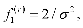


initializing a function value corresponding to r as


(Let


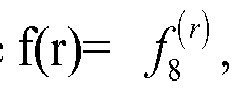
- It is to be noted that the above π2(j) can be obtained according to at least one of:
- π2(j)=BRO(j), where BRO() denotes a bit reverse ordering operation which includes: converting a decimal number j into a third binary number (Bn2-1,Bn2-2,...,B0), reversing the third binary number to obtain a fourth binary number (B0,B1,...,Bn2-1) and converting the fourth binary number into a decimal number π2(j), where n2=log2(Rre) and 0≤j≤Rre-1;
- π2(j)={S4,S5,S6}, where S4={0,1,...,j1-1}, SS={j2,j3,j2+1,j3+1,...,j4,j5}, and S6 is a set of elements in {0,1,..., Rre-1} other than those included in S4 and S5, where Rre/8≤j1≤j2≤Rre/3, j2≤j4≤j3≤2 Rre/3, j3≤j5≤Rre-1, j1, j2, j3, j4 and j5 are all non-negative integers, and an intersection of any two of S4, S5 and S6 is null; or
- π2(j)={J}, where {J} is a sequence obtained by organizing numerical results of applying a function f(s) to row indices s of Mor in ascending or descending order, where 0≤s≤Rre.
- It is to be noted that f(s) includes at least one of:
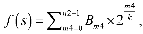
initializing a function value corresponding to s as f 1 (s), and obtaining a function value for each element

initializing a function value corresponding to s as f 1 (s), and obtaining a function value for each element

- It is to be noted that, for explanations for the above π2(j), reference can be made to π1(i).
- It is to be noted that the above first bit sequence matrix can be, but not limited to, a two dimensional, three dimensional or multi-dimensional matrix. In an example where the above first bit sequence matrix is a two dimensional matrix, the above second predetermined transform can be embodied such that a row transform pattern or a column transform pattern for the first bit sequence matrix is the same.
- It is to be noted that the first bit sequence matrix is Mog. The second bit sequence matrix is Mvb, which is a matrix of Rvb rows and Cvb columns. Mog is:


- It is to be noted that when Rvb is constant, Cvb is a minimum value satisfying Rvb×Cvb≥N; or when Cvb is constant, Rvb is a minimum value satisfying Rvb×Cvb≥N.
- It is to be noted that the operation of applying the second predetermined transform to the first bit sequence matrix to obtain the second bit sequence matrix can include at least one of: the g-th column of Mvb being obtained from the π3(g)-th column of Mog by means of column permutation, where 0≤g≤Cvb-1, 0≤π3(g)≤Cvb-1, Rvb×Cvb≥N, and g and π3(g) are both non-negative integers; or the h-th row of Mvb being obtained from the π4(h)-th row of Mog by means of row permutation, where 0≤h≤Rvb-1, 0≤π4(h)≤Rvb-1, Rvb×Cvb≥N, and h and π4(h) are both non-negative integers.
- In the encoding process, the process of selecting appropriate bits from the encoded bit sequence to form a bit sequence to be transmitted is a rate matching process. In the Polar encoding process, as the permutation pattern from Mog to Mvb is the same for each row, if the number of columns of each of Mog and Mvb is fixed, when the mother code length of the Polar codes changes, only the number of rows of each of Mog and Mvb needs to be changed. Alternatively, the permutation pattern from Mog to Mvb can be the same for each column and, if the number of rows of each of Mog and Mvb is fixed, when the mother code length of the Polar codes changes, only the number of columns of each of Mog and Mvb needs to be changed.
- In this way, in the implementation of the Polar codes, if the hardware for mapping input bit sequences to input positions in the encoder is designed for the maximum mother code length Nmax, it also applies to situations where the mother code length is smaller than Nmax, which allows reuse of the hardware.
- It is to be noted that π3(g) can be obtained according to at least one of:
- π3(g)=BRO(g), where BRO() denotes a bit reverse ordering operation which includes: converting a decimal number g into a fifth binary number (Bn3-1,Bn3-2,...,B0), reversing the fifth binary number to obtain a sixth binary number (B0,B11,...,Bn3-1) and converting the sixth binary number into a decimal number π3(g), where n3=log2(Cvb) and 0≤g≤Cvb-1;
- π3(g)={S1,S2,S3}, where S1={0,1,...,g1-1}, S2={g2,g3,g2+1,g3+1,...,g4,g5}, and S3 is a set of elements in {0,1,..., Cvb-1} other than those included in S1 and S2, where Cvb/8≤g1≤g2≤Cvb/3, g2≤g4≤g3≤2Cvb/3, g3≤g5≤Cvb-1, g1, g2, g3, g4 and g5 are all non-negative integers, and an intersection of any two of S1, S2 and S3 is null;
- π3(g)={G}, where {G} is a sequence obtained by organizing numerical results of applying a function f(α) to column indices α of Mog in ascending or descending order, where 0<α<Cvb-1; π3(g)= {Q1,Q2,Q3}, where Q2={ q1,q2,q1+1,q2+1,...,q3,q4}, 0≤q1≤q3≤(Cvb-1)/2, 0≤q2<q4≤(Cvb-1)/2, q1, q2, q3, q4 and q5 are all non-negative integers, Q1 and Q3 are other elements in a difference set between {0,1, ..., Cvb-1} and Q2, and an intersection of any two of Q1, Q2 and Q3 is null;
- π3(g) being different from a predefined sequence V1 in nV1 positions, where V1={0,1,2,3,4,5,6,7,8,9,10,11,12,16,13,17,14,18,15,19,20,24,21,22,25,26,28,23, 27,29,30,31}, 0≤nV1≤23; or
- π3(g) being different from a predefined sequence V2 in nV2 positions, where V2={0, 1, 2, 4, 3, 5, 6, 7, 8, 16, 9, 17, 10, 18, 11, 19, 12, 20, 13, 21, 14, 22, 15, 23, 24, 25, 26, 28, 27, 29, 30, 31}, 0≤nV2≤3.
- It is to be noted that f(α) includes at least one of:

initializing a function value corresponding to α as f 1 (α), and obtaining a function value for each element

initializing a function value corresponding to s as f 1 (α), and obtaining a function value for each element

- It is to be noted that π4(h) can be obtained according to at least one of:
- π4(h)=BRO(h) where BRO() denotes a bit reverse ordering operation which includes: converting a decimal number h into a seventh binary number (Bn4-1,Bn4-2,...,B0), reversing the seventh binary number to obtain an eighth binary number (B0,B1,...,Bn4-1) and converting the eighth binary number into a decimal number π4(h), where n4=log2(Rvb) and 0≤h≤Rvb-1;
- π4(h)={S4,S5,S6}, where S4={0,1,...,h1-1}, S5={h2,h3,h2+1,h3+1,...,h4,h5}, and S6 is a set of elements in {0,1,..., Rvb-1} other than those included in S4 and S5, where Rvb/8≤h1≤h2≤Rvb/3, h2≤h4≤h3≤2Rvb/3, h3≤h5≤Rvb-1, h1, h2, h3, h4 and h5 are all non-negative integers, and an intersection of any two of S4, S5 and S6 is null;
- π4(h)={H}, where {H} is a sequence obtained by organizing numerical results of applying a function f(β) to row indices β of Mog in ascending or descending order, where 0≤β≤Rvb-1;
- π4(h)= {O1,O2,O3}, where O2={o1,o2,o1+1,o2+1,...,o3,o4}, 0≤o1<o3≤(Rvb-1)/2, 0≤o2≤o4<(Rvb-1)/2, o1,o2,o3,o4 and o5 are all non-negative integers, O1 and 03 are other elements in a difference set between {0,1, ..., Rvb-1} and O2, and an intersection of any two of O1, O2 and 03 is null;
- π4(h) being different from a predefined sequence VV1 in nVV1 positions, where VV1={0,1,2,3,4,5,6,7,8,9,10,11,12,16,13,17,14,18,15,19,20,24,21,22,25,26,28,23,27,29,30,31}, 0≤nVV1≤23; or
- π4(h) being different from a predefined sequence VV2 in nVV2 positions, where VV2={0, 1, 2, 4, 3, 5, 6, 7, 8, 16, 9, 17, 10, 18, 11, 19, 12, 20, 13, 21, 14, 22, 15, 23, 24, 25, 26, 28, 27, 29, 30, 31}, 0≤nVV2≤3.
- It is to be noted that f(β) includes at least one of:

initializing a function value corresponding to β as f 1 (β), and obtaining a function value for each element

initializing a function value corresponding to β as f 1 (β), and obtaining a function value for each element

1≤m11≤n4, and β1, β2, 2β and 2β-1 are all integers larger than or equal to 0 and smaller than or equal to Rvb-1. - It is to be noted that, for explanations for π3(g) and π4(h), reference can be made to π1(i) and descriptions thereof will be omitted here.
- In an embodiment of the present disclosure, the operation of obtaining M_index based on the second index matrix includes: selecting a predetermined number of indices from Mre row by row, column by column or diagonal by diagonal, as M_index.
- In an embodiment of the present disclosure, the operation of selecting the predetermined number of indices from Mre column by column includes: selecting Kp indices from the p-th column of Mre, where

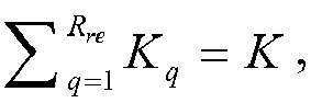

- In an embodiment of the present disclosure, the operation of selecting the predetermined number of indices from Mre column by column includes at least one of: selecting Kic1 indices from the 1st, 2nd, ..., C1-th columns of Mre, where


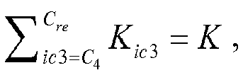
- In an embodiment of the present disclosure, the operation of selecting the predetermined number of indices from Mre row by row includes at least one of: selecting Kir1 indices from the 1st, 2nd, ..., R1-th rows of Mre, where


- In an embodiment of the present disclosure, the operation of selecting the predetermined number of indices from Mre diagonal by diagonal includes at least one of: selecting Kid1 indices from the (-min(Rre,Cre)+1)-th, (-min(Rre,Cre)+2)-th, ..., D1-th diagonals of Mre, where


- It is to be noted that, for a matrix M as an example, if M is a square matrix, the number, cc, of its columns is equal to the number, rr, of its rows. If the 0-th diagonal is the primary diagonal, the diagonals parallel with the primary diagonal are the 1st, 2nd, ..., (rr-1)-th diagonals from the bottom up, and the diagonals parallel with the primary diagonal are the -1st , -2nd, ..., (-rr+1)-th diagonals from the top down. If the 0-th diagonal is the secondary diagonal, the diagonals parallel with the secondary diagonal are the 1st, 2nd, ..., (rr-1)-th diagonals from the bottom up, and the diagonals parallel with the secondary diagonal are the -1st, -2nd, ..., (-rr+1)-th diagonals from the top down.
- It is to be noted that, for a matrix M as an example, if M is not a square matrix, the number, cc, of its columns can be larger than the number, rr, of its rows. For the matrix
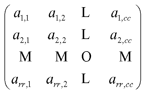
- It is to be noted that, for a matrix M as an example, if M is not a square matrix, the number, rr, of its rows can be larger than the number, cc, of its columns. For the matrix

- It is to be noted that, when the predetermined number of indices are selected from Mre row by row, column by column or diagonal by diagonal, each index corresponding to a non-transmitted bit sequence in a second bit sequence matrix is skipped. The second bit sequence matrix is obtained from a first bit sequence matrix by using a second predetermined transform. The first bit sequence matrix is formed from the Polar encoded bit sequence. The second predetermined transform includes row permutation or column permutation.
- It is to be noted that, if the encoded bit sequence is {x0,x1,x2,...,x15} and the bit sequence to be transmitted is {x6,x7,...,x15}, then the indices corresponding to the non-transmitted bit sequence are {0,1,2,..,5}. In this case, when the indices in M_index are selected based on Mre, the indices {0,1,2,..,5} are to be skipped.
- It is to be noted that the operation of selecting T bits based on the second bit sequence matrix as the bit sequence to be transmitted includes: selecting T bits based on the second bit sequence matrix row by row, column by column or diagonal by diagonal, as the bit sequence to be transmitted.
- It is to be noted that the operation of selecting T bits based on the second bit sequence matrix row by row, column by column or diagonal by diagonal as the bit sequence to be transmitted includes: selecting T bits based on the second bit sequence matrix row by row, column by column or diagonal by diagonal, from a starting position t in the second bit sequence matrix. When the selection reaches the first or last bit in the second bit sequence matrix, it continues with the last or first bit in the second bit sequence matrix, where 1≤t≤Rvb×Cvb.
- It is to be noted that the operation of selecting T bits based on the second bit sequence matrix row by row, column by column or diagonal by diagonal as the bit sequence to be transmitted includes: selecting the 1st to T-th bits or the (N-T+1)-th to N-th bits from the second bit sequence matrix column by column, when T is smaller than or equal to a length N of the Polar encoded bit sequence; selecting the 1st to T-th bits or the (N-T+1)-th to N-th bits from the second bit sequence matrix row by row, when T is smaller than or equal to the length N of the Polar encoded bit sequence; selecting the 1st to T-th bits or the (N-T+1)-th to N-th bits from the second bit sequence matrix diagonal by diagonal, when T is smaller than or equal to the length N of the Polar encoded bit sequence; selecting, when T is larger than the length N of the Polar encoded bit sequence, T bits row by row, column by column or diagonal by diagonal, from the t-th bit in the second bit sequence matrix. When the selection reaches the first or last bit in the second bit sequence matrix, it continues with the last or first bit in the second bit sequence matrix, where 1≤t≤Rvb×Cvb and N is a non-negative integer.
- It is to be noted that the operation of selecting T bits from the second bit sequence matrix column by column includes at least one of: selecting Tie1 bits from the 1st, 2nd, ..., E1-th columns , where


- It is to be noted that the operation of selecting T bits from the second bit sequence matrix row by row includes at least one of: selecting Tif1 bits from the 1st, 2nd, ..., F1-th rows , where
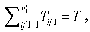


- It is to be noted that the operation of selecting T bits from the second bit sequence matrix diagonal by diagonal includes at least one of: selecting Tig1 bits from the (-min(Rvb,Cvb)+1)-th, (-min(Rvb,Cvb)+2)-th, ..., G1-th diagonals , where
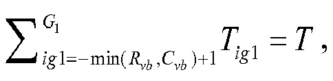
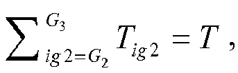

- In an example, the bit sequence in Mvb can be arranged as

- It is to be noted that the above steps can be, but not limited to be, performed by a base station or a terminal.
- With the description of the above embodiments, it will be apparent to those skilled in the art that the method according to the above embodiments can be implemented by means of software plus a necessary general-purpose hardware platform. Of course it can be implemented in hardware, but in many cases the former is the optimal implementation. Based on this understanding, the technical solution of the present disclosure in essence, or parts thereof contributive to the prior art, can be embodied in the form of a software product. The computer software product can be stored in a storage medium (e.g., ROM/RAM, magnetic disk, or optical disc) and includes instructions for causing a terminal device (which may be a mobile phone, a computer, a server, or a network device, etc.) to perform the method described in the various embodiments of the present disclosure.
- According to an embodiment of the present disclosure, an apparatus for sequence determination is also provided. The apparatus can be applied in a first station for implementing the above embodiments and examples (details thereof will be omitted here). As used hereinafter, the term "module" can be software, hardware, or a combination thereof, capable of performing a predetermined function. While the apparatuses to be described in the following embodiments can be implemented in software, it can be contemplated that they can also be implemented in hardware or a combination of software and hardware.
-
Fig. 3 is a block diagram showing a structure of an apparatus for sequence determination according to an embodiment of the present disclosure. As shown inFig. 3 , the apparatus includes: - a
permuting module 32 configured to map a first bit sequence having a length of K bits to a specified position based on M_index to obtain a second bit sequence; - an
encoding module 34 coupled to theabove permuting module 32 and configured to apply Polar encoding to the second bit sequence to obtain a Polar encoded bit sequence; and - a selecting
module 36 coupled to theabove encoding module 34 and configured to select T bits based on the Polar encoded bit sequence as a bit sequence to be transmitted, where K and T are both non-negative integers and K≤T. - With the above apparatus, a first bit sequence having a length of K bits is mapped to a specified position based on M_index to obtain a second bit sequence. Polar encoding is applied to the second bit sequence to obtain a Polar encoded bit sequence. T bits are selected based on the Polar encoded bit sequence as a bit sequence to be transmitted. That is, the present disclosure provides a method for determining a bit sequence to be transmitted, capable of solving the problem in the related art associated with lack of a sequence determination scheme in the 5G New RAT.
- In an embodiment of the present disclosure, the above apparatus may further include: a first transform module coupled to the
above permuting module 32 and configured to apply a first predetermined transform to a first index matrix to obtain a second index matrix and obtain M_index based on the second index matrix. The first predetermined transform includes row permutation or column permutation. That is, in the Polar encoding process, the same transform pattern is applied to one dimension of the first index matrix, such that only the other dimension of the first index matrix needs to be changed when a mother code length changes. Thus, the hardware can be reused in the implementation of Polar codes, thereby solving the problem in the related art associated with incapability of hardware reuse in the Polar encoding process. - In an embodiment of the present disclosure, the apparatus may further include: a second transform module configured to form a first bit sequence matrix from the Polar encoded bit sequence, and apply a second predetermined transform to the first bit sequence matrix to obtain a second bit sequence matrix. The second predetermined transform includes row permutation or column permutation. The selecting module is further configured to select T bits based on the second bit sequence matrix as the bit sequence to be transmitted. That is, the same transform pattern is applied to one dimension of the first index matrix, such that only the other dimension of the first index matrix needs to be changed when a mother code length changes. Thus, the hardware can be further reused in the implementation of Polar codes, thereby further solving the problem in the related art associated with incapability of hardware reuse in the Polar encoding process.
- It is to be noted that the above apparatus may further include a storage module coupled to the above first transform module and configured to store the second bit sequence matrix.
- It is to be noted that the above storage module can be, but not limited to, a buffer or any other memory, such as an internal memory or any other logic entity.
- It is to be noted that the above first index matrix can be, but not limited to, a two dimensional, three dimensional or multi-dimensional matrix. In an example where the above first index matrix is a two dimensional matrix, the above first predetermined transform can be embodied such that a row transform pattern or a column transform pattern for the first index matrix is the same.
- In an example where the above first index matrix is a two dimensional matrix, in an embodiment of the present disclosure, the second index matrix is Mre, which is a matrix of Rre rows and Cre columns. The first index matrix is Mor, which is:


- It is to be noted that when Rre is constant, Cre is a minimum value satisfying Rre×Cre≥N; or when Cre is constant, Rre is a minimum value satisfying Rre×Cre≥N.
- It is to be noted that the above first transform module is further configured to obtain the second index matrix according to at least one of: the i-th column of Mre being obtained from the π1(i)-th column of Mor by means of column permutation, where 0≤i≤Cre-1, 0≤π1(i)≤Cre-1, Rre×Cre≥N, and i and π1(i) are both non-negative integers; or the j-th row of Mre being obtained from the π2(j)-th row of Mor, where 0≤j≤Rre-1, 0≤π2(j)<Rre-1, Rre×Cre≥N, and j and π2(j) are both non-negative integers.
- It is to be noted that the above π1(i) can be obtained according to at least one of:
- Scheme 1: π1(i)=BRO(i) where BRO() denotes a bit reverse ordering operation which includes: converting a decimal number i into a first binary number (Bn1-1,Bn1-2,...,B0), reversing the first binary number to obtain a second binary number (B0,B1,...,Bn1-1) and converting the second binary number into a decimal number π1(i), where n1=log2(Cre) and 0≤i≤Cre-1;
- Scheme 2: π1(i)={S1,S2,S3}, where S1={0,1,...,i1-1}, S2={i2,i3,i2+1,i3+1,...,i4,i5}, and S3 is a set of elements in {0,1,..., Cre-1} other than those included in S1 and S2, where Cre/8≤i1≤i2≤Cre/3, i2≤i4≤i3≤2Cre/3, i3≤i5≤Cre-1, i1, i2, i3, i4 and i5 are all non-negative integers, and an intersection of any two of S1, S2 and S3 is null; or
- Scheme 3: π1(i)={I}, where {I} is a sequence obtained by organizing numerical results of applying a function f(r) to column indices r of Mor in ascending or descending order, where 0≤r≤Cre-1.
- The above three schemes will be explained with reference to the following examples.
- For Scheme 1, if Cre =8, i=6, then n1=log2(8)=3. i=6 is converted into a binary number (B2,B1,B0)=(1,1,0). The binary number (B2,B1,B0)=(1,1,0) is reversed to obtain (B0,B1,B2)=(0,1,1). (B0,B1,B2)=(0,1,1) is then converted into a decimal number π1(i)=3.
- For Scheme 2, if Cre=8, i1=2, i2=2, i3=4, i4=3 and i5=5, then S1={0,1}, S2={2,4,3,5}, S3={6,7}, and π1(i)={0,1,2,4,3,5,6,7}.
- For Scheme 3, Cre=8, {f(0),...,f(7)}={0,1,1.18,2.18,1.41,2.41,2.60,3.60}. f(0),..., f(7) is organized in ascending order to obtain π1(i)={1,2,3,5,4,6,7,8}.
- It is to be noted that f(r) includes at least one of:


(Let the initial value f 1 (r) = 2/σ 2, where σ2 is the variance of noise, Cre=8, σ2=0. f 1 (r) is substituted into the iteration equation to obtain f 2 (r), which is then substituted into the iteration equation to obtain f 4 (r), and so on, until f 8 (r) is calculated, where f(r)= f 8 (r), 0≤r≤Cre-1, {f(0),...,f(7)}={0.04,0.41,0.61,3.29,1.00,4.56,5.78,16.00}); or
initializing a function value corresponding to r as f 1 (r), and obtaining a function value for each element

(Let f 1 (r) =0.5 and Cre=8. f 1 (r) is substituted into the iteration equation to obtain f 2 (r), which is then substituted into the iteration equation to obtain f 4 (r), and so on, until f 8 (r) is calculated, where f(r)= f 8 (r), 0≤i≤Cre-1, {f(0),...,f(7)}={0.008,0.152,0.221,0.682,0.313,0.779,0.850,0.991}). - It is to be noted that the above π2(j) can be obtained according to at least one of:
- π2(j)=BRO(j), where BRO() denotes a bit reverse ordering operation which includes: converting a decimal number j into a third binary number (Bn2-1,Bn2-2,...,B0), reversing the third binary number to obtain a fourth binary number (B0,B1,...,Bn2-1) and converting the fourth binary number into a decimal number π2(j), where n2=log2(Rre) and 0≤j≤Rre-1;
- π2(j)={S4,S5,S6}, where S4={0,1,...,j1-1}, S5={j2,j3,j2+l,j3+1,...,j4,j5}, and S6 is a set of elements in {0,1,..., Rre-1} other than those included in S4 and S5, where Rre/8≤j1≤j2≤Rre/3, j2≤j4≤j3≤2 Rre/3, j3≤j5≤Rre-1, j1, j2, j3, j4 and j5 are all non-negative integers, and an intersection of any two of S4, S5 and S6 is null; or
- π2(i)={J}, where {J} is a sequence obtained by organizing numerical results of applying a function f(s) to row indices s of Mor in ascending or descending order, where 0≤s≤Rre-1.
- It is to be noted that f(s) includes at least one of:
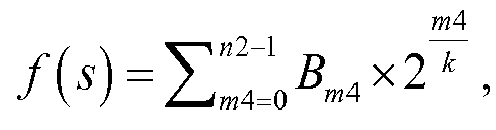
initializing a function value corresponding to s as f 1 (s), and obtaining a function value for each element

initializing a function value corresponding to s as f 1 (s), and obtaining a function value for each element

- It is to be noted that, for explanations for the above π2(j), reference can be made to π1(i).
- It is to be noted that the above first bit sequence matrix can be, but not limited to, a two dimensional, three dimensional or multi-dimensional matrix. In an example where the above first bit sequence matrix is a two dimensional matrix, the above second predetermined transform can be embodied such that a row transform pattern or a column transform pattern for the first bit sequence matrix is the same.
- It is to be noted that the first bit sequence matrix is Mog. The second bit sequence matrix is Mvb, which is a matrix of Rvb rows and Cvb columns. Mog is:

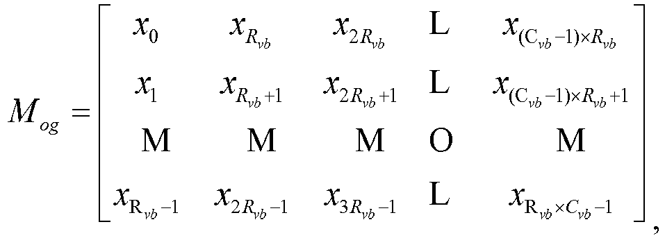
- It is to be noted that when Rvb is constant, Cvb is a minimum value satisfying Rvb×Cvb≥N; or when Cvb is constant, Rvb is a minimum value satisfying Rvb×Cvb≥N.
- It is to be noted that the above second transform module can further be configured to obtain the second bit sequence matrix according to at least one of: the g-th column of Mvb being obtained from the π3(g)-th column of Mog by means of column permutation, where 0≤g≤Cvb-1, 0≤π3(g)≤Cvb-1, Rvb×Cvb≥N, and g and π3(g) are both non-negative integers; or the h-th row of Mvb being obtained from the π4(h)-th row of Mog by means of row permutation, where 0≤h≤Rvb-1, 0≤π4(h)≤Rvb-1, Rvb×Cvb≥N, and h and π4(h) are both non-negative integers.
- It is to be noted that π3(g) can be obtained according to at least one of:
- π3(g)=BRO(g), where BRO() denotes a bit reverse ordering operation which includes: converting a decimal number g into a fifth binary number (Bn3-1,Bn3-2,... ,B0), reversing the fifth binary number to obtain a sixth binary number (B0,B11,...,Bn3-1) and converting the sixth binary number into a decimal number π3(g), where n3=log2(Cvb) and 0≤g≤Cvb-1;
- π3(g)={S1,S2,S3}, where S1={0,1,...,g1-1}, S2={g2,g3,g2+1,g3+1,...,g4,g5}, and S3 is a set of elements in {0,1,..., Cvb-1} other than those included in S1 and S2, where Cvb/8≤g1≤g2≤Cvb/3, g2≤g4≤g3≤2Cvb/3, g3≤g5≤Cvb-1, g1, g2, g3, g4 and g5 are all non-negative integers, and an intersection of any two of S1, S2 and S3 is null;
- π3(g)={G}, where {G} is a sequence obtained by organizing numerical results of applying a function f(α) to column indices α of Mog in ascending or descending order, where 0≤α≤Cvb-1; π3(g)={Q1,Q2,Q3}, where Q2={q1,q2,q1+1,q2+1,...,q3,q4}, 0≤q1<q3≤(Cvb-1)/2, 0≤q2<q4≤(Cvb-1)/2, q1, q2, q3, q4 and q5 are all non-negative integers, Q1 and Q3 are other elements in a difference set between {0,1, ..., Cvb-1} and Q2, and an intersection of any two of Q1, Q2 and Q3 is null;
- π3(g) being different from a predefined sequence V1 in nV1 positions, where V1={0,1,2,3,4,5,6,7,8,9,10,11,12,16,13,17,14,18,15,19,20,24,21,22,25,26,28,23,27,29,30,31}, 0≤nV1≤23; or
- π3(g) being different from a predefined sequence V2 in nV2 positions, where V2={0, 1, 2, 4, 3, 5, 6, 7, 8, 16, 9, 17, 10, 18, 11, 19, 12, 20, 13, 21, 14, 22, 15, 23, 24, 25, 26, 28, 27, 29, 30, 31}, 0≤nV2≤3.
- It is to be noted that f(α) includes at least one of:


- It is to be noted that π4(h) can be obtained according to at least one of:
- π4(H)=BKOP(h) where BRO() denotes a bit reverse ordering operation which includes: converting a decimal number h into a seventh binary number (Bn4-1,Bn4-2,...,B0), reversing the seventh binary number to obtain an eighth binary number (B0,B1,...,Bn4-1) and converting the eighth binary number into a decimal number π4(h), where n4=log2(Rvb) and 0≤h≤Rvb-1;
- π4(h)={S4,S5,S6}, where S4={0,1,...,h1-1}, S5={h2,h3,h2+1,h3+1,...,h4,h5}, and S6 is a set of elements in {0,1,..., Rvb-1} other than those included in S4 and S5, where Rvb/8≤h1≤h2≤Rvb/3, h2≤h4≤h3≤2Rvb/3, h3≤h5≤Rvb-1, h1, h2, h3, h4 and h5 are all non-negative integers, and an intersection of any two of S4, S5 and S6 is null;
- π4(h)={H}, where {H} is a sequence obtained by organizing numerical results of applying a function f(β) to row indices β of Mog in ascending or descending order, where 0≤β≤Rvb-1;
- π4(h)={O1,O2,O3}, where O2={o1,o2,o1+1,o2+1,...,o3,o4}, 0≤o1≤o3≤(Rvb-1)/2, 0≤o2<o4≤(Rvb-1)/2, o1, o2, o3, o4 and o5 are all non-negative integers, O1 and O3 are other elements in a difference set between {0, 1, ..., Rvb-1} and O2, and an intersection of any two of O1, O2 and O3 is null;
- π4(h) being different from a predefined sequence VV1 in n VV1 positions, where VV1={0,1,2,3,4,5,6,7,8,9,10,11,12,16,13,17,14,18,15,19,20,24,21,22,25,26,28,23,27,29,30,31}, 0≤nVV1≤23; or
- π4(h) being different from a predefined sequence VV2 in nVV2 positions, where VV2={0, 1, 2, 4, 3, 5, 6, 7, 8, 16, 9, 17, 10, 18, 11, 19, 12, 20, 13, 21, 14, 22, 15, 23, 24, 25, 26, 28, 27, 29, 30, 31}, 0≤nVV2≤3.
- It is to be noted that f(β) includes at least one of:


- It is to be noted that, for explanations for π3(g) and π4(h), reference can be made to π1(i) and descriptions thereof will be omitted here.
- In an embodiment of the present disclosure, the above first transform module can further be configured to select a predetermined number of indices based on Mre row by row, column by column or diagonal by diagonal, as M_index.
- It is to be noted that the operation of selecting the predetermined number of indices from Mre column by column includes: selecting Kp indices from the p-th column of Mre, where


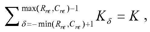
- It is to be noted that the operation of selecting the predetermined number of indices from Mre column by column includes at least one of: selecting Kic1 indices from the 1st, 2nd, ..., C1-th columns of Mre, where
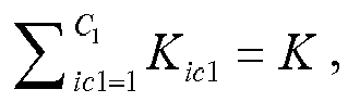


- It is to be noted that the operation of selecting the predetermined number of indices from Mre row by row includes at least one of: selecting Kir1 indices from the 1st, 2nd, ..., R1-th rows of Mre, where
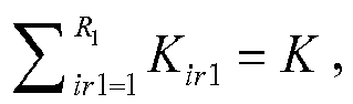


- It is to be noted that the operation of selecting the predetermined number of indices from Mre diagonal by diagonal includes at least one of: selecting Kid1 indices from the (-min(Rre,Cre)+1)-th, (-min(Rre,Cre)+2)-th, ..., D1-th diagonals of Mre, where

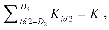

- It is to be noted that, when the predetermined number of indices are selected from Mre row by row, column by column or diagonal by diagonal, each index corresponding to a non-transmitted bit sequence in a second bit sequence matrix is skipped. The second bit sequence matrix is obtained from a first bit sequence matrix by using a second predetermined transform. The first bit sequence matrix is formed from the Polar encoded bit sequence. The second predetermined transform includes row permutation or column permutation.
- It is to be noted that the above selecting
module 36 can further be configured to select T bits based on the second bit sequence matrix row by row, column by column or diagonal by diagonal, as the bit sequence to be transmitted. - It is to be noted that the above selecting
module 36 can further be configured to select T bits from the second bit sequence matrix row by row, column by column or diagonal by diagonal, from a starting position t in the second bit sequence matrix. When the selection reaches the first or last bit in the second bit sequence matrix, it continues with the last or first bit in the second bit sequence matrix, where 1≤t≤Rvb×Cvb. - It is to be noted that the above selecting
module 36 can further be configured to select the 1st to T-th bits or the (N-T+1)-th to N-th bits from the second bit sequence matrix column by column, when T is smaller than or equal to a length N of the Polar encoded bit sequence; select the 1st to T-th bits or the (N-T+1)-th to N-th bits from the second bit sequence matrix row by row, when T is smaller than or equal to the length N of the Polar encoded bit sequence; select the 1st to T-th bits or the (N-T+1)-th to N-th bits from the second bit sequence matrix diagonal by diagonal, when T is smaller than or equal to the length N of the Polar encoded bit sequence; select, when T is larger than the length N of the Polar encoded bit sequence, T bits row by row, column by column or diagonal by diagonal, from the t-th bit in the second bit sequence matrix. When the selection reaches the first or last bit in the second bit sequence matrix, it continues with the last or first bit in the second bit sequence matrix, where 1≤t≤Rvb×Cvb and N is a non-negative integer. It is to be noted that the operation of selecting T bits from the second bit sequence matrix column by column includes at least one of: selecting Tie1 bits from the 1st, 2nd, ..., E1-th columns, where


- It is to be noted that the operation of selecting T bits from the second bit sequence matrix row by row includes at least one of: selecting Tif1 bits from the 1st, 2nd, ..., F1-th rows, where
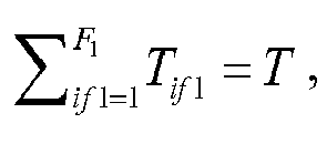


- It is to be noted that the operation of selecting T bits from the second bit sequence matrix diagonal by diagonal includes at least one of: selecting Tig1 bits from the (-min(Rvb,Cvb)+1)-th, (-min(Rvb,Cvb)+2)-th, ..., G1-th diagonals, where

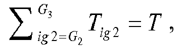

- It is to be noted that the above apparatus can be, but not limited to be, provided in a terminal or a network device such as a base station.
- It should be noted that each of the above-described modules can be implemented by means of software or hardware, and the latter can be implemented in, but not limited to, the following manner: the above-described modules can be located at the same processor, or can be distributed over a plurality of processors in any combination.
- Embodiment 3 of the present disclosure provides a device.
Fig. 4 is a block diagram showing a structure of a device according to Embodiment 3 of the present disclosure. AS shown inFig. 4 , the device includes: - a
processor 42 configured to: map a first bit sequence having a length of K bits to a specified position based on M_index to obtain a second bit sequence; apply Polar encoding to the second bit sequence to obtain a Polar encoded bit sequence; and select T bits based on the Polar encoded bit sequence as a bit sequence to be transmitted, where K and T are both non-negative integers and K≤T, and - a
memory 44 coupled to theprocessor 42. - With the above device, a first bit sequence having a length of K bits is mapped to a specified position based on M_index to obtain a second bit sequence. Polar encoding is applied to the second bit sequence to obtain a Polar encoded bit sequence. T bits are selected based on the Polar encoded bit sequence as a bit sequence to be transmitted. That is, the present disclosure provides a method for determining a bit sequence to be transmitted, capable of solving the problem in the related art associated with lack of a sequence determination scheme in the 5G New RAT.
- In an embodiment of the present disclosure, the
above processor 42 can further be configured to: apply a first predetermined transform to a first index matrix to obtain a second index matrix; and obtain M_index based on the second index matrix. The first predetermined transform includes row permutation or column permutation. That is, in the Polar encoding process, the same transform pattern is applied to one dimension of the first index matrix, such that only the other dimension of the first index matrix needs to be changed when a mother code length changes. - Thus, the hardware can be reused in the implementation of Polar codes, thereby solving the problem in the related art associated with incapability of hardware reuse in the Polar encoding process.
- In an embodiment of the present disclosure, the
above processor 42 can further be configured to: write the Polar encoded bit sequence into a first bit sequence matrix; and apply a second predetermined transform to the first bit sequence matrix to obtain a second bit sequence matrix. - The second predetermined transform includes row permutation or column permutation. A selecting module is configured to select T bits based on the second bit sequence matrix as the bit sequence to be transmitted. That is, the same transform pattern is applied to one dimension of the first index matrix, such that only the other dimension of the first index matrix needs to be changed when a mother code length changes. Thus, the hardware can be further reused in the implementation of Polar codes, thereby further solving the problem in the related art associated with incapability of hardware reuse in the Polar encoding process.
- It is to be noted that the above storage module can be configured to store the above second bit sequence matrix. The above storage module can be, but not limited to, a buffer or any other memory, such as an internal memory or any other logic entity.
- It is to be noted that the above first index matrix can be, but not limited to, a two dimensional, three dimensional or multi-dimensional matrix. In an example where the above first index matrix is a two dimensional matrix, the above first predetermined transform can be embodied such that a row transform pattern or a column transform pattern for the first index matrix is the same.
- In an example where the above first index matrix is a two dimensional matrix, in an embodiment of the present disclosure, the second index matrix is Mre, which is a matrix of Rre rows and Cre columns. The first index matrix is Mor, which is:


- It is to be noted that when Rre is constant, Cre is a minimum value satisfying Rre×Cre≥N; or when Cre is constant, Rre is a minimum value satisfying Rre×Cre≥N.
- It is to be noted that the
above processor 42 can further be configured to obtain the second index matrix according to at least one of: the i-th column of Mre being obtained from the π1(i)-th column of Mor by means of column permutation, where 0≤i≤Cre-1, 0≤π1(i)≤Cre-1, Rre×Cre≥N, and i and π1(i) are both non-negative integers; or the j-th row of Mre being obtained from the π2(j)-th row of Mor, where 0≤j≤Rre-1, 0≤π2(j)≤Rre-1, Rre×Cre≥N, and j and π2(j) are both non-negative integers. - It is to be noted that the above π1(i) can be obtained according to at least one of:
- Scheme 1: π1(i)=BRO(i) where BRO() denotes a bit reverse ordering operation which includes: converting a decimal number i into a first binary number (Bn1-1,Bn1-2,...,B0), reversing the first binary number to obtain a second binary number (B0,B1,..,Bn1-1) and converting the second binary number into a decimal number π1(i), where n1=log2(Cre) and 0≤i≤Cre-1;
- Scheme 2: π1(i)={S1,S2,S3}, where S1={0,1,...,i1-1}, S2={i2,i3,i2+1,i3+1,...,i4,i5}, and S3 is a set of elements in {0,1,..., Cre-1} other than those included in S1 and S2, where Cre/8≤i1≤i2≤Cre/3, i2≤i4≤i3≤2Cre/3, i3≤i5≤Cre-1, i1, i2, i3, i4 and i5 are all non-negative integers, and an intersection of any two of S1, S2 and S3 is null; or
- Scheme 3: π1(i)={1}, where {I} is a sequence obtained by organizing numerical results of applying a function f(r) to column indices r of Mor in ascending or descending order, where 0≤r≤Cre-1.
- The above three schemes will be explained with reference to the following examples.
- For Scheme 1, if Cre =8, i=6, then n1=log2(8)=3. i=6 is converted into a binary number (B2,B1,B0)=(1,1,0). The binary number (B2,B1,B0)=(1,1,0) is reversed to obtain (B0,B1,B2)=(0,1,1). (B0,B1,B2)=(0,1,1) is then converted into a decimal number π1(i)=3.
- For Scheme 2, if Cre=8, i1=2, i2=2, i3=4, i4=3 and i5=5, then S1={0,1}, S2={2,4,3,5}, S3={6,7}, and π1(i)={0,1,2,4,3,5,6,7}.
- For Scheme 3, Cre=8, {f(0),...,f(7)}={0,1,1.18,2.18,1.41,2.41,2.60,3.60}. f(0),..., f(7) is organized in ascending order to obtain π1(i)={1,2,3,5,4,6,7,8}.
- It is to be noted that f(r) includes at least one of:


(Let the initial value

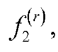


initializing a function value corresponding to r as

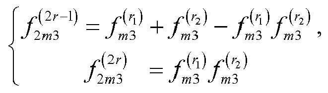

(Let


- It is to be noted that the above π2(j) can be obtained according to at least one of:
- π2(j)=BRO(j), where BRO() denotes a bit reverse ordering operation which includes: converting a decimal number j into a third binary number (Bn2-1,Bn2-2,...,B0), reversing the third binary number to obtain a fourth binary number (B0,B1,... ,Bn2-1) and converting the fourth binary number into a decimal number π2(j), where n2=log2(Rre) and 0≤j≤Rre-1;
- π2(j)={S4,S5,S6}, where S4={0,1,...,j1-1}, SS={j2,j3,j2+1,j3+1,...,j4,j5}, and S6 is a set of elements in {0,1,..., Rre-1} other than those included in S4 and S5, where Rre/8≤j1≤j2≤Rre/3, j2≤j4≤j3≤2 Rre/3, j3≤j5≤Rre-1, j1, j2, j3, j4 and j5 are all non-negative integers, and an intersection of any two of S4, S5 and S6 is null; or
- π2(i)={J}, where {J} is a sequence obtained by organizing numerical results of applying a function f(s) to row indices s of Mor in ascending or descending order, where 0≤s≤Rre-1.
- It is to be noted that f(s) includes at least one of:

initializing a function value corresponding to s as


- It is to be noted that, for explanations for the above π2(j), reference can be made to π1(i).
- It is to be noted that the above first bit sequence matrix can be, but not limited to, a two dimensional, three dimensional or multi-dimensional matrix. In an example where the above first bit sequence matrix is a two dimensional matrix, the above second predetermined transform can be embodied such that a row transform pattern or a column transform pattern for the first bit sequence matrix is the same.
- It is to be noted that the first bit sequence matrix is Mog. The second bit sequence matrix is Mvb, which is a matrix of Rvb rows and Cvb columns. Mog is:


- It is to be noted that when Rvb is constant, Cvb is a minimum value satisfying Rvb×Cvb≥N; or when Cvb is constant, Rvb is a minimum value satisfying Rvb×Cvb≥N.
- It is to be noted that the
above processor 42 can further be configured to obtain the second bit sequence matrix according to at least one of: the g-th column of Mvb being obtained from the π3(g)-th column of Mog by means of column permutation, where 0≤g≤Cvb-1, 0≤π3(g)≤Cvb-1, Rvb×Cvb≥N, and g and π3(g) are both non-negative integers; or the h-th row of Mvb being obtained from the π4(h)-th row of Mog by means of row permutation, where 0≤h≤Rvb-1, 0≤π4(h)≤Rvb-1, Rvb×Cvb≥N, and h and π4(h) are both non-negative integers. - It is to be noted that π3(g) can be obtained according to at least one of:
- π3(g)=BRO(g), where BRO() denotes a bit reverse ordering operation which includes: converting a decimal number g into a fifth binary number (Bn3-1,Bn3-2....,B0), reversing the fifth binary number to obtain a sixth binary number (B0,B11,...,Bn3-1) and converting the sixth binary number into a decimal number π3(g), where n3=log2(Cvb) and 0≤g≤Cvb-1;
- π3(g)={S1,S2,S3}, where S1={0,1,...,g1-1}, S2={g2,g3,g2+1,g3+1,...,g4,g5}, and S3 is a set of elements in {0,1,..., Cvb-1} other than those included in S1 and S2, where Cvb/8≤g1≤g2≤Cvb/3, g2≤g4≤g3≤2Cvb/3, g3≤g5≤Cvb-1, g1, g2, g3, g4 and g5 are all non-negative integers, and an intersection of any two of S1, S2 and S3 is null;
- π3(g)={G}, where {G} is a sequence obtained by organizing numerical results of applying a function f(α) to column indices α of Mog in ascending or descending order, where 0≤α≤Cvb-1; π3(g)={Q1,Q2,Q3}, where Q2={q1,q2,q1+1q2+1,...,q3,q4}, 0≤q1<q3≤(Cvb-1)/2,
- 0≤q2≤q4≤(Cvb-1)/2, q1, q2, q3, q4 and q5 are all non-negative integers, Q1 and Q3 are other elements in a difference set between {0,1, ..., Cvb-1} and Q2, and an intersection of any two of Q1, Q2 and Q3 is null;
- π3(g) being different from a predefined sequence V1 in nV1 positions, where V1={0,1,2,3,4,5,6,7,8,9,10,11,12,16,13,17,14,18,15,19,20,24,21,22,25,26,28,23, 27,29,30,31}, 0≤nV1≤23; or
- π3(g) being different from a predefined sequence V2 in nV2 positions, where V2={0, 1, 2, 4, 3, 5, 6, 7, 8, 16, 9, 17, 10, 18, 11, 19, 12, 20, 13, 21, 14, 22, 15, 23, 24, 25, 26, 28, 27, 29, 30, 31}, 0≤nV2≤3.
- It is to be noted that f(α) includes at least one of:

initializing a function value corresponding to α as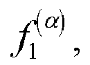


initializing a function value corresponding to s as


1≤m8≤n3, and α1, α2, 2α and 2α-1 are all integers larger than or equal to 0 and smaller than or equal to Cvb-1. - It is to be noted that π4(h) can be obtained according to at least one of:
- π4(h)=BRO(h) where BRO() denotes a bit reverse ordering operation which includes: converting a decimal number h into a seventh binary number (Bn4-1,Bn4-2,...,B0), reversing the seventh binary number to obtain an eighth binary number (B0,B1,...,Bn4-1) and converting the eighth binary number into a decimal number π4(h), where n4=log2(Rvb) and 0≤h≤Rvb-1;
- π4(h)={S4,S5,S6}, where S4={0,1,...,h1-1}, S5={h2,h3,h2+1,h3+1,...,h4,h5}, and S6 is a set of elements in {0,1,..., Rvb-1} other than those included in S4 and S5, where Rvb/8≤h1≤h2≤Rvb/3, h2≤h4≤h3≤2Rvb/3, h3≤h5≤Rvb-1, h1, h2, h3, h4 and h5 are all non-negative integers, and an intersection of any two of S4, S5 and S6 is null;
- π4(h)={H}, where {H} is a sequence obtained by organizing numerical results of applying a function f(β) to row indices β of Mog in ascending or descending order, where 0≤β≤Rvb-1;
- π4(h)={O1,O2,O3}, where O2={o1,o2,o1+1,o2+1,...,o3,o4}, 0≤o1<o3≤(Rvb-1)/2, 0≤o2<o4≤(Rvb-1)/2, o1, o2, o3, o4 and o5 are all non-negative integers, O1 and O3 are other elements in a difference set between {0,1, ..., Rvb-1} and O2, and an intersection of any two of O1, O2 and O3 is null;
- π4(h) being different from a predefined sequence VV1 in n VV1 positions, where W1={0,1,2,3,4,5,6,7,8,9,10,11,12,16,13,17,14,18,15,19,20,24,21,22,25,26,28,23,27,29,30,31}, 0≤nVV1≤23; or
- π4(h) being different from a predefined sequence VV2 in nVV2 positions, where VV2={0, 1, 2, 4, 3, 5, 6, 7, 8, 16, 9, 17, 10, 18, 11, 19, 12, 20, 13, 21, 14, 22, 15, 23, 24, 25, 26, 28, 27, 29, 30, 31}, 0≤nVV2≤3.
- It is to be noted that f(β) includes at least one of:

initializing a function value corresponding to β as


initializing a function value corresponding to β as


- It is to be noted that, for explanations for π3(g) and π4(h), reference can be made to π1(i) and descriptions thereof will be omitted here.
- In an embodiment of the present disclosure, the above first transform module can further be configured to select a predetermined number of indices based on Mre row by row, column by column or diagonal by diagonal, as M_index.
- It is to be noted that the operation of selecting the predetermined number of indices from Mre column by column includes: selecting Kp indices from the p-th column of Mre, where


- It is to be noted that the operation of selecting the predetermined number of indices from Mre column by column includes at least one of: selecting Kic1 indices from the 1st, 2nd, ..., C1-th columns of Mre, where


- It is to be noted that the operation of selecting the predetermined number of indices from Mre row by row includes at least one of: selecting Kir1 indices from the 1st, 2nd, ..., R1-th rows of Mre, where


- It is to be noted that the operation of selecting the predetermined number of indices from Mre diagonal by diagonal includes at least one of: selecting Kid1 indices from the (-min(Rre,Cre)+1)-th, (-min(Rre,Cre)+2)-th, ..., D1-th diagonals of Mre, where


- It is to be noted that, when the predetermined number of indices are selected from Mre row by row, column by column or diagonal by diagonal, each index corresponding to a non-transmitted bit sequence in a second bit sequence matrix is skipped. The second bit sequence matrix is obtained from a first bit sequence matrix by using a second predetermined transform. The first bit sequence matrix is formed from the Polar encoded bit sequence. The second predetermined transform includes row permutation or column permutation.
- It is to be noted that the
above processor 42 can further be configured to select T bits based on the second bit sequence matrix row by row, column by column or diagonal by diagonal, as the bit sequence to be transmitted. - It is to be noted that the
above processor 42 can further be configured to select T bits based on the second bit sequence matrix row by row, column by column or diagonal by diagonal, from a starting position t in the second bit sequence matrix. When the selection reaches the first or last bit in the second bit sequence matrix, it continues with the last or first bit in the second bit sequence matrix, where 1≤t≤Rb×Cvb. - It is to be noted that the
above processor 42 can further be configured to select the 1st to T-th bits or the (N-T+1)-th to N-th bits from the second bit sequence matrix column by column, when T is smaller than or equal to a length N of the Polar encoded bit sequence; select the 1st to T-th bits or the (N-T+1)-th to N-th bits from the second bit sequence matrix row by row, when T is smaller than or equal to the length N of the Polar encoded bit sequence; select the 1st to T-th bits or the (N-T+1)-th to N-th bits from the second bit sequence matrix diagonal by diagonal, when T is smaller than or equal to the length N of the Polar encoded bit sequence; select, when T is larger than the length N of the Polar encoded bit sequence, T bits row by row, column by column or diagonal by diagonal, from the t-th bit in the second bit sequence matrix. When the selection reaches the first or last bit in the second bit sequence matrix, it continues with the last or first bit in the second bit sequence matrix, where 1≤t≤Rvb×Cvb and N is a non-negative integer. - It is to be noted that the operation of selecting T bits from the second bit sequence matrix column by column includes at least one of: selecting Tie1 bits from the 1st, 2nd, ..., E1-th columns , where


- It is to be noted that the operation of selecting T bits from the second bit sequence matrix row by row includes at least one of: selecting Tif1 bits from the 1st, 2nd, ..., F1-th rows , where

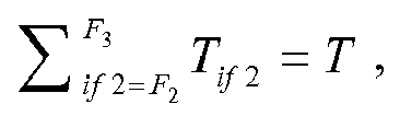

- It is to be noted that the operation of selecting T bits from the second bit sequence matrix diagonal by diagonal includes at least one of: selecting Tig1 bits from the (-min(Rvb,Cvb)+1)-th, (-min(Rvb,Cvb)+2)-th, ..., G1-th diagonals , where
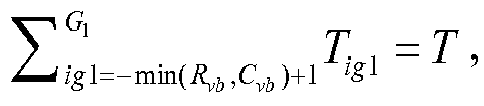


- It is to be noted that the above device can be, but not limited to a terminal or a network device such as a base station.
- According to an embodiment of the present disclosure, a storage medium is also provided. The storage medium stores a program which, when executed, performs any of the above described methods.
- According to an embodiment of the present disclosure, the above storage medium can be configured to store program codes for performing the steps of the method described above in connection with Embodiment 1.
- According to an embodiment of the present disclosure, the above storage medium may include, but not limited to, a USB disk, a Read-Only Memory (ROM), a Random Access Memory (RAM), a mobile hard disk, a magnetic disk, an optical disc, or other mediums capable of storing program codes.
- According to an embodiment of the present disclosure, a processor is provided. The processor is configured to execute a program for performing the steps of any of the above described methods. According to an embodiment of the present disclosure, the above program is configured to perform the steps of the method described above in connection with Embodiment 1.
- For detailed examples of this embodiment, reference can be made to those examples described in connection with the above and optional embodiments and description thereof will be omitted here.
- In the following, the present disclosure will be further explained with reference to the examples, such that the present disclosure can be better understood.
- The following numerical values are provided for the purpose of illustration. For other situations, reference can be made to the following operation steps.
- It is assumed that the number of columns in each of the index matrix Mor, the index matrix Mre, the bit sequence matrix Mvb and the bit sequence matrix Mog is fixed to be 32. The length of the first bit sequence is K=40 and the length of the bit sequence to be transmitted is T=100. Polar encoding having a mother code length of 128 is applied. In particular, the encoding process is as follows.
- (1) The number Rre of rows of the index matrix Mre needs to be selected as a minimum value satisfying Rre×Cre≥N. According to the above assumptions, Cre=32 and N=128, then Rre=4. It is assumed that the indices in the index matrix Mog are arranged row by row:

- (2) If the index matrix Mre is obtained from the index matrix Mor by means of column permutation, e.g., by mapping the π1(i)-th column of the index matrix Mor to the i-th column of the index matrix Mre by means of column permutation. The indices in π1(i) are arranged in ascending order of numerical results obtained based on a function. If the function is expressed as

- (3) The bit sequence matrix Mvb is obtained from the bit sequence matrix Mog by means of column permutation, e.g., by mapping the π2(i)-th column of the bit sequence matrix Mog to the i-th column of the bit sequence matrix Mvb by means of column permutation. Here, π2(i)=BRO(i), and the column permutation pattern is π2(i)={0,16,8,24,4,20,12,28,2,18,10,26,6,22,14,30,1,17,9,25,5,21,13,29,3,19,11,27,7,23,15,31}. Accordingly, the column having an index of 0 in the bit sequence matrix Mog is the column having an index of 0 in the bit sequence matrix Mvb, the column having an index of 16 in the bit sequence matrix Mog is the column having an index of 1 in the bit sequence matrix Mvb, the column having an index of 8 in the bit sequence matrix Mog is the column having an index of 2 in the bit sequence matrix Mvb, and so on.
- (4) The first T=100 bits are selected from the bit sequence matrix Mvb column by column to form a bit sequence to be transmitted, which is {y0,y32,y64,y96,y16,y48,y80,y112,...,y23,y55,y87,y119}.
- (5) K=40 indices in total are selected from the index matrix Mre row by row to form the index sequence M_index. It is to be noted that, during the selection of the indices, each index corresponding to a non-transmitted bit sequence is skipped. That is, the selection is made from the indices corresponding to the bit sequence to be transmitted as outputted from an encoder in the step (4).
- (6) After an input bit sequence having a length of K is mapped to encoder positions indicated by the index sequence M index, Polar encoding can be applied to obtain an encoded bit sequence having a length of N=128. The bits determined in the step (4) are organized into a bit sequence to be transmitted, for transmission from a transmitter.
- It is assumed that the number of columns in each of the index matrix Mor, the index matrix Mre, the bit sequence matrix Mvb and the bit sequence matrix Mog is fixed to be 32. The length of the input bit sequence is K=40 and the length of the bit sequence to be transmitted is T=100. Polar encoding having a mother code length of 128 is applied. In particular, the encoding process is different from Example 1 in that, in the step (4), the last T=100 bits are selected from the bit sequence matrix Mvb column by column to form the bit sequence to be transmitted, which is {y8,y24,y40,y56,y72,y88,y104,y120,..., y15, y31,y47,y63,y79,y95,y111,y127}.
- It is assumed that the number of columns in each of the index matrix Mor, the index matrix Mre, the bit sequence matrix Mvb and the bit sequence matrix Mog is fixed to be 32. The length of the input bit sequence is K=40 and the length of the bit sequence to be transmitted is T=150. Polar encoding having a mother code length of 128 is applied. In particular, the encoding process is different from Example 1 in that, in the step (4), T=130 bits are selected from the bit sequence matrix Mvb row by row, starting from the first element in the bit sequence matrix Mvb. When the selection reaches the last bit y127 in the buffer or in the bit sequence matrix Mvb, it continues with the first bit y0 of the bit sequence matrix Mvb. The resulting bit sequent to be transmitted is {y0,y1,y2,...,y127,y0,y1,y2}.
- It is assumed that the number of columns in each of the index matrix Mor, the index matrix Mre, the bit sequence matrix Mvb and the bit sequence matrix Mog is fixed to be 32. The length of the input bit sequence is K=40 and the length of the bit sequence to be transmitted is T=150. Polar encoding having a mother code length of 128 is applied. In particular, the encoding process is different from Example 3 in that, in the step (4), T=130 bits are selected from the bit sequence matrix Mvb row by row, starting from the last element in the bit sequence matrix Mvb. When the selection reaches the first bit y0 in the buffer or in the bit sequence matrix Mvb, it continues with the last bit y127 of the bit sequence matrix Mvb. The resulting bit sequent to be transmitted is {y0,y1,y2,...,y127,y127,y126,y125}.
- It is assumed that the number of columns in each of the index matrix Mor, the index matrix Mre, the bit sequence matrix Mvb and the bit sequence matrix Mog is fixed to be 32. The length of the input bit sequence is K=40 and the length of the bit sequence to be transmitted is T=100. Polar encoding having a mother code length of 128 is applied. In particular, the encoding process is different from Example 1 in that, the input bit sequence having the length of K=40 is mapped to the encoder positions using Gaussian approximation, density evolution, PW sequence, FRANK sequence, or other schemes. Details of the operations will be omitted here.
- It is assumed that the number of columns in each of the index matrix Mor, the index matrix Mre, the bit sequence matrix Mvb and the bit sequence matrix Mog is fixed to be 32. The length of the input bit sequence is K=40 and the length of the bit sequence to be transmitted is T=100. Polar encoding having a mother code length of 128 is applied. In particular, the encoding process is different from Example 2 in that, the input bit sequence having the length of K=40 is mapped to the encoder positions using Gaussian approximation, density evolution, PW sequence, FRANK sequence, or other schemes. Details of the operations will be omitted here.
- It is assumed that the number of columns in each of the index matrix Mor, the index matrix Mre, the bit sequence matrix Mvb and the bit sequence matrix Mog is fixed to be 32. The length of the input bit sequence is K=40 and the length of the bit sequence to be transmitted is T=130. Polar encoding having a mother code length of 128 is applied. In particular, the encoding process is different from Example 3 in that, the input bit sequence having the length of K=40 is mapped to the encoder positions using Gaussian approximation, density evolution, PW sequence, FRANK sequence, or other schemes. Details of the operations will be omitted here.
- It is assumed that the number of columns in each of the index matrix Mor, the index matrix Mre, the bit sequence matrix Mvb and the bit sequence matrix Mog is fixed to be 32. The length of the input bit sequence is K=40 and the length of the bit sequence to be transmitted is T=130. Polar encoding having a mother code length of 128 is applied. In particular, the encoding process is different from Example 4 in that, the input bit sequence having the length of K=40 is mapped to the encoder positions using Gaussian approximation, density evolution, PW sequence, FRANK sequence, or other schemes. Details of the operations will be omitted here.
- It is assumed that the number of columns in each of the index matrix Mor, the index matrix Mre, the bit sequence matrix Mvb and the bit sequence matrix Mog is fixed to be 32. The length of the input bit sequence is K=40 and the length of the bit sequence to be transmitted is T=100. Polar encoding having a mother code length of 128 is applied. In particular, the encoding process is different from Example 1 in that a different rate matching scheme is used. Details of the operations will be omitted here.
- It is assumed that the number of columns in each of the index matrix Mor, the index matrix Mre, the bit sequence matrix Mvb and the bit sequence matrix Mog is fixed to be 32. The length of the input bit sequence is K=40 and the length of the bit sequence to be transmitted is T=100. Polar encoding having a mother code length of 128 is applied. In particular, the encoding process is different from Example 2 in that a different rate matching scheme is used. Details of the operations will be omitted here.
- It is assumed that the number of columns in each of the index matrix Mor, the index matrix Mre, the bit sequence matrix Mvb and the bit sequence matrix Mog is fixed to be 32. The length of the input bit sequence is K=40 and the length of the bit sequence to be transmitted is T=130. Polar encoding having a mother code length of 128 is applied. In particular, the encoding process is different from Example 3 in that a different rate matching scheme is used. Details of the operations will be omitted here.
- It is assumed that the number of columns in each of the index matrix Mor, the index matrix Mre, the bit sequence matrix Mvb and the bit sequence matrix Mog is fixed to be 32. The length of the input bit sequence is K=40 and the length of the bit sequence to be transmitted is T=130. Polar encoding having a mother code length of 128 is applied. In particular, the encoding process is different from Example 4 in that a different rate matching scheme is used. Details of the operations will be omitted here.
- It can be appreciated by those skilled in the art that the above-described modules or steps of the present disclosure can be implemented by a general purpose computing device, and can be centralized at one single computing device or distributed over a network of multiple computing devices. Optionally, they can be implemented by means of computer executable program codes, which can be stored in a storage device and executed by one or more computing devices. In some cases, the steps shown or described herein may be performed in an order different from the one described above. Alternatively, they can be implemented separately in individual integrated circuit modules, or one or more of the modules or steps can be implemented in one single integrated circuit module. Thus, the present disclosure is not limited to any particular hardware, software, and combination thereof.
- The foregoing is merely illustrative of the examples of the present disclosure and is not intended to limit the present disclosure. Various changes and modifications may be made by those skilled in the art. Any modifications, equivalent alternatives or improvements that are made without departing from the spirits and principles of the present disclosure are to be encompassed by the scope of the present disclosure.
- With the present disclosure, a first bit sequence having a length of K bits is mapped to a specified position based on M_index to obtain a second bit sequence. Polar encoding is applied to the second bit sequence to obtain a Polar encoded bit sequence. T bits are selected based on the Polar encoded bit sequence as a bit sequence to be transmitted. That is, the present disclosure provides a method for determining a bit sequence to be transmitted, capable of solving the problem in the related art associated with lack of a sequence determination scheme in the 5G New RAT.
Claims (38)
- A method for sequence determination, comprising:mapping a first bit sequence having a length of K bits to a specified position based on M_index to obtain a second bit sequence;applying Polar encoding to the second bit sequence to obtain a Polar encoded bit sequence; andselecting T bits based on the Polar encoded bit sequence as a bit sequence to be transmitted,where K and T are both non-negative integers and K≤T.
- The method of claim 1, further comprising, prior to mapping the first bit sequence having the length of K bits to the specified position based on M_index to obtain the second bit sequence:applying a first predetermined transform to a first index matrix to obtain a second index matrix and obtaining M_index based on the second index matrix,wherein the first predetermined transform comprises row permutation or column permutation.
- The method of claim 1 or 2, further comprising, prior to selecting T bits from the Polar encoded bit sequence as the bit sequence to be transmitted:forming a first bit sequence matrix from the Polar encoded bit sequence; andapplying a second predetermined transform to the first bit sequence matrix to obtain a second bit sequence matrix, wherein the second predetermined transform comprises row permutation or column permutation,wherein said selecting T bits based on the Polar encoded bit sequence as the bit sequence to be transmitted comprises: selecting T bits based on the second bit sequence matrix as the bit sequence to be transmitted.
- The method of claim 2, wherein the second index matrix is Mre, which is a matrix of Rre rows and Cre columns, and the first index matrix is Mor, which is:


- The method of claim 4, wherein
when Rre is constant, Cre is a minimum value satisfying Rre×Cre≥N; or
when Cre is constant, Rre is a minimum value satisfying Rre×Cre≥N. - The method of claim 4, wherein said applying the first predetermined transform to the first index matrix to obtain the second index matrix comprises at least one of:the i-th column of Mre being obtained from the π1(i)-th column of Mor by means of column permutation, where 0≤i≤Cre-1, 0≤π1(i)≤Cre-1, Rre×Cre≥N, and i and π1(i) are both non-negative integers; orthe j-th row of Mre being obtained from the π2(j)-th row of Mor, where 0≤j≤Rre-1, 0≤π2(j)≤Rre-1, Rre×Cre≥N, and j and π2(j) are both non-negative integers.
- The method of claim 6, wherein π1(i) is obtained as at least one of:π1(i)=BRO(i), where BRO() denotes a bit reverse ordering operation which comprises: converting a decimal number i into a first binary number (Bn1-1,Bn1-2,...,B0), reversing the first binary number to obtain a second binary number (B0,B1,...,Bn1-1) and converting the second binary number into a decimal number π1(i), where n1=log2(Cre) and 0≤i≤Cre-1;π1(i)={S1,S2,S3}, where S1={0,1,...,i1-1}, S2={i2,i3,i2+1,i3+1,...,i4,i5}, and S3 is a set of elements in {0,1,..., Cre-1} other than those included in S1 and S2, where Cre/8≤i1≤i2≤Cre/3, i2≤i4≤i3≤2Cre/3, i3≤i5≤Cre-1, i1, i2, i3, i4 and i5 are all non-negative integers, and an intersection of any two of S1, S2 and S3 is null; orπ1(i)={1}, where {I} is a sequence obtained by organizing numerical results of applying a function f(r) to column indices r of Mor in ascending or descending order, where 0≤r≤Cre-1.
- The method of claim 7, wherein f(r) comprises at least one of:

initializing a function value corresponding to r as


initializing a function value corresponding to r as


where 1≤m2≤n1, 1≤m3≤n1, and r1, r2, 2r and 2r-1 are all integers larger than or equal to 0 and smaller than or equal to Cre-1. - The method of claim 6, wherein π2(j) is obtained as at least one of:π2(j)=BRO(j), where BRO() denotes a bit reverse ordering operation which comprises: converting a decimal number j into a third binary number (Bn2-1,Bn2-2,....,B0), reversing the third binary number to obtain a fourth binary number (B0,B1,...,Bn2-1) and converting the fourth binary number into a decimal number π2(j), where n2=log2(Rre) and 0≤j≤Rre-1;π2(j)={S4,S5,S6}, where S4={0,1,...,j1-1}, S5={j2,j3,j2+1,j3+1,...,j4,j5}, and S6 is a set of elements in {0,1,..., Rre-1} other than those included in S4 and S5, where Rre/8≤j1≤j2≤Rre/3, j2≤j4≤j3≤2Rre/3, j3≤j5≤Rre-1, j1, j2, j3, j4 and j5 are all non-negative integers, and an intersection of any two of S4, S5 and S6 is null; orπ2(i)={J}, where {J} is a sequence obtained by organizing numerical results of applying a function f(s) to row indices s of Mor in ascending or descending order, where 0≤s≤Rre-1.
- The method of claim 9, wherein f(s) comprises at least one of:

initializing a function value corresponding to s as


initializing a function value corresponding to s as


where 1≤m5≤n2, 1≤m6≤n2, s1, s2, 2s and 2s-1 are all integers larger than or equal to 0 and smaller than or equal to Rre-1. - The method of claim 3, wherein the first bit sequence matrix is Mog, and the second bit sequence matrix is Mvb, which is a matrix of Rvb rows and Cvb columns, where Mog is:


- The method of claim 11, wherein
when Rvb is constant, Cvb is a minimum value satisfying Rvb×Cvb≥N; or
when Cvb is constant, Rvb is a minimum value satisfying Rvb×Cvb≥N. - The method of claim 11, wherein said applying the second predetermined transform to the first bit sequence matrix to obtain the second bit sequence matrix comprises at least one of:the g-th column of Mvb being obtained from the π3(g)-th column of Mog by means of column permutation, where 0≤g≤Cvb-1, 0≤π3(g)≤Cvb-1, Rvb×Cvb≥N, and g and π3(g) are both non-negative integers; orthe h-th row of Mvb being obtained from the π4(h)-th row of Mog by means of row permutation, where 0≤h≤Rvb-1, 0≤π4(h)≤Rvb-1, Rvb×Cvb≥N, and h and π4(h) are both non-negative integers.
- The method of claim 13, wherein π3(g) is obtained as at least one of:π3(g)=BRO(g), where BRO() denotes a bit reverse ordering operation which comprises: converting a decimal number g into a fifth binary number (Bn3-1,Bn3-2,....,B0), reversing the fifth binary number to obtain a sixth binary number (B0,B11,...,Bn3-1) and converting the sixth binary number into a decimal number π3(g), where n3=log2(Cvb) and 0≤g≤Cvb-1;π3(g)={S1,S2,S3}, where S1={0,1,...,g1-1}, S2={g2,g3,g2+1,g3+1,...,g4,g5}, and S3 is a set of elements in {0,1,..., Cvb-1} other than those included in S1 and S2, where Cvb/8≤g1≤g2≤Cvb/3, g2≤g4≤g3≤2Cvb/3, g3≤g5≤Cvb-1, g1, g2, g3, g4 and g5 are all non-negative integers, and an intersection of any two of S1, S2 and S3 is null;π3(g)={G}, where {G} is a sequence obtained by organizing numerical results of applying a function f(α) to column indices α of Mog in ascending or descending order, where 0≤α≤Cvb-1;π3(g)={Q1,Q2,Q3}, where Q2={q1,q2,q1+1q2+1,...,q3,q4}, 0≤q1<q3≤(Cvb-1)/2, 0≤q2<q4≤(Cvb-1)/2, q1, q2, q3, q4 and q5 are all non-negative integers, Q1 and Q3 are other elements in a difference set between {0,1, ..., Cvb-1} and Q2, and an intersection of any two of Q1, Q2 and Q3 is null;π3(g) being different from a predefined sequence V1 in nV1 positions, where V1={0,1,2,3,4,5,6,7,8,9,10,11,12,16,13,17,14,18,15,19,20,24,21,22,25,26,28,23,27,29,30,31}, 0≤nV1≤23; orπ3(g) being different from a predefined sequence V2 in nV2 positions, where V2={0, 1, 2, 4, 3, 5, 6, 7, 8, 16, 9, 17, 10, 18, 11, 19, 12, 20, 13, 21, 14, 22, 15, 23, 24, 25, 26, 28, 27, 29, 30, 31}, 0≤nV2≤3.
- The method of claim 14, wherein f(α) comprises at least one of:

initializing a function value corresponding to α as


initializing a function value corresponding to s as


where 1≤m7≤n3, 1≤m8≤n3, and α1, α2, 2α and 2α-1 are all integers larger than or equal to 0 and smaller than or equal to Cvb-1. - The method of claim 13, wherein π4(h) is obtained as at least one of:π4(h)=BRO(h), where BRO() denotes a bit reverse ordering operation which comprises: converting a decimal number h into a seventh binary number (Bn4-1,Bn4-2,....,B0), reversing the seventh binary number to obtain an eighth binary number (B0,B1,...,Bn4-1) and converting the eighth binary number into a decimal number π4(h), where n4=log2(Rvb) and 0≤h≤Rvb-1;π4(h)={S4,S5,S6}, where S4={0,1,...,h1-1}, S5={h2,h3,h2+1,h3+1,...,h4,h5}, and S6 is a set of elements in {0,1,..., Rvb-1} other than those included in S4 and S5, where Rvb/8≤h1≤h2≤Rvb/3, h2≤h4≤h3≤2Rvb/3, h3≤h5≤Rvb-1, h1, h2, h3, h4 and h5 are all non-negative integers, and an intersection of any two of S4, S5 and S6 is null;π4(h)={H}, where {H} is a sequence obtained by organizing numerical results of applying a function f(β) to row indices β of Mog in ascending or descending order, where 0≤β≤Rvb-1;π4(h)={O1,O2,O3}, where O2={o1,o2,o1+1,o2+1,...,o3,o4}, 0≤o1<o3≤(Rvb-1)/2, 0≤o2<o4≤(Rvb-1)/2, o1, o2, o3, o4 and o5 are all non-negative integers, O1 and O3 are other elements in a difference set between {0,1, ..., Rvb-1} and O2, and an intersection of any two of O1, O2 and O3 is null;π4(h) being different from a predefined sequence VV1 in nVV1 positions, where VV1={0,1,2,3,4,5,6,7,8,9,10,11,12,16,13,17,14,18,15,19,20,24,21,22,25,26,28,23,27,29,30,31}, 0≤nVV1≤23; orπ4(h) being different from a predefined sequence VV2 in nVV2 positions, where VV2={0, 1, 2, 4, 3, 5, 6, 7, 8, 16, 9, 17, 10, 18, 11, 19, 12, 20, 13, 21, 14, 22, 15, 23, 24, 25, 26, 28, 27, 29, 30, 31}, 0≤nVV2≤3.
- The method of claim 16, wherein f(β) comprises at least one of:

initializing a function value corresponding to β as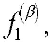


initializing a function value corresponding to β as


where 1≤m10≤n4, 1≤m11≤n4, and β1, β2, 2β and 2β-1 are all integers larger than or equal to 0 and smaller than or equal to Rvb-1. - The method of claim 4, wherein said obtaining M_index based on the second index matrix comprises:
selecting a predetermined number of indices from Mre row by row, column by column or diagonal by diagonal, as M_index. - The method of claim 18, wherein
said selecting the predetermined number of indices from Mre column by column comprises: selecting Kp indices from the p-th column of Mre, where
said selecting the predetermined number of indices from Mre row by row comprises: selecting Kq indices from the q-th row of Mre, where
said selecting the predetermined number of indices from Mre diagonal by diagonal comprises: selecting Kδ indices from the δ-th diagonal of Mre, where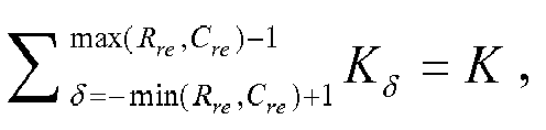
- The method of claim 18, wherein said selecting the predetermined number of indices from Mre column by column comprises at least one of:selecting Kic1 indices from the 1st, 2nd, ..., C1-th columns of Mre, where
 selecting Kic2 indices from the C2-th, (C2+1)-th, ..., C3-th columns of Mre, where
 selecting Kic3 indices from the C4-th, (C4+1)-th, ..., Cre-th columns of Mre, where
- The method of claim 18, wherein said selecting the predetermined number of indices from Mre row by row comprises at least one of:selecting Kir1 indices from the 1st, 2nd, ..., R1-th rows of Mre, where
 selecting Kir2 indices from the R2-th, (R2+1)-th, ..., R3-th rows of Mre, where
 selecting Kir3 indices from the R4-th, (R4+1)-th, ..., Rre-th rows of Mre, where
- The method of claim 18, wherein said selecting the predetermined number of indices from Mre diagonal by diagonal comprises at least one of:selecting Kid1 indices from the (-min(Rre,Cre)+1)-th, (-min(Rre,Cre)+2)-th, ..., D1-th diagonals of Mre, where
 selecting Kid2 indices from the D2-th, (D2+1)-th, ..., D3-th diagonals of Mre, where
 selecting Kid3 indices from the D4-th, (D4+1)-th, ..., (max(Rre,Cre)-1)-th diagonals of Mre, where
 where min(Rre,Cre) denotes the smaller of Rre and Cre, and max(Rre,Cre) denotes the larger of Rre and Cre.
 - The method of claim 18 or 19, wherein when the predetermined number of indices are selected based on Mre row by row, column by column or diagonal by diagonal, each index corresponding to a non-transmitted bit sequence in a second bit sequence matrix is skipped, the second bit sequence matrix being obtained from a first bit sequence matrix by using a second predetermined transform, the first bit sequence matrix being formed from the Polar encoded bit sequence, wherein the second predetermined transform comprises row permutation or column permutation.
- The method of claim 3, wherein said selecting T bits based on the second bit sequence matrix as the bit sequence to be transmitted comprises:
selecting T bits based on the second bit sequence matrix row by row, column by column or diagonal by diagonal, as the bit sequence to be transmitted. - The method of claim 24, wherein said selecting T bits based on the second bit sequence matrix row by row, column by column or diagonal by diagonal as the bit sequence to be transmitted comprises:
selecting T bits based on the second bit sequence matrix row by row, column by column or diagonal by diagonal, from a starting position t in the second bit sequence matrix, wherein when the selection reaches the first or last bit in the second bit sequence matrix, it continues with the last or first bit in the second bit sequence matrix, where 1≤t≤Rvb×Cvb. - The method of claim 24, wherein said selecting T bits from the second bit sequence matrix row by row, column by column or diagonal by diagonal as the bit sequence to be transmitted comprises:selecting the 1st to T-th bits or the (N-T+1)-th to N-th bits from the second bit sequence matrix column by column, when T is smaller than or equal to a length N of the Polar encoded bit sequence;selecting the 1st to T-th bits or the (N-T+1)-th to N-th bits from the second bit sequence matrix row by row, when T is smaller than or equal to the length N of the Polar encoded bit sequence;selecting the 1st to T-th bits or the (N-T+1)-th to N-th bits from the second bit sequence matrix diagonal by diagonal, when T is smaller than or equal to the length N of the Polar encoded bit sequence;selecting, when T is larger than the length N of the Polar encoded bit sequence, T bits row by row, column by column or diagonal by diagonal, from the t-th bit in the second bit sequence matrix, wherein when the selection reaches the first or last bit in the second bit sequence matrix, it continues with the last or first bit in the second bit sequence matrix, where 1≤t≤Rvb×Cvb and N is a non-negative integer.
- The method of claim 24, wherein said selecting T bits from the second bit sequence matrix column by column comprises at least one of:selecting Tie1 bits from the 1st, 2nd, ..., E1-th columns, where
 selecting Tie2 bits from the E2-th, (E2+1)-th, ..., E3-th columns, where
 selecting Tie3 bits from the E4-th, (E4+1)-th, ..., Evb-th columns, where
- The method of claim 24, wherein said selecting T bits from the second bit sequence matrix row by row comprises at least one of:selecting Tif1 bits from the 1st, 2nd, ..., F1-th rows, where
 selecting Tif2 bits from the F2-th, (F2+1)-th, ..., F3-th rows, where
 selecting Tif3 bits from the F4-th, (F4+1)-th, ..., Rvb-th rows, where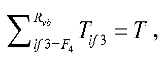
- The method of claim 24, wherein said selecting T bits from the second bit sequence matrix diagonal by diagonal comprises at least one of:selecting Tig1 bits from the (-min(Rvb,Cvb)+1)-th, (-min(Rvb,Cvb)+2)-th, ..., G1-th diagonals sequentially, where
 selecting Kig2 bits from the G2-th, (G2+1)-th, ..., G3-th diagonals, where
 selecting Kid3 bits from the G4-th, (G4+1)-th, ..., (max(Rvb,Cvb)-1)-th diagonals, where
- The method of any of claims 11-29, wherein Mog has 32 columns.
- An apparatus for sequence determination, comprising:a permuting module configured to map a first bit sequence having a length of K bits to a specified position based on M_index to obtain a second bit sequence;an encoding module configured to apply Polar encoding to the second bit sequence to obtain a Polar encoded bit sequence; anda selecting module configured to select T bits based on the Polar encoded bit sequence as a bit sequence to be transmitted,where K and T are both non-negative integers and K≤T.
- The apparatus of claim 31, further comprising:a first transform module configured to apply a first predetermined transform to a first index matrix to obtain a second index matrix and obtain M_index based on the second index matrix,wherein the first predetermined transform comprises row permutation or column permutation.
- The apparatus of claim 31 or 32, further comprising:a second transform module configured to form a first bit sequence matrix from the Polar encoded bit sequence, and apply a second predetermined transform to the first bit sequence matrix to obtain a second bit sequence matrix, wherein the second predetermined transform comprises row permutation or column permutation,wherein the selecting module is further configured to select T bits based on the second bit sequence matrix as the bit sequence to be transmitted.
- A device, comprising:
a processor configured to:map a first bit sequence having a length of K bits to a specified position based on M_index to obtain a second bit sequence;apply Polar encoding to the second bit sequence to obtain a Polar encoded bit sequence; andselect T bits based on the Polar encoded bit sequence as a bit sequence to be transmitted, where K and T are both non-negative integers and K≤T, anda memory coupled to the processor. - The device of claim 34, wherein the processor is further configured to:apply a first predetermined transform to a first index matrix to obtain a second index matrix; andobtain M_index based on the second index matrix,wherein the first predetermined transform comprises row permutation or column permutation.
- The device of claim 34 or 35, wherein the processor is further configured to:form a first bit sequence matrix from the Polar encoded bit sequence;apply a second predetermined transform to the first bit sequence matrix to obtain a second bit sequence matrix; andselect T bits based on the second bit sequence matrix as the bit sequence to be transmitted,wherein the second predetermined transform comprises row permutation or column permutation.
- A storage medium storing a program which, when executed, performs the method according to any of claims 1-30.
- A processor configured to execute a program for performing the method according to any of claims 1-30.
Priority Applications (1)
| Application Number | Priority Date | Filing Date | Title |
|---|---|---|---|
| EP24162344.6A EP4380061A3 (en) | 2017-05-05 | 2018-05-04 | Sequence determining method and apparatus, device and storage medium |
Applications Claiming Priority (3)
| Application Number | Priority Date | Filing Date | Title |
|---|---|---|---|
| CN201710314013 | 2017-05-05 | ||
| CN201710737955.9A CN108809334B (en) | 2017-05-05 | 2017-08-24 | Sequence determination method, device and equipment |
| PCT/CN2018/085645 WO2018202142A1 (en) | 2017-05-05 | 2018-05-04 | Sequence determining method and apparatus, device and storage medium |
Related Child Applications (1)
| Application Number | Title | Priority Date | Filing Date |
|---|---|---|---|
| EP24162344.6A Division EP4380061A3 (en) | 2017-05-05 | 2018-05-04 | Sequence determining method and apparatus, device and storage medium |
Publications (3)
| Publication Number | Publication Date |
|---|---|
| EP3570443A1 true EP3570443A1 (en) | 2019-11-20 |
| EP3570443A4 EP3570443A4 (en) | 2020-04-01 |
| EP3570443B1 EP3570443B1 (en) | 2024-04-10 |
Family
ID=64094987
Family Applications (2)
| Application Number | Title | Priority Date | Filing Date |
|---|---|---|---|
| EP24162344.6A Pending EP4380061A3 (en) | 2017-05-05 | 2018-05-04 | Sequence determining method and apparatus, device and storage medium |
| EP18794534.0A Active EP3570443B1 (en) | 2017-05-05 | 2018-05-04 | Polar coding with rate matching |
Family Applications Before (1)
| Application Number | Title | Priority Date | Filing Date |
|---|---|---|---|
| EP24162344.6A Pending EP4380061A3 (en) | 2017-05-05 | 2018-05-04 | Sequence determining method and apparatus, device and storage medium |
Country Status (7)
| Country | Link |
|---|---|
| US (2) | US10581461B2 (en) |
| EP (2) | EP4380061A3 (en) |
| JP (2) | JP6997214B2 (en) |
| KR (2) | KR102250284B1 (en) |
| CN (2) | CN108809334B (en) |
| AU (1) | AU2018261974B2 (en) |
| FI (1) | FI3570443T3 (en) |
Families Citing this family (3)
| Publication number | Priority date | Publication date | Assignee | Title |
|---|---|---|---|---|
| WO2019099318A1 (en) * | 2017-11-15 | 2019-05-23 | Idac Holdings, Inc. | Urllc transmissions with polar codes |
| KR102306927B1 (en) * | 2020-04-09 | 2021-09-29 | 충남대학교 산학협력단 | Area-efficient semi-parallel polar code encoder for long polar codes and implementation method thereof |
| WO2024192762A1 (en) * | 2023-03-23 | 2024-09-26 | Huawei Technologies Co., Ltd. | Methods, systems, and apparatus for bit value placement in polar coding |
Family Cites Families (28)
| Publication number | Priority date | Publication date | Assignee | Title |
|---|---|---|---|---|
| NL260659A (en) * | 1960-04-13 | |||
| US7430257B1 (en) * | 1998-02-12 | 2008-09-30 | Lot 41 Acquisition Foundation, Llc | Multicarrier sub-layer for direct sequence channel and multiple-access coding |
| DE10030407B4 (en) | 1999-07-14 | 2011-09-01 | Lg Electronics Inc. | Method for optimal rate adaptation in a mobile communication system |
| KR101435830B1 (en) | 2007-06-20 | 2014-08-29 | 엘지전자 주식회사 | How to Perform Interleaving |
| US8239710B2 (en) | 2008-10-31 | 2012-08-07 | Industrial Technology Research Institute | Communication methods and systems having permutation schemes |
| EP2536030A1 (en) | 2011-06-16 | 2012-12-19 | Panasonic Corporation | Bit permutation patterns for BICM with LDPC codes and QAM constellations |
| CN106899311B (en) * | 2012-09-24 | 2023-11-03 | 华为技术有限公司 | Mixed polar code generation method and generation device |
| KR101951663B1 (en) * | 2012-12-14 | 2019-02-25 | 삼성전자주식회사 | Method and apparatus of encoding with CRC code and polar code |
| CN103023618B (en) * | 2013-01-11 | 2015-04-22 | 北京邮电大学 | Random code length polar encoding method |
| CN104219019B (en) | 2013-05-31 | 2021-06-22 | 华为技术有限公司 | Coding method and coding device |
| JP6363721B2 (en) | 2014-02-21 | 2018-07-25 | 華為技術有限公司Huawei Technologies Co.,Ltd. | Rate matching method and apparatus for polar codes |
| CA2972655C (en) | 2014-03-24 | 2020-10-20 | Huawei Technologies Co., Ltd. | Polar code rate matching method and polar code rate matching apparatus |
| RU2669743C1 (en) * | 2014-03-31 | 2018-10-15 | Хуавэй Текнолоджиз Ко., Лтд. | Hybrid automatic request for repeating with the polar code method and device and a wireless communication device |
| CN103916220B (en) | 2014-04-15 | 2017-04-05 | 电子科技大学 | A kind of network coding cooperation communication means based on polarization code |
| KR102157667B1 (en) | 2014-05-15 | 2020-09-18 | 삼성전자주식회사 | Puncturing apparatus and puncturing method thereof |
| US10193578B2 (en) | 2014-07-10 | 2019-01-29 | The Royal Institution For The Advancement Of Learning / Mcgill University | Flexible polar encoders and decoders |
| RU2663351C1 (en) | 2014-11-27 | 2018-08-03 | Хуавэй Текнолоджиз Ко., Лтд. | Polar code rate matching method and device and wireless communication device |
| CN106171018B (en) | 2014-11-27 | 2020-01-21 | 华为技术有限公司 | Base station and signal receiving method |
| RU2685034C2 (en) | 2014-12-22 | 2019-04-16 | Хуавэй Текнолоджиз Ко., Лтд. | Encoding device and encoding method with polar code |
| CN104539393B (en) | 2015-01-07 | 2018-01-12 | 北京邮电大学 | A kind of source coding method based on polarization code |
| CN106899379B (en) | 2015-12-18 | 2020-01-17 | 华为技术有限公司 | Method and communication device for processing polar codes |
| CN105656604B (en) * | 2016-01-21 | 2019-03-26 | 北京邮电大学 | A kind of Bit Interleave Polarization Coding modulator approach and device |
| CN105811998B (en) | 2016-03-04 | 2019-01-18 | 深圳大学 | A kind of polarization code constructing method and polarization code coding/decoding system based on density evolution |
| EP3247042B1 (en) * | 2016-05-13 | 2020-09-30 | Mediatek Inc. | Bit puncturing for polar codes |
| US10567011B2 (en) * | 2016-06-17 | 2020-02-18 | Huawei Technologies Co., Ltd. | Systems and methods for piece-wise rate matching when using polar codes |
| CN106230489B (en) * | 2016-07-15 | 2019-07-16 | 西安电子科技大学 | Polarization code encoding modulation method suitable for any high order modulation |
| CN106161012B (en) * | 2016-08-26 | 2019-07-19 | 暨南大学 | A post-processing system and method for quantum key distribution based on polar code error correction |
| US10476525B2 (en) * | 2017-01-09 | 2019-11-12 | Qualcomm Incorporated | Low latency bit-reversed polar codes |
-
2017
- 2017-08-24 CN CN201710737955.9A patent/CN108809334B/en active Active
- 2017-08-24 CN CN202110785739.8A patent/CN113992303B/en active Active
-
2018
- 2018-05-04 JP JP2019560749A patent/JP6997214B2/en active Active
- 2018-05-04 KR KR1020197035957A patent/KR102250284B1/en active Active
- 2018-05-04 EP EP24162344.6A patent/EP4380061A3/en active Pending
- 2018-05-04 EP EP18794534.0A patent/EP3570443B1/en active Active
- 2018-05-04 KR KR1020217013466A patent/KR102382491B1/en active Active
- 2018-05-04 FI FIEP18794534.0T patent/FI3570443T3/en active
- 2018-05-04 AU AU2018261974A patent/AU2018261974B2/en active Active
-
2019
- 2019-06-19 US US16/446,605 patent/US10581461B2/en active Active
-
2020
- 2020-03-02 US US16/807,114 patent/US11271592B2/en active Active
-
2021
- 2021-12-16 JP JP2021203826A patent/JP7332673B2/en active Active
Also Published As
| Publication number | Publication date |
|---|---|
| JP6997214B2 (en) | 2022-01-17 |
| EP3570443B1 (en) | 2024-04-10 |
| EP4380061A3 (en) | 2024-07-10 |
| US20190326929A1 (en) | 2019-10-24 |
| KR20200003185A (en) | 2020-01-08 |
| CN113992303A (en) | 2022-01-28 |
| KR20210054596A (en) | 2021-05-13 |
| CN113992303B (en) | 2023-06-02 |
| JP7332673B2 (en) | 2023-08-23 |
| US20200204194A1 (en) | 2020-06-25 |
| JP2022037127A (en) | 2022-03-08 |
| CN108809334A (en) | 2018-11-13 |
| EP3570443A4 (en) | 2020-04-01 |
| AU2018261974B2 (en) | 2021-07-08 |
| EP4380061A2 (en) | 2024-06-05 |
| AU2018261974A1 (en) | 2019-12-12 |
| JP2020520596A (en) | 2020-07-09 |
| FI3570443T3 (en) | 2024-06-17 |
| US10581461B2 (en) | 2020-03-03 |
| KR102382491B1 (en) | 2022-04-01 |
| US11271592B2 (en) | 2022-03-08 |
| KR102250284B1 (en) | 2021-05-12 |
| CN108809334B (en) | 2021-07-20 |
Similar Documents
| Publication | Publication Date | Title |
|---|---|---|
| US20080077843A1 (en) | Apparatus and Method for Decoding Using Channel Code | |
| US11271592B2 (en) | Method and apparatus for sequence determination, device and storage medium | |
| CN103325425B (en) | Memory controller | |
| US10382069B2 (en) | Data encoding by efficient inversion of a parity-check sub-matrix | |
| JP2004147318A (en) | LDPC decoding apparatus and method | |
| CN109889205B (en) | Encoding method and system, decoding method and system, encoding and decoding method and system | |
| US20100269011A1 (en) | Apparatus and method for decoding low density parity check code using prototype matrix | |
| US10033407B2 (en) | Optimization of low density parity-check code encoder based on a search for an independent set of nodes | |
| US8438448B2 (en) | Decoding method and device for low density generator matrix codes | |
| KR20150131541A (en) | encoding apparatus and encoding method thereof | |
| US20100185913A1 (en) | Method for decoding ldpc code and the circuit thereof | |
| CN112583420B (en) | A data processing method and decoder | |
| KR20210057787A (en) | Turbo product code decoding method, apparatus, decoder and computer recording medium | |
| KR20180034178A (en) | Method of transmitting data, method of storing data, and method of encoding data using progressive polar channel coding in flash memory and communications | |
| CN104485970B (en) | The building method of solid size rate, the pattern matrix of multi code Rate of Chinese character QC LDPC codes | |
| US8892985B2 (en) | Decoding and optimized implementation of SECDED codes over GF(q) | |
| CN114362764B (en) | Method and device for constructing channel coding check matrix in URLLC scenario | |
| CN101305521B (en) | Method of encoding and decoding using low density parity check code | |
| US20210203364A1 (en) | Apparatuses and methods for mapping frozen sets between polar codes and product codes | |
| WO2018202142A1 (en) | Sequence determining method and apparatus, device and storage medium | |
| CN112838871B (en) | LDPC code encoding method, encoder and satellite navigation system for satellite navigation | |
| CN112838872B (en) | LDPC code decoding method, decoder and receiver for satellite navigation | |
| CN105474548B (en) | A channel coding method and device | |
| KR20040080734A (en) | Method of demodulating for efficient error-correction and apparatus thereof |
Legal Events
| Date | Code | Title | Description |
|---|---|---|---|
| STAA | Information on the status of an ep patent application or granted ep patent |
Free format text: STATUS: THE INTERNATIONAL PUBLICATION HAS BEEN MADE |
|
| PUAI | Public reference made under article 153(3) epc to a published international application that has entered the european phase |
Free format text: ORIGINAL CODE: 0009012 |
|
| STAA | Information on the status of an ep patent application or granted ep patent |
Free format text: STATUS: REQUEST FOR EXAMINATION WAS MADE |
|
| 17P | Request for examination filed |
Effective date: 20190816 |
|
| AK | Designated contracting states |
Kind code of ref document: A1 Designated state(s): AL AT BE BG CH CY CZ DE DK EE ES FI FR GB GR HR HU IE IS IT LI LT LU LV MC MK MT NL NO PL PT RO RS SE SI SK SM TR |
|
| AX | Request for extension of the european patent |
Extension state: BA ME |
|
| A4 | Supplementary search report drawn up and despatched |
Effective date: 20200227 |
|
| RIC1 | Information provided on ipc code assigned before grant |
Ipc: H03M 13/13 20060101AFI20200222BHEP Ipc: H03M 13/00 20060101ALI20200222BHEP Ipc: H03M 13/27 20060101ALI20200222BHEP |
|
| DAV | Request for validation of the european patent (deleted) | ||
| DAX | Request for extension of the european patent (deleted) | ||
| STAA | Information on the status of an ep patent application or granted ep patent |
Free format text: STATUS: EXAMINATION IS IN PROGRESS |
|
| 17Q | First examination report despatched |
Effective date: 20220131 |
|
| GRAP | Despatch of communication of intention to grant a patent |
Free format text: ORIGINAL CODE: EPIDOSNIGR1 |
|
| STAA | Information on the status of an ep patent application or granted ep patent |
Free format text: STATUS: GRANT OF PATENT IS INTENDED |
|
| INTG | Intention to grant announced |
Effective date: 20230515 |
|
| GRAJ | Information related to disapproval of communication of intention to grant by the applicant or resumption of examination proceedings by the epo deleted |
Free format text: ORIGINAL CODE: EPIDOSDIGR1 |
|
| STAA | Information on the status of an ep patent application or granted ep patent |
Free format text: STATUS: EXAMINATION IS IN PROGRESS |
|
| GRAS | Grant fee paid |
Free format text: ORIGINAL CODE: EPIDOSNIGR3 |
|
| STAA | Information on the status of an ep patent application or granted ep patent |
Free format text: STATUS: GRANT OF PATENT IS INTENDED |
|
| GRAP | Despatch of communication of intention to grant a patent |
Free format text: ORIGINAL CODE: EPIDOSNIGR1 |
|
| INTC | Intention to grant announced (deleted) | ||
| INTG | Intention to grant announced |
Effective date: 20231019 |
|
| GRAA | (expected) grant |
Free format text: ORIGINAL CODE: 0009210 |
|
| STAA | Information on the status of an ep patent application or granted ep patent |
Free format text: STATUS: THE PATENT HAS BEEN GRANTED |
|
| AK | Designated contracting states |
Kind code of ref document: B1 Designated state(s): AL AT BE BG CH CY CZ DE DK EE ES FI FR GB GR HR HU IE IS IT LI LT LU LV MC MK MT NL NO PL PT RO RS SE SI SK SM TR |
|
| REG | Reference to a national code |
Ref country code: GB Ref legal event code: FG4D |
|
| REG | Reference to a national code |
Ref country code: CH Ref legal event code: EP |
|
| REG | Reference to a national code |
Ref country code: DE Ref legal event code: R096 Ref document number: 602018067903 Country of ref document: DE |
|
| REG | Reference to a national code |
Ref country code: IE Ref legal event code: FG4D |
|
| REG | Reference to a national code |
Ref country code: FI Ref legal event code: FGE |
|
| REG | Reference to a national code |
Ref country code: SE Ref legal event code: TRGR |
|
| REG | Reference to a national code |
Ref country code: NL Ref legal event code: FP |
|
| REG | Reference to a national code |
Ref country code: LT Ref legal event code: MG9D |
|
| REG | Reference to a national code |
Ref country code: AT Ref legal event code: MK05 Ref document number: 1675966 Country of ref document: AT Kind code of ref document: T Effective date: 20240410 |
|
| PG25 | Lapsed in a contracting state [announced via postgrant information from national office to epo] |
Ref country code: IS Free format text: LAPSE BECAUSE OF FAILURE TO SUBMIT A TRANSLATION OF THE DESCRIPTION OR TO PAY THE FEE WITHIN THE PRESCRIBED TIME-LIMIT Effective date: 20240810 |
|
| PG25 | Lapsed in a contracting state [announced via postgrant information from national office to epo] |
Ref country code: BG Free format text: LAPSE BECAUSE OF FAILURE TO SUBMIT A TRANSLATION OF THE DESCRIPTION OR TO PAY THE FEE WITHIN THE PRESCRIBED TIME-LIMIT Effective date: 20240410 |
|
| PG25 | Lapsed in a contracting state [announced via postgrant information from national office to epo] |
Ref country code: HR Free format text: LAPSE BECAUSE OF FAILURE TO SUBMIT A TRANSLATION OF THE DESCRIPTION OR TO PAY THE FEE WITHIN THE PRESCRIBED TIME-LIMIT Effective date: 20240410 |
|
| PG25 | Lapsed in a contracting state [announced via postgrant information from national office to epo] |
Ref country code: GR Free format text: LAPSE BECAUSE OF FAILURE TO SUBMIT A TRANSLATION OF THE DESCRIPTION OR TO PAY THE FEE WITHIN THE PRESCRIBED TIME-LIMIT Effective date: 20240711 |
|
| PG25 | Lapsed in a contracting state [announced via postgrant information from national office to epo] |
Ref country code: PT Free format text: LAPSE BECAUSE OF FAILURE TO SUBMIT A TRANSLATION OF THE DESCRIPTION OR TO PAY THE FEE WITHIN THE PRESCRIBED TIME-LIMIT Effective date: 20240812 |
|
| PG25 | Lapsed in a contracting state [announced via postgrant information from national office to epo] |
Ref country code: ES Free format text: LAPSE BECAUSE OF FAILURE TO SUBMIT A TRANSLATION OF THE DESCRIPTION OR TO PAY THE FEE WITHIN THE PRESCRIBED TIME-LIMIT Effective date: 20240410 |
|
| PG25 | Lapsed in a contracting state [announced via postgrant information from national office to epo] |
Ref country code: AT Free format text: LAPSE BECAUSE OF FAILURE TO SUBMIT A TRANSLATION OF THE DESCRIPTION OR TO PAY THE FEE WITHIN THE PRESCRIBED TIME-LIMIT Effective date: 20240410 |
|
| PG25 | Lapsed in a contracting state [announced via postgrant information from national office to epo] |
Ref country code: PL Free format text: LAPSE BECAUSE OF FAILURE TO SUBMIT A TRANSLATION OF THE DESCRIPTION OR TO PAY THE FEE WITHIN THE PRESCRIBED TIME-LIMIT Effective date: 20240410 |
|
| PG25 | Lapsed in a contracting state [announced via postgrant information from national office to epo] |
Ref country code: LV Free format text: LAPSE BECAUSE OF FAILURE TO SUBMIT A TRANSLATION OF THE DESCRIPTION OR TO PAY THE FEE WITHIN THE PRESCRIBED TIME-LIMIT Effective date: 20240410 |
|
| PG25 | Lapsed in a contracting state [announced via postgrant information from national office to epo] |
Ref country code: PT Free format text: LAPSE BECAUSE OF FAILURE TO SUBMIT A TRANSLATION OF THE DESCRIPTION OR TO PAY THE FEE WITHIN THE PRESCRIBED TIME-LIMIT Effective date: 20240812 Ref country code: PL Free format text: LAPSE BECAUSE OF FAILURE TO SUBMIT A TRANSLATION OF THE DESCRIPTION OR TO PAY THE FEE WITHIN THE PRESCRIBED TIME-LIMIT Effective date: 20240410 Ref country code: NO Free format text: LAPSE BECAUSE OF FAILURE TO SUBMIT A TRANSLATION OF THE DESCRIPTION OR TO PAY THE FEE WITHIN THE PRESCRIBED TIME-LIMIT Effective date: 20240710 Ref country code: LV Free format text: LAPSE BECAUSE OF FAILURE TO SUBMIT A TRANSLATION OF THE DESCRIPTION OR TO PAY THE FEE WITHIN THE PRESCRIBED TIME-LIMIT Effective date: 20240410 Ref country code: IS Free format text: LAPSE BECAUSE OF FAILURE TO SUBMIT A TRANSLATION OF THE DESCRIPTION OR TO PAY THE FEE WITHIN THE PRESCRIBED TIME-LIMIT Effective date: 20240810 Ref country code: HR Free format text: LAPSE BECAUSE OF FAILURE TO SUBMIT A TRANSLATION OF THE DESCRIPTION OR TO PAY THE FEE WITHIN THE PRESCRIBED TIME-LIMIT Effective date: 20240410 Ref country code: GR Free format text: LAPSE BECAUSE OF FAILURE TO SUBMIT A TRANSLATION OF THE DESCRIPTION OR TO PAY THE FEE WITHIN THE PRESCRIBED TIME-LIMIT Effective date: 20240711 Ref country code: ES Free format text: LAPSE BECAUSE OF FAILURE TO SUBMIT A TRANSLATION OF THE DESCRIPTION OR TO PAY THE FEE WITHIN THE PRESCRIBED TIME-LIMIT Effective date: 20240410 Ref country code: BG Free format text: LAPSE BECAUSE OF FAILURE TO SUBMIT A TRANSLATION OF THE DESCRIPTION OR TO PAY THE FEE WITHIN THE PRESCRIBED TIME-LIMIT Effective date: 20240410 Ref country code: AT Free format text: LAPSE BECAUSE OF FAILURE TO SUBMIT A TRANSLATION OF THE DESCRIPTION OR TO PAY THE FEE WITHIN THE PRESCRIBED TIME-LIMIT Effective date: 20240410 Ref country code: RS Free format text: LAPSE BECAUSE OF FAILURE TO SUBMIT A TRANSLATION OF THE DESCRIPTION OR TO PAY THE FEE WITHIN THE PRESCRIBED TIME-LIMIT Effective date: 20240710 |
|
| REG | Reference to a national code |
Ref country code: CH Ref legal event code: PL |
|
| REG | Reference to a national code |
Ref country code: DE Ref legal event code: R097 Ref document number: 602018067903 Country of ref document: DE |
|
| PG25 | Lapsed in a contracting state [announced via postgrant information from national office to epo] |
Ref country code: DK Free format text: LAPSE BECAUSE OF FAILURE TO SUBMIT A TRANSLATION OF THE DESCRIPTION OR TO PAY THE FEE WITHIN THE PRESCRIBED TIME-LIMIT Effective date: 20240410 |
|
| PG25 | Lapsed in a contracting state [announced via postgrant information from national office to epo] |
Ref country code: LU Free format text: LAPSE BECAUSE OF NON-PAYMENT OF DUE FEES Effective date: 20240504 |
|
| PG25 | Lapsed in a contracting state [announced via postgrant information from national office to epo] |
Ref country code: EE Free format text: LAPSE BECAUSE OF FAILURE TO SUBMIT A TRANSLATION OF THE DESCRIPTION OR TO PAY THE FEE WITHIN THE PRESCRIBED TIME-LIMIT Effective date: 20240410 |
|
| PG25 | Lapsed in a contracting state [announced via postgrant information from national office to epo] |
Ref country code: RO Free format text: LAPSE BECAUSE OF FAILURE TO SUBMIT A TRANSLATION OF THE DESCRIPTION OR TO PAY THE FEE WITHIN THE PRESCRIBED TIME-LIMIT Effective date: 20240410 Ref country code: SK Free format text: LAPSE BECAUSE OF FAILURE TO SUBMIT A TRANSLATION OF THE DESCRIPTION OR TO PAY THE FEE WITHIN THE PRESCRIBED TIME-LIMIT Effective date: 20240410 |
|
| PG25 | Lapsed in a contracting state [announced via postgrant information from national office to epo] |
Ref country code: SM Free format text: LAPSE BECAUSE OF FAILURE TO SUBMIT A TRANSLATION OF THE DESCRIPTION OR TO PAY THE FEE WITHIN THE PRESCRIBED TIME-LIMIT Effective date: 20240410 |
|
| PG25 | Lapsed in a contracting state [announced via postgrant information from national office to epo] |
Ref country code: SM Free format text: LAPSE BECAUSE OF FAILURE TO SUBMIT A TRANSLATION OF THE DESCRIPTION OR TO PAY THE FEE WITHIN THE PRESCRIBED TIME-LIMIT Effective date: 20240410 Ref country code: SK Free format text: LAPSE BECAUSE OF FAILURE TO SUBMIT A TRANSLATION OF THE DESCRIPTION OR TO PAY THE FEE WITHIN THE PRESCRIBED TIME-LIMIT Effective date: 20240410 Ref country code: RO Free format text: LAPSE BECAUSE OF FAILURE TO SUBMIT A TRANSLATION OF THE DESCRIPTION OR TO PAY THE FEE WITHIN THE PRESCRIBED TIME-LIMIT Effective date: 20240410 Ref country code: LU Free format text: LAPSE BECAUSE OF NON-PAYMENT OF DUE FEES Effective date: 20240504 Ref country code: EE Free format text: LAPSE BECAUSE OF FAILURE TO SUBMIT A TRANSLATION OF THE DESCRIPTION OR TO PAY THE FEE WITHIN THE PRESCRIBED TIME-LIMIT Effective date: 20240410 Ref country code: DK Free format text: LAPSE BECAUSE OF FAILURE TO SUBMIT A TRANSLATION OF THE DESCRIPTION OR TO PAY THE FEE WITHIN THE PRESCRIBED TIME-LIMIT Effective date: 20240410 Ref country code: CH Free format text: LAPSE BECAUSE OF NON-PAYMENT OF DUE FEES Effective date: 20240531 Ref country code: MC Free format text: LAPSE BECAUSE OF FAILURE TO SUBMIT A TRANSLATION OF THE DESCRIPTION OR TO PAY THE FEE WITHIN THE PRESCRIBED TIME-LIMIT Effective date: 20240410 |
|
| PG25 | Lapsed in a contracting state [announced via postgrant information from national office to epo] |
Ref country code: IT Free format text: LAPSE BECAUSE OF FAILURE TO SUBMIT A TRANSLATION OF THE DESCRIPTION OR TO PAY THE FEE WITHIN THE PRESCRIBED TIME-LIMIT Effective date: 20240410 |
|
| PLBE | No opposition filed within time limit |
Free format text: ORIGINAL CODE: 0009261 |
|
| STAA | Information on the status of an ep patent application or granted ep patent |
Free format text: STATUS: NO OPPOSITION FILED WITHIN TIME LIMIT |
|
| REG | Reference to a national code |
Ref country code: BE Ref legal event code: MM Effective date: 20240531 |
|
| 26N | No opposition filed |
Effective date: 20250113 |
|
| PG25 | Lapsed in a contracting state [announced via postgrant information from national office to epo] |
Ref country code: IE Free format text: LAPSE BECAUSE OF NON-PAYMENT OF DUE FEES Effective date: 20240504 |
|
| P01 | Opt-out of the competence of the unified patent court (upc) registered |
Free format text: CASE NUMBER: APP_12700/2025 Effective date: 20250314 |
|
| PG25 | Lapsed in a contracting state [announced via postgrant information from national office to epo] |
Ref country code: SI Free format text: LAPSE BECAUSE OF FAILURE TO SUBMIT A TRANSLATION OF THE DESCRIPTION OR TO PAY THE FEE WITHIN THE PRESCRIBED TIME-LIMIT Effective date: 20240410 Ref country code: BE Free format text: LAPSE BECAUSE OF NON-PAYMENT OF DUE FEES Effective date: 20240531 |
|
| PGFP | Annual fee paid to national office [announced via postgrant information from national office to epo] |
Ref country code: FI Payment date: 20250513 Year of fee payment: 8 |
|
| PGFP | Annual fee paid to national office [announced via postgrant information from national office to epo] |
Ref country code: DE Payment date: 20250311 Year of fee payment: 8 |
|
| PGFP | Annual fee paid to national office [announced via postgrant information from national office to epo] |
Ref country code: CZ Payment date: 20250423 Year of fee payment: 8 |
|
| PG25 | Lapsed in a contracting state [announced via postgrant information from national office to epo] |
Ref country code: CY Free format text: LAPSE BECAUSE OF FAILURE TO SUBMIT A TRANSLATION OF THE DESCRIPTION OR TO PAY THE FEE WITHIN THE PRESCRIBED TIME-LIMIT; INVALID AB INITIO Effective date: 20180504 |
|
| PG25 | Lapsed in a contracting state [announced via postgrant information from national office to epo] |
Ref country code: HU Free format text: LAPSE BECAUSE OF FAILURE TO SUBMIT A TRANSLATION OF THE DESCRIPTION OR TO PAY THE FEE WITHIN THE PRESCRIBED TIME-LIMIT; INVALID AB INITIO Effective date: 20180504 |
|
| PGFP | Annual fee paid to national office [announced via postgrant information from national office to epo] |
Ref country code: SE Payment date: 20260312 Year of fee payment: 9 |
|
| PGFP | Annual fee paid to national office [announced via postgrant information from national office to epo] |
Ref country code: GB Payment date: 20260312 Year of fee payment: 9 |
|
| PGFP | Annual fee paid to national office [announced via postgrant information from national office to epo] |
Ref country code: NL Payment date: 20260317 Year of fee payment: 9 |
|
| PGFP | Annual fee paid to national office [announced via postgrant information from national office to epo] |
Ref country code: FR Payment date: 20260309 Year of fee payment: 9 |