EP3570402A1 - Uniform generator control unit including multiple permanent magnet generator inputs - Google Patents
Uniform generator control unit including multiple permanent magnet generator inputs Download PDFInfo
- Publication number
- EP3570402A1 EP3570402A1 EP19174682.5A EP19174682A EP3570402A1 EP 3570402 A1 EP3570402 A1 EP 3570402A1 EP 19174682 A EP19174682 A EP 19174682A EP 3570402 A1 EP3570402 A1 EP 3570402A1
- Authority
- EP
- European Patent Office
- Prior art keywords
- winding
- configuration
- input
- control unit
- generator control
- Prior art date
- Legal status (The legal status is an assumption and is not a legal conclusion. Google has not performed a legal analysis and makes no representation as to the accuracy of the status listed.)
- Granted
Links
Images


Classifications
-
- H—ELECTRICITY
- H02—GENERATION; CONVERSION OR DISTRIBUTION OF ELECTRIC POWER
- H02P—CONTROL OR REGULATION OF ELECTRIC MOTORS, ELECTRIC GENERATORS OR DYNAMO-ELECTRIC CONVERTERS; CONTROLLING TRANSFORMERS, REACTORS OR CHOKE COILS
- H02P9/00—Arrangements for controlling electric generators for the purpose of obtaining a desired output
-
- B—PERFORMING OPERATIONS; TRANSPORTING
- B64—AIRCRAFT; AVIATION; COSMONAUTICS
- B64D—EQUIPMENT FOR FITTING IN OR TO AIRCRAFT; FLIGHT SUITS; PARACHUTES; ARRANGEMENT OR MOUNTING OF POWER PLANTS OR PROPULSION TRANSMISSIONS IN AIRCRAFT
- B64D41/00—Power installations for auxiliary purposes
-
- H—ELECTRICITY
- H01—ELECTRIC ELEMENTS
- H01F—MAGNETS; INDUCTANCES; TRANSFORMERS; SELECTION OF MATERIALS FOR THEIR MAGNETIC PROPERTIES
- H01F29/00—Variable transformers or inductances not covered by group H01F21/00
- H01F29/02—Variable transformers or inductances not covered by group H01F21/00 with tappings on coil or winding; with provision for rearrangement or interconnection of windings
-
- H—ELECTRICITY
- H02—GENERATION; CONVERSION OR DISTRIBUTION OF ELECTRIC POWER
- H02M—APPARATUS FOR CONVERSION BETWEEN AC AND AC, BETWEEN AC AND DC, OR BETWEEN DC AND DC, AND FOR USE WITH MAINS OR SIMILAR POWER SUPPLY SYSTEMS; CONVERSION OF DC OR AC INPUT POWER INTO SURGE OUTPUT POWER; CONTROL OR REGULATION THEREOF
- H02M5/00—Conversion of AC power input into AC power output, e.g. for change of voltage, for change of frequency, for change of number of phases
- H02M5/02—Conversion of AC power input into AC power output, e.g. for change of voltage, for change of frequency, for change of number of phases without intermediate conversion into DC
- H02M5/04—Conversion of AC power input into AC power output, e.g. for change of voltage, for change of frequency, for change of number of phases without intermediate conversion into DC by static converters
- H02M5/10—Conversion of AC power input into AC power output, e.g. for change of voltage, for change of frequency, for change of number of phases without intermediate conversion into DC by static converters using transformers
- H02M5/12—Conversion of AC power input into AC power output, e.g. for change of voltage, for change of frequency, for change of number of phases without intermediate conversion into DC by static converters using transformers for conversion of voltage or current amplitude only
-
- B—PERFORMING OPERATIONS; TRANSPORTING
- B64—AIRCRAFT; AVIATION; COSMONAUTICS
- B64D—EQUIPMENT FOR FITTING IN OR TO AIRCRAFT; FLIGHT SUITS; PARACHUTES; ARRANGEMENT OR MOUNTING OF POWER PLANTS OR PROPULSION TRANSMISSIONS IN AIRCRAFT
- B64D2221/00—Electric power distribution systems onboard aircraft
-
- B—PERFORMING OPERATIONS; TRANSPORTING
- B64—AIRCRAFT; AVIATION; COSMONAUTICS
- B64D—EQUIPMENT FOR FITTING IN OR TO AIRCRAFT; FLIGHT SUITS; PARACHUTES; ARRANGEMENT OR MOUNTING OF POWER PLANTS OR PROPULSION TRANSMISSIONS IN AIRCRAFT
- B64D33/00—Arrangement in aircraft of power plant parts or auxiliaries not otherwise provided for
-
- H—ELECTRICITY
- H02—GENERATION; CONVERSION OR DISTRIBUTION OF ELECTRIC POWER
- H02J—ELECTRIC POWER NETWORKS; CIRCUIT ARRANGEMENTS OR SYSTEMS FOR SUPPLYING OR DISTRIBUTING ELECTRIC POWER; SYSTEMS FOR STORING ELECTRIC ENERGY
- H02J2105/00—Networks for supplying or distributing electric power characterised by their spatial reach or by the load
- H02J2105/30—Networks for supplying or distributing electric power characterised by their spatial reach or by the load the load networks being external to vehicles, i.e. exchanging power with vehicles
- H02J2105/32—Networks for supplying or distributing electric power characterised by their spatial reach or by the load the load networks being external to vehicles, i.e. exchanging power with vehicles for aircrafts
-
- H—ELECTRICITY
- H02—GENERATION; CONVERSION OR DISTRIBUTION OF ELECTRIC POWER
- H02M—APPARATUS FOR CONVERSION BETWEEN AC AND AC, BETWEEN AC AND DC, OR BETWEEN DC AND DC, AND FOR USE WITH MAINS OR SIMILAR POWER SUPPLY SYSTEMS; CONVERSION OF DC OR AC INPUT POWER INTO SURGE OUTPUT POWER; CONTROL OR REGULATION THEREOF
- H02M1/00—Details of apparatus for conversion
- H02M1/0067—Converter structures employing plural converter units, other than for parallel operation of the units on a single load
- H02M1/0074—Plural converter units whose inputs are connected in series
-
- H—ELECTRICITY
- H02—GENERATION; CONVERSION OR DISTRIBUTION OF ELECTRIC POWER
- H02M—APPARATUS FOR CONVERSION BETWEEN AC AND AC, BETWEEN AC AND DC, OR BETWEEN DC AND DC, AND FOR USE WITH MAINS OR SIMILAR POWER SUPPLY SYSTEMS; CONVERSION OF DC OR AC INPUT POWER INTO SURGE OUTPUT POWER; CONTROL OR REGULATION THEREOF
- H02M5/00—Conversion of AC power input into AC power output, e.g. for change of voltage, for change of frequency, for change of number of phases
- H02M5/02—Conversion of AC power input into AC power output, e.g. for change of voltage, for change of frequency, for change of number of phases without intermediate conversion into DC
- H02M5/04—Conversion of AC power input into AC power output, e.g. for change of voltage, for change of frequency, for change of number of phases without intermediate conversion into DC by static converters
- H02M5/10—Conversion of AC power input into AC power output, e.g. for change of voltage, for change of frequency, for change of number of phases without intermediate conversion into DC by static converters using transformers
- H02M5/14—Conversion of AC power input into AC power output, e.g. for change of voltage, for change of frequency, for change of number of phases without intermediate conversion into DC by static converters using transformers for conversion between circuits of different phase number
-
- H—ELECTRICITY
- H02—GENERATION; CONVERSION OR DISTRIBUTION OF ELECTRIC POWER
- H02P—CONTROL OR REGULATION OF ELECTRIC MOTORS, ELECTRIC GENERATORS OR DYNAMO-ELECTRIC CONVERTERS; CONTROLLING TRANSFORMERS, REACTORS OR CHOKE COILS
- H02P2101/00—Special adaptation of control arrangements for generators
- H02P2101/30—Special adaptation of control arrangements for generators for aircraft
Definitions
- the present disclosure relates generally to aircraft generator control units, and more specifically to aircraft generator control units including multiple permanent magnet generator inputs and a single power output.
- Each of the generators includes an internal permanent magnet generator that provides internal operational power to the generator control unit and to the generator.
- the different permanent magnet generators used throughout the aircraft can include varied voltage and current outputs, and can require distinct generator control unit (GCU) internal transformer configurations to provide the correct control power to the corresponding generator.
- GCU generator control unit
- Existing aircraft usually achieve this normalization by either including a distinct generator control unit for each generator, or including a dedicated transformer for each permanent magnet generator within every generator control unit.
- the inclusion of multiple distinct generator control units increases system complexity and the inclusion of multiple distinct transformers within each generator control unit increases the weight carried by the aircraft.
- a generator control unit includes a plurality of permanent magnet generator (PMG) inputs, a transformer including a multi-configuration input winding and at least one output winding, each PMG input in the plurality of PMG inputs being connected to the multi-configuration input winding at a corresponding input winding input.
- PMG permanent magnet generator
- the multi-configuration input winding is a multi-tapped primary winding having a plurality of phase legs.
- the multi-configuration input winding is a multiple isolated series winding.
- the multi-configuration input winding includes a plurality of parallel primary windings, each of the parallel primary windings having a distinct parallel primary winding configuration.
- the distinct parallel primary winding configuration includes a distinct number of winding turns from each other parallel primary winding.
- each of the parallel winding configurations corresponds to at least one PMG input in the plurality of PMG inputs.
- the at least one output winding includes a single output winding.
- the at least one output winding includes a plurality of output windings.
- the multi-configuration input winding includes a plurality of phase legs, with each phase leg comprising an identical number of isolated (floating) windings.
- an aircraft electrical system includes a plurality of generators, each of the generators including a corresponding permanent magnet generator (PMG) and a corresponding uniform generator control unit, and being connected to a power distribution system, and each uniform generator control unit being identical to each other uniform generator control unit and including a transformer having a multi-configuration input winding and at least one output winding, wherein each PMG is connected to a single configuration of the corresponding multi-configuration input winding.
- PMG permanent magnet generator
- the multi-configuration input winding is a single winding having a plurality of phase legs, with each phase leg including a plurality of input taps.
- the multi-configuration input winding is a multiple isolated series winding.
- At least two of the PMGs are connected to a corresponding first input tap in the plurality of input taps of the corresponding generator control unit in a first configuration, and wherein at least one other of the PMGs in the plurality of PMGs is connected to the corresponding first input tap in the corresponding generator control unit in a second configuration.
- the multi-configuration input winding is a plurality of parallel input windings, and wherein each input winding in the plurality of parallel input windings has a distinct number of turns per leg.
- At least one of the parallel input windings in the plurality of parallel input windings is a multi-tapped input winding.
- each uniform generator control unit includes a number of inputs, and the number of inputs is less than the number of permanent magnet generators including the uniform generator control units.
- An exemplary method for standardizing aircraft components includes providing a uniform generator control unit to each generator on an aircraft, the uniform generator control unit including a plurality of permanent magnet generator (PMG) inputs, a transformer including a multi-configuration input winding and at least one output winding, and each PMG input in the plurality of PMG inputs being connected to the multi-configuration input winding at a corresponding input winding input, and passing power from a PMG through a corresponding configuration of the multi-configuration transformer, thereby generating operational power for the corresponding generator control unit and the corresponding generator.
- PMG permanent magnet generator
- passing power through the corresponding configuration of the multi-configuration transformer comprises passing power from the PMG corresponding through a distinct parallel input winding of the multi-configuration transformer.
- passing power through the corresponding configuration of the multi-configuration transformer comprises passing power from the permanent magnet generator in the plurality of PMGs to a distinct input tap at each phase leg of the single transformer.
- FIG 1 schematically illustrates an aircraft 10 including a power distribution system 20 for distributing electrical power to multiple onboard electrical systems 30.
- the electrical power is generated by multiple onboard generators 40, each of which includes an internal permanent magnet generator. While illustrated herein as including three generators 40, one of skill in the art will appreciate that the system described herein can be expanded to include any number of additional generators 40 without requiring substantial alterations to the disclosed system.
- Each of the generators 40 receives rotational power from corresponding aircraft components, and has a unique internal permanent magnet generator construction dictated by its location within the aircraft 10 and the component driving the rotation of the generator 40. Output power generated by each generator 40 is provided to the power distribution system 20.
- each of the generators 40 includes a generator control unit 50.
- the generator control unit 50 draws internal control power from the corresponding permanent magnet generator, and regulates the output power provided by the generator 40 in order to ensure that the output power is within the range of power that can be distributed via the power distribution system 20.
- the generator control unit 50 can further include a computerized component assisting the operation and control of the generator 40 including the generator control unit 50 according to any known generator control configuration.
- each permanent magnet generator has a distinct part number and a distinct generator control unit configuration due to the distinct power output capabilities of a given generator on the aircraft.
- the generator control units 50 it is common for the generator control units 50 to have a single part number, and utilize a single standardized configuration across all of the generators 40.
- utilizing a single internal transformer within the corresponding generator control units 50 for providing the internal power to the permanent magnet generator is an operable solution.
- the output voltage capabilities of the permanent magnet generators can be too far varied resulting in an aircraft 10 where a generator control unit 50 having a single internal transformer configuration cannot be utilized for all permanent magnet generators included within the generators 40.
- FIG. 2 schematically illustrates an exemplary generator control unit 50 that can be universally used in all of the generators 40, despite the extreme variation in power capabilities, according to one embodiment.
- the generator control unit 50 has multiple three phase inputs 110, 112, 114, with each input 110, 112, 114 corresponding to one or more permanent magnet generators on the aircraft 10.
- a single input 110, 112, 114 corresponding to that specific power configuration can be provided.
- the permanent magnet generators within the generators 40 on each of the aircraft engines have the same power requirements, only a single generator control unit 50 input is required to cover that configuration.
- the exemplary transformer 120 includes a multi-configuration primary winding 122 paired with a single secondary winding 124. In alternative examples, multiple secondary windings 124 can be utilized according to any known transformer configuration. These windings 122, 124 can alternately be referred to as an input winding 122 and an output winding 124.
- the transformer 120 receives power from the corresponding permanent magnet generator at one of the inputs 110, 112, 114 and converts the received power into internal operating power based on the ratio of the turns in the primary winding 122 at the input 110, 112, 114, where the power is received, to the number of turns in the secondary winding(s) 124.
- the internal operating power for the generator control unit 50 is drawn from the corresponding permanent magnet generator, and allows for the regulation and control of the output power generated by the generator 40.
- the generator output power is then provided to the power distribution system 20.
- the multiple configuration primary winding 122 includes multiple connections, each of which is configured to pass connected power through a corresponding number of turns.
- the number of turns at each input 110, 112, 114 is configured such that, when connected correctly, the connected permanent magnet generator causes the secondary winding(s) 124 to output power at a predefined internal operating voltage.
- each input 110, 112, 114 is connected to a corresponding configuration of each phase leg of the primary winding 122.
- the multi configuration nature of the primary winding 122 allows a single primary winding 122 structure to receive input power at different voltage and current levels, and transform the power to a corresponding desired internal operating power through the single secondary winding 124.
- identical generator control units 50 can be used throughout all of the generators 40 by connecting each generator control unit 50 to its corresponding permanent magnet generator via the correct inputs 110, 112, 114.
- the multi configurations are achieved via the use of multiple parallel primary windings, each paired with the secondary winding(s) 124 and each having a distinct number of winding turns.
- a single primary winding 122 with multiple taps can be utilized, as in the example of Figure 4 .
- each tap corresponds to a distinct number of turns on a given phase leg.
- Figure 3 schematically illustrates an exemplary generator control unit 50 including a transformer 220 having three parallel primary windings 222, 222', 222" and a single secondary winding 224.
- Each of the parallel primary windings 222, 222', 222" is connected to one of the permanent magnet generator inputs 210, 212, 214 and includes three phase legs.
- Each of the phase legs has a set number of turns, corresponding to the transformation ratio required at the given input 210, 212, 214.
- the power from the internal permanent magnet generator is connected to the input 210, 212, 214 that corresponds to the correct transformer output based on the number of turns in the connected parallel primary winding 222, 222', 222".
- multiple identical, or approximately identical, permanent magnet generators can be included within the generators 40.
- a single parallel primary winding 222, 222', 222" connected to a single input 210, 212, 214 can be designated for that permanent magnet generator configuration, and there can be less configurations included than the total number of permanent magnet generators.
- the secondary winding 224 includes a single three phase output 230 which provides internal operating power the generator control unit 50.
- Figure 4 schematically illustrates another example generator control unit 50.
- the generator control unit 50 of Figure 4 includes a single secondary winding 324 that outputs three phases A, B, C to provide internal power to the generator control unit 50 and allow for the generator control unit 50 to regulate the corresponding generator 40.
- the multi-configuration primary winding 322 is a single multi-tap winding 322.
- a multi-tap winding is an electrical winding with input connections at multiple points in the winding. The position of the tap on the phase leg determines how many turns of the primary winding 322 the power connected to that tap is passed through.
- each leg of the multi-tap winding 322 includes three inputs 362, 364, 366 (illustrated on only a single leg for clarity) corresponding to three distinct permanent magnet generator configurations that can correspond to the generator control unit 50.
- the innermost tap 362 passes the power through the least amount of turns
- the middle tap 364 passes the power through an intermediate number of turns
- the outermost tap 366 passes the power through all of the turns.
- a given input winding 322 can include, and is referred to as a multiple isolated series winding.
- Each of the inputs 362, 364, 366 is at the same position on each leg of the primary winding 3222, resulting in inputs at effectively three distinct turn ratios seen by the single secondary winding 324.
- the number of taps 362, 364, 366, and the specific number of turns at each tap can be adjusted depending on the specific needs of each of the permanent magnet generators 40 that could include the generator control unit 50.
- the weight of each generator control unit 50 can be reduced relative to previous examples.
- the generator control unit 50 of Figure 4 can be utilized in an "off the shelf' capacity, with a single generator control unit configuration being able to generate internal operating power using the generator control unit's 50 permanent magnet generator while installed in any given generator 40 within the aircraft 10.
- Figure 3 and Figure 4 can be combined, and one or more of the parallel primary windings 222, 222', 222" can be a multi-tap winding, such as the multi-tap winding 322 illustrated in Figure 4 .
- Such a configuration further can achieve some of the weight reduction benefits of the multi-tap configuration of Figure 4 , while at the same time achieving some of the flexibility of the parallel winding configuration of Figure 3 .
- Figure 5 schematically illustrates another specific exemplary generator control unit 50 including a transformer having a primary winding 422 corresponding to three secondary windings 424', 424", 424'" (referred to collectively as secondary windings 424). While illustrated as windings in a wye configuration (secondary winding 424'), a delta winding (424") and a single winding (424"') one of skill in the art will appreciate that the windings can be any combination of the types including all one type of winding, a combination of two types of windings, or a combination of all three types of windings.
- the illustrated primary winding 422 includes three phase legs 470, each of which includes three isolated (floating) windings 472. In alternative examples two isolated (floating) windings 472, or any number greater than three can be utilized in place of the illustrated three isolated (floating) windings 472.
- Each of the isolated (floating) windings 472 includes a first tap 474 and a second tap 476.
- the second tap 476 of one of the isolated (floating) windings 472 in each leg 470 is connected to a center point of the wye configuration, and the isolated (floating) winding 472 including center point tap 476 is always included in the transformer configuration.
- Each of the other isolated (floating) windings 472 in a given leg 470 can be connected, or disconnected, by connecting a second tap 476 of one isolated (floating) winding 472 to a first tap of the another isolated (floating) winding 472 in series, as illustrated via connectors 478 in Figure 5 .
- the connectors 478 are, in some examples, permanent or semi-permanent jumpers connected during an installation of the generator control unit 50.
- the connectors 478 are, in other examples, controlled switches that are controlled via the generator control unit 50. When controlled switches are utilized, active control of the transformer within the generator control unit 50 can be utilized to accommodate different operational modes (e.g. different rotational speeds) of the permanent magnet generator and further ensure a net zero flux impact to the core.
- Utilization of multiple isolated (floating) windings 472 in the primary winding 422 reduces parasitic capacitance and inductances that can be further compounded by the coupling of out-of-phase voltages from the other input phases. Such parasitic capacitance and inductance can result in harmonic noise, higher voltages, including higher voltage transients, or sub harmonics that can excite mechanical resonance.
- each of the generator control units 50 illustrated herein includes a schematic permanent magnet generator control unit transformer, one of skill in the art will appreciate that the generator control units include all other conventional generator control unit circuitry. The conventional aspects of the generator control unit 50 are omitted from the illustration and discussion in the interest of brevity and clarity.
Landscapes
- Engineering & Computer Science (AREA)
- Power Engineering (AREA)
- Aviation & Aerospace Engineering (AREA)
- Control Of Eletrric Generators (AREA)
Abstract
Description
- The present disclosure relates generally to aircraft generator control units, and more specifically to aircraft generator control units including multiple permanent magnet generator inputs and a single power output.
- Commercial and military aircraft often include onboard electrical systems such as control computers, passenger environmental systems, and the like. In order to power the electrical systems, generators are included throughout the aircraft and utilize rotational inputs from corresponding aircraft components to generate electrical power. Each of the generators includes an internal permanent magnet generator that provides internal operational power to the generator control unit and to the generator.
- The different permanent magnet generators used throughout the aircraft can include varied voltage and current outputs, and can require distinct generator control unit (GCU) internal transformer configurations to provide the correct control power to the corresponding generator. Existing aircraft usually achieve this normalization by either including a distinct generator control unit for each generator, or including a dedicated transformer for each permanent magnet generator within every generator control unit. As can be appreciated, the inclusion of multiple distinct generator control units increases system complexity and the inclusion of multiple distinct transformers within each generator control unit increases the weight carried by the aircraft.
- In one exemplary embodiment a generator control unit includes a plurality of permanent magnet generator (PMG) inputs, a transformer including a multi-configuration input winding and at least one output winding, each PMG input in the plurality of PMG inputs being connected to the multi-configuration input winding at a corresponding input winding input.
- In another example of the above described generator control unit the multi-configuration input winding is a multi-tapped primary winding having a plurality of phase legs.
- In another example of any of the above described generator control units the multi-configuration input winding is a multiple isolated series winding.
- In another example of any of the above described generator control units the multi-configuration input winding includes a plurality of parallel primary windings, each of the parallel primary windings having a distinct parallel primary winding configuration.
- In another example of any of the above described generator control units the distinct parallel primary winding configuration includes a distinct number of winding turns from each other parallel primary winding.
- In another example of any of the above described generator control units each of the parallel winding configurations corresponds to at least one PMG input in the plurality of PMG inputs.
- In another example of any of the above described generator control units the at least one output winding includes a single output winding.
- In another example of any of the above described generator control units the at least one output winding includes a plurality of output windings.
- In another example of any of the above described generator control units the multi-configuration input winding includes a plurality of phase legs, with each phase leg comprising an identical number of isolated (floating) windings.
- In another example of any of the above described generator control units a configuration of the isolated (floating) windings in each phase is actively controlled.
- In another example of any of the above described generator control units a configuration of the isolated (floating) windings in each phase is wired external to the multi-configuration input winding.
- In one exemplary embodiment an aircraft electrical system includes a plurality of generators, each of the generators including a corresponding permanent magnet generator (PMG) and a corresponding uniform generator control unit, and being connected to a power distribution system, and each uniform generator control unit being identical to each other uniform generator control unit and including a transformer having a multi-configuration input winding and at least one output winding, wherein each PMG is connected to a single configuration of the corresponding multi-configuration input winding.
- In another example of the above described aircraft electrical system the multi-configuration input winding is a single winding having a plurality of phase legs, with each phase leg including a plurality of input taps.
- In another example of any of the above described aircraft electrical systems the multi-configuration input winding is a multiple isolated series winding.
- In another example of any of the above described aircraft electrical systems at least two of the PMGs are connected to a corresponding first input tap in the plurality of input taps of the corresponding generator control unit in a first configuration, and wherein at least one other of the PMGs in the plurality of PMGs is connected to the corresponding first input tap in the corresponding generator control unit in a second configuration.
- In another example of any of the above described aircraft electrical systems the multi-configuration input winding is a plurality of parallel input windings, and wherein each input winding in the plurality of parallel input windings has a distinct number of turns per leg.
- In another example of any of the above described aircraft electrical systems at least one of the parallel input windings in the plurality of parallel input windings is a multi-tapped input winding.
- In another example of any of the above described aircraft electrical systems each uniform generator control unit includes a number of inputs, and the number of inputs is less than the number of permanent magnet generators including the uniform generator control units.
- An exemplary method for standardizing aircraft components includes providing a uniform generator control unit to each generator on an aircraft, the uniform generator control unit including a plurality of permanent magnet generator (PMG) inputs, a transformer including a multi-configuration input winding and at least one output winding, and each PMG input in the plurality of PMG inputs being connected to the multi-configuration input winding at a corresponding input winding input, and passing power from a PMG through a corresponding configuration of the multi-configuration transformer, thereby generating operational power for the corresponding generator control unit and the corresponding generator.
- In another example of the above described method for standardizing aircraft components passing power through the corresponding configuration of the multi-configuration transformer comprises passing power from the PMG corresponding through a distinct parallel input winding of the multi-configuration transformer.
- In another example of any of the above described methods for standardizing aircraft components passing power through the corresponding configuration of the multi-configuration transformer comprises passing power from the permanent magnet generator in the plurality of PMGs to a distinct input tap at each phase leg of the single transformer.
- These and other features of the present invention can be best understood from the following specification and drawings, the following of which is a brief description.
-
-
Figure 1 schematically illustrates an exemplary aircraft including a power distribution system. -
Figure 2 schematically illustrates an exemplary generator control unit which could be used within the power distribution system ofFigure 1 . -
Figure 3 schematically illustrates a first exemplary configuration of the generator control unit ofFigure 2 . -
Figure 4 schematically illustrates a second exemplary configuration of the generator control unit ofFigure 2 . -
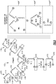
Figure 5 schematically illustrates another exemplary generator control unit including a transformer having a primary winding corresponding to three secondary windings. -
Figure 1 schematically illustrates anaircraft 10 including apower distribution system 20 for distributing electrical power to multiple onboardelectrical systems 30. The electrical power is generated by multipleonboard generators 40, each of which includes an internal permanent magnet generator. While illustrated herein as including threegenerators 40, one of skill in the art will appreciate that the system described herein can be expanded to include any number ofadditional generators 40 without requiring substantial alterations to the disclosed system. - Each of the
generators 40 receives rotational power from corresponding aircraft components, and has a unique internal permanent magnet generator construction dictated by its location within theaircraft 10 and the component driving the rotation of thegenerator 40. Output power generated by eachgenerator 40 is provided to thepower distribution system 20. - As a result of the distinct output power capabilities and operating requirements of each
generator 40, each of thegenerators 40 includes agenerator control unit 50. Thegenerator control unit 50 draws internal control power from the corresponding permanent magnet generator, and regulates the output power provided by thegenerator 40 in order to ensure that the output power is within the range of power that can be distributed via thepower distribution system 20. In some examples, thegenerator control unit 50 can further include a computerized component assisting the operation and control of thegenerator 40 including thegenerator control unit 50 according to any known generator control configuration. - In existing aircraft power generation systems, each permanent magnet generator has a distinct part number and a distinct generator control unit configuration due to the distinct power output capabilities of a given generator on the aircraft. However, it is common for the
generator control units 50 to have a single part number, and utilize a single standardized configuration across all of thegenerators 40. When all of the permanent magnet generators have power capabilities within a reasonable range of the power capabilities of each other permanent magnet generator, utilizing a single internal transformer within the correspondinggenerator control units 50 for providing the internal power to the permanent magnet generator is an operable solution. However, in some cases the output voltage capabilities of the permanent magnet generators can be too far varied resulting in anaircraft 10 where agenerator control unit 50 having a single internal transformer configuration cannot be utilized for all permanent magnet generators included within thegenerators 40. - With continued reference to
Figure 1 , and with like numerals indicating like elements,Figure 2 schematically illustrates an exemplarygenerator control unit 50 that can be universally used in all of thegenerators 40, despite the extreme variation in power capabilities, according to one embodiment. Thegenerator control unit 50 has multiple threephase inputs input aircraft 10. When multiple permanent magnet generators have the same characteristics (i.e. output power within the same voltage and current scale) asingle input generators 40 on each of the aircraft engines have the same power requirements, only a singlegenerator control unit 50 input is required to cover that configuration. - Within the
generator control unit 50 is atransformer 120. Theexemplary transformer 120 includes a multi-configurationprimary winding 122 paired with a singlesecondary winding 124. In alternative examples, multiplesecondary windings 124 can be utilized according to any known transformer configuration. Thesewindings transformer 120 receives power from the corresponding permanent magnet generator at one of theinputs primary winding 122 at theinput generator control unit 50 is drawn from the corresponding permanent magnet generator, and allows for the regulation and control of the output power generated by thegenerator 40. - The generator output power is then provided to the
power distribution system 20. The multiple configurationprimary winding 122 includes multiple connections, each of which is configured to pass connected power through a corresponding number of turns. The number of turns at eachinput - To achieve this, each
input primary winding 122. The multi configuration nature of the primary winding 122 allows a single primary winding 122 structure to receive input power at different voltage and current levels, and transform the power to a corresponding desired internal operating power through the single secondary winding 124. In this way, identicalgenerator control units 50 can be used throughout all of thegenerators 40 by connecting eachgenerator control unit 50 to its corresponding permanent magnet generator via thecorrect inputs - In some examples, such as the example illustrated in
Figure 3 , the multi configurations are achieved via the use of multiple parallel primary windings, each paired with the secondary winding(s) 124 and each having a distinct number of winding turns. In alternative examples, a single primary winding 122 with multiple taps can be utilized, as in the example ofFigure 4 . In the alternative example, each tap corresponds to a distinct number of turns on a given phase leg. - With continued reference to
Figures 1 and2 , and with like numerals indicating like elements,Figure 3 schematically illustrates an exemplarygenerator control unit 50 including atransformer 220 having three parallelprimary windings primary windings magnet generator inputs - Each of the phase legs has a set number of turns, corresponding to the transformation ratio required at the given
input generator 40, the power from the internal permanent magnet generator is connected to theinput generators 40. In such examples a single parallel primary winding 222, 222', 222" connected to asingle input - The secondary winding 224 includes a single three
phase output 230 which provides internal operating power thegenerator control unit 50. - With continued reference to
Figures 1-3 ,Figure 4 schematically illustrates another examplegenerator control unit 50. As with thegenerator control unit 50 illustrated inFigure 3 , thegenerator control unit 50 ofFigure 4 includes a single secondary winding 324 that outputs three phases A, B, C to provide internal power to thegenerator control unit 50 and allow for thegenerator control unit 50 to regulate thecorresponding generator 40. The multi-configuration primary winding 322 is a single multi-tap winding 322. As used herein a multi-tap winding is an electrical winding with input connections at multiple points in the winding. The position of the tap on the phase leg determines how many turns of the primary winding 322 the power connected to that tap is passed through. - As is understood in the art, the ratio between the number of turns of the input winding that the power is passed through to the total number of turns on the output winding determines the scale of the power at the outputs A, B, C. In the illustrated example, each leg of the multi-tap winding 322 includes three
inputs generator control unit 50. In the illustrated example, theinnermost tap 362 passes the power through the least amount of turns, themiddle tap 364 passes the power through an intermediate number of turns, while theoutermost tap 366 passes the power through all of the turns. In yet a further variation of the example ofFigure 4 , each segment A1, A2, A3, etc. of a given phase leg can be independent of each other segment. In such a configuration the segments can be jumped together at the corresponding inputs according to known jumping techniques allowing for one or more of the segments to be omitted. Such a configuration further expands on the number of configurations a given input winding 322 can include, and is referred to as a multiple isolated series winding. - Each of the
inputs taps permanent magnet generators 40 that could include thegenerator control unit 50. - By utilizing a single multi-tapped input winding within the
generator control unit 50, the weight of eachgenerator control unit 50, and thus the overall weight of theaircraft 10, can be reduced relative to previous examples. Further, when constructed with a standard set of known taps 362, 364, 366, thegenerator control unit 50 ofFigure 4 can be utilized in an "off the shelf' capacity, with a single generator control unit configuration being able to generate internal operating power using the generator control unit's 50 permanent magnet generator while installed in any givengenerator 40 within theaircraft 10. - In yet a further example, the structures of
Figure 3 andFigure 4 can be combined, and one or more of the parallelprimary windings Figure 4 . Such a configuration further can achieve some of the weight reduction benefits of the multi-tap configuration ofFigure 4 , while at the same time achieving some of the flexibility of the parallel winding configuration ofFigure 3 . - With continued reference to
Figures 1-4 ,Figure 5 schematically illustrates another specific exemplarygenerator control unit 50 including a transformer having a primary winding 422 corresponding to threesecondary windings 424', 424", 424'" (referred to collectively as secondary windings 424). While illustrated as windings in a wye configuration (secondary winding 424'), a delta winding (424") and a single winding (424"') one of skill in the art will appreciate that the windings can be any combination of the types including all one type of winding, a combination of two types of windings, or a combination of all three types of windings. - The illustrated primary winding 422 includes three
phase legs 470, each of which includes three isolated (floating) windings 472. In alternative examples two isolated (floating)windings 472, or any number greater than three can be utilized in place of the illustrated three isolated (floating) windings 472. Each of the isolated (floating)windings 472 includes afirst tap 474 and asecond tap 476. Thesecond tap 476 of one of the isolated (floating)windings 472 in eachleg 470 is connected to a center point of the wye configuration, and the isolated (floating) winding 472 includingcenter point tap 476 is always included in the transformer configuration. Each of the other isolated (floating)windings 472 in a givenleg 470 can be connected, or disconnected, by connecting asecond tap 476 of one isolated (floating) winding 472 to a first tap of the another isolated (floating) winding 472 in series, as illustrated viaconnectors 478 inFigure 5 . - The
connectors 478 are, in some examples, permanent or semi-permanent jumpers connected during an installation of thegenerator control unit 50. Theconnectors 478 are, in other examples, controlled switches that are controlled via thegenerator control unit 50. When controlled switches are utilized, active control of the transformer within thegenerator control unit 50 can be utilized to accommodate different operational modes (e.g. different rotational speeds) of the permanent magnet generator and further ensure a net zero flux impact to the core. - Utilization of multiple isolated (floating)
windings 472 in the primary winding 422 reduces parasitic capacitance and inductances that can be further compounded by the coupling of out-of-phase voltages from the other input phases. Such parasitic capacitance and inductance can result in harmonic noise, higher voltages, including higher voltage transients, or sub harmonics that can excite mechanical resonance. - While each of the
generator control units 50 illustrated herein includes a schematic permanent magnet generator control unit transformer, one of skill in the art will appreciate that the generator control units include all other conventional generator control unit circuitry. The conventional aspects of thegenerator control unit 50 are omitted from the illustration and discussion in the interest of brevity and clarity. - While illustrated in the provided examples as three distinct three-phase permanent magnet generator connections to the generator control unit, one of skill in the art will appreciate that any balanced number of phases could be included in each of the permanent magnet generators, and any number permanent magnet generator configurations could be used with minimal alterations to the illustrated configuration.
- It is further understood that any of the above described concepts can be used alone or in combination with any or all of the other above described concepts. Although an embodiment of this invention has been disclosed, a worker of ordinary skill in this art would recognize that certain modifications would come within the scope of this invention, the scope of which is defined by the claims.
Claims (15)
- A generator control unit comprising:a plurality of permanent magnet generator, PMG, inputs (110,112,114);a transformer (120) including a multi-configuration input winding (122) and at least one output winding (124);each PMG input in the plurality of PMG inputs being connected to the multi-configuration input winding at a corresponding input winding input.
- The generator control unit of claim 1, wherein the multi-configuration input winding is a multi-tapped primary winding having a plurality of phase legs, or wherein the multi-configuration input winding is a multiple isolated series winding, or wherein the multi-configuration input winding includes a plurality of parallel primary windings, each of the parallel primary windings having a distinct parallel primary winding configuration, and preferably wherein the distinct parallel primary winding configuration includes a distinct number of winding turns from each other parallel primary winding, and preferably wherein each of the parallel winding configurations corresponds to at least one PMG input in the plurality of PMG inputs.
- The generator control unit of claim 1, wherein the at least one output winding includes a single output winding, or wherein the at least one output winding includes a plurality of output windings.
- The generator control unit of claim 1, wherein the multi-configuration input winding includes a plurality of phase legs (470), with each phase leg comprising an identical number of isolated (floating) windings (472).
- The generator control unit of claim 4, wherein a configuration of the isolated (floating) windings in each phase is actively controlled.
- The generator control unit of claim 4 or 5, wherein a configuration of the isolated (floating) windings in each phase is wired external to the multi-configuration input winding.
- An aircraft electrical system comprising:a plurality of generators (40), each of said generators including a corresponding permanent magnet generator, PMG, and a corresponding uniform generator control unit (50), and being connected to a power distribution system (20); andeach uniform generator control unit being identical to each other uniform generator control unit and including a transformer (50) having a multi-configuration input winding (122) and at least one output winding (124), wherein each PMG is connected to a single configuration of the corresponding multi-configuration input winding.
- The aircraft electrical system of claim 7, wherein the multi-configuration input winding is a single winding having a plurality of phase legs (470), with each phase leg including a plurality of input taps (474), or wherein the multi-configuration input winding is a multiple isolated series winding.
- The aircraft electrical system of claim 8 wherein at least two of the PMGs are connected to a corresponding first input tap in the plurality of input taps of the corresponding generator control unit in a first configuration, and wherein at least one other of the PMGs in the plurality of PMGs is connected to the corresponding first input tap in the corresponding generator control unit in a second configuration.
- The aircraft electrical system of claim 7, 8 or 9, wherein the multi-configuration input winding is a plurality of parallel input windings, and wherein each input winding in the plurality of parallel input windings has a distinct number of turns per leg.
- The aircraft electrical system of claim 10, wherein at least one of the parallel input windings in the plurality of parallel input windings is a multi-tapped input winding.
- The aircraft electrical system of claim 10 or 11, wherein each uniform generator control unit includes a number of inputs, and the number of inputs is less than the number of permanent magnet generators including the uniform generator control units.
- A method for standardizing aircraft components comprising:providing a uniform generator control unit to each generator on an aircraft, the uniform generator control unit including a plurality of permanent magnet generator (PMG) inputs, a transformer including a multi-configuration input winding and at least one output winding, and each PMG input in the plurality of PMG inputs being connected to the multi-configuration input winding at a corresponding input winding input; andpassing power from a PMG through a corresponding configuration of the multi-configuration transformer, thereby generating operational power for the corresponding generator control unit and the corresponding generator.
- The method of claim 13, wherein passing power through the corresponding configuration of the multi-configuration transformer comprises passing power from the PMG corresponding through a distinct parallel input winding of the multi-configuration transformer.
- The method of claim 13, wherein passing power through the corresponding configuration of the multi-configuration transformer comprises passing power from the permanent magnet generator in the plurality of PMGs to a distinct input tap at each phase leg of the single transformer.
Applications Claiming Priority (1)
| Application Number | Priority Date | Filing Date | Title |
|---|---|---|---|
| US15/982,454 US10981667B2 (en) | 2018-05-17 | 2018-05-17 | Uniform generator control unit including multiple permanent magnet generator inputs |
Publications (2)
| Publication Number | Publication Date |
|---|---|
| EP3570402A1 true EP3570402A1 (en) | 2019-11-20 |
| EP3570402B1 EP3570402B1 (en) | 2023-04-05 |
Family
ID=66554287
Family Applications (1)
| Application Number | Title | Priority Date | Filing Date |
|---|---|---|---|
| EP19174682.5A Active EP3570402B1 (en) | 2018-05-17 | 2019-05-15 | Uniform generator control unit including multiple permanent magnet generator inputs |
Country Status (2)
| Country | Link |
|---|---|
| US (1) | US10981667B2 (en) |
| EP (1) | EP3570402B1 (en) |
Families Citing this family (4)
| Publication number | Priority date | Publication date | Assignee | Title |
|---|---|---|---|---|
| CN112802674B (en) * | 2020-12-30 | 2023-04-07 | 合肥博微田村电气有限公司 | Multi-input selection three-phase isolation transformer |
| US11527975B2 (en) | 2021-03-08 | 2022-12-13 | Hamilton Sundstrand Corporation | Low-power bias supply to facilitate the low-RPM startup of three-phase AC aircraft generators |
| FR3124648B1 (en) * | 2021-06-29 | 2023-12-08 | Schneider Electric Ind Sas | Power supply system |
| US11923800B2 (en) | 2022-05-06 | 2024-03-05 | Hamilton Sundstrand Corporation | Saturable reactors in generator control units |
Citations (4)
| Publication number | Priority date | Publication date | Assignee | Title |
|---|---|---|---|---|
| US20010048356A1 (en) * | 2000-01-12 | 2001-12-06 | Transformers And Phase Shifters, Inc. | Method and apparatus for providing selectable output voltages |
| US8687394B2 (en) * | 2008-10-28 | 2014-04-01 | Champion Aerospace Llc | Aircraft power supply and method of operating the same |
| EP3168950A1 (en) * | 2015-11-11 | 2017-05-17 | Airbus Operations, S.L. | Electric power distribution system for an aircraft |
| EP3188335A1 (en) * | 2015-12-30 | 2017-07-05 | Openhydro IP Limited | Electrical generator unit |
Family Cites Families (7)
| Publication number | Priority date | Publication date | Assignee | Title |
|---|---|---|---|---|
| GB885514A (en) * | 1957-01-18 | 1961-12-28 | Union Carbide Corp | Acetylene transition metal carbonyl derivatives |
| US4968926A (en) * | 1989-10-25 | 1990-11-06 | Sundstrand Corporation | Power conversion system with stepped waveform DC to AC converter having prime mover start capability |
| US5804953A (en) * | 1995-08-03 | 1998-09-08 | Atlas Energy Systems, Inc. | Power converter for converting AC shore power to shipboard use |
| HUP1000054A3 (en) * | 2010-01-26 | 2012-08-28 | Gradix Holdings Ltd | Ac voltage converter and switching equipment |
| DE102010061721A1 (en) * | 2010-11-22 | 2012-05-24 | Airbus Operations Gmbh | Energy supply network for an aerospace vehicle, method for supplying electrical consumers with energy and aircraft or spacecraft |
| US20140197681A1 (en) * | 2012-07-30 | 2014-07-17 | The Boeing Company | Electric system stabilizing system for aircraft |
| US20170359011A1 (en) | 2016-06-08 | 2017-12-14 | Hamilton Sundstrand Corporation | Reconfigurable multi-permanent magnet generator based power generating system |
-
2018
- 2018-05-17 US US15/982,454 patent/US10981667B2/en active Active
-
2019
- 2019-05-15 EP EP19174682.5A patent/EP3570402B1/en active Active
Patent Citations (4)
| Publication number | Priority date | Publication date | Assignee | Title |
|---|---|---|---|---|
| US20010048356A1 (en) * | 2000-01-12 | 2001-12-06 | Transformers And Phase Shifters, Inc. | Method and apparatus for providing selectable output voltages |
| US8687394B2 (en) * | 2008-10-28 | 2014-04-01 | Champion Aerospace Llc | Aircraft power supply and method of operating the same |
| EP3168950A1 (en) * | 2015-11-11 | 2017-05-17 | Airbus Operations, S.L. | Electric power distribution system for an aircraft |
| EP3188335A1 (en) * | 2015-12-30 | 2017-07-05 | Openhydro IP Limited | Electrical generator unit |
Also Published As
| Publication number | Publication date |
|---|---|
| EP3570402B1 (en) | 2023-04-05 |
| US20190352017A1 (en) | 2019-11-21 |
| US10981667B2 (en) | 2021-04-20 |
Similar Documents
| Publication | Publication Date | Title |
|---|---|---|
| EP3570402B1 (en) | Uniform generator control unit including multiple permanent magnet generator inputs | |
| US10396682B2 (en) | Method for operating an electrical network | |
| KR101209613B1 (en) | Method for providing magnetic coupler and device for providing electric dipole | |
| US20210197676A1 (en) | Method and apparatus for charging an energy store | |
| US7772953B2 (en) | Symmetrical auto transformer delta topologies | |
| US7772954B2 (en) | Symmetrical auto transformer wye topologies | |
| US7796413B2 (en) | AC to DC Power converter for aerospace applications | |
| US10921403B2 (en) | Systems and methods for providing gradient power for an MRI system | |
| EP2670045B1 (en) | Dual generator system | |
| US20120049805A1 (en) | Fault ride through switch for power generation system | |
| US12237677B2 (en) | Power-electronic device comprising a transformer unit and method | |
| US20170353049A1 (en) | System for converting electrical energy supplied by a network and a conversion method implemented by means of such a conversion system | |
| EP3070725B1 (en) | Multi-phase autotransformer | |
| EP3493384A1 (en) | System of input current sharing for compact architecture in a power converter | |
| US10050548B2 (en) | No-break power transfer | |
| US9673620B2 (en) | Energy supply network; method and aircraft or spacecraft | |
| EP2593946B1 (en) | A multiphase transformer rectifier unit | |
| US20150256099A1 (en) | Six-Phase Supplied Transformer Rectifier Unit | |
| US7859376B2 (en) | Zigzag autotransformer apparatus and methods | |
| US9509237B2 (en) | AC motor with stator winding tap and methods for starting an AC motor with a variable speed drive | |
| US11120939B2 (en) | Ten-phase auto transformer rectifier unit | |
| US1926689A (en) | Transformer system | |
| US11277075B2 (en) | Power system architecture with reduced common mode voltage | |
| EP4178095A1 (en) | Dual saturable reactor power supply | |
| WO2022148545A1 (en) | Transformer and electronic device |
Legal Events
| Date | Code | Title | Description |
|---|---|---|---|
| PUAI | Public reference made under article 153(3) epc to a published international application that has entered the european phase |
Free format text: ORIGINAL CODE: 0009012 |
|
| STAA | Information on the status of an ep patent application or granted ep patent |
Free format text: STATUS: THE APPLICATION HAS BEEN PUBLISHED |
|
| AK | Designated contracting states |
Kind code of ref document: A1 Designated state(s): AL AT BE BG CH CY CZ DE DK EE ES FI FR GB GR HR HU IE IS IT LI LT LU LV MC MK MT NL NO PL PT RO RS SE SI SK SM TR |
|
| AX | Request for extension of the european patent |
Extension state: BA ME |
|
| STAA | Information on the status of an ep patent application or granted ep patent |
Free format text: STATUS: REQUEST FOR EXAMINATION WAS MADE |
|
| 17P | Request for examination filed |
Effective date: 20191202 |
|
| RBV | Designated contracting states (corrected) |
Designated state(s): AL AT BE BG CH CY CZ DE DK EE ES FI FR GB GR HR HU IE IS IT LI LT LU LV MC MK MT NL NO PL PT RO RS SE SI SK SM TR |
|
| STAA | Information on the status of an ep patent application or granted ep patent |
Free format text: STATUS: EXAMINATION IS IN PROGRESS |
|
| 17Q | First examination report despatched |
Effective date: 20210622 |
|
| GRAP | Despatch of communication of intention to grant a patent |
Free format text: ORIGINAL CODE: EPIDOSNIGR1 |
|
| STAA | Information on the status of an ep patent application or granted ep patent |
Free format text: STATUS: GRANT OF PATENT IS INTENDED |
|
| RIC1 | Information provided on ipc code assigned before grant |
Ipc: H02P 101/30 20150101ALN20221012BHEP Ipc: H01F 29/02 20060101ALI20221012BHEP Ipc: B64D 33/00 20060101ALI20221012BHEP Ipc: H02P 9/00 20060101ALI20221012BHEP Ipc: H02J 3/46 20060101AFI20221012BHEP |
|
| INTG | Intention to grant announced |
Effective date: 20221026 |
|
| GRAS | Grant fee paid |
Free format text: ORIGINAL CODE: EPIDOSNIGR3 |
|
| GRAA | (expected) grant |
Free format text: ORIGINAL CODE: 0009210 |
|
| STAA | Information on the status of an ep patent application or granted ep patent |
Free format text: STATUS: THE PATENT HAS BEEN GRANTED |
|
| AK | Designated contracting states |
Kind code of ref document: B1 Designated state(s): AL AT BE BG CH CY CZ DE DK EE ES FI FR GB GR HR HU IE IS IT LI LT LU LV MC MK MT NL NO PL PT RO RS SE SI SK SM TR |
|
| REG | Reference to a national code |
Ref country code: GB Ref legal event code: FG4D |
|
| REG | Reference to a national code |
Ref country code: CH Ref legal event code: EP |
|
| REG | Reference to a national code |
Ref country code: AT Ref legal event code: REF Ref document number: 1558986 Country of ref document: AT Kind code of ref document: T Effective date: 20230415 |
|
| REG | Reference to a national code |
Ref country code: DE Ref legal event code: R096 Ref document number: 602019027098 Country of ref document: DE |
|
| REG | Reference to a national code |
Ref country code: IE Ref legal event code: FG4D |
|
| REG | Reference to a national code |
Ref country code: LT Ref legal event code: MG9D |
|
| REG | Reference to a national code |
Ref country code: NL Ref legal event code: MP Effective date: 20230405 |
|
| REG | Reference to a national code |
Ref country code: AT Ref legal event code: MK05 Ref document number: 1558986 Country of ref document: AT Kind code of ref document: T Effective date: 20230405 |
|
| PG25 | Lapsed in a contracting state [announced via postgrant information from national office to epo] |
Ref country code: NL Free format text: LAPSE BECAUSE OF FAILURE TO SUBMIT A TRANSLATION OF THE DESCRIPTION OR TO PAY THE FEE WITHIN THE PRESCRIBED TIME-LIMIT Effective date: 20230405 |
|
| PG25 | Lapsed in a contracting state [announced via postgrant information from national office to epo] |
Ref country code: SE Free format text: LAPSE BECAUSE OF FAILURE TO SUBMIT A TRANSLATION OF THE DESCRIPTION OR TO PAY THE FEE WITHIN THE PRESCRIBED TIME-LIMIT Effective date: 20230405 Ref country code: PT Free format text: LAPSE BECAUSE OF FAILURE TO SUBMIT A TRANSLATION OF THE DESCRIPTION OR TO PAY THE FEE WITHIN THE PRESCRIBED TIME-LIMIT Effective date: 20230807 Ref country code: NO Free format text: LAPSE BECAUSE OF FAILURE TO SUBMIT A TRANSLATION OF THE DESCRIPTION OR TO PAY THE FEE WITHIN THE PRESCRIBED TIME-LIMIT Effective date: 20230705 Ref country code: ES Free format text: LAPSE BECAUSE OF FAILURE TO SUBMIT A TRANSLATION OF THE DESCRIPTION OR TO PAY THE FEE WITHIN THE PRESCRIBED TIME-LIMIT Effective date: 20230405 Ref country code: AT Free format text: LAPSE BECAUSE OF FAILURE TO SUBMIT A TRANSLATION OF THE DESCRIPTION OR TO PAY THE FEE WITHIN THE PRESCRIBED TIME-LIMIT Effective date: 20230405 |
|
| PG25 | Lapsed in a contracting state [announced via postgrant information from national office to epo] |
Ref country code: RS Free format text: LAPSE BECAUSE OF FAILURE TO SUBMIT A TRANSLATION OF THE DESCRIPTION OR TO PAY THE FEE WITHIN THE PRESCRIBED TIME-LIMIT Effective date: 20230405 Ref country code: PL Free format text: LAPSE BECAUSE OF FAILURE TO SUBMIT A TRANSLATION OF THE DESCRIPTION OR TO PAY THE FEE WITHIN THE PRESCRIBED TIME-LIMIT Effective date: 20230405 Ref country code: LV Free format text: LAPSE BECAUSE OF FAILURE TO SUBMIT A TRANSLATION OF THE DESCRIPTION OR TO PAY THE FEE WITHIN THE PRESCRIBED TIME-LIMIT Effective date: 20230405 Ref country code: LT Free format text: LAPSE BECAUSE OF FAILURE TO SUBMIT A TRANSLATION OF THE DESCRIPTION OR TO PAY THE FEE WITHIN THE PRESCRIBED TIME-LIMIT Effective date: 20230405 Ref country code: IS Free format text: LAPSE BECAUSE OF FAILURE TO SUBMIT A TRANSLATION OF THE DESCRIPTION OR TO PAY THE FEE WITHIN THE PRESCRIBED TIME-LIMIT Effective date: 20230805 Ref country code: HR Free format text: LAPSE BECAUSE OF FAILURE TO SUBMIT A TRANSLATION OF THE DESCRIPTION OR TO PAY THE FEE WITHIN THE PRESCRIBED TIME-LIMIT Effective date: 20230405 Ref country code: GR Free format text: LAPSE BECAUSE OF FAILURE TO SUBMIT A TRANSLATION OF THE DESCRIPTION OR TO PAY THE FEE WITHIN THE PRESCRIBED TIME-LIMIT Effective date: 20230706 Ref country code: AL Free format text: LAPSE BECAUSE OF FAILURE TO SUBMIT A TRANSLATION OF THE DESCRIPTION OR TO PAY THE FEE WITHIN THE PRESCRIBED TIME-LIMIT Effective date: 20230405 |
|
| PG25 | Lapsed in a contracting state [announced via postgrant information from national office to epo] |
Ref country code: FI Free format text: LAPSE BECAUSE OF FAILURE TO SUBMIT A TRANSLATION OF THE DESCRIPTION OR TO PAY THE FEE WITHIN THE PRESCRIBED TIME-LIMIT Effective date: 20230405 |
|
| REG | Reference to a national code |
Ref country code: CH Ref legal event code: PL |
|
| REG | Reference to a national code |
Ref country code: DE Ref legal event code: R097 Ref document number: 602019027098 Country of ref document: DE |
|
| PG25 | Lapsed in a contracting state [announced via postgrant information from national office to epo] |
Ref country code: SK Free format text: LAPSE BECAUSE OF FAILURE TO SUBMIT A TRANSLATION OF THE DESCRIPTION OR TO PAY THE FEE WITHIN THE PRESCRIBED TIME-LIMIT Effective date: 20230405 |
|
| PG25 | Lapsed in a contracting state [announced via postgrant information from national office to epo] |
Ref country code: MC Free format text: LAPSE BECAUSE OF FAILURE TO SUBMIT A TRANSLATION OF THE DESCRIPTION OR TO PAY THE FEE WITHIN THE PRESCRIBED TIME-LIMIT Effective date: 20230405 |
|
| REG | Reference to a national code |
Ref country code: BE Ref legal event code: MM Effective date: 20230531 |
|
| PG25 | Lapsed in a contracting state [announced via postgrant information from national office to epo] |
Ref country code: SM Free format text: LAPSE BECAUSE OF FAILURE TO SUBMIT A TRANSLATION OF THE DESCRIPTION OR TO PAY THE FEE WITHIN THE PRESCRIBED TIME-LIMIT Effective date: 20230405 Ref country code: SK Free format text: LAPSE BECAUSE OF FAILURE TO SUBMIT A TRANSLATION OF THE DESCRIPTION OR TO PAY THE FEE WITHIN THE PRESCRIBED TIME-LIMIT Effective date: 20230405 Ref country code: RO Free format text: LAPSE BECAUSE OF FAILURE TO SUBMIT A TRANSLATION OF THE DESCRIPTION OR TO PAY THE FEE WITHIN THE PRESCRIBED TIME-LIMIT Effective date: 20230405 Ref country code: MC Free format text: LAPSE BECAUSE OF FAILURE TO SUBMIT A TRANSLATION OF THE DESCRIPTION OR TO PAY THE FEE WITHIN THE PRESCRIBED TIME-LIMIT Effective date: 20230405 Ref country code: LU Free format text: LAPSE BECAUSE OF NON-PAYMENT OF DUE FEES Effective date: 20230515 Ref country code: LI Free format text: LAPSE BECAUSE OF NON-PAYMENT OF DUE FEES Effective date: 20230531 Ref country code: EE Free format text: LAPSE BECAUSE OF FAILURE TO SUBMIT A TRANSLATION OF THE DESCRIPTION OR TO PAY THE FEE WITHIN THE PRESCRIBED TIME-LIMIT Effective date: 20230405 Ref country code: DK Free format text: LAPSE BECAUSE OF FAILURE TO SUBMIT A TRANSLATION OF THE DESCRIPTION OR TO PAY THE FEE WITHIN THE PRESCRIBED TIME-LIMIT Effective date: 20230405 Ref country code: CZ Free format text: LAPSE BECAUSE OF FAILURE TO SUBMIT A TRANSLATION OF THE DESCRIPTION OR TO PAY THE FEE WITHIN THE PRESCRIBED TIME-LIMIT Effective date: 20230405 Ref country code: CH Free format text: LAPSE BECAUSE OF NON-PAYMENT OF DUE FEES Effective date: 20230531 |
|
| PLBE | No opposition filed within time limit |
Free format text: ORIGINAL CODE: 0009261 |
|
| STAA | Information on the status of an ep patent application or granted ep patent |
Free format text: STATUS: NO OPPOSITION FILED WITHIN TIME LIMIT |
|
| REG | Reference to a national code |
Ref country code: IE Ref legal event code: MM4A |
|
| 26N | No opposition filed |
Effective date: 20240108 |
|
| PG25 | Lapsed in a contracting state [announced via postgrant information from national office to epo] |
Ref country code: IE Free format text: LAPSE BECAUSE OF NON-PAYMENT OF DUE FEES Effective date: 20230515 |
|
| PG25 | Lapsed in a contracting state [announced via postgrant information from national office to epo] |
Ref country code: IE Free format text: LAPSE BECAUSE OF NON-PAYMENT OF DUE FEES Effective date: 20230515 |
|
| PG25 | Lapsed in a contracting state [announced via postgrant information from national office to epo] |
Ref country code: SI Free format text: LAPSE BECAUSE OF FAILURE TO SUBMIT A TRANSLATION OF THE DESCRIPTION OR TO PAY THE FEE WITHIN THE PRESCRIBED TIME-LIMIT Effective date: 20230405 |
|
| PG25 | Lapsed in a contracting state [announced via postgrant information from national office to epo] |
Ref country code: SI Free format text: LAPSE BECAUSE OF FAILURE TO SUBMIT A TRANSLATION OF THE DESCRIPTION OR TO PAY THE FEE WITHIN THE PRESCRIBED TIME-LIMIT Effective date: 20230405 Ref country code: IT Free format text: LAPSE BECAUSE OF FAILURE TO SUBMIT A TRANSLATION OF THE DESCRIPTION OR TO PAY THE FEE WITHIN THE PRESCRIBED TIME-LIMIT Effective date: 20230405 Ref country code: BE Free format text: LAPSE BECAUSE OF NON-PAYMENT OF DUE FEES Effective date: 20230531 |
|
| PG25 | Lapsed in a contracting state [announced via postgrant information from national office to epo] |
Ref country code: BG Free format text: LAPSE BECAUSE OF FAILURE TO SUBMIT A TRANSLATION OF THE DESCRIPTION OR TO PAY THE FEE WITHIN THE PRESCRIBED TIME-LIMIT Effective date: 20230405 |
|
| PG25 | Lapsed in a contracting state [announced via postgrant information from national office to epo] |
Ref country code: BG Free format text: LAPSE BECAUSE OF FAILURE TO SUBMIT A TRANSLATION OF THE DESCRIPTION OR TO PAY THE FEE WITHIN THE PRESCRIBED TIME-LIMIT Effective date: 20230405 |
|
| PGFP | Annual fee paid to national office [announced via postgrant information from national office to epo] |
Ref country code: DE Payment date: 20250423 Year of fee payment: 7 |
|
| PGFP | Annual fee paid to national office [announced via postgrant information from national office to epo] |
Ref country code: GB Payment date: 20250423 Year of fee payment: 7 |
|
| PGFP | Annual fee paid to national office [announced via postgrant information from national office to epo] |
Ref country code: FR Payment date: 20250423 Year of fee payment: 7 |
|
| PG25 | Lapsed in a contracting state [announced via postgrant information from national office to epo] |
Ref country code: CY Free format text: LAPSE BECAUSE OF FAILURE TO SUBMIT A TRANSLATION OF THE DESCRIPTION OR TO PAY THE FEE WITHIN THE PRESCRIBED TIME-LIMIT; INVALID AB INITIO Effective date: 20190515 |
|
| PG25 | Lapsed in a contracting state [announced via postgrant information from national office to epo] |
Ref country code: HU Free format text: LAPSE BECAUSE OF FAILURE TO SUBMIT A TRANSLATION OF THE DESCRIPTION OR TO PAY THE FEE WITHIN THE PRESCRIBED TIME-LIMIT; INVALID AB INITIO Effective date: 20190515 |
|
| PG25 | Lapsed in a contracting state [announced via postgrant information from national office to epo] |
Ref country code: TR Free format text: LAPSE BECAUSE OF FAILURE TO SUBMIT A TRANSLATION OF THE DESCRIPTION OR TO PAY THE FEE WITHIN THE PRESCRIBED TIME-LIMIT Effective date: 20230405 |
|
| P01 | Opt-out of the competence of the unified patent court (upc) registered |
Free format text: CASE NUMBER: UPC_APP_0017942_3570402/2025 Effective date: 20251217 |