EP3570387A1 - Cable connection system with cable fixation shell - Google Patents
Cable connection system with cable fixation shell Download PDFInfo
- Publication number
- EP3570387A1 EP3570387A1 EP18172626.6A EP18172626A EP3570387A1 EP 3570387 A1 EP3570387 A1 EP 3570387A1 EP 18172626 A EP18172626 A EP 18172626A EP 3570387 A1 EP3570387 A1 EP 3570387A1
- Authority
- EP
- European Patent Office
- Prior art keywords
- shell
- cable
- housing
- connection system
- insulation sleeve
- Prior art date
- Legal status (The legal status is an assumption and is not a legal conclusion. Google has not performed a legal analysis and makes no representation as to the accuracy of the status listed.)
- Granted
Links
Images


Classifications
-
- H—ELECTRICITY
- H01—ELECTRIC ELEMENTS
- H01R—ELECTRICALLY-CONDUCTIVE CONNECTIONS; STRUCTURAL ASSOCIATIONS OF A PLURALITY OF MUTUALLY-INSULATED ELECTRICAL CONNECTING ELEMENTS; COUPLING DEVICES; CURRENT COLLECTORS
- H01R13/00—Details of coupling devices of the kinds covered by groups H01R12/70 or H01R24/00 - H01R33/00
- H01R13/58—Means for relieving strain on wire connection, e.g. cord grip, for avoiding loosening of connections between wires and terminals within a coupling device terminating a cable
- H01R13/5804—Means for relieving strain on wire connection, e.g. cord grip, for avoiding loosening of connections between wires and terminals within a coupling device terminating a cable comprising a separate cable clamping part
- H01R13/5816—Means for relieving strain on wire connection, e.g. cord grip, for avoiding loosening of connections between wires and terminals within a coupling device terminating a cable comprising a separate cable clamping part for cables passing through an aperture in a housing wall, the separate part being captured between cable and contour of aperture
-
- H—ELECTRICITY
- H01—ELECTRIC ELEMENTS
- H01R—ELECTRICALLY-CONDUCTIVE CONNECTIONS; STRUCTURAL ASSOCIATIONS OF A PLURALITY OF MUTUALLY-INSULATED ELECTRICAL CONNECTING ELEMENTS; COUPLING DEVICES; CURRENT COLLECTORS
- H01R13/00—Details of coupling devices of the kinds covered by groups H01R12/70 or H01R24/00 - H01R33/00
- H01R13/46—Bases; Cases
- H01R13/502—Bases; Cases composed of different pieces
- H01R13/506—Bases; Cases composed of different pieces assembled by snap action of the parts
-
- H—ELECTRICITY
- H01—ELECTRIC ELEMENTS
- H01R—ELECTRICALLY-CONDUCTIVE CONNECTIONS; STRUCTURAL ASSOCIATIONS OF A PLURALITY OF MUTUALLY-INSULATED ELECTRICAL CONNECTING ELEMENTS; COUPLING DEVICES; CURRENT COLLECTORS
- H01R13/00—Details of coupling devices of the kinds covered by groups H01R12/70 or H01R24/00 - H01R33/00
- H01R13/46—Bases; Cases
- H01R13/52—Dustproof, splashproof, drip-proof, waterproof, or flameproof cases
- H01R13/5205—Sealing means between cable and housing, e.g. grommet
-
- H—ELECTRICITY
- H01—ELECTRIC ELEMENTS
- H01R—ELECTRICALLY-CONDUCTIVE CONNECTIONS; STRUCTURAL ASSOCIATIONS OF A PLURALITY OF MUTUALLY-INSULATED ELECTRICAL CONNECTING ELEMENTS; COUPLING DEVICES; CURRENT COLLECTORS
- H01R2201/00—Connectors or connections adapted for particular applications
- H01R2201/26—Connectors or connections adapted for particular applications for vehicles
Definitions
- the present invention relates to a cable connection system, a method of assembling such a cable connection system, the use of such a cable connection system, and a shell for attaching a housing to a cable.
- Cable are typically used to transfer energy and/or information, for example between different components provided in a car.
- electrical connectors are typically applied.
- a male-ended connector and a female-ended connector may thereby be connected, whereby the connection may be temporary or permanently.
- Connectors with electrical crimps are one type of such electrical connections.
- Crimp connectors are typically used to terminate stranded wires. Thereby, the wire may be inserted into a terminal, and the terminal may than be cold-welded onto the wire. The terminal may be connected to a respective counter-connector.
- a connector may comprise a housing, which may house one or more wires, and may be adapted to be secured to a housing of the respective counter-connector, or to a supporting structure, for example.
- crimp metal ferrules are typically used. Thereby, a metal ferrule may be crimped on a cable braid, using a suitable crimping tool. Afterwards, for mounting the housing, the housing may be arranged over the crimped metal ferrule, or the metal ferrule with the cable may be inserted into the housing.
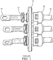
- Figure 1 shows a cable connection system according to a prior art design.
- Terminals 30' are provided on cables 20', and crimp metals ferrules 10' are crimped on the cables 20'.
- a housing 40' is provided over the crimp metal ferrules 20', and a seal retainer 50' is further attached to the housing 40'.
- the prior art design has several drawbacks: As can be depicted from figure 1 , the terminals 30' have different orientations, as the prior art design does not provide for a fixed orientation of the terminals 30'. Further, the terminals 30' (and cables 20') can be pulled out of the housing, as the crimp metal ferrules 20' are not fastened to the housing 40'.
- the present invention relates to a cable connection system.
- the cable connection system may thereby comprise an electrical connector, which may be adapted to be connected to a respective counter-connector.
- the counter-connector may thereby also be part of the cable connection system.
- the cable connection system may thereby allow for a temporary or permanent electrical connection between the connectors.
- the cable connection system thereby comprises a cable having an insulation sleeve.
- the cable may be an electrical cable, having a wire insulated from its surroundings by means of the insulation sleeve.
- the insulation sleeve may be made of or comprise cloth, rubber, paper and/or plastic components.
- the cable may further comprise a dielectric insulator, and/or a metallic shield, for example.
- the cable connection system further comprises a closable plastic shell encompassing the cable.
- the shell may thus essentially be formed of a plastic material, wherein the plastic material of the shell may be harder and feature a higher tensile strength with regard to a plastic component of the insulation sleeve.
- the plastic shell is thereby closable, such that it may be closed around the cable.
- the shell Upon closing the shell around the cable, the shell is fixed thereon.
- the plastic shell may be provided in form of an interrupted ring, wherein a gap in the ring can be widened to place the cable inside the plastic shell, and wherein the gap can then be closed so that the shell essentially encompasses the cable.
- the open ends of the ring can then be interconnected, for example by a clip system, to prevent an unwanted removal of the cable from the shell.
- the plastic shell may be provided as a multi-part shell, wherein the shell may comprise two or more parts, which are interconnectable to be closed around the cable, and to thereby encompass the cable.
- the shell comprises inner protrusions for fixing the shell to the insulation sleeve of the cable.
- the shell features protrusions on the inner side of the shell, i.e. on the side facing the cable.
- the protrusions may extend towards the center of the cable.
- the protrusions can be of any suitable form, and can be, for example, ribs or (elongated) nubs.
- These inner protrusions of the shell thereby allow for fixing the shell to the insulation sleeve of the cable in a secure manner.
- the protrusions may fix the shell to the insulation sleeve by means of traction. When the shell is closed around the cable, the inner protrusions may act on the insulation sleeve of the cable, preventing displacement of the shell.
- the cable connection system comprises a housing attached to the shell.
- the housing may encompass the shell and the cable.
- the shell, the cable and the housing may be provided as individual parts.
- the housing is essentially attached to the cable.
- the plastic shell thus ensures for a proper attachment of the housing to the cable.
- the shell may comprise attaching means
- the housing may comprise respective counter attaching means.
- the attachment may be in a form-fitting manner, preventing a relative orientation of the housing to the shell.
- the shell is made of a plastic material, costs are reduced with regard to solutions were metal crimp ferrules are used.
- the inner protrusions of the shell provide for a secure fixation to the cable.
- the shell can be fixed to the cable in an easy, safe, reliable and resistant manner.
- the cable connection system is preferably an unshielded connector system.
- the cable may thereby be free of a cable braid.
- the use of the plastic shell is of particular advantage, as the plastic shell it can be provided at different sizes at low cost. No advanced crimping equipment is required, as a plastic shell at any size can be easily provided at and fixed to the cable.
- the shell comprises at least two shell-parts.
- the shell may be provided as multi-part shell. Each shell-part may thereby partially encompass the cable.
- the shell-parts may be interconnected in order to close the shell-parts around the cable.
- the shell comprises two half-shells, which each cover one half of the cable.
- the shell-parts (or half-shells) may thereby be assembled together by means of a clip system.
- the shell-parts may be provided around the cable, and then assembled together in an easy manner.
- the clip system may comprise a hook and corresponding loop, wherein the hook can be inserted into the loop to interconnect the shell-parts. Thereby, the shell can be assembled around the cable, and if desired, also be un-assembled in an easy manner.
- the shell-parts or half-shells are equal in their structure.
- two structurally identical half-shells may be provided and assembled together around the cable. This additionally reduces the manufacturing costs, as only one injection mold is required for producing the multi-part plastic shell.
- an inner diameter of the shell is smaller than an outer diameter of the cable at an area free of the shell.
- the cable may have an outer diameter which is larger than an outer diameter of the cable at an area covered by the shell. This allows for properly fixing the shell to the cable.
- the shell at least partially squeezes the insulation sleeve of the cable.
- the inner protrusions of the shell may squeeze the insulation sleeve of the cable in order to fix the shell to the cable in a safe manner, preventing a displacement of the shell along the cable.
- the person skilled in the art understands to choose a proper material for the plastic shell, or at least for the inner protrusions, in order to allow for squeezing the insulation sleeve of the cable.
- the inner protrusions of the shell are inner ribs, which encompass the cable.
- the inner ribs may thereby form rings around the cable, when the shell is fixed to the cable. This structure provides for a particular strong fixation of the shell to the cable, effectively preventing a displacement of the shell along the cable.
- the shell has outer protrusions, preferably outer ribs, which at least partially engage the housing.
- the outer protrusions may extend along a main direction of the cable, i.e. along the cable itself. This provides for a particular strong attachment of the housing to the shell in a rotation-secure manner, as the interplay of the elongated ribs with the housing prevents a rotation of the housing around the cable.
- the housing has recesses, which at least partially receive the outer protrusions of the shell. Due to the interplay of the outer protrusions of the shell with the recesses of the housing, a proper orientation of the cable with respect to the housing can be ensured. A rotation of the cable relative to the housing is thereby efficiently prevented.
- the recesses of the housing and the outer protrusions of the shell are aligned at least partially in a form-fitting manner.
- the form-fit may prevent a rotation of the housing around the shell.
- the recesses of the housing and the outer protrusions of the shell may thereby be keyed.
- This interplay of the housing and shell may prevent attachment of the housing to the shell except when the shell and the housing are provided in a desired orientation relative to each other.
- a misalignment of the cable with regard to the housing upon assembly is prevented.
- the recesses of the housing and the outer protrusions of the shell are keyed such that the shell can be arranged inside the housing in four or less orientations, further preferred in three or less orientations, further preferred in two or less orientations and most preferred in only a single orientation.
- the shell can be arranged inside the housing in four or less orientations, further preferred in three or less orientations, further preferred in two or less orientations and most preferred in only a single orientation.
- the shell has a collar extending from the shell, and the housing has one or more blocking ribs, which engage the collar of the shell.
- the blocking ribs may thereby engage the collar of the shell along the main direction of the cable.
- the system further comprises a seal retainer engaging the collar of the shell.
- the seal retainer may thereby be attached to the housing and/or to the cable, and the seal retainer may engage the collar of the shell on a side opposite to the side which is engaged by the blocking ribs of the housing.
- the seal retainer may be provided together with a seal, which is held in position by the seal retained.
- the seal may be provided to protect the shell.
- the seal retainer may engage the collar of the shell to come into blocking contact therewith if pushing and/or pulling forces are applied to the cable.
- the system further comprises a terminal attached to the cable.
- the terminal may thereby be crimped to the cable, for example to an end of the wire, in proximity to the shell fixed on the cable.
- the person skilled in the art understands that several cables, each provided with a shell, may be provided in the housing.
- the invention further relates to a method of assembling a cable connection system according to the above.
- the method thereby comprises the steps of: Providing the cable with the insulation sleeve; fixing the plastic shell to the insulation sleeve, for example by interconnecting two plastic half-shells around the cable by closing a clip system; and attaching the housing to the shell.
- the housing can eventually be attached to the cable via the shell in an easy, low-cost, and secure manner.
- the present invention relates to the use of a cable connection system according to the above, in order to transfer energy and/or information.
- the cable connection system can, for example, be provided in an automotive vehicle, for transferring energy and/or information.
- the invention relates to a shell for attaching a housing to a cable.
- the shell is thereby formed of a plastic material, and is closable, as described above.
- the shell is closeable to essentially encompass the cable, as described above.
- the shell comprises inner protrusions for fixing the shell to a cable, and attaching means for attaching a housing to the shell.
- FIG. 2 presents a part of a shell of a cable connection system according to an embodiment of the present invention.
- a half-shell 10 is shown, which is of a plastic material, and is preferably free of metals.
- the half-shell 10 may thereby be produced by injection molding, as will be appreciated by the person skilled in the art.
- the half-shell 10 comprises outer ribs 11, which are provided in an elongated form and parallel to a main central axis of the half-shell 10.
- the half-shell 10 features a collar 12, which extends from one end of the shell, away from the main central axis of the half-shell 10.
- the half-shell 10 comprises a hook 13, which is part of a clip system for interconnecting several such half-shells 10, as will be further described below.
- FIG 3 illustrates two half-shells 10, which can be interconnected to form a shell of a cable connection system according to an embodiment of the present invention.
- Each one of the half-shells 10 may correspond to the half-shell 10 presented in figure 2 .
- the half-shells 10 in figure 3 are identical to each other.
- Each half-shell 10 is provided with a lash 15, which is located at a side opposite to the hook 13 described with regard to figure 2 .
- the two half-shells 10 can be arranged around a cable 20, and can then be interconnected and closed by means of the lash 15 and hook 13.
- the shell formed of the half-shells 10 can be closed around the cable 20.
- the design of identical half-shells 10 provided with the clip system allows for an easy assembly of the shell to the cable 20. As only one type of half-shells 10 is required, production and storage costs can be reduced.
- the half-shells 10 further feature inner ribs 14 facing the cable 20.
- the inner ribs 14 form rings around the cable 20.
- the provision of the inner ribs 14 allows for fixing the interconnected half-shells 10 to the cable 20, as the inner ribs 14 partially squeeze the cable 20 when the half-shells 10 are closed around the cable 20.
- a terminal 30 is provided at one end of the cable 20, adapted to be connected to a respective counter-terminal.
- Figure 4 illustrates the two half-shells 10 of figure 3 in the interconnected or closed state.
- the half-shells 10 of the closed shell encompass the cable 20.
- the shell thereby encompasses the cable 20, and is fixed to the cable 20 by means of the inner ribs 14.
- the inner ribs 14 partially squeeze an insulation sleeve of the cable 20, as will be described in more detail below.
- FIG. 5 illustrates a housing 40 attached to the shell described with reference to figure 4 .
- the housing 40 encompasses the shell 10, and thus also the cable 20.
- the housing 40 comprises a housing collar 42, which extends from the housing 40.
- locking means in form of a sliding ramp or hook 41 for locking a seal retainer to the housing 40 are provided.
- Figure 6 presents a cross-sectional view along the length of the cable with interconnected half-shells 10 attached thereto, according to the embodiment of figure 4 .
- the cable 20 comprises an electrical cable 21, and an insulation sleeve 22 which surrounds the electrical cable 21.
- the rings formed of the inner ribs 14 of the half-shells 10 extending around the cable 20 have an inner diameter which is smaller than the outer diameter of the cable 20 at a location free of the shell.
- the ribs 14 of the half-shells 10 squeeze the insulation sleeve 21 at the squeezing portions 23.
- the insulation sleeve 22 is partially compressed, and thus the shell eventually fixed to the cable 20 by traction. The shell is thereby protected against an undesired displacement along the length the cable 20. Cable movement relative to the shell, and thus relative to a housing 40 attached to the shell, is thereby blocked.
- Figure 7 presents a cross-sectional view through a cable connection system, according to the embodiment of figure 5 .
- the electrical cable 21 is encompassed by the insulation sleeve 22, which is in turn encompassed by the shell comprising the two inter-connected half-shells 10, which shell is in turn encompassed by the housing 40.
- the shell is fixed to the cable 20 by means of the inner-ribs 14 of the half-shells 10.
- the half-shells 10 are interconnected via the lashes 15 and hooks 13, which were described above with reference to figures 2 and 3 .
- the shell comprises outer ribs 11, as also described with reference to figure 2 .
- the housing 40 in turn comprises recesses 43, which receive the outer ribs 11 of the half-shells 10.
- the outer ribs 11 of the half-shells 10 and the recesses 43 of the housing 40 are thereby aligned in a form-fitting manner, preventing an undesired rotation of the housing 40 relative to the shell.
- the recesses 43 of the housing 40 and the outer ribs 11 of the half-shells 10 are keyed.
- the housing 40 can be provided on the shell only in one particular orientation, due to the keying.
- FIG. 8 illustrates a cross-sectional view along a cable connection system according to a further embodiment of the present invention, which to a large extend corresponds to the cable connection system described with reference to figures 5 and 7 .
- a shell 10 is provided on a cable 20, and fixed thereon by the inner ribs partially squeezing the insulation sleeve 21 of the cable 20, as also described above with regard to figure 6 .
- a housing 40 is attached to the shell.
- the housing 40 comprises a blocking rib 44, which engages the collar 12 of the half-shells 10.
- the collar 12 of the half-shells 10 comes into blocking contact with the blocking rib 44 of the housing 40.
- the housing 40 may be secured to a further device, the pulling forces can be efficiently transferred to the housing 40 and the further device. Hence, an undesired relative movement of the cable 20 can be prevented.
- a seal 60 is provided, which is secured by a seal retainer 50 to the housing 40.
- the seal retainer 50 is locked to the housing 40 by engaging the hook 41 provided on the housing 40.
- the seal retainer 50 comprises a tip 51, which engages in the collar 12 of the half-shells 10.
- the tip 51 of the seal retainer 50 thereby engages the collar 12 on a side opposed to the side engaged by the blocking rib 44 of the housing 40.
- the seal retainer 50 is connected to the housing 40 via the hook 41 of the housing 40, and as the housing 40 may be secured to a further device, such pushing forces can be efficiently transferred to the housing 40 and the further device. Hence, pulling and pushing forces acting on the cable 20 are efficiently transferred to the housing 40. Hence, the shell is blocked by the blocking rib 44 of the housing 40 on the one side, and by the tip 51 of the seal retainer 50 on the other side. Hence, the terminal 30 is eventually fixed in a proper position.
- the low-cost shell thus provides for properly fixing the cable 20 in the housing 40, thereby ensuring correct retention forces. Further, an undesired cable rotation inside the housing 40 is blocked, thereby ensuring a correct orientation of the terminal 30.
Landscapes
- Details Of Connecting Devices For Male And Female Coupling (AREA)
Abstract
Description
- The present invention relates to a cable connection system, a method of assembling such a cable connection system, the use of such a cable connection system, and a shell for attaching a housing to a cable.
- Cable are typically used to transfer energy and/or information, for example between different components provided in a car. In order to interconnect these components, electrical connectors are typically applied. A male-ended connector and a female-ended connector may thereby be connected, whereby the connection may be temporary or permanently. Connectors with electrical crimps are one type of such electrical connections. Crimp connectors are typically used to terminate stranded wires. Thereby, the wire may be inserted into a terminal, and the terminal may than be cold-welded onto the wire. The terminal may be connected to a respective counter-connector.
- A connector may comprise a housing, which may house one or more wires, and may be adapted to be secured to a housing of the respective counter-connector, or to a supporting structure, for example. For mounting the housing to the cable, crimp metal ferrules are typically used. Thereby, a metal ferrule may be crimped on a cable braid, using a suitable crimping tool. Afterwards, for mounting the housing, the housing may be arranged over the crimped metal ferrule, or the metal ferrule with the cable may be inserted into the housing.
-
Figure 1 shows a cable connection system according to a prior art design. Terminals 30' are provided on cables 20', and crimp metals ferrules 10' are crimped on the cables 20'. Furthermore, a housing 40' is provided over the crimp metal ferrules 20', and a seal retainer 50' is further attached to the housing 40'. The prior art design has several drawbacks: As can be depicted fromfigure 1 , the terminals 30' have different orientations, as the prior art design does not provide for a fixed orientation of the terminals 30'. Further, the terminals 30' (and cables 20') can be pulled out of the housing, as the crimp metal ferrules 20' are not fastened to the housing 40'. - For unshielded cables, i.e. cables without a braid, different ferrules must be used for different cable diameters. This increases the overall costs and also comes along with the necessity of advanced crimping equipment for crimping diverse ferrules. Furthermore, the terminal and cable are typically not provided in an orientation-fixed manner, so that a terminal may be provided relative to the housing in an incorrect orientation. In addition, when using the common metal ferrules, a proper fixation to the housing is typically only ensured in one direction, to withstand cable pulling. However, when cable pushing occurs, the fixation to the housing is typically of less strength.
- It is thus an objective of the present invention to provide a cable connection system which at least partially overcomes the above disadvantages. It is thereby a particular object of the present invention to provide a cable connection system of reduced cost, which allows for a proper orientation of a terminal with regard to a housing upon assembly, and/or which allows for a proper cable fixation inside the housing.
- These and other objects, which become apparent to the person skilled in the art upon reading the following description, are solved by the subject matter according to the independent claims.
- The present invention relates to a cable connection system. The cable connection system may thereby comprise an electrical connector, which may be adapted to be connected to a respective counter-connector. The counter-connector may thereby also be part of the cable connection system. The cable connection system may thereby allow for a temporary or permanent electrical connection between the connectors.
- The cable connection system thereby comprises a cable having an insulation sleeve. The person skilled in the art understands that the cable may be an electrical cable, having a wire insulated from its surroundings by means of the insulation sleeve. The insulation sleeve may be made of or comprise cloth, rubber, paper and/or plastic components. The person skilled in the art understands that the cable may further comprise a dielectric insulator, and/or a metallic shield, for example.
- The cable connection system further comprises a closable plastic shell encompassing the cable. The shell may thus essentially be formed of a plastic material, wherein the plastic material of the shell may be harder and feature a higher tensile strength with regard to a plastic component of the insulation sleeve.
- The plastic shell is thereby closable, such that it may be closed around the cable. Upon closing the shell around the cable, the shell is fixed thereon. For example, the plastic shell may be provided in form of an interrupted ring, wherein a gap in the ring can be widened to place the cable inside the plastic shell, and wherein the gap can then be closed so that the shell essentially encompasses the cable. The open ends of the ring can then be interconnected, for example by a clip system, to prevent an unwanted removal of the cable from the shell. Further for example, the plastic shell may be provided as a multi-part shell, wherein the shell may comprise two or more parts, which are interconnectable to be closed around the cable, and to thereby encompass the cable.
- The shell comprises inner protrusions for fixing the shell to the insulation sleeve of the cable. Thus, the shell features protrusions on the inner side of the shell, i.e. on the side facing the cable. The protrusions may extend towards the center of the cable. The protrusions can be of any suitable form, and can be, for example, ribs or (elongated) nubs. These inner protrusions of the shell thereby allow for fixing the shell to the insulation sleeve of the cable in a secure manner. For example, the protrusions may fix the shell to the insulation sleeve by means of traction. When the shell is closed around the cable, the inner protrusions may act on the insulation sleeve of the cable, preventing displacement of the shell.
- Furthermore, the cable connection system comprises a housing attached to the shell. Thus, the housing may encompass the shell and the cable. The shell, the cable and the housing may be provided as individual parts. As the housing is attached to the shell, and the shell is fixed to the cable, the housing is essentially attached to the cable. The plastic shell thus ensures for a proper attachment of the housing to the cable. For attaching the housing to the shell, the shell may comprise attaching means, and the housing may comprise respective counter attaching means. For example, the attachment may be in a form-fitting manner, preventing a relative orientation of the housing to the shell.
- As the shell is made of a plastic material, costs are reduced with regard to solutions were metal crimp ferrules are used. When closing the shell around the cable, to encompass the cable, the inner protrusions of the shell provide for a secure fixation to the cable. Hence, the shell can be fixed to the cable in an easy, safe, reliable and resistant manner. Thus, it is eventually possible to attach the housing to the cable in such an easy, safe, reliable and resistant manner.
- The cable connection system is preferably an unshielded connector system. The cable may thereby be free of a cable braid. Thus, for such unshielded cables, the use of the plastic shell is of particular advantage, as the plastic shell it can be provided at different sizes at low cost. No advanced crimping equipment is required, as a plastic shell at any size can be easily provided at and fixed to the cable.
- In a preferred embodiment, the shell comprises at least two shell-parts. Thus, the shell may be provided as multi-part shell. Each shell-part may thereby partially encompass the cable. The shell-parts may be interconnected in order to close the shell-parts around the cable. Preferably, the shell comprises two half-shells, which each cover one half of the cable. The shell-parts (or half-shells) may thereby be assembled together by means of a clip system. Thus, the shell-parts may be provided around the cable, and then assembled together in an easy manner. The clip system may comprise a hook and corresponding loop, wherein the hook can be inserted into the loop to interconnect the shell-parts. Thereby, the shell can be assembled around the cable, and if desired, also be un-assembled in an easy manner.
- Particularly preferred, the shell-parts or half-shells are equal in their structure. Thus, preferably, two structurally identical half-shells may be provided and assembled together around the cable. This additionally reduces the manufacturing costs, as only one injection mold is required for producing the multi-part plastic shell.
- Preferably, an inner diameter of the shell is smaller than an outer diameter of the cable at an area free of the shell. Thus, at an area not covered by the shell, the cable may have an outer diameter which is larger than an outer diameter of the cable at an area covered by the shell. This allows for properly fixing the shell to the cable.
- Preferably, the shell at least partially squeezes the insulation sleeve of the cable. Thus, by closing the shell around the cable, the inner protrusions of the shell may squeeze the insulation sleeve of the cable in order to fix the shell to the cable in a safe manner, preventing a displacement of the shell along the cable. The person skilled in the art understands to choose a proper material for the plastic shell, or at least for the inner protrusions, in order to allow for squeezing the insulation sleeve of the cable.
- Preferably, the inner protrusions of the shell are inner ribs, which encompass the cable. The inner ribs may thereby form rings around the cable, when the shell is fixed to the cable. This structure provides for a particular strong fixation of the shell to the cable, effectively preventing a displacement of the shell along the cable.
- In a preferred embodiment, the shell has outer protrusions, preferably outer ribs, which at least partially engage the housing. When provided as outer ribs, the outer protrusions may extend along a main direction of the cable, i.e. along the cable itself. This provides for a particular strong attachment of the housing to the shell in a rotation-secure manner, as the interplay of the elongated ribs with the housing prevents a rotation of the housing around the cable.
- Further preferred, the housing has recesses, which at least partially receive the outer protrusions of the shell. Due to the interplay of the outer protrusions of the shell with the recesses of the housing, a proper orientation of the cable with respect to the housing can be ensured. A rotation of the cable relative to the housing is thereby efficiently prevented.
- Further preferred, the recesses of the housing and the outer protrusions of the shell are aligned at least partially in a form-fitting manner. Thus, the form-fit may prevent a rotation of the housing around the shell. The recesses of the housing and the outer protrusions of the shell may thereby be keyed. This interplay of the housing and shell may prevent attachment of the housing to the shell except when the shell and the housing are provided in a desired orientation relative to each other. Thus, a misalignment of the cable with regard to the housing upon assembly is prevented. Preferably, the recesses of the housing and the outer protrusions of the shell are keyed such that the shell can be arranged inside the housing in four or less orientations, further preferred in three or less orientations, further preferred in two or less orientations and most preferred in only a single orientation. Thereby, a proper orientation of the cable with regard to the housing is ensured.
- In a further preferred embodiment, the shell has a collar extending from the shell, and the housing has one or more blocking ribs, which engage the collar of the shell. The blocking ribs may thereby engage the collar of the shell along the main direction of the cable. Thus, a force applied to the cable along the main direction of the cable can be transferred via the shell to the housing, as will be appreciated by the person skilled in the art. Thereby, a proper fixation of the cable inside the housing is ensured, and the durability of the cable connection system is increased. It will be appreciated that the blocking ribs of the housing may be provided on both sides of the collar of the shell, thus efficiently transferring cable pulling and cable pushing forces.
- Preferably, the system further comprises a seal retainer engaging the collar of the shell. The seal retainer may thereby be attached to the housing and/or to the cable, and the seal retainer may engage the collar of the shell on a side opposite to the side which is engaged by the blocking ribs of the housing. The seal retainer may be provided together with a seal, which is held in position by the seal retained. The seal may be provided to protect the shell. The seal retainer may engage the collar of the shell to come into blocking contact therewith if pushing and/or pulling forces are applied to the cable. Hence, the provision of the seal retainer provides for an easy assembly of the cable connection system while allowing for efficiently transferring both cable pulling and cable pushing forces to the housing.
- Preferably, the system further comprises a terminal attached to the cable. The terminal may thereby be crimped to the cable, for example to an end of the wire, in proximity to the shell fixed on the cable. The person skilled in the art understands that several cables, each provided with a shell, may be provided in the housing.
- The invention further relates to a method of assembling a cable connection system according to the above. The method thereby comprises the steps of: Providing the cable with the insulation sleeve; fixing the plastic shell to the insulation sleeve, for example by interconnecting two plastic half-shells around the cable by closing a clip system; and attaching the housing to the shell. Thereby, the housing can eventually be attached to the cable via the shell in an easy, low-cost, and secure manner.
- Furthermore, the present invention relates to the use of a cable connection system according to the above, in order to transfer energy and/or information. The cable connection system can, for example, be provided in an automotive vehicle, for transferring energy and/or information.
- Furthermore, the invention relates to a shell for attaching a housing to a cable. The shell is thereby formed of a plastic material, and is closable, as described above. In particular, the shell is closeable to essentially encompass the cable, as described above. Furthermore, the shell comprises inner protrusions for fixing the shell to a cable, and attaching means for attaching a housing to the shell. The person skilled in the art understands that the above details with regard to the shell described in context of the cable connection system also apply here with regard to the single shell.
- In the following, the present invention will be described in more detail with reference to the figures. Therein, similar elements are provided with same reference numbers. It shows:
-
Figure 1 : a cable connection system according to the prior art; -
Figure 2 : a part of a cable connection system according to an embodiment of the invention; -
Figures 3 and4 : parts of a cable connection system according to an embodiment of the invention; -
Figure 5 : a cable connection system according to an embodiment of the invention; -
Figure 6 : a cross-sectional view of parts of a cable connection system according to an embodiment of the invention; -
Figure 7 : a cross-sectional view of a cable connection system according to an embodiment of the invention; and -
Figure 8 : a cross-sectional view of a cable connection system according to an embodiment of the invention. -
Figure 2 presents a part of a shell of a cable connection system according to an embodiment of the present invention. In particular, a half-shell 10 is shown, which is of a plastic material, and is preferably free of metals. The half-shell 10 may thereby be produced by injection molding, as will be appreciated by the person skilled in the art. The half-shell 10 comprisesouter ribs 11, which are provided in an elongated form and parallel to a main central axis of the half-shell 10. Furthermore, the half-shell 10 features acollar 12, which extends from one end of the shell, away from the main central axis of the half-shell 10. Furthermore, the half-shell 10 comprises ahook 13, which is part of a clip system for interconnecting several such half-shells 10, as will be further described below. -
Figure 3 illustrates two half-shells 10, which can be interconnected to form a shell of a cable connection system according to an embodiment of the present invention. Each one of the half-shells 10 may correspond to the half-shell 10 presented infigure 2 . Further, the half-shells 10 infigure 3 are identical to each other. Each half-shell 10 is provided with alash 15, which is located at a side opposite to thehook 13 described with regard tofigure 2 . The two half-shells 10 can be arranged around acable 20, and can then be interconnected and closed by means of thelash 15 andhook 13. By interconnecting the half-shells 10, the shell formed of the half-shells 10 can be closed around thecable 20. The design of identical half-shells 10 provided with the clip system allows for an easy assembly of the shell to thecable 20. As only one type of half-shells 10 is required, production and storage costs can be reduced. - The half-
shells 10 further featureinner ribs 14 facing thecable 20. When the half-shells 10 are interconnected, theinner ribs 14 form rings around thecable 20. The provision of theinner ribs 14 allows for fixing the interconnected half-shells 10 to thecable 20, as theinner ribs 14 partially squeeze thecable 20 when the half-shells 10 are closed around thecable 20. - As can further be seen in
figure 3 , a terminal 30 is provided at one end of thecable 20, adapted to be connected to a respective counter-terminal. -
Figure 4 illustrates the two half-shells 10 offigure 3 in the interconnected or closed state. In this state, the half-shells 10 of the closed shell encompass thecable 20. The shell thereby encompasses thecable 20, and is fixed to thecable 20 by means of theinner ribs 14. For fixing the shell to thecable 20, theinner ribs 14 partially squeeze an insulation sleeve of thecable 20, as will be described in more detail below. -
Figure 5 illustrates ahousing 40 attached to the shell described with reference tofigure 4 . Thehousing 40 encompasses theshell 10, and thus also thecable 20. Thehousing 40 comprises ahousing collar 42, which extends from thehousing 40. Furthermore, locking means in form of a sliding ramp or hook 41 for locking a seal retainer to thehousing 40 are provided. -
Figure 6 presents a cross-sectional view along the length of the cable with interconnected half-shells 10 attached thereto, according to the embodiment offigure 4 . Thecable 20 comprises anelectrical cable 21, and aninsulation sleeve 22 which surrounds theelectrical cable 21. The rings formed of theinner ribs 14 of the half-shells 10 extending around thecable 20 have an inner diameter which is smaller than the outer diameter of thecable 20 at a location free of the shell. Thus, as can be seen infigure 6 , theribs 14 of the half-shells 10 squeeze theinsulation sleeve 21 at the squeezingportions 23. As the material of the plastic half-shells 10 is harder and has a higher tensile strength than the material of theinsulation sleeve 22, theinsulation sleeve 22 is partially compressed, and thus the shell eventually fixed to thecable 20 by traction. The shell is thereby protected against an undesired displacement along the length thecable 20. Cable movement relative to the shell, and thus relative to ahousing 40 attached to the shell, is thereby blocked. -
Figure 7 presents a cross-sectional view through a cable connection system, according to the embodiment offigure 5 . Theelectrical cable 21 is encompassed by theinsulation sleeve 22, which is in turn encompassed by the shell comprising the two inter-connected half-shells 10, which shell is in turn encompassed by thehousing 40. As described with reference tofigure 6 , the shell is fixed to thecable 20 by means of the inner-ribs 14 of the half-shells 10. The half-shells 10 are interconnected via thelashes 15 and hooks 13, which were described above with reference tofigures 2 and 3 . - As can further be seen in
figure 7 , the shell comprisesouter ribs 11, as also described with reference tofigure 2 . Thehousing 40 in turn comprisesrecesses 43, which receive theouter ribs 11 of the half-shells 10. Theouter ribs 11 of the half-shells 10 and therecesses 43 of thehousing 40 are thereby aligned in a form-fitting manner, preventing an undesired rotation of thehousing 40 relative to the shell. Therecesses 43 of thehousing 40 and theouter ribs 11 of the half-shells 10 are keyed. Thus, according to the embodiment illustrated infigure 7 , thehousing 40 can be provided on the shell only in one particular orientation, due to the keying. Other orientations are prevented, due to theouter ribs 11 of the half-shells 10 coming into blocking contact with parts of thehousing 40 upon rotation of thehousing 40 relative to the shell, or upon inserting the shell in an incorrect orientation into thehousing 40. Thus, a misalignment of thecable 20 and thus of the terminal 30 relative to thehousing 40 is efficiently prevented. -
Figure 8 illustrates a cross-sectional view along a cable connection system according to a further embodiment of the present invention, which to a large extend corresponds to the cable connection system described with reference tofigures 5 and7 . Again, ashell 10 is provided on acable 20, and fixed thereon by the inner ribs partially squeezing theinsulation sleeve 21 of thecable 20, as also described above with regard tofigure 6 . Furthermore, ahousing 40 is attached to the shell. Thehousing 40 comprises a blockingrib 44, which engages thecollar 12 of the half-shells 10. When pulling thecable 20 to the right, according tofigure 8 , thecollar 12 of the half-shells 10 comes into blocking contact with the blockingrib 44 of thehousing 40. As thehousing 40 may be secured to a further device, the pulling forces can be efficiently transferred to thehousing 40 and the further device. Hence, an undesired relative movement of thecable 20 can be prevented. - As can further be seen from
figure 8 , aseal 60 is provided, which is secured by aseal retainer 50 to thehousing 40. Theseal retainer 50 is locked to thehousing 40 by engaging thehook 41 provided on thehousing 40. Theseal retainer 50 comprises atip 51, which engages in thecollar 12 of the half-shells 10. Thetip 51 of theseal retainer 50 thereby engages thecollar 12 on a side opposed to the side engaged by the blockingrib 44 of thehousing 40. Thus, when pushing thecable 20 to the left, according tofigure 8 , thecollar 12 of the half-shells 10 comes into blocking contact with thetip 51 of theseal retainer 50. As theseal retainer 50 is connected to thehousing 40 via thehook 41 of thehousing 40, and as thehousing 40 may be secured to a further device, such pushing forces can be efficiently transferred to thehousing 40 and the further device. Hence, pulling and pushing forces acting on thecable 20 are efficiently transferred to thehousing 40. Hence, the shell is blocked by the blockingrib 44 of thehousing 40 on the one side, and by thetip 51 of theseal retainer 50 on the other side. Hence, the terminal 30 is eventually fixed in a proper position. - The low-cost shell thus provides for properly fixing the
cable 20 in thehousing 40, thereby ensuring correct retention forces. Further, an undesired cable rotation inside thehousing 40 is blocked, thereby ensuring a correct orientation of the terminal 30. -
- 10
- half-shell
- 11
- outer rib of half-shell
- 12
- collar of half-shell
- 13
- hook of half-shell
- 14
- inner rib of half-shell
- 15
- lash of half-shell
- 20
- cable
- 21
- electrical cable
- 22
- insulation sleeve
- 23
- squeezed portion of cable
- 30
- terminal
- 40
- housing
- 41
- hook of housing
- 42
- collar of housing
- 43
- recess of housing
- 44
- blocking rib of housing
- 50
- seal retainer
- 51
- tip of seal retainer
- 60
- seal
Claims (15)
- Cable connection system, comprising:a cable (20) having an insulation sleeve (21);a closable plastic shell encompassing the cable (20) and having inner protrusions (14) for fixing the shell to the insulation sleeve (21) of the cable (20);a housing (40) attached to the shell.
- The system of claim 1, wherein the system is an unshielded connector system and the cable (20) is free of a cable braid.
- The system of claim 1 or 2, wherein the shell comprises two shell-parts (10), which are preferably two half-shells (10) equal in their structure, wherein the shell-parts (10) are assembled together by means of a clip system.
- The system of any of the preceding claims, wherein an inner diameter of the shell is smaller than an outer diameter of the cable (20) at an area free of the shell.
- The system of any of the preceding claims, wherein the shell at least partially squeezes the insulation sleeve (21) of the cable (20).
- The system of any of the preceding claims, wherein the inner protrusions (14) of the shell are inner ribs (14) encompassing the cable (20).
- The system of any of the preceding claims, wherein the shell has outer protrusions (11), preferably outer ribs (11), which at least partially engage the housing (40).
- The system of claim 7, wherein the housing (40) has recesses (43), which at least partially receive the outer protrusions (11) of the shell.
- The system of claim 8, wherein the recesses (43) of the housing (40) and the outer protrusions (11) of the shell are aligned at least partially in a form-fitting manner.
- The system of any of the preceding claims, wherein the shell has a collar (12) extending from the shell, and wherein the housing (40) has one or more blocking ribs (44), engaging the collar (12) of the shell.
- The system of claim 10, further comprising a seal retainer (50), engaging the collar (12) of the shell.
- The system of any of the preceding claims, further comprising a terminal (30) attached to the cable (20).
- Method of assembling a cable connection system according to any of the preceding claims, the method comprising:Providing the cable (20) with the insulation sleeve (21);fixing the plastic shell to the insulation sleeve (21);attaching the housing (40) to the shell.
- Use of the cable connection system according to any of the claims 1 to 12 to transfer energy and/or information.
- Shell for attaching a housing (40) to a cable (20), wherein the shell is closable and formed of a plastic material, the shell comprising inner protrusions (14) for fixing the shell to the cable (20), and attaching means for attaching the housing (40) to the shell.
Priority Applications (1)
| Application Number | Priority Date | Filing Date | Title |
|---|---|---|---|
| EP18172626.6A EP3570387B1 (en) | 2018-05-16 | 2018-05-16 | Cable connection system with cable fixation shell |
Applications Claiming Priority (1)
| Application Number | Priority Date | Filing Date | Title |
|---|---|---|---|
| EP18172626.6A EP3570387B1 (en) | 2018-05-16 | 2018-05-16 | Cable connection system with cable fixation shell |
Publications (2)
| Publication Number | Publication Date |
|---|---|
| EP3570387A1 true EP3570387A1 (en) | 2019-11-20 |
| EP3570387B1 EP3570387B1 (en) | 2022-02-09 |
Family
ID=62186348
Family Applications (1)
| Application Number | Title | Priority Date | Filing Date |
|---|---|---|---|
| EP18172626.6A Active EP3570387B1 (en) | 2018-05-16 | 2018-05-16 | Cable connection system with cable fixation shell |
Country Status (1)
| Country | Link |
|---|---|
| EP (1) | EP3570387B1 (en) |
Citations (3)
| Publication number | Priority date | Publication date | Assignee | Title |
|---|---|---|---|---|
| US20040177989A1 (en) * | 2003-03-15 | 2004-09-16 | Harting Electric Gmbh & Co. Kg | Screwed cable gland |
| WO2007113307A1 (en) * | 2006-04-04 | 2007-10-11 | Fci | Retention ferrule for cable connector |
| EP3093929A1 (en) * | 2015-05-15 | 2016-11-16 | ERICH JAEGER GmbH + Co. KG | Strain relief element for a cable and plug with strain relief element |
-
2018
- 2018-05-16 EP EP18172626.6A patent/EP3570387B1/en active Active
Patent Citations (3)
| Publication number | Priority date | Publication date | Assignee | Title |
|---|---|---|---|---|
| US20040177989A1 (en) * | 2003-03-15 | 2004-09-16 | Harting Electric Gmbh & Co. Kg | Screwed cable gland |
| WO2007113307A1 (en) * | 2006-04-04 | 2007-10-11 | Fci | Retention ferrule for cable connector |
| EP3093929A1 (en) * | 2015-05-15 | 2016-11-16 | ERICH JAEGER GmbH + Co. KG | Strain relief element for a cable and plug with strain relief element |
Also Published As
| Publication number | Publication date |
|---|---|
| EP3570387B1 (en) | 2022-02-09 |
Similar Documents
| Publication | Publication Date | Title |
|---|---|---|
| US11362466B2 (en) | Electrical connector and connector assembly | |
| US8317548B2 (en) | Electrical connector | |
| EP3203586B1 (en) | Electrical connector | |
| KR102777178B1 (en) | Assembly comprising a connector and a cable | |
| US20080026639A1 (en) | Electrical Connector | |
| EP3525293A1 (en) | Connector with strain relief device | |
| EP2452402B1 (en) | High strength electrical connector | |
| KR102765171B1 (en) | Connector for automotive applications | |
| CN111668654A (en) | Connector assembly and assembling method thereof | |
| US6007370A (en) | Crimpable strain relief ferrule having a retention tab thereupon | |
| CN115428276B (en) | Circular plug connector with shielded connection | |
| CN109273939A (en) | Electrical connector | |
| US6896549B2 (en) | Device for connecting coaxial conductors to a plug-in connector | |
| US8241054B2 (en) | Attachment ring for attaching a shield of an electrical cable to a backshell | |
| CN108496284A (en) | Shielded Cable Termination Assemblies | |
| US20200136319A1 (en) | Shielded telecommunications connector | |
| EP3570387B1 (en) | Cable connection system with cable fixation shell | |
| CN104682090B (en) | Electrical connector with wire retention tube | |
| EP3419130B1 (en) | Wire harness assembly and seal retainer therefore | |
| EP3828037B1 (en) | Arrangement for attaching an insulator sleeve to an electrical conductor | |
| KR101098156B1 (en) | Wire retention connector system | |
| KR100713213B1 (en) | High Pressure Cable Connection Safety Tube | |
| US9088103B2 (en) | Latch for circular connector | |
| US20230387622A1 (en) | Electrical safety connector | |
| EP3376597B1 (en) | Wire to wire connector and method for providing the wire to wire connector |
Legal Events
| Date | Code | Title | Description |
|---|---|---|---|
| PUAI | Public reference made under article 153(3) epc to a published international application that has entered the european phase |
Free format text: ORIGINAL CODE: 0009012 |
|
| STAA | Information on the status of an ep patent application or granted ep patent |
Free format text: STATUS: THE APPLICATION HAS BEEN PUBLISHED |
|
| AK | Designated contracting states |
Kind code of ref document: A1 Designated state(s): AL AT BE BG CH CY CZ DE DK EE ES FI FR GB GR HR HU IE IS IT LI LT LU LV MC MK MT NL NO PL PT RO RS SE SI SK SM TR |
|
| AX | Request for extension of the european patent |
Extension state: BA ME |
|
| STAA | Information on the status of an ep patent application or granted ep patent |
Free format text: STATUS: REQUEST FOR EXAMINATION WAS MADE |
|
| 17P | Request for examination filed |
Effective date: 20200512 |
|
| RBV | Designated contracting states (corrected) |
Designated state(s): AL AT BE BG CH CY CZ DE DK EE ES FI FR GB GR HR HU IE IS IT LI LT LU LV MC MK MT NL NO PL PT RO RS SE SI SK SM TR |
|
| RIC1 | Information provided on ipc code assigned before grant |
Ipc: H01R 13/506 20060101ALN20210616BHEP Ipc: H01R 13/58 20060101AFI20210616BHEP |
|
| GRAP | Despatch of communication of intention to grant a patent |
Free format text: ORIGINAL CODE: EPIDOSNIGR1 |
|
| STAA | Information on the status of an ep patent application or granted ep patent |
Free format text: STATUS: GRANT OF PATENT IS INTENDED |
|
| RIC1 | Information provided on ipc code assigned before grant |
Ipc: H01R 13/52 20060101ALN20210722BHEP Ipc: H01R 13/506 20060101ALN20210722BHEP Ipc: H01R 13/58 20060101AFI20210722BHEP |
|
| INTG | Intention to grant announced |
Effective date: 20210824 |
|
| GRAS | Grant fee paid |
Free format text: ORIGINAL CODE: EPIDOSNIGR3 |
|
| GRAA | (expected) grant |
Free format text: ORIGINAL CODE: 0009210 |
|
| STAA | Information on the status of an ep patent application or granted ep patent |
Free format text: STATUS: THE PATENT HAS BEEN GRANTED |
|
| AK | Designated contracting states |
Kind code of ref document: B1 Designated state(s): AL AT BE BG CH CY CZ DE DK EE ES FI FR GB GR HR HU IE IS IT LI LT LU LV MC MK MT NL NO PL PT RO RS SE SI SK SM TR |
|
| REG | Reference to a national code |
Ref country code: GB Ref legal event code: FG4D |
|
| REG | Reference to a national code |
Ref country code: CH Ref legal event code: EP Ref country code: AT Ref legal event code: REF Ref document number: 1468073 Country of ref document: AT Kind code of ref document: T Effective date: 20220215 |
|
| REG | Reference to a national code |
Ref country code: IE Ref legal event code: FG4D |
|
| REG | Reference to a national code |
Ref country code: DE Ref legal event code: R096 Ref document number: 602018030503 Country of ref document: DE |
|
| REG | Reference to a national code |
Ref country code: LT Ref legal event code: MG9D |
|
| REG | Reference to a national code |
Ref country code: NL Ref legal event code: MP Effective date: 20220209 |
|
| REG | Reference to a national code |
Ref country code: AT Ref legal event code: MK05 Ref document number: 1468073 Country of ref document: AT Kind code of ref document: T Effective date: 20220209 |
|
| PG25 | Lapsed in a contracting state [announced via postgrant information from national office to epo] |
Ref country code: SE Free format text: LAPSE BECAUSE OF FAILURE TO SUBMIT A TRANSLATION OF THE DESCRIPTION OR TO PAY THE FEE WITHIN THE PRESCRIBED TIME-LIMIT Effective date: 20220209 Ref country code: RS Free format text: LAPSE BECAUSE OF FAILURE TO SUBMIT A TRANSLATION OF THE DESCRIPTION OR TO PAY THE FEE WITHIN THE PRESCRIBED TIME-LIMIT Effective date: 20220209 Ref country code: PT Free format text: LAPSE BECAUSE OF FAILURE TO SUBMIT A TRANSLATION OF THE DESCRIPTION OR TO PAY THE FEE WITHIN THE PRESCRIBED TIME-LIMIT Effective date: 20220609 Ref country code: NO Free format text: LAPSE BECAUSE OF FAILURE TO SUBMIT A TRANSLATION OF THE DESCRIPTION OR TO PAY THE FEE WITHIN THE PRESCRIBED TIME-LIMIT Effective date: 20220509 Ref country code: NL Free format text: LAPSE BECAUSE OF FAILURE TO SUBMIT A TRANSLATION OF THE DESCRIPTION OR TO PAY THE FEE WITHIN THE PRESCRIBED TIME-LIMIT Effective date: 20220209 Ref country code: LT Free format text: LAPSE BECAUSE OF FAILURE TO SUBMIT A TRANSLATION OF THE DESCRIPTION OR TO PAY THE FEE WITHIN THE PRESCRIBED TIME-LIMIT Effective date: 20220209 Ref country code: HR Free format text: LAPSE BECAUSE OF FAILURE TO SUBMIT A TRANSLATION OF THE DESCRIPTION OR TO PAY THE FEE WITHIN THE PRESCRIBED TIME-LIMIT Effective date: 20220209 Ref country code: ES Free format text: LAPSE BECAUSE OF FAILURE TO SUBMIT A TRANSLATION OF THE DESCRIPTION OR TO PAY THE FEE WITHIN THE PRESCRIBED TIME-LIMIT Effective date: 20220209 Ref country code: BG Free format text: LAPSE BECAUSE OF FAILURE TO SUBMIT A TRANSLATION OF THE DESCRIPTION OR TO PAY THE FEE WITHIN THE PRESCRIBED TIME-LIMIT Effective date: 20220509 |
|
| PG25 | Lapsed in a contracting state [announced via postgrant information from national office to epo] |
Ref country code: PL Free format text: LAPSE BECAUSE OF FAILURE TO SUBMIT A TRANSLATION OF THE DESCRIPTION OR TO PAY THE FEE WITHIN THE PRESCRIBED TIME-LIMIT Effective date: 20220209 Ref country code: LV Free format text: LAPSE BECAUSE OF FAILURE TO SUBMIT A TRANSLATION OF THE DESCRIPTION OR TO PAY THE FEE WITHIN THE PRESCRIBED TIME-LIMIT Effective date: 20220209 Ref country code: GR Free format text: LAPSE BECAUSE OF FAILURE TO SUBMIT A TRANSLATION OF THE DESCRIPTION OR TO PAY THE FEE WITHIN THE PRESCRIBED TIME-LIMIT Effective date: 20220510 Ref country code: FI Free format text: LAPSE BECAUSE OF FAILURE TO SUBMIT A TRANSLATION OF THE DESCRIPTION OR TO PAY THE FEE WITHIN THE PRESCRIBED TIME-LIMIT Effective date: 20220209 Ref country code: AT Free format text: LAPSE BECAUSE OF FAILURE TO SUBMIT A TRANSLATION OF THE DESCRIPTION OR TO PAY THE FEE WITHIN THE PRESCRIBED TIME-LIMIT Effective date: 20220209 |
|
| PG25 | Lapsed in a contracting state [announced via postgrant information from national office to epo] |
Ref country code: IS Free format text: LAPSE BECAUSE OF FAILURE TO SUBMIT A TRANSLATION OF THE DESCRIPTION OR TO PAY THE FEE WITHIN THE PRESCRIBED TIME-LIMIT Effective date: 20220609 |
|
| PG25 | Lapsed in a contracting state [announced via postgrant information from national office to epo] |
Ref country code: SM Free format text: LAPSE BECAUSE OF FAILURE TO SUBMIT A TRANSLATION OF THE DESCRIPTION OR TO PAY THE FEE WITHIN THE PRESCRIBED TIME-LIMIT Effective date: 20220209 Ref country code: SK Free format text: LAPSE BECAUSE OF FAILURE TO SUBMIT A TRANSLATION OF THE DESCRIPTION OR TO PAY THE FEE WITHIN THE PRESCRIBED TIME-LIMIT Effective date: 20220209 Ref country code: RO Free format text: LAPSE BECAUSE OF FAILURE TO SUBMIT A TRANSLATION OF THE DESCRIPTION OR TO PAY THE FEE WITHIN THE PRESCRIBED TIME-LIMIT Effective date: 20220209 Ref country code: EE Free format text: LAPSE BECAUSE OF FAILURE TO SUBMIT A TRANSLATION OF THE DESCRIPTION OR TO PAY THE FEE WITHIN THE PRESCRIBED TIME-LIMIT Effective date: 20220209 Ref country code: DK Free format text: LAPSE BECAUSE OF FAILURE TO SUBMIT A TRANSLATION OF THE DESCRIPTION OR TO PAY THE FEE WITHIN THE PRESCRIBED TIME-LIMIT Effective date: 20220209 Ref country code: CZ Free format text: LAPSE BECAUSE OF FAILURE TO SUBMIT A TRANSLATION OF THE DESCRIPTION OR TO PAY THE FEE WITHIN THE PRESCRIBED TIME-LIMIT Effective date: 20220209 |
|
| REG | Reference to a national code |
Ref country code: DE Ref legal event code: R097 Ref document number: 602018030503 Country of ref document: DE |
|
| PG25 | Lapsed in a contracting state [announced via postgrant information from national office to epo] |
Ref country code: AL Free format text: LAPSE BECAUSE OF FAILURE TO SUBMIT A TRANSLATION OF THE DESCRIPTION OR TO PAY THE FEE WITHIN THE PRESCRIBED TIME-LIMIT Effective date: 20220209 |
|
| PLBE | No opposition filed within time limit |
Free format text: ORIGINAL CODE: 0009261 |
|
| STAA | Information on the status of an ep patent application or granted ep patent |
Free format text: STATUS: NO OPPOSITION FILED WITHIN TIME LIMIT |
|
| REG | Reference to a national code |
Ref country code: CH Ref legal event code: PL |
|
| 26N | No opposition filed |
Effective date: 20221110 |
|
| REG | Reference to a national code |
Ref country code: BE Ref legal event code: MM Effective date: 20220531 |
|
| PG25 | Lapsed in a contracting state [announced via postgrant information from national office to epo] |
Ref country code: MC Free format text: LAPSE BECAUSE OF FAILURE TO SUBMIT A TRANSLATION OF THE DESCRIPTION OR TO PAY THE FEE WITHIN THE PRESCRIBED TIME-LIMIT Effective date: 20220209 Ref country code: LU Free format text: LAPSE BECAUSE OF NON-PAYMENT OF DUE FEES Effective date: 20220516 Ref country code: LI Free format text: LAPSE BECAUSE OF NON-PAYMENT OF DUE FEES Effective date: 20220531 Ref country code: CH Free format text: LAPSE BECAUSE OF NON-PAYMENT OF DUE FEES Effective date: 20220531 |
|
| PG25 | Lapsed in a contracting state [announced via postgrant information from national office to epo] |
Ref country code: SI Free format text: LAPSE BECAUSE OF FAILURE TO SUBMIT A TRANSLATION OF THE DESCRIPTION OR TO PAY THE FEE WITHIN THE PRESCRIBED TIME-LIMIT Effective date: 20220209 |
|
| PG25 | Lapsed in a contracting state [announced via postgrant information from national office to epo] |
Ref country code: IE Free format text: LAPSE BECAUSE OF NON-PAYMENT OF DUE FEES Effective date: 20220516 |
|
| PG25 | Lapsed in a contracting state [announced via postgrant information from national office to epo] |
Ref country code: BE Free format text: LAPSE BECAUSE OF NON-PAYMENT OF DUE FEES Effective date: 20220531 |
|
| P01 | Opt-out of the competence of the unified patent court (upc) registered |
Effective date: 20230424 |
|
| PG25 | Lapsed in a contracting state [announced via postgrant information from national office to epo] |
Ref country code: IT Free format text: LAPSE BECAUSE OF FAILURE TO SUBMIT A TRANSLATION OF THE DESCRIPTION OR TO PAY THE FEE WITHIN THE PRESCRIBED TIME-LIMIT Effective date: 20220209 |
|
| PG25 | Lapsed in a contracting state [announced via postgrant information from national office to epo] |
Ref country code: HU Free format text: LAPSE BECAUSE OF FAILURE TO SUBMIT A TRANSLATION OF THE DESCRIPTION OR TO PAY THE FEE WITHIN THE PRESCRIBED TIME-LIMIT; INVALID AB INITIO Effective date: 20180516 |
|
| PG25 | Lapsed in a contracting state [announced via postgrant information from national office to epo] |
Ref country code: MK Free format text: LAPSE BECAUSE OF FAILURE TO SUBMIT A TRANSLATION OF THE DESCRIPTION OR TO PAY THE FEE WITHIN THE PRESCRIBED TIME-LIMIT Effective date: 20220209 Ref country code: CY Free format text: LAPSE BECAUSE OF FAILURE TO SUBMIT A TRANSLATION OF THE DESCRIPTION OR TO PAY THE FEE WITHIN THE PRESCRIBED TIME-LIMIT Effective date: 20220209 |
|
| PG25 | Lapsed in a contracting state [announced via postgrant information from national office to epo] |
Ref country code: TR Free format text: LAPSE BECAUSE OF FAILURE TO SUBMIT A TRANSLATION OF THE DESCRIPTION OR TO PAY THE FEE WITHIN THE PRESCRIBED TIME-LIMIT Effective date: 20220209 |
|
| PG25 | Lapsed in a contracting state [announced via postgrant information from national office to epo] |
Ref country code: MT Free format text: LAPSE BECAUSE OF FAILURE TO SUBMIT A TRANSLATION OF THE DESCRIPTION OR TO PAY THE FEE WITHIN THE PRESCRIBED TIME-LIMIT Effective date: 20220209 |
|
| REG | Reference to a national code |
Ref country code: DE Ref legal event code: R081 Ref document number: 602018030503 Country of ref document: DE Owner name: APTIV TECHNOLOGIES AG, CH Free format text: FORMER OWNER: APTIV TECHNOLOGIES LIMITED, ST. MICHAEL, BB |
|
| PGFP | Annual fee paid to national office [announced via postgrant information from national office to epo] |
Ref country code: DE Payment date: 20250422 Year of fee payment: 8 |
|
| PGFP | Annual fee paid to national office [announced via postgrant information from national office to epo] |
Ref country code: FR Payment date: 20250513 Year of fee payment: 8 |
|
| PGFP | Annual fee paid to national office [announced via postgrant information from national office to epo] |
Ref country code: GB Payment date: 20260313 Year of fee payment: 9 |