EP3570379A1 - Ribbon cable connector - Google Patents
Ribbon cable connector Download PDFInfo
- Publication number
- EP3570379A1 EP3570379A1 EP19174107.3A EP19174107A EP3570379A1 EP 3570379 A1 EP3570379 A1 EP 3570379A1 EP 19174107 A EP19174107 A EP 19174107A EP 3570379 A1 EP3570379 A1 EP 3570379A1
- Authority
- EP
- European Patent Office
- Prior art keywords
- ribbon cable
- connector
- contact element
- conductors
- element receptacles
- Prior art date
- Legal status (The legal status is an assumption and is not a legal conclusion. Google has not performed a legal analysis and makes no representation as to the accuracy of the status listed.)
- Pending
Links
Images



Classifications
-
- H—ELECTRICITY
- H01—ELECTRIC ELEMENTS
- H01R—ELECTRICALLY-CONDUCTIVE CONNECTIONS; STRUCTURAL ASSOCIATIONS OF A PLURALITY OF MUTUALLY-INSULATED ELECTRICAL CONNECTING ELEMENTS; COUPLING DEVICES; CURRENT COLLECTORS
- H01R12/00—Structural associations of a plurality of mutually-insulated electrical connecting elements, specially adapted for printed circuits, e.g. printed circuit boards [PCB], flat or ribbon cables, or like generally planar structures, e.g. terminal strips, terminal blocks; Coupling devices specially adapted for printed circuits, flat or ribbon cables, or like generally planar structures; Terminals specially adapted for contact with, or insertion into, printed circuits, flat or ribbon cables, or like generally planar structures
- H01R12/70—Coupling devices
- H01R12/77—Coupling devices for flexible printed circuits, flat or ribbon cables or like structures
- H01R12/777—Coupling parts carrying pins, blades or analogous contacts
-
- H—ELECTRICITY
- H01—ELECTRIC ELEMENTS
- H01R—ELECTRICALLY-CONDUCTIVE CONNECTIONS; STRUCTURAL ASSOCIATIONS OF A PLURALITY OF MUTUALLY-INSULATED ELECTRICAL CONNECTING ELEMENTS; COUPLING DEVICES; CURRENT COLLECTORS
- H01R12/00—Structural associations of a plurality of mutually-insulated electrical connecting elements, specially adapted for printed circuits, e.g. printed circuit boards [PCB], flat or ribbon cables, or like generally planar structures, e.g. terminal strips, terminal blocks; Coupling devices specially adapted for printed circuits, flat or ribbon cables, or like generally planar structures; Terminals specially adapted for contact with, or insertion into, printed circuits, flat or ribbon cables, or like generally planar structures
- H01R12/70—Coupling devices
- H01R12/77—Coupling devices for flexible printed circuits, flat or ribbon cables or like structures
- H01R12/778—Coupling parts carrying sockets, clips or analogous counter-contacts
-
- H—ELECTRICITY
- H01—ELECTRIC ELEMENTS
- H01R—ELECTRICALLY-CONDUCTIVE CONNECTIONS; STRUCTURAL ASSOCIATIONS OF A PLURALITY OF MUTUALLY-INSULATED ELECTRICAL CONNECTING ELEMENTS; COUPLING DEVICES; CURRENT COLLECTORS
- H01R12/00—Structural associations of a plurality of mutually-insulated electrical connecting elements, specially adapted for printed circuits, e.g. printed circuit boards [PCB], flat or ribbon cables, or like generally planar structures, e.g. terminal strips, terminal blocks; Coupling devices specially adapted for printed circuits, flat or ribbon cables, or like generally planar structures; Terminals specially adapted for contact with, or insertion into, printed circuits, flat or ribbon cables, or like generally planar structures
- H01R12/70—Coupling devices
- H01R12/77—Coupling devices for flexible printed circuits, flat or ribbon cables or like structures
-
- H—ELECTRICITY
- H01—ELECTRIC ELEMENTS
- H01R—ELECTRICALLY-CONDUCTIVE CONNECTIONS; STRUCTURAL ASSOCIATIONS OF A PLURALITY OF MUTUALLY-INSULATED ELECTRICAL CONNECTING ELEMENTS; COUPLING DEVICES; CURRENT COLLECTORS
- H01R12/00—Structural associations of a plurality of mutually-insulated electrical connecting elements, specially adapted for printed circuits, e.g. printed circuit boards [PCB], flat or ribbon cables, or like generally planar structures, e.g. terminal strips, terminal blocks; Coupling devices specially adapted for printed circuits, flat or ribbon cables, or like generally planar structures; Terminals specially adapted for contact with, or insertion into, printed circuits, flat or ribbon cables, or like generally planar structures
- H01R12/70—Coupling devices
- H01R12/77—Coupling devices for flexible printed circuits, flat or ribbon cables or like structures
- H01R12/771—Details
-
- H—ELECTRICITY
- H01—ELECTRIC ELEMENTS
- H01R—ELECTRICALLY-CONDUCTIVE CONNECTIONS; STRUCTURAL ASSOCIATIONS OF A PLURALITY OF MUTUALLY-INSULATED ELECTRICAL CONNECTING ELEMENTS; COUPLING DEVICES; CURRENT COLLECTORS
- H01R13/00—Details of coupling devices of the kinds covered by groups H01R12/70 or H01R24/00 - H01R33/00
- H01R13/40—Securing contact members in or to a base or case; Insulating of contact members
-
- H—ELECTRICITY
- H01—ELECTRIC ELEMENTS
- H01R—ELECTRICALLY-CONDUCTIVE CONNECTIONS; STRUCTURAL ASSOCIATIONS OF A PLURALITY OF MUTUALLY-INSULATED ELECTRICAL CONNECTING ELEMENTS; COUPLING DEVICES; CURRENT COLLECTORS
- H01R13/00—Details of coupling devices of the kinds covered by groups H01R12/70 or H01R24/00 - H01R33/00
- H01R13/46—Bases; Cases
-
- H—ELECTRICITY
- H01—ELECTRIC ELEMENTS
- H01R—ELECTRICALLY-CONDUCTIVE CONNECTIONS; STRUCTURAL ASSOCIATIONS OF A PLURALITY OF MUTUALLY-INSULATED ELECTRICAL CONNECTING ELEMENTS; COUPLING DEVICES; CURRENT COLLECTORS
- H01R12/00—Structural associations of a plurality of mutually-insulated electrical connecting elements, specially adapted for printed circuits, e.g. printed circuit boards [PCB], flat or ribbon cables, or like generally planar structures, e.g. terminal strips, terminal blocks; Coupling devices specially adapted for printed circuits, flat or ribbon cables, or like generally planar structures; Terminals specially adapted for contact with, or insertion into, printed circuits, flat or ribbon cables, or like generally planar structures
- H01R12/50—Fixed connections
- H01R12/59—Fixed connections for flexible printed circuits, flat or ribbon cables or like structures
- H01R12/65—Fixed connections for flexible printed circuits, flat or ribbon cables or like structures characterised by the terminal
- H01R12/69—Fixed connections for flexible printed circuits, flat or ribbon cables or like structures characterised by the terminal deformable terminals, e.g. crimping terminals
Definitions
- the invention relates to a ribbon cable connector for attachment to an end of a ribbon cable.
- the invention further relates to a connector assembly with a ribbon cable connector.
- the invention furthermore relates to the use of a connector.
- Ribbon cables In a ribbon cable, several conductors run parallel to one another in a joint insulating casing. Ribbon cables are often used for the transmission of signals. In this case, they are also attached to ribbon cable connectors.
- a disadvantage of ribbon cable connectors up to now is that an undesired transmission of signals between the contact element receptacles can occur through the flow of current.
- the problem of the invention is to provide a solution in which an undesired transmission of signals is prevented.
- a ribbon cable connector for attachment to an end of a ribbon cable, with a plurality of contact element receptacles for receiving contact elements, wherein two neighbouring contact element receptacles are separated from one another.
- a connector assembly according to the invention comprises a ribbon cable connector according to the invention and a ribbon cable, wherein, at a connector-side end of the ribbon cable, the conductors are individualised and, at least in sections, insulated.
- a connector for round cables with a plurality of neighbouring, mutually separated contact element receptacles for receiving contact elements for contacting a ribbon cable.
- the solution according to the invention lengthens creep distances between the contact element receptacles, so that an undesired transmission of signals is prevented.
- the contact element receptacles can be separated from one another along their total extent in a plug-in direction, along which the contact elements are plugged into the contact element receptacles.
- the insulating effect is improved as a result.
- the ribbon cable connector can have a continuous wall between two neighbouring contact element receptacles.
- the contact element receptacles can be separated from one another, for example by means of an intermediate wall or a partition wall.
- the contact element receptacles can be shaped as shafts. This can facilitate the introduction of the contact elements.
- shaft walls can separate the contact element receptacles from one another and can form partition walls, for example. This makes a space-saving configuration possible.
- the contact element receptacles can be separated from one another up to a plug-in aperture.
- the insulating effect is further improved as a result.
- the contact element receptacles can be separated from one another up to a wire-side end of the ribbon cable connector, in order to lengthen the creepage distances.
- the ribbon cable connector can have insulating elements for separating the conductors against the plug-in direction beyond the contact element receptacles.
- the insulating elements can be configured as protrusions, in order to save weight and space.
- the protrusions can be walls which protrude somewhat from the remainder of the ribbon cable connector.
- a remainder of an insulating casing can be present around the conductors, in order to allow sufficient insulation.
- Incisions can be present in the insulating casing between the conductors, in order to obtain the individualisation of the conductors in a simple manner.
- the incisions can be produced by cutting with a blade, for example.
- gaps can be present between the conductors in order to obtain the individualisation.
- the edge in an unmounted state, can surround a recess, such as a hole for instance.
- the gaps can be stamped. This makes simple production possible.
- An edge of the gap can run smoothly, in order to avoid the occurence of cracks.
- the edge should have as few corners at which cracks can form, as possible. In mathematical terms, the edge should be continuously differentiable.
- the conductors can be at least partly stripped at the connector-side end.
- the incisions and/or gaps can extend between a stripped section and a section with jointly coated conductors.
- the incisions or gaps can have a depth which corresponds to at least the difference between a plug-in depth along which the conductors are plugged in the ribbon cable connector, and a contact length along which the conductors are stripped.
- a compact configuration is possible as a result.
- the ribbon cable can have insulated and individualised conductors, at a connector-side end, at least over a part of its length, in order to enable a contacting and at the same time an introduction of the conductors into the contact element receptacles.
- Insulations arranged around the conductors can, in particular, be continuations of the insulation of the ribbon cable, in order to keep production simple.
- Figures 1 to 3 show a first embodiment of a connector assembly 100 in a state prior to plugging-in ( Fig. 1 ) and in a plugged-in state ( Figures 2 and 3 ).
- the connector assembly 100 comprises a ribbon cable connector 20 and a ribbon cable 1.
- the ribbon cable connector 20 has several contact element receptacles 22, into which contact elements 21 arranged at the ribbon cable 1 can be plugged along a plug-in direction E.
- the contact elements 21 can form pins or sockets, for example, which can be plugged together with corresponding mating elements of a mating connector (not shown).
- the individual contact element receptacles 22 are separated from one another by walls 30. This prevents signals from migrating from one contact element 21 to the next contact element 21. Such a disruption occurs above all through creepage distances 35 between the individual contact elements 21, along which electric currents flow. As a result of the separation, these creepage distances 35 are lengthened, which means that, in use, no current can flow.
- the contact element receptacles 22 are configured as shafts 23 extending with an approximately unchanging cross-section along the plug-in direction E.
- the shaft walls 24 form the walls 30 here.
- the walls 30 extend at least up to plug-in apertures 40 of the contact element receptacles 22. Some of the walls 30 extend further up to a wire-side end 50 of the ribbon cable connector 1 and, as a result, further lengthen the creepage distances 35.
- Fig. 1 further indicates that the ribbon cable connector 20 can still have an insulating element 55 at the wire-side end 50, said insulating element being able to be configured as a protrusion 56 or a protruding wall 57 and being able to further increase the creepage distance.
- the ribbon cable 1 comprises in particular several conductors 2, embedded here in an insulating element 3 which acts as a carrier and also insulates the conductors 2 from one another and outwardly.
- the contact elements 21 are attached to the conductors 2.
- the gaps 11 can be produced, for example by stamping or cutting out with a blade. Other methods, such as removal by melting for example, for instance by a laser, can also be used.
- the edge 12 of the gap 11 is rectangular and has corners. Such a configuration can be particularly easy to produce. Alternatively, the edge 12 can also run smoothly so that no corners are present, as a result of which the risk of cracks arising at the corners is reduced.
- the conductors 2 can be stripped at the outermost end, in order to produce a good electrical contact to the contact elements 21.
- the insulation can still be present in other regions, for example in regions which are crimped with the contact elements 21, but can still be at least partly broken up during the crimping process, for example.
- the incisions 12 or gaps 11 can have a depth 25 which corresponds to at least the difference between a plug-in depth 26, along which the conductor 2 is plugged in the ribbon cable connector 20, and a contact length 27, along which the conductor 2 is stripped.
- Figs. 4 and 5 show a further embodiment of a ribbon cable connector 1.
- the ribbon cable has, between the conductors 2, gaps 11 which are still closed at the connector-side end 5, in order to attain sufficient stability.
- the contact elements 21 are attached to the conductors 2 by crimping.
- the connections at the connector-side end 5 are then split, so that, as can be seen in Fig. 5 , the individual conductors 2 are individualised and partly insulated. As a result, they can be inserted into the contact element receptacles 22, with the walls 30 being situated in the gaps 11 in the mounted state.
- the edge 12 of the gaps 11 is rounded particularly in a rear region, so that the risk of crack formation is smaller.
Landscapes
- Coupling Device And Connection With Printed Circuit (AREA)
- Multi-Conductor Connections (AREA)
- Connections By Means Of Piercing Elements, Nuts, Or Screws (AREA)
- Connector Housings Or Holding Contact Members (AREA)
Abstract
Description
- The invention relates to a ribbon cable connector for attachment to an end of a ribbon cable. The invention further relates to a connector assembly with a ribbon cable connector. The invention furthermore relates to the use of a connector.
- In a ribbon cable, several conductors run parallel to one another in a joint insulating casing. Ribbon cables are often used for the transmission of signals. In this case, they are also attached to ribbon cable connectors. A disadvantage of ribbon cable connectors up to now is that an undesired transmission of signals between the contact element receptacles can occur through the flow of current.
- The problem of the invention is to provide a solution in which an undesired transmission of signals is prevented.
- According to the invention, this is solved by a ribbon cable connector for attachment to an end of a ribbon cable, with a plurality of contact element receptacles for receiving contact elements, wherein two neighbouring contact element receptacles are separated from one another.
- A connector assembly according to the invention comprises a ribbon cable connector according to the invention and a ribbon cable, wherein, at a connector-side end of the ribbon cable, the conductors are individualised and, at least in sections, insulated.
- According to the invention, also envisaged is the use of a connector for round cables with a plurality of neighbouring, mutually separated contact element receptacles for receiving contact elements for contacting a ribbon cable.
- The solution according to the invention lengthens creep distances between the contact element receptacles, so that an undesired transmission of signals is prevented.
- The solution according to the invention can be further improved with the following configurations and further developments which are themselves each advantageous and which can be combined with one another as desired.
- The contact element receptacles can be separated from one another along their total extent in a plug-in direction, along which the contact elements are plugged into the contact element receptacles. The insulating effect is improved as a result.
- In order to enable a secure insulation, the ribbon cable connector can have a continuous wall between two neighbouring contact element receptacles. The contact element receptacles can be separated from one another, for example by means of an intermediate wall or a partition wall.
- In an advantageous configuration, the contact element receptacles can be shaped as shafts. This can facilitate the introduction of the contact elements.
- In this case, shaft walls can separate the contact element receptacles from one another and can form partition walls, for example. This makes a space-saving configuration possible.
- In an advantageous configuration, the contact element receptacles can be separated from one another up to a plug-in aperture. The insulating effect is further improved as a result.
- Alternatively or in addition, the contact element receptacles can be separated from one another up to a wire-side end of the ribbon cable connector, in order to lengthen the creepage distances.
- In order to enable a further lengthening of creepage distances, the ribbon cable connector can have insulating elements for separating the conductors against the plug-in direction beyond the contact element receptacles.
- The insulating elements can be configured as protrusions, in order to save weight and space. The protrusions can be walls which protrude somewhat from the remainder of the ribbon cable connector.
- In a connector assembly according to the invention, a remainder of an insulating casing can be present around the conductors, in order to allow sufficient insulation.
- Incisions can be present in the insulating casing between the conductors, in order to obtain the individualisation of the conductors in a simple manner. The incisions can be produced by cutting with a blade, for example.
- Alternatively or in addition, gaps can be present between the conductors in order to obtain the individualisation. In the case of a gap, the edge, in an unmounted state, can surround a recess, such as a hole for instance.
- In an advantageous configuration, the gaps can be stamped. This makes simple production possible.
- An edge of the gap can run smoothly, in order to avoid the occurence of cracks. The edge should have as few corners at which cracks can form, as possible. In mathematical terms, the edge should be continuously differentiable.
- In order to enable simple contacting with contact elements, the conductors can be at least partly stripped at the connector-side end.
- The incisions and/or gaps can extend between a stripped section and a section with jointly coated conductors.
- Intermediate walls between contact element receptacles can extend into the incisions and/or gaps. As a result, good insulation is made possible in a configuration which is, at the same time, compact.
- The incisions or gaps can have a depth which corresponds to at least the difference between a plug-in depth along which the conductors are plugged in the ribbon cable connector, and a contact length along which the conductors are stripped. A compact configuration is possible as a result.
- In the case of the use according to the invention, the ribbon cable can have insulated and individualised conductors, at a connector-side end, at least over a part of its length, in order to enable a contacting and at the same time an introduction of the conductors into the contact element receptacles.
- Insulations arranged around the conductors can, in particular, be continuations of the insulation of the ribbon cable, in order to keep production simple.
- The invention is explained in greater detail below by way of example using advantageous configurations with reference to the drawings. The advantageous further developments and configurations depicted in this instance are each independent of one another and can be combined with one another as desired, depending on how this is necessary in the specific application.
- In the drawings:
- Fig. 1
- shows a schematic perspective view of a first embodiment of a connector assembly prior to plugging-in;
- Fig. 2
- shows a schematic perspective view of the first embodiment in a plugged-together state;
- Fig. 3
- shows a further schematic perspective view of the first embodiment in a plugged-together state;
- Fig. 4
- shows a schematic perspective view of a further embodiment of a ribbon cable in a premounting state; and
- Fig. 5
- shows a schematic perspective view of the embodiment from
Fig. 4 in a premounting state. -
Figures 1 to 3 show a first embodiment of aconnector assembly 100 in a state prior to plugging-in (Fig. 1 ) and in a plugged-in state (Figures 2 and 3 ). - The
connector assembly 100 comprises aribbon cable connector 20 and aribbon cable 1. - The
ribbon cable connector 20 has severalcontact element receptacles 22, into whichcontact elements 21 arranged at theribbon cable 1 can be plugged along a plug-in direction E. Thecontact elements 21 can form pins or sockets, for example, which can be plugged together with corresponding mating elements of a mating connector (not shown). - The individual
contact element receptacles 22 are separated from one another bywalls 30. This prevents signals from migrating from onecontact element 21 to thenext contact element 21. Such a disruption occurs above all throughcreepage distances 35 between theindividual contact elements 21, along which electric currents flow. As a result of the separation, thesecreepage distances 35 are lengthened, which means that, in use, no current can flow. - The
contact element receptacles 22 are configured asshafts 23 extending with an approximately unchanging cross-section along the plug-in direction E. Theshaft walls 24 form thewalls 30 here. - The
walls 30 extend at least up to plug-inapertures 40 of the contact element receptacles 22. Some of thewalls 30 extend further up to a wire-side end 50 of theribbon cable connector 1 and, as a result, further lengthen the creepage distances 35. -
Fig. 1 further indicates that theribbon cable connector 20 can still have an insulating element 55 at the wire-side end 50, said insulating element being able to be configured as a protrusion 56 or a protruding wall 57 and being able to further increase the creepage distance. - The
ribbon cable 1 comprises in particularseveral conductors 2, embedded here in an insulatingelement 3 which acts as a carrier and also insulates theconductors 2 from one another and outwardly. At a connector-side end 5, thecontact elements 21 are attached to theconductors 2. In order to have space for thewalls 30, there aregaps 11 at the connector-side end 5, so that theconductors 2 are individualised at the wire-side end 5 but are at least partly insulated. The insulation at these locations is obtained from the remainder of the insulatingcasing 8 which have not been removed. - The
gaps 11 can be produced, for example by stamping or cutting out with a blade. Other methods, such as removal by melting for example, for instance by a laser, can also be used. - In the example shown, the
edge 12 of thegap 11 is rectangular and has corners. Such a configuration can be particularly easy to produce. Alternatively, theedge 12 can also run smoothly so that no corners are present, as a result of which the risk of cracks arising at the corners is reduced. - The
conductors 2 can be stripped at the outermost end, in order to produce a good electrical contact to thecontact elements 21. The insulation can still be present in other regions, for example in regions which are crimped with thecontact elements 21, but can still be at least partly broken up during the crimping process, for example. - In the plugged-together state shown in
Figs. 2 and 3 , the intermediate walls 31 of theribbon cable connector 20 extend into therecesses 11 and, as a result, lengthen the creepage distances 35 and the air gaps between thecontact elements 21. - The
incisions 12 orgaps 11 can have a depth 25 which corresponds to at least the difference between a plug-indepth 26, along which theconductor 2 is plugged in theribbon cable connector 20, and a contact length 27, along which theconductor 2 is stripped. -
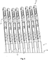
Figs. 4 and5 show a further embodiment of aribbon cable connector 1. InFig. 4 , the ribbon cable has, between theconductors 2,gaps 11 which are still closed at the connector-side end 5, in order to attain sufficient stability. Thecontact elements 21 are attached to theconductors 2 by crimping. The connections at the connector-side end 5 are then split, so that, as can be seen inFig. 5 , theindividual conductors 2 are individualised and partly insulated. As a result, they can be inserted into thecontact element receptacles 22, with thewalls 30 being situated in thegaps 11 in the mounted state. - In the embodiment according to
Figs. 4 and5 , theedge 12 of thegaps 11 is rounded particularly in a rear region, so that the risk of crack formation is smaller. -
- 1
- ribbon cable
- 2
- conductor
- 3
- insulating casing
- 5
- connector-side end
- 8
- remainder of the insulating casing
- 10
- incision
- 11
- gap
- 12
- edge
- 15
- stripped section
- 16
- section with jointly coated conductors
- 20
- ribbon cable connector
- 21
- contact element
- 22
- contact element receptacle
- 23
- shaft
- 24
- shaft wall
- 25
- depth
- 26
- plug-in depth
- 27
- contact length
- 30
- wall
- 35
- creepage distances
- 40
- plug-in aperture
- 50
- wire-side end
- 55
- insulating element
- 56
- protrusion
- 57
- protruding wall
- 100
- connector assembly
- E
- plug-in direction
- H
- vertical direction
- Q
- transverse direction
Claims (15)
- A ribbon cable connector (20) for attachment to an end (5) of a ribbon cable (1), with a plurality of contact element receptacles (22) for receiving contact elements (21), wherein two neighbouring contact element receptacles (22) are separated from one another.
- The ribbon cable connector (20) according to Claim 1, wherein the contact element receptacles (22) are separated from one another along their total extent in a plug-in direction (E), along which the contact elements (21) are plugged into the contact element receptacles (22).
- The ribbon cable connector (20) according to Claim 1 or 2, wherein the contact element receptacles (22) are separated from one another up to a plug-in aperture (40).
- The ribbon cable connector (20) according to any one of Claims 1 to 3, wherein the contact element receptacles (22) are separated from one another up to a wire-side end (50).
- The ribbon cable connector (20) according to any one of Claims 1 to 4, wherein the ribbon cable connector (20) has insulating elements (55) for separating the conductors (2) against the plug-in direction (E) beyond the contact element receptacles (22).
- The ribbon cable connector (20) according to Claim 5, wherein the insulating elements (55) are configured as protrusions (56).
- A connector assembly (100), comprising a ribbon cable connector (20) according to any one of Claims 1 to 6, and a ribbon cable (1), wherein, at a connector-side end (5) of the ribbon cable (1), the conductors (2) are individualised and, at least in sections, insulated.
- The connector assembly (100) according to Claim 7, wherein incisions (12) are present in an insulating casing (3), between the conductors (2).
- The connector assembly (100) according to Claim 7 or 8, wherein the conductors (2) are at least partly stripped at the connector-side end (5).
- The connector assembly (100) according to any one of Claims 7 to 9, wherein gaps (12) are present between the conductors (2).
- The connector assembly (100) according to Claim 10, wherein the gaps (12) are stamped.
- The connector assembly (100) according to any one of Claims 7 to 11, wherein walls (30) extend into the incisions and/or gaps.
- The connector assembly (100) according to any one of Claims 7 to 12, wherein the incisions (10) or gaps (11) have a depth (25) which corresponds to at least the difference between a plug-in depth (26) along which the conductors (2) are plugged in the ribbon cable connector (20), and a contact length (27) along which the conductors (2) are stripped.
- Use of a connector for round cables with a plurality of neighbouring, mutually separated contact element receptacles (22) for receiving contact elements (21) for contacting a ribbon cable (1).
- The use of a connector according to Claim 14, wherein the ribbon cable (1) has insulated and individualised conductors (2) at a connector-side end (5), at least over a part of its length.
Applications Claiming Priority (1)
| Application Number | Priority Date | Filing Date | Title |
|---|---|---|---|
| DE102018207794.0A DE102018207794A1 (en) | 2018-05-17 | 2018-05-17 | Ribbon cable connector, connector assembly and use of a connector |
Publications (1)
| Publication Number | Publication Date |
|---|---|
| EP3570379A1 true EP3570379A1 (en) | 2019-11-20 |
Family
ID=66529880
Family Applications (1)
| Application Number | Title | Priority Date | Filing Date |
|---|---|---|---|
| EP19174107.3A Pending EP3570379A1 (en) | 2018-05-17 | 2019-05-13 | Ribbon cable connector |
Country Status (4)
| Country | Link |
|---|---|
| US (2) | US10950963B2 (en) |
| EP (1) | EP3570379A1 (en) |
| CN (1) | CN110504569A (en) |
| DE (1) | DE102018207794A1 (en) |
Cited By (1)
| Publication number | Priority date | Publication date | Assignee | Title |
|---|---|---|---|---|
| EP4030563A1 (en) * | 2021-01-14 | 2022-07-20 | TE Connectivity Germany GmbH | Ribbon cable connector with a clamping device |
Families Citing this family (3)
| Publication number | Priority date | Publication date | Assignee | Title |
|---|---|---|---|---|
| DE102018207794A1 (en) * | 2018-05-17 | 2019-11-21 | Te Connectivity Germany Gmbh | Ribbon cable connector, connector assembly and use of a connector |
| US11069994B2 (en) * | 2019-03-25 | 2021-07-20 | Aptiv Technologies Limited | Electrical cable assembly, method and apparatus for making same and electrical terminal for same |
| JP7567828B2 (en) * | 2022-02-17 | 2024-10-16 | トヨタ自動車株式会社 | connector |
Citations (5)
| Publication number | Priority date | Publication date | Assignee | Title |
|---|---|---|---|---|
| JP2001210146A (en) * | 2000-01-26 | 2001-08-03 | Yazaki Corp | Branch terminal structure of flat circuit body |
| JP2002334617A (en) * | 2001-03-06 | 2002-11-22 | Furukawa Electric Co Ltd:The | Flat cable with connector |
| JP2003203699A (en) * | 2002-01-08 | 2003-07-18 | Auto Network Gijutsu Kenkyusho:Kk | Flexible flat cable connector connection structure |
| US20070077807A1 (en) * | 2005-10-03 | 2007-04-05 | Yazaki Corporation | Crimping apparatus for terminal |
| JP2015135754A (en) * | 2014-01-17 | 2015-07-27 | 矢崎総業株式会社 | Flat cable with connector and flat cable |
Family Cites Families (20)
| Publication number | Priority date | Publication date | Assignee | Title |
|---|---|---|---|---|
| US4561714A (en) * | 1983-12-08 | 1985-12-31 | Bally Midway Mfg. Co. | Contact assembly for ribbon cable |
| US4564253A (en) | 1984-12-11 | 1986-01-14 | Aries Electronics, Inc. | Crimp-on connector for flat cable |
| DE19927300C2 (en) | 1999-06-15 | 2002-01-31 | Tyco Electronics Logistics Ag | joint |
| FR2800520B1 (en) * | 1999-10-28 | 2001-12-14 | Fci Automotive France | IMPROVEMENT IN CONNECTION DEVICES FOR FLEXIBLE CIRCUIT |
| JP3693153B2 (en) * | 1999-11-01 | 2005-09-07 | 住友電装株式会社 | Flat conductor terminal bracket |
| JP3775557B2 (en) * | 1999-11-04 | 2006-05-17 | 住友電装株式会社 | connector |
| JP2001210410A (en) * | 2000-01-28 | 2001-08-03 | Yazaki Corp | Terminal structure of flat circuit body |
| DE20319011U1 (en) * | 2003-12-05 | 2005-04-21 | Molex Incorporated, Lisle | Flat conductor connector for sealed applications |
| US7044772B2 (en) * | 2004-06-01 | 2006-05-16 | Molex Incorporated | Electrical connector and cable assembly |
| JP4708001B2 (en) * | 2004-11-18 | 2011-06-22 | 第一電子工業株式会社 | connector |
| JP2006294386A (en) * | 2005-04-08 | 2006-10-26 | Tyco Electronics Amp Kk | Electric connector, wire harness and method for wire harness arrangement |
| JP4568210B2 (en) | 2005-11-14 | 2010-10-27 | 矢崎総業株式会社 | Terminal metal fittings and flat circuit body with terminals |
| JP4500254B2 (en) * | 2005-12-26 | 2010-07-14 | 矢崎総業株式会社 | Flat circuit body |
| CN201222540Y (en) * | 2008-02-29 | 2009-04-15 | 菲尼克斯电气公司 | Electric connection plug |
| JP5390838B2 (en) * | 2008-11-21 | 2014-01-15 | 古河電気工業株式会社 | Flat cable and flat cable connector |
| JP5403801B2 (en) * | 2009-07-02 | 2014-01-29 | 矢崎総業株式会社 | Flexible flat cable connection structure and connection method |
| JP2013038039A (en) | 2011-08-11 | 2013-02-21 | Yazaki Corp | Water proof connector for flat cable and manufacturing method of the same |
| JP6319636B2 (en) | 2015-01-29 | 2018-05-09 | 株式会社オートネットワーク技術研究所 | Communication connector |
| DE102018207794A1 (en) * | 2018-05-17 | 2019-11-21 | Te Connectivity Germany Gmbh | Ribbon cable connector, connector assembly and use of a connector |
| US10431906B1 (en) * | 2018-07-12 | 2019-10-01 | Ford Global Technologies, Llc | Automotive wiring harness flat cable end termination |
-
2018
- 2018-05-17 DE DE102018207794.0A patent/DE102018207794A1/en active Pending
-
2019
- 2019-05-13 EP EP19174107.3A patent/EP3570379A1/en active Pending
- 2019-05-16 CN CN201910405309.1A patent/CN110504569A/en active Pending
- 2019-05-17 US US16/415,188 patent/US10950963B2/en active Active
-
2020
- 2020-11-23 US US17/101,777 patent/US11545774B2/en active Active
Patent Citations (5)
| Publication number | Priority date | Publication date | Assignee | Title |
|---|---|---|---|---|
| JP2001210146A (en) * | 2000-01-26 | 2001-08-03 | Yazaki Corp | Branch terminal structure of flat circuit body |
| JP2002334617A (en) * | 2001-03-06 | 2002-11-22 | Furukawa Electric Co Ltd:The | Flat cable with connector |
| JP2003203699A (en) * | 2002-01-08 | 2003-07-18 | Auto Network Gijutsu Kenkyusho:Kk | Flexible flat cable connector connection structure |
| US20070077807A1 (en) * | 2005-10-03 | 2007-04-05 | Yazaki Corporation | Crimping apparatus for terminal |
| JP2015135754A (en) * | 2014-01-17 | 2015-07-27 | 矢崎総業株式会社 | Flat cable with connector and flat cable |
Cited By (2)
| Publication number | Priority date | Publication date | Assignee | Title |
|---|---|---|---|---|
| EP4030563A1 (en) * | 2021-01-14 | 2022-07-20 | TE Connectivity Germany GmbH | Ribbon cable connector with a clamping device |
| US11936129B2 (en) | 2021-01-14 | 2024-03-19 | Te Connectivity Germany Gmbh | Ribbon cable connector with a clamping device |
Also Published As
| Publication number | Publication date |
|---|---|
| US20210075136A1 (en) | 2021-03-11 |
| DE102018207794A1 (en) | 2019-11-21 |
| CN110504569A (en) | 2019-11-26 |
| US20190356072A1 (en) | 2019-11-21 |
| US10950963B2 (en) | 2021-03-16 |
| US11545774B2 (en) | 2023-01-03 |
Similar Documents
| Publication | Publication Date | Title |
|---|---|---|
| JP6950064B2 (en) | Terminals and their electrical connectors | |
| US11545774B2 (en) | Ribbon cable connector, connector assembly and use of a connector | |
| US9698548B2 (en) | Electrical busway splice connector | |
| CN105594069B (en) | Connector | |
| US8753141B2 (en) | Adapter for connecting a harness to magnet wires | |
| CN103814479B (en) | Constrained Large Deflection Insulation Displacement Terminals and Connectors | |
| TW201830803A (en) | A plug assembly and a method for assembling a plug connector | |
| US7901254B2 (en) | Connector block | |
| CN104124574A (en) | Electrical cable connector shield with positive retention locking feature | |
| US9583885B2 (en) | Connector assembly with grounding spring | |
| JP2014060144A (en) | High speed electric contact assembly | |
| CN104348029A (en) | Insulation displacement connector | |
| KR20110089275A (en) | Plug connector for star quad cable | |
| US4561712A (en) | Versatile electric connector | |
| US10770846B2 (en) | Electric connector with wire holder | |
| CN102985991A (en) | Socket connector | |
| US20150349476A1 (en) | Multiport terminal with current bars | |
| EP4170825A1 (en) | Linearized magnet wire connector | |
| US8933337B2 (en) | Device for preventing the establishment of an electric arc between two conductive elements | |
| WO2024246598A1 (en) | Fitting element for connectors | |
| US10700452B2 (en) | Connector terminal | |
| JP2704486B2 (en) | Electrical connector assembly | |
| EP1020962A1 (en) | Electrical connector assembly having a grounding clip | |
| EP2705577B1 (en) | High-voltage resistance of a connector interface | |
| US8297995B2 (en) | Device for preventing the establishment of an electric arc between two conductive elements |
Legal Events
| Date | Code | Title | Description |
|---|---|---|---|
| PUAI | Public reference made under article 153(3) epc to a published international application that has entered the european phase |
Free format text: ORIGINAL CODE: 0009012 |
|
| STAA | Information on the status of an ep patent application or granted ep patent |
Free format text: STATUS: THE APPLICATION HAS BEEN PUBLISHED |
|
| AK | Designated contracting states |
Kind code of ref document: A1 Designated state(s): AL AT BE BG CH CY CZ DE DK EE ES FI FR GB GR HR HU IE IS IT LI LT LU LV MC MK MT NL NO PL PT RO RS SE SI SK SM TR |
|
| AX | Request for extension of the european patent |
Extension state: BA ME |
|
| STAA | Information on the status of an ep patent application or granted ep patent |
Free format text: STATUS: REQUEST FOR EXAMINATION WAS MADE |
|
| 17P | Request for examination filed |
Effective date: 20200325 |
|
| RBV | Designated contracting states (corrected) |
Designated state(s): AL AT BE BG CH CY CZ DE DK EE ES FI FR GB GR HR HU IE IS IT LI LT LU LV MC MK MT NL NO PL PT RO RS SE SI SK SM TR |
|
| STAA | Information on the status of an ep patent application or granted ep patent |
Free format text: STATUS: EXAMINATION IS IN PROGRESS |
|
| 17Q | First examination report despatched |
Effective date: 20201221 |