EP3570258A1 - Electronic device arrangement, method for operating an electronic device arrangement, security device, and automated teller machine - Google Patents
Electronic device arrangement, method for operating an electronic device arrangement, security device, and automated teller machine Download PDFInfo
- Publication number
- EP3570258A1 EP3570258A1 EP18172612.6A EP18172612A EP3570258A1 EP 3570258 A1 EP3570258 A1 EP 3570258A1 EP 18172612 A EP18172612 A EP 18172612A EP 3570258 A1 EP3570258 A1 EP 3570258A1
- Authority
- EP
- European Patent Office
- Prior art keywords
- terminals
- electronic device
- universal
- serial
- security device
- Prior art date
- Legal status (The legal status is an assumption and is not a legal conclusion. Google has not performed a legal analysis and makes no representation as to the accuracy of the status listed.)
- Granted
Links
Images



Classifications
-
- G—PHYSICS
- G06—COMPUTING OR CALCULATING; COUNTING
- G06F—ELECTRIC DIGITAL DATA PROCESSING
- G06F21/00—Security arrangements for protecting computers, components thereof, programs or data against unauthorised activity
- G06F21/70—Protecting specific internal or peripheral components, in which the protection of a component leads to protection of the entire computer
- G06F21/82—Protecting input, output or interconnection devices
- G06F21/85—Protecting input, output or interconnection devices interconnection devices, e.g. bus-connected or in-line devices
-
- G—PHYSICS
- G07—CHECKING-DEVICES
- G07F—COIN-FREED OR LIKE APPARATUS
- G07F19/00—Complete banking systems; Coded card-freed arrangements adapted for dispensing or receiving monies or the like and posting such transactions to existing accounts, e.g. automatic teller machines
- G07F19/20—Automatic teller machines [ATMs]
- G07F19/205—Housing aspects of ATMs
-
- G—PHYSICS
- G07—CHECKING-DEVICES
- G07C—TIME OR ATTENDANCE REGISTERS; REGISTERING OR INDICATING THE WORKING OF MACHINES; GENERATING RANDOM NUMBERS; VOTING OR LOTTERY APPARATUS; ARRANGEMENTS, SYSTEMS OR APPARATUS FOR CHECKING NOT PROVIDED FOR ELSEWHERE
- G07C9/00—Individual registration on entry or exit
- G07C9/00174—Electronically operated locks; Circuits therefor; Nonmechanical keys therefor, e.g. passive or active electrical keys or other data carriers without mechanical keys
- G07C9/00896—Electronically operated locks; Circuits therefor; Nonmechanical keys therefor, e.g. passive or active electrical keys or other data carriers without mechanical keys specially adapted for particular uses
- G07C9/00912—Electronically operated locks; Circuits therefor; Nonmechanical keys therefor, e.g. passive or active electrical keys or other data carriers without mechanical keys specially adapted for particular uses for safes, strong-rooms, vaults or the like
-
- G—PHYSICS
- G07—CHECKING-DEVICES
- G07C—TIME OR ATTENDANCE REGISTERS; REGISTERING OR INDICATING THE WORKING OF MACHINES; GENERATING RANDOM NUMBERS; VOTING OR LOTTERY APPARATUS; ARRANGEMENTS, SYSTEMS OR APPARATUS FOR CHECKING NOT PROVIDED FOR ELSEWHERE
- G07C9/00—Individual registration on entry or exit
- G07C9/00174—Electronically operated locks; Circuits therefor; Nonmechanical keys therefor, e.g. passive or active electrical keys or other data carriers without mechanical keys
- G07C9/00944—Details of construction or manufacture
-
- G—PHYSICS
- G07—CHECKING-DEVICES
- G07F—COIN-FREED OR LIKE APPARATUS
- G07F19/00—Complete banking systems; Coded card-freed arrangements adapted for dispensing or receiving monies or the like and posting such transactions to existing accounts, e.g. automatic teller machines
- G07F19/20—Automatic teller machines [ATMs]
- G07F19/201—Accessories of ATMs
-
- G—PHYSICS
- G07—CHECKING-DEVICES
- G07F—COIN-FREED OR LIKE APPARATUS
- G07F19/00—Complete banking systems; Coded card-freed arrangements adapted for dispensing or receiving monies or the like and posting such transactions to existing accounts, e.g. automatic teller machines
- G07F19/20—Automatic teller machines [ATMs]
- G07F19/207—Surveillance aspects at ATMs
-
- G—PHYSICS
- G07—CHECKING-DEVICES
- G07F—COIN-FREED OR LIKE APPARATUS
- G07F19/00—Complete banking systems; Coded card-freed arrangements adapted for dispensing or receiving monies or the like and posting such transactions to existing accounts, e.g. automatic teller machines
- G07F19/20—Automatic teller machines [ATMs]
- G07F19/209—Monitoring, auditing or diagnose of functioning of ATMs
-
- G—PHYSICS
- G07—CHECKING-DEVICES
- G07C—TIME OR ATTENDANCE REGISTERS; REGISTERING OR INDICATING THE WORKING OF MACHINES; GENERATING RANDOM NUMBERS; VOTING OR LOTTERY APPARATUS; ARRANGEMENTS, SYSTEMS OR APPARATUS FOR CHECKING NOT PROVIDED FOR ELSEWHERE
- G07C9/00—Individual registration on entry or exit
- G07C9/00174—Electronically operated locks; Circuits therefor; Nonmechanical keys therefor, e.g. passive or active electrical keys or other data carriers without mechanical keys
- G07C9/00944—Details of construction or manufacture
- G07C2009/00952—Electronic keys comprising a mechanical key within their housing, e.g. extractable or retractable emergency key
Definitions
- Various embodiments relate generally to an electronic device arrangement, a method for operating an electronic device arrangement, a security device, and an automated teller machine including a security device.
- an automated teller machine or any other device may be prone to physical attacks and/or electronic attacks.
- one or more objects e.g. money, gold, or other things of value
- an electromechanical device may be operated inside the safe unit that allows transferring at least one of the objects out of the safe unit.
- This electromechanical device may directly or indirectly communicate with a computing device or any other electronic device outside the safe unit.
- the computing device may be disposed in a head unit of the ATM.
- a communication interface may be implemented.
- Various embodiments are related to an electronic device arrangement including: a first electronic device; a second electronic device; and a Universal-Serial-Bus (USB) interface communicatively coupling the first electronic device and the second electronic device with one another, wherein the Universal-Serial-Bus interface includes an electrical connection structure to electrically connect the first electronic device and the second electronic device with one another and a switch to disconnect the electrical connection structure; a measurement circuit to measure one or more electrical properties associated with the electrical connection structure and/or the first electronic device; and one or more processors configured to control the switch based on the measured one or more electrical properties.
- USB Universal-Serial-Bus
- the security device may include: a first set of terminals to connect the security device with a Universal-Serial-Bus connector, a second set of terminals to connect the security device with an electronic device, a controllable terminal connection structure to connect the first set of terminals and the second set of terminals with one another and to disconnect the first set of terminals and the second set of terminals from one another to control a physical connection of the Universal-Serial-Bus connector to the electronic device; a measurement circuit coupled to the first set of terminals to measure one or more electrical properties associated with the Universal-Serial-Bus connector when connected to the first set of terminals; and one or more processors configured to control the controllable terminal connection structure based on the determined one or more electrical properties.
- Various embodiments are related to an automated teller machine (ATM) including a security device to monitor and control a Universal-Serial-Bus interface.
- ATM automated teller machine
- Coupled is used herein to mean any suitable type of connection, which may include a direct connection or an indirect connection.
- electrically connected that is used herein to describe an electrical connection between terminals, pins, etc., may be understood as an electrically conductive connection with, for example, ohmic behavior.
- An electrical connection may be provided by one or more metal wires, one or more metal pins, etc.
- the metal may be or may include, for example, copper, aluminum, silver, gold, etc.
- control data or “measurement data” may be understood to include information in any suitable analog or digital form.
- the one or more processors described herein may be configured as or part of a controller or of more than one controllers.
- processor or “controller” as, for example, used herein may be understood as any kind of entity that allows processing data.
- the data may be processed in accordance with one or more specific functions executed by the processor or controller.
- a processor or controller as used herein may be understood as any kind of circuit, e.g., any kind of analog or digital circuit.
- processing as for example used herein referring to data processing may be understood as any kind of operation, e.g., an I/O operation, and/or any kind of logic operation.
- An I/O operation may include, for example, storing and reading from a memory.
- one or more memories may be associated with the one or more processors described herein.
- memory as referred to herein may be understood as a non-transitory computer-readable medium in which data or information can be stored for retrieval.
- system e.g., a computing system, etc.
- elements can be, by way of example and not of limitation, one or more mechanical components, one or more electrical components, one or more instructions (e.g., encoded in storage media), and/or one or more processors, and the like.
- USB Universal-Serial-Bus
- a connection of a host (also referred to as master) device e.g. any suitable type of computing device
- client also referred to as slave
- I/O devices I/O devices, sensors, controllers, etc.
- the versions of the USB standard include USB 1.0 released in January 1996; USB 1.1 released in August 1998; USB 2.0 released in April 2000, USB 3.0 released in November 2008, USB 3.1 released in July 2013, USB 3.2 released in September 2017. Further, USB Battery Charging and USB Power Delivery standards are associated with the USB standard.
- USB connectors may include male connectors (also referred to as plugs) and female connectors (also referred to as receptacles or ports).
- the connectors may be of various types, wherein a male and a female connector of the same type may fit together.
- the types may include: Type-A; Type-A Super Speed; Type-B; Type-B Super Speed; Type-C; Mini-A; Mini-B; Micro-A; Micro-B; Micro-B Super Speed.
- Some female connectors e.g. Mini-AB, Micro-AB
- the Super Speed connectors may fit to the standard connectors associated therewith.
- various types of USB cables may be provided.
- the connectors of Type-A and Type-B have four pins and the corresponding cables have four cores. Illustratively four single wires may be used to provide one four-core cable.
- the connectors of Mini/Micro-A and Mini/Micro-B type have five pins and the corresponding cables have five cores.
- the connectors of Type-A Super Speed and Type-B Super Speed have nine pins and the corresponding cables have nine cores.
- the connectors of Mini/Micro-A Super Speed and Mini/Micro-B Super Speed type have ten pins and the corresponding cables have ten cores.
- the connectors of Type-C have 24 pins (arranged in a twofold rotational symmetry) and the corresponding cables have 24 cores.
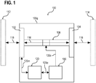
- FIG. 1 illustrates a security device 100 in a schematic view, according to various embodiments.
- the security device 100 may include a first set of terminals 102 and a second set of terminals 104.
- the first set of terminals 102 may be configured to connect the security device 100 with a USB connector 112.
- the second set of terminals 104 may be configured to connect the security device 100 with an electronic device 114 (also referred to as second electronic device).
- the security device 100 i.e. at least the respective terminals 102, 104 of the security device 100, may be part of a USB interface that allows a communication of the electronic device 114 with another electronic device via the USB connector 112.
- the USB connector 112 may be a USB plug that may be plugged into a USB port of a computing device. Alternatively, the USB connector 112 may be USB port to host any suitable type of USB device.
- the security device 100 may further include a controllable terminal connection structure 106.
- the controllable terminal connection structure 106 may be configured, selectively, to either connect the first set of terminals 102 or the second set of terminals 104 with one another and to disconnect the first set of terminals 102 and the second set of terminals 104 from one another.
- the controllable terminal connection structure 106 may be configured to control a physical connection 116 (e.g. an electrically conductive connection) of the USB connector 112 to the electronic device 114.
- controllable terminal connection structure 106 may be configured either to connect the first set of terminals 102 and the second set of terminals 104 with one another (and therefore to allow a communication with the electronic device 114 via the USB connector 112) or to disconnect the first set of terminals 102 and the second set of terminals 104 from one another (and therefore to prevent a communication with the electronic device 114 via the USB connector 112) in a controlled manner.
- the security device 100 may include a measurement circuit 120 to measure 120m one or more electrical properties 120e associated with the USB connector 112.
- the measurement circuit 120 may be used to check whether the USB connector 112 and/or an additional electronic device (e.g. a computing device) that is connect to the USB connector 112 may be manipulated.
- the one or more electrical properties 120e measured via the measurement circuit 120 may be within one or more predefined reference ranges associated with the one or more electrical properties 120e. However, in the case that the USB connector 112 is manipulated, e.g. in the case of an attack, the one or more electrical properties 120e measured via the measurement circuit 120 may be outside the one or more predefined reference ranges.
- the USB connector 112 may be part of a computing device or may be coupled with a computing device.
- the one or more electrical properties 120e measured via the measurement circuit 120 may be within one or more predefined reference ranges accordingly.
- the predefined reference ranges may include one or more thresholds (e.g. lower and/or upper limits) associated with the respective values of the one or more electrical properties 120e.
- the one or more electrical properties 120e measured via the measurement circuit 120 may be outside the one or more predefined reference ranges.
- the security device 100 may include one or more processors 130 configured to control 130c the controllable terminal connection structure 106 based on the determined one or more electrical properties 120e.
- the one or more processors 130 may at least receive measurement data from the measurement circuit 120.
- the one or more processors 130 may be configured to trigger and/or control the measurement circuit 120.
- the measurements 120m may be performed continuously or in predefined time intervals.
- the one or more processors 130 may be configured to disconnect the first set of terminals 102 from the second set of terminals 104 in the case of an attack related to the USB connector 112.
- An attack may be detected based one the measurements 120m carried out via the measurement circuit 120, e.g. an attack may be detected if the one or more electrical properties 120e measured via the measurement circuit 120 are outside the one or more predefined reference ranges.
- a predefined electrical resistance may be associated with a non-manipulated USB connector 112. When the actual electrical resistance measured via the measurement circuit 120 differs from the predefined electrical resistance, an attack may be likely and the one or more processors 130 may physically disconnect the connection 116 between the USB connector 112 and the electronic device 114.
- a control signal 130c may be provided from the one or more processors 130 to the controllable terminal connection structure 106, e.g. to a switch off the controllable terminal connection structure 106.
- the security device 100 may include a housing 100g that surrounds the controllable terminal connection structure 106, the measurement circuit 120, the one or more processors 130, etc.
- the first set of terminals 102 and the second set of terminals 104 may be exposed to connect the USB connector 112 and the electronic device 114 accordingly.
- FIG. 2 illustrates a part lOOp of a security device 100 in a schematic view, according to various embodiments.
- the security device 100 illustrated in FIG. 1 may include the same of similar features as described with respect to the part lOOp of the security device 100 illustrated in FIG. 2 .
- the controllable terminal connection structure 106 may include a switch 206 (e.g. an electrical switch, an electrical relay, etc.) that may be used to disconnect an electrically conductive connection 116 between the first set of terminals 102 and the second set of terminals 104.
- the switch 206 may be used to disconnect the physical connection 116 between the USB connector 112 and the electronic device 114 or in other words to disconnect the USB interface.
- the communication from and to the electronic device 114 may be prevented in the case of an attack, e.g. an attack carried out via the USB connector 112.
- the switch 206 may have at least a first switching state 206a and a second switching state 206b.
- the first switching state 206a the first set of terminals 102 and the second set of terminals 104 are connected with one another.
- a first terminal of the first set of terminals 102, a second terminal of the first set of terminals 102, a third terminal of the first set of terminals 102, and a fourth terminal of the first set of terminals 102 are connected to a first terminal of the second set of terminals 104, a second terminal of the second set of terminals 104, a third terminal of the second set of terminals 104, and a fourth terminal of the second set of terminals 104 respectively.
- the first set of terminals 102 and the second set of terminals 104 are disconnected from one another.
- at least one of the terminals of the first set of terminals 102 is not connected to the corresponding terminal of the second set of terminals 104.
- the one or more processors 130 may be configured to control the controllable terminal connection structure 106 only by switching the switch 206 from the first switching state 206a into the second switching state 206b. In other words, after switching the switch 206 from the first switching state 206a into the second switching state 206b, e.g. in the case of an attack, the switch 206 may not be switched back into the first switching state 206a via the one or more processors 130.
- switch 206 can be manipulated as well to maintain the connection 116 between the first set of terminals 102 and the second set of terminals 104 or to reconnect the first set of terminals 1 02 and the second set of terminals 104 despite an attack was detected and the connection 116 should be disconnected.
- the switch 206 may be reset (e.g. switched back into the first switching state 206a) manually, e.g. via an authorized person that has physical access to the switch 206 or to a mechanism and/or circuit for resetting the switch 206.
- the controllable terminal connection structure 106 may further include a mechanical mechanism 216 for switching the switch 206 from the second switching state 206b into the first switching state 206a.
- a lockable mechanical protection structure 226 may be used to restrict a physical access 226a to the mechanical mechanism 216 to authorized persons only.
- the controllable terminal connection structure 106 may further include an additional controller (independent from the one or more processors 130) for switching the switch 206 from the second switching state 206b into the first switching state 206a.
- the switch 206 may be reset (e.g. switched back into the first switching state 206a) manually, via an authorized person that has physical access to the switch 206 or to the additional controller for resetting the switch 206.
- the additional controller may be configured to require a manual input at a user interface to reset the switch.
- a lockable mechanical protection structure 226 may be used to restrict a physical access 226a to the user interface to authorized persons only.
- FIG. 3 illustrates a security device 100 in a schematic view, according to various embodiments.
- the security device 100 illustrated in FIG. 1 may include the same of similar features as described with reference to the security device 100 illustrated in FIG. 3 .
- the first set of terminals 102 and the second set of terminals 104 may each include at least four terminals 102t, 104t associated with at least four cores of a USB cable and/or at least four USB pins of the USB connector 112.
- the first set of terminals 102 and the second set of terminals 104 may each include five terminals 102t, nine terminals 102t, ten terminals 102t, or at least twenty-four terminals 102t depending on the type of USB interface.
- the first set of terminals 102 may include at least two additional terminals 102s associated with at least two additional cores of the USB cable and/or at least two additional pins of the USB connector 112, see for example FIG. 7 .
- the at least four terminals 102t of the first set of terminals 102 may be used for measuring 120m the one or more electrical properties 120e via the measurement circuit 120.
- the at least two additional terminals 102s of the first set of terminals 102 may be used for measuring 120m the one or more electrical properties 120e via the measurement circuit 120.
- the one or more electrical properties 120e may include an electrical resistance and/or an electrical impedance of any device, cable, connector, etc. that is/are connected to the first set of terminals 102.
- the reference data associated with the one or more electrical properties 120e may be measured. The reference data representing a non-manipulated state of the device, cable, connector, etc. that is/are connected to the first set of terminals 102.
- the security device 100 may further include at least one power supply (e.g. a battery) 310 to supply the one or more processors 130 and/or the measurement circuit 120.
- the one or more processors 130 and/or the measurement circuit 120 may be supplied via an internal power supply 310.
- the security device 100 may be configured as a stand-alone device disposed within a safe unit. This implements for example an additional security aspect, since it may be avoided that the security device 100 can be disabled by an unauthorized person, e.g. by manipulating a power supply.
- the power supply 310 may be disposed inside the housing 100g of the security device 100.
- the housing 100g of the security device 100 may be configured as a safe.
- the housing 100g of the security device 100 may be disposed in a safe.
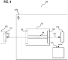
- FIG. 4 illustrates an automated teller machine (ATM) 400 in a schematic view, according to various embodiments.
- the ATM 400 may include the security device 100 described herein to secure a USB interface of the ATM 400.
- any other communication interface may be protected in a similar way.
- the ATM 400 may include a safe unit 400s.
- the interior of the safe unit 400s may be only accessible for authorized persons.
- the safe unit 400s may include a mechanical protection structure to restrict a physical access to the interior of the safe unit 400s and at least one door to access the interior of the safe unit 400s.
- the door may be protected via a locking mechanism or any other suitable structure.
- the security device 100 may be disposed inside the safe unit 400s.
- the security device 100 may be configured to operate (e.g. to measure the one or more electronic properties 120e associated with the first set of terminals 102 and/or the USB connector 112 and the control of the controllable terminal connection structure 106) independently from any computing system outside the safe unit 400s.
- the ATM 400 may include a USB connector 112 disposed outside the safe unit 400s and connected to the first set of terminals 102 of the security device 100. Further, the ATM may include an electronic device 114 disposed inside the safe unit 400s and connected to the second set of terminals 104 of the security device 100.
- the ATM 400 may further include a computing system 422 disposed outside the safe unit 400s.
- the USB connector 112 may be connected to the computing system 422 or may be part of the computing system 422.
- the computing system 422 and the electronic device 114 may be configured to communicate with one another via the USB interface, wherein the security device 100 may be configured to monitor the USB interface to determine a manipulation (e.g. in the case of an attack) of the part of the USB interface disposed outside the safety unit 400s or of the computing system 422.
- the computing system 422 may be disposed in a head unit of the ATM 400.
- the ATM 400 may further include an electromechanical device 424 disposed inside the safe unit 400s.
- the electronic device 114 may be configured to control an operation of the electromechanical device 424 based on control data transmitted via the USB connector 112.
- the computing system 422 may be configured to provide control data associated with an operation of the electromechanical device 424 and to provide the control data via the USB interface to the electronic device 114 that controls the electromechanical device 424 based on the control data.
- the electronic device 114 may be part of the electromechanical device 424 and the computing system 422 may be configured to control the electromechanical device 424.
- FIG. 5 illustrates an electronic device arrangement 500 in a schematic view, according to various embodiments.
- the electronic device arrangement 500 may include a first electronic device 502 and a second electronic device 504.
- a USB interface 510 may be used to communicatively couple the first electronic device 502 and the second electronic device 504 with one another.
- the USB interface 510 may include an electrical connection structure 516 to electrically conductively connect the first electronic device 502 and the second electronic device 504 with one another.
- the USB interface 510 may further include a switch 506 to disconnect the electrical connection structure 516, e.g. in a controlled manner.
- the electronic device arrangement 500 may include a measurement circuit 520 to measure 520m one or more electrical properties 520e associated with the electrical connection structure 516 and/or the first electronic device 502. Further, the electronic device arrangement 500 may include one or more processors 530 configured to control 530c the switch 506 based on the measured one or more electrical properties 520e. As an example, the one or more processors 530 may be configured to trigger the switch 506 to disconnect the electrical connection structure 516 based on the measured one or more electrical properties 520e.
- the electrical connection structure 516 may be controlled via a security device 100 or a similar device as described herein.
- the electronic device arrangement 500 may be an ATM
- the first electronic device 502 may be a computing device disposed in a head unit of the ATM and including at least one USB connector.
- the second electronic device 504 may be an electromechanical tower (e.g. including the electronic device 114 and the electromechanical device 424) disposed in a safe unit of the ATM.
- the USB interface 510 that provides the communication between the two electronic devices 502, 504 may be monitored via the security device 100 to determine an attack to the second electronic device 504 via the USB interface 510 and/or the first electronic device 502, as described herein.
- An attack to the second electronic device 504 may include a manipulation of a USB cable, a USB connector, etc.
- An attack to the second electronic device 504 may further include a manipulation (e.g. a replacement, etc.) of the first electronic device 502.
- the one or more electrical properties 520e may include an electrical resistance and/or an electrical impedance associated with at least a part of the electrical connection structure 516. Additionally or alternatively, the one or more electrical properties 520e may include an electrical resistance and/or an electrical impedance associated with at least a part of the first electronic device 502.
- FIG. 6 illustrates a schematic flow diagram of a method 600 for operating an electronic device arrangement 500, according to various embodiments.
- the method 600 may include: in 610, communicatively coupling a first electronic device 502 of the electronic device arrangement 500 to a second electronic device 504 of the electronic device arrangement 500 via a USB interface 510, wherein the USB interface 510 includes an electrical connection structure 516 to electrically connect the first electronic device 502 and the second electronic device 504 with one another and a switch 506 to disconnect the electrical connection structure 516; in 620, measuring one or more electrical properties 520e associated with the electrical connection structure 516 and/or with the first electronic device 502; and, in 630, triggering the switch 506 to disconnect the electrical connection structure 516 based on the measured one or more electrical properties 520e.
- the switch 506 may be triggered when the measured one or more electrical properties 520e exceed or fall below one or more pre-defined thresholds.
- the method 600 may further include, e.g. after triggering the switch 506, manually resetting the switch 506 via a mechanical mechanism to electrically connect the first electronic device 502 and the second electronic device 504 with one another.
- the mechanical mechanism may be configured as described herein with reference to the mechanical mechanism 216 of the security device 100.
- the method 600 may further include, e.g. before manually resetting the switch 506, unlocking a mechanical protection structure to physically access the mechanical mechanism.
- the mechanical protection structure may be configured as described herein with reference to the lockable mechanical protection structure 226 of the security device 100 and/or the safe unit 400s of the ATM 400.
- the safe unit may be the lockable mechanical protection structure 226.
- FIG. 7 illustrates a USB connector arrangement 712 in a schematic view, according to various embodiments.
- the USB connector arrangement 712 may include a USB port 712f and a USB plug 712m plugged into the USB port 712f.
- the USB plug 712m may be the USB connector 112 of the security device 100 described herein.
- the USB plug 712m may be connected with a computing device 422, e.g. with a USB port of the computing device 422, as described herein.
- the USB port 712f may be the USB connector 112 of the security device 100 described herein.
- any suitable electronic device including a USB plug 712m may be connected with the USB port 712f.
- the USB connector e.g. the USB plug 712m
- the USB connector may include at least four pins 702 and at least two additional pins 702s.
- the additional pins 702s may be used to measure the one or more electrical properties via the measurement circuit, e.g. when the USB connector is connected to the first terminal 102 of the security device 100, accordingly.
- the additional pins 702s may be used to identify and/or to authenticate any electronic device coupled to the USB connector.
- a predefined electronic device to be connected to the USB connector may include, for example, a pre-defined electrical resistance.
- the measurement circuit may be used to measure the actual electrical resistance of an electronic device connected to the USB connector and the one or more processors may be configured to compare the measured the actual electrical resistance of the electronic device connected to the USB connector with the pre-defined electrical resistance to determine whether the predefined electronic device is connected to the USB connector or another (e.g. manipulated) device.
- the one or more processors may be configured to disable the USB interface.
- a predefined USB connector to be connected to the first set of terminals 102 of the security device 100 may include, for example, a pre-defined electrical resistance.
- the measurement circuit may be used to measure the actual electrical resistance of an USB connector that is connected to the first set of terminals 102 of the security device 100 and the one or more processors may be configured to compare the measured the actual electrical resistance of the USB connector with the pre-defined electrical resistance to determine whether the predefined USB connector is connected to the first set of terminals 102 of the security device 100 or another (e.g. manipulated) structure.
- the one or more processors may be configured to disable the USB interface.
- the USB connector 712f, 712m may include additional pins 702s and a predefined electrical resistor electrically connecting the additional pins 702s with one another.
Landscapes
- Physics & Mathematics (AREA)
- General Physics & Mathematics (AREA)
- Business, Economics & Management (AREA)
- Accounting & Taxation (AREA)
- Finance (AREA)
- Engineering & Computer Science (AREA)
- Computer Hardware Design (AREA)
- Theoretical Computer Science (AREA)
- Manufacturing & Machinery (AREA)
- Computer Security & Cryptography (AREA)
- Software Systems (AREA)
- General Engineering & Computer Science (AREA)
- Details Of Connecting Devices For Male And Female Coupling (AREA)
- Power Sources (AREA)
Abstract
Description
- Various embodiments relate generally to an electronic device arrangement, a method for operating an electronic device arrangement, a security device, and an automated teller machine including a security device.
- In general, an automated teller machine (ATM) or any other device may be prone to physical attacks and/or electronic attacks. As an example, one or more objects (e.g. money, gold, or other things of value) may be protected from unauthorized physical access via a safe unit or any other suitable mechanical protection structure of the ATM. However, to provide authorized access to the one or more objects disposed within the safe unit, e.g. for a user of the ATM, an electromechanical device may be operated inside the safe unit that allows transferring at least one of the objects out of the safe unit. This electromechanical device may directly or indirectly communicate with a computing device or any other electronic device outside the safe unit. As an example, the computing device may be disposed in a head unit of the ATM. For the communication between a first electronic device outside the safe unit (e.g. the computing device) and a second electronic device inside the safe unit (e.g. the electromechanical device) a communication interface may be implemented.
- Various embodiments are related to an electronic device arrangement including: a first electronic device; a second electronic device; and a Universal-Serial-Bus (USB) interface communicatively coupling the first electronic device and the second electronic device with one another, wherein the Universal-Serial-Bus interface includes an electrical connection structure to electrically connect the first electronic device and the second electronic device with one another and a switch to disconnect the electrical connection structure; a measurement circuit to measure one or more electrical properties associated with the electrical connection structure and/or the first electronic device; and one or more processors configured to control the switch based on the measured one or more electrical properties.
- Various embodiments are related to a security device, e.g. for use in an electronic device arrangement, the security device may include: a first set of terminals to connect the security device with a Universal-Serial-Bus connector, a second set of terminals to connect the security device with an electronic device, a controllable terminal connection structure to connect the first set of terminals and the second set of terminals with one another and to disconnect the first set of terminals and the second set of terminals from one another to control a physical connection of the Universal-Serial-Bus connector to the electronic device; a measurement circuit coupled to the first set of terminals to measure one or more electrical properties associated with the Universal-Serial-Bus connector when connected to the first set of terminals; and one or more processors configured to control the controllable terminal connection structure based on the determined one or more electrical properties.
- Various embodiments are related to an automated teller machine (ATM) including a security device to monitor and control a Universal-Serial-Bus interface.
- In the drawings, like reference characters generally refer to the same parts throughout the different views. The drawings are not necessarily to scale, emphasis instead generally being placed upon illustrating the principles of the invention. In the following description, various embodiments of the invention are described with reference to the following drawings, in which:
-
FIG. 1 shows a security device in a schematic view, according to various embodiments; -
FIG. 2 shows a part of a security device in a schematic view, according to various embodiments; -
FIG. 3 shows a security device in a schematic view, according to various embodiments; -
FIG. 4 shows an automated teller machine in a schematic view, according to various embodiments; -
FIG. 5 shows an electronic device arrangement in a schematic view, according to various embodiments; -
FIG. 6 shows a schematic flow diagram of a method for operating an electronic device arrangement, according to various embodiments; and -
FIG. 7 shows a Universal-Serial-Bus connector arrangement in a schematic view, according to various embodiments. - The following detailed description refers to the accompanying drawings that show, by way of illustration, specific details and embodiments in which the invention may be practiced. These embodiments are described in sufficient detail to enable those skilled in the art to practice the invention. Other embodiments may be utilized and structural, logical, and electrical changes may be made without departing from the scope of the invention. The various embodiments are not necessarily mutually exclusive, as some embodiments can be combined with one or more other embodiments to form new embodiments. Various embodiments are described in connection with methods and various embodiments are described in connection with devices. However, it may be understood that embodiments described in connection with methods may similarly apply to the devices, and vice versa.
- The terms "at least one" and "one or more" may be understood to include any integer number greater than or equal to one, i.e. one, two, three, four, [...], etc. The term "a plurality" may be understood to include any integer number greater than or equal to two, i.e. two, three, four, five, [...], etc.
- The term "coupled" is used herein to mean any suitable type of connection, which may include a direct connection or an indirect connection. The term "electrically connected" that is used herein to describe an electrical connection between terminals, pins, etc., may be understood as an electrically conductive connection with, for example, ohmic behavior. An electrical connection may be provided by one or more metal wires, one or more metal pins, etc. The metal may be or may include, for example, copper, aluminum, silver, gold, etc.
- The term "data" as used herein with reference to "control data" or "measurement data" may be understood to include information in any suitable analog or digital form. The one or more processors described herein may be configured as or part of a controller or of more than one controllers.
- The terms "processor" or "controller" as, for example, used herein may be understood as any kind of entity that allows processing data. The data may be processed in accordance with one or more specific functions executed by the processor or controller. Further, a processor or controller as used herein may be understood as any kind of circuit, e.g., any kind of analog or digital circuit. The term "processing" as for example used herein referring to data processing may be understood as any kind of operation, e.g., an I/O operation, and/or any kind of logic operation. An I/O operation may include, for example, storing and reading from a memory. In other words, one or more memories may be associated with the one or more processors described herein. The term "memory" as referred to herein may be understood as a non-transitory computer-readable medium in which data or information can be stored for retrieval.
- The term "system" (e.g., a computing system, etc.) as described herein may be understood as a set of interacting elements, wherein the elements can be, by way of example and not of limitation, one or more mechanical components, one or more electrical components, one or more instructions (e.g., encoded in storage media), and/or one or more processors, and the like.
- Various embodiments are related to a Universal-Serial-Bus (USB) interface that allows a communication between at least two electronic devices. USB is an industrial standard defining cables, connectors and protocols for connection, communication, and power supply. A connection of a host (also referred to as master) device (e.g. any suitable type of computing device) and one or more client (also referred to as slave) devices (e.g. I/O devices, sensors, controllers, etc.) may be standardize via the USB standard. The versions of the USB standard include USB 1.0 released in January 1996; USB 1.1 released in August 1998; USB 2.0 released in April 2000, USB 3.0 released in November 2008, USB 3.1 released in July 2013, USB 3.2 released in September 2017. Further, USB Battery Charging and USB Power Delivery standards are associated with the USB standard.
- USB connectors may include male connectors (also referred to as plugs) and female connectors (also referred to as receptacles or ports). The connectors may be of various types, wherein a male and a female connector of the same type may fit together. The types may include: Type-A; Type-A Super Speed; Type-B; Type-B Super Speed; Type-C; Mini-A; Mini-B; Micro-A; Micro-B; Micro-B Super Speed. Some female connectors (e.g. Mini-AB, Micro-AB) may be configured to fit to different types of male connectors (e.g. to Mini-A and Mini-B, Micro-A and Micro-B). The Super Speed connectors may fit to the standard connectors associated therewith. In accordance with the types of connectors, various types of USB cables may be provided.
- The connectors of Type-A and Type-B have four pins and the corresponding cables have four cores. Illustratively four single wires may be used to provide one four-core cable. The connectors of Mini/Micro-A and Mini/Micro-B type have five pins and the corresponding cables have five cores. The connectors of Type-A Super Speed and Type-B Super Speed have nine pins and the corresponding cables have nine cores. The connectors of Mini/Micro-A Super Speed and Mini/Micro-B Super Speed type have ten pins and the corresponding cables have ten cores. The connectors of Type-C have 24 pins (arranged in a twofold rotational symmetry) and the corresponding cables have 24 cores.
-
FIG. 1 illustrates asecurity device 100 in a schematic view, according to various embodiments. Thesecurity device 100 may include a first set ofterminals 102 and a second set ofterminals 104. The first set ofterminals 102 may be configured to connect thesecurity device 100 with aUSB connector 112. The second set ofterminals 104 may be configured to connect thesecurity device 100 with an electronic device 114 (also referred to as second electronic device). Illustratively, thesecurity device 100, i.e. at least therespective terminals security device 100, may be part of a USB interface that allows a communication of theelectronic device 114 with another electronic device via theUSB connector 112. TheUSB connector 112 may be a USB plug that may be plugged into a USB port of a computing device. Alternatively, theUSB connector 112 may be USB port to host any suitable type of USB device. - The
security device 100 may further include a controllableterminal connection structure 106. The controllableterminal connection structure 106 may be configured, selectively, to either connect the first set ofterminals 102 or the second set ofterminals 104 with one another and to disconnect the first set ofterminals 102 and the second set ofterminals 104 from one another. The controllableterminal connection structure 106 may be configured to control a physical connection 116 (e.g. an electrically conductive connection) of theUSB connector 112 to theelectronic device 114. Illustratively, the controllableterminal connection structure 106 may be configured either to connect the first set ofterminals 102 and the second set ofterminals 104 with one another (and therefore to allow a communication with theelectronic device 114 via the USB connector 112) or to disconnect the first set ofterminals 102 and the second set ofterminals 104 from one another (and therefore to prevent a communication with theelectronic device 114 via the USB connector 112) in a controlled manner. - The
security device 100 may include ameasurement circuit 120 to measure 120m one or moreelectrical properties 120e associated with theUSB connector 112. Illustratively, themeasurement circuit 120 may be used to check whether theUSB connector 112 and/or an additional electronic device (e.g. a computing device) that is connect to theUSB connector 112 may be manipulated. - As an example, when the
USB connector 112 is properly configured and properly electrically connected to the first set ofterminals 102, the one or moreelectrical properties 120e measured via themeasurement circuit 120 may be within one or more predefined reference ranges associated with the one or moreelectrical properties 120e. However, in the case that theUSB connector 112 is manipulated, e.g. in the case of an attack, the one or moreelectrical properties 120e measured via themeasurement circuit 120 may be outside the one or more predefined reference ranges. - As another example, the
USB connector 112 may be part of a computing device or may be coupled with a computing device. In this case, when theUSB connector 112 is properly configured and properly electrically connected to the first set ofterminals 102 and when the computing device is properly configured, the one or moreelectrical properties 120e measured via themeasurement circuit 120 may be within one or more predefined reference ranges accordingly. The predefined reference ranges may include one or more thresholds (e.g. lower and/or upper limits) associated with the respective values of the one or moreelectrical properties 120e. However, in the case that theUSB connector 112 and/or the computing device are manipulated, e.g. in the case of an attack to theUSB connector 112 and/or to the computing device, the one or moreelectrical properties 120e measured via themeasurement circuit 120 may be outside the one or more predefined reference ranges. - The
security device 100 may include one ormore processors 130 configured to control 130c the controllableterminal connection structure 106 based on the determined one or moreelectrical properties 120e. The one ormore processors 130 may at least receive measurement data from themeasurement circuit 120. In some embodiments, the one ormore processors 130 may be configured to trigger and/or control themeasurement circuit 120. Themeasurements 120m may be performed continuously or in predefined time intervals. - As an example, the one or
more processors 130 may be configured to disconnect the first set ofterminals 102 from the second set ofterminals 104 in the case of an attack related to theUSB connector 112. An attack may be detected based one themeasurements 120m carried out via themeasurement circuit 120, e.g. an attack may be detected if the one or moreelectrical properties 120e measured via themeasurement circuit 120 are outside the one or more predefined reference ranges. As an example, a predefined electrical resistance may be associated with anon-manipulated USB connector 112. When the actual electrical resistance measured via themeasurement circuit 120 differs from the predefined electrical resistance, an attack may be likely and the one ormore processors 130 may physically disconnect theconnection 116 between theUSB connector 112 and theelectronic device 114. - According to various embodiments, a
control signal 130c may be provided from the one ormore processors 130 to the controllableterminal connection structure 106, e.g. to a switch off the controllableterminal connection structure 106. - The
security device 100 may include ahousing 100g that surrounds the controllableterminal connection structure 106, themeasurement circuit 120, the one ormore processors 130, etc. The first set ofterminals 102 and the second set ofterminals 104 may be exposed to connect theUSB connector 112 and theelectronic device 114 accordingly. -
FIG. 2 illustrates a part lOOp of asecurity device 100 in a schematic view, according to various embodiments. According to various embodiments, thesecurity device 100 illustrated inFIG. 1 may include the same of similar features as described with respect to the part lOOp of thesecurity device 100 illustrated inFIG. 2 . - According to various embodiments, the controllable
terminal connection structure 106 may include a switch 206 (e.g. an electrical switch, an electrical relay, etc.) that may be used to disconnect an electricallyconductive connection 116 between the first set ofterminals 102 and the second set ofterminals 104. According to various embodiments, theswitch 206 may be used to disconnect thephysical connection 116 between theUSB connector 112 and theelectronic device 114 or in other words to disconnect the USB interface. As an example, the communication from and to theelectronic device 114 may be prevented in the case of an attack, e.g. an attack carried out via theUSB connector 112. - The
switch 206 may have at least afirst switching state 206a and asecond switching state 206b. In thefirst switching state 206a, the first set ofterminals 102 and the second set ofterminals 104 are connected with one another. As an example, a first terminal of the first set ofterminals 102, a second terminal of the first set ofterminals 102, a third terminal of the first set ofterminals 102, and a fourth terminal of the first set ofterminals 102 are connected to a first terminal of the second set ofterminals 104, a second terminal of the second set ofterminals 104, a third terminal of the second set ofterminals 104, and a fourth terminal of the second set ofterminals 104 respectively. In thesecond switching state 206b, the first set ofterminals 102 and the second set ofterminals 104 are disconnected from one another. As an example, at least one of the terminals of the first set ofterminals 102 is not connected to the corresponding terminal of the second set ofterminals 104. - According to various embodiments, the one or
more processors 130 may be configured to control the controllableterminal connection structure 106 only by switching theswitch 206 from thefirst switching state 206a into thesecond switching state 206b. In other words, after switching theswitch 206 from thefirst switching state 206a into thesecond switching state 206b, e.g. in the case of an attack, theswitch 206 may not be switched back into thefirst switching state 206a via the one ormore processors 130. This implements for example an additional security aspect, since it may be avoided that theswitch 206 can be manipulated as well to maintain theconnection 116 between the first set ofterminals 102 and the second set ofterminals 104 or to reconnect the first set of terminals 1 02 and the second set ofterminals 104 despite an attack was detected and theconnection 116 should be disconnected. - According to various embodiments, the
switch 206 may be reset (e.g. switched back into thefirst switching state 206a) manually, e.g. via an authorized person that has physical access to theswitch 206 or to a mechanism and/or circuit for resetting theswitch 206. As an example, the controllableterminal connection structure 106 may further include amechanical mechanism 216 for switching theswitch 206 from thesecond switching state 206b into thefirst switching state 206a. A lockablemechanical protection structure 226 may be used to restrict aphysical access 226a to themechanical mechanism 216 to authorized persons only. As another example, the controllableterminal connection structure 106 may further include an additional controller (independent from the one or more processors 130) for switching theswitch 206 from thesecond switching state 206b into thefirst switching state 206a. - According to various embodiments, the
switch 206 may be reset (e.g. switched back into thefirst switching state 206a) manually, via an authorized person that has physical access to theswitch 206 or to the additional controller for resetting theswitch 206. The additional controller may be configured to require a manual input at a user interface to reset the switch. A lockablemechanical protection structure 226 may be used to restrict aphysical access 226a to the user interface to authorized persons only. -
FIG. 3 illustrates asecurity device 100 in a schematic view, according to various embodiments. According to various embodiments, thesecurity device 100 illustrated inFIG. 1 may include the same of similar features as described with reference to thesecurity device 100 illustrated inFIG. 3 . - According to various embodiments, the first set of
terminals 102 and the second set ofterminals 104 may each include at least fourterminals USB connector 112. Alternatively, as described above, the first set ofterminals 102 and the second set ofterminals 104 may each include fiveterminals 102t, nineterminals 102t, tenterminals 102t, or at least twenty-fourterminals 102t depending on the type of USB interface. - According to various embodiments, the first set of
terminals 102 may include at least twoadditional terminals 102s associated with at least two additional cores of the USB cable and/or at least two additional pins of theUSB connector 112, see for exampleFIG. 7 . - According to various embodiments, the at least four
terminals 102t of the first set ofterminals 102 may be used for measuring 120m the one or moreelectrical properties 120e via themeasurement circuit 120. Alternatively or additionally, the at least twoadditional terminals 102s of the first set ofterminals 102 may be used for measuring 120m the one or moreelectrical properties 120e via themeasurement circuit 120. - According to various embodiments, the one or more
electrical properties 120e may include an electrical resistance and/or an electrical impedance of any device, cable, connector, etc. that is/are connected to the first set ofterminals 102. After an initial setup, the reference data associated with the one or moreelectrical properties 120e may be measured. The reference data representing a non-manipulated state of the device, cable, connector, etc. that is/are connected to the first set ofterminals 102. - According to various embodiments, the
security device 100 may further include at least one power supply (e.g. a battery) 310 to supply the one ormore processors 130 and/or themeasurement circuit 120. Illustratively, the one ormore processors 130 and/or themeasurement circuit 120 may be supplied via aninternal power supply 310. Thesecurity device 100 may be configured as a stand-alone device disposed within a safe unit. This implements for example an additional security aspect, since it may be avoided that thesecurity device 100 can be disabled by an unauthorized person, e.g. by manipulating a power supply. Thepower supply 310 may be disposed inside thehousing 100g of thesecurity device 100. As an example, thehousing 100g of thesecurity device 100 may be configured as a safe. Alternatively, thehousing 100g of thesecurity device 100 may be disposed in a safe. -
FIG. 4 illustrates an automated teller machine (ATM) 400 in a schematic view, according to various embodiments. TheATM 400 may include thesecurity device 100 described herein to secure a USB interface of theATM 400. However, any other communication interface may be protected in a similar way. - According to various embodiments, the
ATM 400 may include asafe unit 400s. The interior of thesafe unit 400s may be only accessible for authorized persons. In other words, thesafe unit 400s may include a mechanical protection structure to restrict a physical access to the interior of thesafe unit 400s and at least one door to access the interior of thesafe unit 400s. The door may be protected via a locking mechanism or any other suitable structure. - According to various embodiments, the
security device 100 may be disposed inside thesafe unit 400s. Illustratively, thesecurity device 100 may be configured to operate (e.g. to measure the one or moreelectronic properties 120e associated with the first set ofterminals 102 and/or theUSB connector 112 and the control of the controllable terminal connection structure 106) independently from any computing system outside thesafe unit 400s. - According to various embodiments, the
ATM 400 may include aUSB connector 112 disposed outside thesafe unit 400s and connected to the first set ofterminals 102 of thesecurity device 100. Further, the ATM may include anelectronic device 114 disposed inside thesafe unit 400s and connected to the second set ofterminals 104 of thesecurity device 100. - The
ATM 400 may further include acomputing system 422 disposed outside thesafe unit 400s. TheUSB connector 112 may be connected to thecomputing system 422 or may be part of thecomputing system 422. According to various embodiments, thecomputing system 422 and theelectronic device 114 may be configured to communicate with one another via the USB interface, wherein thesecurity device 100 may be configured to monitor the USB interface to determine a manipulation (e.g. in the case of an attack) of the part of the USB interface disposed outside thesafety unit 400s or of thecomputing system 422. Thecomputing system 422 may be disposed in a head unit of theATM 400. - According to various embodiments, the
ATM 400 may further include anelectromechanical device 424 disposed inside thesafe unit 400s. Theelectronic device 114 may be configured to control an operation of theelectromechanical device 424 based on control data transmitted via theUSB connector 112. As an example, thecomputing system 422 may be configured to provide control data associated with an operation of theelectromechanical device 424 and to provide the control data via the USB interface to theelectronic device 114 that controls theelectromechanical device 424 based on the control data. Alternatively, theelectronic device 114 may be part of theelectromechanical device 424 and thecomputing system 422 may be configured to control theelectromechanical device 424. -
FIG. 5 illustrates anelectronic device arrangement 500 in a schematic view, according to various embodiments. Theelectronic device arrangement 500 may include a firstelectronic device 502 and a secondelectronic device 504. AUSB interface 510 may be used to communicatively couple the firstelectronic device 502 and the secondelectronic device 504 with one another. TheUSB interface 510 may include anelectrical connection structure 516 to electrically conductively connect the firstelectronic device 502 and the secondelectronic device 504 with one another. TheUSB interface 510 may further include aswitch 506 to disconnect theelectrical connection structure 516, e.g. in a controlled manner. - According to various embodiments, the
electronic device arrangement 500 may include ameasurement circuit 520 to measure 520m one or moreelectrical properties 520e associated with theelectrical connection structure 516 and/or the firstelectronic device 502. Further, theelectronic device arrangement 500 may include one ormore processors 530 configured to control 530c theswitch 506 based on the measured one or moreelectrical properties 520e. As an example, the one ormore processors 530 may be configured to trigger theswitch 506 to disconnect theelectrical connection structure 516 based on the measured one or moreelectrical properties 520e. - According to various embodiments, the
electrical connection structure 516 may be controlled via asecurity device 100 or a similar device as described herein. As an example, theelectronic device arrangement 500 may be an ATM, the firstelectronic device 502 may be a computing device disposed in a head unit of the ATM and including at least one USB connector. The secondelectronic device 504 may be an electromechanical tower (e.g. including theelectronic device 114 and the electromechanical device 424) disposed in a safe unit of the ATM. TheUSB interface 510 that provides the communication between the twoelectronic devices security device 100 to determine an attack to the secondelectronic device 504 via theUSB interface 510 and/or the firstelectronic device 502, as described herein. An attack to the secondelectronic device 504 may include a manipulation of a USB cable, a USB connector, etc. An attack to the secondelectronic device 504 may further include a manipulation (e.g. a replacement, etc.) of the firstelectronic device 502. - According to various embodiments, the one or more
electrical properties 520e may include an electrical resistance and/or an electrical impedance associated with at least a part of theelectrical connection structure 516. Additionally or alternatively, the one or moreelectrical properties 520e may include an electrical resistance and/or an electrical impedance associated with at least a part of the firstelectronic device 502. -
FIG. 6 illustrates a schematic flow diagram of amethod 600 for operating anelectronic device arrangement 500, according to various embodiments. Themethod 600 may include: in 610, communicatively coupling a firstelectronic device 502 of theelectronic device arrangement 500 to a secondelectronic device 504 of theelectronic device arrangement 500 via aUSB interface 510, wherein theUSB interface 510 includes anelectrical connection structure 516 to electrically connect the firstelectronic device 502 and the secondelectronic device 504 with one another and aswitch 506 to disconnect theelectrical connection structure 516; in 620, measuring one or moreelectrical properties 520e associated with theelectrical connection structure 516 and/or with the firstelectronic device 502; and, in 630, triggering theswitch 506 to disconnect theelectrical connection structure 516 based on the measured one or moreelectrical properties 520e. - According to various embodiments, the
switch 506 may be triggered when the measured one or moreelectrical properties 520e exceed or fall below one or more pre-defined thresholds. - According to various embodiments, the
method 600 may further include, e.g. after triggering theswitch 506, manually resetting theswitch 506 via a mechanical mechanism to electrically connect the firstelectronic device 502 and the secondelectronic device 504 with one another. The mechanical mechanism may be configured as described herein with reference to themechanical mechanism 216 of thesecurity device 100. - According to various embodiments, the
method 600 may further include, e.g. before manually resetting theswitch 506, unlocking a mechanical protection structure to physically access the mechanical mechanism. The mechanical protection structure may be configured as described herein with reference to the lockablemechanical protection structure 226 of thesecurity device 100 and/or thesafe unit 400s of theATM 400. In the case that thesecurity device 100 is disposed within a safe unit (e.g. of an ATM), the safe unit may be the lockablemechanical protection structure 226. -
FIG. 7 illustrates aUSB connector arrangement 712 in a schematic view, according to various embodiments. TheUSB connector arrangement 712 may include aUSB port 712f and aUSB plug 712m plugged into theUSB port 712f. According to various embodiments, theUSB plug 712m may be theUSB connector 112 of thesecurity device 100 described herein. In this case, theUSB plug 712m may be connected with acomputing device 422, e.g. with a USB port of thecomputing device 422, as described herein. Alternatively, theUSB port 712f may be theUSB connector 112 of thesecurity device 100 described herein. In this case, any suitable electronic device including aUSB plug 712m may be connected with theUSB port 712f. - According to various embodiments, the USB connector, e.g. the
USB plug 712m, may include at least fourpins 702 and at least twoadditional pins 702s. Theadditional pins 702s may be used to measure the one or more electrical properties via the measurement circuit, e.g. when the USB connector is connected to thefirst terminal 102 of thesecurity device 100, accordingly. - According to various embodiments, the
additional pins 702s may be used to identify and/or to authenticate any electronic device coupled to the USB connector. A predefined electronic device to be connected to the USB connector may include, for example, a pre-defined electrical resistance. The measurement circuit may be used to measure the actual electrical resistance of an electronic device connected to the USB connector and the one or more processors may be configured to compare the measured the actual electrical resistance of the electronic device connected to the USB connector with the pre-defined electrical resistance to determine whether the predefined electronic device is connected to the USB connector or another (e.g. manipulated) device. In the case that no predefined electronic device is connected to USB connector, the one or more processors may be configured to disable the USB interface. - In a similar way, the
additional pins 702s may be used to identify and/or to authenticate the USB connector itself. A predefined USB connector to be connected to the first set ofterminals 102 of thesecurity device 100 may include, for example, a pre-defined electrical resistance. The measurement circuit may be used to measure the actual electrical resistance of an USB connector that is connected to the first set ofterminals 102 of thesecurity device 100 and the one or more processors may be configured to compare the measured the actual electrical resistance of the USB connector with the pre-defined electrical resistance to determine whether the predefined USB connector is connected to the first set ofterminals 102 of thesecurity device 100 or another (e.g. manipulated) structure. In the case that no predefined USB connector is connected to the first set ofterminals 102 of thesecurity device 100, the one or more processors may be configured to disable the USB interface. - According to various embodiments, the
USB connector additional pins 702s and a predefined electrical resistor electrically connecting theadditional pins 702s with one another. - In the following, various examples are provided that refer to the embodiments described herein.
- Example 1 is a
security device 100 including: a first set ofterminals 102 to connect thesecurity device 100 with a Universal-Serial-Bus 112 connector, a second set ofterminals 104 to connect thesecurity device 100 with anelectronic device 114, a controllableterminal connection structure 106 to connect the first set ofterminals 102 and the second set ofterminals 104 with one another and to disconnect the first set ofterminals 102 and the second set ofterminals 104 from one another to control aphysical connection 116 of the Universal-Serial-Bus connector 112 to theelectronic device 114; ameasurement circuit 120 coupled to the first set ofterminals 102 to measure 120m one or moreelectrical properties 120e associated with the Universal-Serial-Bus connector 112 when connected to the first set ofterminals 102; and one ormore processors 130 configured to control 130c the controllableterminal connection structure 106 based on the determined one or moreelectrical properties 120e. - In example 2 the
security device 100 of example 1 may optionally include that the controllableterminal connection structure 106 includes aswitch 206 having afirst switching state 206a in which the first set ofterminals 102 and the second set ofterminals 104 are connected with one another and asecond switching state 206b in which the first set ofterminals 102 and the second set ofterminals 104 are disconnected from one another. - In example 3, the
security device 100 of example 2 may optionally include that the one ormore processors 130 are configured to control the controllableterminal connection structure 106 only by switching theswitch 206 from thefirst switching state 206a into thesecond switching state 206b. - In example 4, the
security device 100 of example 2 or 3 may optionally include that the controllableterminal connection structure 106 further includes amechanical mechanism 216 for switching theswitch 206 from thesecond switching state 206b into thefirst switching state 206a. - In example 5, the
security device 100 of example 4 may optionally include a lockablemechanical protection structure 226 configured to restrict aphysical access 226a to themechanical mechanism 216. - In example 6, the
security device 100 of any one of examples 1 to 5 may optionally include that the first set ofterminals 102 and the second set ofterminals 104 each include at least fourterminals - In example 7, the
security device 100 of example 6 may optionally include that the first set ofterminals 102 includes at least twoadditional terminals 102s associated with at least two additional cores of the Universal-Serial-Bus cable and/or at least two additional pins of the Universal-Serial-Bus connector. - In example 8, the
security device 100 of any one of examples 1 to 7 may optionally include that the one or moreelectrical properties 120e include an electrical resistance and/or an electrical impedance. - In example 9, the
security device 100 of any one of examples 1 to 8 may optionally include apower supply 310 to supply the one ormore processors 130 and/ormeasurement circuit 120. Thepower supply 310 may be or may include a battery. - Example 10 is an
automated teller machine 400 including: asafe unit 400s; asecurity device 100 of any one of examples 1 to 9 disposed inside thesafe unit 400s; a Universal-Serial-Bus connector 112 disposed outside thesafe unit 400s and connected to the first set ofterminals 102 of thesecurity device 100; and anelectronic device 114 disposed inside thesafe unit 400s and connected to the second set ofterminals 104 of thesecurity device 100. - In example 11, the
automated teller machine 400 of example 10 may optionally include anelectromechanical device 424 disposed inside thesafe unit 400s. Theelectronic device 114 may be configured to control operation of theelectromechanical device 424 based on control data transmitted via the Universal-Serial-Bus connector 112. - In example 12, the
automated teller machine 400 of example 10 or 11 may optionally include acomputing system 422 disposed outside the safe unit. The Universal-Serial-Bus connector 112 may be connected to thecomputing system 422 or may be part of thecomputing system 422. - Example 13 is an
electronic device arrangement 500 including: a firstelectronic device 502, a secondelectronic device 504, a Universal-Serial-Bus interface 510 communicatively coupling the firstelectronic device 502 and the secondelectronic device 504 with one another, wherein the Universal-Serial-Bus interface 510 includes anelectrical connection structure 516 to electrically connect the firstelectronic device 502 and the secondelectronic device 504 with one another and aswitch 506 to disconnect theelectrical connection structure 516; ameasurement circuit 520 to measure one or moreelectrical properties 520e associated with theelectrical connection structure 516 and/or the firstelectronic device 502; and one ormore processors 530 configured to control theswitch 506 based on the measured one or moreelectrical properties 520e. - In example 14, the
electronic device arrangement 500 of example 13 may optionally include that theelectrical connection structure 516 includes a first set of terminals and a second set of terminals. The firstelectronic device 502 and the secondelectronic device 504 may be connected to the first set of terminals and the second set of terminals respectively via theelectrical connection structure 516. - In example 15, the
electronic device arrangement 500 of example 14 may optionally include that theswitch 506 has a first switching state in which the first set of terminals and the second set of terminals are connected with one another and a second switching state in which the first set of terminals and the second set of terminals are disconnected from one another. - In example 16, the
electronic device arrangement 500 of example 15 may optionally include that the one ormore processors 530 are configured to control theswitch 506 only by triggering a switching from the first switching state into the second switching state when the measured one or moreelectrical properties 520e exceed or fall below one or more pre-defined thresholds. - In example 17, the
electronic device arrangement 500 of example 15 or 16 may optionally include a mechanical mechanism to manually switch theswitch 506 from the second switching state into the first switching state. - In example 18, the
electronic device arrangement 500 of example 17 may optionally include a lockable mechanical protection structure configured to restrict a physical access to the mechanical mechanism. - In example 19, the
electronic device arrangement 500 of any one of examples 14 to 18 may optionally include that the first set of terminals and the second set of terminals each include at least four terminals associated with at least four cores of a Universal-Serial-Bus cable and/or at least four Universal-Serial-Bus pins of a Universal-Serial-Bus connector. - In example 20, the
electronic device arrangement 500 of example 19 may optionally include that the first set of terminals includes at least two additional terminals associated with at least two additional cores of the Universal-Serial-Bus cable and/or at least two additional pins of the Universal-Serial-Bus connector. - In example 21, the
electronic device arrangement 500 of any one of examples 13 to 20 may optionally include that the one or moreelectrical properties 520e include an electrical resistance and/or an electrical impedance associated with at least a part of theelectrical connection structure 516; and/or that the one or moreelectrical properties 520e include an electrical resistance and/or an electrical impedance associated with at least a part of the firstelectronic device 502. - In example 22, the
electronic device arrangement 500 of any one of examples 13 to 21 may optionally include anelectromechanical device 424. The secondelectronic device 504 may be configured to control operation of theelectromechanical device 424 based on control data transmitted via the Universal-Serial-Bus interface 510. - Example 23 is a
method 600 for operating anelectronic device arrangement 500, themethod 600 including: communicatively coupling a firstelectronic device 502 of theelectronic device arrangement 500 to a secondelectronic device 504 of theelectronic device arrangement 500 via a Universal-Serial-Bus interface 510, wherein the Universal-Serial-Bus interface 510 includes anelectrical connection structure 516 to electrically connect the firstelectronic device 502 and the secondelectronic device 504 with one another and aswitch 506 to disconnect theelectrical connection structure 516; measuring one or moreelectrical properties 520e associated with theelectrical connection structure 516 and/or with the firstelectronic device 502; and triggering theswitch 506 to disconnect theelectrical connection structure 516 based on the measured one or moreelectrical properties 520e. - In example 24, the
method 600 of example 23 may optionally include that theswitch 506 is triggered when the measured one or moreelectrical properties 520e exceed or fall below one or more pre-defined thresholds. - In example 25, the
method 600 of example 23 or 24 may optionally include: after triggering theswitch 506, manually resetting theswitch 506 via a mechanical mechanism to electrically connect the firstelectronic device 502 and the secondelectronic device 504 with one another. - In example 26, the
method 600 of example 25 may optionally include: before manually resetting theswitch 506, unlocking a mechanical protection structure to physically access the mechanical mechanism. - While the invention has been particularly shown and described with reference to specific embodiments, it should be understood by those skilled in the art that various changes in form and detail may be made therein without departing from the spirit and scope of the invention as defined by the appended claims. The scope of the invention is thus indicated by the appended claims and all changes, which come within the meaning and range of equivalency of the claims, are therefore intended to be embraced.
Claims (15)
- A security device (100) comprising:a first set of terminals (102) to connect the security device (100) with a Universal-Serial-Bus (112) connector,a second set of terminals (104) to connect the security device (100) with an electronic device (114),a controllable terminal connection structure (106) to connect the first set of terminals (102) and the second set of terminals (104) with one another and to disconnect the first set of terminals (102) and the second set of terminals (104) from one another to control a physical connection (116) of the Universal-Serial-Bus connector (112) to the electronic device (114);a measurement circuit (120) coupled to the first set of terminals (102) to measure (120m) one or more electrical properties (120e) associated with the Universal-Serial-Bus connector (112) when connected to the first set of terminals (102); andone or more processors (130) configured to control (130c) the controllable terminal connection structure (106) based on the determined one or more electrical properties (120e).
- The security device (100) of claim 1,
wherein the controllable terminal connection structure (106) comprises a switch (206) having a first switching state (206a) in which the first set of terminals (102) and the second set of terminals (104) are connected with one another and a second switching state (206b) in which the first set of terminals (102) and the second set of terminals (104) are disconnected from one another. - The security device (100) of claim 2,
wherein the one or more processors (130) are configured to control the controllable terminal connection structure (106) only by switching the switch (206) from the first switching state (206a) into the second switching state (206b). - The security device (100) of claim 2 or 3,
wherein the controllable terminal connection structure (106) further comprises a mechanical mechanism (216) for switching the switch (206) from the second switching state (206b) into the first switching state (206a). - The security device (100) of claim 4, further comprising:
a lockable mechanical protection structure (226) configured to restrict a physical access (226a) to the mechanical mechanism (216). - The security device (100) of any one of claims 1 to 5,
the first set of terminals (102) and the second set of terminals (104) each comprising at least four terminals (102t, 104t) associated with at least four cores of a Universal-Serial-Bus cable and/or at least four Universal-Serial-Bus pins of the Universal-Serial-Bus connector. - The security device (100) of claim 6,
wherein the first set of terminals (102) comprises at least two additional terminals (102s) associated with at least two additional cores of the Universal-Serial-Bus cable and/or at least two additional pins of the Universal-Serial-Bus connector (112). - The security device (100) of any one of claims 1 to 7,
wherein the one or more electrical properties comprise an electrical resistance and/or an electrical impedance. - The security device (100) of any one of claims 1 to 8, further comprising:
a power supply (310) to supply the one or more processors (130) and/or measurement circuit (120). - An automated teller machine (400) comprising:a safe unit (400s);a security device (100) of any one of claims 1 to 9 disposed inside the safe unit (400s);a Universal-Serial-Bus connector (112) disposed outside the safe unit (400s) and connected to the first set of terminals (102) of the security device (100); andan electronic device (114) disposed inside the safe unit (400s) and connected to the second set of terminals (104) of the security device (100).
- The automated teller machine (400) of claim 10, further comprising:
an electromechanical device (424) disposed inside the safe unit (400s), wherein the electronic device (114) is configured to control operation of the electromechanical device (424) based on control data transmitted via the Universal-Serial-Bus connector (112). - The automated teller machine (400) of claim 10 or 11, further comprising:
a computing system (422) disposed outside the safe unit, wherein the Universal-Serial-Bus connector (112) is connected to the computing system (422) or is part of the computing system (422). - A method (600) for operating an electronic device arrangement (500), the method (600) comprising:communicatively coupling a first electronic device (502) of the electronic device arrangement (500) to a second electronic device (504) of the electronic device arrangement (500) via a Universal-Serial-Bus interface (510), wherein the Universal-Serial-Bus interface (510) comprises an electrical connection structure (516) to electrically connect the first electronic device (502) and the second electronic device (504) with one another and a switch (506) to disconnect the electrical connection structure (516);measuring one or more electrical properties (520e) associated with the electrical connection structure (516) and/or with the first electronic device (502); andtriggering the switch (506) to disconnect the electrical connection structure (516) based on the measured one or more electrical properties (520e).
- The method of claim 13, further comprising:
after triggering the switch (506), manually resetting the switch (506) via a mechanical mechanism to electrically connect the first electronic device (502) and the second electronic device (504) with one another. - The method of claim 14, further comprising:
before manually resetting the switch (506), unlocking a mechanical protection structure to physically access the mechanical mechanism.
Priority Applications (3)
| Application Number | Priority Date | Filing Date | Title |
|---|---|---|---|
| EP18172612.6A EP3570258B1 (en) | 2018-05-16 | 2018-05-16 | Electronic device arrangement, method for operating an electronic device arrangement, security device, and automated teller machine |
| US16/413,558 US11164430B2 (en) | 2018-05-16 | 2019-05-15 | Electronic device arrangement, method for operating an electronic device arrangement, security device, and automated teller machine |
| US17/216,534 US11763641B2 (en) | 2018-05-16 | 2021-03-29 | Electronic device arrangement, method for operating an electronic device arrangement, security device, and automated teller machine |
Applications Claiming Priority (1)
| Application Number | Priority Date | Filing Date | Title |
|---|---|---|---|
| EP18172612.6A EP3570258B1 (en) | 2018-05-16 | 2018-05-16 | Electronic device arrangement, method for operating an electronic device arrangement, security device, and automated teller machine |
Publications (2)
| Publication Number | Publication Date |
|---|---|
| EP3570258A1 true EP3570258A1 (en) | 2019-11-20 |
| EP3570258B1 EP3570258B1 (en) | 2023-03-08 |
Family
ID=62217762
Family Applications (1)
| Application Number | Title | Priority Date | Filing Date |
|---|---|---|---|
| EP18172612.6A Active EP3570258B1 (en) | 2018-05-16 | 2018-05-16 | Electronic device arrangement, method for operating an electronic device arrangement, security device, and automated teller machine |
Country Status (2)
| Country | Link |
|---|---|
| US (2) | US11164430B2 (en) |
| EP (1) | EP3570258B1 (en) |
Families Citing this family (3)
| Publication number | Priority date | Publication date | Assignee | Title |
|---|---|---|---|---|
| EP3958227B1 (en) | 2020-07-17 | 2024-08-21 | M.I.B. S.r.L. | Atm with sensorized connectors for detecting removal thereof from the pc of the atm with blocking of the delivery functions |
| IT202000028385A1 (en) * | 2020-11-25 | 2022-05-25 | M I B S R L | BANKNOTE DISPENSER, ATM OR ATM WITH CONNECTION CABLES BETWEEN PC AND BANKNOTE DISPENSER SELF-PROTECTED |
| IT202000017458A1 (en) * | 2020-07-17 | 2022-01-17 | M I B S R L | ATM WITH SENSORIZED CABLES AND CONNECTORS TO DETECT THEM REMOVAL OF THE ATM FROM THE PC WITH BLOCK OF THE DELIVERY FUNCTIONS |
Citations (3)
| Publication number | Priority date | Publication date | Assignee | Title |
|---|---|---|---|---|
| US20100023744A1 (en) * | 2008-07-28 | 2010-01-28 | Ottwald Markel | Interface Monitoring Device, Computer System, and Method for Monitoring a Differential Interface Port |
| US20150109002A1 (en) * | 2012-04-25 | 2015-04-23 | Markus Dichtl | Method and Apparatus for Recognizing a Manipulation on an Electrical Line |
| WO2016134421A1 (en) * | 2015-02-27 | 2016-09-01 | Sec Eng Systems Pty Ltd | Security system for cash handling machine |
Family Cites Families (7)
| Publication number | Priority date | Publication date | Assignee | Title |
|---|---|---|---|---|
| EP1244069A1 (en) * | 2001-03-20 | 2002-09-25 | MR Electronic SA | Device for limiting access to a confined space |
| US7408126B2 (en) * | 2005-07-07 | 2008-08-05 | Cisco Technology, Inc. | Reset lock for electronic devices |
| DE102010048352B3 (en) * | 2010-10-13 | 2012-04-26 | Fujitsu Technology Solutions Intellectual Property Gmbh | Interface monitoring device for an interface connection and use of an interface monitoring device |
| US8762605B2 (en) * | 2011-11-30 | 2014-06-24 | Apple Inc. | Adapter for electronic devices |
| GB2527504A (en) * | 2014-06-19 | 2015-12-30 | Audiotel Internat Ltd | Monitoring system for data communication / electrical signalling cables |
| JP2016206912A (en) * | 2015-04-22 | 2016-12-08 | 沖電気工業株式会社 | Electronic device, control apparatus, automated teller machine, and usb connector monitoring program |
| WO2018071367A1 (en) * | 2016-10-10 | 2018-04-19 | Stephen Rosa | Method and system for countering ransomware |
-
2018
- 2018-05-16 EP EP18172612.6A patent/EP3570258B1/en active Active
-
2019
- 2019-05-15 US US16/413,558 patent/US11164430B2/en active Active
-
2021
- 2021-03-29 US US17/216,534 patent/US11763641B2/en active Active
Patent Citations (3)
| Publication number | Priority date | Publication date | Assignee | Title |
|---|---|---|---|---|
| US20100023744A1 (en) * | 2008-07-28 | 2010-01-28 | Ottwald Markel | Interface Monitoring Device, Computer System, and Method for Monitoring a Differential Interface Port |
| US20150109002A1 (en) * | 2012-04-25 | 2015-04-23 | Markus Dichtl | Method and Apparatus for Recognizing a Manipulation on an Electrical Line |
| WO2016134421A1 (en) * | 2015-02-27 | 2016-09-01 | Sec Eng Systems Pty Ltd | Security system for cash handling machine |
Also Published As
| Publication number | Publication date |
|---|---|
| US11164430B2 (en) | 2021-11-02 |
| US11763641B2 (en) | 2023-09-19 |
| US20190355221A1 (en) | 2019-11-21 |
| EP3570258B1 (en) | 2023-03-08 |
| US20210241585A1 (en) | 2021-08-05 |
Similar Documents
| Publication | Publication Date | Title |
|---|---|---|
| EP3405800B1 (en) | Method and apparatus for parallel operation of packet energy transfer receivers | |
| US11763641B2 (en) | Electronic device arrangement, method for operating an electronic device arrangement, security device, and automated teller machine | |
| US10855470B2 (en) | USB security gateway | |
| US8140733B2 (en) | Secure external computer hub | |
| CN108647164B (en) | Cable with circuit arrangement for communicating transmission performance information | |
| BR112020004755B1 (en) | CHARGING CABLE AND ADAPTER FOR ELECTRICALLY CHARGING A POWER SOURCE STORED IN A POWER SUPPLY DEVICE | |
| CA3025545C (en) | Method and apparatus for monitoring status of relay | |
| US20120128078A1 (en) | Power Quality Device Having Communication Interface | |
| US20160344138A1 (en) | Lockable smart plug | |
| WO2008156689A4 (en) | Systems and methods for providing device-to-device handshaking through a power supply signal | |
| WO2013042108A1 (en) | Security plug for preventing access to a usb socket and secured usb device | |
| CN102341971A (en) | Systems and methods for providing protection circuitry to selectively handle multiple cable-types through the same port | |
| GB2527504A (en) | Monitoring system for data communication / electrical signalling cables | |
| CN108376224A (en) | A kind of movable storage device and its encryption method and device | |
| EP2892161A1 (en) | Mobile terminal provided with security function | |
| CN112421567A (en) | Leakage protection method and system based on micro energy storage system | |
| CN207382349U (en) | Gateway isolation card based on FPGA and the network safety isolator comprising the isolation card | |
| CN111858423A (en) | Electronic equipment protection device and electronic equipment protection method | |
| CN213782393U (en) | Terminal single-path intelligent port lock | |
| US20230119025A1 (en) | Security device to protect active communication ports | |
| KR20160102942A (en) | Hardware secure module, hardware secure system, and method for operating hardware secure module | |
| CN106650512B (en) | A kind of method and electronic equipment for protecting electronic equipment | |
| CN222868554U (en) | Protection circuit of connector and electronic equipment | |
| CN207579348U (en) | A kind of printer chip | |
| JP5641009B2 (en) | Connector, relay cable and information processing apparatus |
Legal Events
| Date | Code | Title | Description |
|---|---|---|---|
| PUAI | Public reference made under article 153(3) epc to a published international application that has entered the european phase |
Free format text: ORIGINAL CODE: 0009012 |
|
| STAA | Information on the status of an ep patent application or granted ep patent |
Free format text: STATUS: THE APPLICATION HAS BEEN PUBLISHED |
|
| AK | Designated contracting states |
Kind code of ref document: A1 Designated state(s): AL AT BE BG CH CY CZ DE DK EE ES FI FR GB GR HR HU IE IS IT LI LT LU LV MC MK MT NL NO PL PT RO RS SE SI SK SM TR |
|
| AX | Request for extension of the european patent |
Extension state: BA ME |
|
| STAA | Information on the status of an ep patent application or granted ep patent |
Free format text: STATUS: REQUEST FOR EXAMINATION WAS MADE |
|
| 17P | Request for examination filed |
Effective date: 20200513 |
|
| RBV | Designated contracting states (corrected) |
Designated state(s): AL AT BE BG CH CY CZ DE DK EE ES FI FR GB GR HR HU IE IS IT LI LT LU LV MC MK MT NL NO PL PT RO RS SE SI SK SM TR |
|
| STAA | Information on the status of an ep patent application or granted ep patent |
Free format text: STATUS: EXAMINATION IS IN PROGRESS |
|
| 17Q | First examination report despatched |
Effective date: 20200715 |
|
| GRAP | Despatch of communication of intention to grant a patent |
Free format text: ORIGINAL CODE: EPIDOSNIGR1 |
|
| STAA | Information on the status of an ep patent application or granted ep patent |
Free format text: STATUS: GRANT OF PATENT IS INTENDED |
|
| INTG | Intention to grant announced |
Effective date: 20220916 |
|
| GRAS | Grant fee paid |
Free format text: ORIGINAL CODE: EPIDOSNIGR3 |
|
| GRAA | (expected) grant |
Free format text: ORIGINAL CODE: 0009210 |
|
| STAA | Information on the status of an ep patent application or granted ep patent |
Free format text: STATUS: THE PATENT HAS BEEN GRANTED |
|
| AK | Designated contracting states |
Kind code of ref document: B1 Designated state(s): AL AT BE BG CH CY CZ DE DK EE ES FI FR GB GR HR HU IE IS IT LI LT LU LV MC MK MT NL NO PL PT RO RS SE SI SK SM TR |
|
| REG | Reference to a national code |
Ref country code: CH Ref legal event code: EP Ref country code: AT Ref legal event code: REF Ref document number: 1553116 Country of ref document: AT Kind code of ref document: T Effective date: 20230315 |
|
| REG | Reference to a national code |
Ref country code: DE Ref legal event code: R096 Ref document number: 602018046878 Country of ref document: DE |
|
| REG | Reference to a national code |
Ref country code: IE Ref legal event code: FG4D |
|
| REG | Reference to a national code |
Ref country code: GB Ref legal event code: 732E Free format text: REGISTERED BETWEEN 20230323 AND 20230329 |
|
| RAP2 | Party data changed (patent owner data changed or rights of a patent transferred) |
Owner name: DIEBOLD NIXDORF SYSTEMS GMBH |
|
| REG | Reference to a national code |
Ref country code: GB Ref legal event code: 732E Free format text: REGISTERED BETWEEN 20230525 AND 20230601 |
|
| REG | Reference to a national code |
Ref country code: LT Ref legal event code: MG9D |
|
| REG | Reference to a national code |
Ref country code: NL Ref legal event code: MP Effective date: 20230308 |
|
| PG25 | Lapsed in a contracting state [announced via postgrant information from national office to epo] |
Ref country code: RS Free format text: LAPSE BECAUSE OF FAILURE TO SUBMIT A TRANSLATION OF THE DESCRIPTION OR TO PAY THE FEE WITHIN THE PRESCRIBED TIME-LIMIT Effective date: 20230308 Ref country code: NO Free format text: LAPSE BECAUSE OF FAILURE TO SUBMIT A TRANSLATION OF THE DESCRIPTION OR TO PAY THE FEE WITHIN THE PRESCRIBED TIME-LIMIT Effective date: 20230608 Ref country code: LV Free format text: LAPSE BECAUSE OF FAILURE TO SUBMIT A TRANSLATION OF THE DESCRIPTION OR TO PAY THE FEE WITHIN THE PRESCRIBED TIME-LIMIT Effective date: 20230308 Ref country code: LT Free format text: LAPSE BECAUSE OF FAILURE TO SUBMIT A TRANSLATION OF THE DESCRIPTION OR TO PAY THE FEE WITHIN THE PRESCRIBED TIME-LIMIT Effective date: 20230308 Ref country code: HR Free format text: LAPSE BECAUSE OF FAILURE TO SUBMIT A TRANSLATION OF THE DESCRIPTION OR TO PAY THE FEE WITHIN THE PRESCRIBED TIME-LIMIT Effective date: 20230308 Ref country code: ES Free format text: LAPSE BECAUSE OF FAILURE TO SUBMIT A TRANSLATION OF THE DESCRIPTION OR TO PAY THE FEE WITHIN THE PRESCRIBED TIME-LIMIT Effective date: 20230308 |
|
| REG | Reference to a national code |
Ref country code: AT Ref legal event code: MK05 Ref document number: 1553116 Country of ref document: AT Kind code of ref document: T Effective date: 20230308 |
|
| PG25 | Lapsed in a contracting state [announced via postgrant information from national office to epo] |
Ref country code: SE Free format text: LAPSE BECAUSE OF FAILURE TO SUBMIT A TRANSLATION OF THE DESCRIPTION OR TO PAY THE FEE WITHIN THE PRESCRIBED TIME-LIMIT Effective date: 20230308 Ref country code: NL Free format text: LAPSE BECAUSE OF FAILURE TO SUBMIT A TRANSLATION OF THE DESCRIPTION OR TO PAY THE FEE WITHIN THE PRESCRIBED TIME-LIMIT Effective date: 20230308 Ref country code: GR Free format text: LAPSE BECAUSE OF FAILURE TO SUBMIT A TRANSLATION OF THE DESCRIPTION OR TO PAY THE FEE WITHIN THE PRESCRIBED TIME-LIMIT Effective date: 20230609 Ref country code: FI Free format text: LAPSE BECAUSE OF FAILURE TO SUBMIT A TRANSLATION OF THE DESCRIPTION OR TO PAY THE FEE WITHIN THE PRESCRIBED TIME-LIMIT Effective date: 20230308 |
|
| REG | Reference to a national code |
Ref country code: DE Ref legal event code: R081 Ref document number: 602018046878 Country of ref document: DE Owner name: DIEBOLD NIXDORF SYSTEMS GMBH, DE Free format text: FORMER OWNER: WINCOR NIXDORF INTERNATIONAL GMBH, 33106 PADERBORN, DE |
|
| PG25 | Lapsed in a contracting state [announced via postgrant information from national office to epo] |
Ref country code: SM Free format text: LAPSE BECAUSE OF FAILURE TO SUBMIT A TRANSLATION OF THE DESCRIPTION OR TO PAY THE FEE WITHIN THE PRESCRIBED TIME-LIMIT Effective date: 20230308 Ref country code: RO Free format text: LAPSE BECAUSE OF FAILURE TO SUBMIT A TRANSLATION OF THE DESCRIPTION OR TO PAY THE FEE WITHIN THE PRESCRIBED TIME-LIMIT Effective date: 20230308 Ref country code: PT Free format text: LAPSE BECAUSE OF FAILURE TO SUBMIT A TRANSLATION OF THE DESCRIPTION OR TO PAY THE FEE WITHIN THE PRESCRIBED TIME-LIMIT Effective date: 20230710 Ref country code: EE Free format text: LAPSE BECAUSE OF FAILURE TO SUBMIT A TRANSLATION OF THE DESCRIPTION OR TO PAY THE FEE WITHIN THE PRESCRIBED TIME-LIMIT Effective date: 20230308 Ref country code: CZ Free format text: LAPSE BECAUSE OF FAILURE TO SUBMIT A TRANSLATION OF THE DESCRIPTION OR TO PAY THE FEE WITHIN THE PRESCRIBED TIME-LIMIT Effective date: 20230308 Ref country code: AT Free format text: LAPSE BECAUSE OF FAILURE TO SUBMIT A TRANSLATION OF THE DESCRIPTION OR TO PAY THE FEE WITHIN THE PRESCRIBED TIME-LIMIT Effective date: 20230308 |
|
| PG25 | Lapsed in a contracting state [announced via postgrant information from national office to epo] |
Ref country code: SK Free format text: LAPSE BECAUSE OF FAILURE TO SUBMIT A TRANSLATION OF THE DESCRIPTION OR TO PAY THE FEE WITHIN THE PRESCRIBED TIME-LIMIT Effective date: 20230308 Ref country code: PL Free format text: LAPSE BECAUSE OF FAILURE TO SUBMIT A TRANSLATION OF THE DESCRIPTION OR TO PAY THE FEE WITHIN THE PRESCRIBED TIME-LIMIT Effective date: 20230308 Ref country code: IS Free format text: LAPSE BECAUSE OF FAILURE TO SUBMIT A TRANSLATION OF THE DESCRIPTION OR TO PAY THE FEE WITHIN THE PRESCRIBED TIME-LIMIT Effective date: 20230708 |
|
| REG | Reference to a national code |
Ref country code: DE Ref legal event code: R097 Ref document number: 602018046878 Country of ref document: DE |
|
| REG | Reference to a national code |
Ref country code: CH Ref legal event code: PL |
|
| PLBE | No opposition filed within time limit |
Free format text: ORIGINAL CODE: 0009261 |
|
| STAA | Information on the status of an ep patent application or granted ep patent |
Free format text: STATUS: NO OPPOSITION FILED WITHIN TIME LIMIT |
|
| PG25 | Lapsed in a contracting state [announced via postgrant information from national office to epo] |
Ref country code: MC Free format text: LAPSE BECAUSE OF FAILURE TO SUBMIT A TRANSLATION OF THE DESCRIPTION OR TO PAY THE FEE WITHIN THE PRESCRIBED TIME-LIMIT Effective date: 20230308 |
|
| REG | Reference to a national code |
Ref country code: BE Ref legal event code: MM Effective date: 20230531 |
|
| PG25 | Lapsed in a contracting state [announced via postgrant information from national office to epo] |
Ref country code: SI Free format text: LAPSE BECAUSE OF FAILURE TO SUBMIT A TRANSLATION OF THE DESCRIPTION OR TO PAY THE FEE WITHIN THE PRESCRIBED TIME-LIMIT Effective date: 20230308 Ref country code: MC Free format text: LAPSE BECAUSE OF FAILURE TO SUBMIT A TRANSLATION OF THE DESCRIPTION OR TO PAY THE FEE WITHIN THE PRESCRIBED TIME-LIMIT Effective date: 20230308 Ref country code: LU Free format text: LAPSE BECAUSE OF NON-PAYMENT OF DUE FEES Effective date: 20230516 Ref country code: LI Free format text: LAPSE BECAUSE OF NON-PAYMENT OF DUE FEES Effective date: 20230531 Ref country code: DK Free format text: LAPSE BECAUSE OF FAILURE TO SUBMIT A TRANSLATION OF THE DESCRIPTION OR TO PAY THE FEE WITHIN THE PRESCRIBED TIME-LIMIT Effective date: 20230308 Ref country code: CH Free format text: LAPSE BECAUSE OF NON-PAYMENT OF DUE FEES Effective date: 20230531 |
|
| 26N | No opposition filed |
Effective date: 20231211 |
|
| REG | Reference to a national code |
Ref country code: IE Ref legal event code: MM4A |
|
| PG25 | Lapsed in a contracting state [announced via postgrant information from national office to epo] |
Ref country code: IE Free format text: LAPSE BECAUSE OF NON-PAYMENT OF DUE FEES Effective date: 20230516 |
|
| PG25 | Lapsed in a contracting state [announced via postgrant information from national office to epo] |
Ref country code: IE Free format text: LAPSE BECAUSE OF NON-PAYMENT OF DUE FEES Effective date: 20230516 |
|
| PG25 | Lapsed in a contracting state [announced via postgrant information from national office to epo] |
Ref country code: IT Free format text: LAPSE BECAUSE OF FAILURE TO SUBMIT A TRANSLATION OF THE DESCRIPTION OR TO PAY THE FEE WITHIN THE PRESCRIBED TIME-LIMIT Effective date: 20230308 Ref country code: BE Free format text: LAPSE BECAUSE OF NON-PAYMENT OF DUE FEES Effective date: 20230531 |
|
| PG25 | Lapsed in a contracting state [announced via postgrant information from national office to epo] |
Ref country code: BG Free format text: LAPSE BECAUSE OF FAILURE TO SUBMIT A TRANSLATION OF THE DESCRIPTION OR TO PAY THE FEE WITHIN THE PRESCRIBED TIME-LIMIT Effective date: 20230308 |
|
| PG25 | Lapsed in a contracting state [announced via postgrant information from national office to epo] |
Ref country code: BG Free format text: LAPSE BECAUSE OF FAILURE TO SUBMIT A TRANSLATION OF THE DESCRIPTION OR TO PAY THE FEE WITHIN THE PRESCRIBED TIME-LIMIT Effective date: 20230308 |
|
| PGFP | Annual fee paid to national office [announced via postgrant information from national office to epo] |
Ref country code: DE Payment date: 20250423 Year of fee payment: 8 |
|
| PGFP | Annual fee paid to national office [announced via postgrant information from national office to epo] |
Ref country code: GB Payment date: 20250423 Year of fee payment: 8 |
|
| PGFP | Annual fee paid to national office [announced via postgrant information from national office to epo] |
Ref country code: FR Payment date: 20250424 Year of fee payment: 8 |
|
| PG25 | Lapsed in a contracting state [announced via postgrant information from national office to epo] |
Ref country code: CY Free format text: LAPSE BECAUSE OF FAILURE TO SUBMIT A TRANSLATION OF THE DESCRIPTION OR TO PAY THE FEE WITHIN THE PRESCRIBED TIME-LIMIT; INVALID AB INITIO Effective date: 20180516 |
|
| PG25 | Lapsed in a contracting state [announced via postgrant information from national office to epo] |
Ref country code: HU Free format text: LAPSE BECAUSE OF FAILURE TO SUBMIT A TRANSLATION OF THE DESCRIPTION OR TO PAY THE FEE WITHIN THE PRESCRIBED TIME-LIMIT; INVALID AB INITIO Effective date: 20180516 |
|
| PG25 | Lapsed in a contracting state [announced via postgrant information from national office to epo] |
Ref country code: TR Free format text: LAPSE BECAUSE OF FAILURE TO SUBMIT A TRANSLATION OF THE DESCRIPTION OR TO PAY THE FEE WITHIN THE PRESCRIBED TIME-LIMIT Effective date: 20230308 |