EP3570216B1 - Devices and methods for identifying an object in an image - Google Patents
Devices and methods for identifying an object in an image Download PDFInfo
- Publication number
- EP3570216B1 EP3570216B1 EP19167888.7A EP19167888A EP3570216B1 EP 3570216 B1 EP3570216 B1 EP 3570216B1 EP 19167888 A EP19167888 A EP 19167888A EP 3570216 B1 EP3570216 B1 EP 3570216B1
- Authority
- EP
- European Patent Office
- Prior art keywords
- image
- interest
- sub
- medical
- processors
- Prior art date
- Legal status (The legal status is an assumption and is not a legal conclusion. Google has not performed a legal analysis and makes no representation as to the accuracy of the status listed.)
- Active
Links
Images




Classifications
-
- G—PHYSICS
- G06—COMPUTING OR CALCULATING; COUNTING
- G06V—IMAGE OR VIDEO RECOGNITION OR UNDERSTANDING
- G06V10/00—Arrangements for image or video recognition or understanding
- G06V10/20—Image preprocessing
- G06V10/22—Image preprocessing by selection of a specific region containing or referencing a pattern; Locating or processing of specific regions to guide the detection or recognition
- G06V10/225—Image preprocessing by selection of a specific region containing or referencing a pattern; Locating or processing of specific regions to guide the detection or recognition based on a marking or identifier characterising the area
-
- G—PHYSICS
- G06—COMPUTING OR CALCULATING; COUNTING
- G06F—ELECTRIC DIGITAL DATA PROCESSING
- G06F17/00—Digital computing or data processing equipment or methods, specially adapted for specific functions
- G06F17/10—Complex mathematical operations
- G06F17/18—Complex mathematical operations for evaluating statistical data, e.g. average values, frequency distributions, probability functions, regression analysis
-
- G—PHYSICS
- G06—COMPUTING OR CALCULATING; COUNTING
- G06F—ELECTRIC DIGITAL DATA PROCESSING
- G06F18/00—Pattern recognition
- G06F18/20—Analysing
- G06F18/21—Design or setup of recognition systems or techniques; Extraction of features in feature space; Blind source separation
-
- G—PHYSICS
- G06—COMPUTING OR CALCULATING; COUNTING
- G06N—COMPUTING ARRANGEMENTS BASED ON SPECIFIC COMPUTATIONAL MODELS
- G06N3/00—Computing arrangements based on biological models
- G06N3/02—Neural networks
- G06N3/04—Architecture, e.g. interconnection topology
- G06N3/045—Combinations of networks
-
- G—PHYSICS
- G06—COMPUTING OR CALCULATING; COUNTING
- G06N—COMPUTING ARRANGEMENTS BASED ON SPECIFIC COMPUTATIONAL MODELS
- G06N3/00—Computing arrangements based on biological models
- G06N3/02—Neural networks
- G06N3/04—Architecture, e.g. interconnection topology
- G06N3/0464—Convolutional networks [CNN, ConvNet]
-
- G—PHYSICS
- G06—COMPUTING OR CALCULATING; COUNTING
- G06N—COMPUTING ARRANGEMENTS BASED ON SPECIFIC COMPUTATIONAL MODELS
- G06N3/00—Computing arrangements based on biological models
- G06N3/02—Neural networks
- G06N3/08—Learning methods
- G06N3/09—Supervised learning
-
- G—PHYSICS
- G06—COMPUTING OR CALCULATING; COUNTING
- G06T—IMAGE DATA PROCESSING OR GENERATION, IN GENERAL
- G06T7/00—Image analysis
- G06T7/0002—Inspection of images, e.g. flaw detection
- G06T7/0012—Biomedical image inspection
-
- G—PHYSICS
- G06—COMPUTING OR CALCULATING; COUNTING
- G06T—IMAGE DATA PROCESSING OR GENERATION, IN GENERAL
- G06T7/00—Image analysis
- G06T7/70—Determining position or orientation of objects or cameras
- G06T7/73—Determining position or orientation of objects or cameras using feature-based methods
- G06T7/74—Determining position or orientation of objects or cameras using feature-based methods involving reference images or patches
-
- G—PHYSICS
- G06—COMPUTING OR CALCULATING; COUNTING
- G06V—IMAGE OR VIDEO RECOGNITION OR UNDERSTANDING
- G06V10/00—Arrangements for image or video recognition or understanding
- G06V10/20—Image preprocessing
- G06V10/24—Aligning, centring, orientation detection or correction of the image
- G06V10/245—Aligning, centring, orientation detection or correction of the image by locating a pattern; Special marks for positioning
-
- G—PHYSICS
- G06—COMPUTING OR CALCULATING; COUNTING
- G06V—IMAGE OR VIDEO RECOGNITION OR UNDERSTANDING
- G06V10/00—Arrangements for image or video recognition or understanding
- G06V10/70—Arrangements for image or video recognition or understanding using pattern recognition or machine learning
- G06V10/764—Arrangements for image or video recognition or understanding using pattern recognition or machine learning using classification, e.g. of video objects
-
- G—PHYSICS
- G06—COMPUTING OR CALCULATING; COUNTING
- G06V—IMAGE OR VIDEO RECOGNITION OR UNDERSTANDING
- G06V10/00—Arrangements for image or video recognition or understanding
- G06V10/70—Arrangements for image or video recognition or understanding using pattern recognition or machine learning
- G06V10/82—Arrangements for image or video recognition or understanding using pattern recognition or machine learning using neural networks
-
- G—PHYSICS
- G16—INFORMATION AND COMMUNICATION TECHNOLOGY [ICT] SPECIALLY ADAPTED FOR SPECIFIC APPLICATION FIELDS
- G16H—HEALTHCARE INFORMATICS, i.e. INFORMATION AND COMMUNICATION TECHNOLOGY [ICT] SPECIALLY ADAPTED FOR THE HANDLING OR PROCESSING OF MEDICAL OR HEALTHCARE DATA
- G16H30/00—ICT specially adapted for the handling or processing of medical images
-
- G—PHYSICS
- G06—COMPUTING OR CALCULATING; COUNTING
- G06T—IMAGE DATA PROCESSING OR GENERATION, IN GENERAL
- G06T2210/00—Indexing scheme for image generation or computer graphics
- G06T2210/12—Bounding box
-
- G—PHYSICS
- G06—COMPUTING OR CALCULATING; COUNTING
- G06V—IMAGE OR VIDEO RECOGNITION OR UNDERSTANDING
- G06V2201/00—Indexing scheme relating to image or video recognition or understanding
- G06V2201/03—Recognition of patterns in medical or anatomical images
Definitions
- This disclosure relates to identifying an object in an image. More specifically, this disclosure relates to devices and methods for using neural networks to identify an object of interest in an image.
- Fiducial markers are used in medical imaging technologies for reference. Image processing algorithms have been used to identify such markers in an image. Conventional image processing algorithms use templates limiting identification to a certain orientation and size of an object of interest. Identification of fiducial markers and other objects of interest is important in the field of medicine, since it can facilitate diagnosis and treatment.
- the use of deep neural networks can improve on conventional image processing techniques by allowing identification of objects of interest of any size or resolution in an image.
- deep neural networks While use of deep neural networks seems promising, one challenge of deep networks is their requirement for large and preferably high-resolution training sets.
- the use of deep neural networks for identification of objects in medical imagery is constrained by the nature of medical images, which are often coarse and few in number. In addition, due to privacy concerns, large data sets of medical images are not freely available. These aspects of medical imagery make it difficult to take advantage of the features of deep neural networks.
- One aspect of the present invention provides a computer-implemented method for identifying an object in a medical image or series of medical images in accordance with claim 1.
- a further aspect of the present invention provides device for identifying objects in a medical image or series of images in accordance with claim 9.
- Another aspect of the present invention provides non-transitory computer-readable medium in accordance with claim 14.
- Systems and methods consistent with the present disclosure are directed to identifying an object of interest in a medical image or a series of medical images.
- the object of interest may include a tumor, an organ, etc.
- the object of interest may include a fiducial marker.
- an object shown in the medical image may be classified/identified in a binary manner: e.g., the object is present or is not present.
- the classification/identification may be carried out based on probability or likelihood.
- an object may be identified as being, for example, highly likely present, indicating a high probability that the object is in fact present.
- an object may be identified as being less likely present.
- the probability or likelihood associated with a classification or identification may be described by a confidence measure, such as a percentage number, to quantify the probability or likelihood.
- the spatial location of the object may be indicated by (X, Y) coordinates of the center of a bounding box e.g., a rectangle positioned to surround the object, or other appropriate coordinates if other spatial coordinate systems (e.g., cylindrical, spherical, etc.) are used.
- a bounding box e.g., a rectangle positioned to surround the object, or other appropriate coordinates if other spatial coordinate systems (e.g., cylindrical, spherical, etc.) are used.
- the medical image(s) may include images generated from various image modalities.
- the medical image(s) may include an angiography image, a magnetic resonance imaging (MRI) image, a computed tomography (CT) image, an ultrasound image, or the like.
- the medical image(s) may be 2D or 3D.
- a 3D image may include a plurality of 2D slices.
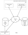
- FIG. 1 is a block diagram showing an exemplary image object detection system 100, according to some embodiments of the present disclosure.
- image object detection system 100 includes components for performing a training stage and an identification stage.
- image object detection system 100 includes a training system 110.
- image object identification system 100 includes a convolutional neural network (CNN) model-based identification system 120.
- CNN convolutional neural network
- image object detection system 100 may include greater or fewer of the components shown in FIG. 1 .
- image object detection system 100 may only include CNN model-based identification system 120.
- Image object identification system 100 optionally communicate over a network 130.
- network 130 may be replaced by wired data communication systems or devices.
- Communication network 130 may, for example be provided as a local area network (LAN); a wireless network; a cloud computing environment such as software as a service, platform as a service, infrastructure as a service; a client-server; a wide area network (WAN); or the like
- training system 110 communicates with an image database 140 over network 130 to receive images for use in training to identify different objects. As shown in FIG. 1 , training system 110 also communicates with a deep neural networks (DNN) database 150 over network 130 to save the trained neural networks developed by training system 110.
- DNN deep neural networks
- CNN model-based identification system 120 communicates with DNN database 150 over network 130 to receive different trained neural networks to identify objects in an image.
- CNN model-based identification system 120 also communicates with image database 140 over network 130 to access one or more images containing objects.
- CNN model-based identification system 120 may be local with respect to a medical imaging device 160.
- medical imaging device 160 and CNN model-based identification system 120 may be located in the same room of a medical facility/clinic.
- medical imaging device 160 may be remote with respect to CNN model-based identification system 120 and the data communication may be carried out via a network 130.
- the communication between training system 110 and medical imaging device 160 may also be implemented either locally or via network 130.
- CNN model-based identification system 120 and training system 110 may be implemented in a single data processing device, as indicated by the dashed line box in FIG. 1 .
- CNN model-based identification system 120 and training system 110 may be implemented as different software programs operating on the same hardware device.
- identification system 110 and training system 120 may be implemented using different data processing devices.
- Medical imaging device 160 may include an angiography device, a MRI imaging device, a CT imaging device, an X-ray imaging device, a positron emission tomography (PET) imaging device, an ultrasound imaging device, a fluoroscopic device, a single-photo emission computed tomography (SPECT) imaging device, or other medical imaging devices for obtaining one or more medical images of a patient.
- medical imaging device 160 may provide various kinds of medical images.
- the medical images may include angiogram images, MRI images, CT images, PET images, C-ray images, ultrasound images, SPECT images, etc.
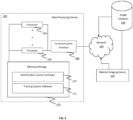
- FIG. 2 illustrates an embodiment of a data processing device 200.
- Data processing device 200 may implement each of the CNN model-based identification system 120 and training system 110, or both as image identification system 100.
- data processing device 200 includes one or more processors 260, a memory or storage device 270, and a communication interface 280.
- Memory/storage device 270 may store computer-executable instructions, such as identification system software 271 and training system software 272.
- Processors 260 may include one or more processor units, or a single processor unit with one or more cores.
- a "computing core" of processor 260 refers to either a processor unit or a core of a processor unit that is capable of executing instructions in a parallel-computing manner. For example, a computation task may be partitioned into multiple parallel branches or "threads", each branch/thread being executed by a computing core in parallel with other computing core(s).
- Processor 260 is communicatively coupled to memory/storage device 270 and configured to execute the computer executable instructions stored therein.
- processor 260 may execute identification system software 271 to implement functions of identification system 120.
- Processor 260 may also execute training system software 272 to implement functions of training system 110.
- processor device 260 may execute training system software 272 that interfaces with identification system software 271.
- Processor 260 communicates with image database 140.
- Image database 140 communicates with medical imaging device 160 and stores medical image data obtained by medical imaging device 160.
- image database 140 may include a plurality of devices located either in a central or a distributed manner.
- Processor 260 also communicates with medical imaging device 160 directly through communication interface 280.
- Processor 260 may include one or more general-purpose processing devices such as a microprocessor a central processing unit (CPU), a graphics processing unit (GPU), or the like. More particularly, processor 260 may include a Complex Instruction Set Computing (CISC) microprocessor, a Reduced Instruction Set Computing (RISC) microprocessor, a Very Long Instruction Word (VLIW) microprocessor, a processor implementing other instruction sets, or a processor implementing a combination of instruction sets. Processor 260 may also include one or more special purpose processing devices such as an Application Specific Integrated Circuit (ASIC), a Field Programmable Gate Array (FPGA), a Digital Signal Processor (DSP), a System on a Chip (SoC), or the like.
- ASIC Application Specific Integrated Circuit
- FPGA Field Programmable Gate Array
- DSP Digital Signal Processor
- SoC System on a Chip
- Memory/storage device 270 may include a read-only memory (ROM), a flash memory, a random access memory (RAM), a static memory, a flash memory, a hard drive, etc.
- memory/storage device 270 includes a computer-readable medium. While the computer-readable medium in an embodiment may be a single medium, the term "computer-readable medium" should be taken to include a single medium or multiple media (e.g., a centralized or distributed database, and/or associated caches and servers) that store the one or more sets of computer-executable instructions or data.
- computer-readable medium shall also be taken to include any medium that is capable of storing or encoding a set of instructions for execution by a computer such as the one or more processors 260, and that cause the computer to perform any one or more of the methodologies of the present disclosure.
- computer-readable medium should, accordingly, be taken to include, but not be limited to, solid-state memories, optical, and magnetic media.
- Communication interface 280 may include a network adaptor, a cable connector, a serial connector, a USB connector, a parallel connector, a high-speed data transmission adaptor, such as fiber, USB 3.0, thunderbolt, and the like.
- Interface 280 may also include a wireless network adaptor, such as WiFi adaptor, a telecommunication (3G, 4G, LTE and the like) adaptor, and the like.
- Communication interface 280 may provide the functionality of a local area network (LAN), a wireless network, a cloud computing environment (e.g., software as a service, platform as a service, infrastructure as a service, etc.), a client-server, a wide area network (WAN), and the like.
- Communication interface 280 communicates with medical imaging device 160 and image database 120 through network 130.
- Processors 260 may communicate with image database 120 and medical imaging device 160 via communication interface 280.
- FIG. 3 depicts an exemplary CNN model-based identification system 120.
- the identification system 120's functionality is performed in three stages: identifying an approximate position of an object of interest in an image, determining secondary positions of the object of interest in a sub-section of the image, and statistically analyzing secondary positions.
- identification system 120 includes a main deep neural network 321.
- Main deep neural network 321 communicates with a region of interest extractor 322 to extract a sub-section of the image which includes the approximate position, in order to identify the approximate position of the object in the image.
- identification system 120 includes one or more secondary deep neural networks 323.
- identification system 120 includes a statistical excluder 324, an averaging module 325, and a position converter 326.
- Each processor 260 may be running on a different data processing device 200.
- Each neural network in secondary deep neural networks 323 may be applied to a different sub-section of the image extracted by region of interest extractor 322.
- the number of secondary deep neural networks 323 may be determined by the shape of the object of interest.
- the number of secondary deep neural networks may also be determined by the type of the image supplied.
- an expanded view of main deep neural network 321 includes multiple sub-units that include convolution layers 351, and pooling layers 352.
- Each neural network optionally includes a loss layer 350 that includes a classifier unit 353.
- Loss layer 350 also includes a optimizer unit 354.
- Each of the neural networks which are part of secondary deep neural networks 323 may include sub-units similar to main deep neural network 321.
- Each of the sub-units may be implemented as separate software or as part of one integral software unit.
- the CNN model-based identification system 120 identifies an object of interest in a given image by first selecting the main deep neural network 321.
- the main deep neural network 321 and secondary deep neural networks 323 may be executed on the same data processing device 200 or on separate data processing devices 200.
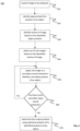
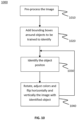
- FIG. 4 is a flow chart illustrating an exemplary object identification method 400, according to some embodiments of the present disclosure.
- method 400 may be performed by components of image object identification system 100, on data processing device 200, to identify one or more objects of interest. Although identification of only one object of interest is described as an example, it is contemplated that method 400 can be applied to identify a group of objects of interest at the same time.
- step 410 data processing device 200 accesses from image database 140 an image sent by the medical imaging device 160.
- the data processing device 200 may also receive the image directly from medical imaging device 160.
- the received image may be stored temporarily in memory/storage 270.
- main deep neural network 321 which is part of the identification system 120, identifies the approximate position of the object in the image received in step 410 and stored in memory 270.
- step 430 a sub-section of the image is identified based on the approximate position of the object determined in step 420 by the main deep neural network 321.
- a set of sub-images based on the sub-section extracted in step 430 are obtained by region of interest extractor 322.
- the number of sub-images matches the number of secondary deep neural networks 323.
- the sub-images are obtained using region of interest extractor 322 by adding different amounts of margin to the identified section of the image in step 430. In one embodiment an equal amount of margin is added to top, left, right and bottom sides of the identified section of the image. If adding margin results in crossing the boundary of a particular side of the image, then the margin amount is reduced to match the boundary of the particular side.
- a sub-image obtained in step 440 is provided as input to a neural network in secondary deep neural networks 323.
- the number of sub-images obtained may depend on the number of neural networks in secondary deep neural networks 323.
- the number of sub-images obtained in step 440 and the number of neural networks in secondary deep neural networks 323 is the same.
- respective sub-images obtained in step 440 may differ in size.
- the obtained sub-images may optionally differ in resolution, color, brightness, contrast, saturation and other image characteristics.
- step 460 a conditional check is made to determine whether there is a neural network in secondary deep neural networks 323 to which a sub-image obtained in step 440 needs to be applied. If the determination is 'yes' then step 450 is executed again and a sub-image is applied to the identified neural network in secondary deep neural networks 323. If not, the method proceeds to step 470.
- step 470 secondary positions obtained iteratively in steps 450 - 460 are statistically analyzed to determine the position of the object of interest in the image.
- the statistical analysis includes determining the average position of the object by averaging module 325 based on the secondary positions of the object identified by secondary deep neural networks 323 in step 450.
- Statistical analysis is performed by statistical excluder 324 to exclude some of the secondary positions obtained in step 450.
- the statistical excluder 324 determines the standard deviation of secondary positions and excludes only those positions which deviate more than one standard deviation from a mean position among secondary positions.
- Averaging module 325 calculates the average position based on the secondary positions not excluded by statistical excluder 324.
- FIG. 5 illustrates a process by which main deep neural network 321 analyzes an image to identify the approximate position of an object in step 420, according to some embodiments of the present disclosure.
- main deep neural network 321 has three layers of similar composition each including convolution layers 351, and pooling layers 352. The three layers are labeled Layer 1, Layer 2, and Layer 3. An output of each layer is input to the next layer.
- main deep neural network 321 may use a 3 x 3 kernel 501 in convolution layers 351 followed by sub-sampling twice using pooling layers 352.
- Kernel 501 helps filter relevant sections of the image and creates a set of feature maps 502.
- each of feature maps 502 may be sub-sampled using pooling layers 352. The final set of sub-sampled images is used to identify an approximate position of the object in the image.
- FIG. 6 illustrates a process by which a neural network in secondary deep neural networks 323 analyzes a sub-section of the image to identify a secondary position of step 450 of method 400, according to some embodiments of the present disclosure.
- the sub-section of the image is determined based on the identified approximate position by main deep neural network 321, as shown in FIG. 5 .
- secondary deep neural network 323 has three layers, each including a convolution layer 601 and pooling layers 604 respectively. The three layers are labeled Layer 1, Layer 2, and Layer 3. An output of each layer is input to the next layer.
- secondary deep neural networks 323 may use a 3 x 3 kernel 602 in convolution layer 601 followed by sub-sampling twice using pooling layers 604.
- Kernel 602 helps filter relevant sections of the image and creates a set of feature maps 603.
- each of feature maps 603 may be sub-sampled using pooling layers 604.
- a neural network in secondary deep neural networks 323 may use a 5 x 5 kernel 605 to filter certain set of features included in feature maps.
- FIG. 7 illustrates a statistical analysis process 700 performed by data processing device 200 for accurate identification of object position in an image according to some embodiments of the present disclosure.
- the secondary positions obtained in step 450 of method 400 by applying secondary deep neural networks 323 to the sub-images are statistically analyzed in step 470 using a three step process.
- the secondary positions are represented by bounding boxes such as bounding rectangles 711 around the object in the sub-image.
- sides 704 of the bounding rectangles 706 are used to calculate the respective standard deviations of top, left, right, and bottom sides using statistical excluder 324.
- the sides 708 of the rectangles 706 are compared against the standard deviation of each side obtained in step 702 by statistical excluder 324. Any side which deviates less than one standard deviation is included in calculating the location of the object in step 710.
- the process of including/excluding sides by the standard deviation criterion serves to filter the respective sides to yield filtered sides 712-718 corresponding to the four sides 704 of the rectangles 706.
- the filtered sides 712 - 718 are used to calculate the average sides using averaging module 325.
- the average sides determined by averaging module 325 are used to construct an average rectangle 720.
- a center 722 of average rectangle 720 is the position of the object in the image according to image object identification system 100. In some cases a side may fall outside one standard deviation and the average rectangle 720 may be missing a side, in which case center 722 is calculated from the available sides.
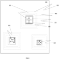
- FIG. 8 shows an illustration of a medical image 800 including output of fiducial markers 810, 820, and 830 identified by the identification system 120.
- each of three fiducial markers 810, 820, 830 is an object of interest indicated by a smaller white circle surrounded by a larger grey circle.
- the approximate position identified by main deep neural network 321 and secondary deep neural networks 323 is shown using a bounding rectangle as a bounding box.
- An exemplary rectangle 840 indicates the section of the image identified by main deep neural network 321 as the location of the object in step 430.
- An exemplary rectangle 850 indicates the sub-section of the image extracted by region of interest extractor 322 in step 440 of method 400.
- Rectangle 860 indicates the location of the object identified by a neural network in secondary deep neural networks 323 in step 450 of method 400.
- a set of sub-images obtained in step 440 of method 400 are indicated by rectangles of different sizes.
- the co-ordinates of the rectangles are input to statistic excluder 324 resulting in filtered sides 712-718 which are within one standard deviation. Filtered sides 712-718 are input to averaging module 325 to construct average rectangle 720.
- Center 721 of average rectangle 720 is input to the position converter 326 to translate the coordinates to the original co-ordinates in medical image 800 indicated by circle 810 as an object of interest.
- FIG. 9 depicts an exemplary configuration of model-based training system 110.
- System 110 includes multiple units. Each of the units may be implemented as a separate software module or be part of single software module. The units may run on different data processing devices 200.
- a contrast normalization module 931 pre-processes an image to aid in identification of a position of an object of interest.
- a DNN selector and trainer 932 may select the main deep neural network 321 for training. DNN selector and trainer 932 may also select the secondary deep neural networks 323 for training. DNN selector and trainer 932 may request DNN database 150 to provide the neural network to be trained. DNN selector and trainer 932 then trains the selected neutral network.
- An example of a training method is shown in FIG. 10 and described below. DNN selector and trainer 932 saves each trained main deep neural network 321 and secondary deep neural networks 323 to DNN database 150.
- the image used in training is modified using data augmentation tools such as a cropper 933, a flipper 934, and a color adjuster 935.
- data augmentation tools such as a cropper 933, a flipper 934, and a color adjuster 935.
- Cropper 933 crops the section of the image which has the object of interest, to obtain a smaller section of the image.
- Flipper 934 may in some cases flip the image horizontally or vertically to create new images.
- Color adjuster module 935 may modify the brightness, contrast, saturation and other image characteristics to create new images.
- Images generated by data augmentation tools are saved to image database 120 for future training. Some or all of the data augmentation tools are used together during the training stage.
- One or more data augmentation tools may be applied to an image in any order.
- Each data augmentation tool may be applied more than once to an image used for training neural networks.
- the image may be rotated multiple times to train the neural network to identify an object in an image irrespective of orientation.
- Data augmentation tools help improve the ability of the neural networks to identify an object in an image, irrespective of size, orientation and coarseness of the image.
- FIG. 10 is a flow chart illustrating an exemplary training method 1000, performed by training system 110, according to an exemplary embodiment.
- method 1000 may be performed by components of image object identification system 100, on data processing device 200, to train main deep neural network 321 and secondary deep neural networks 323.
- step 1010 data processing device 200 accesses an image from image database 140 and pre-processes the image using contrast normalization module 931.
- step 1020 bounding boxes are added around objects to be identified in the image. The bounding boxes border the object in the image with no buffer between them. This trains the system to not expect extra space between boxes when it identifies an object in an image.
- step 1030 an object is identified in the image by following steps in method 400.
- step 1040 data augmentation tools 933 - 935 are applied to the image to obtain a modified image with different characteristics. Images obtained in step 1040 are used to identify the position of the object in each modified image.
- a machine or computer readable storage medium may cause a machine to perform the functions or operations described, and includes any mechanism that stores information in a form accessible by a machine (e.g., computing device, electronic system, and the like), such as recordable/non-recordable media (e.g., read only memory (ROM), random access memory (RAM), magnetic disk storage media, optical storage media, flash memory devices, and the like).
- a communication interface includes any mechanism that interfaces to any of a hardwired, wireless, optical, and the like, medium to communicate to another device, such as a memory bus interface, a processor bus interface, an Internet connection, a disk controller, and the like.
- the communication interface can be configured by providing configuration parameters and/or sending signals to prepare the communication interface to provide a data signal describing the software content.
- the communication interface can be accessed via one or more commands or signals sent to the communication interface.
- the present disclosure also relates to a system for performing the operations herein.
- This system may be specially constructed for the required purposes, or it may comprise a general-purpose computer selectively activated or reconfigured by a computer program stored in the computer.
- a computer program may be stored in a computer readable storage medium, such as, but not limited to, any type of disk including floppy disks, optical disks, CDROMs, and magnetic-optical disks, read-only memories (ROMs), random access memories (RAMs), EPROMs, EEPROMs, magnetic or optical cards, or any type of media suitable for storing electronic instructions, each coupled to a computer system bus.
- Embodiments of the present disclosure may be implemented with computer-executable instructions.
- the computer-executable instructions may be organized into one or more computer-executable components or modules.
- Aspects of the disclosure may be implemented with any number and organization of such components or modules.
- aspects of the disclosure are not limited to the specific computer-executable instructions or the specific components or modules illustrated in the figures and described herein.
- Other embodiments may include different computer-executable instructions or components having more or less functionality than illustrated and described herein.
Landscapes
- Engineering & Computer Science (AREA)
- Theoretical Computer Science (AREA)
- Physics & Mathematics (AREA)
- General Physics & Mathematics (AREA)
- Health & Medical Sciences (AREA)
- Data Mining & Analysis (AREA)
- Evolutionary Computation (AREA)
- General Health & Medical Sciences (AREA)
- Software Systems (AREA)
- Artificial Intelligence (AREA)
- Multimedia (AREA)
- Computing Systems (AREA)
- Mathematical Physics (AREA)
- Computer Vision & Pattern Recognition (AREA)
- General Engineering & Computer Science (AREA)
- Life Sciences & Earth Sciences (AREA)
- Medical Informatics (AREA)
- Databases & Information Systems (AREA)
- Computational Linguistics (AREA)
- Biophysics (AREA)
- Biomedical Technology (AREA)
- Molecular Biology (AREA)
- Mathematical Optimization (AREA)
- Pure & Applied Mathematics (AREA)
- Mathematical Analysis (AREA)
- Computational Mathematics (AREA)
- Nuclear Medicine, Radiotherapy & Molecular Imaging (AREA)
- Evolutionary Biology (AREA)
- Radiology & Medical Imaging (AREA)
- Bioinformatics & Cheminformatics (AREA)
- Bioinformatics & Computational Biology (AREA)
- Operations Research (AREA)
- Probability & Statistics with Applications (AREA)
- Algebra (AREA)
- Quality & Reliability (AREA)
- Epidemiology (AREA)
- Public Health (AREA)
- Primary Health Care (AREA)
- Image Analysis (AREA)
Description
- This disclosure relates to identifying an object in an image. More specifically, this disclosure relates to devices and methods for using neural networks to identify an object of interest in an image.
- Fiducial markers are used in medical imaging technologies for reference. Image processing algorithms have been used to identify such markers in an image. Conventional image processing algorithms use templates limiting identification to a certain orientation and size of an object of interest. Identification of fiducial markers and other objects of interest is important in the field of medicine, since it can facilitate diagnosis and treatment.
- The use of deep neural networks can improve on conventional image processing techniques by allowing identification of objects of interest of any size or resolution in an image.
- An example of image processing based on neural networks is disclosed in Florian Chabot et al: "Deep MANTA: A Coarse-to-fine Many-Task Network for joint 2D and 3D vehicle analysis from monocular image", 22 March 2017, DOI: 10.1109/CVPR.2017.198. This paper discloses an approach, called Deep MANTA (Deep Many-Tasks), for many-task vehicle analysis from a given image. A robust convolutional network is introduced for simultaneous vehicle detection, part localization, visibility characterization and 3D dimension estimation. Its architecture is based on a coarse-to-fine object proposal that boosts vehicle detection. The Deep MANTA network is able to localize vehicle parts even if these parts are not visible. In the inference, the network's outputs are used by a real time robust pose estimation algorithm for fine orientation estimation and 3D vehicle localization.
- While use of deep neural networks seems promising, one challenge of deep networks is their requirement for large and preferably high-resolution training sets. The use of deep neural networks for identification of objects in medical imagery is constrained by the nature of medical images, which are often coarse and few in number. In addition, due to privacy concerns, large data sets of medical images are not freely available. These aspects of medical imagery make it difficult to take advantage of the features of deep neural networks.
- Accordingly, there is a need for a new automatic image object detection method to improve object detection performance on medical images or related fields.
- One aspect of the present invention provides a computer-implemented method for identifying an object in a medical image or series of medical images in accordance with
claim 1. - A further aspect of the present invention provides device for identifying objects in a medical image or series of images in accordance with claim 9.
- Another aspect of the present invention provides non-transitory computer-readable medium in accordance with claim 14.
- Further aspects of the present invention are disclosed by the dependent claims.
- The accompanying drawings, which constitute a part of this specification, illustrate several embodiments and, together with the description, serve to explain the disclosed principles.
-
FIG. 1 is a block diagram showing an exemplary image object identification system, according to some embodiments of the present disclosure. -
FIG. 2 is a block diagram showing an exemplary data processing device, according to some embodiments of the present disclosure. -
FIG. 3 depicts an exemplary convolutional neural network (CNN) model based identification system, according to some embodiments of the present disclosure. -
FIG. 4 is a flow chart illustrating an exemplary object identification method, performed by identification system software depicted inFIG. 2 , according to an exemplary embodiment. -
FIG. 5 illustrates a process by which a main deep neural network analyzes an image, according to some embodiments of the present disclosure. -
FIG. 6 illustrates a process by which a secondary deep neural network analyzes a sub-section of an image, according to some embodiments of the present disclosure. -
FIG. 7 illustrates a statistical analysis process for fine tuning an identified object position, according to some embodiments of the present disclosure. -
FIG. 8 is an illustration of a medical image with identified markers. -
FIG. 9 depicts an exemplary training system, according to some embodiments of the present disclosure. -
FIG. 10 is a flow chart illustrating an exemplary training method, performed by the training system ofFIG. 9 , according to an exemplary embodiment. - Exemplary embodiments are described with reference to the accompanying drawings. Wherever convenient, the same reference numbers are used throughout the drawings to refer to the same or like parts.
- Systems and methods consistent with the present disclosure are directed to identifying an object of interest in a medical image or a series of medical images. In a medical image the object of interest may include a tumor, an organ, etc. In some embodiments, the object of interest may include a fiducial marker.
- For example, an object shown in the medical image may be classified/identified in a binary manner: e.g., the object is present or is not present. In another example, the classification/identification may be carried out based on probability or likelihood. In some embodiments, an object may be identified as being, for example, highly likely present, indicating a high probability that the object is in fact present. Similarly, an object may be identified as being less likely present. The probability or likelihood associated with a classification or identification may be described by a confidence measure, such as a percentage number, to quantify the probability or likelihood.
- The spatial location of the object may be indicated by (X, Y) coordinates of the center of a bounding box e.g., a rectangle positioned to surround the object, or other appropriate coordinates if other spatial coordinate systems (e.g., cylindrical, spherical, etc.) are used.
- The medical image(s) may include images generated from various image modalities. For example, the medical image(s) may include an angiography image, a magnetic resonance imaging (MRI) image, a computed tomography (CT) image, an ultrasound image, or the like. The medical image(s) may be 2D or 3D. A 3D image may include a plurality of 2D slices.
-
FIG. 1 is a block diagram showing an exemplary imageobject detection system 100, according to some embodiments of the present disclosure. As shown inFIG. 1 , imageobject detection system 100 includes components for performing a training stage and an identification stage. To perform the training stage, imageobject detection system 100 includes atraining system 110. To perform the identification stage, imageobject identification system 100 includes a convolutional neural network (CNN) model-basedidentification system 120. In some embodiments, imageobject detection system 100 may include greater or fewer of the components shown inFIG. 1 . For example, when a CNN model for image object identification is pre-trained and provided, imageobject detection system 100 may only include CNN model-basedidentification system 120. Imageobject identification system 100 optionally communicate over anetwork 130. In some embodiments,network 130 may be replaced by wired data communication systems or devices.Communication network 130 may, for example be provided as a local area network (LAN); a wireless network; a cloud computing environment such as software as a service, platform as a service, infrastructure as a service; a client-server; a wide area network (WAN); or the like - As shown in
FIG. 1 ,training system 110 communicates with animage database 140 overnetwork 130 to receive images for use in training to identify different objects. As shown inFIG. 1 ,training system 110 also communicates with a deep neural networks (DNN)database 150 overnetwork 130 to save the trained neural networks developed bytraining system 110. - As shown in
Fig. 1 , CNN model-basedidentification system 120 communicates with DNNdatabase 150 overnetwork 130 to receive different trained neural networks to identify objects in an image. CNN model-basedidentification system 120 also communicates withimage database 140 overnetwork 130 to access one or more images containing objects. - In some embodiments, CNN model-based
identification system 120 may be local with respect to amedical imaging device 160. For example,medical imaging device 160 and CNN model-basedidentification system 120 may be located in the same room of a medical facility/clinic. In other embodiments,medical imaging device 160 may be remote with respect to CNN model-basedidentification system 120 and the data communication may be carried out via anetwork 130. Similarly, the communication betweentraining system 110 andmedical imaging device 160 may also be implemented either locally or vianetwork 130. - In some embodiments, CNN model-based
identification system 120 andtraining system 110 may be implemented in a single data processing device, as indicated by the dashed line box inFIG. 1 . For example, CNN model-basedidentification system 120 andtraining system 110 may be implemented as different software programs operating on the same hardware device. In other embodiments,identification system 110 andtraining system 120 may be implemented using different data processing devices. -
Medical imaging device 160 may include an angiography device, a MRI imaging device, a CT imaging device, an X-ray imaging device, a positron emission tomography (PET) imaging device, an ultrasound imaging device, a fluoroscopic device, a single-photo emission computed tomography (SPECT) imaging device, or other medical imaging devices for obtaining one or more medical images of a patient. Accordingly,medical imaging device 160 may provide various kinds of medical images. For example, the medical images may include angiogram images, MRI images, CT images, PET images, C-ray images, ultrasound images, SPECT images, etc. -
FIG. 2 illustrates an embodiment of adata processing device 200.Data processing device 200 may implement each of the CNN model-basedidentification system 120 andtraining system 110, or both asimage identification system 100. As shownFIG. 2 ,data processing device 200 includes one ormore processors 260, a memory orstorage device 270, and acommunication interface 280. Memory/storage device 270 may store computer-executable instructions, such asidentification system software 271 andtraining system software 272. -
Processors 260 may include one or more processor units, or a single processor unit with one or more cores. As used herein, a "computing core" ofprocessor 260 refers to either a processor unit or a core of a processor unit that is capable of executing instructions in a parallel-computing manner. For example, a computation task may be partitioned into multiple parallel branches or "threads", each branch/thread being executed by a computing core in parallel with other computing core(s). -
Processor 260 is communicatively coupled to memory/storage device 270 and configured to execute the computer executable instructions stored therein. For example,processor 260 may executeidentification system software 271 to implement functions ofidentification system 120.Processor 260 may also executetraining system software 272 to implement functions oftraining system 110. Optionally,processor device 260 may executetraining system software 272 that interfaces withidentification system software 271. -
Processor 260 communicates withimage database 140.Image database 140 communicates withmedical imaging device 160 and stores medical image data obtained bymedical imaging device 160. One skilled in the art would appreciate thatimage database 140 may include a plurality of devices located either in a central or a distributed manner.Processor 260 also communicates withmedical imaging device 160 directly throughcommunication interface 280. -
Processor 260 may include one or more general-purpose processing devices such as a microprocessor a central processing unit (CPU), a graphics processing unit (GPU), or the like. More particularly,processor 260 may include a Complex Instruction Set Computing (CISC) microprocessor, a Reduced Instruction Set Computing (RISC) microprocessor, a Very Long Instruction Word (VLIW) microprocessor, a processor implementing other instruction sets, or a processor implementing a combination of instruction sets.Processor 260 may also include one or more special purpose processing devices such as an Application Specific Integrated Circuit (ASIC), a Field Programmable Gate Array (FPGA), a Digital Signal Processor (DSP), a System on a Chip (SoC), or the like. - Memory/
storage device 270 may include a read-only memory (ROM), a flash memory, a random access memory (RAM), a static memory, a flash memory, a hard drive, etc. In some embodiments, memory/storage device 270 includes a computer-readable medium. While the computer-readable medium in an embodiment may be a single medium, the term "computer-readable medium" should be taken to include a single medium or multiple media (e.g., a centralized or distributed database, and/or associated caches and servers) that store the one or more sets of computer-executable instructions or data. The term "computer-readable medium" shall also be taken to include any medium that is capable of storing or encoding a set of instructions for execution by a computer such as the one ormore processors 260, and that cause the computer to perform any one or more of the methodologies of the present disclosure. The term "computer-readable medium" should, accordingly, be taken to include, but not be limited to, solid-state memories, optical, and magnetic media. -
Communication interface 280 may include a network adaptor, a cable connector, a serial connector, a USB connector, a parallel connector, a high-speed data transmission adaptor, such as fiber, USB 3.0, thunderbolt, and the like.Interface 280 may also include a wireless network adaptor, such as WiFi adaptor, a telecommunication (3G, 4G, LTE and the like) adaptor, and the like.Communication interface 280 may provide the functionality of a local area network (LAN), a wireless network, a cloud computing environment (e.g., software as a service, platform as a service, infrastructure as a service, etc.), a client-server, a wide area network (WAN), and the like.Communication interface 280 communicates withmedical imaging device 160 andimage database 120 throughnetwork 130.Processors 260 may communicate withimage database 120 andmedical imaging device 160 viacommunication interface 280. -
FIG. 3 depicts an exemplary CNN model-basedidentification system 120. Theidentification system 120's functionality is performed in three stages: identifying an approximate position of an object of interest in an image, determining secondary positions of the object of interest in a sub-section of the image, and statistically analyzing secondary positions. To perform identification of the approximate position of an object of interest in an image,identification system 120 includes a main deepneural network 321. Main deepneural network 321 communicates with a region ofinterest extractor 322 to extract a sub-section of the image which includes the approximate position, in order to identify the approximate position of the object in the image. To perform identification of secondary positions of the object in the sub-section of the image,identification system 120 includes one or more secondary deepneural networks 323. To perform the final stage of statistical analysis of the secondary positions,identification system 120 includes astatistical excluder 324, anaveraging module 325, and aposition converter 326. Eachprocessor 260 may be running on a differentdata processing device 200. - Each neural network in secondary deep
neural networks 323 may be applied to a different sub-section of the image extracted by region ofinterest extractor 322. The number of secondary deepneural networks 323 may be determined by the shape of the object of interest. The number of secondary deep neural networks may also be determined by the type of the image supplied. - As shown in
Fig. 3 , an expanded view of main deepneural network 321 includes multiple sub-units that includeconvolution layers 351, and pooling layers 352. Each neural network optionally includes aloss layer 350 that includes aclassifier unit 353.Loss layer 350 also includes aoptimizer unit 354. Each of the neural networks which are part of secondary deepneural networks 323 may include sub-units similar to main deepneural network 321. Each of the sub-units may be implemented as separate software or as part of one integral software unit. - The CNN model-based
identification system 120 identifies an object of interest in a given image by first selecting the main deepneural network 321. The main deepneural network 321 and secondary deepneural networks 323 may be executed on the samedata processing device 200 or on separatedata processing devices 200. -
FIG. 4 is a flow chart illustrating an exemplaryobject identification method 400, according to some embodiments of the present disclosure. In some embodiments,method 400 may be performed by components of imageobject identification system 100, ondata processing device 200, to identify one or more objects of interest. Although identification of only one object of interest is described as an example, it is contemplated thatmethod 400 can be applied to identify a group of objects of interest at the same time. - As shown in
FIG. 4 , instep 410,data processing device 200 accesses fromimage database 140 an image sent by themedical imaging device 160. Thedata processing device 200 may also receive the image directly frommedical imaging device 160. The received image may be stored temporarily in memory/storage 270. - In
step 420, main deepneural network 321, which is part of theidentification system 120, identifies the approximate position of the object in the image received instep 410 and stored inmemory 270. - In
step 430, a sub-section of the image is identified based on the approximate position of the object determined instep 420 by the main deepneural network 321. - In
step 440, a set of sub-images based on the sub-section extracted instep 430 are obtained by region ofinterest extractor 322. In one embodiment, the number of sub-images matches the number of secondary deepneural networks 323. In one embodiment the sub-images are obtained using region ofinterest extractor 322 by adding different amounts of margin to the identified section of the image instep 430. In one embodiment an equal amount of margin is added to top, left, right and bottom sides of the identified section of the image. If adding margin results in crossing the boundary of a particular side of the image, then the margin amount is reduced to match the boundary of the particular side. - In
step 450, a sub-image obtained instep 440 is provided as input to a neural network in secondary deepneural networks 323. The number of sub-images obtained may depend on the number of neural networks in secondary deepneural networks 323. In one embodiment, the number of sub-images obtained instep 440 and the number of neural networks in secondary deepneural networks 323 is the same. In one embodiment, respective sub-images obtained instep 440 may differ in size. The obtained sub-images may optionally differ in resolution, color, brightness, contrast, saturation and other image characteristics. - At
step 460, a conditional check is made to determine whether there is a neural network in secondary deepneural networks 323 to which a sub-image obtained instep 440 needs to be applied. If the determination is 'yes' then step 450 is executed again and a sub-image is applied to the identified neural network in secondary deepneural networks 323. If not, the method proceeds to step 470. - In
step 470, secondary positions obtained iteratively in steps 450 - 460 are statistically analyzed to determine the position of the object of interest in the image. The statistical analysis includes determining the average position of the object by averagingmodule 325 based on the secondary positions of the object identified by secondary deepneural networks 323 instep 450. Statistical analysis is performed bystatistical excluder 324 to exclude some of the secondary positions obtained instep 450. Thestatistical excluder 324 determines the standard deviation of secondary positions and excludes only those positions which deviate more than one standard deviation from a mean position among secondary positions. Averagingmodule 325 calculates the average position based on the secondary positions not excluded bystatistical excluder 324. -
FIG. 5 illustrates a process by which main deepneural network 321 analyzes an image to identify the approximate position of an object instep 420, according to some embodiments of the present disclosure. As shown inFIG. 5 , in some embodiments, main deepneural network 321 has three layers of similar composition each including convolution layers 351, and pooling layers 352. The three layers are labeledLayer 1,Layer 2, andLayer 3. An output of each layer is input to the next layer. For example and without limitation, as shown inFIG. 5 , main deepneural network 321 may use a 3 x 3kernel 501 inconvolution layers 351 followed by sub-sampling twice using pooling layers 352. -
Kernel 501 helps filter relevant sections of the image and creates a set of feature maps 502. In some embodiments, each of feature maps 502 may be sub-sampled using pooling layers 352. The final set of sub-sampled images is used to identify an approximate position of the object in the image. - As show in
FIG. 5 , in each of the layers 1-3, input to and output ofconvolution layers 351 and poolinglayers 352 are represented by matrices. Applying convolution layers 351 or poolinglayers 352 to their respective inputs (on the right hand side) is depicted byapplication symbol 504. -
FIG. 6 illustrates a process by which a neural network in secondary deepneural networks 323 analyzes a sub-section of the image to identify a secondary position ofstep 450 ofmethod 400, according to some embodiments of the present disclosure. The sub-section of the image is determined based on the identified approximate position by main deepneural network 321, as shown inFIG. 5 . As shown inFIG. 6 , in some embodiments, secondary deepneural network 323 has three layers, each including aconvolution layer 601 and poolinglayers 604 respectively. The three layers are labeledLayer 1,Layer 2, andLayer 3. An output of each layer is input to the next layer. For example and without limitation, as shown inFIG. 6 , secondary deepneural networks 323 may use a 3 x 3kernel 602 inconvolution layer 601 followed by sub-sampling twice using pooling layers 604. -
Kernel 602 helps filter relevant sections of the image and creates a set of feature maps 603. In some embodiments, each of feature maps 603 may be sub-sampled using pooling layers 604. In some embodiments, a neural network in secondary deepneural networks 323 may use a 5 x 5kernel 605 to filter certain set of features included in feature maps. - As show in
FIG. 6 , in each of the layers 1-3, input to and output ofconvolution layer 601 and poolinglayers 602 are represented by matrices. Applyingconvolution layer 601 or poolinglayers 602 to their respective inputs (on the right hand side) is depicted byapplication symbol 605. -
FIG. 7 illustrates astatistical analysis process 700 performed bydata processing device 200 for accurate identification of object position in an image according to some embodiments of the present disclosure. As shown inFIG. 7 , in some embodiments, the secondary positions obtained instep 450 ofmethod 400 by applying secondary deepneural networks 323 to the sub-images, are statistically analyzed instep 470 using a three step process. In some embodiments, the secondary positions are represented by bounding boxes such as bounding rectangles 711 around the object in the sub-image. - In
step 702,sides 704 of the boundingrectangles 706 are used to calculate the respective standard deviations of top, left, right, and bottom sides usingstatistical excluder 324. Instep 708, thesides 708 of therectangles 706 are compared against the standard deviation of each side obtained instep 702 bystatistical excluder 324. Any side which deviates less than one standard deviation is included in calculating the location of the object instep 710. The process of including/excluding sides by the standard deviation criterion serves to filter the respective sides to yield filtered sides 712-718 corresponding to the foursides 704 of therectangles 706. Instep 710, the filtered sides 712 - 718 are used to calculate the average sides usingaveraging module 325. The average sides determined by averagingmodule 325 are used to construct anaverage rectangle 720. Acenter 722 ofaverage rectangle 720 is the position of the object in the image according to imageobject identification system 100. In some cases a side may fall outside one standard deviation and theaverage rectangle 720 may be missing a side, in whichcase center 722 is calculated from the available sides. -
FIG. 8 shows an illustration of amedical image 800 including output offiducial markers identification system 120. As shown inFig. 8 , each of threefiducial markers FIG. 8 , in some embodiments the approximate position identified by main deepneural network 321 and secondary deepneural networks 323 is shown using a bounding rectangle as a bounding box. Anexemplary rectangle 840 indicates the section of the image identified by main deepneural network 321 as the location of the object instep 430. Anexemplary rectangle 850 indicates the sub-section of the image extracted by region ofinterest extractor 322 instep 440 ofmethod 400.Rectangle 860 indicates the location of the object identified by a neural network in secondary deepneural networks 323 instep 450 ofmethod 400. A set of sub-images obtained instep 440 ofmethod 400 are indicated by rectangles of different sizes. The co-ordinates of the rectangles are input tostatistic excluder 324 resulting in filtered sides 712-718 which are within one standard deviation. Filtered sides 712-718 are input to averagingmodule 325 to constructaverage rectangle 720. Center 721 ofaverage rectangle 720 is input to theposition converter 326 to translate the coordinates to the original co-ordinates inmedical image 800 indicated bycircle 810 as an object of interest. -
FIG. 9 depicts an exemplary configuration of model-basedtraining system 110.System 110 includes multiple units. Each of the units may be implemented as a separate software module or be part of single software module. The units may run on differentdata processing devices 200. In some embodiments, acontrast normalization module 931 pre-processes an image to aid in identification of a position of an object of interest. In some embodiments, a DNN selector andtrainer 932 may select the main deepneural network 321 for training. DNN selector andtrainer 932 may also select the secondary deepneural networks 323 for training. DNN selector andtrainer 932 may requestDNN database 150 to provide the neural network to be trained. DNN selector andtrainer 932 then trains the selected neutral network. An example of a training method is shown inFIG. 10 and described below. DNN selector andtrainer 932 saves each trained main deepneural network 321 and secondary deepneural networks 323 toDNN database 150. - In some embodiments, the image used in training is modified using data augmentation tools such as a
cropper 933, a flipper 934, and acolor adjuster 935. The constraint of limited medical image availability can be resolved using the data augmentation tools.Cropper 933 crops the section of the image which has the object of interest, to obtain a smaller section of the image. Flipper 934 may in some cases flip the image horizontally or vertically to create new images.Color adjuster module 935 may modify the brightness, contrast, saturation and other image characteristics to create new images. Images generated by data augmentation tools are saved to imagedatabase 120 for future training. Some or all of the data augmentation tools are used together during the training stage. One or more data augmentation tools may be applied to an image in any order. Each data augmentation tool may be applied more than once to an image used for training neural networks. In some embodiments the image may be rotated multiple times to train the neural network to identify an object in an image irrespective of orientation. Data augmentation tools help improve the ability of the neural networks to identify an object in an image, irrespective of size, orientation and coarseness of the image. -
FIG. 10 is a flow chart illustrating anexemplary training method 1000, performed bytraining system 110, according to an exemplary embodiment. In some embodiments,method 1000 may be performed by components of imageobject identification system 100, ondata processing device 200, to train main deepneural network 321 and secondary deepneural networks 323. - Persons of ordinary skill will now appreciate that the present disclosure is not limited to devices and methods for identifying an object of interest in a medical image and may be practiced with equal effect for identifying an object of interest in other types of and classes of images.
- As show in
FIG. 10 , instep 1010,data processing device 200 accesses an image fromimage database 140 and pre-processes the image usingcontrast normalization module 931. Instep 1020, bounding boxes are added around objects to be identified in the image. The bounding boxes border the object in the image with no buffer between them. This trains the system to not expect extra space between boxes when it identifies an object in an image. Instep 1030, an object is identified in the image by following steps inmethod 400. Instep 1040, data augmentation tools 933 - 935 are applied to the image to obtain a modified image with different characteristics. Images obtained instep 1040 are used to identify the position of the object in each modified image. - Various operations or functions are described herein, which may be implemented or defined as software code or instructions. Such content may be directly executable ("object" or "executable" form), source code, or difference code ("delta" or "patch" code). Software implementations of the embodiments described herein may be provided via an article of manufacture with the code or instructions stored thereon, or via a method of operating a communication interface to send data via the communication interface. A machine or computer readable storage medium may cause a machine to perform the functions or operations described, and includes any mechanism that stores information in a form accessible by a machine (e.g., computing device, electronic system, and the like), such as recordable/non-recordable media (e.g., read only memory (ROM), random access memory (RAM), magnetic disk storage media, optical storage media, flash memory devices, and the like). A communication interface includes any mechanism that interfaces to any of a hardwired, wireless, optical, and the like, medium to communicate to another device, such as a memory bus interface, a processor bus interface, an Internet connection, a disk controller, and the like. The communication interface can be configured by providing configuration parameters and/or sending signals to prepare the communication interface to provide a data signal describing the software content. The communication interface can be accessed via one or more commands or signals sent to the communication interface.
- The present disclosure also relates to a system for performing the operations herein. This system may be specially constructed for the required purposes, or it may comprise a general-purpose computer selectively activated or reconfigured by a computer program stored in the computer. Such a computer program may be stored in a computer readable storage medium, such as, but not limited to, any type of disk including floppy disks, optical disks, CDROMs, and magnetic-optical disks, read-only memories (ROMs), random access memories (RAMs), EPROMs, EEPROMs, magnetic or optical cards, or any type of media suitable for storing electronic instructions, each coupled to a computer system bus.
- Embodiments of the present disclosure may be implemented with computer-executable instructions. The computer-executable instructions may be organized into one or more computer-executable components or modules. Aspects of the disclosure may be implemented with any number and organization of such components or modules. For example, aspects of the disclosure are not limited to the specific computer-executable instructions or the specific components or modules illustrated in the figures and described herein. Other embodiments may include different computer-executable instructions or components having more or less functionality than illustrated and described herein.
- The words "comprising," "having," "containing," and "including," and other similar forms are intended to be equivalent in meaning and be interpreted as open ended, in that, an item or items following any one of these words is not meant to be an exhaustive listing of such item or items, or meant to be limited to only the listed item or items. In addition, the singular forms "a," "an," and "the" are intended to include plural references, unless the context clearly dictates otherwise.
Claims (14)
- A computer-implemented method for identifying an object in a medical image or series of medical images, the method comprising:receiving (410), by one or more processors (260), a medical image comprising one or more objects of interest, wherein the one or more objects of interest comprise any of a tumor, an organ, or a fiducial marker;using (420) a first neural network (321) to identify an approximate position of an object of interest in the received image;identifying (430), by the one or more processors (260), based on the identified approximate position, a section of the received image that includes the object of interest;obtaining (440), by the one or more processors (260), a plurality of sub-images corresponding to different sub-sections of the identified section of the received image;applying (450) the plurality of sub-images to a plurality of second neural networks (323), each of the second neural networks determining a respective position of the object of interest, such that the plurality of second neural networks (323) determine a respective plurality of secondary positions of the object of interest; anddetermining the average position of the object based on the secondary positions of the object determined by the plurality of second neural networks (323), wherein the determined average position is determined on the basis of an average position of the secondary positions excluding positions which deviate more than one standard deviation from a mean position among the secondary positions, wherein prior to receiving the medical image comprising one or more objects of interest, the method includes:training, by one or more processors (260), the first neural network (321) to learn to identify the approximate position of the object of interest in a medical training image; andtraining, by one or more processors (260), the plurality of second neural networks (323) to learn to identify the position of the object of interest in the medical training image.
- The method of claim 1, wherein obtaining (440) the plurality of sub-images corresponding to the identified section of the received image includes:creating a first sub-image by adding a first margin to the identified section of the image including the object of interest; andcreating a second sub-image by adding a second margin of a different amount from the first margin to the identified section of the image including the object of interest.
- The method of claim 1, further comprising:identifying, by the one or more processors (260), based on each determined secondary position in each of the sub-images a corresponding section of the sub-image that includes the object of interest; anddetermining bounding rectangles matching edges of each of the identified sections.
- The method of claim 3, further comprising:determining average top, left, right, and bottom sides based on sides of the bounding rectangles;constructing an average rectangle using the average sides;calculating a center of the average rectangle;translating the center of the average rectangle to a position in the received image; andidentifying the translated position as a position of the object of interest in the received image.
- The method of claim 4, further comprising:determining standard deviations of top, left, right, and bottom sides based on the sides of the bounding rectangles of the identified sections of the sub-images; andremoving sides of the bounding rectangles which are more than one standard deviation of the respective side.
- The method of claim 1, wherein the training of the first neural network (321) to learn to identify the approximate position of the object of interest includes:
pre-processing (1010) the medical training image by adjusting one or more color characteristics of the image. - The method of claim 1, wherein training the first neural network (321) to learn to identify the approximate position of the object of interest includes:generating one or more images of the medical training image by:cropping a section of the medical training image which includes the object of interest,flipping the medical training image,rotating the medical training image, oradjusting color characteristics of the medical training image; andapplying the generated image to the first neural network to identify the position of the object of interest in the generated image.
- The method of claim 1, wherein training the second neural network (323) to learn to identify the position of the object of interest includes:obtaining, by the one or more processors (260), a training sub-image including the position of the object of interest identified by the first neural network (321); andapplying the training sub-image to the second neural network (323) to determine a position of the object of interest.
- A device (120) for identifying objects in a medical image or a series of images, the device comprising:an input interface (280) that receives a medical image comprising one or more objects of interest, wherein the one or more objects of interest comprise any of a tumor, an organ, or a fiducial marker;at least one storage device configured to store the received image; andone or more processors (260) configured to:use (420) a first neural network (321) to identify an approximate position of an object of interest;identify (430), based on the identified approximate position, a section of the received image that includes the object of interest;obtain (440) a plurality of sub-images corresponding to different sub-sections of the identified section of the received image;apply (450) the plurality of sub-images to a plurality of second neural networks (323), each of the second neural networks determining a respective position of the object of interest, such that the plurality of second neural networks (323) determine a respective plurality of secondary positions of first object of interest; anddetermine the average position of the object based on the secondary positions of the object determined by the plurality of second neural networks (323), wherein the determined average position is determined on the basis of an average position of the secondary positions excluding positions which deviate more than one standard deviation from a mean position among the secondary positions, wherein prior to receiving the medical image comprising one or more objects of interest, the one or more processors (260) are configured to:train the first neural network (321) to learn to identify the approximate position of the object of interest in a medical training image; andtrain the plurality of second neural networks (323) to learn to identify the position of the object of interest in the medical training image.
- The device of claim 9, wherein the one or more processors (260) being further configured to:create a first sub-image by adding a first margin to the identified section of the image including the object of interest; andcreate a second sub-image by adding a second margin of a different amount from the first margin to the identified section of the image including the object of interest.
- The device of claim 9, the one or more processors (260) being further configured to:identify, based on each determined secondary position in each of the sub-images a corresponding section of the sub-image that includes the object of interest; anddetermine bounding rectangles matching edges of each of the each identified sections.
- The device of claim 11, the one or more processors (260) being further configured to:determine average top, left, right, and bottom sides based on sides of the bounding rectangles;construct an average rectangle using the average sides; andcalculate center of the average rectangle; andtranslate a center of the average rectangle to a position in the received image; andidentify the translated position as a position of the object of interest in the received image.
- The device of claim 11, wherein the one or more processors (260) being further configured to:determine standard deviation of top, left, right, and bottom sides based on the sides of the bounding rectangles of the identified sections of the sub-images; andremove sides of the bounding rectangles which are more than one standard deviation of the respective side.
- A non-transitory computer-readable medium storing instructions that, when executable by one or more processors (260), cause the one or more processors (260) to perform a method for identifying an object in a medical image in accordance with any of claims 1-8.
Applications Claiming Priority (1)
| Application Number | Priority Date | Filing Date | Title |
|---|---|---|---|
| US15/947,693 US10546389B2 (en) | 2018-04-06 | 2018-04-06 | Devices and methods for identifying an object in an image |
Publications (2)
| Publication Number | Publication Date |
|---|---|
| EP3570216A1 EP3570216A1 (en) | 2019-11-20 |
| EP3570216B1 true EP3570216B1 (en) | 2024-04-17 |
Family
ID=66102538
Family Applications (1)
| Application Number | Title | Priority Date | Filing Date |
|---|---|---|---|
| EP19167888.7A Active EP3570216B1 (en) | 2018-04-06 | 2019-04-08 | Devices and methods for identifying an object in an image |
Country Status (3)
| Country | Link |
|---|---|
| US (1) | US10546389B2 (en) |
| EP (1) | EP3570216B1 (en) |
| CN (1) | CN110348467B (en) |
Families Citing this family (12)
| Publication number | Priority date | Publication date | Assignee | Title |
|---|---|---|---|---|
| JP7398377B2 (en) | 2018-01-10 | 2023-12-14 | アンスティテュ・ドゥ・ルシェルシュ・シュール・レ・カンセール・ドゥ・ラパレイユ・ディジェスティフ-イ・エール・セ・ア・デ | Automatic segmentation process of 3D medical images by several neural networks through structured convolution according to the geometry of 3D medical images |
| JP7240403B2 (en) | 2018-01-10 | 2023-03-15 | アンスティテュ・ドゥ・ルシェルシュ・シュール・レ・カンセール・ドゥ・ラパレイユ・ディジェスティフ-イ・エール・セ・ア・デ | Automatic segmentation process of 3D medical images by one or several neural networks through structured convolution according to the anatomical geometry of the 3D medical images |
| KR102708715B1 (en) * | 2018-11-16 | 2024-09-24 | 삼성전자주식회사 | Image processing apparatus and operating method for the same |
| WO2021097675A1 (en) * | 2019-11-19 | 2021-05-27 | 中国科学院深圳先进技术研究院 | Smart diagnosis assistance method and terminal based on medical images |
| US20230245753A1 (en) * | 2020-04-13 | 2023-08-03 | Kaliber Labs Inc. | Systems and methods for ai-assisted surgery |
| EP4135567A4 (en) | 2020-04-13 | 2024-06-12 | Kaliber Labs Inc. | Systems and methods for computer-assisted shape measurements in video |
| CN113688658B (en) * | 2020-05-18 | 2024-06-28 | 华为云计算技术有限公司 | Object identification method, device, equipment and medium |
| US12537091B2 (en) | 2021-04-12 | 2026-01-27 | Kaliber Labs Inc. | Systems and methods for AI-assisted medical image annotation |
| WO2022221341A1 (en) | 2021-04-12 | 2022-10-20 | Chandra Jonelagadda | Systems and methods for using image analysis in superior capsule reconstruction |
| US12504991B1 (en) * | 2021-11-30 | 2025-12-23 | Teradata Us, Inc. | Workload memory management to achieve service level goals in a highly concurrent database system executing in a cloud and/or on-prem systems |
| US12233912B2 (en) | 2022-01-10 | 2025-02-25 | Ford Global Technologies, Llc | Efficient neural networks |
| CN117891165B (en) * | 2023-12-15 | 2025-11-28 | 上海大学 | Controller design method and system based on improved structured neural network |
Family Cites Families (7)
| Publication number | Priority date | Publication date | Assignee | Title |
|---|---|---|---|---|
| US9224068B1 (en) * | 2013-12-04 | 2015-12-29 | Google Inc. | Identifying objects in images |
| US9418319B2 (en) * | 2014-11-21 | 2016-08-16 | Adobe Systems Incorporated | Object detection using cascaded convolutional neural networks |
| US10410096B2 (en) * | 2015-07-09 | 2019-09-10 | Qualcomm Incorporated | Context-based priors for object detection in images |
| US10049307B2 (en) * | 2016-04-04 | 2018-08-14 | International Business Machines Corporation | Visual object recognition |
| US10255522B2 (en) * | 2016-06-17 | 2019-04-09 | Facebook, Inc. | Generating object proposals using deep-learning models |
| US10496895B2 (en) * | 2017-03-28 | 2019-12-03 | Facebook, Inc. | Generating refined object proposals using deep-learning models |
| CN107679451A (en) * | 2017-08-25 | 2018-02-09 | 百度在线网络技术(北京)有限公司 | Establish the method, apparatus, equipment and computer-readable storage medium of human face recognition model |
-
2018
- 2018-04-06 US US15/947,693 patent/US10546389B2/en active Active
-
2019
- 2019-04-04 CN CN201910272119.7A patent/CN110348467B/en active Active
- 2019-04-08 EP EP19167888.7A patent/EP3570216B1/en active Active
Also Published As
| Publication number | Publication date |
|---|---|
| US20190311493A1 (en) | 2019-10-10 |
| EP3570216A1 (en) | 2019-11-20 |
| CN110348467B (en) | 2024-01-05 |
| US10546389B2 (en) | 2020-01-28 |
| CN110348467A (en) | 2019-10-18 |
Similar Documents
| Publication | Publication Date | Title |
|---|---|---|
| US10546389B2 (en) | Devices and methods for identifying an object in an image | |
| US10346986B2 (en) | System and methods for image segmentation using convolutional neural network | |
| EP3828825B1 (en) | METHOD AND DEVICE FOR IMAGE SEGMENTATION, DIAGNOSTIC SYSTEM, STORAGE MEDIUM AND COMPUTER DEVICE | |
| AU2017315674B2 (en) | Image segmentation using neural network method | |
| CN109003267B (en) | Computer-implemented method and system for automatically detecting target object from 3D image | |
| CN109410188B (en) | System and method for segmenting medical images | |
| EP3735176A1 (en) | Systems and methods for the segmentation of multi-modal image data | |
| CN108986115B (en) | Medical image segmentation method and device and intelligent terminal | |
| KR102349515B1 (en) | Tumor automatic segmentation based on deep learning in a medical image | |
| CN118762005B (en) | Coordinate positioning method and system for kidney stones based on preoperative CT and intraoperative ultrasound images | |
| US9672600B2 (en) | Clavicle suppression in radiographic images | |
| CN112712507B (en) | A method and device for determining calcified areas of coronary arteries | |
| JPWO2020174770A1 (en) | Domain-specific devices, methods and programs, learning devices, methods and programs, and classifiers | |
| US12026934B2 (en) | Systems and methods for training a convolutional neural network that is robust to missing input information | |
| JP7105918B2 (en) | AREA IDENTIFICATION APPARATUS, METHOD AND PROGRAM | |
| KR102102369B1 (en) | Method and apparatus for estimating matching performance | |
| CN121707917A (en) | Tumor image segmentation system and method | |
| CN122067048A (en) | Model training method and program product for medical image | |
| CN121883508A (en) | A Two-Dimensional Multi-View Brain Tumor Medical Image Segmentation Method and System Based on Vision Mamba Temporal Model |
Legal Events
| Date | Code | Title | Description |
|---|---|---|---|
| PUAI | Public reference made under article 153(3) epc to a published international application that has entered the european phase |
Free format text: ORIGINAL CODE: 0009012 |
|
| STAA | Information on the status of an ep patent application or granted ep patent |
Free format text: STATUS: THE APPLICATION HAS BEEN PUBLISHED |
|
| AK | Designated contracting states |
Kind code of ref document: A1 Designated state(s): AL AT BE BG CH CY CZ DE DK EE ES FI FR GB GR HR HU IE IS IT LI LT LU LV MC MK MT NL NO PL PT RO RS SE SI SK SM TR |
|
| AX | Request for extension of the european patent |
Extension state: BA ME |
|
| STAA | Information on the status of an ep patent application or granted ep patent |
Free format text: STATUS: REQUEST FOR EXAMINATION WAS MADE |
|
| 17P | Request for examination filed |
Effective date: 20200519 |
|
| RBV | Designated contracting states (corrected) |
Designated state(s): AL AT BE BG CH CY CZ DE DK EE ES FI FR GB GR HR HU IE IS IT LI LT LU LV MC MK MT NL NO PL PT RO RS SE SI SK SM TR |
|
| STAA | Information on the status of an ep patent application or granted ep patent |
Free format text: STATUS: EXAMINATION IS IN PROGRESS |
|
| 17Q | First examination report despatched |
Effective date: 20211102 |
|
| REG | Reference to a national code |
Ref country code: DE Ref legal event code: R079 Free format text: PREVIOUS MAIN CLASS: G06K0009620000 Ipc: G06V0010820000 Ref country code: DE Ref legal event code: R079 Ref document number: 602019050315 Country of ref document: DE Free format text: PREVIOUS MAIN CLASS: G06K0009620000 Ipc: G06V0010820000 |
|
| RIC1 | Information provided on ipc code assigned before grant |
Ipc: G06V 10/24 20220101ALI20230815BHEP Ipc: G06V 10/22 20220101ALI20230815BHEP Ipc: G06V 10/82 20220101AFI20230815BHEP |
|
| GRAP | Despatch of communication of intention to grant a patent |
Free format text: ORIGINAL CODE: EPIDOSNIGR1 |
|
| STAA | Information on the status of an ep patent application or granted ep patent |
Free format text: STATUS: GRANT OF PATENT IS INTENDED |
|
| RAP3 | Party data changed (applicant data changed or rights of an application transferred) |
Owner name: ELEKTA AB (PUBL) |
|
| INTG | Intention to grant announced |
Effective date: 20231002 |
|
| GRAJ | Information related to disapproval of communication of intention to grant by the applicant or resumption of examination proceedings by the epo deleted |
Free format text: ORIGINAL CODE: EPIDOSDIGR1 |
|
| STAA | Information on the status of an ep patent application or granted ep patent |
Free format text: STATUS: EXAMINATION IS IN PROGRESS |
|
| GRAP | Despatch of communication of intention to grant a patent |
Free format text: ORIGINAL CODE: EPIDOSNIGR1 |
|
| STAA | Information on the status of an ep patent application or granted ep patent |
Free format text: STATUS: GRANT OF PATENT IS INTENDED |
|
| GRAS | Grant fee paid |
Free format text: ORIGINAL CODE: EPIDOSNIGR3 |
|
| INTC | Intention to grant announced (deleted) | ||
| GRAA | (expected) grant |
Free format text: ORIGINAL CODE: 0009210 |
|
| STAA | Information on the status of an ep patent application or granted ep patent |
Free format text: STATUS: THE PATENT HAS BEEN GRANTED |
|
| INTG | Intention to grant announced |
Effective date: 20240229 |
|
| AK | Designated contracting states |
Kind code of ref document: B1 Designated state(s): AL AT BE BG CH CY CZ DE DK EE ES FI FR GB GR HR HU IE IS IT LI LT LU LV MC MK MT NL NO PL PT RO RS SE SI SK SM TR |
|
| REG | Reference to a national code |
Ref country code: GB Ref legal event code: FG4D |
|
| REG | Reference to a national code |
Ref country code: CH Ref legal event code: EP |
|
| P01 | Opt-out of the competence of the unified patent court (upc) registered |
Effective date: 20240328 |
|
| REG | Reference to a national code |
Ref country code: DE Ref legal event code: R096 Ref document number: 602019050315 Country of ref document: DE |
|
| REG | Reference to a national code |
Ref country code: IE Ref legal event code: FG4D |
|
| REG | Reference to a national code |
Ref country code: LT Ref legal event code: MG9D |
|
| REG | Reference to a national code |
Ref country code: NL Ref legal event code: MP Effective date: 20240417 |
|
| REG | Reference to a national code |
Ref country code: AT Ref legal event code: MK05 Ref document number: 1677995 Country of ref document: AT Kind code of ref document: T Effective date: 20240417 |
|
| PG25 | Lapsed in a contracting state [announced via postgrant information from national office to epo] |
Ref country code: NL Free format text: LAPSE BECAUSE OF FAILURE TO SUBMIT A TRANSLATION OF THE DESCRIPTION OR TO PAY THE FEE WITHIN THE PRESCRIBED TIME-LIMIT Effective date: 20240417 |
|
| PG25 | Lapsed in a contracting state [announced via postgrant information from national office to epo] |
Ref country code: NL Free format text: LAPSE BECAUSE OF FAILURE TO SUBMIT A TRANSLATION OF THE DESCRIPTION OR TO PAY THE FEE WITHIN THE PRESCRIBED TIME-LIMIT Effective date: 20240417 |
|
| PG25 | Lapsed in a contracting state [announced via postgrant information from national office to epo] |
Ref country code: IS Free format text: LAPSE BECAUSE OF FAILURE TO SUBMIT A TRANSLATION OF THE DESCRIPTION OR TO PAY THE FEE WITHIN THE PRESCRIBED TIME-LIMIT Effective date: 20240817 |
|
| PG25 | Lapsed in a contracting state [announced via postgrant information from national office to epo] |
Ref country code: BG Free format text: LAPSE BECAUSE OF FAILURE TO SUBMIT A TRANSLATION OF THE DESCRIPTION OR TO PAY THE FEE WITHIN THE PRESCRIBED TIME-LIMIT Effective date: 20240417 |
|
| PG25 | Lapsed in a contracting state [announced via postgrant information from national office to epo] |
Ref country code: HR Free format text: LAPSE BECAUSE OF FAILURE TO SUBMIT A TRANSLATION OF THE DESCRIPTION OR TO PAY THE FEE WITHIN THE PRESCRIBED TIME-LIMIT Effective date: 20240417 Ref country code: FI Free format text: LAPSE BECAUSE OF FAILURE TO SUBMIT A TRANSLATION OF THE DESCRIPTION OR TO PAY THE FEE WITHIN THE PRESCRIBED TIME-LIMIT Effective date: 20240417 |
|
| PG25 | Lapsed in a contracting state [announced via postgrant information from national office to epo] |
Ref country code: GR Free format text: LAPSE BECAUSE OF FAILURE TO SUBMIT A TRANSLATION OF THE DESCRIPTION OR TO PAY THE FEE WITHIN THE PRESCRIBED TIME-LIMIT Effective date: 20240718 |
|
| PG25 | Lapsed in a contracting state [announced via postgrant information from national office to epo] |
Ref country code: PT Free format text: LAPSE BECAUSE OF FAILURE TO SUBMIT A TRANSLATION OF THE DESCRIPTION OR TO PAY THE FEE WITHIN THE PRESCRIBED TIME-LIMIT Effective date: 20240819 |
|
| PG25 | Lapsed in a contracting state [announced via postgrant information from national office to epo] |
Ref country code: ES Free format text: LAPSE BECAUSE OF FAILURE TO SUBMIT A TRANSLATION OF THE DESCRIPTION OR TO PAY THE FEE WITHIN THE PRESCRIBED TIME-LIMIT Effective date: 20240417 |
|
| PG25 | Lapsed in a contracting state [announced via postgrant information from national office to epo] |
Ref country code: AT Free format text: LAPSE BECAUSE OF FAILURE TO SUBMIT A TRANSLATION OF THE DESCRIPTION OR TO PAY THE FEE WITHIN THE PRESCRIBED TIME-LIMIT Effective date: 20240417 |
|
| PG25 | Lapsed in a contracting state [announced via postgrant information from national office to epo] |
Ref country code: PL Free format text: LAPSE BECAUSE OF FAILURE TO SUBMIT A TRANSLATION OF THE DESCRIPTION OR TO PAY THE FEE WITHIN THE PRESCRIBED TIME-LIMIT Effective date: 20240417 |
|
| PG25 | Lapsed in a contracting state [announced via postgrant information from national office to epo] |
Ref country code: LV Free format text: LAPSE BECAUSE OF FAILURE TO SUBMIT A TRANSLATION OF THE DESCRIPTION OR TO PAY THE FEE WITHIN THE PRESCRIBED TIME-LIMIT Effective date: 20240417 |
|
| PG25 | Lapsed in a contracting state [announced via postgrant information from national office to epo] |
Ref country code: PT Free format text: LAPSE BECAUSE OF FAILURE TO SUBMIT A TRANSLATION OF THE DESCRIPTION OR TO PAY THE FEE WITHIN THE PRESCRIBED TIME-LIMIT Effective date: 20240819 Ref country code: PL Free format text: LAPSE BECAUSE OF FAILURE TO SUBMIT A TRANSLATION OF THE DESCRIPTION OR TO PAY THE FEE WITHIN THE PRESCRIBED TIME-LIMIT Effective date: 20240417 Ref country code: NO Free format text: LAPSE BECAUSE OF FAILURE TO SUBMIT A TRANSLATION OF THE DESCRIPTION OR TO PAY THE FEE WITHIN THE PRESCRIBED TIME-LIMIT Effective date: 20240717 Ref country code: LV Free format text: LAPSE BECAUSE OF FAILURE TO SUBMIT A TRANSLATION OF THE DESCRIPTION OR TO PAY THE FEE WITHIN THE PRESCRIBED TIME-LIMIT Effective date: 20240417 Ref country code: IS Free format text: LAPSE BECAUSE OF FAILURE TO SUBMIT A TRANSLATION OF THE DESCRIPTION OR TO PAY THE FEE WITHIN THE PRESCRIBED TIME-LIMIT Effective date: 20240817 Ref country code: HR Free format text: LAPSE BECAUSE OF FAILURE TO SUBMIT A TRANSLATION OF THE DESCRIPTION OR TO PAY THE FEE WITHIN THE PRESCRIBED TIME-LIMIT Effective date: 20240417 Ref country code: GR Free format text: LAPSE BECAUSE OF FAILURE TO SUBMIT A TRANSLATION OF THE DESCRIPTION OR TO PAY THE FEE WITHIN THE PRESCRIBED TIME-LIMIT Effective date: 20240718 Ref country code: FI Free format text: LAPSE BECAUSE OF FAILURE TO SUBMIT A TRANSLATION OF THE DESCRIPTION OR TO PAY THE FEE WITHIN THE PRESCRIBED TIME-LIMIT Effective date: 20240417 Ref country code: ES Free format text: LAPSE BECAUSE OF FAILURE TO SUBMIT A TRANSLATION OF THE DESCRIPTION OR TO PAY THE FEE WITHIN THE PRESCRIBED TIME-LIMIT Effective date: 20240417 Ref country code: BG Free format text: LAPSE BECAUSE OF FAILURE TO SUBMIT A TRANSLATION OF THE DESCRIPTION OR TO PAY THE FEE WITHIN THE PRESCRIBED TIME-LIMIT Effective date: 20240417 Ref country code: AT Free format text: LAPSE BECAUSE OF FAILURE TO SUBMIT A TRANSLATION OF THE DESCRIPTION OR TO PAY THE FEE WITHIN THE PRESCRIBED TIME-LIMIT Effective date: 20240417 Ref country code: RS Free format text: LAPSE BECAUSE OF FAILURE TO SUBMIT A TRANSLATION OF THE DESCRIPTION OR TO PAY THE FEE WITHIN THE PRESCRIBED TIME-LIMIT Effective date: 20240717 |
|
| PG25 | Lapsed in a contracting state [announced via postgrant information from national office to epo] |
Ref country code: DK Free format text: LAPSE BECAUSE OF FAILURE TO SUBMIT A TRANSLATION OF THE DESCRIPTION OR TO PAY THE FEE WITHIN THE PRESCRIBED TIME-LIMIT Effective date: 20240417 |
|
| REG | Reference to a national code |
Ref country code: DE Ref legal event code: R097 Ref document number: 602019050315 Country of ref document: DE |
|
| PG25 | Lapsed in a contracting state [announced via postgrant information from national office to epo] |
Ref country code: EE Free format text: LAPSE BECAUSE OF FAILURE TO SUBMIT A TRANSLATION OF THE DESCRIPTION OR TO PAY THE FEE WITHIN THE PRESCRIBED TIME-LIMIT Effective date: 20240417 |
|
| PG25 | Lapsed in a contracting state [announced via postgrant information from national office to epo] |
Ref country code: CZ Free format text: LAPSE BECAUSE OF FAILURE TO SUBMIT A TRANSLATION OF THE DESCRIPTION OR TO PAY THE FEE WITHIN THE PRESCRIBED TIME-LIMIT Effective date: 20240417 |
|
| PG25 | Lapsed in a contracting state [announced via postgrant information from national office to epo] |
Ref country code: SK Free format text: LAPSE BECAUSE OF FAILURE TO SUBMIT A TRANSLATION OF THE DESCRIPTION OR TO PAY THE FEE WITHIN THE PRESCRIBED TIME-LIMIT Effective date: 20240417 Ref country code: RO Free format text: LAPSE BECAUSE OF FAILURE TO SUBMIT A TRANSLATION OF THE DESCRIPTION OR TO PAY THE FEE WITHIN THE PRESCRIBED TIME-LIMIT Effective date: 20240417 |
|
| PG25 | Lapsed in a contracting state [announced via postgrant information from national office to epo] |
Ref country code: SM Free format text: LAPSE BECAUSE OF FAILURE TO SUBMIT A TRANSLATION OF THE DESCRIPTION OR TO PAY THE FEE WITHIN THE PRESCRIBED TIME-LIMIT Effective date: 20240417 |
|
| PG25 | Lapsed in a contracting state [announced via postgrant information from national office to epo] |
Ref country code: SM Free format text: LAPSE BECAUSE OF FAILURE TO SUBMIT A TRANSLATION OF THE DESCRIPTION OR TO PAY THE FEE WITHIN THE PRESCRIBED TIME-LIMIT Effective date: 20240417 Ref country code: SK Free format text: LAPSE BECAUSE OF FAILURE TO SUBMIT A TRANSLATION OF THE DESCRIPTION OR TO PAY THE FEE WITHIN THE PRESCRIBED TIME-LIMIT Effective date: 20240417 Ref country code: RO Free format text: LAPSE BECAUSE OF FAILURE TO SUBMIT A TRANSLATION OF THE DESCRIPTION OR TO PAY THE FEE WITHIN THE PRESCRIBED TIME-LIMIT Effective date: 20240417 Ref country code: EE Free format text: LAPSE BECAUSE OF FAILURE TO SUBMIT A TRANSLATION OF THE DESCRIPTION OR TO PAY THE FEE WITHIN THE PRESCRIBED TIME-LIMIT Effective date: 20240417 Ref country code: DK Free format text: LAPSE BECAUSE OF FAILURE TO SUBMIT A TRANSLATION OF THE DESCRIPTION OR TO PAY THE FEE WITHIN THE PRESCRIBED TIME-LIMIT Effective date: 20240417 Ref country code: CZ Free format text: LAPSE BECAUSE OF FAILURE TO SUBMIT A TRANSLATION OF THE DESCRIPTION OR TO PAY THE FEE WITHIN THE PRESCRIBED TIME-LIMIT Effective date: 20240417 |
|
| PG25 | Lapsed in a contracting state [announced via postgrant information from national office to epo] |
Ref country code: IT Free format text: LAPSE BECAUSE OF FAILURE TO SUBMIT A TRANSLATION OF THE DESCRIPTION OR TO PAY THE FEE WITHIN THE PRESCRIBED TIME-LIMIT Effective date: 20240417 |
|
| PLBE | No opposition filed within time limit |
Free format text: ORIGINAL CODE: 0009261 |
|
| STAA | Information on the status of an ep patent application or granted ep patent |
Free format text: STATUS: NO OPPOSITION FILED WITHIN TIME LIMIT |
|
| 26N | No opposition filed |
Effective date: 20250120 |
|
| PG25 | Lapsed in a contracting state [announced via postgrant information from national office to epo] |
Ref country code: SI Free format text: LAPSE BECAUSE OF FAILURE TO SUBMIT A TRANSLATION OF THE DESCRIPTION OR TO PAY THE FEE WITHIN THE PRESCRIBED TIME-LIMIT Effective date: 20240417 |
|
| PGFP | Annual fee paid to national office [announced via postgrant information from national office to epo] |
Ref country code: DE Payment date: 20250305 Year of fee payment: 7 |
|
| PG25 | Lapsed in a contracting state [announced via postgrant information from national office to epo] |
Ref country code: SE Free format text: LAPSE BECAUSE OF FAILURE TO SUBMIT A TRANSLATION OF THE DESCRIPTION OR TO PAY THE FEE WITHIN THE PRESCRIBED TIME-LIMIT Effective date: 20240417 |
|
| REG | Reference to a national code |
Ref country code: CH Ref legal event code: H13 Free format text: ST27 STATUS EVENT CODE: U-0-0-H10-H13 (AS PROVIDED BY THE NATIONAL OFFICE) Effective date: 20251125 |
|
| PG25 | Lapsed in a contracting state [announced via postgrant information from national office to epo] |
Ref country code: LU Free format text: LAPSE BECAUSE OF NON-PAYMENT OF DUE FEES Effective date: 20250408 |
|
| PG25 | Lapsed in a contracting state [announced via postgrant information from national office to epo] |
Ref country code: MC Free format text: LAPSE BECAUSE OF FAILURE TO SUBMIT A TRANSLATION OF THE DESCRIPTION OR TO PAY THE FEE WITHIN THE PRESCRIBED TIME-LIMIT Effective date: 20240417 |
|
| REG | Reference to a national code |
Ref country code: BE Ref legal event code: MM Effective date: 20250430 |
|
| PG25 | Lapsed in a contracting state [announced via postgrant information from national office to epo] |
Ref country code: BE Free format text: LAPSE BECAUSE OF NON-PAYMENT OF DUE FEES Effective date: 20250430 |
|
| PG25 | Lapsed in a contracting state [announced via postgrant information from national office to epo] |
Ref country code: CH Free format text: LAPSE BECAUSE OF NON-PAYMENT OF DUE FEES Effective date: 20250430 |
|
| PGFP | Annual fee paid to national office [announced via postgrant information from national office to epo] |
Ref country code: GB Payment date: 20260216 Year of fee payment: 8 |
|
| PG25 | Lapsed in a contracting state [announced via postgrant information from national office to epo] |
Ref country code: IE Free format text: LAPSE BECAUSE OF NON-PAYMENT OF DUE FEES Effective date: 20250408 |
|
| PGFP | Annual fee paid to national office [announced via postgrant information from national office to epo] |
Ref country code: FR Payment date: 20260309 Year of fee payment: 8 |