EP3569909B1 - Misalignment flange for pipeline installations - Google Patents
Misalignment flange for pipeline installations Download PDFInfo
- Publication number
- EP3569909B1 EP3569909B1 EP19168590.8A EP19168590A EP3569909B1 EP 3569909 B1 EP3569909 B1 EP 3569909B1 EP 19168590 A EP19168590 A EP 19168590A EP 3569909 B1 EP3569909 B1 EP 3569909B1
- Authority
- EP
- European Patent Office
- Prior art keywords
- substantially spherical
- flange
- misalignment
- socket member
- diameter
- Prior art date
- Legal status (The legal status is an assumption and is not a legal conclusion. Google has not performed a legal analysis and makes no representation as to the accuracy of the status listed.)
- Active
Links
Images

Classifications
-
- F—MECHANICAL ENGINEERING; LIGHTING; HEATING; WEAPONS; BLASTING
- F16—ENGINEERING ELEMENTS AND UNITS; GENERAL MEASURES FOR PRODUCING AND MAINTAINING EFFECTIVE FUNCTIONING OF MACHINES OR INSTALLATIONS; THERMAL INSULATION IN GENERAL
- F16L—PIPES; JOINTS OR FITTINGS FOR PIPES; SUPPORTS FOR PIPES, CABLES OR PROTECTIVE TUBING; MEANS FOR THERMAL INSULATION IN GENERAL
- F16L27/00—Adjustable joints; Joints allowing movement
- F16L27/02—Universal joints, i.e. with mechanical connection allowing angular movement or adjustment of the axes of the parts in any direction
- F16L27/04—Universal joints, i.e. with mechanical connection allowing angular movement or adjustment of the axes of the parts in any direction with partly-spherical engaging surfaces
- F16L27/053—Universal joints, i.e. with mechanical connection allowing angular movement or adjustment of the axes of the parts in any direction with partly-spherical engaging surfaces held in place by bolts passing through flanges
-
- F—MECHANICAL ENGINEERING; LIGHTING; HEATING; WEAPONS; BLASTING
- F16—ENGINEERING ELEMENTS AND UNITS; GENERAL MEASURES FOR PRODUCING AND MAINTAINING EFFECTIVE FUNCTIONING OF MACHINES OR INSTALLATIONS; THERMAL INSULATION IN GENERAL
- F16L—PIPES; JOINTS OR FITTINGS FOR PIPES; SUPPORTS FOR PIPES, CABLES OR PROTECTIVE TUBING; MEANS FOR THERMAL INSULATION IN GENERAL
- F16L27/00—Adjustable joints; Joints allowing movement
- F16L27/02—Universal joints, i.e. with mechanical connection allowing angular movement or adjustment of the axes of the parts in any direction
- F16L27/04—Universal joints, i.e. with mechanical connection allowing angular movement or adjustment of the axes of the parts in any direction with partly-spherical engaging surfaces
- F16L27/047—Universal joints, i.e. with mechanical connection allowing angular movement or adjustment of the axes of the parts in any direction with partly-spherical engaging surfaces held in place by a screwed member having an internal spherical surface
-
- F—MECHANICAL ENGINEERING; LIGHTING; HEATING; WEAPONS; BLASTING
- F16—ENGINEERING ELEMENTS AND UNITS; GENERAL MEASURES FOR PRODUCING AND MAINTAINING EFFECTIVE FUNCTIONING OF MACHINES OR INSTALLATIONS; THERMAL INSULATION IN GENERAL
- F16L—PIPES; JOINTS OR FITTINGS FOR PIPES; SUPPORTS FOR PIPES, CABLES OR PROTECTIVE TUBING; MEANS FOR THERMAL INSULATION IN GENERAL
- F16L27/00—Adjustable joints; Joints allowing movement
- F16L27/02—Universal joints, i.e. with mechanical connection allowing angular movement or adjustment of the axes of the parts in any direction
- F16L27/04—Universal joints, i.e. with mechanical connection allowing angular movement or adjustment of the axes of the parts in any direction with partly-spherical engaging surfaces
- F16L27/06—Universal joints, i.e. with mechanical connection allowing angular movement or adjustment of the axes of the parts in any direction with partly-spherical engaging surfaces with special sealing means between the engaging surfaces
Definitions
- the present disclosure relates to an improved misalignment flange for connecting two misaligned pipeline conduits in fluid-tight communication.
- misalignment flange designs require a large, heavy assembly. It is desirable to provide a misalignment flange design that is smaller, and lighter without compromising the sealing capability and without limiting the amount of misalignment that can be accommodated.
- EP 2148120 A2 discloses a pipeline misalignment flange of the prior art.
- the invention is a pipeline misalignment flange as defined in claim 1.
- Example embodiments are provided so that this disclosure will be thorough, and will fully convey the scope to those who are skilled in the art. Numerous specific details are set forth such as examples of specific components, devices, and methods, to provide a thorough understanding of embodiments of the present disclosure. It will be apparent to those skilled in the art that specific details need not be employed, that example embodiments may be embodied in many different forms and that neither should be construed to limit the scope of the disclosure. In some example embodiments, well-known processes, well-known device structures, and well-known technologies are not described in detail.
- the misalignment flange 10 includes a socket member 12, a ball member 14, a retainer member 16 and a plurality of fasteners 18.
- a first pipe 20 can be welded or otherwise connected to a weld flange 12a of the socket member 12 and a second pipe 22 can be welded or otherwise connected to a weld flange 14a of the ball member 14.
- Socket member 12 includes a first substantially spherical internal surface 24 having a first diameter.
- the socket member 12 further includes a first mounting flange 26 having a plurality of apertures 28 for receiving fasteners 18.
- the retainer member 16 includes a second mounting flange 30 having a plurality of apertures 32 for receiving the fasteners 18 which mount the socket member 12 and the retainer member 16 together.
- the apertures and fasteners can be eliminated and the socket member 12 and retainer member 16 can be clamped together or otherwise secured together.
- the socket member 12 includes a first face surface 34 surrounding the first substantially spherical internal surface 24, with the first face having a recessed channel 36 disposed therein.
- the retainer member 16 has a second substantially spherical internal surface 38 having a second diameter larger than the first diameter.
- the ball member 14 has a first substantially spherical external surface 40 for engaging the first substantially spherical internal surface 24 of the socket member 12.
- the ball member 14 has a second substantially spherical external surface 42 for engaging the second substantially spherical internal surface 38 of the retainer member 16.
- the second substantially spherical external surface 42 includes an axially protruding portion 44 with a radial undercut 46.
- the ball member 14 is adjustably pivotable relative to the socket member 12 and retainer member 16 to account for misalignment between the first pipe 20 and the second pipe 22.
- the axially protruding portion 44 can be received in the recessed channel 36.
- the first substantially spherical external surface includes a metal seal ring 50 at a distal end thereof.
- the first substantially spherical internal surface 24 includes a recessed seal ring 52 engaging the first substantially spherical external surface 40.
- the double ball design of the misalignment flange 10 gives the ability to keep the hydrostatic end load low while also having the increased load capacity.
- By placing the metal-to-metal seal ring 50 at the end point of the smaller inner bowl profile 40 allows the misalignment flange to maintain a smaller seal ring size. This, in turn, allows for a reduced hydrostatic end load. This also allows a significant reduction in raw material size.
- the misalignment flange also maintains a large load capacity with a large bearing surface and, as a result, a higher bending moment capacity without affecting the seal ring size.
- the larger outer ball 42 has an overlap at the front end that, at maximum misalignment, increases its load capacity.
- a comparative single ball design would have a far higher hydrostatic end load at the same pressure capacity expectation and, as a result, the overall package of the double-ball design can be greatly reduced, providing a significant weight and cost savings.
- misalignment flange 10 allows subsea installations to be carried out quicker, thus reducing the cost of the overall operation.
- One or more misalignment flange 10 can be used as part of a jumper system to give the installation contractors an element of adjustment while eliminating the requirement for jumper flexible bends. This will reduce the requirement of costly, complex and time-consuming metrology measurements prior to final system installation.
- Additional uses for the misalignment flange 10 is for subsea pipeline installations. Often the actual length of pipe in the exact final location of equipment is unknown right up until the end of an installation program. With the use of the misalignment flange 10, redundancy can be added into the system and final adjustment can be completed prior to installation making the installation quicker and more cost-effective.
Landscapes
- Engineering & Computer Science (AREA)
- General Engineering & Computer Science (AREA)
- Mechanical Engineering (AREA)
- Flanged Joints, Insulating Joints, And Other Joints (AREA)
- Joints Allowing Movement (AREA)
Description
- The present disclosure relates to an improved misalignment flange for connecting two misaligned pipeline conduits in fluid-tight communication.
- This section provides background information related to the present disclosure which is not necessarily prior art.
- It is common in the oil production and refining industry to utilize a ball and socket type flange to join two misaligned pipe ends. These prior art ball and socket flanges have found application in both above-sea environments and sub-sea environments.
- Current misalignment flange designs require a large, heavy assembly. It is desirable to provide a misalignment flange design that is smaller, and lighter without compromising the sealing capability and without limiting the amount of misalignment that can be accommodated.
-
EP 2148120 A2 discloses a pipeline misalignment flange of the prior art. - The invention is a pipeline misalignment flange as defined in claim 1.
- Further areas of applicability will become apparent from the description provided herein. The description and specific examples in this summary are intended for purposes of illustration only and are not intended to limit the scope of the present disclosure.
- The drawings described herein are for illustrative purposes only of selected embodiments and not all possible implementations, and are not intended to limit the scope of the present disclosure.
-
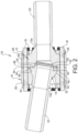
Figure 1 is a perspective cross-sectional view of a misalignment flange according to the principles of the present disclosure; and -
Figure 2 is a cross-sectional view of the misalignment flange shown inFigure 1 . - Corresponding reference numerals indicate corresponding parts throughout the several views of the drawings.
- Example embodiments will now be described more fully with reference to the accompanying drawings.
- Example embodiments are provided so that this disclosure will be thorough, and will fully convey the scope to those who are skilled in the art. Numerous specific details are set forth such as examples of specific components, devices, and methods, to provide a thorough understanding of embodiments of the present disclosure. It will be apparent to those skilled in the art that specific details need not be employed, that example embodiments may be embodied in many different forms and that neither should be construed to limit the scope of the disclosure. In some example embodiments, well-known processes, well-known device structures, and well-known technologies are not described in detail.
- The terminology used herein is for the purpose of describing particular example embodiments only and is not intended to be limiting. As used herein, the singular forms "a," "an," and "the" may be intended to include the plural forms as well, unless the context clearly indicates otherwise. The terms "comprises," "comprising," "including," and "having," are inclusive and therefore specify the presence of stated features, integers, steps, operations, elements, and/or components, but do not preclude the presence or addition of one or more other features, integers, steps, operations, elements, components, and/or groups thereof. The method steps, processes, and operations described herein are not to be construed as necessarily requiring their performance in the particular order discussed or illustrated, unless specifically identified as an order of performance. It is also to be understood that additional or alternative steps may be employed.
- When an element or layer is referred to as being "on," "engaged to," "connected to," or "coupled to" another element or layer, it may be directly on, engaged, connected or coupled to the other element or layer, or intervening elements or layers may be present. In contrast, when an element is referred to as being "directly on," "directly engaged to," "directly connected to," or "directly coupled to" another element or layer, there may be no intervening elements or layers present. Other words used to describe the relationship between elements should be interpreted in a like fashion (e.g., "between" versus "directly between," "adjacent" versus "directly adjacent," etc.). As used herein, the term "and/or" includes any and all combinations of one or more of the associated listed items.
- With reference to
Figures 1 and2 , themisalignment flange 10 according to the invention will now be described. Themisalignment flange 10 includes asocket member 12, aball member 14, aretainer member 16 and a plurality offasteners 18. Afirst pipe 20 can be welded or otherwise connected to aweld flange 12a of thesocket member 12 and asecond pipe 22 can be welded or otherwise connected to aweld flange 14a of theball member 14. -
Socket member 12 includes a first substantially sphericalinternal surface 24 having a first diameter. Thesocket member 12 further includes afirst mounting flange 26 having a plurality ofapertures 28 for receivingfasteners 18. Theretainer member 16 includes asecond mounting flange 30 having a plurality ofapertures 32 for receiving thefasteners 18 which mount thesocket member 12 and theretainer member 16 together. Alternatively, the apertures and fasteners can be eliminated and thesocket member 12 andretainer member 16 can be clamped together or otherwise secured together. Thesocket member 12 includes afirst face surface 34 surrounding the first substantially sphericalinternal surface 24, with the first face having arecessed channel 36 disposed therein. - The
retainer member 16 has a second substantially sphericalinternal surface 38 having a second diameter larger than the first diameter. - The
ball member 14 has a first substantially sphericalexternal surface 40 for engaging the first substantially sphericalinternal surface 24 of thesocket member 12. Theball member 14 has a second substantially sphericalexternal surface 42 for engaging the second substantially sphericalinternal surface 38 of theretainer member 16. The second substantially sphericalexternal surface 42 includes an axially protrudingportion 44 with aradial undercut 46. Theball member 14 is adjustably pivotable relative to thesocket member 12 andretainer member 16 to account for misalignment between thefirst pipe 20 and thesecond pipe 22. The axially protrudingportion 44 can be received in therecessed channel 36. The first substantially spherical external surface includes ametal seal ring 50 at a distal end thereof. The first substantially sphericalinternal surface 24 includes a recessedseal ring 52 engaging the first substantially sphericalexternal surface 40. - The double ball design of the
misalignment flange 10 gives the ability to keep the hydrostatic end load low while also having the increased load capacity. By placing the metal-to-metal seal ring 50 at the end point of the smallerinner bowl profile 40 allows the misalignment flange to maintain a smaller seal ring size. This, in turn, allows for a reduced hydrostatic end load. This also allows a significant reduction in raw material size. By including the largerouter ball profile 42, the misalignment flange also maintains a large load capacity with a large bearing surface and, as a result, a higher bending moment capacity without affecting the seal ring size. In addition, the largerouter ball 42 has an overlap at the front end that, at maximum misalignment, increases its load capacity. A comparative single ball design would have a far higher hydrostatic end load at the same pressure capacity expectation and, as a result, the overall package of the double-ball design can be greatly reduced, providing a significant weight and cost savings. - The use of the
misalignment flange 10 allows subsea installations to be carried out quicker, thus reducing the cost of the overall operation. One ormore misalignment flange 10 can be used as part of a jumper system to give the installation contractors an element of adjustment while eliminating the requirement for jumper flexible bends. This will reduce the requirement of costly, complex and time-consuming metrology measurements prior to final system installation. Additional uses for themisalignment flange 10 is for subsea pipeline installations. Often the actual length of pipe in the exact final location of equipment is unknown right up until the end of an installation program. With the use of themisalignment flange 10, redundancy can be added into the system and final adjustment can be completed prior to installation making the installation quicker and more cost-effective. - The foregoing description of the embodiments has been provided for purposes of illustration and description. It is not intended to be exhaustive or to limit the disclosure. Individual elements or features of a particular embodiment are generally not limited to that particular embodiment, but, where applicable, are interchangeable and can be used in a selected embodiment, even if not specifically shown or described. The same may also be varied in many ways. Such variations are not to be regarded as a departure from the disclosure, and all such modifications are intended to be included within the scope of the invention as long as they fall within the scope of the claims.
Claims (4)
- A pipeline misalignment flange (10), comprising:a socket member (12) having a first substantially spherical internal surface (24) having a first diameter,a retainer member (16) having a second substantially spherical internal surface (38) having a second diameter larger than the first diameter, the socket member (12) and the retainer member (16) being fastened together; anda ball member (14) having a first substantially spherical external surface (40) for engaging the socket member (12) and having a diameter approximately equal to the first diameter and a second substantially spherical external surface (42) for engaging the retainer member (16) and having a diameter approximately equal to the second diameter,the socket member (12) having a first face (34) surrounding the first substantially spherical internal surface (24), the first face (34) having a recessed channel (36),the second substantially spherical external surface (42) including an axially protruding portion (44) with an undercut (46), the ball member (14) being pivotable relative to the socket member (12) such that the axially protruding portion (44) of the second substantially spherical external surface (42) is received in the recessed channel (36), andthe socket member (12) and the retainer member (16) each include a mounting flange (26, 30) having a plurality of apertures (28) for receiving fasteners (18) for securing the socket member (12) and the retainer member (16) together, andcharacterized in that,the first substantially spherical external surface (40) of the ball member (14) includes a metal seal ring (50) at a distal end thereof, wherein the first substantially spherical internal surface (24) includes a recessed seal ring (52) therein,at a maximum misalignment between the ball member (14) and the socket member (12) one side of the axially protruding portion (44) of the ball member (14) provides a complete surface contact with the recessed channel (36).
- The pipeline misalignment flange according to claim 1, wherein the first substantially spherical external surface (40) is at a distal end of the ball member (14).
- The pipeline misalignment flange according to claim 1, further comprising a first pipe (20) welded to a weld flange (12a) of the socket member (12).
- The pipeline misalignment flange according to claim 3, further comprising a second pipe (22) welded to a weld flange (14a) of the ball member (14).
Applications Claiming Priority (1)
| Application Number | Priority Date | Filing Date | Title |
|---|---|---|---|
| US15/978,293 US10627028B2 (en) | 2018-05-14 | 2018-05-14 | Misalignment flange for pipeline installations |
Publications (3)
| Publication Number | Publication Date |
|---|---|
| EP3569909A2 EP3569909A2 (en) | 2019-11-20 |
| EP3569909A3 EP3569909A3 (en) | 2020-02-19 |
| EP3569909B1 true EP3569909B1 (en) | 2023-11-29 |
Family
ID=66105155
Family Applications (1)
| Application Number | Title | Priority Date | Filing Date |
|---|---|---|---|
| EP19168590.8A Active EP3569909B1 (en) | 2018-05-14 | 2019-04-11 | Misalignment flange for pipeline installations |
Country Status (5)
| Country | Link |
|---|---|
| US (1) | US10627028B2 (en) |
| EP (1) | EP3569909B1 (en) |
| AU (1) | AU2019202895B2 (en) |
| CA (1) | CA3038364C (en) |
| DK (1) | DK3569909T3 (en) |
Families Citing this family (1)
| Publication number | Priority date | Publication date | Assignee | Title |
|---|---|---|---|---|
| NL2026033B1 (en) | 2020-07-09 | 2022-03-11 | Wavin Bv | Pivot joints, kits of parts for assembling pivot joints, manhole bases, manholes, water transport systems, and methods of assembling water transport systems |
Family Cites Families (28)
| Publication number | Priority date | Publication date | Assignee | Title |
|---|---|---|---|---|
| US872121A (en) * | 1907-07-27 | 1907-11-26 | Greenlaw Mfg Co | Flexible pipe-joint. |
| US939908A (en) * | 1908-01-23 | 1909-11-09 | Greenlaw Mfg Co | Flexible pipe-joint. |
| US979513A (en) * | 1909-03-24 | 1910-12-27 | Johann Koenig | Flexible pipe-joint. |
| US1888026A (en) | 1925-03-19 | 1932-11-15 | Ralph E Chapman | Balanced joint |
| US2117152A (en) * | 1935-06-26 | 1938-05-10 | Crosti Pietro | Pipe joint |
| US2369849A (en) * | 1943-05-04 | 1945-02-20 | Chiksan Tool Company | Joint for electrical conductors |
| US3292955A (en) * | 1964-02-17 | 1966-12-20 | Anchor Coupling Co Inc | Adjustable pressure line coupling |
| US3454288A (en) | 1967-12-22 | 1969-07-08 | Joseph J Mancusi Jr | Pressure-balanced swivel pipe coupling |
| DE1945523A1 (en) * | 1969-09-09 | 1971-03-11 | Martin Herter | Ball joint pipe connection |
| GB1332902A (en) * | 1970-09-04 | 1973-10-10 | Peress J S | Flexible joint |
| US3754779A (en) * | 1970-09-04 | 1973-08-28 | J Peress | Flexible joints |
| US3746372A (en) * | 1971-05-27 | 1973-07-17 | Vetco Offshore Ind Inc | Flexible pipe joints |
| NL7704152A (en) * | 1977-04-15 | 1978-10-17 | Kreber Maschf Bv | BALL HINGE COUPLING FOR TWO TUBE ENDS. |
| GB1596794A (en) | 1977-07-06 | 1981-08-26 | Shotbolt K | Pipe connectors |
| US4850616A (en) * | 1988-02-19 | 1989-07-25 | Westinghouse Electric Corp. | Flexible joint capable of use in the O'Connor combustor coaxial piping |
| US4840409A (en) | 1988-05-05 | 1989-06-20 | Taper-Lok Corporation | Swivel flow line connector |
| US4840410A (en) * | 1988-05-05 | 1989-06-20 | Welkey Joseph J | Apparatus for making a swiveled flow line connection |
| US5160176A (en) | 1991-11-18 | 1992-11-03 | Stanley Aviation Corporation | Metal seal ball joint coupling assembly |
| DE9207970U1 (en) | 1992-06-13 | 1992-09-03 | Klauck, Manfred, 6610 Lebach | Device for detachable and pressure-tight connection of high-pressure pipes |
| US5368342A (en) | 1992-08-07 | 1994-11-29 | Reflange, Inc. | Misalignment flange and method for use |
| DE29716930U1 (en) | 1997-09-06 | 1997-12-04 | Hesseln, Frank, 45659 Recklinghausen | Swiveling pipe and hose line connection |
| US5975588A (en) * | 1997-09-06 | 1999-11-02 | Hesseln; Joerg | Turnable pipe and hose connections |
| US6419279B1 (en) | 1999-12-13 | 2002-07-16 | Raymond E. Latham | Threaded retainer rings for use in pipe flange connections |
| US7503590B2 (en) * | 2005-08-15 | 2009-03-17 | Eaton Corporation | Fluid line assembly |
| US7717473B1 (en) * | 2007-02-15 | 2010-05-18 | Parker-Hannifin Corporation | Dual walled transfer tube |
| NL2001851C2 (en) | 2008-07-23 | 2010-01-26 | Ihc Holland Ie Bv | Hinge for pressure pipe. |
| JP5394206B2 (en) * | 2009-11-20 | 2014-01-22 | 三桜工業株式会社 | Piping fastening structure |
| DE102016221278A1 (en) * | 2016-10-28 | 2018-05-03 | PFW Aerospace GmbH | Device for connecting pipe ends |
-
2018
- 2018-05-14 US US15/978,293 patent/US10627028B2/en active Active
-
2019
- 2019-03-29 CA CA3038364A patent/CA3038364C/en active Active
- 2019-04-11 EP EP19168590.8A patent/EP3569909B1/en active Active
- 2019-04-11 DK DK19168590.8T patent/DK3569909T3/en active
- 2019-04-24 AU AU2019202895A patent/AU2019202895B2/en active Active
Also Published As
| Publication number | Publication date |
|---|---|
| AU2019202895A1 (en) | 2019-11-28 |
| EP3569909A3 (en) | 2020-02-19 |
| DK3569909T3 (en) | 2024-02-19 |
| US10627028B2 (en) | 2020-04-21 |
| CA3038364C (en) | 2021-10-26 |
| EP3569909A2 (en) | 2019-11-20 |
| AU2019202895B2 (en) | 2020-05-21 |
| US20190346076A1 (en) | 2019-11-14 |
| CA3038364A1 (en) | 2019-11-14 |
Similar Documents
| Publication | Publication Date | Title |
|---|---|---|
| US7530604B2 (en) | Non-serviceable fluid coupling | |
| EP2438416B1 (en) | Pressure transmitter for use in industrial process control system | |
| EP4073412B1 (en) | Ball joint seal | |
| EP3408573B1 (en) | Combination comprising a coupling and a pipe element having wedging groove | |
| US20230167930A1 (en) | Connector for pipes | |
| GB2464672A (en) | A pipe joint wherein overlapping pipes are connected by inserting a wire between aligned grooves | |
| CA2916044A1 (en) | Joint for high-pressure pipes and joint structure | |
| US6059323A (en) | Expansion unit for piping adjustment | |
| AU2019202895B2 (en) | Misalignment flange for pipeline installations | |
| JP2022179753A (en) | Pipe joint assembling method | |
| US20110254266A1 (en) | Self-restraining system for belled pipe | |
| US20170107770A1 (en) | Interface | |
| US4629220A (en) | Method and apparatus for quick-coupling connecting nipple for plastic pipe | |
| US20080029966A1 (en) | Seal assembly | |
| US7694405B2 (en) | Method for coupling a conduit to a fitting | |
| AU2020250258B2 (en) | Dual barrier seal | |
| US6802540B2 (en) | Method and apparatus for coupling a conduit to a fitting | |
| US9765927B2 (en) | Flange fitting | |
| AU2022329471A1 (en) | Pipe connectors | |
| US8944472B2 (en) | Conduit joint and seal ring | |
| US4673198A (en) | Sewer pipes | |
| EP3431833B1 (en) | Metal to metal wedge ring seal | |
| US10598305B2 (en) | Flexible pipe joint | |
| WO2025021319A1 (en) | Flexible pipe sealing | |
| RU120185U1 (en) | PIPELINE CONNECTION |
Legal Events
| Date | Code | Title | Description |
|---|---|---|---|
| PUAI | Public reference made under article 153(3) epc to a published international application that has entered the european phase |
Free format text: ORIGINAL CODE: 0009012 |
|
| STAA | Information on the status of an ep patent application or granted ep patent |
Free format text: STATUS: THE APPLICATION HAS BEEN PUBLISHED |
|
| AK | Designated contracting states |
Kind code of ref document: A2 Designated state(s): AL AT BE BG CH CY CZ DE DK EE ES FI FR GB GR HR HU IE IS IT LI LT LU LV MC MK MT NL NO PL PT RO RS SE SI SK SM TR |
|
| AX | Request for extension of the european patent |
Extension state: BA ME |
|
| PUAL | Search report despatched |
Free format text: ORIGINAL CODE: 0009013 |
|
| AK | Designated contracting states |
Kind code of ref document: A3 Designated state(s): AL AT BE BG CH CY CZ DE DK EE ES FI FR GB GR HR HU IE IS IT LI LT LU LV MC MK MT NL NO PL PT RO RS SE SI SK SM TR |
|
| AX | Request for extension of the european patent |
Extension state: BA ME |
|
| RIC1 | Information provided on ipc code assigned before grant |
Ipc: F16L 27/053 20060101ALI20200113BHEP Ipc: F16L 27/047 20060101AFI20200113BHEP |
|
| STAA | Information on the status of an ep patent application or granted ep patent |
Free format text: STATUS: REQUEST FOR EXAMINATION WAS MADE |
|
| 17P | Request for examination filed |
Effective date: 20200522 |
|
| RBV | Designated contracting states (corrected) |
Designated state(s): AL AT BE BG CH CY CZ DE DK EE ES FI FR GB GR HR HU IE IS IT LI LT LU LV MC MK MT NL NO PL PT RO RS SE SI SK SM TR |
|
| STAA | Information on the status of an ep patent application or granted ep patent |
Free format text: STATUS: EXAMINATION IS IN PROGRESS |
|
| 17Q | First examination report despatched |
Effective date: 20210218 |
|
| GRAP | Despatch of communication of intention to grant a patent |
Free format text: ORIGINAL CODE: EPIDOSNIGR1 |
|
| STAA | Information on the status of an ep patent application or granted ep patent |
Free format text: STATUS: GRANT OF PATENT IS INTENDED |
|
| INTG | Intention to grant announced |
Effective date: 20230710 |
|
| GRAS | Grant fee paid |
Free format text: ORIGINAL CODE: EPIDOSNIGR3 |
|
| GRAA | (expected) grant |
Free format text: ORIGINAL CODE: 0009210 |
|
| STAA | Information on the status of an ep patent application or granted ep patent |
Free format text: STATUS: THE PATENT HAS BEEN GRANTED |
|
| AK | Designated contracting states |
Kind code of ref document: B1 Designated state(s): AL AT BE BG CH CY CZ DE DK EE ES FI FR GB GR HR HU IE IS IT LI LT LU LV MC MK MT NL NO PL PT RO RS SE SI SK SM TR |
|
| REG | Reference to a national code |
Ref country code: GB Ref legal event code: FG4D |
|
| REG | Reference to a national code |
Ref country code: CH Ref legal event code: EP |
|
| REG | Reference to a national code |
Ref country code: DE Ref legal event code: R096 Ref document number: 602019042196 Country of ref document: DE |
|
| REG | Reference to a national code |
Ref country code: IE Ref legal event code: FG4D |
|
| REG | Reference to a national code |
Ref country code: DK Ref legal event code: T3 Effective date: 20240216 |
|
| REG | Reference to a national code |
Ref country code: DE Ref legal event code: R081 Ref document number: 602019042196 Country of ref document: DE Owner name: FREUDENBERG FLOW TECHNOLOGIES LLC (N.D.GES.D.S, US Free format text: FORMER OWNER: FREUDENBERG OIL & GAS, LLC, HOUSTON, TX, US |
|
| REG | Reference to a national code |
Ref country code: LT Ref legal event code: MG9D |
|
| REG | Reference to a national code |
Ref country code: NL Ref legal event code: MP Effective date: 20231129 |
|
| PG25 | Lapsed in a contracting state [announced via postgrant information from national office to epo] |
Ref country code: GR Free format text: LAPSE BECAUSE OF FAILURE TO SUBMIT A TRANSLATION OF THE DESCRIPTION OR TO PAY THE FEE WITHIN THE PRESCRIBED TIME-LIMIT Effective date: 20240301 |
|
| PG25 | Lapsed in a contracting state [announced via postgrant information from national office to epo] |
Ref country code: IS Free format text: LAPSE BECAUSE OF FAILURE TO SUBMIT A TRANSLATION OF THE DESCRIPTION OR TO PAY THE FEE WITHIN THE PRESCRIBED TIME-LIMIT Effective date: 20240329 |
|
| PG25 | Lapsed in a contracting state [announced via postgrant information from national office to epo] |
Ref country code: LT Free format text: LAPSE BECAUSE OF FAILURE TO SUBMIT A TRANSLATION OF THE DESCRIPTION OR TO PAY THE FEE WITHIN THE PRESCRIBED TIME-LIMIT Effective date: 20231129 |
|
| PG25 | Lapsed in a contracting state [announced via postgrant information from national office to epo] |
Ref country code: ES Free format text: LAPSE BECAUSE OF FAILURE TO SUBMIT A TRANSLATION OF THE DESCRIPTION OR TO PAY THE FEE WITHIN THE PRESCRIBED TIME-LIMIT Effective date: 20231129 |
|
| PG25 | Lapsed in a contracting state [announced via postgrant information from national office to epo] |
Ref country code: LT Free format text: LAPSE BECAUSE OF FAILURE TO SUBMIT A TRANSLATION OF THE DESCRIPTION OR TO PAY THE FEE WITHIN THE PRESCRIBED TIME-LIMIT Effective date: 20231129 Ref country code: IS Free format text: LAPSE BECAUSE OF FAILURE TO SUBMIT A TRANSLATION OF THE DESCRIPTION OR TO PAY THE FEE WITHIN THE PRESCRIBED TIME-LIMIT Effective date: 20240329 Ref country code: GR Free format text: LAPSE BECAUSE OF FAILURE TO SUBMIT A TRANSLATION OF THE DESCRIPTION OR TO PAY THE FEE WITHIN THE PRESCRIBED TIME-LIMIT Effective date: 20240301 Ref country code: ES Free format text: LAPSE BECAUSE OF FAILURE TO SUBMIT A TRANSLATION OF THE DESCRIPTION OR TO PAY THE FEE WITHIN THE PRESCRIBED TIME-LIMIT Effective date: 20231129 Ref country code: BG Free format text: LAPSE BECAUSE OF FAILURE TO SUBMIT A TRANSLATION OF THE DESCRIPTION OR TO PAY THE FEE WITHIN THE PRESCRIBED TIME-LIMIT Effective date: 20240229 |
|
| REG | Reference to a national code |
Ref country code: AT Ref legal event code: MK05 Ref document number: 1636459 Country of ref document: AT Kind code of ref document: T Effective date: 20231129 |
|
| PG25 | Lapsed in a contracting state [announced via postgrant information from national office to epo] |
Ref country code: NL Free format text: LAPSE BECAUSE OF FAILURE TO SUBMIT A TRANSLATION OF THE DESCRIPTION OR TO PAY THE FEE WITHIN THE PRESCRIBED TIME-LIMIT Effective date: 20231129 |
|
| PG25 | Lapsed in a contracting state [announced via postgrant information from national office to epo] |
Ref country code: SE Free format text: LAPSE BECAUSE OF FAILURE TO SUBMIT A TRANSLATION OF THE DESCRIPTION OR TO PAY THE FEE WITHIN THE PRESCRIBED TIME-LIMIT Effective date: 20231129 Ref country code: RS Free format text: LAPSE BECAUSE OF FAILURE TO SUBMIT A TRANSLATION OF THE DESCRIPTION OR TO PAY THE FEE WITHIN THE PRESCRIBED TIME-LIMIT Effective date: 20231129 Ref country code: PL Free format text: LAPSE BECAUSE OF FAILURE TO SUBMIT A TRANSLATION OF THE DESCRIPTION OR TO PAY THE FEE WITHIN THE PRESCRIBED TIME-LIMIT Effective date: 20231129 Ref country code: NL Free format text: LAPSE BECAUSE OF FAILURE TO SUBMIT A TRANSLATION OF THE DESCRIPTION OR TO PAY THE FEE WITHIN THE PRESCRIBED TIME-LIMIT Effective date: 20231129 Ref country code: LV Free format text: LAPSE BECAUSE OF FAILURE TO SUBMIT A TRANSLATION OF THE DESCRIPTION OR TO PAY THE FEE WITHIN THE PRESCRIBED TIME-LIMIT Effective date: 20231129 Ref country code: HR Free format text: LAPSE BECAUSE OF FAILURE TO SUBMIT A TRANSLATION OF THE DESCRIPTION OR TO PAY THE FEE WITHIN THE PRESCRIBED TIME-LIMIT Effective date: 20231129 |
|
| PG25 | Lapsed in a contracting state [announced via postgrant information from national office to epo] |
Ref country code: AT Free format text: LAPSE BECAUSE OF FAILURE TO SUBMIT A TRANSLATION OF THE DESCRIPTION OR TO PAY THE FEE WITHIN THE PRESCRIBED TIME-LIMIT Effective date: 20231129 Ref country code: CZ Free format text: LAPSE BECAUSE OF FAILURE TO SUBMIT A TRANSLATION OF THE DESCRIPTION OR TO PAY THE FEE WITHIN THE PRESCRIBED TIME-LIMIT Effective date: 20231129 |
|
| PG25 | Lapsed in a contracting state [announced via postgrant information from national office to epo] |
Ref country code: SK Free format text: LAPSE BECAUSE OF FAILURE TO SUBMIT A TRANSLATION OF THE DESCRIPTION OR TO PAY THE FEE WITHIN THE PRESCRIBED TIME-LIMIT Effective date: 20231129 |
|
| PG25 | Lapsed in a contracting state [announced via postgrant information from national office to epo] |
Ref country code: SM Free format text: LAPSE BECAUSE OF FAILURE TO SUBMIT A TRANSLATION OF THE DESCRIPTION OR TO PAY THE FEE WITHIN THE PRESCRIBED TIME-LIMIT Effective date: 20231129 Ref country code: SK Free format text: LAPSE BECAUSE OF FAILURE TO SUBMIT A TRANSLATION OF THE DESCRIPTION OR TO PAY THE FEE WITHIN THE PRESCRIBED TIME-LIMIT Effective date: 20231129 Ref country code: RO Free format text: LAPSE BECAUSE OF FAILURE TO SUBMIT A TRANSLATION OF THE DESCRIPTION OR TO PAY THE FEE WITHIN THE PRESCRIBED TIME-LIMIT Effective date: 20231129 Ref country code: IT Free format text: LAPSE BECAUSE OF FAILURE TO SUBMIT A TRANSLATION OF THE DESCRIPTION OR TO PAY THE FEE WITHIN THE PRESCRIBED TIME-LIMIT Effective date: 20231129 Ref country code: EE Free format text: LAPSE BECAUSE OF FAILURE TO SUBMIT A TRANSLATION OF THE DESCRIPTION OR TO PAY THE FEE WITHIN THE PRESCRIBED TIME-LIMIT Effective date: 20231129 Ref country code: CZ Free format text: LAPSE BECAUSE OF FAILURE TO SUBMIT A TRANSLATION OF THE DESCRIPTION OR TO PAY THE FEE WITHIN THE PRESCRIBED TIME-LIMIT Effective date: 20231129 Ref country code: AT Free format text: LAPSE BECAUSE OF FAILURE TO SUBMIT A TRANSLATION OF THE DESCRIPTION OR TO PAY THE FEE WITHIN THE PRESCRIBED TIME-LIMIT Effective date: 20231129 |
|
| PG25 | Lapsed in a contracting state [announced via postgrant information from national office to epo] |
Ref country code: PT Free format text: LAPSE BECAUSE OF FAILURE TO SUBMIT A TRANSLATION OF THE DESCRIPTION OR TO PAY THE FEE WITHIN THE PRESCRIBED TIME-LIMIT Effective date: 20240401 |
|
| PG25 | Lapsed in a contracting state [announced via postgrant information from national office to epo] |
Ref country code: PT Free format text: LAPSE BECAUSE OF FAILURE TO SUBMIT A TRANSLATION OF THE DESCRIPTION OR TO PAY THE FEE WITHIN THE PRESCRIBED TIME-LIMIT Effective date: 20240401 |
|
| REG | Reference to a national code |
Ref country code: DE Ref legal event code: R097 Ref document number: 602019042196 Country of ref document: DE |
|
| PLBE | No opposition filed within time limit |
Free format text: ORIGINAL CODE: 0009261 |
|
| STAA | Information on the status of an ep patent application or granted ep patent |
Free format text: STATUS: NO OPPOSITION FILED WITHIN TIME LIMIT |
|
| PG25 | Lapsed in a contracting state [announced via postgrant information from national office to epo] |
Ref country code: SI Free format text: LAPSE BECAUSE OF FAILURE TO SUBMIT A TRANSLATION OF THE DESCRIPTION OR TO PAY THE FEE WITHIN THE PRESCRIBED TIME-LIMIT Effective date: 20231129 |
|
| PG25 | Lapsed in a contracting state [announced via postgrant information from national office to epo] |
Ref country code: SI Free format text: LAPSE BECAUSE OF FAILURE TO SUBMIT A TRANSLATION OF THE DESCRIPTION OR TO PAY THE FEE WITHIN THE PRESCRIBED TIME-LIMIT Effective date: 20231129 |
|
| 26N | No opposition filed |
Effective date: 20240830 |
|
| PG25 | Lapsed in a contracting state [announced via postgrant information from national office to epo] |
Ref country code: MC Free format text: LAPSE BECAUSE OF FAILURE TO SUBMIT A TRANSLATION OF THE DESCRIPTION OR TO PAY THE FEE WITHIN THE PRESCRIBED TIME-LIMIT Effective date: 20231129 |
|
| PG25 | Lapsed in a contracting state [announced via postgrant information from national office to epo] |
Ref country code: MC Free format text: LAPSE BECAUSE OF FAILURE TO SUBMIT A TRANSLATION OF THE DESCRIPTION OR TO PAY THE FEE WITHIN THE PRESCRIBED TIME-LIMIT Effective date: 20231129 |
|
| REG | Reference to a national code |
Ref country code: CH Ref legal event code: PL |
|
| PG25 | Lapsed in a contracting state [announced via postgrant information from national office to epo] |
Ref country code: LU Free format text: LAPSE BECAUSE OF NON-PAYMENT OF DUE FEES Effective date: 20240411 |
|
| REG | Reference to a national code |
Ref country code: BE Ref legal event code: MM Effective date: 20240430 |
|
| PG25 | Lapsed in a contracting state [announced via postgrant information from national office to epo] |
Ref country code: LU Free format text: LAPSE BECAUSE OF NON-PAYMENT OF DUE FEES Effective date: 20240411 |
|
| PG25 | Lapsed in a contracting state [announced via postgrant information from national office to epo] |
Ref country code: BE Free format text: LAPSE BECAUSE OF NON-PAYMENT OF DUE FEES Effective date: 20240430 |
|
| PG25 | Lapsed in a contracting state [announced via postgrant information from national office to epo] |
Ref country code: BE Free format text: LAPSE BECAUSE OF NON-PAYMENT OF DUE FEES Effective date: 20240430 Ref country code: CH Free format text: LAPSE BECAUSE OF NON-PAYMENT OF DUE FEES Effective date: 20240430 |
|
| PG25 | Lapsed in a contracting state [announced via postgrant information from national office to epo] |
Ref country code: IE Free format text: LAPSE BECAUSE OF NON-PAYMENT OF DUE FEES Effective date: 20240411 |
|
| PGFP | Annual fee paid to national office [announced via postgrant information from national office to epo] |
Ref country code: DE Payment date: 20250430 Year of fee payment: 7 |
|
| PGFP | Annual fee paid to national office [announced via postgrant information from national office to epo] |
Ref country code: DK Payment date: 20250429 Year of fee payment: 7 Ref country code: GB Payment date: 20250426 Year of fee payment: 7 |
|
| PGFP | Annual fee paid to national office [announced via postgrant information from national office to epo] |
Ref country code: NO Payment date: 20250428 Year of fee payment: 7 |
|
| PGFP | Annual fee paid to national office [announced via postgrant information from national office to epo] |
Ref country code: FR Payment date: 20250426 Year of fee payment: 7 |
|
| PG25 | Lapsed in a contracting state [announced via postgrant information from national office to epo] |
Ref country code: CY Free format text: LAPSE BECAUSE OF FAILURE TO SUBMIT A TRANSLATION OF THE DESCRIPTION OR TO PAY THE FEE WITHIN THE PRESCRIBED TIME-LIMIT; INVALID AB INITIO Effective date: 20190411 |
|
| PG25 | Lapsed in a contracting state [announced via postgrant information from national office to epo] |
Ref country code: HU Free format text: LAPSE BECAUSE OF FAILURE TO SUBMIT A TRANSLATION OF THE DESCRIPTION OR TO PAY THE FEE WITHIN THE PRESCRIBED TIME-LIMIT; INVALID AB INITIO Effective date: 20190411 |
|
| PG25 | Lapsed in a contracting state [announced via postgrant information from national office to epo] |
Ref country code: FI Free format text: LAPSE BECAUSE OF FAILURE TO SUBMIT A TRANSLATION OF THE DESCRIPTION OR TO PAY THE FEE WITHIN THE PRESCRIBED TIME-LIMIT Effective date: 20231129 |