EP3569896A1 - A transmission - Google Patents
A transmission Download PDFInfo
- Publication number
- EP3569896A1 EP3569896A1 EP18172159.8A EP18172159A EP3569896A1 EP 3569896 A1 EP3569896 A1 EP 3569896A1 EP 18172159 A EP18172159 A EP 18172159A EP 3569896 A1 EP3569896 A1 EP 3569896A1
- Authority
- EP
- European Patent Office
- Prior art keywords
- transmission
- oil
- sensor
- oil channel
- component
- Prior art date
- Legal status (The legal status is an assumption and is not a legal conclusion. Google has not performed a legal analysis and makes no representation as to the accuracy of the status listed.)
- Granted
Links
Images



Classifications
-
- F—MECHANICAL ENGINEERING; LIGHTING; HEATING; WEAPONS; BLASTING
- F16—ENGINEERING ELEMENTS AND UNITS; GENERAL MEASURES FOR PRODUCING AND MAINTAINING EFFECTIVE FUNCTIONING OF MACHINES OR INSTALLATIONS; THERMAL INSULATION IN GENERAL
- F16H—GEARING
- F16H57/00—General details of gearing
- F16H57/04—Features relating to lubrication or cooling or heating
- F16H57/042—Guidance of lubricant
- F16H57/0421—Guidance of lubricant on or within the casing, e.g. shields or baffles for collecting lubricant, tubes, pipes, grooves, channels or the like
- F16H57/0423—Lubricant guiding means mounted or supported on the casing, e.g. shields or baffles for collecting lubricant, tubes or pipes
-
- F—MECHANICAL ENGINEERING; LIGHTING; HEATING; WEAPONS; BLASTING
- F16—ENGINEERING ELEMENTS AND UNITS; GENERAL MEASURES FOR PRODUCING AND MAINTAINING EFFECTIVE FUNCTIONING OF MACHINES OR INSTALLATIONS; THERMAL INSULATION IN GENERAL
- F16H—GEARING
- F16H57/00—General details of gearing
- F16H57/02—Gearboxes; Mounting gearing therein
- F16H2057/02095—Measures for reducing number of parts or components
-
- F—MECHANICAL ENGINEERING; LIGHTING; HEATING; WEAPONS; BLASTING
- F16—ENGINEERING ELEMENTS AND UNITS; GENERAL MEASURES FOR PRODUCING AND MAINTAINING EFFECTIVE FUNCTIONING OF MACHINES OR INSTALLATIONS; THERMAL INSULATION IN GENERAL
- F16H—GEARING
- F16H57/00—General details of gearing
- F16H57/04—Features relating to lubrication or cooling or heating
- F16H57/042—Guidance of lubricant
- F16H57/0421—Guidance of lubricant on or within the casing, e.g. shields or baffles for collecting lubricant, tubes, pipes, grooves, channels or the like
- F16H57/0426—Means for guiding lubricant into an axial channel of a shaft
-
- F—MECHANICAL ENGINEERING; LIGHTING; HEATING; WEAPONS; BLASTING
- F16—ENGINEERING ELEMENTS AND UNITS; GENERAL MEASURES FOR PRODUCING AND MAINTAINING EFFECTIVE FUNCTIONING OF MACHINES OR INSTALLATIONS; THERMAL INSULATION IN GENERAL
- F16H—GEARING
- F16H57/00—General details of gearing
- F16H57/04—Features relating to lubrication or cooling or heating
- F16H57/042—Guidance of lubricant
- F16H57/043—Guidance of lubricant within rotary parts, e.g. axial channels or radial openings in shafts
-
- F—MECHANICAL ENGINEERING; LIGHTING; HEATING; WEAPONS; BLASTING
- F16—ENGINEERING ELEMENTS AND UNITS; GENERAL MEASURES FOR PRODUCING AND MAINTAINING EFFECTIVE FUNCTIONING OF MACHINES OR INSTALLATIONS; THERMAL INSULATION IN GENERAL
- F16H—GEARING
- F16H57/00—General details of gearing
- F16H57/04—Features relating to lubrication or cooling or heating
- F16H57/0467—Elements of gearings to be lubricated, cooled or heated
- F16H57/0469—Bearings or seals
- F16H57/0471—Bearing
-
- F—MECHANICAL ENGINEERING; LIGHTING; HEATING; WEAPONS; BLASTING
- F16—ENGINEERING ELEMENTS AND UNITS; GENERAL MEASURES FOR PRODUCING AND MAINTAINING EFFECTIVE FUNCTIONING OF MACHINES OR INSTALLATIONS; THERMAL INSULATION IN GENERAL
- F16H—GEARING
- F16H57/00—General details of gearing
- F16H57/04—Features relating to lubrication or cooling or heating
- F16H57/0467—Elements of gearings to be lubricated, cooled or heated
- F16H57/0478—Synchromesh devices
Definitions
- the invention relates to a transmission having a bar supporting at least one sensor for measuring an operating parameter of the transmission.
- Vehicle transmissions usually have sensors for measuring operating parameters of the transmissions.
- sensors can be arranged in a housing of the transmission.
- the sensors can be arranged on a bar extending into the inner space of the transmission.
- An objective of the invention is to provide a transmission enabling a reduced number of components and thereby an increased available space inside the transmission and saved costs.
- the objective is achieved by a transmission, wherein the transmission comprises a bar supporting at least one sensor for measuring an operating parameter of the transmission and the sensor bar is provided with an oil channel for transportation of lubrication oil to at least one component of the transmission.
- the invention is based on the insight that by such a transmission, a sensor position for measuring an operating parameter and means for lubrication of a component can be achieved by use of one and the same part.
- the sensor supported by the sensor bar can be any sensor arranged on the sensor bar for measuring for example the speed of a shaft or a gear wheel of the transmission or the position of a gear shifting fork or a sleeve of the transmission.
- the component to be lubricated can be a part of a synchronizer device or a bearing, for instance.
- the oil channel has an inlet arranged in vicinity of a space arranged inside the transmission for containing oil, and a gear wheel of the transmission is arranged for rotating in the oil of the space and drawing oil to the inlet of the oil channel.
- a gear wheel of the transmission is arranged for rotating in the oil of the space and drawing oil to the inlet of the oil channel.
- the sensor bar is arranged to extend in an axial direction across the transmission enabling transportation of oil in the oil channel from a first side of the transmission to said at least one component at a second side of the transmission.
- the component or components to be lubricated can be reached at the same time as several relevant positions along the sensor bar are available for arranging sensors for measuring operating parameters of the transmission.
- the sensor bar has an inclined open chute forming the oil channel for transportation of oil by gravity.
- the oil can easily be brought by a gear wheel into the oil channel and further transportation of the oil in the oil channel can be performed without any additional means, such as a pump or similar.
- an outlet of the oil channel is fluidly connected to the space inside of a tubular shaft of the transmission and said at least one component is arranged on the tubular shaft and fluidly connected to the oil channel via a radially directed through hole of the tubular shaft extending between the component and the space inside of the tubular shaft.
- Fig. 1 is a schematic view showing a transmission 1 having a housing 2, an input shaft 3 and an output shaft 4.
- the transmission 1 has a bar 5 supporting at least one sensor 6a, 6b for measuring an operating parameter of the transmission 1.
- a first sensor 6a and a second sensor 6b are arranged on the sensor bar 5.
- the first sensor 6a is arranged for measuring a parameter related to the input shaft 3
- the second sensor 6b is arranged for measuring a parameter related to the output shaft 4.
- the sensor bar 5 can be arranged between the input shaft 3 and the output shaft 4, though on another level as illustrated.
- the sensor bar 5 is suitably arranged substantially in parallel with the input shaft 3 and the output shaft 4.
- the sensor bar 5 is provided with an oil channel 7 for transportation of lubrication oil to at least one component of the transmission 1.
- the oil channel 7 has an oil inlet 8 and an oil outlet 9.
- the flow of oil along the oil channel 7 is schematically indicated by arrows 10.
- the sensor bar 5 can be arranged to extend in an axial direction across the transmission 1 enabling transportation of oil in the oil channel 7 from a first side 11 of the transmission to said at least one component at a second side 12 of the transmission.
- the sensor bar 5 can be arranged to extend in the axial direction across substantially the entire length of the transmission 1, and the sensor bar 5 is preferably attached to the housing 2 at the first side 11 and/or the second side 12 of the transmission 1.
- the oil channel inlet 8 is suitably arranged in vicinity of a space 13 arranged inside the transmission 1 for containing oil.
- a gear wheel 14 of the transmission 1 can be arranged for rotating in the oil of the space and drawing oil to the inlet 8 of the oil channel 7.
- This space can be an oil sump or any space containing oil to be used for lubrication.
- the gear wheel 14 is a final drive gear of a differential of the transmission 1.
- the gear wheel 14 is splashing oil to be collected and transported by the oil channel 7 of the sensor bar 5.
- the inlet 8 of the oil channel can be constituted by an opening arranged at any position along the sensor bar 5, preferably at an end thereof, the sensor bar could also have an oil channel formed by a sensor bar 5 providing an open chute.
- the sensor bar can have a U-shaped or V-shaped cross-section with the opening directed upwards for forming the oil channel 7 and accommodating oil therein. In such a case oil could be brought into the channel along the entire opening of the sensor bar.
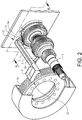
- Fig. 2 shows the sensor bar 5 and the input shaft 3 more in detail. In this perspective view, only some components of the transmission are shown. Other components are omitted for illustration purposes only.
- the sensor bar 5 has an inclined open chute forming the oil channel 7 for transportation of oil by gravity.
- the sensor bar 5 has a cross section with a flat bottom portion 20 and a side wall portion 21a, 21b arranged at each side of the bottom portion 20 which portions form the oil channel 7.
- the oil is brought into the oil channel by means of a gear wheel 14.
- the sensor bar 5 is further inclined relative to a horizontal such that the oil is flowing by gravity from the inlet 8 to the outlet 9 at the other end 23 of the sensor bar 5.
- a first set of sensors 6a can be arranged on the sensor bar 5 for measuring operating parameters related to the input shaft 3.
- a second set of sensors 6b (see Fig. 1 ) can be arranged on the sensor bar 5 for measuring operating parameters related to the output shaft 4.
- the first set of sensors can comprise a speed sensor and a position sensor for measuring a rotation speed of a shaft or a gear wheel and a position of a gear shifting fork or a sleeve, respectively.
- the second set of sensors can comprise a speed sensor and a position sensor for measuring a rotation speed of a shaft or a gear wheel and a position of a gear shifting fork or a sleeve, respectively.
- Fig. 2a shows a cross-section view of the sensor bar and an end of the input shaft 3.
- the outlet 9 of the oil channel 7 is connected to a space 24 inside a shaft, herein exemplified by the input shaft 3.
- Fig. 3 is a cut view of the input shaft 3 illustrated in Fig. 2 .
- the shaft 3 is tubular and the space 24 inside the shaft 3 is fluidly connected with the outlet 9 of the oil channel 7.
- the arrows 10 in Fig. 3 indicate the flow of oil from the oil channel 7 into the shaft 3.
- the components 25 to be lubricated are arranged on the shaft 3 and fluidly connected to the inner space 24 of the shaft 3 and the oil channel 7 via one or more radially directed through holes 26 of the tubular shaft. These through holes extend between the current component 25 and the space 24 of the tubular shaft 3.
- the at least one component to be lubricated can be a synchronizer component, a bearing or any other transmission component where lubrication by oil is required.
Landscapes
- Engineering & Computer Science (AREA)
- General Engineering & Computer Science (AREA)
- Mechanical Engineering (AREA)
- General Details Of Gearings (AREA)
Abstract
Description
- The invention relates to a transmission having a bar supporting at least one sensor for measuring an operating parameter of the transmission.
- Vehicle transmissions usually have sensors for measuring operating parameters of the transmissions. Such sensors can be arranged in a housing of the transmission. For providing sensor positions the sensors can be arranged on a bar extending into the inner space of the transmission.
- There is a lot of components inside a transmission and many components also have to be lubricated by oil for functioning as intended. This makes the transmission relatively complicated and the packing space in the transmission is often very limited.
- An objective of the invention is to provide a transmission enabling a reduced number of components and thereby an increased available space inside the transmission and saved costs.
- The objective is achieved by a transmission, wherein the transmission comprises a bar supporting at least one sensor for measuring an operating parameter of the transmission and the sensor bar is provided with an oil channel for transportation of lubrication oil to at least one component of the transmission.
- The invention is based on the insight that by such a transmission, a sensor position for measuring an operating parameter and means for lubrication of a component can be achieved by use of one and the same part.
- The sensor supported by the sensor bar can be any sensor arranged on the sensor bar for measuring for example the speed of a shaft or a gear wheel of the transmission or the position of a gear shifting fork or a sleeve of the transmission.
- The component to be lubricated can be a part of a synchronizer device or a bearing, for instance.
- According to one embodiment of the transmission, the oil channel has an inlet arranged in vicinity of a space arranged inside the transmission for containing oil, and a gear wheel of the transmission is arranged for rotating in the oil of the space and drawing oil to the inlet of the oil channel. Hereby, no additional part is needed for providing the oil to the oil channel, since an existing gear wheel, such as for example a final drive gear of a differential, can be used for transportation of the oil to the oil channel.
- According to a further embodiment, the sensor bar is arranged to extend in an axial direction across the transmission enabling transportation of oil in the oil channel from a first side of the transmission to said at least one component at a second side of the transmission. Hereby, the component or components to be lubricated can be reached at the same time as several relevant positions along the sensor bar are available for arranging sensors for measuring operating parameters of the transmission.
- According to a further embodiment, the sensor bar has an inclined open chute forming the oil channel for transportation of oil by gravity. Hereby, the oil can easily be brought by a gear wheel into the oil channel and further transportation of the oil in the oil channel can be performed without any additional means, such as a pump or similar.
- According to a further embodiment, an outlet of the oil channel is fluidly connected to the space inside of a tubular shaft of the transmission and said at least one component is arranged on the tubular shaft and fluidly connected to the oil channel via a radially directed through hole of the tubular shaft extending between the component and the space inside of the tubular shaft. Hereby, components arranged on a shaft, such as synchronizer device parts, arranged at various positions, which otherwise could be difficult to reach, can be lubricated by oil from the oil channel by using only one outlet of the oil channel fluidly connected to the space inside of the shaft at one end thereof.
- With reference to the appended drawings, below follows a more detailed description of embodiments of the invention cited as examples.
- In the drawings:
- Fig. 1
- is a schematic view showing a transmission having a sensor bar,
- Fig. 2
- is a perspective view of a shaft and the sensor bar of the transmission in
Fig. 1 , - Fig. 2a
- is a cross-section view of the sensor bar and an end of the shaft in
Fig. 2 , and - Fig. 3
- is a cut view of the shaft in
Fig. 2 . -
Fig. 1 is a schematic view showing atransmission 1 having ahousing 2, aninput shaft 3 and anoutput shaft 4. Thetransmission 1 has abar 5 supporting at least onesensor transmission 1. In the illustrated example embodiment inFig. 1 , afirst sensor 6a and asecond sensor 6b are arranged on thesensor bar 5. Thefirst sensor 6a is arranged for measuring a parameter related to theinput shaft 3 and thesecond sensor 6b is arranged for measuring a parameter related to theoutput shaft 4. Thesensor bar 5 can be arranged between theinput shaft 3 and theoutput shaft 4, though on another level as illustrated. - The
sensor bar 5 is suitably arranged substantially in parallel with theinput shaft 3 and theoutput shaft 4. Thesensor bar 5 is provided with anoil channel 7 for transportation of lubrication oil to at least one component of thetransmission 1. Theoil channel 7 has anoil inlet 8 and anoil outlet 9. The flow of oil along theoil channel 7 is schematically indicated byarrows 10. Thesensor bar 5 can be arranged to extend in an axial direction across thetransmission 1 enabling transportation of oil in theoil channel 7 from afirst side 11 of the transmission to said at least one component at asecond side 12 of the transmission. Thesensor bar 5 can be arranged to extend in the axial direction across substantially the entire length of thetransmission 1, and thesensor bar 5 is preferably attached to thehousing 2 at thefirst side 11 and/or thesecond side 12 of thetransmission 1. - The
oil channel inlet 8 is suitably arranged in vicinity of aspace 13 arranged inside thetransmission 1 for containing oil. Agear wheel 14 of thetransmission 1 can be arranged for rotating in the oil of the space and drawing oil to theinlet 8 of theoil channel 7. This space can be an oil sump or any space containing oil to be used for lubrication. In the illustrated example embodiment, thegear wheel 14 is a final drive gear of a differential of thetransmission 1. When rotating, thegear wheel 14 is splashing oil to be collected and transported by theoil channel 7 of thesensor bar 5. Although theinlet 8 of the oil channel can be constituted by an opening arranged at any position along thesensor bar 5, preferably at an end thereof, the sensor bar could also have an oil channel formed by asensor bar 5 providing an open chute. For example, the sensor bar can have a U-shaped or V-shaped cross-section with the opening directed upwards for forming theoil channel 7 and accommodating oil therein. In such a case oil could be brought into the channel along the entire opening of the sensor bar. -
Fig. 2 shows thesensor bar 5 and theinput shaft 3 more in detail. In this perspective view, only some components of the transmission are shown. Other components are omitted for illustration purposes only. In the example embodiment illustrated inFig. 2 , thesensor bar 5 has an inclined open chute forming theoil channel 7 for transportation of oil by gravity. As also appears from the enlarged view ofFig. 2a , thesensor bar 5 has a cross section with aflat bottom portion 20 and aside wall portion bottom portion 20 which portions form theoil channel 7. In afirst end 22 of thesensor bar 5, the oil is brought into the oil channel by means of agear wheel 14. Thesensor bar 5 is further inclined relative to a horizontal such that the oil is flowing by gravity from theinlet 8 to theoutlet 9 at theother end 23 of thesensor bar 5. - A first set of
sensors 6a can be arranged on thesensor bar 5 for measuring operating parameters related to theinput shaft 3. A second set ofsensors 6b (seeFig. 1 ) can be arranged on thesensor bar 5 for measuring operating parameters related to theoutput shaft 4. The first set of sensors can comprise a speed sensor and a position sensor for measuring a rotation speed of a shaft or a gear wheel and a position of a gear shifting fork or a sleeve, respectively. In the same way, the second set of sensors can comprise a speed sensor and a position sensor for measuring a rotation speed of a shaft or a gear wheel and a position of a gear shifting fork or a sleeve, respectively. - When the oil is reaching the
outlet 9 of theoil channel 7 the oil should be distributed to one or more components to be lubricated by the oil. This is further illustrated inFigs. 2a and3 . -
Fig. 2a shows a cross-section view of the sensor bar and an end of theinput shaft 3. Theoutlet 9 of theoil channel 7 is connected to aspace 24 inside a shaft, herein exemplified by theinput shaft 3. -
Fig. 3 is a cut view of theinput shaft 3 illustrated inFig. 2 . Theshaft 3 is tubular and thespace 24 inside theshaft 3 is fluidly connected with theoutlet 9 of theoil channel 7. Thearrows 10 inFig. 3 indicate the flow of oil from theoil channel 7 into theshaft 3. Further, thecomponents 25 to be lubricated are arranged on theshaft 3 and fluidly connected to theinner space 24 of theshaft 3 and theoil channel 7 via one or more radially directed throughholes 26 of the tubular shaft. These through holes extend between thecurrent component 25 and thespace 24 of thetubular shaft 3. - The at least one component to be lubricated can be a synchronizer component, a bearing or any other transmission component where lubrication by oil is required.
- It is to be understood that the present invention is not limited to the embodiments described above and illustrated in the drawings; rather, the skilled person will recognize that many changes and modifications may be made within the scope of the appended claims.
Claims (12)
- A transmission (1) comprising a bar (5) supporting at least one sensor (6a, 6b) for measuring an operating parameter of the transmission, characterized in that the sensor bar (5) is provided with an oil channel (7) for transportation of lubrication oil to at least one component (25) of the transmission (1).
- A transmission according to claim 1, characterized in that the oil channel (7) has an inlet (8) arranged in vicinity of a space (13) arranged inside the transmission (1) for containing oil.
- A transmission according to claim 2, characterized in that a gear wheel (14) of the transmission (1) is arranged for rotating in the oil of the space (13) and drawing oil to the inlet (8) of the oil channel (7).
- A transmission according to claim 3, characterized in that said gearwheel (14) is a final drive gear of a differential of the transmission (1).
- A transmission according to any preceding claim, characterized in that the sensor bar (5) is arranged to extend in an axial direction across the transmission enabling transportation of oil in the oil channel (7) from a first side (11) of the transmission to said at least one component (25) at a second side (12) of the transmission.
- A transmission according to any preceding claim, characterized in that the sensor bar (5) has an inclined open chute forming the oil channel (7) for transportation of oil by gravity.
- A transmission according to any preceding claim, characterized in that an outlet (9) of the oil channel (7) is fluidly connected to a space (24) inside of a tubular shaft (3) of the transmission (1), and said at least one component (25) is arranged on the tubular shaft (3) and fluidly connected to the oil channel (7) via a radially directed through hole (26) of the tubular shaft (3) extending between the component (25) and the space (24) inside of the tubular shaft (3).
- A transmission according to any preceding claim, characterized in that said at least one component (25) is a part of a synchronizer device.
- A transmission according to any preceding claim, characterized in that said at least one component (25) is a bearing.
- A transmission according to any preceding claim, characterized in that said at least one sensor (6a, 6b) is a speed and/or position sensor.
- A transmission according to claim 10, characterized in that said at least one sensor (6a, 6b) is arranged for measuring the speed of a shaft or a gear wheel of the transmission (1).
- A transmission according to claim 10, characterized in that said at least one sensor (6a, 6b) is arranged for measuring the position of a gear shifting fork or a sleeve of the transmission (1).
Priority Applications (4)
| Application Number | Priority Date | Filing Date | Title |
|---|---|---|---|
| EP18172159.8A EP3569896B1 (en) | 2018-05-14 | 2018-05-14 | A transmission |
| PCT/CN2019/084772 WO2019218863A1 (en) | 2018-05-14 | 2019-04-28 | A transmission |
| CN201980031291.1A CN112105846B (en) | 2018-05-14 | 2019-04-28 | transmission |
| US17/092,432 US11486486B2 (en) | 2018-05-14 | 2020-11-09 | Sensor bar with oil channel in a transmission |
Applications Claiming Priority (1)
| Application Number | Priority Date | Filing Date | Title |
|---|---|---|---|
| EP18172159.8A EP3569896B1 (en) | 2018-05-14 | 2018-05-14 | A transmission |
Publications (2)
| Publication Number | Publication Date |
|---|---|
| EP3569896A1 true EP3569896A1 (en) | 2019-11-20 |
| EP3569896B1 EP3569896B1 (en) | 2021-08-11 |
Family
ID=62165479
Family Applications (1)
| Application Number | Title | Priority Date | Filing Date |
|---|---|---|---|
| EP18172159.8A Active EP3569896B1 (en) | 2018-05-14 | 2018-05-14 | A transmission |
Country Status (4)
| Country | Link |
|---|---|
| US (1) | US11486486B2 (en) |
| EP (1) | EP3569896B1 (en) |
| CN (1) | CN112105846B (en) |
| WO (1) | WO2019218863A1 (en) |
Cited By (1)
| Publication number | Priority date | Publication date | Assignee | Title |
|---|---|---|---|---|
| FR3167708A1 (en) * | 2024-10-21 | 2026-04-24 | Ampere Sas | Electric powertrain and position sensor |
Families Citing this family (7)
| Publication number | Priority date | Publication date | Assignee | Title |
|---|---|---|---|---|
| JP7671158B2 (en) * | 2021-03-08 | 2025-05-01 | ニデック株式会社 | Transmission mechanism and drive unit |
| WO2022196320A1 (en) * | 2021-03-15 | 2022-09-22 | ジヤトコ株式会社 | Component |
| DE102021213489A1 (en) * | 2021-11-30 | 2023-06-01 | Robert Bosch Gesellschaft mit beschränkter Haftung | Oil duct part for installation in a gearbox |
| DE102021213485A1 (en) * | 2021-11-30 | 2023-06-01 | Robert Bosch Gesellschaft mit beschränkter Haftung | Transmission with an oil duct part |
| DE102021213491A1 (en) | 2021-11-30 | 2023-06-01 | Robert Bosch Gesellschaft mit beschränkter Haftung | Oil duct part for installation in a gearbox and gearbox with an oil duct part |
| JP7713111B2 (en) * | 2022-08-08 | 2025-07-24 | ジヤトコ株式会社 | Power transmission |
| US20250101893A1 (en) * | 2023-09-27 | 2025-03-27 | Honda Motor Co., Ltd. | Lubrication mechanism |
Citations (3)
| Publication number | Priority date | Publication date | Assignee | Title |
|---|---|---|---|---|
| US20080202853A1 (en) * | 2007-02-22 | 2008-08-28 | Aisin Ai Co., Ltd. | Transmission Including Magnetic Sensor Device |
| US20130283955A1 (en) * | 2010-11-26 | 2013-10-31 | Kenichi Araki | Lubricating-oil collection guide tool |
| US20160319932A1 (en) * | 2015-04-29 | 2016-11-03 | Zf Friedrichshafen Ag | Device to Actuate Shifting Elements of a Transmission |
Family Cites Families (19)
| Publication number | Priority date | Publication date | Assignee | Title |
|---|---|---|---|---|
| JP2906023B2 (en) * | 1994-09-07 | 1999-06-14 | 本田技研工業株式会社 | Treading force detection device for bicycle with assist motor |
| JP4220443B2 (en) * | 2004-08-06 | 2009-02-04 | ジヤトコ株式会社 | Cooling structure of actuator for shift control |
| JP4375462B2 (en) * | 2007-08-31 | 2009-12-02 | トヨタ自動車株式会社 | Axial piston pump and power transmission device including the same |
| JP2011007210A (en) * | 2009-06-23 | 2011-01-13 | Aisin Ai Co Ltd | Transmission |
| JP2011007208A (en) * | 2009-06-23 | 2011-01-13 | Aisin Ai Co Ltd | Transmission |
| DE102009052595A1 (en) * | 2009-11-10 | 2011-05-12 | GM Global Technology Operations LLC, Detroit | Lubricating system for a vehicle transmission |
| JP2013185672A (en) * | 2012-03-08 | 2013-09-19 | Honda Motor Co Ltd | Transmission |
| CN103047341B (en) * | 2012-12-19 | 2014-06-11 | 哈尔滨工业大学 | Vibration isolator with pneumatic flotation ball bearing for angular decoupling and magnetic suspension plane for driving and positioning |
| US10238534B2 (en) | 2013-03-07 | 2019-03-26 | Novartis Ag | Systems and processes for eye moisturizing during ocular surgery |
| JP5948491B2 (en) * | 2013-03-19 | 2016-07-06 | ジヤトコ株式会社 | Lubrication flow rate control device and lubrication flow rate control method for automatic transmission |
| JP5966997B2 (en) * | 2013-03-29 | 2016-08-10 | マツダ株式会社 | Transmission lubrication structure |
| EP2801737B1 (en) * | 2013-05-08 | 2016-07-20 | Meritor Technology, LLC | Axle assembly and method of reworking an axle assembly |
| DE102013226394A1 (en) * | 2013-12-18 | 2015-06-18 | Robert Bosch Gmbh | Speed-detecting transmission for a motor vehicle |
| CN105848951B (en) * | 2014-01-08 | 2019-04-19 | Ntn株式会社 | In-wheel motor drive |
| CN205089955U (en) * | 2015-10-28 | 2016-03-16 | 上海汽车变速器有限公司 | Motor transmission lubricating system |
| JP6551219B2 (en) * | 2015-12-24 | 2019-07-31 | アイシン・エィ・ダブリュ株式会社 | Oil receiver and method for manufacturing oil receiver |
| CN106443073A (en) * | 2016-08-26 | 2017-02-22 | 湖南吉盛国际动力传动系统有限公司 | Simple detection device for speed sensor for automatic transmission and detection method |
| CN206190876U (en) * | 2016-08-31 | 2017-05-24 | 黄山皖南机床有限公司 | Gear lubricating device |
| CN207316042U (en) * | 2017-01-23 | 2018-05-04 | 格特拉克(江西)传动系统有限公司 | A kind of transmission input shaft Oil Guide lubricating arrangement |
-
2018
- 2018-05-14 EP EP18172159.8A patent/EP3569896B1/en active Active
-
2019
- 2019-04-28 CN CN201980031291.1A patent/CN112105846B/en active Active
- 2019-04-28 WO PCT/CN2019/084772 patent/WO2019218863A1/en not_active Ceased
-
2020
- 2020-11-09 US US17/092,432 patent/US11486486B2/en active Active
Patent Citations (3)
| Publication number | Priority date | Publication date | Assignee | Title |
|---|---|---|---|---|
| US20080202853A1 (en) * | 2007-02-22 | 2008-08-28 | Aisin Ai Co., Ltd. | Transmission Including Magnetic Sensor Device |
| US20130283955A1 (en) * | 2010-11-26 | 2013-10-31 | Kenichi Araki | Lubricating-oil collection guide tool |
| US20160319932A1 (en) * | 2015-04-29 | 2016-11-03 | Zf Friedrichshafen Ag | Device to Actuate Shifting Elements of a Transmission |
Cited By (2)
| Publication number | Priority date | Publication date | Assignee | Title |
|---|---|---|---|---|
| FR3167708A1 (en) * | 2024-10-21 | 2026-04-24 | Ampere Sas | Electric powertrain and position sensor |
| WO2026087438A1 (en) * | 2024-10-21 | 2026-04-30 | Ampere S.A.S. | Electric powertrain and position sensor |
Also Published As
| Publication number | Publication date |
|---|---|
| US20210054918A1 (en) | 2021-02-25 |
| CN112105846B (en) | 2022-07-15 |
| US11486486B2 (en) | 2022-11-01 |
| EP3569896B1 (en) | 2021-08-11 |
| WO2019218863A1 (en) | 2019-11-21 |
| CN112105846A (en) | 2020-12-18 |
Similar Documents
| Publication | Publication Date | Title |
|---|---|---|
| US11486486B2 (en) | Sensor bar with oil channel in a transmission | |
| US20110214947A1 (en) | Lubrication system for a vehicle transmission | |
| US8671793B2 (en) | Lubrication of a rotatable shaft | |
| US20130316866A1 (en) | Power transmission device | |
| KR20120091066A (en) | Transmission | |
| US8708105B2 (en) | Transmission with splash lubrication system | |
| US20160348781A1 (en) | Gear shroud to passively lubricate gearbox component | |
| JPS6332453Y2 (en) | ||
| CN100595447C (en) | Drives for motor vehicles | |
| CN105202162A (en) | Lubricating structure of transmission | |
| US8550214B2 (en) | Machine having lubricant circuit | |
| JP6622790B2 (en) | Mechanical gear transmission | |
| CN112567156B (en) | Lubrication structure of pump and gear device | |
| JP2012112442A (en) | Lubricating structure of differential gear mechanism in final reduction gear system | |
| JP5410562B2 (en) | Lubricator for power transmission mechanism | |
| JP2010054025A (en) | Lubricating structure for transmission | |
| JP6122825B2 (en) | Balancer device for internal combustion engine | |
| EP0148639B1 (en) | Lubrication arrangement in change-speed gearing assembly | |
| CN108700179B (en) | Hollow shaft lubrication device and transmission case comprising a stationary feed sleeve | |
| JP2016031136A (en) | Lubricating oil supply device | |
| JPH05322008A (en) | Lubricating method for transmission | |
| JP2013024289A (en) | Lubricating device of selective gear type transmission | |
| JP2019090467A (en) | Lubrication structure of power transmission device | |
| JP4234557B2 (en) | Planetary gear set | |
| GB2271161A (en) | Gearbox lubrication |
Legal Events
| Date | Code | Title | Description |
|---|---|---|---|
| PUAI | Public reference made under article 153(3) epc to a published international application that has entered the european phase |
Free format text: ORIGINAL CODE: 0009012 |
|
| STAA | Information on the status of an ep patent application or granted ep patent |
Free format text: STATUS: REQUEST FOR EXAMINATION WAS MADE |
|
| 17P | Request for examination filed |
Effective date: 20180514 |
|
| AK | Designated contracting states |
Kind code of ref document: A1 Designated state(s): AL AT BE BG CH CY CZ DE DK EE ES FI FR GB GR HR HU IE IS IT LI LT LU LV MC MK MT NL NO PL PT RO RS SE SI SK SM TR |
|
| AX | Request for extension of the european patent |
Extension state: BA ME |
|
| STAA | Information on the status of an ep patent application or granted ep patent |
Free format text: STATUS: EXAMINATION IS IN PROGRESS |
|
| 17Q | First examination report despatched |
Effective date: 20200402 |
|
| RIC1 | Information provided on ipc code assigned before grant |
Ipc: F16H 57/02 20120101ALN20210218BHEP Ipc: F16H 57/04 20100101AFI20210218BHEP |
|
| GRAP | Despatch of communication of intention to grant a patent |
Free format text: ORIGINAL CODE: EPIDOSNIGR1 |
|
| STAA | Information on the status of an ep patent application or granted ep patent |
Free format text: STATUS: GRANT OF PATENT IS INTENDED |
|
| INTG | Intention to grant announced |
Effective date: 20210406 |
|
| GRAS | Grant fee paid |
Free format text: ORIGINAL CODE: EPIDOSNIGR3 |
|
| GRAA | (expected) grant |
Free format text: ORIGINAL CODE: 0009210 |
|
| STAA | Information on the status of an ep patent application or granted ep patent |
Free format text: STATUS: THE PATENT HAS BEEN GRANTED |
|
| AK | Designated contracting states |
Kind code of ref document: B1 Designated state(s): AL AT BE BG CH CY CZ DE DK EE ES FI FR GB GR HR HU IE IS IT LI LT LU LV MC MK MT NL NO PL PT RO RS SE SI SK SM TR |
|
| REG | Reference to a national code |
Ref country code: CH Ref legal event code: EP |
|
| REG | Reference to a national code |
Ref country code: DE Ref legal event code: R096 Ref document number: 602018021479 Country of ref document: DE |
|
| REG | Reference to a national code |
Ref country code: IE Ref legal event code: FG4D Ref country code: AT Ref legal event code: REF Ref document number: 1419703 Country of ref document: AT Kind code of ref document: T Effective date: 20210915 |
|
| REG | Reference to a national code |
Ref country code: LT Ref legal event code: MG9D |
|
| REG | Reference to a national code |
Ref country code: NL Ref legal event code: MP Effective date: 20210811 |
|
| REG | Reference to a national code |
Ref country code: AT Ref legal event code: MK05 Ref document number: 1419703 Country of ref document: AT Kind code of ref document: T Effective date: 20210811 |
|
| PG25 | Lapsed in a contracting state [announced via postgrant information from national office to epo] |
Ref country code: PT Free format text: LAPSE BECAUSE OF FAILURE TO SUBMIT A TRANSLATION OF THE DESCRIPTION OR TO PAY THE FEE WITHIN THE PRESCRIBED TIME-LIMIT Effective date: 20211213 Ref country code: NO Free format text: LAPSE BECAUSE OF FAILURE TO SUBMIT A TRANSLATION OF THE DESCRIPTION OR TO PAY THE FEE WITHIN THE PRESCRIBED TIME-LIMIT Effective date: 20211111 Ref country code: LT Free format text: LAPSE BECAUSE OF FAILURE TO SUBMIT A TRANSLATION OF THE DESCRIPTION OR TO PAY THE FEE WITHIN THE PRESCRIBED TIME-LIMIT Effective date: 20210811 Ref country code: AT Free format text: LAPSE BECAUSE OF FAILURE TO SUBMIT A TRANSLATION OF THE DESCRIPTION OR TO PAY THE FEE WITHIN THE PRESCRIBED TIME-LIMIT Effective date: 20210811 Ref country code: BG Free format text: LAPSE BECAUSE OF FAILURE TO SUBMIT A TRANSLATION OF THE DESCRIPTION OR TO PAY THE FEE WITHIN THE PRESCRIBED TIME-LIMIT Effective date: 20211111 Ref country code: SE Free format text: LAPSE BECAUSE OF FAILURE TO SUBMIT A TRANSLATION OF THE DESCRIPTION OR TO PAY THE FEE WITHIN THE PRESCRIBED TIME-LIMIT Effective date: 20210811 Ref country code: RS Free format text: LAPSE BECAUSE OF FAILURE TO SUBMIT A TRANSLATION OF THE DESCRIPTION OR TO PAY THE FEE WITHIN THE PRESCRIBED TIME-LIMIT Effective date: 20210811 Ref country code: HR Free format text: LAPSE BECAUSE OF FAILURE TO SUBMIT A TRANSLATION OF THE DESCRIPTION OR TO PAY THE FEE WITHIN THE PRESCRIBED TIME-LIMIT Effective date: 20210811 Ref country code: FI Free format text: LAPSE BECAUSE OF FAILURE TO SUBMIT A TRANSLATION OF THE DESCRIPTION OR TO PAY THE FEE WITHIN THE PRESCRIBED TIME-LIMIT Effective date: 20210811 Ref country code: ES Free format text: LAPSE BECAUSE OF FAILURE TO SUBMIT A TRANSLATION OF THE DESCRIPTION OR TO PAY THE FEE WITHIN THE PRESCRIBED TIME-LIMIT Effective date: 20210811 |
|
| PG25 | Lapsed in a contracting state [announced via postgrant information from national office to epo] |
Ref country code: PL Free format text: LAPSE BECAUSE OF FAILURE TO SUBMIT A TRANSLATION OF THE DESCRIPTION OR TO PAY THE FEE WITHIN THE PRESCRIBED TIME-LIMIT Effective date: 20210811 Ref country code: LV Free format text: LAPSE BECAUSE OF FAILURE TO SUBMIT A TRANSLATION OF THE DESCRIPTION OR TO PAY THE FEE WITHIN THE PRESCRIBED TIME-LIMIT Effective date: 20210811 |
|
| PG25 | Lapsed in a contracting state [announced via postgrant information from national office to epo] |
Ref country code: NL Free format text: LAPSE BECAUSE OF FAILURE TO SUBMIT A TRANSLATION OF THE DESCRIPTION OR TO PAY THE FEE WITHIN THE PRESCRIBED TIME-LIMIT Effective date: 20210811 |
|
| PG25 | Lapsed in a contracting state [announced via postgrant information from national office to epo] |
Ref country code: DK Free format text: LAPSE BECAUSE OF FAILURE TO SUBMIT A TRANSLATION OF THE DESCRIPTION OR TO PAY THE FEE WITHIN THE PRESCRIBED TIME-LIMIT Effective date: 20210811 |
|
| REG | Reference to a national code |
Ref country code: DE Ref legal event code: R097 Ref document number: 602018021479 Country of ref document: DE |
|
| PG25 | Lapsed in a contracting state [announced via postgrant information from national office to epo] |
Ref country code: SM Free format text: LAPSE BECAUSE OF FAILURE TO SUBMIT A TRANSLATION OF THE DESCRIPTION OR TO PAY THE FEE WITHIN THE PRESCRIBED TIME-LIMIT Effective date: 20210811 Ref country code: SK Free format text: LAPSE BECAUSE OF FAILURE TO SUBMIT A TRANSLATION OF THE DESCRIPTION OR TO PAY THE FEE WITHIN THE PRESCRIBED TIME-LIMIT Effective date: 20210811 Ref country code: RO Free format text: LAPSE BECAUSE OF FAILURE TO SUBMIT A TRANSLATION OF THE DESCRIPTION OR TO PAY THE FEE WITHIN THE PRESCRIBED TIME-LIMIT Effective date: 20210811 Ref country code: EE Free format text: LAPSE BECAUSE OF FAILURE TO SUBMIT A TRANSLATION OF THE DESCRIPTION OR TO PAY THE FEE WITHIN THE PRESCRIBED TIME-LIMIT Effective date: 20210811 Ref country code: CZ Free format text: LAPSE BECAUSE OF FAILURE TO SUBMIT A TRANSLATION OF THE DESCRIPTION OR TO PAY THE FEE WITHIN THE PRESCRIBED TIME-LIMIT Effective date: 20210811 Ref country code: AL Free format text: LAPSE BECAUSE OF FAILURE TO SUBMIT A TRANSLATION OF THE DESCRIPTION OR TO PAY THE FEE WITHIN THE PRESCRIBED TIME-LIMIT Effective date: 20210811 |
|
| PLBE | No opposition filed within time limit |
Free format text: ORIGINAL CODE: 0009261 |
|
| STAA | Information on the status of an ep patent application or granted ep patent |
Free format text: STATUS: NO OPPOSITION FILED WITHIN TIME LIMIT |
|
| 26N | No opposition filed |
Effective date: 20220512 |
|
| PG25 | Lapsed in a contracting state [announced via postgrant information from national office to epo] |
Ref country code: IT Free format text: LAPSE BECAUSE OF FAILURE TO SUBMIT A TRANSLATION OF THE DESCRIPTION OR TO PAY THE FEE WITHIN THE PRESCRIBED TIME-LIMIT Effective date: 20210811 |
|
| PG25 | Lapsed in a contracting state [announced via postgrant information from national office to epo] |
Ref country code: SI Free format text: LAPSE BECAUSE OF FAILURE TO SUBMIT A TRANSLATION OF THE DESCRIPTION OR TO PAY THE FEE WITHIN THE PRESCRIBED TIME-LIMIT Effective date: 20210811 |
|
| REG | Reference to a national code |
Ref country code: CH Ref legal event code: PL |
|
| REG | Reference to a national code |
Ref country code: BE Ref legal event code: MM Effective date: 20220531 |
|
| PG25 | Lapsed in a contracting state [announced via postgrant information from national office to epo] |
Ref country code: MC Free format text: LAPSE BECAUSE OF FAILURE TO SUBMIT A TRANSLATION OF THE DESCRIPTION OR TO PAY THE FEE WITHIN THE PRESCRIBED TIME-LIMIT Effective date: 20210811 Ref country code: LU Free format text: LAPSE BECAUSE OF NON-PAYMENT OF DUE FEES Effective date: 20220514 Ref country code: LI Free format text: LAPSE BECAUSE OF NON-PAYMENT OF DUE FEES Effective date: 20220531 Ref country code: CH Free format text: LAPSE BECAUSE OF NON-PAYMENT OF DUE FEES Effective date: 20220531 |
|
| PG25 | Lapsed in a contracting state [announced via postgrant information from national office to epo] |
Ref country code: IE Free format text: LAPSE BECAUSE OF NON-PAYMENT OF DUE FEES Effective date: 20220514 |
|
| PG25 | Lapsed in a contracting state [announced via postgrant information from national office to epo] |
Ref country code: BE Free format text: LAPSE BECAUSE OF NON-PAYMENT OF DUE FEES Effective date: 20220531 |
|
| PG25 | Lapsed in a contracting state [announced via postgrant information from national office to epo] |
Ref country code: HU Free format text: LAPSE BECAUSE OF FAILURE TO SUBMIT A TRANSLATION OF THE DESCRIPTION OR TO PAY THE FEE WITHIN THE PRESCRIBED TIME-LIMIT; INVALID AB INITIO Effective date: 20180514 |
|
| PG25 | Lapsed in a contracting state [announced via postgrant information from national office to epo] |
Ref country code: MK Free format text: LAPSE BECAUSE OF FAILURE TO SUBMIT A TRANSLATION OF THE DESCRIPTION OR TO PAY THE FEE WITHIN THE PRESCRIBED TIME-LIMIT Effective date: 20210811 Ref country code: CY Free format text: LAPSE BECAUSE OF FAILURE TO SUBMIT A TRANSLATION OF THE DESCRIPTION OR TO PAY THE FEE WITHIN THE PRESCRIBED TIME-LIMIT Effective date: 20210811 |
|
| PG25 | Lapsed in a contracting state [announced via postgrant information from national office to epo] |
Ref country code: MT Free format text: LAPSE BECAUSE OF FAILURE TO SUBMIT A TRANSLATION OF THE DESCRIPTION OR TO PAY THE FEE WITHIN THE PRESCRIBED TIME-LIMIT Effective date: 20210811 |
|
| PG25 | Lapsed in a contracting state [announced via postgrant information from national office to epo] |
Ref country code: GR Free format text: LAPSE BECAUSE OF NON-PAYMENT OF DUE FEES Effective date: 20210811 |
|
| PG25 | Lapsed in a contracting state [announced via postgrant information from national office to epo] |
Ref country code: GR Free format text: LAPSE BECAUSE OF NON-PAYMENT OF DUE FEES Effective date: 20210811 |
|
| PGFP | Annual fee paid to national office [announced via postgrant information from national office to epo] |
Ref country code: DE Payment date: 20250519 Year of fee payment: 8 |
|
| PG25 | Lapsed in a contracting state [announced via postgrant information from national office to epo] |
Ref country code: TR Free format text: LAPSE BECAUSE OF FAILURE TO SUBMIT A TRANSLATION OF THE DESCRIPTION OR TO PAY THE FEE WITHIN THE PRESCRIBED TIME-LIMIT Effective date: 20210811 |
|
| PGFP | Annual fee paid to national office [announced via postgrant information from national office to epo] |
Ref country code: GB Payment date: 20260302 Year of fee payment: 9 |
|
| PGFP | Annual fee paid to national office [announced via postgrant information from national office to epo] |
Ref country code: FR Payment date: 20260303 Year of fee payment: 9 |