EP3569857A1 - Electric ducted fan - Google Patents
Electric ducted fan Download PDFInfo
- Publication number
- EP3569857A1 EP3569857A1 EP19169237.5A EP19169237A EP3569857A1 EP 3569857 A1 EP3569857 A1 EP 3569857A1 EP 19169237 A EP19169237 A EP 19169237A EP 3569857 A1 EP3569857 A1 EP 3569857A1
- Authority
- EP
- European Patent Office
- Prior art keywords
- fan
- diameter
- ratio
- sub
- electric
- Prior art date
- Legal status (The legal status is an assumption and is not a legal conclusion. Google has not performed a legal analysis and makes no representation as to the accuracy of the status listed.)
- Granted
Links
Images


Classifications
-
- F—MECHANICAL ENGINEERING; LIGHTING; HEATING; WEAPONS; BLASTING
- F02—COMBUSTION ENGINES; HOT-GAS OR COMBUSTION-PRODUCT ENGINE PLANTS
- F02C—GAS-TURBINE PLANTS; AIR INTAKES FOR JET-PROPULSION PLANTS; CONTROLLING FUEL SUPPLY IN AIR-BREATHING JET-PROPULSION PLANTS
- F02C7/00—Features, components parts, details or accessories, not provided for in, or of interest apart form groups F02C1/00 - F02C6/00; Air intakes for jet-propulsion plants
- F02C7/36—Power transmission arrangements between the different shafts of the gas turbine plant, or between the gas-turbine plant and the power user
-
- F—MECHANICAL ENGINEERING; LIGHTING; HEATING; WEAPONS; BLASTING
- F02—COMBUSTION ENGINES; HOT-GAS OR COMBUSTION-PRODUCT ENGINE PLANTS
- F02K—JET-PROPULSION PLANTS
- F02K5/00—Plants including an engine, other than a gas turbine, driving a compressor or a ducted fan
-
- F—MECHANICAL ENGINEERING; LIGHTING; HEATING; WEAPONS; BLASTING
- F02—COMBUSTION ENGINES; HOT-GAS OR COMBUSTION-PRODUCT ENGINE PLANTS
- F02K—JET-PROPULSION PLANTS
- F02K3/00—Plants including a gas turbine driving a compressor or a ducted fan
- F02K3/02—Plants including a gas turbine driving a compressor or a ducted fan in which part of the working fluid by-passes the turbine and combustion chamber
- F02K3/04—Plants including a gas turbine driving a compressor or a ducted fan in which part of the working fluid by-passes the turbine and combustion chamber the plant including ducted fans, i.e. fans with high volume, low pressure outputs, for augmenting the jet thrust, e.g. of double-flow type
- F02K3/06—Plants including a gas turbine driving a compressor or a ducted fan in which part of the working fluid by-passes the turbine and combustion chamber the plant including ducted fans, i.e. fans with high volume, low pressure outputs, for augmenting the jet thrust, e.g. of double-flow type with front fan
-
- F—MECHANICAL ENGINEERING; LIGHTING; HEATING; WEAPONS; BLASTING
- F04—POSITIVE - DISPLACEMENT MACHINES FOR LIQUIDS; PUMPS FOR LIQUIDS OR ELASTIC FLUIDS
- F04D—NON-POSITIVE-DISPLACEMENT PUMPS
- F04D29/00—Details, component parts, or accessories
- F04D29/26—Rotors specially for elastic fluids
- F04D29/32—Rotors specially for elastic fluids for axial flow pumps
- F04D29/325—Rotors specially for elastic fluids for axial flow pumps for axial flow fans
-
- H—ELECTRICITY
- H02—GENERATION; CONVERSION OR DISTRIBUTION OF ELECTRIC POWER
- H02K—DYNAMO-ELECTRIC MACHINES
- H02K1/00—Details of the magnetic circuit
- H02K1/06—Details of the magnetic circuit characterised by the shape, form or construction
- H02K1/12—Stationary parts of the magnetic circuit
-
- B—PERFORMING OPERATIONS; TRANSPORTING
- B64—AIRCRAFT; AVIATION; COSMONAUTICS
- B64D—EQUIPMENT FOR FITTING IN OR TO AIRCRAFT; FLIGHT SUITS; PARACHUTES; ARRANGEMENT OR MOUNTING OF POWER PLANTS OR PROPULSION TRANSMISSIONS IN AIRCRAFT
- B64D27/00—Arrangement or mounting of power plants in aircraft; Aircraft characterised by the type or position of power plants
- B64D27/02—Aircraft characterised by the type or position of power plants
- B64D27/30—Aircraft characterised by electric power plants
- B64D27/34—All-electric aircraft
-
- F—MECHANICAL ENGINEERING; LIGHTING; HEATING; WEAPONS; BLASTING
- F05—INDEXING SCHEMES RELATING TO ENGINES OR PUMPS IN VARIOUS SUBCLASSES OF CLASSES F01-F04
- F05D—INDEXING SCHEME FOR ASPECTS RELATING TO NON-POSITIVE-DISPLACEMENT MACHINES OR ENGINES, GAS-TURBINES OR JET-PROPULSION PLANTS
- F05D2260/00—Function
- F05D2260/40—Transmission of power
- F05D2260/403—Transmission of power through the shape of the drive components
- F05D2260/4031—Transmission of power through the shape of the drive components as in toothed gearing
-
- F—MECHANICAL ENGINEERING; LIGHTING; HEATING; WEAPONS; BLASTING
- F05—INDEXING SCHEMES RELATING TO ENGINES OR PUMPS IN VARIOUS SUBCLASSES OF CLASSES F01-F04
- F05D—INDEXING SCHEME FOR ASPECTS RELATING TO NON-POSITIVE-DISPLACEMENT MACHINES OR ENGINES, GAS-TURBINES OR JET-PROPULSION PLANTS
- F05D2260/00—Function
- F05D2260/40—Transmission of power
- F05D2260/403—Transmission of power through the shape of the drive components
- F05D2260/4031—Transmission of power through the shape of the drive components as in toothed gearing
- F05D2260/40311—Transmission of power through the shape of the drive components as in toothed gearing of the epicyclical, planetary or differential type
-
- Y—GENERAL TAGGING OF NEW TECHNOLOGICAL DEVELOPMENTS; GENERAL TAGGING OF CROSS-SECTIONAL TECHNOLOGIES SPANNING OVER SEVERAL SECTIONS OF THE IPC; TECHNICAL SUBJECTS COVERED BY FORMER USPC CROSS-REFERENCE ART COLLECTIONS [XRACs] AND DIGESTS
- Y02—TECHNOLOGIES OR APPLICATIONS FOR MITIGATION OR ADAPTATION AGAINST CLIMATE CHANGE
- Y02T—CLIMATE CHANGE MITIGATION TECHNOLOGIES RELATED TO TRANSPORTATION
- Y02T50/00—Aeronautics or air transport
- Y02T50/40—Weight reduction
-
- Y—GENERAL TAGGING OF NEW TECHNOLOGICAL DEVELOPMENTS; GENERAL TAGGING OF CROSS-SECTIONAL TECHNOLOGIES SPANNING OVER SEVERAL SECTIONS OF THE IPC; TECHNICAL SUBJECTS COVERED BY FORMER USPC CROSS-REFERENCE ART COLLECTIONS [XRACs] AND DIGESTS
- Y02—TECHNOLOGIES OR APPLICATIONS FOR MITIGATION OR ADAPTATION AGAINST CLIMATE CHANGE
- Y02T—CLIMATE CHANGE MITIGATION TECHNOLOGIES RELATED TO TRANSPORTATION
- Y02T50/00—Aeronautics or air transport
- Y02T50/60—Efficient propulsion technologies, e.g. for aircraft
Definitions
- This disclosure relates to configurations of electric ducted fans for aircraft.
- Ducted fan-type propulsors are used for a large proportion of aircraft due to their greater efficiency and reduced noise due to lower tip losses than open propellers.
- Turbofans utilise a gas turbine core to drive a fan, the fan being larger than the core to produce a bypass flow responsible for the majority of thrust.
- gas turbine engines used in the cores of turbofans are still quite thermally inefficient.
- gas turbines are less efficient the smaller they are, which restricts possibilities in terms of the number of engines that may be installed on an airframe.
- Their fuel source is also not renewable.
- jet of high enthalpy exhaust from the core is responsible for a large amount of noise when it mixes with the exhausted bypass flow.
- the invention is directed towards electric ducted fans for aircraft.
- One such electric ducted fan comprises a nacelle defining a duct, and a propulsive fan in the duct having a fan diameter D F .
- An electric machine is configured to drive the fan via a speed reduction device having a reduction ratio of at least 3:1.
- the electric machine has an electromagnetically active length L A and an electromagnetically active diameter D A defining an aspect ratio (L A /D A ) of from 0.8 to 2.
- a ratio of the electromagnetically active diameter D A to the fan diameter D F (D A /D F ) is from 0.3 to 0.5.
- Electric ducted fans constructed in such a manner have various advantages, such as reduced nacelle drag, a shorter pylon, and increased ground clearance.
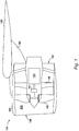
- FIG. 1 An electric ducted fan propulsor is shown in Figure 1 .
- the propulsor is shown generally at 101, attached to a wing 102 of an aircraft (not shown) by a pylon 103.
- the propulsor 101 Being a ducted fan, the propulsor 101 comprises a nacelle 104 which defines a duct 105 having an inlet 106 and a nozzle 107, and in which a propulsive fan 108 is located.
- the fan 108 raises the pressure of intake air, with swirl in the airflow being removed by outlet guide vanes 109. The airflow is directed through the nozzle 107 to generate thrust.
- the fan 108 is driven by an electric machine 110, in combination with a speed reduction device 111.
- the electric machine 110 is rated at a maximum continuous power of between 100 kilowatts and 100 megawatts. In a specific embodiment, the electric machine 110 is rated at a maximum continuous power of between 1 megawatt and 10 megawatts. In a more specific embodiment, the electric machine 110 is rated at 2 megawatts maximum continuous.
- the speed reduction device 111 is an epicyclic gearbox, but could be another form of reduction device such as a layshaft-based gear system or other suitable design.
- the epicyclic gearbox is a star gear system. Such an arrangement will be described with reference to Figure 3A .
- the epicyclic gearbox is a planetary gear system. Such an arrangement will be described with reference to Figure 3B .
- speed reduction device allows 111 allows the electric machine to operate at higher speed, and the fan to operate at lower speed. In this way, both components operate in their respective regimes of higher efficiency. Further, a larger fan is permitted due to the reduction of tip speed, and a smaller electric machine is permitted.
- the arrangement of Figure 1 permits a combination of a fan having a high hub-tip ratio, and a high aspect ratio electric machine, in terms of its length-to-diameter.
- the hub-tip ratio of the fan 108 in the present example is the ratio of the diameter D F of the leading edge of the fan blades 201, to the diameter of the diameter D H of the hub 202 at the leading edge 203 of the fan blades 201, i.e. the diameter of the inner gas-washed surface of the fan 108. It will be appreciated that the hub-tip ratio is a standard, well-known property of a fan, compressor, or turbine stage.
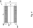
- the length of the electric machine as defined herein is the maximum length L A of the electromagnetically active components, whilst the diameter of the electric machine as defined herein is the maximum diameter D A of the electromagnetically active components. Examples of the definitions of length L A and diameter D A as applied to specific machine types will be described further with reference to Figures 4 and 5 .
- this combination of values advantageously enables the propulsor 101 to have a smaller diameter nozzle 107 for the same overall fan pressure ratio, which allows the pylon 103 to be made shorter. This results in, for a particular fan diameter D F , greater ground clearance, or a greater fan diameter D F for a particular ground clearance. Further, the reduction in pylon length and height results in a reduced moment on the wing 102, and a reduction in weight.
- the ratio L A /D A is from 1.1 to 1.7. The inventor has discovered that this allows a narrowed nozzle, along with a higher speed machine. In another specific embodiment, L A /D A is from 1.3 to 1.5. In a more specific embodiment, L A /D A is 1.4.
- the ratio D A /D F is from 0.35 to 0.45. In a specific embodiment, the ratio D A /D F is from 0.37 to 0.43. In a more specific embodiment, the ratio D A /D F may be 0.4.
- the hub-tip ratio of the fan 108 i.e. the value of D T /D H , may be from 0.25 to 0.31. In a specific embodiment, the hub-tip ratio may be from 0.27 to 0.29. In a more specific embodiment, the hub-tip ratio may be 0.28.
- the fan 108 has a tip pressure ratio (i.e. the ratio of the stagnation pressure immediately upstream of the tip of a fan blade 201, and immediately downstream of the fan blade 201) of from 1.3 to 1.7 at an altitude of 35,000 feet above sea level and a temperature of minus 54 degrees Celsius (i.e. ISA+0 standard conditions), and a true airspeed of Mach 0.85, i.e. during cruise conditions.
- the tip pressure ratio may be from 1.4 to 1.6 in the aforesaid conditions.
- the tip pressure ratio may be 1.5 in the aforesaid conditions.
- the tip pressure ratio may be 1.38 in the aforesaid conditions.
- FIG. 3A A diagram of one embodiment of the propulsor 101 is shown in Figure 3A , in which the speed reduction device 111 is a star-type epicyclic gearbox, indicated generally at 301.
- the electric machine 110 is coupled via an input shaft to a sun gear 302, which meshes with planet gears 303 mounted to a static carrier 304.
- the planet gears 303 transfer torque to a ring gear 305, which drives the fan 108.
- the reduction ratio of the star gearbox 301 is from 3:1 to 3.7:1.
- Use of a star gearbox may assist in terms of reducing complexity of installation due to the fixed carrier, for example with respect to lubrication systems.
- FIG. 3B A diagram of another embodiment of the propulsor 101 is shown in Figure 3B , in which the speed reduction device 111 is a planetary-type epicyclic gearbox, indicated generally at 311.
- the electric machine 110 is coupled via an input shaft to a sun gear 312, which meshes with planet gears 313 mounted in a rotating carrier 314.
- the planet gears 313 transfer torque to a static ring gear 315, with the carrier driving the fan 108.
- the reduction ratio of the planetary gearbox 311 is from 3:1 to 4.7:1.
- Use of a planetary gearbox may assist in terms of providing a greater reduction ratio for a given number of gear teeth.
- FIG. 4 An example of a configuration of the electric machine 101 is shown in cross-section through its central axis A-A in Figure 4 .
- This particular configuration is a radial flux electric machine 401, which comprises a stator 402 which surrounds a rotor 403.
- the stator 402 comprises a lamination stack of the known type.
- the electric machine is a permanent-magnet machine and thus the rotor 403 comprises permanent magnets, which interact with the magnetic field generated by windings in the stator 402 to generate torque.
- Alternative machine types such as induction machines may also be employed.
- end windings 404 emerge axially from the lamination stack of the stator 402.
- the electric machine 401 may be described as having an electromagnetically active length L A and an electromagnetically active diameter D A .
- electromagnetically active refers to the region responsible for generating torque upon the rotor.
- the length L A is the length of the lamination stack of the stator 402, and does not include the end windings 404 as they do not generate an appreciable torque upon the rotor 403.
- the diameter D A is the diameter of the lamination stack of the stator 302.
- the "electromagnetically active" parts of the electric machine 401 may be characterised as those components which form part of the torque-generating magnetic circuit in the machine.
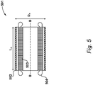
- FIG. 1 Another example configuration of the electric machine 101 is shown in cross-section through its central axis B-B in Figure 5 .
- This particular configuration is a radial flux electric machine 501, which comprises a rotor 502 which surrounds a stator 503.
- the electromagnetically active length L A of this machine is the length of the lamination stack of the stator 503, not including the end windings 504.
- the electromagnetically active diameter D A is, however, in this embodiment, the diameter of the rotor 502.
- machine 501 is a permanent-magnet machine, and thus the diameter D A is bounded by the greatest radial extent of the magnets therein. Should the machine instead be an induction machine, the diameter D A would be defined by the greatest radial extent of the rotor iron.
- the "electromagnetically active" parts of the electric machine 501 may be characterised as those components which form part of the torque-generating magnetic circuit in the machine.
Landscapes
- Engineering & Computer Science (AREA)
- Mechanical Engineering (AREA)
- General Engineering & Computer Science (AREA)
- Chemical & Material Sciences (AREA)
- Combustion & Propulsion (AREA)
- Power Engineering (AREA)
- Connection Of Motors, Electrical Generators, Mechanical Devices, And The Like (AREA)
- Aviation & Aerospace Engineering (AREA)
- Structures Of Non-Positive Displacement Pumps (AREA)
- Wind Motors (AREA)
Abstract
Description
- This disclosure relates to configurations of electric ducted fans for aircraft.
- Ducted fan-type propulsors are used for a large proportion of aircraft due to their greater efficiency and reduced noise due to lower tip losses than open propellers. Turbofans utilise a gas turbine core to drive a fan, the fan being larger than the core to produce a bypass flow responsible for the majority of thrust.
- Despite great advances in materials, compressor and turbine aerodynamics, and combustion efficiency, the gas turbine engines used in the cores of turbofans are still quite thermally inefficient. In particular, gas turbines are less efficient the smaller they are, which restricts possibilities in terms of the number of engines that may be installed on an airframe. Their fuel source is also not renewable. Further, the jet of high enthalpy exhaust from the core is responsible for a large amount of noise when it mixes with the exhausted bypass flow.
- It is therefore desirable to utilise electric machines in place of gas turbine engines in ducted fan arrangements to alleviate some or all of the aforesaid issues.
- The invention is directed towards electric ducted fans for aircraft.
- One such electric ducted fan comprises a nacelle defining a duct, and a propulsive fan in the duct having a fan diameter DF. An electric machine is configured to drive the fan via a speed reduction device having a reduction ratio of at least 3:1. The electric machine has an electromagnetically active length LA and an electromagnetically active diameter DA defining an aspect ratio (LA/DA) of from 0.8 to 2. A ratio of the electromagnetically active diameter DA to the fan diameter DF (DA/DF) is from 0.3 to 0.5.
- Electric ducted fans constructed in such a manner have various advantages, such as reduced nacelle drag, a shorter pylon, and increased ground clearance.
- Embodiments will now be described by way of example only with reference to the accompanying drawings, which are purely schematic and not to scale, and in which:
-
Figure 1 shows an electric ducted fan propulsor which uses an electric machine to drive a fan via a speed reduction device; -
Figure 2 shows definitions of various geometric parameters; -
Figure 3A shows the propulsor ofFigure 1 , using a star-type gearbox as the speed reduction device; -
Figure 3B shows the propulsor ofFigure 1 , using a planetary-type gearbox as the speed reduction device; -
Figure 4 shows one configuration of the electric machine; and -
Figure 5 shows another configuration of the electric machine. - An electric ducted fan propulsor is shown in
Figure 1 . - The propulsor is shown generally at 101, attached to a
wing 102 of an aircraft (not shown) by apylon 103. - Being a ducted fan, the
propulsor 101 comprises anacelle 104 which defines aduct 105 having aninlet 106 and anozzle 107, and in which apropulsive fan 108 is located. In operation, thefan 108 raises the pressure of intake air, with swirl in the airflow being removed byoutlet guide vanes 109. The airflow is directed through thenozzle 107 to generate thrust. - In the embodiment of
Figure 1 , thefan 108 is driven by anelectric machine 110, in combination with aspeed reduction device 111. - In the present embodiment, the
electric machine 110 is rated at a maximum continuous power of between 100 kilowatts and 100 megawatts. In a specific embodiment, theelectric machine 110 is rated at a maximum continuous power of between 1 megawatt and 10 megawatts. In a more specific embodiment, theelectric machine 110 is rated at 2 megawatts maximum continuous. - In the present example, the
speed reduction device 111 is an epicyclic gearbox, but could be another form of reduction device such as a layshaft-based gear system or other suitable design. In one example, the epicyclic gearbox is a star gear system. Such an arrangement will be described with reference toFigure 3A . In another example, the epicyclic gearbox is a planetary gear system. Such an arrangement will be described with reference toFigure 3B . - The use of speed reduction device allows 111 allows the electric machine to operate at higher speed, and the fan to operate at lower speed. In this way, both components operate in their respective regimes of higher efficiency. Further, a larger fan is permitted due to the reduction of tip speed, and a smaller electric machine is permitted.
- Thus, as illustrated in
Figure 2 , the arrangement ofFigure 1 permits a combination of a fan having a high hub-tip ratio, and a high aspect ratio electric machine, in terms of its length-to-diameter. - The hub-tip ratio of the
fan 108 in the present example is the ratio of the diameter DF of the leading edge of thefan blades 201, to the diameter of the diameter DH of thehub 202 at the leadingedge 203 of thefan blades 201, i.e. the diameter of the inner gas-washed surface of thefan 108. It will be appreciated that the hub-tip ratio is a standard, well-known property of a fan, compressor, or turbine stage. - The length of the electric machine as defined herein is the maximum length LA of the electromagnetically active components, whilst the diameter of the electric machine as defined herein is the maximum diameter DA of the electromagnetically active components. Examples of the definitions of length LA and diameter DA as applied to specific machine types will be described further with reference to
Figures 4 and5 . - Benefits are obtained by specifying the following parameters for the propulsor 101:
- (i) the aspect ratio of
electric machine 110, LA // DA (i.e. the value of LA divided by DA), being from 0.8 to 2; - (ii) the reduction ratio of the speed reduction device being at least 3:1;
- (iii) the ratio of the diameters of the electromagnetically active components in the electric machine and the fan, DA/DF (i.e. the value of DA divided by DF), being from 0.3 to 0.5.
- In particular, the inventor has discovered that this combination of values advantageously enables the
propulsor 101 to have asmaller diameter nozzle 107 for the same overall fan pressure ratio, which allows thepylon 103 to be made shorter. This results in, for a particular fan diameter DF, greater ground clearance, or a greater fan diameter DF for a particular ground clearance. Further, the reduction in pylon length and height results in a reduced moment on thewing 102, and a reduction in weight. - In a specific embodiment, the ratio LA/DA is from 1.1 to 1.7. The inventor has discovered that this allows a narrowed nozzle, along with a higher speed machine. In another specific embodiment, LA/DA is from 1.3 to 1.5. In a more specific embodiment, LA/DA is 1.4.
- In an additional or an alternative embodiment, the ratio DA/DF is from 0.35 to 0.45. In a specific embodiment, the ratio DA/DF is from 0.37 to 0.43. In a more specific embodiment, the ratio DA/DF may be 0.4.
- The hub-tip ratio of the
fan 108, i.e. the value of DT/DH, may be from 0.25 to 0.31. In a specific embodiment, the hub-tip ratio may be from 0.27 to 0.29. In a more specific embodiment, the hub-tip ratio may be 0.28. - In an embodiment, the
fan 108 has a tip pressure ratio (i.e. the ratio of the stagnation pressure immediately upstream of the tip of afan blade 201, and immediately downstream of the fan blade 201) of from 1.3 to 1.7 at an altitude of 35,000 feet above sea level and a temperature of minus 54 degrees Celsius (i.e. ISA+0 standard conditions), and a true airspeed of Mach 0.85, i.e. during cruise conditions. In a specific embodiment, the tip pressure ratio may be from 1.4 to 1.6 in the aforesaid conditions. In a more specific embodiment, the tip pressure ratio may be 1.5 in the aforesaid conditions. In another specific embodiment, the tip pressure ratio may be 1.38 in the aforesaid conditions. - A diagram of one embodiment of the
propulsor 101 is shown inFigure 3A , in which thespeed reduction device 111 is a star-type epicyclic gearbox, indicated generally at 301. Theelectric machine 110 is coupled via an input shaft to asun gear 302, which meshes withplanet gears 303 mounted to astatic carrier 304. The planet gears 303 transfer torque to aring gear 305, which drives thefan 108. In an embodiment, the reduction ratio of thestar gearbox 301 is from 3:1 to 3.7:1. Use of a star gearbox may assist in terms of reducing complexity of installation due to the fixed carrier, for example with respect to lubrication systems. - A diagram of another embodiment of the
propulsor 101 is shown inFigure 3B , in which thespeed reduction device 111 is a planetary-type epicyclic gearbox, indicated generally at 311. Theelectric machine 110 is coupled via an input shaft to asun gear 312, which meshes withplanet gears 313 mounted in arotating carrier 314. The planet gears 313 transfer torque to astatic ring gear 315, with the carrier driving thefan 108. In an embodiment, the reduction ratio of theplanetary gearbox 311 is from 3:1 to 4.7:1. Use of a planetary gearbox may assist in terms of providing a greater reduction ratio for a given number of gear teeth. - An example of a configuration of the
electric machine 101 is shown in cross-section through its central axis A-A inFigure 4 . This particular configuration is a radial fluxelectric machine 401, which comprises astator 402 which surrounds arotor 403. Thestator 402 comprises a lamination stack of the known type. In the present example, the electric machine is a permanent-magnet machine and thus therotor 403 comprises permanent magnets, which interact with the magnetic field generated by windings in thestator 402 to generate torque. Alternative machine types such as induction machines may also be employed. As a radial flux machine,end windings 404 emerge axially from the lamination stack of thestator 402. - As described previously, the
electric machine 401 may be described as having an electromagnetically active length LA and an electromagnetically active diameter DA. As used herein, "electromagnetically active" refers to the region responsible for generating torque upon the rotor. Thus in the present example, the length LA is the length of the lamination stack of thestator 402, and does not include theend windings 404 as they do not generate an appreciable torque upon therotor 403. Similarly, the diameter DA is the diameter of the lamination stack of thestator 302. - Put another way, the "electromagnetically active" parts of the
electric machine 401 may be characterised as those components which form part of the torque-generating magnetic circuit in the machine. - Those skilled in the art will appreciate how this definition may read across to other machine types such electromagnet-based synchronous motors, and axial flux machines, with the definitions of aspect ratio as set out herein also applying to these types of machine.
- Another example configuration of the
electric machine 101 is shown in cross-section through its central axis B-B inFigure 5 . This particular configuration is a radial fluxelectric machine 501, which comprises arotor 502 which surrounds astator 503. As withelectric machine 401, the electromagnetically active length LA of this machine is the length of the lamination stack of thestator 503, not including theend windings 504. The electromagnetically active diameter DA is, however, in this embodiment, the diameter of therotor 502. Again,machine 501 is a permanent-magnet machine, and thus the diameter DA is bounded by the greatest radial extent of the magnets therein. Should the machine instead be an induction machine, the diameter DA would be defined by the greatest radial extent of the rotor iron. - More generally, as described with reference to
Figure 4 , it will be appreciated the "electromagnetically active" parts of theelectric machine 501 may be characterised as those components which form part of the torque-generating magnetic circuit in the machine. - Various examples have been described, each of which feature various combinations of features. It will be appreciated by those skilled in the art that, except where clearly mutually exclusive, any of the features may be employed separately or in combination with any other features and the invention extends to and includes all combinations and subcombinations of one or more features described herein.
Claims (15)
- An electric ducted fan for an aircraft, comprising:a nacelle defining a duct;a propulsive fan in the duct having a fan diameter DF;an electric machine configured to drive the fan, the electric machine having an electromagnetically active length LA and an electromagnetically active diameter DA defining an aspect ratio (LA/DA) of from 0.8 to 2;a speed reduction device between the electric machine and the fan, having a reduction ratio of at least 3:1;and wherein a ratio of the electromagnetically active diameter DA to the fan diameter DF (DA/DF) is from 0.3 to 0.5.
- The electric ducted fan of claim 1, in which the aspect ratio (LA/DA)/is from 1.1 to 1.7.
- The electric ducted fan of claim 2, in which the aspect ratio (LA/DA)/is 1.4.
- The electric ducted fan of any preceding claim, in which the ratio of the electromagnetically active diameter DA to the fan diameter DF (DA/DF)/is from 0.35 to 0.45.
- The electric ducted fan of claim 4, in which the ratio of the electromagnetically active diameter DA to the fan diameter DF (DA/DF)/is from 0.37 to 0.43, for example 0.4.
- The electric ducted fan of any preceding claim, in which the electric machine is a radial flux electric machine.
- The electric ducted fan of claim 6, in which the stator is exterior to the rotor, the electromagnetically active diameter DA is the diameter of a stator stack, and the electromagnetically active length LA is the length of the stator stack.
- The electric ducted fan of claim 6, in which the stator is interior to the rotor, the electromagnetically active diameter DA is the diameter of the rotor, and the electromagnetically active length LA is the length of the stator stack.
- The electric ducted fan of any preceding claim, in which the fan has a hub-tip ratio of from 0.25 to 0.31.
- The electric ducted fan of claim 9, in which the fan has a hub-tip ratio of from 0.27 to 0.29, for example 0.28.
- The electric ducted fan of any preceding claim, in which the propulsive fan has a tip pressure ratio of from 1.3 to 1.7 at an altitude of 35,000 feet and a true airspeed of Mach 0.85.
- The electric ducted fan of claim 11, in which the propulsive fan has a tip pressure ratio of from 1.3 to 1.5 at an altitude of 35,000 feet and a true airspeed of Mach 0.85.
- The electric ducted fan of claim 12, in which the propulsive fan has a tip pressure ratio of 1.38 at an altitude of 35,000 feet and a true airspeed of Mach 0.85.
- The electric ducted fan of any one of claims 1 to 13, in which the speed reduction device is a star gearbox with a reduction ratio of at most 3.7:1.
- The electric ducted fan of any one of claims 1 to 13, in which the speed reduction device is a planetary gearbox with a reduction ratio of at most 4.7:1.
Applications Claiming Priority (1)
| Application Number | Priority Date | Filing Date | Title |
|---|---|---|---|
| GBGB1807770.1A GB201807770D0 (en) | 2018-05-14 | 2018-05-14 | Electric ducted fan |
Publications (2)
| Publication Number | Publication Date |
|---|---|
| EP3569857A1 true EP3569857A1 (en) | 2019-11-20 |
| EP3569857B1 EP3569857B1 (en) | 2022-06-08 |
Family
ID=62623390
Family Applications (1)
| Application Number | Title | Priority Date | Filing Date |
|---|---|---|---|
| EP19169237.5A Active EP3569857B1 (en) | 2018-05-14 | 2019-04-15 | Electric ducted fan |
Country Status (4)
| Country | Link |
|---|---|
| US (1) | US11077953B2 (en) |
| EP (1) | EP3569857B1 (en) |
| CN (1) | CN110486188B (en) |
| GB (1) | GB201807770D0 (en) |
Cited By (1)
| Publication number | Priority date | Publication date | Assignee | Title |
|---|---|---|---|---|
| EP4122817A1 (en) * | 2021-07-22 | 2023-01-25 | Rolls-Royce plc | Aircraft propulsion system |
Families Citing this family (8)
| Publication number | Priority date | Publication date | Assignee | Title |
|---|---|---|---|---|
| US20190288571A1 (en) * | 2018-02-20 | 2019-09-19 | Wright Electric Inc. | Electric motors for aircraft propulsion and associated systems and methods |
| US11554866B2 (en) * | 2021-03-11 | 2023-01-17 | Textron Innovations Inc. | Line replaceable centerbody assemblies for ducted propulsion |
| GB2610572A (en) | 2021-09-08 | 2023-03-15 | Rolls Royce Plc | An improved gas turbine engine |
| GB2610569A (en) | 2021-09-08 | 2023-03-15 | Rolls Royce Plc | An improved gas turbine engine |
| GB2610571A (en) * | 2021-09-08 | 2023-03-15 | Rolls Royce Plc | An improved gas turbine engine |
| GB2610565A (en) | 2021-09-08 | 2023-03-15 | Rolls Royce Plc | An improved gas turbine engine |
| GB2610568A (en) | 2021-09-08 | 2023-03-15 | Rolls Royce Plc | An improved gas turbine engine |
| GB2610567A (en) | 2021-09-08 | 2023-03-15 | Rolls Royce Plc | An improved gas turbine engine |
Citations (3)
| Publication number | Priority date | Publication date | Assignee | Title |
|---|---|---|---|---|
| US20170291693A1 (en) * | 2016-04-11 | 2017-10-12 | General Electric Company | Electric propulsion engine for an aircraft |
| US20170297727A1 (en) * | 2016-04-19 | 2017-10-19 | General Electric Company | Propulsion engine for an aircraft |
| EP3243753A1 (en) * | 2015-02-27 | 2017-11-15 | Mitsubishi Heavy Industries, Ltd. | Thrust force generation device and aircraft |
Family Cites Families (19)
| Publication number | Priority date | Publication date | Assignee | Title |
|---|---|---|---|---|
| US3078061A (en) * | 1961-01-10 | 1963-02-19 | Georges R P Marie | Pulse-jet aircraft and engine and diffusion systems for use therein |
| US4927329A (en) * | 1988-10-21 | 1990-05-22 | General Electric Company | Aircraft engine unducted fan blade pitch control system |
| US5149012A (en) * | 1991-09-10 | 1992-09-22 | Valverde Rene L | Turbocraft |
| US6895741B2 (en) * | 2003-06-23 | 2005-05-24 | Pratt & Whitney Canada Corp. | Differential geared turbine engine with torque modulation capability |
| JP4092728B2 (en) * | 2005-01-25 | 2008-05-28 | 独立行政法人 宇宙航空研究開発機構 | Aircraft propulsion system |
| US20080175703A1 (en) * | 2007-01-09 | 2008-07-24 | Sonic Blue Aerospace | Electric turbine bypass fan and compressor for hybrid propulsion |
| GB0809247D0 (en) * | 2008-05-22 | 2008-06-25 | Rolls Royce Plc | An electrical generator arrangement |
| US20100108806A1 (en) * | 2008-10-08 | 2010-05-06 | Searete Llc, A Limited Liability Corporation Of The State Of Delaware | Hybrid propulsive engine including at least one independently rotatable propeller/fan |
| FR2979614B1 (en) * | 2011-09-04 | 2013-09-20 | Eric Chantriaux | ELECTROMAGNETIC POWER TRANSMISSION FOR AN AIRCRAFT WITH A ROTARY OR FIXED SAIL. |
| FR2979615B1 (en) * | 2011-09-04 | 2013-09-20 | Eric Chantriaux | AIRCRAFT EQUIPPED WITH AN ELECTROMOTEUR GROUP DISTRIBUTED TO FREE WHEELS. |
| GB201116759D0 (en) * | 2011-09-29 | 2011-11-09 | Rolls Royce Plc | A superconducting electrical system |
| CN105416573B (en) | 2015-12-03 | 2017-05-17 | 北京航空航天大学 | Light efficient low-noise duct type two-stage electric fan propeller |
| US20170167438A1 (en) * | 2015-12-11 | 2017-06-15 | General Electric Company | Gas Turbine Engine |
| US20180118364A1 (en) * | 2016-11-03 | 2018-05-03 | The Boeing Company | System and method for augmenting a primary powerplant |
| CN206615387U (en) | 2017-04-01 | 2017-11-07 | 张家港致盈电子技术有限公司 | A kind of coaxial opposed pair of oar power duct |
| CN107719671A (en) | 2017-10-09 | 2018-02-23 | 武汉卓尔无人机制造有限公司 | A kind of ducted fan promotes all-electric unmanned plane |
| US11466643B2 (en) * | 2018-06-22 | 2022-10-11 | Sonic Blue Aerospace, Inc. | Superconducting ultra power efficient radial fan augmented nano-aerodrive (superfan) |
| US11485503B2 (en) * | 2019-03-29 | 2022-11-01 | Pratt & Whitney Canada Corp. | Hybrid aircraft propulsion power plants |
| US11718395B2 (en) * | 2019-09-13 | 2023-08-08 | Rolls-Royce Corporation | Electrically controlled vertical takeoff and landing aircraft system and method |
-
2018
- 2018-05-14 GB GBGB1807770.1A patent/GB201807770D0/en not_active Ceased
-
2019
- 2019-04-15 EP EP19169237.5A patent/EP3569857B1/en active Active
- 2019-04-22 US US16/390,555 patent/US11077953B2/en active Active
- 2019-05-14 CN CN201910397853.6A patent/CN110486188B/en active Active
Patent Citations (3)
| Publication number | Priority date | Publication date | Assignee | Title |
|---|---|---|---|---|
| EP3243753A1 (en) * | 2015-02-27 | 2017-11-15 | Mitsubishi Heavy Industries, Ltd. | Thrust force generation device and aircraft |
| US20170291693A1 (en) * | 2016-04-11 | 2017-10-12 | General Electric Company | Electric propulsion engine for an aircraft |
| US20170297727A1 (en) * | 2016-04-19 | 2017-10-19 | General Electric Company | Propulsion engine for an aircraft |
Non-Patent Citations (1)
| Title |
|---|
| JASON WELSTEAD ET AL: "Conceptual Design of a Single-Aisle Turboelectric Commercial Transport with Fuselage Boundary Layer Ingestion", 54TH AIAA AEROSPACE SCIENCES MEETING, 4 January 2016 (2016-01-04), Reston, Virginia, XP055554823, ISBN: 978-1-62410-393-3, DOI: 10.2514/6.2016-1027 * |
Cited By (2)
| Publication number | Priority date | Publication date | Assignee | Title |
|---|---|---|---|---|
| EP4122817A1 (en) * | 2021-07-22 | 2023-01-25 | Rolls-Royce plc | Aircraft propulsion system |
| US12275530B2 (en) | 2021-07-22 | 2025-04-15 | Rolls-Royce Plc | Aircraft propulsion system |
Also Published As
| Publication number | Publication date |
|---|---|
| CN110486188B (en) | 2023-11-10 |
| GB201807770D0 (en) | 2018-06-27 |
| EP3569857B1 (en) | 2022-06-08 |
| US11077953B2 (en) | 2021-08-03 |
| CN110486188A (en) | 2019-11-22 |
| US20190344900A1 (en) | 2019-11-14 |
Similar Documents
| Publication | Publication Date | Title |
|---|---|---|
| US11077953B2 (en) | Electric ducted fan | |
| US11313440B2 (en) | Epicyclic gearbox | |
| CN109071030B (en) | Propulsion engine for an aircraft | |
| EP3569856B1 (en) | Electric ducted fan | |
| EP3023601B1 (en) | Tail cone generator with integral speed increasing gearbox | |
| EP2613033B1 (en) | Magnetically coupled contra-rotating propulsion stages | |
| US8198744B2 (en) | Integrated boost cavity ring generator for turbofan and turboshaft engines | |
| US20230399983A1 (en) | Differential gearbox assembly for a turbine engine | |
| EP3628587A1 (en) | Aircraft propulsion system | |
| EP3832097B1 (en) | Gas turbine engine | |
| US11739694B2 (en) | Embedded electric motor assembly | |
| US12388322B2 (en) | Electric generator behind fan in turbine engine | |
| EP4509702A1 (en) | Hybrid-electric propulsion system for aeronautical applications | |
| EP3617059B1 (en) | Turbomachine | |
| US12275530B2 (en) | Aircraft propulsion system | |
| US20260117708A1 (en) | Power transfer system | |
| EP3623285B1 (en) | Turbomachine | |
| CN121932286A (en) | Power transmission system |
Legal Events
| Date | Code | Title | Description |
|---|---|---|---|
| PUAI | Public reference made under article 153(3) epc to a published international application that has entered the european phase |
Free format text: ORIGINAL CODE: 0009012 |
|
| STAA | Information on the status of an ep patent application or granted ep patent |
Free format text: STATUS: THE APPLICATION HAS BEEN PUBLISHED |
|
| AK | Designated contracting states |
Kind code of ref document: A1 Designated state(s): AL AT BE BG CH CY CZ DE DK EE ES FI FR GB GR HR HU IE IS IT LI LT LU LV MC MK MT NL NO PL PT RO RS SE SI SK SM TR |
|
| RAP1 | Party data changed (applicant data changed or rights of an application transferred) |
Owner name: ROLLS-ROYCE PLC |
|
| STAA | Information on the status of an ep patent application or granted ep patent |
Free format text: STATUS: REQUEST FOR EXAMINATION WAS MADE |
|
| 17P | Request for examination filed |
Effective date: 20200619 |
|
| RBV | Designated contracting states (corrected) |
Designated state(s): AL AT BE BG CH CY CZ DE DK EE ES FI FR GB GR HR HU IE IS IT LI LT LU LV MC MK MT NL NO PL PT RO RS SE SI SK SM TR |
|
| GRAP | Despatch of communication of intention to grant a patent |
Free format text: ORIGINAL CODE: EPIDOSNIGR1 |
|
| STAA | Information on the status of an ep patent application or granted ep patent |
Free format text: STATUS: GRANT OF PATENT IS INTENDED |
|
| INTG | Intention to grant announced |
Effective date: 20220401 |
|
| GRAS | Grant fee paid |
Free format text: ORIGINAL CODE: EPIDOSNIGR3 |
|
| GRAA | (expected) grant |
Free format text: ORIGINAL CODE: 0009210 |
|
| STAA | Information on the status of an ep patent application or granted ep patent |
Free format text: STATUS: THE PATENT HAS BEEN GRANTED |
|
| AK | Designated contracting states |
Kind code of ref document: B1 Designated state(s): AL AT BE BG CH CY CZ DE DK EE ES FI FR GB GR HR HU IE IS IT LI LT LU LV MC MK MT NL NO PL PT RO RS SE SI SK SM TR |
|
| REG | Reference to a national code |
Ref country code: AT Ref legal event code: REF Ref document number: 1497079 Country of ref document: AT Kind code of ref document: T Effective date: 20220615 Ref country code: CH Ref legal event code: EP |
|
| REG | Reference to a national code |
Ref country code: DE Ref legal event code: R096 Ref document number: 602019015577 Country of ref document: DE |
|
| REG | Reference to a national code |
Ref country code: IE Ref legal event code: FG4D |
|
| REG | Reference to a national code |
Ref country code: LT Ref legal event code: MG9D |
|
| REG | Reference to a national code |
Ref country code: NL Ref legal event code: MP Effective date: 20220608 |
|
| PG25 | Lapsed in a contracting state [announced via postgrant information from national office to epo] |
Ref country code: SE Free format text: LAPSE BECAUSE OF FAILURE TO SUBMIT A TRANSLATION OF THE DESCRIPTION OR TO PAY THE FEE WITHIN THE PRESCRIBED TIME-LIMIT Effective date: 20220608 Ref country code: NO Free format text: LAPSE BECAUSE OF FAILURE TO SUBMIT A TRANSLATION OF THE DESCRIPTION OR TO PAY THE FEE WITHIN THE PRESCRIBED TIME-LIMIT Effective date: 20220908 Ref country code: LT Free format text: LAPSE BECAUSE OF FAILURE TO SUBMIT A TRANSLATION OF THE DESCRIPTION OR TO PAY THE FEE WITHIN THE PRESCRIBED TIME-LIMIT Effective date: 20220608 Ref country code: HR Free format text: LAPSE BECAUSE OF FAILURE TO SUBMIT A TRANSLATION OF THE DESCRIPTION OR TO PAY THE FEE WITHIN THE PRESCRIBED TIME-LIMIT Effective date: 20220608 Ref country code: GR Free format text: LAPSE BECAUSE OF FAILURE TO SUBMIT A TRANSLATION OF THE DESCRIPTION OR TO PAY THE FEE WITHIN THE PRESCRIBED TIME-LIMIT Effective date: 20220909 Ref country code: FI Free format text: LAPSE BECAUSE OF FAILURE TO SUBMIT A TRANSLATION OF THE DESCRIPTION OR TO PAY THE FEE WITHIN THE PRESCRIBED TIME-LIMIT Effective date: 20220608 Ref country code: ES Free format text: LAPSE BECAUSE OF FAILURE TO SUBMIT A TRANSLATION OF THE DESCRIPTION OR TO PAY THE FEE WITHIN THE PRESCRIBED TIME-LIMIT Effective date: 20220608 Ref country code: BG Free format text: LAPSE BECAUSE OF FAILURE TO SUBMIT A TRANSLATION OF THE DESCRIPTION OR TO PAY THE FEE WITHIN THE PRESCRIBED TIME-LIMIT Effective date: 20220908 |
|
| REG | Reference to a national code |
Ref country code: AT Ref legal event code: MK05 Ref document number: 1497079 Country of ref document: AT Kind code of ref document: T Effective date: 20220608 |
|
| PG25 | Lapsed in a contracting state [announced via postgrant information from national office to epo] |
Ref country code: RS Free format text: LAPSE BECAUSE OF FAILURE TO SUBMIT A TRANSLATION OF THE DESCRIPTION OR TO PAY THE FEE WITHIN THE PRESCRIBED TIME-LIMIT Effective date: 20220608 Ref country code: LV Free format text: LAPSE BECAUSE OF FAILURE TO SUBMIT A TRANSLATION OF THE DESCRIPTION OR TO PAY THE FEE WITHIN THE PRESCRIBED TIME-LIMIT Effective date: 20220608 |
|
| PG25 | Lapsed in a contracting state [announced via postgrant information from national office to epo] |
Ref country code: NL Free format text: LAPSE BECAUSE OF FAILURE TO SUBMIT A TRANSLATION OF THE DESCRIPTION OR TO PAY THE FEE WITHIN THE PRESCRIBED TIME-LIMIT Effective date: 20220608 |
|
| PG25 | Lapsed in a contracting state [announced via postgrant information from national office to epo] |
Ref country code: SM Free format text: LAPSE BECAUSE OF FAILURE TO SUBMIT A TRANSLATION OF THE DESCRIPTION OR TO PAY THE FEE WITHIN THE PRESCRIBED TIME-LIMIT Effective date: 20220608 Ref country code: SK Free format text: LAPSE BECAUSE OF FAILURE TO SUBMIT A TRANSLATION OF THE DESCRIPTION OR TO PAY THE FEE WITHIN THE PRESCRIBED TIME-LIMIT Effective date: 20220608 Ref country code: RO Free format text: LAPSE BECAUSE OF FAILURE TO SUBMIT A TRANSLATION OF THE DESCRIPTION OR TO PAY THE FEE WITHIN THE PRESCRIBED TIME-LIMIT Effective date: 20220608 Ref country code: PT Free format text: LAPSE BECAUSE OF FAILURE TO SUBMIT A TRANSLATION OF THE DESCRIPTION OR TO PAY THE FEE WITHIN THE PRESCRIBED TIME-LIMIT Effective date: 20221010 Ref country code: EE Free format text: LAPSE BECAUSE OF FAILURE TO SUBMIT A TRANSLATION OF THE DESCRIPTION OR TO PAY THE FEE WITHIN THE PRESCRIBED TIME-LIMIT Effective date: 20220608 Ref country code: CZ Free format text: LAPSE BECAUSE OF FAILURE TO SUBMIT A TRANSLATION OF THE DESCRIPTION OR TO PAY THE FEE WITHIN THE PRESCRIBED TIME-LIMIT Effective date: 20220608 Ref country code: AT Free format text: LAPSE BECAUSE OF FAILURE TO SUBMIT A TRANSLATION OF THE DESCRIPTION OR TO PAY THE FEE WITHIN THE PRESCRIBED TIME-LIMIT Effective date: 20220608 |
|
| PG25 | Lapsed in a contracting state [announced via postgrant information from national office to epo] |
Ref country code: PL Free format text: LAPSE BECAUSE OF FAILURE TO SUBMIT A TRANSLATION OF THE DESCRIPTION OR TO PAY THE FEE WITHIN THE PRESCRIBED TIME-LIMIT Effective date: 20220608 Ref country code: IS Free format text: LAPSE BECAUSE OF FAILURE TO SUBMIT A TRANSLATION OF THE DESCRIPTION OR TO PAY THE FEE WITHIN THE PRESCRIBED TIME-LIMIT Effective date: 20221008 |
|
| REG | Reference to a national code |
Ref country code: DE Ref legal event code: R097 Ref document number: 602019015577 Country of ref document: DE |
|
| PG25 | Lapsed in a contracting state [announced via postgrant information from national office to epo] |
Ref country code: AL Free format text: LAPSE BECAUSE OF FAILURE TO SUBMIT A TRANSLATION OF THE DESCRIPTION OR TO PAY THE FEE WITHIN THE PRESCRIBED TIME-LIMIT Effective date: 20220608 |
|
| PLBE | No opposition filed within time limit |
Free format text: ORIGINAL CODE: 0009261 |
|
| STAA | Information on the status of an ep patent application or granted ep patent |
Free format text: STATUS: NO OPPOSITION FILED WITHIN TIME LIMIT |
|
| PG25 | Lapsed in a contracting state [announced via postgrant information from national office to epo] |
Ref country code: DK Free format text: LAPSE BECAUSE OF FAILURE TO SUBMIT A TRANSLATION OF THE DESCRIPTION OR TO PAY THE FEE WITHIN THE PRESCRIBED TIME-LIMIT Effective date: 20220608 |
|
| 26N | No opposition filed |
Effective date: 20230310 |
|
| PG25 | Lapsed in a contracting state [announced via postgrant information from national office to epo] |
Ref country code: SI Free format text: LAPSE BECAUSE OF FAILURE TO SUBMIT A TRANSLATION OF THE DESCRIPTION OR TO PAY THE FEE WITHIN THE PRESCRIBED TIME-LIMIT Effective date: 20220608 |
|
| P01 | Opt-out of the competence of the unified patent court (upc) registered |
Effective date: 20230528 |
|
| REG | Reference to a national code |
Ref country code: CH Ref legal event code: PL |
|
| PG25 | Lapsed in a contracting state [announced via postgrant information from national office to epo] |
Ref country code: LU Free format text: LAPSE BECAUSE OF NON-PAYMENT OF DUE FEES Effective date: 20230415 |
|
| REG | Reference to a national code |
Ref country code: BE Ref legal event code: MM Effective date: 20230430 |
|
| PG25 | Lapsed in a contracting state [announced via postgrant information from national office to epo] |
Ref country code: MC Free format text: LAPSE BECAUSE OF FAILURE TO SUBMIT A TRANSLATION OF THE DESCRIPTION OR TO PAY THE FEE WITHIN THE PRESCRIBED TIME-LIMIT Effective date: 20220608 |
|
| PG25 | Lapsed in a contracting state [announced via postgrant information from national office to epo] |
Ref country code: MC Free format text: LAPSE BECAUSE OF FAILURE TO SUBMIT A TRANSLATION OF THE DESCRIPTION OR TO PAY THE FEE WITHIN THE PRESCRIBED TIME-LIMIT Effective date: 20220608 Ref country code: LI Free format text: LAPSE BECAUSE OF NON-PAYMENT OF DUE FEES Effective date: 20230430 Ref country code: IT Free format text: LAPSE BECAUSE OF FAILURE TO SUBMIT A TRANSLATION OF THE DESCRIPTION OR TO PAY THE FEE WITHIN THE PRESCRIBED TIME-LIMIT Effective date: 20220608 Ref country code: CH Free format text: LAPSE BECAUSE OF NON-PAYMENT OF DUE FEES Effective date: 20230430 |
|
| REG | Reference to a national code |
Ref country code: IE Ref legal event code: MM4A |
|
| PG25 | Lapsed in a contracting state [announced via postgrant information from national office to epo] |
Ref country code: BE Free format text: LAPSE BECAUSE OF NON-PAYMENT OF DUE FEES Effective date: 20230430 |
|
| PG25 | Lapsed in a contracting state [announced via postgrant information from national office to epo] |
Ref country code: IE Free format text: LAPSE BECAUSE OF NON-PAYMENT OF DUE FEES Effective date: 20230415 |
|
| PG25 | Lapsed in a contracting state [announced via postgrant information from national office to epo] |
Ref country code: IE Free format text: LAPSE BECAUSE OF NON-PAYMENT OF DUE FEES Effective date: 20230415 |
|
| PG25 | Lapsed in a contracting state [announced via postgrant information from national office to epo] |
Ref country code: BG Free format text: LAPSE BECAUSE OF FAILURE TO SUBMIT A TRANSLATION OF THE DESCRIPTION OR TO PAY THE FEE WITHIN THE PRESCRIBED TIME-LIMIT Effective date: 20220608 |
|
| PG25 | Lapsed in a contracting state [announced via postgrant information from national office to epo] |
Ref country code: BG Free format text: LAPSE BECAUSE OF FAILURE TO SUBMIT A TRANSLATION OF THE DESCRIPTION OR TO PAY THE FEE WITHIN THE PRESCRIBED TIME-LIMIT Effective date: 20220608 |
|
| PGFP | Annual fee paid to national office [announced via postgrant information from national office to epo] |
Ref country code: DE Payment date: 20250428 Year of fee payment: 7 |
|
| PGFP | Annual fee paid to national office [announced via postgrant information from national office to epo] |
Ref country code: GB Payment date: 20250422 Year of fee payment: 7 |
|
| PGFP | Annual fee paid to national office [announced via postgrant information from national office to epo] |
Ref country code: FR Payment date: 20250424 Year of fee payment: 7 |
|
| PG25 | Lapsed in a contracting state [announced via postgrant information from national office to epo] |
Ref country code: CY Free format text: LAPSE BECAUSE OF FAILURE TO SUBMIT A TRANSLATION OF THE DESCRIPTION OR TO PAY THE FEE WITHIN THE PRESCRIBED TIME-LIMIT; INVALID AB INITIO Effective date: 20190415 |
|
| PG25 | Lapsed in a contracting state [announced via postgrant information from national office to epo] |
Ref country code: HU Free format text: LAPSE BECAUSE OF FAILURE TO SUBMIT A TRANSLATION OF THE DESCRIPTION OR TO PAY THE FEE WITHIN THE PRESCRIBED TIME-LIMIT; INVALID AB INITIO Effective date: 20190415 |
|
| PG25 | Lapsed in a contracting state [announced via postgrant information from national office to epo] |
Ref country code: TR Free format text: LAPSE BECAUSE OF FAILURE TO SUBMIT A TRANSLATION OF THE DESCRIPTION OR TO PAY THE FEE WITHIN THE PRESCRIBED TIME-LIMIT Effective date: 20220608 |