EP3569746B1 - Composite yarn for the position sensitive capacitive touch sensing - Google Patents
Composite yarn for the position sensitive capacitive touch sensing Download PDFInfo
- Publication number
- EP3569746B1 EP3569746B1 EP19174913.4A EP19174913A EP3569746B1 EP 3569746 B1 EP3569746 B1 EP 3569746B1 EP 19174913 A EP19174913 A EP 19174913A EP 3569746 B1 EP3569746 B1 EP 3569746B1
- Authority
- EP
- European Patent Office
- Prior art keywords
- yarn
- composite
- electrically
- electrically conductive
- electrically resistive
- Prior art date
- Legal status (The legal status is an assumption and is not a legal conclusion. Google has not performed a legal analysis and makes no representation as to the accuracy of the status listed.)
- Active
Links
Images


Classifications
-
- G—PHYSICS
- G06—COMPUTING OR CALCULATING; COUNTING
- G06F—ELECTRIC DIGITAL DATA PROCESSING
- G06F3/00—Input arrangements for transferring data to be processed into a form capable of being handled by the computer; Output arrangements for transferring data from processing unit to output unit, e.g. interface arrangements
- G06F3/01—Input arrangements or combined input and output arrangements for interaction between user and computer
- G06F3/03—Arrangements for converting the position or the displacement of a member into a coded form
- G06F3/041—Digitisers, e.g. for touch screens or touch pads, characterised by the transducing means
- G06F3/044—Digitisers, e.g. for touch screens or touch pads, characterised by the transducing means by capacitive means
- G06F3/0446—Digitisers, e.g. for touch screens or touch pads, characterised by the transducing means by capacitive means using a grid-like structure of electrodes in at least two directions, e.g. using row and column electrodes
-
- D—TEXTILES; PAPER
- D02—YARNS; MECHANICAL FINISHING OF YARNS OR ROPES; WARPING OR BEAMING
- D02G—CRIMPING OR CURLING FIBRES, FILAMENTS, THREADS, OR YARNS; YARNS OR THREADS
- D02G3/00—Yarns or threads, e.g. fancy yarns; Processes or apparatus for the production thereof, not otherwise provided for
- D02G3/44—Yarns or threads characterised by the purpose for which they are designed
- D02G3/441—Yarns or threads with antistatic, conductive or radiation-shielding properties
-
- D—TEXTILES; PAPER
- D02—YARNS; MECHANICAL FINISHING OF YARNS OR ROPES; WARPING OR BEAMING
- D02G—CRIMPING OR CURLING FIBRES, FILAMENTS, THREADS, OR YARNS; YARNS OR THREADS
- D02G3/00—Yarns or threads, e.g. fancy yarns; Processes or apparatus for the production thereof, not otherwise provided for
- D02G3/02—Yarns or threads characterised by the material or by the materials from which they are made
- D02G3/04—Blended or other yarns or threads containing components made from different materials
-
- D—TEXTILES; PAPER
- D02—YARNS; MECHANICAL FINISHING OF YARNS OR ROPES; WARPING OR BEAMING
- D02G—CRIMPING OR CURLING FIBRES, FILAMENTS, THREADS, OR YARNS; YARNS OR THREADS
- D02G3/00—Yarns or threads, e.g. fancy yarns; Processes or apparatus for the production thereof, not otherwise provided for
- D02G3/02—Yarns or threads characterised by the material or by the materials from which they are made
- D02G3/12—Threads containing metallic filaments or strips
-
- D—TEXTILES; PAPER
- D03—WEAVING
- D03D—WOVEN FABRICS; METHODS OF WEAVING; LOOMS
- D03D1/00—Woven fabrics designed to make specified articles
- D03D1/0088—Fabrics having an electronic function
-
- G—PHYSICS
- G06—COMPUTING OR CALCULATING; COUNTING
- G06F—ELECTRIC DIGITAL DATA PROCESSING
- G06F3/00—Input arrangements for transferring data to be processed into a form capable of being handled by the computer; Output arrangements for transferring data from processing unit to output unit, e.g. interface arrangements
- G06F3/01—Input arrangements or combined input and output arrangements for interaction between user and computer
- G06F3/03—Arrangements for converting the position or the displacement of a member into a coded form
- G06F3/041—Digitisers, e.g. for touch screens or touch pads, characterised by the transducing means
- G06F3/0416—Control or interface arrangements specially adapted for digitisers
-
- G—PHYSICS
- G06—COMPUTING OR CALCULATING; COUNTING
- G06F—ELECTRIC DIGITAL DATA PROCESSING
- G06F3/00—Input arrangements for transferring data to be processed into a form capable of being handled by the computer; Output arrangements for transferring data from processing unit to output unit, e.g. interface arrangements
- G06F3/01—Input arrangements or combined input and output arrangements for interaction between user and computer
- G06F3/03—Arrangements for converting the position or the displacement of a member into a coded form
- G06F3/041—Digitisers, e.g. for touch screens or touch pads, characterised by the transducing means
- G06F3/0416—Control or interface arrangements specially adapted for digitisers
- G06F3/04164—Connections between sensors and controllers, e.g. routing lines between electrodes and connection pads
-
- G—PHYSICS
- G06—COMPUTING OR CALCULATING; COUNTING
- G06F—ELECTRIC DIGITAL DATA PROCESSING
- G06F3/00—Input arrangements for transferring data to be processed into a form capable of being handled by the computer; Output arrangements for transferring data from processing unit to output unit, e.g. interface arrangements
- G06F3/01—Input arrangements or combined input and output arrangements for interaction between user and computer
- G06F3/03—Arrangements for converting the position or the displacement of a member into a coded form
- G06F3/041—Digitisers, e.g. for touch screens or touch pads, characterised by the transducing means
- G06F3/044—Digitisers, e.g. for touch screens or touch pads, characterised by the transducing means by capacitive means
-
- G—PHYSICS
- G06—COMPUTING OR CALCULATING; COUNTING
- G06F—ELECTRIC DIGITAL DATA PROCESSING
- G06F3/00—Input arrangements for transferring data to be processed into a form capable of being handled by the computer; Output arrangements for transferring data from processing unit to output unit, e.g. interface arrangements
- G06F3/01—Input arrangements or combined input and output arrangements for interaction between user and computer
- G06F3/03—Arrangements for converting the position or the displacement of a member into a coded form
- G06F3/041—Digitisers, e.g. for touch screens or touch pads, characterised by the transducing means
- G06F3/044—Digitisers, e.g. for touch screens or touch pads, characterised by the transducing means by capacitive means
- G06F3/0448—Details of the electrode shape, e.g. for enhancing the detection of touches, for generating specific electric field shapes, for enhancing display quality
-
- D—TEXTILES; PAPER
- D10—INDEXING SCHEME ASSOCIATED WITH SUBLASSES OF SECTION D, RELATING TO TEXTILES
- D10B—INDEXING SCHEME ASSOCIATED WITH SUBLASSES OF SECTION D, RELATING TO TEXTILES
- D10B2101/00—Inorganic fibres
- D10B2101/20—Metallic fibres
-
- D—TEXTILES; PAPER
- D10—INDEXING SCHEME ASSOCIATED WITH SUBLASSES OF SECTION D, RELATING TO TEXTILES
- D10B—INDEXING SCHEME ASSOCIATED WITH SUBLASSES OF SECTION D, RELATING TO TEXTILES
- D10B2401/00—Physical properties
- D10B2401/16—Physical properties antistatic; conductive
-
- G—PHYSICS
- G06—COMPUTING OR CALCULATING; COUNTING
- G06F—ELECTRIC DIGITAL DATA PROCESSING
- G06F2203/00—Indexing scheme relating to G06F3/00 - G06F3/048
- G06F2203/041—Indexing scheme relating to G06F3/041 - G06F3/045
- G06F2203/04102—Flexible digitiser, i.e. constructional details for allowing the whole digitising part of a device to be flexed or rolled like a sheet of paper
-
- G—PHYSICS
- G06—COMPUTING OR CALCULATING; COUNTING
- G06F—ELECTRIC DIGITAL DATA PROCESSING
- G06F2203/00—Indexing scheme relating to G06F3/00 - G06F3/048
- G06F2203/041—Indexing scheme relating to G06F3/041 - G06F3/045
- G06F2203/04103—Manufacturing, i.e. details related to manufacturing processes specially suited for touch sensitive devices
Definitions
- the present invention relates to the field of the capacitive sensing.
- the present invention relates to a composite yarn for a fabric implementing a touch sensor.
- Capacitive touch sensors comprise a plurality of electrically conductive wires, electrically insulated from each other, and arranged to form a grid.
- Capacitive touch sensors may employ the "self-capacitance sensing" technique wherein each sensing wire is connected to a controller configured to evaluate the capacitance value of each sensing wire, i.e. independently to each other.
- the controller is configured to detect the change of value in the capacitance of each sensing wire due to the parasitic capacitance provided by an object (e.g. a finger) touching the sensing wire.
- the position of a touch event is determined by the controller by detecting which sensing wires (i.e. which rows and columns) of the capacitive grid are touched, so that the position of the touch is determined as X, Y coordinates on the capacitive grid.
- Some capacitive touch sensors employ the "mutual capacitance sensing" technique wherein the controller is configured to evaluate sequentially the mutual capacitance value at each intersection of sensing wires. In other words, the controller is configured to evaluate the capacitance value of each capacitor formed between sensing wires for each row and each column of the capacitive grid. A touch of an object (e.g. a finger) on the capacitive grid is detected as a change of value in the mutual capacitance.
- the controller is configured to evaluate sequentially the mutual capacitance value at each intersection of sensing wires.
- the controller is configured to evaluate the capacitance value of each capacitor formed between sensing wires for each row and each column of the capacitive grid.
- a touch of an object e.g. a finger
- Capacitive touch sensors embedded in a fabric are known.
- US2016048235A1 discloses a fabric implementing a capacitive touch sensing comprising a plurality of electrically conductive wires, electrically insulated from each other, and arranged to form a grid.
- Each wire is connected to a controller configured to evaluate the capacitance value of each wire (i.e. using the "self-capacitance sensing").
- the controller detects the position of a touch event by detecting which horizontal wire and which vertical wire is touched, by detecting changes in capacitance of each respective wire of the capacitive grid.
- the controller uses the intersection of the crossing wires that are touched to determine the position of the touch event on the capacitive grid, so that the position of the touch is determined as X, Y coordinates on the capacitive grid.
- the capacitive grid can be embedded in a fabric by using the electrically conductive wires as weft yarns and warp yarns.
- each electrically conductive wire of the capacitive grid (vertical and horizontal wires) have to be electrically connected to a sensing circuit by means of electrical contacts arranged along both the vertical side and the horizontal side of the capacitive grid.
- the routing of the electrical connections between the capacitive grid and the sensing circuit may be very complex when the capacitive grid has a great number of electrically conductive wires.
- a touch sensor having a substantially rectangular form (i.e. having a number of horizontal wires different with respect to the number of vertical wires) or provided with electrically conductive wires arranged parallel along only one direction (e.g. in case of a swipe sensor)
- the arrangement of the electrical contacts and the routing of the electrical connections between the conductive wires and the sensing circuit may be very difficult to be designed, making the production of the touch sensor complex and expensive and in some cases causing a stiffening of the touch sensor structure.
- Document WO 2004/003273 A2 discloses a coaxial conductive yarn structure 100 comprising an inner conductive yarn 102 extending in a first direction and having a plurality of first conductive strands being twisted together; an outer conductive yarn 106 having a plurality of second conductive strands 108 being twisted together, the outer conductive yarn 1006 being wrapped around the inner conductive yarn 102 in a second direction transverse to the first direction and substantially covering the inner conductive yarn 102; and at least one insulating layer 104 for electrically isolating the inner and outer conductive yarns from each other.
- the above structure is described as able to reduce signal crosstalk between adjacent lines in woven electrical networks, improving signal integrity in fabric-based electrical circuits.
- Document EP 1176610 A1 discloses a thin wire for production of a fiber material.
- a woven or nonwoven fabric comprises a metal wire which is coated with an organic-based protective, electrically conductive layer.
- a method of production of an electrically conductive fabric is also disclosed in which, first a compound thread is produced by covering the wire with textile fibers, and subsequently such a thread is used to produce of the fabric.
- An interactive textile includes a grid of conductive thread woven into the interactive textile to form a capacitive touch sensor that is configured to detect touch-input.
- the interactive textile can process the touch-input to generate touch data that is useable to initiate functionality at various remote devices that are wirelessly coupled to the interactive textile.
- the interactive textile disclosed may aid users in controlling volume on a stereo, pausing a movie playing on a television, or selecting a webpage on a desktop computer.
- WO2014092781 A1 discloses a flexible electrically functional woven or nonwoven fabric comprising a plurality of textile fibers; and at least one flexible electrically functional fiber capable of at least one of providing energy storage and/or electrical interconnection to an electrical component.
- the fabric may comprise a microprocessor, a power source, a switch, a transducer, a light emitting device, a data storage device, a transmitter, a receiver or any combination thereof.
- An object of the present invention is to overcome the drawbacks of the prior art cited above and to provide a composite yarn that allows to produce a touch sensor having a simple routing of the electrical connections.
- a further object of the present invention is to provide a touch sensor and a method for detecting the location of touch event on a support layer (for example a fabric) able to detect the touch event in a precise and reliable way.
- a support layer for example a fabric
- the composite yarn comprises an electrically conductive yarn and an electrically resistive yarn, wherein the electrically conductive yarn is coupled to the electrically resistive yarn, and wherein the electrically conductive yarn is electrically insulated from the electrically resistive yarn.
- the electrical resistance per unit of length of the electrically conductive yarn is less than 200 ⁇ /m.
- the electrical resistance per unit of length of the electrically resistive yarn is comprised between 10 k ⁇ /m and 10 M ⁇ /m.
- the electrically resistive yarn has a capacitance value that changes when an object touches it (a parasitic capacitance of the object is coupled to the electrically resistive yarn).
- the change in capacitance value of the resistive yarn is function of two main aspects: the parasitic capacitive coupling between the electrically resistive yarn and the object touching it, and the location on which the touching event occurred along the length of the resistive yarn with respect to the read-out point on which the capacitance value of the electrically resistive yarn is evaluated (i.e. with respect to the point on which the electrically resistive yarn is electrically connected to a detection device).
- the electrically resistive yarn has a capacitance value that changes in response to a touch event; said change in value is a function of the location on which the touching event occurred along the length of the electrically resistive yarn with respect to the read-out point.
- the capacitance value of the electrically resistive yarn evaluated at the read-out point changes in function of the length of the electrically resistive yarn comprised between the read-out point and the point on which the touch event occurred.
- the change in capacitance value depends substantially only from the capacitive coupling between the electrically conductive yarn and the object touching it.
- the electrically conductive yarn has a capacitance value that changes in response to a touch event; said change in value is substantially independent from the location on which the touching event occurred along its length.
- a single composite yarn may be used for detecting the location of a touch event along its length by calculating the ratio between the capacitance values of the electrically resistive yarn and of the electrically conductive yarn.
- the capacitance value of the electrically resistive yarn evaluated with respect to the capacitance value of the electrically conductive yarn provides a value indicative of the position of a touch event along the length of the composite yarn independently from the capacitive coupling between the composite yarn and the object touching it.
- the electrically conductive yarn and the electrically resistive yarn are coupled along their length.
- the electrically conductive yarn and the electrically resistive yarn are arranged adjacent, so that any cross-section of the composite yarn comprises part of both the electrically conductive yarn and electrically resistive yarn.
- the electrically conductive yarn and the electrically resistive yarn are coupled by twisting.
- the electrically conductive yarn and the electrically resistive yarn form a sensing core of the composite yarn.
- the composite yarn further comprises a sheath made of an electrically non-conductive material covering said sensing core.
- the sheath may comprise an electrically non-conductive yarn having an electrical resistance per unit of length greater than 100 M ⁇ /m, more preferably greater than 1 G ⁇ /m.
- the electrical resistivity of the electrically non-conductive material is greater than 10 3 ⁇ m.
- the sheath comprises staple fibers made of the electrically non-conductive material, the sensing core being preferably core-spun with the staple fibers. More preferably the staple fibers are natural fibers (e.g. cotton).
- the electrically resistive yarn is a plastic yarn filled with electrically conductive elements.
- the electrically conductive yarn is an insulated metal wire (e.g. a copper magnet wire).
- the electrical resistance per unit of length of the electrically conductive yarn is at least two order of magnitude less than the electrical resistance per unit of length of the electrically resistive yarn.
- the ratio between the values of electrical resistance per unit of length of the electrically resistive yarn and the electrically conductive yarn is in range of 100 to 1000000, more preferably 1000 to 100000.
- a further object of the present invention is a capacitive touch sensor comprising the composite yarn according to the present invention.
- the capacitive touch tensor comprises at least one composite elongated element comprising a trace of electrically resistive material (as electrically resistive elongated element) and/or a trace of electrically conductive material (as electrically conductive elongated element arranged along a substantially linear path.
- the electrical resistance per unit of length of the electrically conductive elongated element is less than 200 ⁇ /m.
- the electrical resistance per unit of length of the electrically resistive elongated element is comprised between 10 k ⁇ /m and 10 M ⁇ /m.
- the electrical resistance per unit of length of the electrically conductive elongated element is at least two order of magnitude less than the electrical resistance per unit of length of the electrically resistive elongated element.
- the ratio between the values of electrical resistance per unit of length of the electrically resistive elongated element and the electrically conductive elongated element is in range of 100 to 1000000, more preferably 1000 to 100000.
- the electrical resistance per unit of length of an elongated element is measured by following the standard AATCC Test Method 84-2005 or AATCC Test Method 84-2011.
- the capacitive touch sensor has a detection device configured to evaluate the capacitance values of the electrically resistive elongated element and of the electrically conductive elongated element of the composite elongated element (i.e. by using the self-capacitance sensing).
- the detection device is configured to calculate the ratio between said capacitance values of the electrically resistive elongated element and of the electrically conductive elongated element and to provide an output signal indicative of the location of a touch event along the composite elongated element in function of this ratio.
- only one composite elongated element may be used for detecting the location of a touch event along a determined direction (the direction along which the composite elongated element is arranged).
- a touch sensor comprising only one composite yarn of the present invention may be used as a swipe sensor with only two electrical contacts for connecting the electrically conductive and resistive elongated elements to the detection device.
- the touch sensor comprises a plurality of composite elongated elements
- the detection device is configured to calculate the ratio between the capacitance values of the electrically resistive elongated element and of the electrically conductive elongated element for each composite elongated element and to provide an output signal indicative of the location of a touch event along each composite yarn of the plurality of composite elongated elements.
- the composite elongated elements are arranged substantially parallel to each other.
- the composite elongated elements of the touch sensor can be electrically connected to the detection device along only a side of the touch sensor.
- the touch sensor allows to detect the location of a touch event on a X-Y reference plane by arranging a plurality of composite elongated elements parallel to each other along only one of the directions X or Y.
- the composite elongated element or the plurality of composite elongated elements may be coupled to a support layer, preferably a fabric. Thanks to this aspect, the touch sensor may be embedded easily on a fabric.
- some embodiments may provide that the touch sensor is embedded in a woven fabric. More preferably, these embodiments provide that one or more composite yarns may be at least part of the warp or of the weft of the woven fabric. Some embodiments of the present invention may provide that the detection device is connected to a communication module configured to transmit the output signal to an external device (e.g. a smartphone).
- an external device e.g. a smartphone
- a further object of the present invention is a method for detecting the location of a touch event on a support layer comprising the following steps:
- the support layer is a fabric, wherein the composite elongated element is the composite yarn according to the present invention.
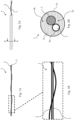
- Figure 1A and 1B show an exemplary embodiment of a composite yarn 1 according to the present invention.
- the composite yarn 1 comprises an electrically conductive yarn 2 and an electrically resistive yarn 3 (that are visible more clearly in the enlarged view shown in figure 1B ).
- the electrically conductive yarn 2 and the electrically resistive yarn 3 are coupled together, by twisting.
- the electrically conductive yarn 2 is electrically insulated from the electrically resistive yarn 3, for example by an electrically insulating coating 2a provided on the surface of the electrically conductive yarn 2.
- the electrically conductive yarn 2 is preferably an insulated metal wire, for example a magnet wire.
- a magnet wire also called “enameled wire” is a metal wire (for example made of copper or aluminum) coated with a very thin layer of insulation. Magnet wires are commercially available and are typically used in the construction of transformers, inductors, motors, speakers, hard disk head actuators, electromagnets, and other applications that require tight coils of insulated wire.
- the electrically conductive yarn 2 has an electrical resistance per unit of length Rc less than 200 ⁇ /m, preferably less than 50 ⁇ /m, for example about 10 ⁇ /m.
- the cross section and the electrical resistivity of the electrically conductive yarn 2 are chosen to obtain a meter of electrically conductive yarn 2 having an electrical resistance less than 200 ⁇ , more preferably less than 50 ⁇ , for example about 10 ⁇ .
- the electrically conductive yarn 2 may be made of a material having electrical resistivity less than 10 -6 ⁇ m, more preferably less than 10 -7 ⁇ m (e.g. silver, copper, gold, aluminum, platinum, iron may be suitable materials for the electrically conductive yarn 2).
- the electrically resistive yarn 3 has an electrical resistance per unit of length Rr comprised between 10 k ⁇ /m and 10 M ⁇ /m, preferably comprised between 50 k ⁇ /m and 500 k ⁇ /m, for example about 200 k ⁇ /m.
- the cross section and the electrical resistivity of the electrically resistive yarn 3 are chosen to obtain a meter of electrically resistive yarn 3 having an electrical resistance comprised between 10 k ⁇ and 10 M ⁇ , more preferably comprised between 50 k ⁇ and 500 k ⁇ , for example about 200 k ⁇ .
- the electrically resistive yarn 3 has electrical resistivity comprised between 10 -6 ⁇ m and 10 3 ⁇ m, more preferably between 10 -4 ⁇ m and 10 -1 ⁇ m.
- the electrically resistive yarn 3 is a plastic yarn (e.g. nylon) filled with electrically conductive elements (e.g. electrically conductive carbon). More preferably, the electrically resistive yarn 3 may be a 80-denier nylon 6,6 having electrically conductive carbon suffused into its surface.
- a suitable electrically resistive yarn 3 may be the electrically resistive yarn available with the commercial name RESISTAT ⁇ F901, MERGE R080 that is a 80-denier nylon 6,6 monofilament which has electrically conductive carbon suffused into the surface.
- This particular resistive yarn has a round cross section with a coating thickness of about 1 ⁇ m, and a linear mass density of about 84 denier.
- the electrical resistance of this resistive yarn is about 0.8 10 5 ⁇ per centimeter (i.e. about 80 k ⁇ /m).
- the electrical resistance per unit of length of the electrically conductive yarn 2 is at least two order of magnitude less than the electrical resistance per unit of length of the electrically resistive yarn 3.
- the ratio Rr/Rc between the values of electrical resistance per unit of length of the electrically resistive yarn 3 and the electrically conductive yarn 2 is in range of 100 to 1000000, more preferably 1000 to 100000.
- some embodiments of the present invention may provide that the composite yarn 1 comprises a sheath 1b made of an electrically non-conductive material.
- the electrically conductive yarn 2 and the electrically resistive yarn 3 form a sensing core 1a covered by the sheath 1b.
- the sheath 1b may be formed for example by an electrically non-conductive yarn having an electrical resistance per unit of length Rn greater than 100 M ⁇ /m, more preferably greater than 1 G ⁇ /m.
- the sheath 1b of the composite yarn 1 comprises staple fibers 4 made of an electrically non-conductive material, preferably having electrical resistivity greater than 10 3 ⁇ m, more preferably greater than 10 6 ⁇ m.
- the sensing core 1a is preferably core-spun with the staple fibers 4 of the sheath 1b. Some embodiments may provide that the sensing core 1a is embroidered around with the staple fibers 4 of the sheath 1b, or covered by other sheathing processes known in the art.
- the staple fibers 4 are preferably natural fibers such as cotton, wool, silk and the like. Some embodiments may provide that the sheath 1b of the composite yarn 1 is provided with a dyeing 1c, for example an indigo dye.
- the composite yarn 1 can be used for producing a capacitive touch sensor 10 able to be embedded in a fabric.
- the electrically conductive elongated element 2 and the electrically resistive elongated element 3 are configured to be electrically connected to a detection device 5.
- the detection device 5 is configured to evaluate the capacitance values CR, CC of the electrically resistive elongated element 3 and of the electrically conductive elongated element 2.
- the detection device is configured to calculate the ratio CR/CC between the capacitance values CR, CC of the electrically resistive elongated element 3 and of the electrically conductive elongated element 2, and to provide an output signal SOUT indicative of the location of a touch event along the composite elongated element 1 in function of the ratio CR/CC.
- a touch sensor according to the invention refers to yarns and composite yarns as above disclosed, however the teaching of the description can be applied to a touch sensor having generic elongated elements in the place of yarns.
- the touch sensor 10 comprises at least one composite yarn 1, and a detection device 5 configured to evaluate the capacitance value CR of the electrically resistive yarn 3 and the capacitance value CC of the electrically conductive yarn 2.
- the capacitance values CR and CC of the electrically conductive and resistive yarns 2, 3 may be evaluated for example by measuring the charging time, or the oscillation frequency of an oscillator, or by other measuring technics known in the art.
- the detection device 5 comprises a front-end circuit 6 to which the electrically conductive and resistive yarns 2, 3 are connected.
- the front-end circuit 6 may comprise at least one oscillator (e.g. a Colpitts oscillator).
- the electrically conductive and resistive yarns 2, 3 are connected selectively to the oscillator that has (in absence of a touch event) a predetermined oscillation frequency.
- a change of the capacitance values CR and CC of the electrically conductive and resistive yarns 2, 3 is detected as a change of the oscillation frequency of the oscillator.
- the capacitance values CR and CC of the electrically conductive and resistive yarns 2, 3 can be calculated.
- the detection device 5 comprises a microcontroller 7 connected to the front-end circuit 6, and configured to calculate the capacitance values CR and CC of the electrically conductive and resistive yarns 2, 3 on the basis of the oscillation frequency of the oscillator.
- the front-end circuit 6 comprises a sending terminal connected to a microcontroller 7 that sends a reference signal (e.g. a Boolean signal) to the sending terminal of the front-end circuit 6.
- a reference signal e.g. a Boolean signal
- the front-end circuit 6 comprises a returning terminal that replicates the reference signal with a delay which is a function of the charging time of the electrically conductive and resistive yarns 2, 3.
- the capacitance values CR and CC of the electrically conductive and resistive yarns 2, 3 can be calculated on the basis of the delay evaluated.
- the composite yarn 1 is electrically connected at a read-out point, preferably at one of its ends, to the detection device 5.
- one end of the electrically resistive yarn 3 is electrically connected to the detection device 5.
- the respective end of the electrically conductive yarn 2 is electrically connected to the detection device 5.
- the capacitance value CC of the electrically conductive yarn 2 changes in response to touch events, irrespective of the position on which the touch events occurred along the composite yarn 1 with respect to the read-out point.
- the capacitance value CC indicates if a touch event occurs and how much is strong the capacitive coupling between the electrically conductive yarn 2 and an object (e.g. a finger of a user) touching the composite yarn 1.
- the capacitance value CR of the electrically resistive yarn 3 changes in response to touch events and in function of the position on which the touch events occurred along the composite yarn 1 with respect to the read-out point. In other words, if an object (e.g. a finger of a user) touches the composite yarn 1 in different positions along its length, the capacitance value CR changes in function of the position on which the touch events occurred along the composite yarn 1.
- an object e.g. a finger of a user
- the electrically resistive yarn 3 can be represented with a lumped model of a capacitor in series with a resistor having a resistance value depending on the position of the touch event (i.e. the position on which the parasitic capacitance of the object is applied to the electrically resistive yarn 3).
- the value of the electrical resistivity is so small that the dependency of the capacitive value CC from the position on which the touch event occurred is negligible.
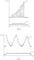
- figure 4 shows a graph in the time domain of the capacitance values CR and CC of a composite yarn 1 according to a particular embodiment of the present invention in response to a sequence of touch events performed by the finger of a user at a plurality of positions along the length of the composite yarn 1.
- Figure 5 shows the same graph of figure 4 , when the finger of the user continuously swipes along the length of the composite yarn 1.
- a touch event far from the detection device 5 will be detected with a low capacitance value CR.
- a high capacitance value CR will be detected.
- the graphs shown in figures 4 and 5 was obtained by touching a 10 cm composite yarn 1 comprising an insulating copper wire 2 (magnet wire) having a cross section with diameter of about 35 ⁇ m twisted with an electrically resistive yarn 3 available with the commercial name RESISTAT ⁇ F901, MERGE R080 to form a sensing core 1a core-spun with a sheath 1b of cotton fibers.
- a 10 cm composite yarn 1 comprising an insulating copper wire 2 (magnet wire) having a cross section with diameter of about 35 ⁇ m twisted with an electrically resistive yarn 3 available with the commercial name RESISTAT ⁇ F901, MERGE R080 to form a sensing core 1a core-spun with a sheath 1b of cotton fibers.
- the capacitance value CR of the electrically resistive yarn 3 changes also in function of the capacitive coupling between the electrically resistive yarn 3 and the object touching the composite yarn 1.
- the capacitance value CR cannot be evaluated the position of the touch event without taking into account the capacitive coupling between the object and the electrically resistive yarn 3.
- the capacitive coupling between the electrically resistive yarn 3 and the object touching the composite yarn 1 changes (for example in the case of different users that have different parasitic capacitance values)
- the capacitance values CR of the electrically resistive yarn 3 evaluated in response to touch events on the same position along the composite yarn will be different.
- the detection device 5 is advantageously configured to calculate the ratio CR/CC between the capacitance values CR and CC of the electrically resistive yarn 3 and of the electrically conductive yarn 2.
- the ratio CR/CC is indicative of the location of a touch event along the composite yarn 1 with a negligible dependency of the capacitive coupling between the object touching the composite yarn 1 and the electrically resistive and conductive yarns 2, 3.
- the value of the ratio CR/CC is indicative of the location of a touch event along the composite yarn 1 irrespectively of how strong is the capacitive coupling between the object touching the composite yarn 1 and the electrically resistive and conductive yarns 2, 3.
- the detection device 5 comprises a microcontroller 7 configured to calculate the ratio CR/CC of the evaluated capacitance values CR, CC.
- the detection device 5 is configured to provide an output signal SOUT in function of the ratio CR/CC that is indicative of the location of a touch event along the composite yarn 1.
- the output signal SOUT may return the value of the ratio CR/CC eventually multiplied by a coefficient k chosen for example in function of the length of the composite yarn 1.
- the output signal SOUT is preferably updated with a predetermined cadency having a refresh period (e.g. some milliseconds) during which the capacitance values CR and CC are reevaluated for updating the ratio CR/CC.
- the touch sensor 10 shown in figure 3 may be used for detecting not only the direction of a swipe, but also on which region of the composite yarn 1 a swipe occurred. Touch events may be detected with precision and reliability along a sensing region of a fabric on which the composite yarn 1 is coupled. In other words, with a single composite yarn 1, the touch sensor 10 of the present invention may distinguish different swipes in different regions of a fabric.
- the composite yarn 1 (or in general the composite elongated element 1) may be coupled to a fabric (or to a generic support layer) by sewing, by knitting, by weaving, or by any other coupling technique known in the art.
- the composite elongated element 1 comprises a trace of electrically resistive material (as electrically resistive elongated element 3) and/or a trace of electrically conductive material (as electrically conductive elongated element 2) arranged along a substantially linear path.
- Such traces may be produced for example including a biopolymer (such as microbial cellulose, microbial collagen, cellulose/chitin copolymer, microbial silk, or a mixture thereof) with electrically conductive material (such as carbonaceous material, preferably selected from the group consisting of activated carbon, high surface area carbon, graphene, graphite, activated charcoal, carbon nanotubes, carbon nanofibers, activated carbon fibers, graphite fibers, graphite nanofibers, carbon black and mixtures thereof).
- a biopolymer such as microbial cellulose, microbial collagen, cellulose/chitin copolymer, microbial silk, or a mixture thereof
- electrically conductive material such as carbonaceous material, preferably selected from the group consisting of activated carbon, high surface area carbon, graphene, graphite, activated charcoal, carbon nanotubes, carbon nanofibers, activated carbon fibers, graphite fibers, graphite nanofibers, carbon black and mixtures thereof.
- electrically conductive material may be provided to the biopolymer (e.g., to a biopolymer layer or trace) by printing (e.g., screen printing and/or digital printing), or by localized impregnation.
- a culture containing biopolymer-producing microorganisms comprises electrically conductive material.
- a support layer may be contacted with a culture including biopolymer-producing microorganisms and an electrically conductive material.
- the microorganisms may be cultured to produce a biopolymer including electrically conductive material, so that the support layer is provided with a trace of electrically resistive material made of biopolymer comprising electrically conductive material.
- the touch sensor 10 comprises a plurality of composite yarns 1, for example coupled to a fabric to provide a plurality of sensing regions.
- the detection device 5 is configured to calculate the ratio CR/CC between the capacitance values of the electrically resistive yarn 2 and of the electrically conductive yarn 3 for each composite yarn 1.
- the output signal provided by the detection device is indicative of the location of a touch event along each composite yarn 1 of the plurality of composite yarns.
- the composite yarns 1 are arranged substantially parallel to each other. This arrangement allows to provide a touch pad able to detect a touch event and the location of the touch event on the sensing region on which the composite yarns 1 are arranged, and wherein the composite yarns 1 may be arranged only in one direction (vertical or horizontal) and can be connected to the detection device 5 only on one side of the touch pad.
- figure 6 shows an embodiment of the touch sensor 10 according to the present invention wherein a plurality of composite yarns 1 are woven on a fabric 9.
- the fabric 9 is preferably a denim fabric or in general a woven fabric.
- the embodiment of figure 6 provides for example that the weft of the fabric 9 comprises a plurality of composite yarns 1 arranged between other weft yarns 9a made of textile material.
- the warp of the fabric 9 comprises a plurality of composite yarns 1 arranged between other warp yarns 9b made of textile material.
- Some embodiments may provide that all the yarns of the warp or of weft are composite yarns 1 while remaining in the scope of protection of the present invention.
- the touch sensor 10 may comprise a plurality of composite yarns 1 that are at least part of the warp or of the weft of a woven fabric 9.
- the electrically resistive yarns 2 and of the electrically conductive yarns 3 of the composite yarns 1 are connected to the front-end circuit 6 of the detection device 5, so that the microcontroller 7 of the detection device 5 can calculate the ratio CR/CC between the capacitance values CR and CC of the electrically resistive yarn 2 and of the electrically conductive yarn 3 for each composite yarn 1.
- the output signal SOUT provided by the detection device 5 is indicative of the location of a touch event along each composite yarn 1 of the plurality of composite yarns 1.
- the output signal SOUT may return a set of values of a scanning sequence, wherein each value of the scanning sequence is the ratio CR/CC (eventually multiplied by a coefficient k chosen for example in function of the length of the composite yarn 1) of each composite yarn 1.
- the values of the ratio CR/CC of each scanning sequence are provided with a predetermined order (for example from the upper to the lower or vice versa).
- the output signal SOUT is preferably updated with a predetermined cadency having a refresh period during which the capacitance values CR and CC of each composite yarn 1 are reevaluated for updating the sequence of the values of the ratio CR/CC.
- the touch sensor 10 of the present invention may be used for controlling or sending a control command to an external device 20.
- the detection device 5 is connected to a communication module 8 configured to transmit the output signal SOUT to an external device 20.
- the communication module 8 is a wireless communication module (e.g. Bluetooth module, WiFi module, Infrared module, and the like).
- the composite yarn(s) 1 of the touch sensor 10 may be coupled to a fabric 9 for producing a garment (preferably a jacket or a pair of pants) having a sensing region that allows the wearer to control an external device 20 (e.g. a smartphone, a music player or the like) in a simple and reliable way.
- a garment preferably a jacket or a pair of pants
- an external device 20 e.g. a smartphone, a music player or the like
- the touch sensor 10 may be coupled to a fabric 9 for lining a seating furniture (preferably a sofa or an armchair) on a sensing region (e.g. on the arms of the seating furniture) for allowing the sitting user to control an external device 20 (e.g. a smart TV, a stereo or the like) easily.
- a seating furniture preferably a sofa or an armchair
- a sensing region e.g. on the arms of the seating furniture
- an external device 20 e.g. a smart TV, a stereo or the like
- a method for detecting the location of a touch event on a fabric comprises the following steps:
- the method comprises a step of detecting a touch event, preferably in function of the capacitance value CC of the electrically conductive yarn 2 evaluated in the step (b).
- the touch event may be detected for example by comparing the capacitance value CC evaluated in the step (b) with a threshold value.
- the steps (c) and (d) are carried out when a touch event is detected (in absence of a detected touch event the output signal SOUT is kept to a predetermined value indicative of absence of touch event).
Landscapes
- Engineering & Computer Science (AREA)
- General Engineering & Computer Science (AREA)
- Theoretical Computer Science (AREA)
- Textile Engineering (AREA)
- Human Computer Interaction (AREA)
- Physics & Mathematics (AREA)
- General Physics & Mathematics (AREA)
- Mechanical Engineering (AREA)
- Computer Networks & Wireless Communication (AREA)
- Quality & Reliability (AREA)
- Yarns And Mechanical Finishing Of Yarns Or Ropes (AREA)
- Woven Fabrics (AREA)
Description
- The present invention relates to the field of the capacitive sensing. In particular, the present invention relates to a composite yarn for a fabric implementing a touch sensor.
- Capacitive touch sensors comprise a plurality of electrically conductive wires, electrically insulated from each other, and arranged to form a grid.
- Capacitive touch sensors may employ the "self-capacitance sensing" technique wherein each sensing wire is connected to a controller configured to evaluate the capacitance value of each sensing wire, i.e. independently to each other. In these capacitive touch sensors, the controller is configured to detect the change of value in the capacitance of each sensing wire due to the parasitic capacitance provided by an object (e.g. a finger) touching the sensing wire. The position of a touch event is determined by the controller by detecting which sensing wires (i.e. which rows and columns) of the capacitive grid are touched, so that the position of the touch is determined as X, Y coordinates on the capacitive grid.
- Some capacitive touch sensors employ the "mutual capacitance sensing" technique wherein the controller is configured to evaluate sequentially the mutual capacitance value at each intersection of sensing wires. In other words, the controller is configured to evaluate the capacitance value of each capacitor formed between sensing wires for each row and each column of the capacitive grid. A touch of an object (e.g. a finger) on the capacitive grid is detected as a change of value in the mutual capacitance.
- Capacitive touch sensors embedded in a fabric are known. For example,
US2016048235A1 discloses a fabric implementing a capacitive touch sensing comprising a plurality of electrically conductive wires, electrically insulated from each other, and arranged to form a grid. - Each wire is connected to a controller configured to evaluate the capacitance value of each wire (i.e. using the "self-capacitance sensing"). The controller detects the position of a touch event by detecting which horizontal wire and which vertical wire is touched, by detecting changes in capacitance of each respective wire of the capacitive grid. The controller uses the intersection of the crossing wires that are touched to determine the position of the touch event on the capacitive grid, so that the position of the touch is determined as X, Y coordinates on the capacitive grid.
- The capacitive grid can be embedded in a fabric by using the electrically conductive wires as weft yarns and warp yarns. However, each electrically conductive wire of the capacitive grid (vertical and horizontal wires) have to be electrically connected to a sensing circuit by means of electrical contacts arranged along both the vertical side and the horizontal side of the capacitive grid. The routing of the electrical connections between the capacitive grid and the sensing circuit may be very complex when the capacitive grid has a great number of electrically conductive wires.
- Furthermore, in case of a touch sensor having a substantially rectangular form (i.e. having a number of horizontal wires different with respect to the number of vertical wires) or provided with electrically conductive wires arranged parallel along only one direction (e.g. in case of a swipe sensor), the arrangement of the electrical contacts and the routing of the electrical connections between the conductive wires and the sensing circuit may be very difficult to be designed, making the production of the touch sensor complex and expensive and in some cases causing a stiffening of the touch sensor structure.
- Document
WO 2004/003273 A2 discloses a coaxial conductive yarn structure 100 comprising an inner conductive yarn 102 extending in a first direction and having a plurality of first conductive strands being twisted together; an outer conductive yarn 106 having a plurality of second conductive strands 108 being twisted together, the outer conductive yarn 1006 being wrapped around the inner conductive yarn 102 in a second direction transverse to the first direction and substantially covering the inner conductive yarn 102; and at least one insulating layer 104 for electrically isolating the inner and outer conductive yarns from each other. - The above structure is described as able to reduce signal crosstalk between adjacent lines in woven electrical networks, improving signal integrity in fabric-based electrical circuits.
- Document
EP 1176610 A1 discloses a thin wire for production of a fiber material. In particular, a woven or nonwoven fabric comprises a metal wire which is coated with an organic-based protective, electrically conductive layer. A method of production of an electrically conductive fabric is also disclosed in which, first a compound thread is produced by covering the wire with textile fibers, and subsequently such a thread is used to produce of the fabric. - Document
WO2016154561 A1 describes conductive thread for interactive textiles. An interactive textile includes a grid of conductive thread woven into the interactive textile to form a capacitive touch sensor that is configured to detect touch-input. The interactive textile can process the touch-input to generate touch data that is useable to initiate functionality at various remote devices that are wirelessly coupled to the interactive textile. The interactive textile disclosed may aid users in controlling volume on a stereo, pausing a movie playing on a television, or selecting a webpage on a desktop computer. - Document
WO2014092781 A1 discloses a flexible electrically functional woven or nonwoven fabric comprising a plurality of textile fibers; and at least one flexible electrically functional fiber capable of at least one of providing energy storage and/or electrical interconnection to an electrical component. The fabric may comprise a microprocessor, a power source, a switch, a transducer, a light emitting device, a data storage device, a transmitter, a receiver or any combination thereof. - An object of the present invention is to overcome the drawbacks of the prior art cited above and to provide a composite yarn that allows to produce a touch sensor having a simple routing of the electrical connections.
- A further object of the present invention is to provide a touch sensor and a method for detecting the location of touch event on a support layer (for example a fabric) able to detect the touch event in a precise and reliable way.
- These and other objects are achieved by the present invention by a composite yarn, a touch sensor, and a method for detecting a touch event according to the independent claims. Preferred aspects of the invention are recited in the dependent claims.
- In particular, according to the present invention, the composite yarn comprises an electrically conductive yarn and an electrically resistive yarn, wherein the electrically conductive yarn is coupled to the electrically resistive yarn, and wherein the electrically conductive yarn is electrically insulated from the electrically resistive yarn.
- According to the present invention, the electrical resistance per unit of length of the electrically conductive yarn is less than 200 Ω/m.
- According to the present invention, the electrical resistance per unit of length of the electrically resistive yarn is comprised between 10 kΩ/m and 10 MΩ/m. The electrically resistive yarn has a capacitance value that changes when an object touches it (a parasitic capacitance of the object is coupled to the electrically resistive yarn). The change in capacitance value of the resistive yarn is function of two main aspects: the parasitic capacitive coupling between the electrically resistive yarn and the object touching it, and the location on which the touching event occurred along the length of the resistive yarn with respect to the read-out point on which the capacitance value of the electrically resistive yarn is evaluated (i.e. with respect to the point on which the electrically resistive yarn is electrically connected to a detection device).
- According to an aspect of the present invention, the electrically resistive yarn has a capacitance value that changes in response to a touch event; said change in value is a function of the location on which the touching event occurred along the length of the electrically resistive yarn with respect to the read-out point. In other words, when a touch event occurs on a point of the electrically resistive yarn, the capacitance value of the electrically resistive yarn evaluated at the read-out point (for example at an end of the electrically resistive yarn) changes in function of the length of the electrically resistive yarn comprised between the read-out point and the point on which the touch event occurred.
- According to an aspect of the present invention, when an object touches the electrically conductive yarn, the change in capacitance value depends substantially only from the capacitive coupling between the electrically conductive yarn and the object touching it.
- According to an aspect of the present invention, the electrically conductive yarn has a capacitance value that changes in response to a touch event; said change in value is substantially independent from the location on which the touching event occurred along its length.
- Thanks to this aspect, a single composite yarn may be used for detecting the location of a touch event along its length by calculating the ratio between the capacitance values of the electrically resistive yarn and of the electrically conductive yarn. In other words, the capacitance value of the electrically resistive yarn evaluated with respect to the capacitance value of the electrically conductive yarn provides a value indicative of the position of a touch event along the length of the composite yarn independently from the capacitive coupling between the composite yarn and the object touching it.
- According to the present invention, the electrically conductive yarn and the electrically resistive yarn are coupled along their length. In other words, the electrically conductive yarn and the electrically resistive yarn are arranged adjacent, so that any cross-section of the composite yarn comprises part of both the electrically conductive yarn and electrically resistive yarn.
- According to the present invention, the electrically conductive yarn and the electrically resistive yarn are coupled by twisting.
- Advantageously, the electrically conductive yarn and the electrically resistive yarn form a sensing core of the composite yarn. Preferably, the composite yarn further comprises a sheath made of an electrically non-conductive material covering said sensing core. For example, the sheath may comprise an electrically non-conductive yarn having an electrical resistance per unit of length greater than 100 MΩ/m, more preferably greater than 1 GΩ/m.
- According to an aspect of the present invention, the electrical resistivity of the electrically non-conductive material is greater than 103 Ωm.
- Preferably, the sheath comprises staple fibers made of the electrically non-conductive material, the sensing core being preferably core-spun with the staple fibers. More preferably the staple fibers are natural fibers (e.g. cotton).
- According to the present invention, the electrically resistive yarn is a plastic yarn filled with electrically conductive elements.
- Preferably the electrically conductive yarn is an insulated metal wire (e.g. a copper magnet wire).
- According to an aspect of the present invention, the electrical resistance per unit of length of the electrically conductive yarn is at least two order of magnitude less than the electrical resistance per unit of length of the electrically resistive yarn. Preferably, the ratio between the values of electrical resistance per unit of length of the electrically resistive yarn and the electrically conductive yarn is in range of 100 to 1000000, more preferably 1000 to 100000.
- A further object of the present invention is a capacitive touch sensor comprising the composite yarn according to the present invention. Some embodiments may provide that the capacitive touch tensor comprises at least one composite elongated element comprising a trace of electrically resistive material (as electrically resistive elongated element) and/or a trace of electrically conductive material (as electrically conductive elongated element arranged along a substantially linear path.
- In other words, according to the present invention, the electrical resistance per unit of length of the electrically conductive elongated element is less than 200 Ω/m.
- According to the present invention, the electrical resistance per unit of length of the electrically resistive elongated element is comprised between 10 kΩ/m and 10 MΩ/m.
- According to an aspect of the present invention, the electrical resistance per unit of length of the electrically conductive elongated element is at least two order of magnitude less than the electrical resistance per unit of length of the electrically resistive elongated element. Preferably, the ratio between the values of electrical resistance per unit of length of the electrically resistive elongated element and the electrically conductive elongated element is in range of 100 to 1000000, more preferably 1000 to 100000.
- The electrical resistance per unit of length of an elongated element, is measured by following the standard AATCC Test Method 84-2005 or AATCC Test Method 84-2011.
- The capacitive touch sensor has a detection device configured to evaluate the capacitance values of the electrically resistive elongated element and of the electrically conductive elongated element of the composite elongated element (i.e. by using the self-capacitance sensing).
- According to an aspect of the present invention, the detection device is configured to calculate the ratio between said capacitance values of the electrically resistive elongated element and of the electrically conductive elongated element and to provide an output signal indicative of the location of a touch event along the composite elongated element in function of this ratio.
- Thanks to this aspect, only one composite elongated element may be used for detecting the location of a touch event along a determined direction (the direction along which the composite elongated element is arranged). For example, a touch sensor comprising only one composite yarn of the present invention may be used as a swipe sensor with only two electrical contacts for connecting the electrically conductive and resistive elongated elements to the detection device.
- According to an aspect of the present invention, the touch sensor comprises a plurality of composite elongated elements, wherein the detection device is configured to calculate the ratio between the capacitance values of the electrically resistive elongated element and of the electrically conductive elongated element for each composite elongated element and to provide an output signal indicative of the location of a touch event along each composite yarn of the plurality of composite elongated elements.
- Preferably, the composite elongated elements are arranged substantially parallel to each other.
- Thanks to this aspect, the composite elongated elements of the touch sensor can be electrically connected to the detection device along only a side of the touch sensor. In other words, the touch sensor allows to detect the location of a touch event on a X-Y reference plane by arranging a plurality of composite elongated elements parallel to each other along only one of the directions X or Y.
- According to an aspect of the present invention, the composite elongated element or the plurality of composite elongated elements may be coupled to a support layer, preferably a fabric. Thanks to this aspect, the touch sensor may be embedded easily on a fabric.
- Preferably, some embodiments may provide that the touch sensor is embedded in a woven fabric. More preferably, these embodiments provide that one or more composite yarns may be at least part of the warp or of the weft of the woven fabric. Some embodiments of the present invention may provide that the detection device is connected to a communication module configured to transmit the output signal to an external device (e.g. a smartphone).
- A further object of the present invention is a method for detecting the location of a touch event on a support layer comprising the following steps:
- (a) providing a support layer comprising at least one composite elongated element comprising an electrically conductive elongated element and an electrically resistive elongated element, wherein the electrically conductive elongated element is coupled to the electrically resistive elongated element, and wherein the electrically conductive elongated element is electrically insulated from the electrically resistive elongated element;
- (b) evaluating the capacitance values of the electrically resistive elongated element and of the electrically conductive elongated element of the at least one composite elongated element;
- (c) calculating the ratio between the capacitance value of the electrically resistive elongated element and the capacitance value of the electrically conductive elongated element evaluated in the step (b);
- (d) providing an output signal indicative of the location of said detected touch event in function of the ratio calculated in the step (c).
- According to the present invention, the support layer is a fabric, wherein the composite elongated element is the composite yarn according to the present invention.
- The invention will now be described in greater detail, by way of example, with reference to the accompanying non limiting drawings. It is emphasized that, according to common practice, the various features of the drawing are not necessarily to scale. On the contrary, the dimensions of the various features are arbitrarily expanded or reduced for clarity. Like numerals denote like features throughout the specification and the drawings in which:
-
Figure 1A schematically shows a perspective view of a composite yarn according to an embodiment of the present invention; -
Figure 1B is an expanded view showing a portion of the composite yarn shown inFigure 1 ; -
Figure 2A schematically shows a perspective view of a composite yarn according to a further embodiment of the present invention; -
Figure 2B is a cross section along the cutting plane A-A of the composite yarn shown inFigure 2A ; -
Figure 3 schematically shows a perspective view of a touch sensor according to an embodiment of the present invention; -
Figures 4 and 5 show two graphs in the time domain of the capacitance values of a composite yarn according to a particular embodiment of the present invention during two different types of touch events; -
Figure 6 schematically shows a perspective view of a touch sensor according to an embodiment of the present invention. -
Figure 1A and 1B show an exemplary embodiment of acomposite yarn 1 according to the present invention. Thecomposite yarn 1 comprises an electricallyconductive yarn 2 and an electrically resistive yarn 3 (that are visible more clearly in the enlarged view shown infigure 1B ). - The electrically
conductive yarn 2 and the electricallyresistive yarn 3 are coupled together, by twisting. - The electrically
conductive yarn 2 is electrically insulated from the electricallyresistive yarn 3, for example by an electrically insulatingcoating 2a provided on the surface of the electricallyconductive yarn 2. - The electrically
conductive yarn 2 is preferably an insulated metal wire, for example a magnet wire. A magnet wire, also called "enameled wire" is a metal wire (for example made of copper or aluminum) coated with a very thin layer of insulation. Magnet wires are commercially available and are typically used in the construction of transformers, inductors, motors, speakers, hard disk head actuators, electromagnets, and other applications that require tight coils of insulated wire. - The electrically
conductive yarn 2 has an electrical resistance per unit of length Rc less than 200 Ω/m, preferably less than 50 Ω/m, for example about 10 Ω/m. In other words, the cross section and the electrical resistivity of the electricallyconductive yarn 2 are chosen to obtain a meter of electricallyconductive yarn 2 having an electrical resistance less than 200 Ω, more preferably less than 50 Ω, for example about 10 Ω. - For example, the electrically
conductive yarn 2 may be made of a material having electrical resistivity less than 10-6 Ωm, more preferably less than 10-7 Ωm (e.g. silver, copper, gold, aluminum, platinum, iron may be suitable materials for the electrically conductive yarn 2). - The electrically
resistive yarn 3 has an electrical resistance per unit of length Rr comprised between 10 kΩ/m and 10 MΩ/m, preferably comprised between 50 kΩ/m and 500 kΩ/m, for example about 200 kΩ/m. In other words, the cross section and the electrical resistivity of the electricallyresistive yarn 3 are chosen to obtain a meter of electricallyresistive yarn 3 having an electrical resistance comprised between 10 kΩ and 10 MΩ, more preferably comprised between 50 kΩ and 500 kΩ, for example about 200 kΩ. - For example, the electrically
resistive yarn 3 has electrical resistivity comprised between 10-6 Ωm and 103 Ωm, more preferably between 10-4 Ωm and 10-1 Ωm. - The electrically
resistive yarn 3 is a plastic yarn (e.g. nylon) filled with electrically conductive elements (e.g. electrically conductive carbon). More preferably, the electricallyresistive yarn 3 may be a 80-denier nylon - For example, a suitable electrically
resistive yarn 3 may be the electrically resistive yarn available with the commercial name RESISTAT© F901, MERGE R080 that is a 80-denier nylon - According to an aspect of the present invention, the electrical resistance per unit of length of the electrically
conductive yarn 2 is at least two order of magnitude less than the electrical resistance per unit of length of the electricallyresistive yarn 3. - Preferably, the ratio Rr/Rc between the values of electrical resistance per unit of length of the electrically
resistive yarn 3 and the electricallyconductive yarn 2 is in range of 100 to 1000000, more preferably 1000 to 100000. - With respect to
figures 2A and 2B , some embodiments of the present invention may provide that thecomposite yarn 1 comprises a sheath 1b made of an electrically non-conductive material. In these embodiments, the electricallyconductive yarn 2 and the electricallyresistive yarn 3 form a sensing core 1a covered by the sheath 1b. - The sheath 1b may be formed for example by an electrically non-conductive yarn having an electrical resistance per unit of length Rn greater than 100 MΩ/m, more preferably greater than 1 GΩ/m.
- According to an aspect of the present invention, the sheath 1b of the
composite yarn 1 comprisesstaple fibers 4 made of an electrically non-conductive material, preferably having electrical resistivity greater than 103 Ωm, more preferably greater than 106 Ωm. - The sensing core 1a is preferably core-spun with the
staple fibers 4 of the sheath 1b. Some embodiments may provide that the sensing core 1a is embroidered around with thestaple fibers 4 of the sheath 1b, or covered by other sheathing processes known in the art. - The
staple fibers 4 are preferably natural fibers such as cotton, wool, silk and the like. Some embodiments may provide that the sheath 1b of thecomposite yarn 1 is provided with a dyeing 1c, for example an indigo dye. - The
composite yarn 1 can be used for producing acapacitive touch sensor 10 able to be embedded in a fabric. - The electrically conductive
elongated element 2 and the electrically resistiveelongated element 3 are configured to be electrically connected to a detection device 5. - The detection device 5 is configured to evaluate the capacitance values CR, CC of the electrically resistive
elongated element 3 and of the electrically conductiveelongated element 2. The detection device is configured to calculate the ratio CR/CC between the capacitance values CR, CC of the electrically resistiveelongated element 3 and of the electrically conductiveelongated element 2, and to provide an output signal SOUT indicative of the location of a touch event along the compositeelongated element 1 in function of the ratio CR/CC. - For the sake of simplicity, the following description of a touch sensor according to the invention refers to yarns and composite yarns as above disclosed, however the teaching of the description can be applied to a touch sensor having generic elongated elements in the place of yarns.
- In particular, with respect to
figure 3 , thetouch sensor 10 comprises at least onecomposite yarn 1, and a detection device 5 configured to evaluate the capacitance value CR of the electricallyresistive yarn 3 and the capacitance value CC of the electricallyconductive yarn 2. - The capacitance values CR and CC of the electrically conductive and
resistive yarns - Some embodiments may provide that the detection device 5 comprises a front-
end circuit 6 to which the electrically conductive andresistive yarns end circuit 6 may comprise at least one oscillator (e.g. a Colpitts oscillator). The electrically conductive andresistive yarns - A change of the capacitance values CR and CC of the electrically conductive and
resistive yarns resistive yarns - Preferably, the detection device 5 comprises a
microcontroller 7 connected to the front-end circuit 6, and configured to calculate the capacitance values CR and CC of the electrically conductive andresistive yarns - For example, the front-
end circuit 6 comprises a sending terminal connected to amicrocontroller 7 that sends a reference signal (e.g. a Boolean signal) to the sending terminal of the front-end circuit 6. - The front-
end circuit 6 comprises a returning terminal that replicates the reference signal with a delay which is a function of the charging time of the electrically conductive andresistive yarns resistive yarns - The
composite yarn 1 is electrically connected at a read-out point, preferably at one of its ends, to the detection device 5. In particular, one end of the electricallyresistive yarn 3 is electrically connected to the detection device 5. Analogously, the respective end of the electricallyconductive yarn 2 is electrically connected to the detection device 5. - As shown in
figures 4 and 5 , the capacitance value CC of the electricallyconductive yarn 2 changes in response to touch events, irrespective of the position on which the touch events occurred along thecomposite yarn 1 with respect to the read-out point. In other words, the capacitance value CC indicates if a touch event occurs and how much is strong the capacitive coupling between the electricallyconductive yarn 2 and an object (e.g. a finger of a user) touching thecomposite yarn 1. - The capacitance value CR of the electrically
resistive yarn 3 changes in response to touch events and in function of the position on which the touch events occurred along thecomposite yarn 1 with respect to the read-out point. In other words, if an object (e.g. a finger of a user) touches thecomposite yarn 1 in different positions along its length, the capacitance value CR changes in function of the position on which the touch events occurred along thecomposite yarn 1. - Basically, the electrically
resistive yarn 3 can be represented with a lumped model of a capacitor in series with a resistor having a resistance value depending on the position of the touch event (i.e. the position on which the parasitic capacitance of the object is applied to the electrically resistive yarn 3). In the case of the electricallyconductive yarn 2, the value of the electrical resistivity is so small that the dependency of the capacitive value CC from the position on which the touch event occurred is negligible. - In particular,
figure 4 shows a graph in the time domain of the capacitance values CR and CC of acomposite yarn 1 according to a particular embodiment of the present invention in response to a sequence of touch events performed by the finger of a user at a plurality of positions along the length of thecomposite yarn 1. -
Figure 5 shows the same graph offigure 4 , when the finger of the user continuously swipes along the length of thecomposite yarn 1. A touch event far from the detection device 5 will be detected with a low capacitance value CR. When the touch event is performed near the detection device 5 (i.e. near to the read-out point), a high capacitance value CR will be detected. - The graphs shown in
figures 4 and 5 was obtained by touching a 10 cmcomposite yarn 1 comprising an insulating copper wire 2 (magnet wire) having a cross section with diameter of about 35 µm twisted with an electricallyresistive yarn 3 available with the commercial name RESISTAT© F901, MERGE R080 to form a sensing core 1a core-spun with a sheath 1b of cotton fibers. - However, the capacitance value CR of the electrically
resistive yarn 3 changes also in function of the capacitive coupling between the electricallyresistive yarn 3 and the object touching thecomposite yarn 1. Thus, from the capacitance value CR cannot be evaluated the position of the touch event without taking into account the capacitive coupling between the object and the electricallyresistive yarn 3. - In other words, if the capacitive coupling between the electrically
resistive yarn 3 and the object touching thecomposite yarn 1 changes (for example in the case of different users that have different parasitic capacitance values), the capacitance values CR of the electricallyresistive yarn 3 evaluated in response to touch events on the same position along the composite yarn will be different. - The detection device 5 is advantageously configured to calculate the ratio CR/CC between the capacitance values CR and CC of the electrically
resistive yarn 3 and of the electricallyconductive yarn 2. - According to an aspect of the present invention the ratio CR/CC is indicative of the location of a touch event along the
composite yarn 1 with a negligible dependency of the capacitive coupling between the object touching thecomposite yarn 1 and the electrically resistive andconductive yarns composite yarn 1 irrespectively of how strong is the capacitive coupling between the object touching thecomposite yarn 1 and the electrically resistive andconductive yarns - Preferably, the detection device 5 comprises a
microcontroller 7 configured to calculate the ratio CR/CC of the evaluated capacitance values CR, CC. The detection device 5 is configured to provide an output signal SOUT in function of the ratio CR/CC that is indicative of the location of a touch event along thecomposite yarn 1. Preferably, the output signal SOUT may return the value of the ratio CR/CC eventually multiplied by a coefficient k chosen for example in function of the length of thecomposite yarn 1. The output signal SOUT is preferably updated with a predetermined cadency having a refresh period (e.g. some milliseconds) during which the capacitance values CR and CC are reevaluated for updating the ratio CR/CC. - For example, the
touch sensor 10 shown infigure 3 may be used for detecting not only the direction of a swipe, but also on which region of the composite yarn 1 a swipe occurred. Touch events may be detected with precision and reliability along a sensing region of a fabric on which thecomposite yarn 1 is coupled. In other words, with a singlecomposite yarn 1, thetouch sensor 10 of the present invention may distinguish different swipes in different regions of a fabric. - The composite yarn 1 (or in general the composite elongated element 1) may be coupled to a fabric (or to a generic support layer) by sewing, by knitting, by weaving, or by any other coupling technique known in the art.
- For example, some embodiments may provide that the composite
elongated element 1 comprises a trace of electrically resistive material (as electrically resistive elongated element 3) and/or a trace of electrically conductive material (as electrically conductive elongated element 2) arranged along a substantially linear path. - Such traces may be produced for example including a biopolymer (such as microbial cellulose, microbial collagen, cellulose/chitin copolymer, microbial silk, or a mixture thereof) with electrically conductive material (such as carbonaceous material, preferably selected from the group consisting of activated carbon, high surface area carbon, graphene, graphite, activated charcoal, carbon nanotubes, carbon nanofibers, activated carbon fibers, graphite fibers, graphite nanofibers, carbon black and mixtures thereof). A preferred embodiment provides that the biopolymer is microbial cellulose.
- For example, electrically conductive material may be provided to the biopolymer (e.g., to a biopolymer layer or trace) by printing (e.g., screen printing and/or digital printing), or by localized impregnation.
- According to an embodiment, a culture containing biopolymer-producing microorganisms comprises electrically conductive material. For example, a support layer may be contacted with a culture including biopolymer-producing microorganisms and an electrically conductive material. The microorganisms may be cultured to produce a biopolymer including electrically conductive material, so that the support layer is provided with a trace of electrically resistive material made of biopolymer comprising electrically conductive material.
- Some embodiments may provide that the
touch sensor 10 comprises a plurality ofcomposite yarns 1, for example coupled to a fabric to provide a plurality of sensing regions. These embodiments provide that the detection device 5 is configured to calculate the ratio CR/CC between the capacitance values of the electricallyresistive yarn 2 and of the electricallyconductive yarn 3 for eachcomposite yarn 1. The output signal provided by the detection device is indicative of the location of a touch event along eachcomposite yarn 1 of the plurality of composite yarns. - Preferably, the
composite yarns 1 are arranged substantially parallel to each other. This arrangement allows to provide a touch pad able to detect a touch event and the location of the touch event on the sensing region on which thecomposite yarns 1 are arranged, and wherein thecomposite yarns 1 may be arranged only in one direction (vertical or horizontal) and can be connected to the detection device 5 only on one side of the touch pad. - In particular,
figure 6 shows an embodiment of thetouch sensor 10 according to the present invention wherein a plurality ofcomposite yarns 1 are woven on afabric 9. Thefabric 9 is preferably a denim fabric or in general a woven fabric. The embodiment offigure 6 provides for example that the weft of thefabric 9 comprises a plurality ofcomposite yarns 1 arranged betweenother weft yarns 9a made of textile material. However, other embodiments may provide that the warp of thefabric 9 comprises a plurality ofcomposite yarns 1 arranged betweenother warp yarns 9b made of textile material. Some embodiments may provide that all the yarns of the warp or of weft arecomposite yarns 1 while remaining in the scope of protection of the present invention. In general, thetouch sensor 10 may comprise a plurality ofcomposite yarns 1 that are at least part of the warp or of the weft of awoven fabric 9. The electricallyresistive yarns 2 and of the electricallyconductive yarns 3 of thecomposite yarns 1 are connected to the front-end circuit 6 of the detection device 5, so that themicrocontroller 7 of the detection device 5 can calculate the ratio CR/CC between the capacitance values CR and CC of the electricallyresistive yarn 2 and of the electricallyconductive yarn 3 for eachcomposite yarn 1. The output signal SOUT provided by the detection device 5 is indicative of the location of a touch event along eachcomposite yarn 1 of the plurality ofcomposite yarns 1. - For example, the output signal SOUT may return a set of values of a scanning sequence, wherein each value of the scanning sequence is the ratio CR/CC (eventually multiplied by a coefficient k chosen for example in function of the length of the composite yarn 1) of each
composite yarn 1. The values of the ratio CR/CC of each scanning sequence are provided with a predetermined order (for example from the upper to the lower or vice versa). The output signal SOUT is preferably updated with a predetermined cadency having a refresh period during which the capacitance values CR and CC of eachcomposite yarn 1 are reevaluated for updating the sequence of the values of the ratio CR/CC. - The
touch sensor 10 of the present invention may be used for controlling or sending a control command to anexternal device 20. Some embodiments may provide that the detection device 5 is connected to acommunication module 8 configured to transmit the output signal SOUT to anexternal device 20. Preferably, thecommunication module 8 is a wireless communication module (e.g. Bluetooth module, WiFi module, Infrared module, and the like). - For example, the composite yarn(s) 1 of the
touch sensor 10 may be coupled to afabric 9 for producing a garment (preferably a jacket or a pair of pants) having a sensing region that allows the wearer to control an external device 20 (e.g. a smartphone, a music player or the like) in a simple and reliable way. - For example, the
touch sensor 10 may be coupled to afabric 9 for lining a seating furniture (preferably a sofa or an armchair) on a sensing region (e.g. on the arms of the seating furniture) for allowing the sitting user to control an external device 20 (e.g. a smart TV, a stereo or the like) easily. - Summarizing, a method for detecting the location of a touch event on a fabric comprises the following steps:
- (a) providing a
fabric 9 comprising one or morecomposite yarns 1 according to the present invention; - (b) evaluating the capacitance values CR and CC of the electrically
resistive yarn 3 and of the electricallyconductive yarn 2 of eachcomposite yarn 1; - (c) calculating the ratio CR/CC between the capacitance value CR of the electrically
resistive yarn 3 and the capacitance value CC of the electricallyconductive yarn 2 evaluated in the step (b); - (d) providing an output signal SOUT in function of the ratio CR/CC calculated in the step (c) that is indicative of the location of a touch event.
- Preferably, the method comprises a step of detecting a touch event, preferably in function of the capacitance value CC of the electrically
conductive yarn 2 evaluated in the step (b). The touch event may be detected for example by comparing the capacitance value CC evaluated in the step (b) with a threshold value. In this embodiment, the steps (c) and (d) are carried out when a touch event is detected (in absence of a detected touch event the output signal SOUT is kept to a predetermined value indicative of absence of touch event).
Claims (13)
- A composite yarn (1) comprising an electrically conductive yarn (2) and an electrically resistive yarn (3), wherein said electrically conductive yarn (2) is twisted to said electrically resistive yarn (3), and wherein the electrically conductive yarn (2) is electrically insulated from the electrically resistive yarn (3), characterized in that the electrical resistance per unit of length of the electrically conductive yarn (2) is less than 200 Ω/m, the electrical resistance per unit of length of the electrically resistive yarn (3) is comprised between 10 kQ/m and 10 MΩ/m, as measured by following the standard AATCC Test Method 84-2005 or AATCC Test Method 84-2011, and wherein said electrically resistive yarn (3) is a plastic yarn filled with electrically conductive elements.
- The composite (1) yarn according to claim 1, wherein, said composite yarn (1) further comprises a sheath (1b) made of an electrically non-conductive material.
- The composite yarn (1) according to claim 2, wherein said sheath (1b) of said electrically non-conductive material comprises staple fibers (4).
- The composite yarn (1) according to claim 3, wherein said staple fibers (4) are natural fibers.
- The composite yarn (1) according to anyone previous claim, wherein said electrically conductive yarn (2) is an insulated metal wire.
- The composite yarn (1) according to anyone previous claim, wherein the electrical resistance per unit of length Rc of said electrically conductive yarn (2) is at least two order of magnitude less than the electrical resistance per unit of length Rr of said electrically resistive yarn (3), preferably Rr/Rc is in range of 100 to 1000000.
- A capacitive touch sensor (10) comprising at least one composite yarn (1) according to claim 1-6, said electrically conductive yarn (2) and said electrically resistive yarn (3) being configured to be electrically connected to a detection device (5) configured to evaluate the capacitance values (CR, CC) of the electrically resistive yarn (3) and of the electrically conductive yarn (2) of said composite yarn (1), wherein the capacitance value (CR) of the electrically resistive yarn (3), changes as function of the position on which the touch events occurs along the composite yarn (1), and evaluating the capacitance value (CC) of the electrically conductive yarn (2) and wherein the capacitance value (CC) of the electrically conductive yarn (2) changes in response to touch events, irrespective of the position on which the touch events occurs along the composite, said detection device (5) being configured to calculate the ratio (CR/CC) between said capacitance values (CR, CC) of the electrically resistive yarn (3) and of the electrically conductive yarn (2) and to provide an output signal (SOUT) indicative of the location of a touch event along said composite yarn (1) in function of said ratio (CR/CC).
- The capacitive touch sensor (10) according to claim 7 comprising a plurality of said composite yarn (1), wherein said detection device (5) is configured to calculate the ratio (CR/CC) between said capacitance values (CR, CC) of the electrically resistive yarn (3) and of the electrically conductive yarn (2) for each composite yarn (1) of said plurality of composite yarn (1) and to provide an output signal (SOUT) indicative of the location of a touch event along each composite yarn (1) of said plurality of composite yarns (1).
- The capacitive touch sensor (10) according to claim 8 wherein said composite yarns (1) are arranged substantially parallel to each other.
- The capacitive touch sensor (10) according to anyone previous claims 7-9, wherein said one or more composite yarn (1) are coupled to a fabric (9).
- The capacitive touch sensor (10) according to claim 10 wherein said fabric is a woven fabric (9) and wherein said one or more composite yarns (1) are at least part of the warp or of the weft of said woven fabric (9).
- The capacitive touch sensor (10) according to anyone of the previous claims 7-11, wherein said detection device (5) is connected to a communication module (8) configured to transmit said output signal (SOUT) to an external device (20).
- A method for detecting a touch event and the location of said touch event on a fabric wherein said method comprises the following steps:(a) providing a fabric comprising at least one composite yarn (1) according to claim 1-6,(b) evaluating the capacitance values (CR) of the electrically resistive yarn (3), wherein the capacitance value (CR) of the electrically resistive yarn (3), changes as function of the position on which the touch events occurs along the composite yarn (1), and evaluating the capacitance value (CC) of the electrically conductive yarn (2), wherein the capacitance value (CC) of the electrically conductive yarn (2) changes in response to touch events, irrespective of the position on which the touch events occurs along the composite yarn (1);(c) calculating the ratio (CR/CC) between the capacitance value (CR) of the electrically resistive yarn (3) and the capacitance value (CC) of the electrically conductive yarn (2) evaluated in said step (b);(d) providing an output signal (SOUT) indicative of the location of said detected touch event in function of said ratio (CR/CC) calculated in said step (c).
Applications Claiming Priority (1)
| Application Number | Priority Date | Filing Date | Title |
|---|---|---|---|
| EP18172676 | 2018-05-16 |
Publications (2)
| Publication Number | Publication Date |
|---|---|
| EP3569746A1 EP3569746A1 (en) | 2019-11-20 |
| EP3569746B1 true EP3569746B1 (en) | 2024-04-03 |
Family
ID=62217763
Family Applications (1)
| Application Number | Title | Priority Date | Filing Date |
|---|---|---|---|
| EP19174913.4A Active EP3569746B1 (en) | 2018-05-16 | 2019-05-16 | Composite yarn for the position sensitive capacitive touch sensing |
Country Status (9)
| Country | Link |
|---|---|
| US (1) | US10754486B2 (en) |
| EP (1) | EP3569746B1 (en) |
| JP (1) | JP7416357B2 (en) |
| CN (1) | CN110499558B (en) |
| DK (1) | DK3569746T3 (en) |
| ES (1) | ES2988047T3 (en) |
| PL (1) | PL3569746T3 (en) |
| PT (1) | PT3569746T (en) |
| WO (1) | WO2019219839A1 (en) |
Families Citing this family (9)
| Publication number | Priority date | Publication date | Assignee | Title |
|---|---|---|---|---|
| EP3660642B1 (en) * | 2018-11-28 | 2023-11-08 | Sanko Tekstil Isletmeleri San. Ve Tic. A.S. | Large area touch fabric |
| US11891729B2 (en) * | 2019-04-10 | 2024-02-06 | Propel, LLC | Machine-knittable conductive hybrid yarns |
| CN113633035B (en) * | 2020-04-24 | 2023-03-21 | 香港理工大学 | Microelectronic yarn fabric and manufacturing method |
| IT202000014521A1 (en) * | 2020-06-17 | 2021-12-17 | Pirelli | TIRE FOR VEHICLE WHEELS |
| US20240035209A1 (en) * | 2020-12-23 | 2024-02-01 | Asahi Kasei Advance Corporation | Sensing Fiber Member |
| CN113238682B (en) * | 2021-05-12 | 2023-05-09 | 维沃移动通信有限公司 | Electronic equipment |
| WO2023235644A2 (en) * | 2022-06-03 | 2023-12-07 | Virginia Tech Intellectual Properties, Inc. | Flexible miniature strain sensors based on helix structures and their scalable fabrication |
| KR20240000065A (en) | 2022-06-23 | 2024-01-02 | 현대자동차주식회사 | Composite fiber structure with excellent elasticity and reactivity and manufacturing method thereof |
| WO2025014738A1 (en) * | 2023-07-07 | 2025-01-16 | Apple Inc. | Fabric with circuitry and electrical components |
Family Cites Families (34)
| Publication number | Priority date | Publication date | Assignee | Title |
|---|---|---|---|---|
| FR2669143B1 (en) * | 1990-11-14 | 1995-02-10 | Filotex Sa | HIGH SPREAD SPEED ELECTRIC CABLE. |
| CH694372A5 (en) * | 2000-07-25 | 2004-12-15 | Elektro Feindraht Ag | Fine or superfine wire for use in a fiber material, and using such a fine wire or superfine. |
| EP1362940A1 (en) * | 2002-05-13 | 2003-11-19 | N.V. Bekaert S.A. | Electrically conductive yarn comprising metal fibers |
| AU2003279888A1 (en) * | 2002-06-28 | 2004-01-19 | North Carolina State University | Fabric and yarn structures for improving signal integrity in fabric based electrical circuits |
| GB0311320D0 (en) * | 2003-05-19 | 2003-06-25 | Univ Manchester | Knitted transducer devices |
| GB0329566D0 (en) * | 2003-12-20 | 2004-01-28 | Koninkl Philips Electronics Nv | Woven material and display device constructed therefrom |
| GB0404137D0 (en) * | 2004-02-25 | 2004-03-31 | Koninkl Philips Electronics Nv | A fabric |
| US7544627B2 (en) * | 2005-05-12 | 2009-06-09 | The Hong Kong Polytechnic University | Pressure sensing fabric |
| EP2198257A1 (en) * | 2007-10-18 | 2010-06-23 | Tyco Thermal Controls LLC | Sensing cable |
| JP5137659B2 (en) * | 2008-03-31 | 2013-02-06 | 愛知県 | Carpet sensor |
| JP5413561B2 (en) * | 2008-10-24 | 2014-02-12 | 学校法人立命館 | Pressure-sensitive conductive yarn and biological information measurement clothing |
| US10385487B2 (en) * | 2010-01-14 | 2019-08-20 | Byung-Ok Jeon | Electrically conductive fabric and manufacturing method and apparatus thereof |
| EP2536697B1 (en) | 2010-02-12 | 2016-10-19 | Daewoong Pharmaceutical Co., Ltd | Novel antifungal triazole derivatives |
| JP5928069B2 (en) * | 2012-03-28 | 2016-06-01 | トヨタ紡織株式会社 | fabric |
| EP2908357B1 (en) * | 2012-10-12 | 2018-08-29 | Teijin Limited | Piezoelectric element |
| US10081887B2 (en) * | 2012-12-14 | 2018-09-25 | Intel Corporation | Electrically functional fabric for flexible electronics |
| US9913415B2 (en) * | 2013-03-13 | 2018-03-06 | Federal-Mogul Powertrain Llc | EMI shielding textile fabric, wrappable sleeve constructed therefrom and method of construction thereof |
| KR101373633B1 (en) * | 2013-04-23 | 2014-03-13 | 상명대학교서울산학협력단 | Manufacturing method of metal composite yarn with enhanced yield strength, electrically conductive metal composite yarn with enhanced yield strength and embroidered circuit using thereof |
| DE102014103978A1 (en) * | 2014-03-24 | 2015-09-24 | Ditf Deutsche Institute Für Textil- Und Faserforschung Stuttgart | Sensorgarn |
| WO2015159832A1 (en) * | 2014-04-16 | 2015-10-22 | 帝人株式会社 | Transducer which uses fibers and uses electric signal as output or input |
| US10268321B2 (en) * | 2014-08-15 | 2019-04-23 | Google Llc | Interactive textiles within hard objects |
| US9588625B2 (en) * | 2014-08-15 | 2017-03-07 | Google Inc. | Interactive textiles |
| JP6623218B2 (en) * | 2014-09-30 | 2019-12-18 | アップル インコーポレイテッドApple Inc. | Fabric sensing device |
| US20160283101A1 (en) * | 2015-03-26 | 2016-09-29 | Google Inc. | Gestures for Interactive Textiles |
| US20160284436A1 (en) * | 2015-03-26 | 2016-09-29 | Google Inc. | Conductive Thread for Interactive Textiles |
| US9983747B2 (en) * | 2015-03-26 | 2018-05-29 | Google Llc | Two-layer interactive textiles |
| US9693592B2 (en) * | 2015-05-27 | 2017-07-04 | Google Inc. | Attaching electronic components to interactive textiles |
| WO2016195929A1 (en) * | 2015-06-03 | 2016-12-08 | Oletquin Management Llc | Insulated conductive strands with polymer cores |
| US10145036B1 (en) * | 2016-05-04 | 2018-12-04 | Apple Inc. | Items with conductive yarn |
| WO2017200570A1 (en) * | 2016-05-16 | 2017-11-23 | Google Llc | Interactive object with multiple electronics modules |
| WO2017200949A1 (en) * | 2016-05-16 | 2017-11-23 | Google Llc | Interactive fabric |
| US20180005766A1 (en) * | 2016-07-01 | 2018-01-04 | Wisconsin Alumni Research Foundation | Conductive textiles and related devices |
| JP2018013834A (en) * | 2016-07-19 | 2018-01-25 | 株式会社ジャパンディスプレイ | Touch panel and display device |
| US20180113032A1 (en) * | 2016-10-11 | 2018-04-26 | North Carolina State University | Flexible stretchable capacitive sensor |
-
2019
- 2019-05-15 CN CN201910402548.1A patent/CN110499558B/en active Active
- 2019-05-15 US US16/412,866 patent/US10754486B2/en active Active
- 2019-05-15 JP JP2019091887A patent/JP7416357B2/en active Active
- 2019-05-16 WO PCT/EP2019/062667 patent/WO2019219839A1/en not_active Ceased
- 2019-05-16 DK DK19174913.4T patent/DK3569746T3/en active
- 2019-05-16 PL PL19174913.4T patent/PL3569746T3/en unknown
- 2019-05-16 PT PT191749134T patent/PT3569746T/en unknown
- 2019-05-16 EP EP19174913.4A patent/EP3569746B1/en active Active
- 2019-05-16 ES ES19174913T patent/ES2988047T3/en active Active
Also Published As
| Publication number | Publication date |
|---|---|
| CN110499558B (en) | 2023-02-17 |
| US10754486B2 (en) | 2020-08-25 |
| US20190354242A1 (en) | 2019-11-21 |
| JP2020009418A (en) | 2020-01-16 |
| PT3569746T (en) | 2024-06-18 |
| ES2988047T3 (en) | 2024-11-19 |
| CN110499558A (en) | 2019-11-26 |
| EP3569746A1 (en) | 2019-11-20 |
| JP7416357B2 (en) | 2024-01-17 |
| WO2019219839A1 (en) | 2019-11-21 |
| PL3569746T3 (en) | 2024-08-05 |
| DK3569746T3 (en) | 2024-07-08 |
Similar Documents
| Publication | Publication Date | Title |
|---|---|---|
| US10754486B2 (en) | Composite yarn for the position sensitive capacitive touch sensing | |
| Parzer et al. | Resi: A highly flexible, pressure-sensitive, imperceptible textile interface based on resistive yarns | |
| US7544627B2 (en) | Pressure sensing fabric | |
| CN108291334B (en) | Textile fabric implementing capacitive grid | |
| US11255030B2 (en) | Knitted fabric and use of a knitted fabric | |
| CN114296574A (en) | Fabric sensing device | |
| WO2015014950A1 (en) | Textile pressure sensor and method for fabricating the same | |
| WO2017095861A1 (en) | Fabric touch sensor | |
| US11243642B2 (en) | Capacitive touch sensor | |
| CN107209617A (en) | Conductor wire for interactive fabric | |
| Pointner et al. | Knitted force sensors | |
| US11199931B2 (en) | Capacitive touch sensor | |
| HK40013883B (en) | Composite yarn for the position sensitive capacitive touch sensing | |
| HK40013883A (en) | Composite yarn for the position sensitive capacitive touch sensing | |
| HK40023143A (en) | Capacitive touch sensor | |
| HK40023143B (en) | Capacitive touch sensor | |
| HK40034114A (en) | Capacitive touch sensor | |
| CN110427129A (en) | A kind of flexible location sensing device and preparation method thereof | |
| CN110421907A (en) | A kind of flexibility touch device and preparation method thereof |
Legal Events
| Date | Code | Title | Description |
|---|---|---|---|
| PUAI | Public reference made under article 153(3) epc to a published international application that has entered the european phase |
Free format text: ORIGINAL CODE: 0009012 |
|
| STAA | Information on the status of an ep patent application or granted ep patent |
Free format text: STATUS: THE APPLICATION HAS BEEN PUBLISHED |
|
| AK | Designated contracting states |
Kind code of ref document: A1 Designated state(s): AL AT BE BG CH CY CZ DE DK EE ES FI FR GB GR HR HU IE IS IT LI LT LU LV MC MK MT NL NO PL PT RO RS SE SI SK SM TR |
|
| AX | Request for extension of the european patent |
Extension state: BA ME |
|
| STAA | Information on the status of an ep patent application or granted ep patent |
Free format text: STATUS: REQUEST FOR EXAMINATION WAS MADE |
|
| 17P | Request for examination filed |
Effective date: 20200417 |
|
| RBV | Designated contracting states (corrected) |
Designated state(s): AL AT BE BG CH CY CZ DE DK EE ES FI FR GB GR HR HU IE IS IT LI LT LU LV MC MK MT NL NO PL PT RO RS SE SI SK SM TR |
|
| REG | Reference to a national code |
Ref country code: HK Ref legal event code: DE Ref document number: 40013883 Country of ref document: HK |
|
| STAA | Information on the status of an ep patent application or granted ep patent |
Free format text: STATUS: EXAMINATION IS IN PROGRESS |
|
| 17Q | First examination report despatched |
Effective date: 20220530 |
|
| P01 | Opt-out of the competence of the unified patent court (upc) registered |
Effective date: 20230419 |
|
| RIC1 | Information provided on ipc code assigned before grant |
Ipc: D03D 15/00 20060101ALN20230515BHEP Ipc: G06F 3/044 20060101ALI20230515BHEP Ipc: D03D 1/00 20060101ALI20230515BHEP Ipc: D02G 3/44 20060101AFI20230515BHEP |
|
| RIC1 | Information provided on ipc code assigned before grant |
Ipc: D03D 15/00 20060101ALN20230713BHEP Ipc: G06F 3/044 20060101ALI20230713BHEP Ipc: D03D 1/00 20060101ALI20230713BHEP Ipc: D02G 3/44 20060101AFI20230713BHEP |
|
| RIC1 | Information provided on ipc code assigned before grant |
Ipc: D03D 15/00 20060101ALN20230807BHEP Ipc: G06F 3/044 20060101ALI20230807BHEP Ipc: D03D 1/00 20060101ALI20230807BHEP Ipc: D02G 3/44 20060101AFI20230807BHEP |
|
| GRAP | Despatch of communication of intention to grant a patent |
Free format text: ORIGINAL CODE: EPIDOSNIGR1 |
|
| STAA | Information on the status of an ep patent application or granted ep patent |
Free format text: STATUS: GRANT OF PATENT IS INTENDED |
|
| INTG | Intention to grant announced |
Effective date: 20231110 |
|
| GRAS | Grant fee paid |
Free format text: ORIGINAL CODE: EPIDOSNIGR3 |
|
| GRAA | (expected) grant |
Free format text: ORIGINAL CODE: 0009210 |
|
| STAA | Information on the status of an ep patent application or granted ep patent |
Free format text: STATUS: THE PATENT HAS BEEN GRANTED |
|
| AK | Designated contracting states |
Kind code of ref document: B1 Designated state(s): AL AT BE BG CH CY CZ DE DK EE ES FI FR GB GR HR HU IE IS IT LI LT LU LV MC MK MT NL NO PL PT RO RS SE SI SK SM TR |
|
| REG | Reference to a national code |
Ref country code: GB Ref legal event code: FG4D |
|
| REG | Reference to a national code |
Ref country code: CH Ref legal event code: EP |
|
| REG | Reference to a national code |
Ref country code: IE Ref legal event code: FG4D |
|
| REG | Reference to a national code |
Ref country code: DE Ref legal event code: R096 Ref document number: 602019049311 Country of ref document: DE |
|
| REG | Reference to a national code |
Ref country code: PT Ref legal event code: SC4A Ref document number: 3569746 Country of ref document: PT Date of ref document: 20240618 Kind code of ref document: T Free format text: AVAILABILITY OF NATIONAL TRANSLATION Effective date: 20240611 |
|
| REG | Reference to a national code |
Ref country code: NL Ref legal event code: FP |
|
| REG | Reference to a national code |
Ref country code: DK Ref legal event code: T3 Effective date: 20240705 |
|
| REG | Reference to a national code |
Ref country code: SE Ref legal event code: TRGR |
|
| REG | Reference to a national code |
Ref country code: LT Ref legal event code: MG9D |
|
| REG | Reference to a national code |
Ref country code: AT Ref legal event code: MK05 Ref document number: 1672406 Country of ref document: AT Kind code of ref document: T Effective date: 20240403 |
|
| PG25 | Lapsed in a contracting state [announced via postgrant information from national office to epo] |
Ref country code: IS Free format text: LAPSE BECAUSE OF FAILURE TO SUBMIT A TRANSLATION OF THE DESCRIPTION OR TO PAY THE FEE WITHIN THE PRESCRIBED TIME-LIMIT Effective date: 20240803 |
|
| PG25 | Lapsed in a contracting state [announced via postgrant information from national office to epo] |
Ref country code: BG Free format text: LAPSE BECAUSE OF FAILURE TO SUBMIT A TRANSLATION OF THE DESCRIPTION OR TO PAY THE FEE WITHIN THE PRESCRIBED TIME-LIMIT Effective date: 20240403 |
|
| PG25 | Lapsed in a contracting state [announced via postgrant information from national office to epo] |
Ref country code: HR Free format text: LAPSE BECAUSE OF FAILURE TO SUBMIT A TRANSLATION OF THE DESCRIPTION OR TO PAY THE FEE WITHIN THE PRESCRIBED TIME-LIMIT Effective date: 20240403 Ref country code: FI Free format text: LAPSE BECAUSE OF FAILURE TO SUBMIT A TRANSLATION OF THE DESCRIPTION OR TO PAY THE FEE WITHIN THE PRESCRIBED TIME-LIMIT Effective date: 20240403 |
|
| PG25 | Lapsed in a contracting state [announced via postgrant information from national office to epo] |
Ref country code: GR Free format text: LAPSE BECAUSE OF FAILURE TO SUBMIT A TRANSLATION OF THE DESCRIPTION OR TO PAY THE FEE WITHIN THE PRESCRIBED TIME-LIMIT Effective date: 20240704 |
|
| PG25 | Lapsed in a contracting state [announced via postgrant information from national office to epo] |
Ref country code: CZ Free format text: LAPSE BECAUSE OF FAILURE TO SUBMIT A TRANSLATION OF THE DESCRIPTION OR TO PAY THE FEE WITHIN THE PRESCRIBED TIME-LIMIT Effective date: 20240403 |
|
| PG25 | Lapsed in a contracting state [announced via postgrant information from national office to epo] |
Ref country code: AT Free format text: LAPSE BECAUSE OF FAILURE TO SUBMIT A TRANSLATION OF THE DESCRIPTION OR TO PAY THE FEE WITHIN THE PRESCRIBED TIME-LIMIT Effective date: 20240403 |
|
| PG25 | Lapsed in a contracting state [announced via postgrant information from national office to epo] |
Ref country code: LV Free format text: LAPSE BECAUSE OF FAILURE TO SUBMIT A TRANSLATION OF THE DESCRIPTION OR TO PAY THE FEE WITHIN THE PRESCRIBED TIME-LIMIT Effective date: 20240403 |
|
| PG25 | Lapsed in a contracting state [announced via postgrant information from national office to epo] |
Ref country code: LV Free format text: LAPSE BECAUSE OF FAILURE TO SUBMIT A TRANSLATION OF THE DESCRIPTION OR TO PAY THE FEE WITHIN THE PRESCRIBED TIME-LIMIT Effective date: 20240403 Ref country code: IS Free format text: LAPSE BECAUSE OF FAILURE TO SUBMIT A TRANSLATION OF THE DESCRIPTION OR TO PAY THE FEE WITHIN THE PRESCRIBED TIME-LIMIT Effective date: 20240803 Ref country code: HR Free format text: LAPSE BECAUSE OF FAILURE TO SUBMIT A TRANSLATION OF THE DESCRIPTION OR TO PAY THE FEE WITHIN THE PRESCRIBED TIME-LIMIT Effective date: 20240403 Ref country code: GR Free format text: LAPSE BECAUSE OF FAILURE TO SUBMIT A TRANSLATION OF THE DESCRIPTION OR TO PAY THE FEE WITHIN THE PRESCRIBED TIME-LIMIT Effective date: 20240704 Ref country code: FI Free format text: LAPSE BECAUSE OF FAILURE TO SUBMIT A TRANSLATION OF THE DESCRIPTION OR TO PAY THE FEE WITHIN THE PRESCRIBED TIME-LIMIT Effective date: 20240403 Ref country code: CZ Free format text: LAPSE BECAUSE OF FAILURE TO SUBMIT A TRANSLATION OF THE DESCRIPTION OR TO PAY THE FEE WITHIN THE PRESCRIBED TIME-LIMIT Effective date: 20240403 Ref country code: BG Free format text: LAPSE BECAUSE OF FAILURE TO SUBMIT A TRANSLATION OF THE DESCRIPTION OR TO PAY THE FEE WITHIN THE PRESCRIBED TIME-LIMIT Effective date: 20240403 Ref country code: AT Free format text: LAPSE BECAUSE OF FAILURE TO SUBMIT A TRANSLATION OF THE DESCRIPTION OR TO PAY THE FEE WITHIN THE PRESCRIBED TIME-LIMIT Effective date: 20240403 Ref country code: RS Free format text: LAPSE BECAUSE OF FAILURE TO SUBMIT A TRANSLATION OF THE DESCRIPTION OR TO PAY THE FEE WITHIN THE PRESCRIBED TIME-LIMIT Effective date: 20240703 |
|
| REG | Reference to a national code |
Ref country code: ES Ref legal event code: FG2A Ref document number: 2988047 Country of ref document: ES Kind code of ref document: T3 Effective date: 20241119 |
|
| REG | Reference to a national code |
Ref country code: CH Ref legal event code: PL |
|
| REG | Reference to a national code |
Ref country code: DE Ref legal event code: R097 Ref document number: 602019049311 Country of ref document: DE |
|
| PG25 | Lapsed in a contracting state [announced via postgrant information from national office to epo] |
Ref country code: LU Free format text: LAPSE BECAUSE OF NON-PAYMENT OF DUE FEES Effective date: 20240516 |
|
| PG25 | Lapsed in a contracting state [announced via postgrant information from national office to epo] |
Ref country code: EE Free format text: LAPSE BECAUSE OF FAILURE TO SUBMIT A TRANSLATION OF THE DESCRIPTION OR TO PAY THE FEE WITHIN THE PRESCRIBED TIME-LIMIT Effective date: 20240403 |
|
| PG25 | Lapsed in a contracting state [announced via postgrant information from national office to epo] |
Ref country code: RO Free format text: LAPSE BECAUSE OF FAILURE TO SUBMIT A TRANSLATION OF THE DESCRIPTION OR TO PAY THE FEE WITHIN THE PRESCRIBED TIME-LIMIT Effective date: 20240403 Ref country code: SK Free format text: LAPSE BECAUSE OF FAILURE TO SUBMIT A TRANSLATION OF THE DESCRIPTION OR TO PAY THE FEE WITHIN THE PRESCRIBED TIME-LIMIT Effective date: 20240403 |
|
| PG25 | Lapsed in a contracting state [announced via postgrant information from national office to epo] |
Ref country code: SM Free format text: LAPSE BECAUSE OF FAILURE TO SUBMIT A TRANSLATION OF THE DESCRIPTION OR TO PAY THE FEE WITHIN THE PRESCRIBED TIME-LIMIT Effective date: 20240403 |
|
| PG25 | Lapsed in a contracting state [announced via postgrant information from national office to epo] |
Ref country code: SM Free format text: LAPSE BECAUSE OF FAILURE TO SUBMIT A TRANSLATION OF THE DESCRIPTION OR TO PAY THE FEE WITHIN THE PRESCRIBED TIME-LIMIT Effective date: 20240403 Ref country code: SK Free format text: LAPSE BECAUSE OF FAILURE TO SUBMIT A TRANSLATION OF THE DESCRIPTION OR TO PAY THE FEE WITHIN THE PRESCRIBED TIME-LIMIT Effective date: 20240403 Ref country code: RO Free format text: LAPSE BECAUSE OF FAILURE TO SUBMIT A TRANSLATION OF THE DESCRIPTION OR TO PAY THE FEE WITHIN THE PRESCRIBED TIME-LIMIT Effective date: 20240403 Ref country code: LU Free format text: LAPSE BECAUSE OF NON-PAYMENT OF DUE FEES Effective date: 20240516 Ref country code: EE Free format text: LAPSE BECAUSE OF FAILURE TO SUBMIT A TRANSLATION OF THE DESCRIPTION OR TO PAY THE FEE WITHIN THE PRESCRIBED TIME-LIMIT Effective date: 20240403 Ref country code: CH Free format text: LAPSE BECAUSE OF NON-PAYMENT OF DUE FEES Effective date: 20240531 Ref country code: MC Free format text: LAPSE BECAUSE OF FAILURE TO SUBMIT A TRANSLATION OF THE DESCRIPTION OR TO PAY THE FEE WITHIN THE PRESCRIBED TIME-LIMIT Effective date: 20240403 |
|
| PLBE | No opposition filed within time limit |
Free format text: ORIGINAL CODE: 0009261 |
|
| STAA | Information on the status of an ep patent application or granted ep patent |
Free format text: STATUS: NO OPPOSITION FILED WITHIN TIME LIMIT |
|
| REG | Reference to a national code |
Ref country code: BE Ref legal event code: MM Effective date: 20240531 |
|
| 26N | No opposition filed |
Effective date: 20250106 |
|
| PG25 | Lapsed in a contracting state [announced via postgrant information from national office to epo] |
Ref country code: IE Free format text: LAPSE BECAUSE OF NON-PAYMENT OF DUE FEES Effective date: 20240516 |
|
| PG25 | Lapsed in a contracting state [announced via postgrant information from national office to epo] |
Ref country code: SI Free format text: LAPSE BECAUSE OF FAILURE TO SUBMIT A TRANSLATION OF THE DESCRIPTION OR TO PAY THE FEE WITHIN THE PRESCRIBED TIME-LIMIT Effective date: 20240403 Ref country code: BE Free format text: LAPSE BECAUSE OF NON-PAYMENT OF DUE FEES Effective date: 20240531 |
|
| PGFP | Annual fee paid to national office [announced via postgrant information from national office to epo] |
Ref country code: NL Payment date: 20250526 Year of fee payment: 7 |
|
| PGFP | Annual fee paid to national office [announced via postgrant information from national office to epo] |
Ref country code: PL Payment date: 20250506 Year of fee payment: 7 Ref country code: DE Payment date: 20250414 Year of fee payment: 7 |
|
| PGFP | Annual fee paid to national office [announced via postgrant information from national office to epo] |
Ref country code: ES Payment date: 20250603 Year of fee payment: 7 Ref country code: DK Payment date: 20250526 Year of fee payment: 7 Ref country code: GB Payment date: 20250512 Year of fee payment: 7 |
|
| PGFP | Annual fee paid to national office [announced via postgrant information from national office to epo] |
Ref country code: NO Payment date: 20250530 Year of fee payment: 7 |
|
| PGFP | Annual fee paid to national office [announced via postgrant information from national office to epo] |
Ref country code: PT Payment date: 20250505 Year of fee payment: 7 |
|
| PGFP | Annual fee paid to national office [announced via postgrant information from national office to epo] |
Ref country code: FR Payment date: 20250526 Year of fee payment: 7 |
|
| PGFP | Annual fee paid to national office [announced via postgrant information from national office to epo] |
Ref country code: TR Payment date: 20250515 Year of fee payment: 7 |
|
| PGFP | Annual fee paid to national office [announced via postgrant information from national office to epo] |
Ref country code: SE Payment date: 20250527 Year of fee payment: 7 |
|
| PG25 | Lapsed in a contracting state [announced via postgrant information from national office to epo] |
Ref country code: CY Free format text: LAPSE BECAUSE OF FAILURE TO SUBMIT A TRANSLATION OF THE DESCRIPTION OR TO PAY THE FEE WITHIN THE PRESCRIBED TIME-LIMIT; INVALID AB INITIO Effective date: 20190516 |
|
| PG25 | Lapsed in a contracting state [announced via postgrant information from national office to epo] |
Ref country code: HU Free format text: LAPSE BECAUSE OF FAILURE TO SUBMIT A TRANSLATION OF THE DESCRIPTION OR TO PAY THE FEE WITHIN THE PRESCRIBED TIME-LIMIT; INVALID AB INITIO Effective date: 20190516 |
|
| PG25 | Lapsed in a contracting state [announced via postgrant information from national office to epo] |
Ref country code: IT Free format text: LAPSE BECAUSE OF NON-PAYMENT OF DUE FEES Effective date: 20240516 |
|
| PG25 | Lapsed in a contracting state [announced via postgrant information from national office to epo] |
Ref country code: IT Free format text: LAPSE BECAUSE OF NON-PAYMENT OF DUE FEES Effective date: 20240516 |
|
| PGFP | Annual fee paid to national office [announced via postgrant information from national office to epo] |
Ref country code: IT Payment date: 20250509 Year of fee payment: 7 |
|
| PGRI | Patent reinstated in contracting state [announced from national office to epo] |
Ref country code: IT Effective date: 20240930 |