EP3569543A1 - Method for controlling motor in elevator system - Google Patents
Method for controlling motor in elevator system Download PDFInfo
- Publication number
- EP3569543A1 EP3569543A1 EP19162676.1A EP19162676A EP3569543A1 EP 3569543 A1 EP3569543 A1 EP 3569543A1 EP 19162676 A EP19162676 A EP 19162676A EP 3569543 A1 EP3569543 A1 EP 3569543A1
- Authority
- EP
- European Patent Office
- Prior art keywords
- motor
- magnetic signal
- car
- time
- time duration
- Prior art date
- Legal status (The legal status is an assumption and is not a legal conclusion. Google has not performed a legal analysis and makes no representation as to the accuracy of the status listed.)
- Granted
Links
Images


Classifications
-
- B—PERFORMING OPERATIONS; TRANSPORTING
- B66—HOISTING; LIFTING; HAULING
- B66B—ELEVATORS; ESCALATORS OR MOVING WALKWAYS
- B66B1/00—Control systems of elevators in general
- B66B1/34—Details, e.g. call counting devices, data transmission from car to control system, devices giving information to the control system
- B66B1/36—Means for stopping the cars, cages, or skips at predetermined levels
- B66B1/40—Means for stopping the cars, cages, or skips at predetermined levels and for correct levelling at landings
-
- B—PERFORMING OPERATIONS; TRANSPORTING
- B66—HOISTING; LIFTING; HAULING
- B66B—ELEVATORS; ESCALATORS OR MOVING WALKWAYS
- B66B1/00—Control systems of elevators in general
- B66B1/24—Control systems with regulation, i.e. with retroactive action, for influencing travelling speed, acceleration, or deceleration
- B66B1/28—Control systems with regulation, i.e. with retroactive action, for influencing travelling speed, acceleration, or deceleration electrical
- B66B1/30—Control systems with regulation, i.e. with retroactive action, for influencing travelling speed, acceleration, or deceleration electrical effective on driving gear, e.g. acting on power electronics, on inverter or rectifier controlled motor
-
- B—PERFORMING OPERATIONS; TRANSPORTING
- B66—HOISTING; LIFTING; HAULING
- B66B—ELEVATORS; ESCALATORS OR MOVING WALKWAYS
- B66B1/00—Control systems of elevators in general
- B66B1/24—Control systems with regulation, i.e. with retroactive action, for influencing travelling speed, acceleration, or deceleration
- B66B1/28—Control systems with regulation, i.e. with retroactive action, for influencing travelling speed, acceleration, or deceleration electrical
-
- B—PERFORMING OPERATIONS; TRANSPORTING
- B66—HOISTING; LIFTING; HAULING
- B66B—ELEVATORS; ESCALATORS OR MOVING WALKWAYS
- B66B1/00—Control systems of elevators in general
- B66B1/34—Details, e.g. call counting devices, data transmission from car to control system, devices giving information to the control system
- B66B1/3415—Control system configuration and the data transmission or communication within the control system
- B66B1/3423—Control system configuration, i.e. lay-out
-
- B—PERFORMING OPERATIONS; TRANSPORTING
- B66—HOISTING; LIFTING; HAULING
- B66B—ELEVATORS; ESCALATORS OR MOVING WALKWAYS
- B66B1/00—Control systems of elevators in general
- B66B1/34—Details, e.g. call counting devices, data transmission from car to control system, devices giving information to the control system
- B66B1/3492—Position or motion detectors or driving means for the detector
-
- B—PERFORMING OPERATIONS; TRANSPORTING
- B66—HOISTING; LIFTING; HAULING
- B66B—ELEVATORS; ESCALATORS OR MOVING WALKWAYS
- B66B1/00—Control systems of elevators in general
- B66B1/34—Details, e.g. call counting devices, data transmission from car to control system, devices giving information to the control system
- B66B1/46—Adaptations of switches or switchgear
- B66B1/50—Adaptations of switches or switchgear with operating or control mechanisms mounted in the car or cage or in the lift well or hoistway
-
- G—PHYSICS
- G01—MEASURING; TESTING
- G01P—MEASURING LINEAR OR ANGULAR SPEED, ACCELERATION, DECELERATION, OR SHOCK; INDICATING PRESENCE, ABSENCE, OR DIRECTION, OF MOVEMENT
- G01P3/00—Measuring linear or angular speed; Measuring differences of linear or angular speeds
- G01P3/42—Devices characterised by the use of electric or magnetic means
- G01P3/50—Devices characterised by the use of electric or magnetic means for measuring linear speed
- G01P3/54—Devices characterised by the use of electric or magnetic means for measuring linear speed by measuring frequency of generated current or voltage
-
- B—PERFORMING OPERATIONS; TRANSPORTING
- B66—HOISTING; LIFTING; HAULING
- B66B—ELEVATORS; ESCALATORS OR MOVING WALKWAYS
- B66B2201/00—Aspects of control systems of elevators
- B66B2201/30—Details of the elevator system configuration
- B66B2201/304—Transit control
-
- B—PERFORMING OPERATIONS; TRANSPORTING
- B66—HOISTING; LIFTING; HAULING
- B66B—ELEVATORS; ESCALATORS OR MOVING WALKWAYS
- B66B2201/00—Aspects of control systems of elevators
- B66B2201/40—Details of the change of control mode
- B66B2201/46—Switches or switchgear
Definitions
- the present disclosure relates to a method for controlling a motor in an elevator system.
- an inverter is an inverse conversion device that electrically converts DC to AC.
- An inverter used in the industry is defined as a series of devices that control a motor speed such that the motor is used with a high efficiency by receiving a power supplied from a commercial power supply and varying a voltage and frequency of the power by itself and supplying the varied power to the motor.
- the inverter is controlled via a variable voltage variable frequency (WVF) scheme.
- WVF variable voltage variable frequency
- the inverter may vary a voltage and frequency input to the motor based on a pulse width modulation (PWM) output.
- PWM pulse width modulation
- the inverter being driven by a V/f control mode may mean that the inverter may control a frequency according to a magnitude of a voltage.
- a speed sensor encoder for measuring a rotational speed of the motor is not used for the V/f control. Therefore, when the elevator system is operated in the V/f control mode, an accurate travel distance of an elevator car cannot be calculated.
- the conventional elevator system has a problem that the stability of the system is low due to the limitation that the travel distance of the elevator car cannot be accurately calculated.
- a purpose of the present disclosure is to provide a method for controlling a motor in an elevator system adopting the voltage/frequency (V/f) control scheme which does not use the speed sensor, in which an accuracy of a vertical level position error of the elevator car in the elevator car landing is improved to increase performance of the elevator system.
- V/f voltage/frequency
- a method for controlling a motor in an elevator system wherein in the elevator system, a level sensor is disposed at a fixed position on each floor of a building, and a first magnetic signal emitter and a second magnetic signal emitter are coupled to a car and are vertically arranged to be spaced from each other above the car, and the motor operates to move the car upward or downward
- the method comprises: when the level sensor receives a magnetic signal from the first magnetic signal emitter, outputting, to the motor, an output voltage corresponding to a command frequency at a deceleration level; measuring a first time duration from a first time-point at which the level sensor receives the magnetic signal of the first magnetic signal emitter to a second time-point at which the level sensor receives a magnetic signal from the second magnetic signal emitter; calculating an actual speed of the motor using the first time duration; determining a second time duration from the second time-point to a third time-point at which the car stops, using the actual speed and a
- the actual speed of the motor is calculated by dividing a distance between the first and second magnetic signal emitters by the first time duration.
- adjusting the leveling error includes moving the car 3 during the second time duration to allow arrive at a target floor level.
- each of the first and second magnetic signal emitters includes an inductor.
- the determination between the regenerative load situation and the motoring load situation and the calculation of the load amount are not separately required. Rather, measuring the time duration of each temporal section may allow the leveling error to be reduced. Thus, the ride comfort on the elevator car may be improved as compared with the conventional approach. This may improve the performance of the elevator system.
- first element or layer when a first element or layer is referred to as being present "on" a second element or layer, the first element may be disposed directly on the second element or may be disposed indirectly on the second element with a third element or layer being disposed between the first and second elements or layers. It will be understood that when an element or layer is referred to as being “connected to”, or “coupled to” another element or layer, it can be directly on, connected to, or coupled to the other element or layer, or one or more intervening elements or layers may be present. In addition, it will also be understood that when an element or layer is referred to as being “between” two elements or layers, it can be the only element or layer between the two elements or layers, or one or more intervening elements or layers may also be present.
- FIGS. 1 to 4 A method for controlling a motor in the elevator system according to an embodiment of the present disclosure will be described with reference to FIGS. 5 to 7 .
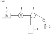
- FIG. 1 shows a configuration of a typical elevator system.
- a typical elevator system includes a hoist 1, a balance weight 2 and a car 3.
- An inverter 5 supplies a power to a motor 4.
- the hoist 1 is driven forward or backward by the motor 4 to move the car 3 up or down.
- a person or cargo is boarded on the car 3.
- the balance weight 2 is positioned opposite the car 3 with the hoist 1 interposed therebetween.
- the car 3 When the car 3 is moving between floors, the car 3 should be landed such that a top level of the car 3 exactly matches a top level of a target floor.
- a leveling error occurs and thus the car 3 has been landed such that a top level of the car 3 mismatches a top level of a target floor, a lot of inconvenience may occur when people get on and off the car 3. Even injuries may occur.
- a technique for reducing the leveling error is one of the most important techniques for the elevator system and is directly related to performance of the elevator system.
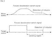
- FIG. 2 shows a change in a motor speed over time according to a target speed (command frequency) of an inverter when the elevator system in FIG. 1 sets a target floor and a car starts to move down or up.
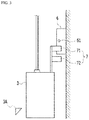
- FIG. 3 shows an example of a floor top level matching device in an elevator system.
- the motor 4 when a drive command is received from a higher level controller (not shown), the motor 4 is accelerated via an initial start. Then, a speed of the motor 4 reaches a first target speed and enters a constant-speed drive mode (constant-speed region). During the constant-speed drive mode of the motor, a speed-reducing command (deceleration switch signal) is executed via detection of a magnetic signal of an upper inductor 71. Thus, the motor 4 enters a leveling region after the deceleration. That is, the motor 4 enters a constant-speed drive at a second target speed (called a leveling speed) lower than the first target speed.
- a second target speed called a leveling speed
- a level sensor 61 located on a shielding plate 6 senses a magnetic signal of a lower inductor 72
- the inverter 5 receives a stop command and the motor 4 decelerates and stops.
- the deceleration and stop means that the car 4 reaches the target floor.
- a top-level matching error may depend on a travel distance of the car 3.
- the most important factor in the leveling region is a travel distance of the car 3 after receiving the stop command.
- a target speed of the inverter 5 is adjusted so that a level of the inductor 7 matches a top level of the target floor. This may be referred to as "level-matching operation".
- level-matching operation When the travel distance of the car 3 after the deceleration and stop command is constant regardless of an external condition, the leveling error hardly occurs.
- the motor 4 used in the elevator system is of an induction motor type, a slip may occur.
- a rotator of the induction motor rotates via a rotating magnetic field generated by a stator.
- the magnetic flux is not linked and thus an electromotive force is not generated, and thus a torque is not generated in the rotator.
- the rotator in order to generate torque, the rotator must rotate at a lower speed than a rotation speed of the rotating magnetic field from the stator.
- the slip may be used to indicate a degree by which the rotational speed of the rotator is lower than the rotation speed of the rotating magnetic field from the stator.
- a leveling error occurs.
- the leveling error occurs depending on the number of people on the car 3, a moving direction of the car 3, a load type, that is, a motoring load or a regenerative load, or an amount of the load.
- a motoring mode a torque is applied such that a direction of the load is opposite to the rotation direction of the motor 4.
- a regenerative mode a torque is applied such that a direction of the load is identical with the rotation direction of the motor 4.
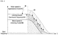
- FIG. 4 shows a relationship between the command frequency and an actual motor speed in the leveling region.
- a speed 4B of the motor 4 in the motoring mode and a speed 4C of the motor 4 in the regenerative mode differ from a leveling speed 4A as the command frequency by arrows 4D and 4E respectively.
- the sizes of the arrows 4D and 4E may depend on the amount of the load. That is, a difference between the command frequency and the actual motor speed may vary depending on the load amount. This phenomenon may be caused by the slip in the induction motor. The larger the load amount, the greater the slip size.
- the landing level may slightly vary.
- slip compensation was made.
- an amount of calculation until a correct compensation amount is obtained increases.
- it is difficult to distinguish between the regenerative mode and the monitoring mode it is difficult to accurately calculate the compensation amount.
- the most important section in the leveling region is a section after the stop command reception. This section is indicated by a shaded region in FIG. 4 . This section is important because the travel distance of the elevator car 3 until the elevator car 3 has landed after the level sensor 6 detects the inductor 7 is closely associated with a floor top-level matching error.
- FIG. 5 is a flow chart for illustrating a method for controlling the motor in accordance with one embodiment of the present disclosure.
- the inverter 5 controls the motor 4.
- the inverter 5 in accordance with an embodiment of the present disclosure receives a commercial power and converts the power into a power having a command frequency and a command voltage, and supplies the command frequency and command voltage to the motor 4 so as to control the motor 4.
- FIG. 6 is an example of an approach to reduce an leveling error in a motoring load.
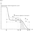
- FIG. 7 is an example of an approach to reduce an leveling error in an regenerative load. For each of the motoring load and regenerative load, a difference between the command frequency (target speed) and the actual motor speed may be checked.
- 6A represents the command frequency
- 6B represents the actual motor 4 speed
- a time-point 6D at which the magnetic signal of the lower inductor 72 (or the upper inductor 71) is sensed when driven at the command frequency may not coincide with a time-point 6E at which the magnetic signal of the lower inductor 72 (or the upper inductor 71) is sensed when driven at the actual motor 4 speed. This causes a non-coincidence between a stop time-point 6F when driven at the command frequency and a stop time-point 6G when driven at the actual motor 4 speed.
- FIG. 6 is an example of an approach to reduce an leveling error in a motoring load.
- FIG. 7 is an example of an approach to reduce an leveling error in an regenerative load. For each of the motoring load and regenerative load, a difference between the command frequency (target speed) and the actual motor speed may be checked.
- a time-point 7D at which the magnetic signal of the lower inductor 72 (or the upper inductor 71) is sensed when driven at the command frequency may not coincide with a time-point 7E at which the magnetic signal of the lower inductor 72 (or the upper inductor 71) is sensed when driven at the actual motor 4 speed. This causes a non-coincidence between a stop time-point 7F when driven at the command frequency and a stop time-point 7G when driven at the actual motor 4 speed.
- a section between a deceleration switch triggering time-point 6C and 7C and an inductor detection time-point 6E and 7E may be called T1; and a section between the inductor detection time-point 6E and 7E and the stop time-point 6G and 7G may be called T2.
- T1 a section between a deceleration switch triggering time-point 6C and 7C and an inductor detection time-point 6D and 7D
- T3 a section between the inductor detection time-point 6E and 7E and the stop time-point 6G and 7G may be called T2.
- the leveling operation is performed by applying different slip compensation amounts to the motoring load condition and the regenerative load condition respectively.
- the top level matching device of FIG. 3 will be described in more detail.
- the inductor 7 including the upper inductor 71 and the lower inductor 72 may be coupled to the car 3 and may be placed on a top of the car 3.
- the upper inductor 71 and the lower inductor 72 may be arranged to be spaced from each other vertically.
- each of the upper inductor 71 and lower inductor 72 may serve as a magnetic signal emitter for emitting a magnetic signal. More specifically, the upper inductor 71 may serve as a first magnetic signal emitter. The lower inductor 72 may also function as a second magnetic signal emitter. In contrast, the upper inductor 71 may serve as a second magnetic signal emitter. The lower inductor 72 may also function as a first magnetic signal emitter.
- the shielding plate 6 may be provided with the level sensor 61 for receiving an input of a magnetic sensor.
- the level sensor 61 may be disposed at a vertical middle position of the shielding plate 6.
- the present disclosure is not limited thereto.
- the level sensor 61 may be disposed at various positions on the shielding plate 6.
- the level sensor 61 may receive the magnetic signal from the upper inductor 71 and provide the signal to a controller (not shown) of the inverter 5.
- the controller of the inverter 5 Upon receiving the magnetic signal of the upper inductor 71, the controller of the inverter 5 reduces a current command frequency to a deceleration level. Then, the controller may provide the motor 4 with a new command frequency having the deceleration level.
- the level sensor 61 may receive the magnetic signal from the lower inductor 72 and provide the same to the controller of the inverter 5. Upon receiving the magnetic signal of the lower inductor 72, the controller may output a stop signal to the motor 4 or may not output any signal.
- the method may determine a time duration to adjust the travel distance of the car 3.
- FIG. 5 A method for controlling the motor in accordance with one embodiment of the present disclosure of FIG. 5 will be exemplified.
- the inverter 5 may trigger a deceleration switch to output an output voltage corresponding to a command frequency at a deceleration level to the motor 4.
- the inverter 5 then measures a time duration T1 from a deceleration switch trigger time point 6C and 7C to a time point 6E and 7E at which the level sensor 61 senses the magnetic signal from the lower inductor 72 (or upper inductor 71) S10.
- the inverter 5 may be equipped with means for time measurement.
- the inverter 5 calculates a time duration T3 from the deceleration switch trigger time-point 6C and 7C upon detection of the magnetic signal of the upper inductor 71 (or lower inductor 72) to a detection time point 6D and 7D of the magnetic signal of the lower inductor 72 (or upper inductor 71) S15.
- a distance between the upper inductor 71 (or lower inductor 72) and lower inductor 72 (or upper inductor 71) is applied equally to all of floors of a building with this elevator system. Accordingly, when the motor 4 is driven based on the output voltage corresponding to the actual command frequency, the distance between the upper inductor 71 (or lower inductor 72) and lower inductor 72 (or upper inductor 71) may be known, and, thus, the time duration T3 may be determined via calculation using the distance.
- the time duration T3 may be calculated based on the command frequency, not based on the actual motor speed. For example, the time duration required for the car 3 to travel by a distance of 1 meter based on the command frequency of 50 Hz may be T3. T1 is the actual measured value. Therefore, the speed of the motor 4 may be calculated by dividing the travel distance of the car 3 by the time duration T 1.
- the actual speed of the motor 4 in the corresponding region may be calculated S20.
- the time duration corresponding to the travel distance in a region T2 may be obtained.
- the travel distance of the car 3 for the time duration T2 from the time-point 6E and 7E at which the level sensor 61 senses the magnetic signal of the lower inductor 72 (or the upper inductor 71) to the time-point 6G at which the motor stops may be predetermined. That is, after the lower inductor 72 (or upper inductor 71) passes by the level sensor 61 and the car 3 stops, a position of the lower inductor 72 (or the upper inductor 71) is preset.
- the present method may know the travel distance and speed and thus may determine the time duration T2. In this connection, integrating the speed over the time duration as FIG. 6 and FIG. 7 results in the travel distance. In FIG. 6 and FIG. 7 , an area of the shaded section may amount to the travel distance.
- the time duration corresponds to the deceleration time duration of the inverter 5.
- the method may adjust the leveling error by adjusting the time duration S30. That is, the present method can allow the car 3 to accurately reach a top level of a target floor 3A by adjusting the time duration corresponding to the movement of the car 3 to T2.
- the method for controlling a motor determines the speed in the T1 region based on the measured time duration T1. Then, the method determines the deceleration time duration T2 after the time point 6E and 7E at which the level sensor 61 senses the magnetic signal of the lower inductor 72 (or upper inductor 71), thereby allowing the car 3 to stop accurately at the target stop position.
- the determination between the regenerative load situation and the motoring load situation and the calculation of the load amount are not separately required. Rather, measuring the time duration of each temporal section may allow the leveling error to be reduced. Thus, the ride comfort on the elevator car may be improved as compared with the conventional approach. This may improve the performance of the elevator system.
Landscapes
- Engineering & Computer Science (AREA)
- Automation & Control Theory (AREA)
- Computer Networks & Wireless Communication (AREA)
- Physics & Mathematics (AREA)
- General Physics & Mathematics (AREA)
- Elevator Control (AREA)
- Control Of Ac Motors In General (AREA)
- Stopping Of Electric Motors (AREA)
Abstract
Description
- The present disclosure relates to a method for controlling a motor in an elevator system.
- Generally, an inverter is an inverse conversion device that electrically converts DC to AC. An inverter used in the industry is defined as a series of devices that control a motor speed such that the motor is used with a high efficiency by receiving a power supplied from a commercial power supply and varying a voltage and frequency of the power by itself and supplying the varied power to the motor. The inverter is controlled via a variable voltage variable frequency (WVF) scheme. The inverter may vary a voltage and frequency input to the motor based on a pulse width modulation (PWM) output.
- Usually, the inverter being driven by a V/f control mode may mean that the inverter may control a frequency according to a magnitude of a voltage. In this connection, a speed sensor (encoder) for measuring a rotational speed of the motor is not used for the V/f control. Therefore, when the elevator system is operated in the V/f control mode, an accurate travel distance of an elevator car cannot be calculated.
- Nevertheless, a price of the speed sensor such as the encoder is high, and, thus, in a low-cost elevator system, the elevator car is operated with estimating the rotation speed of the motor without the speed sensor. Accordingly, the conventional elevator system has a problem that the stability of the system is low due to the limitation that the travel distance of the elevator car cannot be accurately calculated.
- In order to solve the problem, a purpose of the present disclosure is to provide a method for controlling a motor in an elevator system adopting the voltage/frequency (V/f) control scheme which does not use the speed sensor, in which an accuracy of a vertical level position error of the elevator car in the elevator car landing is improved to increase performance of the elevator system.
- In one aspect of the present disclosure, there is provided a method for controlling a motor in an elevator system, wherein in the elevator system, a level sensor is disposed at a fixed position on each floor of a building, and a first magnetic signal emitter and a second magnetic signal emitter are coupled to a car and are vertically arranged to be spaced from each other above the car, and the motor operates to move the car upward or downward, wherein the method comprises: when the level sensor receives a magnetic signal from the first magnetic signal emitter, outputting, to the motor, an output voltage corresponding to a command frequency at a deceleration level; measuring a first time duration from a first time-point at which the level sensor receives the magnetic signal of the first magnetic signal emitter to a second time-point at which the level sensor receives a magnetic signal from the second magnetic signal emitter; calculating an actual speed of the motor using the first time duration; determining a second time duration from the second time-point to a third time-point at which the car stops, using the actual speed and a predetermined travel distance; and adjusting an leveling error using the second time duration.
- In one implementation, the actual speed of the motor is calculated by dividing a distance between the first and second magnetic signal emitters by the first time duration.
- In one implementation, adjusting the leveling error includes moving the
car 3 during the second time duration to allow arrive at a target floor level. - In one implementation, each of the first and second magnetic signal emitters includes an inductor.
- In the method for controlling the motor according to an embodiment of the present disclosure, the determination between the regenerative load situation and the motoring load situation and the calculation of the load amount are not separately required. Rather, measuring the time duration of each temporal section may allow the leveling error to be reduced. Thus, the ride comfort on the elevator car may be improved as compared with the conventional approach. This may improve the performance of the elevator system.
- Further specific effects of the present disclosure as well as the effects as described above will be described in conduction with illustrations of specific details for carrying out the invention.
-
-
FIG. 1 shows a configuration of a typical elevator system. -
FIG. 2 shows a change in a motor speed over time according to a target speed (command frequency) of an inverter when the elevator system inFIG. 1 sets a target floor and a car starts to move down or up. -
FIG. 3 shows an example of a floor top level matching device in an elevator system. -
FIG. 4 shows a relationship between a command frequency and an actual motor speed in a leveling region. -
FIG. 5 is a flow chart for illustrating a method for controlling a motor in accordance with one embodiment of the present disclosure. -
FIG. 6 is an example of an approach to reduce an leveling error in a motoring load. -
FIG. 7 is an example of an approach to reduce an leveling error in an regenerative load. - Hereinafter, a method for controlling a motor in an elevator system in accordance with the present disclosure will be described with reference to the accompanying drawings.
- For simplicity and clarity of illustration, elements in the figures, are not necessarily drawn to scale. The same reference numbers in different figures, denote the same or similar elements, and as such perform similar functionality. Further, descriptions and details of well-known steps and elements are omitted for simplicity of the description. Furthermore, in the following detailed description of the present disclosure, numerous specific details are set forth in order to provide a thorough understanding of the present disclosure. However, it will be understood that the present disclosure may be practiced without these specific details. In other instances, well-known methods, procedures, components, and circuits have not been described in detail so as not to unnecessarily obscure aspects of the present disclosure.
- The above objects, features and advantages will become apparent from the detailed description with reference to the accompanying drawings. Embodiments are described in sufficient detail to enable those skilled in the art in the art to easily practice the technical idea of the present disclosure. Detailed descriptions of well-known functions or configurations may be omitted in order not to unnecessarily obscure the gist of the present disclosure. Hereinafter, embodiments of the present disclosure will be described in detail with reference to the accompanying drawings. Throughout the drawings, like reference numerals refer to like elements.
- Unless defined otherwise, all terms used herein have the same meaning as commonly understood by one of ordinary skill in the art. When the terms used herein are in conflict with a general meaning of the term, the meaning of the term is in accordance with a definition used herein.
- Examples of various embodiments are illustrated and described further below. It will be understood that the description herein is not intended to limit the claims to the specific embodiments described. On the contrary, it is intended to cover alternatives, modifications, and equivalents as may be included within the spirit and scope of the present disclosure as defined by the appended claims.
- The terminology used herein is for the purpose of describing particular embodiments only and is not intended to be limiting of the present disclosure. As used herein, the singular forms "a" and "an" are intended to include the plural forms as well, unless the context clearly indicates otherwise. It will be further understood that the terms "comprises", "comprising", "includes", and "including" when used in this specification, specify the presence of the stated features, integers, operations, elements, and/or components, but do not preclude the presence or addition of one or more other features, integers, operations, elements, components, and/or portions thereof. As used herein, the term "and/or" includes any and all combinations of one or more of the associated listed items. Expression such as "at least one of' when preceding a list of elements may modify the entire list of elements and may not modify the individual elements of the list.
- It will be understood that, although the terms "first", "second", "third", and so on may be used herein to describe various elements, components, regions, layers and/or sections, these elements, components, regions, layers and/or sections should not be limited by these terms. These terms are used to distinguish one element, component, region, layer or section from another element, component, region, layer or section. Thus, a first element, component, region, layer or section described below could be termed a second element, component, region, layer or section, without departing from the spirit and scope of the present disclosure.
- In addition, it will also be understood that when a first element or layer is referred to as being present "on" a second element or layer, the first element may be disposed directly on the second element or may be disposed indirectly on the second element with a third element or layer being disposed between the first and second elements or layers. It will be understood that when an element or layer is referred to as being "connected to", or "coupled to" another element or layer, it can be directly on, connected to, or coupled to the other element or layer, or one or more intervening elements or layers may be present. In addition, it will also be understood that when an element or layer is referred to as being "between" two elements or layers, it can be the only element or layer between the two elements or layers, or one or more intervening elements or layers may also be present.
- Hereinafter, a leveling operation in a conventional elevator system will be described with reference to
FIGS. 1 to 4 . A method for controlling a motor in the elevator system according to an embodiment of the present disclosure will be described with reference toFIGS. 5 to 7 . -
FIG. 1 shows a configuration of a typical elevator system. - As shown in
FIG. 1 , a typical elevator system includes a hoist 1, a balance weight 2 and acar 3. Aninverter 5 supplies a power to a motor 4. The hoist 1 is driven forward or backward by the motor 4 to move thecar 3 up or down. A person or cargo is boarded on thecar 3. The balance weight 2 is positioned opposite thecar 3 with the hoist 1 interposed therebetween. - When the
car 3 is moving between floors, thecar 3 should be landed such that a top level of thecar 3 exactly matches a top level of a target floor. When a leveling error occurs and thus thecar 3 has been landed such that a top level of thecar 3 mismatches a top level of a target floor, a lot of inconvenience may occur when people get on and off thecar 3. Even injuries may occur. - Thus, a technique for reducing the leveling error is one of the most important techniques for the elevator system and is directly related to performance of the elevator system.
-
FIG. 2 shows a change in a motor speed over time according to a target speed (command frequency) of an inverter when the elevator system inFIG. 1 sets a target floor and a car starts to move down or up.FIG. 3 shows an example of a floor top level matching device in an elevator system. - As shown in
FIG. 2 , when a drive command is received from a higher level controller (not shown), the motor 4 is accelerated via an initial start. Then, a speed of the motor 4 reaches a first target speed and enters a constant-speed drive mode (constant-speed region). During the constant-speed drive mode of the motor, a speed-reducing command (deceleration switch signal) is executed via detection of a magnetic signal of anupper inductor 71. Thus, the motor 4 enters a leveling region after the deceleration. That is, the motor 4 enters a constant-speed drive at a second target speed (called a leveling speed) lower than the first target speed. - Referring to
FIG. 3 , when, after the second constant-speed drive in the leveling region, alevel sensor 61 located on ashielding plate 6 senses a magnetic signal of alower inductor 72, theinverter 5 receives a stop command and the motor 4 decelerates and stops. The deceleration and stop means that the car 4 reaches the target floor. In this connection, a top-level matching error may depend on a travel distance of thecar 3. The most important factor in the leveling region is a travel distance of thecar 3 after receiving the stop command. - In an elevator system employing the V/f control mode in which a calculation of the travel distance of the
car 3 is difficult, a target speed of theinverter 5 is adjusted so that a level of theinductor 7 matches a top level of the target floor. This may be referred to as "level-matching operation". When the travel distance of thecar 3 after the deceleration and stop command is constant regardless of an external condition, the leveling error hardly occurs. However, when the motor 4 used in the elevator system is of an induction motor type, a slip may occur. - A rotator of the induction motor rotates via a rotating magnetic field generated by a stator. In this connection, when the rotator rotates at the same speed as a rotation speed of the rotating magnetic field, the magnetic flux is not linked and thus an electromotive force is not generated, and thus a torque is not generated in the rotator. In other words, in order to generate torque, the rotator must rotate at a lower speed than a rotation speed of the rotating magnetic field from the stator. The slip may be used to indicate a degree by which the rotational speed of the rotator is lower than the rotation speed of the rotating magnetic field from the stator.
- Since the slip may vary depending on a load, a leveling error occurs. Eventually, the leveling error occurs depending on the number of people on the
car 3, a moving direction of thecar 3, a load type, that is, a motoring load or a regenerative load, or an amount of the load. In a motoring mode, a torque is applied such that a direction of the load is opposite to the rotation direction of the motor 4. In a regenerative mode, a torque is applied such that a direction of the load is identical with the rotation direction of the motor 4. - A reason for the leveling error occurrence may be identified with reference to
FIG. 4. FIG. 4 shows a relationship between the command frequency and an actual motor speed in the leveling region. - A
speed 4B of the motor 4 in the motoring mode and aspeed 4C of the motor 4 in the regenerative mode differ from aleveling speed 4A as the command frequency byarrows arrows - Due to this difference, the landing level may slightly vary. To overcome this problem, slip compensation was made. However, when a slip compensation algorithm is used, an amount of calculation until a correct compensation amount is obtained increases. Further, since it is difficult to distinguish between the regenerative mode and the monitoring mode, it is difficult to accurately calculate the compensation amount.
- Even when the correct compensation amount is calculated, a shock may occur in the landing phase, which adversely affects the ride comfort of the person on the
car 3. This is because a voltage corresponding to the slip compensation amount is additionally applied to the motor 4, and, thus, the shock may occur due to an additional compensation amount corresponding to the slip compensation amount at the landing phase. As a result, the performance of the elevator system is not greatly improved. - The most important section in the leveling region is a section after the stop command reception. This section is indicated by a shaded region in
FIG. 4 . This section is important because the travel distance of theelevator car 3 until theelevator car 3 has landed after thelevel sensor 6 detects theinductor 7 is closely associated with a floor top-level matching error. Hereinafter, a method for controlling a motor in accordance with an embodiment of the present disclosure will be described with reference to the drawings. -
FIG. 5 is a flow chart for illustrating a method for controlling the motor in accordance with one embodiment of the present disclosure. In this control method, in the elevator system ofFIG. 1 , theinverter 5 controls the motor 4. Theinverter 5 in accordance with an embodiment of the present disclosure receives a commercial power and converts the power into a power having a command frequency and a command voltage, and supplies the command frequency and command voltage to the motor 4 so as to control the motor 4. -
FIG. 6 is an example of an approach to reduce an leveling error in a motoring load.FIG. 7 is an example of an approach to reduce an leveling error in an regenerative load. For each of the motoring load and regenerative load, a difference between the command frequency (target speed) and the actual motor speed may be checked. - In
FIG. 6 , in the motoring load situation, in a section of the leveling region after a deceleration switch signal is triggered via detection of the magnetic signal of the upper inductor 71 (or the lower inductor 72), and in which the magnetic signal of the lower inductor 72 (or upper inductor 71) is sensed, 6A represents the command frequency, and 6B represents the actual motor 4 speed. - A time-
point 6D at which the magnetic signal of the lower inductor 72 (or the upper inductor 71) is sensed when driven at the command frequency may not coincide with a time-point 6E at which the magnetic signal of the lower inductor 72 (or the upper inductor 71) is sensed when driven at the actual motor 4 speed. This causes a non-coincidence between a stop time-point 6F when driven at the command frequency and a stop time-point 6G when driven at the actual motor 4 speed. -
FIG. 6 is an example of an approach to reduce an leveling error in a motoring load.FIG. 7 is an example of an approach to reduce an leveling error in an regenerative load. For each of the motoring load and regenerative load, a difference between the command frequency (target speed) and the actual motor speed may be checked. - In
FIG. 7 , in the regenerative load situation, in a section of the leveling region after a deceleration switch signal is triggered via detection of the magnetic signal of the upper inductor 71 (or the lower inductor 72), and in which the magnetic signal of the lower inductor 72 (or upper inductor 71) is sensed, 7A represents the command frequency, and 7B represents the actual motor 4 speed. - A time-
point 7D at which the magnetic signal of the lower inductor 72 (or the upper inductor 71) is sensed when driven at the command frequency may not coincide with a time-point 7E at which the magnetic signal of the lower inductor 72 (or the upper inductor 71) is sensed when driven at the actual motor 4 speed. This causes a non-coincidence between a stop time-point 7F when driven at the command frequency and a stop time-point 7G when driven at the actual motor 4 speed. - In each of the motoring and regenerative load situations, following definitions may be set forth. When driven at the actual motor 4 speed, a section between a deceleration switch triggering time-
point point point point point point point point - According to the conventional slip compensation algorithm, to distinguish between the motoring load condition and the regenerative load condition is required. Then, the leveling operation is performed by applying different slip compensation amounts to the motoring load condition and the regenerative load condition respectively. However, According to one embodiment of the present disclosure, there is no separate need to distinguish between the motoring load situation and the regenerative load situation.
- The top level matching device of
FIG. 3 will be described in more detail. - The
inductor 7 including theupper inductor 71 and thelower inductor 72 may be coupled to thecar 3 and may be placed on a top of thecar 3. In this connection, theupper inductor 71 and thelower inductor 72 may be arranged to be spaced from each other vertically. - In one example, each of the
upper inductor 71 andlower inductor 72 may serve as a magnetic signal emitter for emitting a magnetic signal. More specifically, theupper inductor 71 may serve as a first magnetic signal emitter. Thelower inductor 72 may also function as a second magnetic signal emitter. In contrast, theupper inductor 71 may serve as a second magnetic signal emitter. Thelower inductor 72 may also function as a first magnetic signal emitter. - The shielding
plate 6 may be provided with thelevel sensor 61 for receiving an input of a magnetic sensor. For example, thelevel sensor 61 may be disposed at a vertical middle position of theshielding plate 6. However, the present disclosure is not limited thereto. Thelevel sensor 61 may be disposed at various positions on theshielding plate 6. - When the
upper inductor 71 reaches a position corresponding to thelevel sensor 61 of theshielding plate 6, thelevel sensor 61 may receive the magnetic signal from theupper inductor 71 and provide the signal to a controller (not shown) of theinverter 5. Upon receiving the magnetic signal of theupper inductor 71, the controller of theinverter 5 reduces a current command frequency to a deceleration level. Then, the controller may provide the motor 4 with a new command frequency having the deceleration level. - Then, when the
lower inductor 72 reaches a position corresponding to thelevel sensor 61 of theshielding plate 6, thelevel sensor 61 may receive the magnetic signal from thelower inductor 72 and provide the same to the controller of theinverter 5. Upon receiving the magnetic signal of thelower inductor 72, the controller may output a stop signal to the motor 4 or may not output any signal. - However, this is an example of a case where the
car 3 moves in the upward direction. It will be appreciated that when thecar 3 moves downwards, a detection order of the upper andlower inductors - In a method for controlling a motor in accordance with an embodiment of the present disclosure, when the
car 3 moves based on the command frequency, the actual travel distance of thecar 3 is already determined. Thus, an operating time of the motor 4 may be known when the motor 4 is driven based on the command frequency. Therefore, when thecar 3 moves based on the actual speed of the motor 4 higher or lower than the actual command frequency, the method may determine a time duration to adjust the travel distance of thecar 3. - A method for controlling the motor in accordance with one embodiment of the present disclosure of
FIG. 5 will be exemplified. - As shown in
FIG. 5 , in the method for controlling the motor according to the present disclosure, when the motor 4 is driven based on an output voltage corresponding to a command frequency at a normal level and thus thecar 3 moves up or down, and then when thelevel sensor 61 receives a magnetic signal from the upper inductor 71 (or the lower inductor 72), theinverter 5 may trigger a deceleration switch to output an output voltage corresponding to a command frequency at a deceleration level to the motor 4. - The
inverter 5 then measures a time duration T1 from a deceleration switchtrigger time point time point level sensor 61 senses the magnetic signal from the lower inductor 72 (or upper inductor 71) S10. For this purpose, theinverter 5 may be equipped with means for time measurement. - Thereafter, when the motor 4 is driven based on an output voltage corresponding to the command frequency, the
inverter 5 calculates a time duration T3 from the deceleration switch trigger time-point detection time point - A distance between the upper inductor 71 (or lower inductor 72) and lower inductor 72 (or upper inductor 71) is applied equally to all of floors of a building with this elevator system. Accordingly, when the motor 4 is driven based on the output voltage corresponding to the actual command frequency, the distance between the upper inductor 71 (or lower inductor 72) and lower inductor 72 (or upper inductor 71) may be known, and, thus, the time duration T3 may be determined via calculation using the distance.
- The time duration T3 may be calculated based on the command frequency, not based on the actual motor speed. For example, the time duration required for the
car 3 to travel by a distance of 1 meter based on the command frequency of 50 Hz may be T3. T1 is the actual measured value. Therefore, the speed of the motor 4 may be calculated by dividing the travel distance of thecar 3 by the time duration T 1. - Using the measured time duration T1, the actual speed of the motor 4 in the corresponding region may be calculated S20.
- Using the motor speed thus calculated, the time duration corresponding to the travel distance in a region T2 may be obtained.
- That is, the travel distance of the
car 3 for the time duration T2 from the time-point level sensor 61 senses the magnetic signal of the lower inductor 72 (or the upper inductor 71) to the time-point 6G at which the motor stops may be predetermined. That is, after the lower inductor 72 (or upper inductor 71) passes by thelevel sensor 61 and thecar 3 stops, a position of the lower inductor 72 (or the upper inductor 71) is preset. Thus, the present method may know the travel distance and speed and thus may determine the time duration T2. In this connection, integrating the speed over the time duration asFIG. 6 andFIG. 7 results in the travel distance. InFIG. 6 andFIG. 7 , an area of the shaded section may amount to the travel distance. - The time duration corresponds to the deceleration time duration of the
inverter 5. Thus, the method may adjust the leveling error by adjusting the time duration S30. That is, the present method can allow thecar 3 to accurately reach a top level of atarget floor 3A by adjusting the time duration corresponding to the movement of thecar 3 to T2. - The method for controlling a motor according to an embodiment of the present disclosure determines the speed in the T1 region based on the measured time duration T1. Then, the method determines the deceleration time duration T2 after the
time point level sensor 61 senses the magnetic signal of the lower inductor 72 (or upper inductor 71), thereby allowing thecar 3 to stop accurately at the target stop position. - In the method for controlling the motor according to an embodiment of the present disclosure, the determination between the regenerative load situation and the motoring load situation and the calculation of the load amount are not separately required. Rather, measuring the time duration of each temporal section may allow the leveling error to be reduced. Thus, the ride comfort on the elevator car may be improved as compared with the conventional approach. This may improve the performance of the elevator system.
- It will be apparent to those skilled in the art that various modifications and variations may be made in the present invention without departing from the spirit of the present disclosure. The technical scope of the present disclosure is not limited to the contents described in the embodiments but should be determined by the claims and equivalents thereof.
Claims (4)
- A method for controlling a motor 4 in an elevator system,
wherein in the elevator system, a level sensor 61 is disposed at a fixed position on each floor of a building, and a first magnetic signal emitter 71 and a second magnetic signal emitter 72 are coupled to a car 3 and are vertically arranged to be spaced from each other above the car 3, and the motor 4 operates to move the car 3 upward or downward,
wherein the method comprises:outputting, to the motor 4, an output voltage corresponding to a command frequency at a deceleration level when the level sensor 61 receives a magnetic signal from the first magnetic signal emitter 71;measuring a first time duration from a first time-point at which the level sensor 61 receives the magnetic signal of the first magnetic signal emitter 71 to a second time-point at which the level sensor 61 receives a magnetic signal from the second magnetic signal emitter 72;calculating an actual speed of the motor 4 using the first time duration;determining a second time duration from the second time-point to a third time-point at which the car 3 stops, using the actual speed and a predetermined travel distance; andadjusting an leveling error using the second time duration. - The method of claim 1, wherein the actual speed of the motor 4 is calculated by dividing a distance between the first and second magnetic signal emitters by the first time duration.
- The method of claim 1, wherein adjusting the leveling error includes moving the car 3 during the second time duration to allow arrive at a target floor level.
- The method of claim 1, wherein each of the first and second magnetic signal emitters includes an inductor.
Applications Claiming Priority (1)
| Application Number | Priority Date | Filing Date | Title |
|---|---|---|---|
| KR1020180054633A KR102081157B1 (en) | 2018-05-14 | 2018-05-14 | Method for controlling motor in elevator system |
Publications (2)
| Publication Number | Publication Date |
|---|---|
| EP3569543A1 true EP3569543A1 (en) | 2019-11-20 |
| EP3569543B1 EP3569543B1 (en) | 2022-04-20 |
Family
ID=65812108
Family Applications (1)
| Application Number | Title | Priority Date | Filing Date |
|---|---|---|---|
| EP19162676.1A Active EP3569543B1 (en) | 2018-05-14 | 2019-03-13 | Method for controlling motor in elevator system |
Country Status (6)
| Country | Link |
|---|---|
| US (1) | US20190344996A1 (en) |
| EP (1) | EP3569543B1 (en) |
| JP (1) | JP6728424B2 (en) |
| KR (1) | KR102081157B1 (en) |
| CN (1) | CN110482343B (en) |
| ES (1) | ES2916578T3 (en) |
Families Citing this family (2)
| Publication number | Priority date | Publication date | Assignee | Title |
|---|---|---|---|---|
| CN115636308A (en) * | 2021-07-19 | 2023-01-24 | 崇友实业股份有限公司 | Pneumatic elevator system and control method thereof |
| KR102913183B1 (en) | 2025-05-16 | 2026-01-16 | (주)신우프론티어 | Elevator signal light system |
Citations (3)
| Publication number | Priority date | Publication date | Assignee | Title |
|---|---|---|---|---|
| EP0792833A2 (en) * | 1996-02-29 | 1997-09-03 | Otis Elevator Company | Elevator leveling adjustment |
| WO2010134158A1 (en) * | 2009-05-19 | 2010-11-25 | 三菱電機株式会社 | Elevator abnormality detection device |
| KR20140056081A (en) * | 2012-10-31 | 2014-05-09 | 미쓰비시덴키 가부시키가이샤 | Magnetic switch device and position sensing apparatus of elevator car using the same |
Family Cites Families (6)
| Publication number | Priority date | Publication date | Assignee | Title |
|---|---|---|---|---|
| JPS60128884A (en) * | 1983-11-28 | 1985-07-09 | Mitsubishi Electric Corp | Speed controller of elevator |
| JPH03259875A (en) * | 1990-03-08 | 1991-11-19 | Toshiba Corp | Speed reference auto tuning device for elevator |
| KR19990056789A (en) * | 1997-12-29 | 1999-07-15 | 이해규 | Stop position prediction method of moving object |
| JP4618636B2 (en) * | 2004-12-07 | 2011-01-26 | 三菱電機株式会社 | Elevator equipment |
| US9067762B2 (en) * | 2009-07-15 | 2015-06-30 | Otis Elevator Company | Energy savings with optimized motion profiles |
| CN105173935B (en) * | 2015-08-06 | 2017-04-05 | 日立电梯(中国)有限公司 | The control device and method of level position of elevator |
-
2018
- 2018-05-14 KR KR1020180054633A patent/KR102081157B1/en active Active
-
2019
- 2019-02-27 JP JP2019034226A patent/JP6728424B2/en not_active Expired - Fee Related
- 2019-03-12 US US16/299,946 patent/US20190344996A1/en not_active Abandoned
- 2019-03-13 ES ES19162676T patent/ES2916578T3/en active Active
- 2019-03-13 EP EP19162676.1A patent/EP3569543B1/en active Active
- 2019-03-22 CN CN201910222034.8A patent/CN110482343B/en active Active
Patent Citations (3)
| Publication number | Priority date | Publication date | Assignee | Title |
|---|---|---|---|---|
| EP0792833A2 (en) * | 1996-02-29 | 1997-09-03 | Otis Elevator Company | Elevator leveling adjustment |
| WO2010134158A1 (en) * | 2009-05-19 | 2010-11-25 | 三菱電機株式会社 | Elevator abnormality detection device |
| KR20140056081A (en) * | 2012-10-31 | 2014-05-09 | 미쓰비시덴키 가부시키가이샤 | Magnetic switch device and position sensing apparatus of elevator car using the same |
Also Published As
| Publication number | Publication date |
|---|---|
| JP6728424B2 (en) | 2020-07-22 |
| CN110482343B (en) | 2021-07-06 |
| KR102081157B1 (en) | 2020-02-25 |
| ES2916578T3 (en) | 2022-07-01 |
| JP2019199362A (en) | 2019-11-21 |
| US20190344996A1 (en) | 2019-11-14 |
| EP3569543B1 (en) | 2022-04-20 |
| CN110482343A (en) | 2019-11-22 |
| KR20190130232A (en) | 2019-11-22 |
Similar Documents
| Publication | Publication Date | Title |
|---|---|---|
| CN107207209B (en) | Cordless Elevator Control System | |
| US8348020B2 (en) | Elevator control device with carrier frequency switch circuit | |
| EP2454182B1 (en) | Energy savings with optimized motion profiles | |
| JP2009005440A (en) | Induction motor drive device, motor drive system, and lifting system | |
| JP3936578B2 (en) | Elevator hoisting machine and control system | |
| CN101360675B (en) | Control apparatus for elevator | |
| CN101674996B (en) | Elevator | |
| EP3569543B1 (en) | Method for controlling motor in elevator system | |
| CN104854009B (en) | elevator speed control | |
| KR960003012B1 (en) | Adjusting device of elevator | |
| US5869795A (en) | Elevator floor arrival correction control | |
| CN105246812B (en) | For controlling the device of no current brake | |
| JP5036147B2 (en) | Elevator speed control device, speed control method, and speed control program | |
| KR20160043301A (en) | Over heat detector of motor | |
| JP2005041672A (en) | Elevator control device and control method | |
| CN117208692A (en) | Position detection system and method using magnetic sensors | |
| JP2011173704A (en) | Methods and system for measuring secondary time constant of induction electric motor for driving elevator | |
| JP2002046949A (en) | Home elevator landing controller | |
| JPH04313582A (en) | Elevator adjusting device | |
| JP2006193297A (en) | Elevator equipment | |
| JP2006131405A (en) | Elevator landing control device | |
| JP7031077B2 (en) | Elevator control device and elevator control method | |
| KR20030080149A (en) | Floor height measurement method for elevator | |
| JPH0631138B2 (en) | AC elevator automatic landing control device for blackouts | |
| JP2002220165A (en) | Induction motor control device |
Legal Events
| Date | Code | Title | Description |
|---|---|---|---|
| PUAI | Public reference made under article 153(3) epc to a published international application that has entered the european phase |
Free format text: ORIGINAL CODE: 0009012 |
|
| STAA | Information on the status of an ep patent application or granted ep patent |
Free format text: STATUS: THE APPLICATION HAS BEEN PUBLISHED |
|
| AK | Designated contracting states |
Kind code of ref document: A1 Designated state(s): AL AT BE BG CH CY CZ DE DK EE ES FI FR GB GR HR HU IE IS IT LI LT LU LV MC MK MT NL NO PL PT RO RS SE SI SK SM TR |
|
| AX | Request for extension of the european patent |
Extension state: BA ME |
|
| STAA | Information on the status of an ep patent application or granted ep patent |
Free format text: STATUS: REQUEST FOR EXAMINATION WAS MADE |
|
| 17P | Request for examination filed |
Effective date: 20200512 |
|
| RBV | Designated contracting states (corrected) |
Designated state(s): AL AT BE BG CH CY CZ DE DK EE ES FI FR GB GR HR HU IE IS IT LI LT LU LV MC MK MT NL NO PL PT RO RS SE SI SK SM TR |
|
| GRAP | Despatch of communication of intention to grant a patent |
Free format text: ORIGINAL CODE: EPIDOSNIGR1 |
|
| STAA | Information on the status of an ep patent application or granted ep patent |
Free format text: STATUS: GRANT OF PATENT IS INTENDED |
|
| INTG | Intention to grant announced |
Effective date: 20211222 |
|
| GRAS | Grant fee paid |
Free format text: ORIGINAL CODE: EPIDOSNIGR3 |
|
| GRAA | (expected) grant |
Free format text: ORIGINAL CODE: 0009210 |
|
| STAA | Information on the status of an ep patent application or granted ep patent |
Free format text: STATUS: THE PATENT HAS BEEN GRANTED |
|
| AK | Designated contracting states |
Kind code of ref document: B1 Designated state(s): AL AT BE BG CH CY CZ DE DK EE ES FI FR GB GR HR HU IE IS IT LI LT LU LV MC MK MT NL NO PL PT RO RS SE SI SK SM TR |
|
| REG | Reference to a national code |
Ref country code: GB Ref legal event code: FG4D |
|
| REG | Reference to a national code |
Ref country code: CH Ref legal event code: EP |
|
| REG | Reference to a national code |
Ref country code: IE Ref legal event code: FG4D |
|
| REG | Reference to a national code |
Ref country code: DE Ref legal event code: R096 Ref document number: 602019013803 Country of ref document: DE |
|
| REG | Reference to a national code |
Ref country code: AT Ref legal event code: REF Ref document number: 1485029 Country of ref document: AT Kind code of ref document: T Effective date: 20220515 |
|
| REG | Reference to a national code |
Ref country code: ES Ref legal event code: FG2A Ref document number: 2916578 Country of ref document: ES Kind code of ref document: T3 Effective date: 20220701 |
|
| REG | Reference to a national code |
Ref country code: LT Ref legal event code: MG9D |
|
| REG | Reference to a national code |
Ref country code: NL Ref legal event code: MP Effective date: 20220420 |
|
| REG | Reference to a national code |
Ref country code: AT Ref legal event code: MK05 Ref document number: 1485029 Country of ref document: AT Kind code of ref document: T Effective date: 20220420 |
|
| PG25 | Lapsed in a contracting state [announced via postgrant information from national office to epo] |
Ref country code: NL Free format text: LAPSE BECAUSE OF FAILURE TO SUBMIT A TRANSLATION OF THE DESCRIPTION OR TO PAY THE FEE WITHIN THE PRESCRIBED TIME-LIMIT Effective date: 20220420 |
|
| PG25 | Lapsed in a contracting state [announced via postgrant information from national office to epo] |
Ref country code: SE Free format text: LAPSE BECAUSE OF FAILURE TO SUBMIT A TRANSLATION OF THE DESCRIPTION OR TO PAY THE FEE WITHIN THE PRESCRIBED TIME-LIMIT Effective date: 20220420 Ref country code: PT Free format text: LAPSE BECAUSE OF FAILURE TO SUBMIT A TRANSLATION OF THE DESCRIPTION OR TO PAY THE FEE WITHIN THE PRESCRIBED TIME-LIMIT Effective date: 20220822 Ref country code: NO Free format text: LAPSE BECAUSE OF FAILURE TO SUBMIT A TRANSLATION OF THE DESCRIPTION OR TO PAY THE FEE WITHIN THE PRESCRIBED TIME-LIMIT Effective date: 20220720 Ref country code: LT Free format text: LAPSE BECAUSE OF FAILURE TO SUBMIT A TRANSLATION OF THE DESCRIPTION OR TO PAY THE FEE WITHIN THE PRESCRIBED TIME-LIMIT Effective date: 20220420 Ref country code: HR Free format text: LAPSE BECAUSE OF FAILURE TO SUBMIT A TRANSLATION OF THE DESCRIPTION OR TO PAY THE FEE WITHIN THE PRESCRIBED TIME-LIMIT Effective date: 20220420 Ref country code: GR Free format text: LAPSE BECAUSE OF FAILURE TO SUBMIT A TRANSLATION OF THE DESCRIPTION OR TO PAY THE FEE WITHIN THE PRESCRIBED TIME-LIMIT Effective date: 20220721 Ref country code: FI Free format text: LAPSE BECAUSE OF FAILURE TO SUBMIT A TRANSLATION OF THE DESCRIPTION OR TO PAY THE FEE WITHIN THE PRESCRIBED TIME-LIMIT Effective date: 20220420 Ref country code: BG Free format text: LAPSE BECAUSE OF FAILURE TO SUBMIT A TRANSLATION OF THE DESCRIPTION OR TO PAY THE FEE WITHIN THE PRESCRIBED TIME-LIMIT Effective date: 20220720 Ref country code: AT Free format text: LAPSE BECAUSE OF FAILURE TO SUBMIT A TRANSLATION OF THE DESCRIPTION OR TO PAY THE FEE WITHIN THE PRESCRIBED TIME-LIMIT Effective date: 20220420 |
|
| PG25 | Lapsed in a contracting state [announced via postgrant information from national office to epo] |
Ref country code: RS Free format text: LAPSE BECAUSE OF FAILURE TO SUBMIT A TRANSLATION OF THE DESCRIPTION OR TO PAY THE FEE WITHIN THE PRESCRIBED TIME-LIMIT Effective date: 20220420 Ref country code: PL Free format text: LAPSE BECAUSE OF FAILURE TO SUBMIT A TRANSLATION OF THE DESCRIPTION OR TO PAY THE FEE WITHIN THE PRESCRIBED TIME-LIMIT Effective date: 20220420 Ref country code: LV Free format text: LAPSE BECAUSE OF FAILURE TO SUBMIT A TRANSLATION OF THE DESCRIPTION OR TO PAY THE FEE WITHIN THE PRESCRIBED TIME-LIMIT Effective date: 20220420 Ref country code: IS Free format text: LAPSE BECAUSE OF FAILURE TO SUBMIT A TRANSLATION OF THE DESCRIPTION OR TO PAY THE FEE WITHIN THE PRESCRIBED TIME-LIMIT Effective date: 20220820 |
|
| REG | Reference to a national code |
Ref country code: DE Ref legal event code: R097 Ref document number: 602019013803 Country of ref document: DE |
|
| PG25 | Lapsed in a contracting state [announced via postgrant information from national office to epo] |
Ref country code: SM Free format text: LAPSE BECAUSE OF FAILURE TO SUBMIT A TRANSLATION OF THE DESCRIPTION OR TO PAY THE FEE WITHIN THE PRESCRIBED TIME-LIMIT Effective date: 20220420 Ref country code: SK Free format text: LAPSE BECAUSE OF FAILURE TO SUBMIT A TRANSLATION OF THE DESCRIPTION OR TO PAY THE FEE WITHIN THE PRESCRIBED TIME-LIMIT Effective date: 20220420 Ref country code: RO Free format text: LAPSE BECAUSE OF FAILURE TO SUBMIT A TRANSLATION OF THE DESCRIPTION OR TO PAY THE FEE WITHIN THE PRESCRIBED TIME-LIMIT Effective date: 20220420 Ref country code: EE Free format text: LAPSE BECAUSE OF FAILURE TO SUBMIT A TRANSLATION OF THE DESCRIPTION OR TO PAY THE FEE WITHIN THE PRESCRIBED TIME-LIMIT Effective date: 20220420 Ref country code: DK Free format text: LAPSE BECAUSE OF FAILURE TO SUBMIT A TRANSLATION OF THE DESCRIPTION OR TO PAY THE FEE WITHIN THE PRESCRIBED TIME-LIMIT Effective date: 20220420 Ref country code: CZ Free format text: LAPSE BECAUSE OF FAILURE TO SUBMIT A TRANSLATION OF THE DESCRIPTION OR TO PAY THE FEE WITHIN THE PRESCRIBED TIME-LIMIT Effective date: 20220420 |
|
| PLBE | No opposition filed within time limit |
Free format text: ORIGINAL CODE: 0009261 |
|
| STAA | Information on the status of an ep patent application or granted ep patent |
Free format text: STATUS: NO OPPOSITION FILED WITHIN TIME LIMIT |
|
| 26N | No opposition filed |
Effective date: 20230123 |
|
| PG25 | Lapsed in a contracting state [announced via postgrant information from national office to epo] |
Ref country code: AL Free format text: LAPSE BECAUSE OF FAILURE TO SUBMIT A TRANSLATION OF THE DESCRIPTION OR TO PAY THE FEE WITHIN THE PRESCRIBED TIME-LIMIT Effective date: 20220420 |
|
| PG25 | Lapsed in a contracting state [announced via postgrant information from national office to epo] |
Ref country code: SI Free format text: LAPSE BECAUSE OF FAILURE TO SUBMIT A TRANSLATION OF THE DESCRIPTION OR TO PAY THE FEE WITHIN THE PRESCRIBED TIME-LIMIT Effective date: 20220420 |
|
| P01 | Opt-out of the competence of the unified patent court (upc) registered |
Effective date: 20230625 |
|
| PG25 | Lapsed in a contracting state [announced via postgrant information from national office to epo] |
Ref country code: MC Free format text: LAPSE BECAUSE OF FAILURE TO SUBMIT A TRANSLATION OF THE DESCRIPTION OR TO PAY THE FEE WITHIN THE PRESCRIBED TIME-LIMIT Effective date: 20220420 |
|
| REG | Reference to a national code |
Ref country code: CH Ref legal event code: PL |
|
| REG | Reference to a national code |
Ref country code: BE Ref legal event code: MM Effective date: 20230331 |
|
| PG25 | Lapsed in a contracting state [announced via postgrant information from national office to epo] |
Ref country code: LU Free format text: LAPSE BECAUSE OF NON-PAYMENT OF DUE FEES Effective date: 20230313 |
|
| REG | Reference to a national code |
Ref country code: IE Ref legal event code: MM4A |
|
| PG25 | Lapsed in a contracting state [announced via postgrant information from national office to epo] |
Ref country code: LI Free format text: LAPSE BECAUSE OF NON-PAYMENT OF DUE FEES Effective date: 20230331 Ref country code: IE Free format text: LAPSE BECAUSE OF NON-PAYMENT OF DUE FEES Effective date: 20230313 Ref country code: FR Free format text: LAPSE BECAUSE OF NON-PAYMENT OF DUE FEES Effective date: 20230331 Ref country code: CH Free format text: LAPSE BECAUSE OF NON-PAYMENT OF DUE FEES Effective date: 20230331 |
|
| PG25 | Lapsed in a contracting state [announced via postgrant information from national office to epo] |
Ref country code: BE Free format text: LAPSE BECAUSE OF NON-PAYMENT OF DUE FEES Effective date: 20230331 |
|
| PG25 | Lapsed in a contracting state [announced via postgrant information from national office to epo] |
Ref country code: BG Free format text: LAPSE BECAUSE OF FAILURE TO SUBMIT A TRANSLATION OF THE DESCRIPTION OR TO PAY THE FEE WITHIN THE PRESCRIBED TIME-LIMIT Effective date: 20220420 |
|
| PG25 | Lapsed in a contracting state [announced via postgrant information from national office to epo] |
Ref country code: BG Free format text: LAPSE BECAUSE OF FAILURE TO SUBMIT A TRANSLATION OF THE DESCRIPTION OR TO PAY THE FEE WITHIN THE PRESCRIBED TIME-LIMIT Effective date: 20220420 |
|
| PGFP | Annual fee paid to national office [announced via postgrant information from national office to epo] |
Ref country code: ES Payment date: 20250408 Year of fee payment: 7 |
|
| PG25 | Lapsed in a contracting state [announced via postgrant information from national office to epo] |
Ref country code: CY Free format text: LAPSE BECAUSE OF FAILURE TO SUBMIT A TRANSLATION OF THE DESCRIPTION OR TO PAY THE FEE WITHIN THE PRESCRIBED TIME-LIMIT; INVALID AB INITIO Effective date: 20190313 |
|
| PG25 | Lapsed in a contracting state [announced via postgrant information from national office to epo] |
Ref country code: HU Free format text: LAPSE BECAUSE OF FAILURE TO SUBMIT A TRANSLATION OF THE DESCRIPTION OR TO PAY THE FEE WITHIN THE PRESCRIBED TIME-LIMIT; INVALID AB INITIO Effective date: 20190313 |
|
| PG25 | Lapsed in a contracting state [announced via postgrant information from national office to epo] |
Ref country code: TR Free format text: LAPSE BECAUSE OF FAILURE TO SUBMIT A TRANSLATION OF THE DESCRIPTION OR TO PAY THE FEE WITHIN THE PRESCRIBED TIME-LIMIT Effective date: 20220420 |
|
| PGFP | Annual fee paid to national office [announced via postgrant information from national office to epo] |
Ref country code: GB Payment date: 20260108 Year of fee payment: 8 |
|
| PGFP | Annual fee paid to national office [announced via postgrant information from national office to epo] |
Ref country code: DE Payment date: 20251208 Year of fee payment: 8 |
|
| PGFP | Annual fee paid to national office [announced via postgrant information from national office to epo] |
Ref country code: IT Payment date: 20251209 Year of fee payment: 8 |