EP3569508A1 - Stackable pancake satellite - Google Patents
Stackable pancake satellite Download PDFInfo
- Publication number
- EP3569508A1 EP3569508A1 EP19176307.7A EP19176307A EP3569508A1 EP 3569508 A1 EP3569508 A1 EP 3569508A1 EP 19176307 A EP19176307 A EP 19176307A EP 3569508 A1 EP3569508 A1 EP 3569508A1
- Authority
- EP
- European Patent Office
- Prior art keywords
- satellite
- sections
- satellites
- antenna
- solar panel
- Prior art date
- Legal status (The legal status is an assumption and is not a legal conclusion. Google has not performed a legal analysis and makes no representation as to the accuracy of the status listed.)
- Granted
Links
Images





Classifications
-
- B—PERFORMING OPERATIONS; TRANSPORTING
- B64—AIRCRAFT; AVIATION; COSMONAUTICS
- B64G—COSMONAUTICS; VEHICLES OR EQUIPMENT THEREFOR
- B64G1/00—Cosmonautic vehicles
- B64G1/10—Artificial satellites; Systems of such satellites; Interplanetary vehicles
- B64G1/1085—Swarms and constellations
-
- B—PERFORMING OPERATIONS; TRANSPORTING
- B64—AIRCRAFT; AVIATION; COSMONAUTICS
- B64G—COSMONAUTICS; VEHICLES OR EQUIPMENT THEREFOR
- B64G1/00—Cosmonautic vehicles
- B64G1/10—Artificial satellites; Systems of such satellites; Interplanetary vehicles
-
- B—PERFORMING OPERATIONS; TRANSPORTING
- B64—AIRCRAFT; AVIATION; COSMONAUTICS
- B64G—COSMONAUTICS; VEHICLES OR EQUIPMENT THEREFOR
- B64G1/00—Cosmonautic vehicles
- B64G1/22—Parts of, or equipment specially adapted for fitting in or to, cosmonautic vehicles
-
- B—PERFORMING OPERATIONS; TRANSPORTING
- B64—AIRCRAFT; AVIATION; COSMONAUTICS
- B64G—COSMONAUTICS; VEHICLES OR EQUIPMENT THEREFOR
- B64G1/00—Cosmonautic vehicles
- B64G1/22—Parts of, or equipment specially adapted for fitting in or to, cosmonautic vehicles
- B64G1/222—Parts of, or equipment specially adapted for fitting in or to, cosmonautic vehicles for deploying structures between a stowed and deployed state
- B64G1/2221—Parts of, or equipment specially adapted for fitting in or to, cosmonautic vehicles for deploying structures between a stowed and deployed state characterised by the manner of deployment
- B64G1/2222—Folding
-
- B—PERFORMING OPERATIONS; TRANSPORTING
- B64—AIRCRAFT; AVIATION; COSMONAUTICS
- B64G—COSMONAUTICS; VEHICLES OR EQUIPMENT THEREFOR
- B64G1/00—Cosmonautic vehicles
- B64G1/22—Parts of, or equipment specially adapted for fitting in or to, cosmonautic vehicles
- B64G1/24—Guiding or controlling apparatus, e.g. for attitude control
- B64G1/28—Guiding or controlling apparatus, e.g. for attitude control using inertia or gyro effect
- B64G1/283—Guiding or controlling apparatus, e.g. for attitude control using inertia or gyro effect using reaction wheels
-
- B—PERFORMING OPERATIONS; TRANSPORTING
- B64—AIRCRAFT; AVIATION; COSMONAUTICS
- B64G—COSMONAUTICS; VEHICLES OR EQUIPMENT THEREFOR
- B64G1/00—Cosmonautic vehicles
- B64G1/22—Parts of, or equipment specially adapted for fitting in or to, cosmonautic vehicles
- B64G1/40—Arrangements or adaptations of propulsion systems
-
- B—PERFORMING OPERATIONS; TRANSPORTING
- B64—AIRCRAFT; AVIATION; COSMONAUTICS
- B64G—COSMONAUTICS; VEHICLES OR EQUIPMENT THEREFOR
- B64G1/00—Cosmonautic vehicles
- B64G1/22—Parts of, or equipment specially adapted for fitting in or to, cosmonautic vehicles
- B64G1/42—Arrangements or adaptations of power supply systems
- B64G1/44—Arrangements or adaptations of power supply systems using radiation, e.g. deployable solar arrays
-
- B—PERFORMING OPERATIONS; TRANSPORTING
- B64—AIRCRAFT; AVIATION; COSMONAUTICS
- B64G—COSMONAUTICS; VEHICLES OR EQUIPMENT THEREFOR
- B64G1/00—Cosmonautic vehicles
- B64G1/22—Parts of, or equipment specially adapted for fitting in or to, cosmonautic vehicles
- B64G1/42—Arrangements or adaptations of power supply systems
- B64G1/44—Arrangements or adaptations of power supply systems using radiation, e.g. deployable solar arrays
- B64G1/443—Photovoltaic cell arrays
-
- B—PERFORMING OPERATIONS; TRANSPORTING
- B64—AIRCRAFT; AVIATION; COSMONAUTICS
- B64G—COSMONAUTICS; VEHICLES OR EQUIPMENT THEREFOR
- B64G1/00—Cosmonautic vehicles
- B64G1/22—Parts of, or equipment specially adapted for fitting in or to, cosmonautic vehicles
- B64G1/46—Arrangements or adaptations of devices for control of environment or living conditions
- B64G1/50—Arrangements or adaptations of devices for control of environment or living conditions for temperature control
- B64G1/503—Radiator panels
-
- B—PERFORMING OPERATIONS; TRANSPORTING
- B64—AIRCRAFT; AVIATION; COSMONAUTICS
- B64G—COSMONAUTICS; VEHICLES OR EQUIPMENT THEREFOR
- B64G1/00—Cosmonautic vehicles
- B64G1/22—Parts of, or equipment specially adapted for fitting in or to, cosmonautic vehicles
- B64G1/64—Systems for coupling or separating cosmonautic vehicles or parts thereof, e.g. docking arrangements
- B64G1/641—Interstage or payload connectors
-
- B—PERFORMING OPERATIONS; TRANSPORTING
- B64—AIRCRAFT; AVIATION; COSMONAUTICS
- B64G—COSMONAUTICS; VEHICLES OR EQUIPMENT THEREFOR
- B64G1/00—Cosmonautic vehicles
- B64G1/22—Parts of, or equipment specially adapted for fitting in or to, cosmonautic vehicles
- B64G1/64—Systems for coupling or separating cosmonautic vehicles or parts thereof, e.g. docking arrangements
- B64G1/641—Interstage or payload connectors
- B64G1/643—Interstage or payload connectors for arranging multiple satellites in a single launcher
-
- B—PERFORMING OPERATIONS; TRANSPORTING
- B64—AIRCRAFT; AVIATION; COSMONAUTICS
- B64G—COSMONAUTICS; VEHICLES OR EQUIPMENT THEREFOR
- B64G1/00—Cosmonautic vehicles
- B64G1/22—Parts of, or equipment specially adapted for fitting in or to, cosmonautic vehicles
- B64G1/66—Arrangements or adaptations of apparatus or instruments, not otherwise provided for
Definitions
- the present invention relates to satellites, and in particular, to a stackable pancake satellite.
- Satellites and other spacecraft are used for a number of different purposes, including communication, navigation, observation and research. However, launching satellites into space is expensive.
- Satellite design decisions There are many factors that contribute to the high cost of launching satellites. Moreover, these factors constrain satellite design decisions. Two of the most fundamental constraints on satellite design decisions are the number of satellites supported by a launch vehicle, and the geometry of a payload fairing for the launch vehicle, which sets limits on the geometry of the satellites.
- the satellite design supports storing more than one satellite on the launch vehicle. It is also desirable to have a satellite design that optimizes the geometry of the satellites for use within the geometry of the payload fairing.
- the present invention satisfies this need.
- the present invention discloses a stacked satellite system, a method for launching the stacked satellite system, and a method for fabricating a satellite for use in the stacked satellite system.
- the stacked satellite system comprises a plurality of satellites configured for being stacked within a payload fairing of a launch vehicle.
- the satellites are disposed within the payload fairing of the launch vehicle in a stacked column configuration prior to launch.
- the plurality of satellites comprises at least one top satellite disposed vertically on top of at least one bottom satellite within the payload fairing of the launch vehicle, wherein a structure bears launch loads for both the top and bottom satellites.
- the satellites are passively dispensed from the payload fairing of the launch vehicle upon reaching orbit.
- Each of the satellites in one example includes a plurality of sections that are hingedly attached to each other, wherein the sections are folded or rotated together prior to launch, and unfolded or rotated away from each other when deployed upon reaching orbit.
- a periphery outline of the sections when folded together is oval, elliptical, round or polygonal in shape. The sections, when folded together, maintain a substantially flat profile.
- a first one of the sections is a satellite body having a first side that acts as a thermal radiator and a second side opposite the first side that includes at least one antenna, which in one embodiment comprises a multi-beam antenna.
- the first one of the sections also includes bus and payload units mounted on or with the thermal radiator.
- a second one of the sections includes at least one solar panel, and possibly two or more solar panels, attached adjacent to the first side of the satellite body, wherein light from the Sun is converted to electricity by the solar panel.
- the solar panel comprises a multi-segmented array that is configured to be at least partially folded onto itself.
- a third one of the sections includes at least one splash plate reflector attached adjacent to the second side of the satellite body, wherein radio frequency signals between Earth and the antenna of the satellite are reflected by the splash plate reflector.
- the satellite body has a cavity on the first side and a hollow region on the second side, such that, when folded together, the solar panels are folded and stowed within the hollow region, the antenna is disposed within the cavity, and the splash plate reflector is stored adjacent to the antenna in the cavity.
- the thermal radiator and the solar panel are disposed within the hollow region, and the solar panel comprises a plurality of foldable solar arrays that, when folded, are enclosed within the hollow region.
- the solar panel includes a plurality of panel elements having substantially the same shape, and the plurality of panel elements are each folded upon each other to fit within the hollow region.
- the solar panel When deployed, the solar panel is rotated away from the first side of the satellite body, so that the solar panel is pointed towards the Sun, and the splash plate reflector is rotated away from the second side of the satellite body to direct the signals between the Earth and the antenna.
- One or more mechanisms are employed to keep the solar panel pointed at the Sun, the splash plate reflector pointed at the Earth, and the thermal radiator pointed into space.
- the method for launching a stacked satellite system in one example comprises stacking a plurality of satellites within a payload fairing of a launch vehicle, wherein each of the satellites is configured as described above, launching the plurality of satellites into orbit using the launch vehicle, and serially dispensing each of the plurality of satellites from the payload fairing of the launch vehicle upon reaching orbit.
- the satellites are passively dispensed from the payload fairing of the launch vehicle upon reaching orbit.
- Orbit phasing is maintained with at least one thruster located on the satellite body by rotating the satellite body so that a desired thrust angle for the thruster is achieved, firing the thruster, and then restoring the satellite body to its original position after firing the thruster.
- a stackable pancake satellite is comprised of a plurality of sections that are folded or rotated together into a flat configuration for launch, and are unfolded or rotated away from each other when deployed in orbit.
- the sections include a satellite body with a thermal radiator and an antenna, a solar cell panel, and a splash plate reflector for signals transmitted and received by the antenna.
- a plurality of the satellites are stacked within a payload fairing of a launch vehicle.
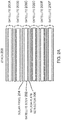
- FIG. 1 is a side view of a stackable pancake satellite 100 configured for being stacked within a payload fairing of a launch vehicle, according to one embodiment.
- the satellite 100 is a platform that includes a plurality of substantially flat sections, segments or panels 102, 104, 106 that are hingedly attached to each other, wherein the sections 102, 104, 106 are folded or rotated together for launch, and unfolded or rotated away from each other when deployed upon reaching orbit.
- the satellite 100 is a three-panel spacecraft.
- a first one of the sections 102 of the satellite 100 is a satellite body 102 having a first (top) flat side that acts as a thermal radiator 108 and a second (bottom) side opposite the first side that includes at least one antenna 110.
- the first section 102 may also include bus and payload units (not shown) mounted on or with the thermal radiator 108.
- the antenna 110 may comprise a multi-beam or phased array antenna 110 that include service and feeder-link arrays (not shown).
- a second one of the sections 104 of the satellite 100 includes at least one solar panel 104 attached adjacent to the first side of the satellite body 102 with a sun-active surface of the solar panel 104 pointing away from the satellite body 102 and towards the Sun, wherein light from the Sun is converted to electricity by one or more solar cells of the solar panel 104.
- a third one of the sections 106 of the satellite 100 includes at least one splash plate reflector 106 attached adjacent to the second side of the satellite body 102, wherein radio frequency (RF) signals 112 between Earth and the antenna 110 are reflected by the splash plate reflector 106.
- RF radio frequency
- the solar panel 104 When deployed, the solar panel 104 is rotated away from the first (top) side of the satellite body 102, so that the solar panel 104 is pointed towards the Sun, and the splash plate reflector 106 is rotated away from the second (bottom) side of the satellite body 102 to direct the signals 112 between the Earth and the antenna 110.
- top/bottom, up/down, and left/right used herein are relative terms that describe the relative position of the described elements. It is understood the satellite 100 may be at any orientation in space relative to an observer so that these terms may assume correspondingly different values.
- One or more mechanisms may be employed to keep the solar panel 104 pointed at the Sun, the splash plate reflector 106 pointed at Earth, and the thermal radiator 108 pointed into cold space. Preferably, all of this occurs while the satellite 100 follows a circular track on orbit to keep the signals 112 pointed at the Earth.
- FIG. 2A is a side view of a plurality of satellites 200a, 200b, 200c, 200d, 200e, and 200f, each of which includes a satellite body 202, at least one solar panel 204 and at least one splash plate reflector 206.
- the plurality of satellites 200a, 200b, 200c, 200d, 200e, and 200f are folded and arranged in a stack 208, so that they can be stowed for launch within a payload fairing of a launch vehicle (not shown).
- FIG. 2A shows six satellites 200a, 200b, 200c, 200d, 200e, and 200f arranged in the stack 208, this not intended to be limiting and any number of satellites 200 may be so arranged.
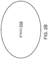
- FIG. 2B is a top view of the stack 208, illustrating that a periphery outline of the sections of the satellites 200a, 200b, 200c, 200d, 200e, and 200f when folded together is substantially oval or elliptical in shape.
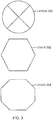
- FIG. 3 illustrates three top views of stacks 300, 302, and 304 of satellites, illustrating different possible cross-sections for the satellites, including substantially round 300, hexagonal 302, and octagonal 304 cross-sections.
- a periphery outline of the sections of each satellite, when folded together and stacked is round 300 or polygonal (e.g. hexagonal 302, octagonal 304, etc.) in shape. Other cross-sections may be used as well.
- FIG. 4A illustrates another example of a stackable pancake satellite 400, according to one embodiment.
- the satellite 400 includes a satellite body 402, two or more solar panels 404a, 404b, an antenna 406 comprising a C and Ka band array, and a splash plate reflector 408.
- the satellite body 402 has a cavity on the first side and a hollow region on the second side, such that, when folded together, the second one of the sections, comprising the two solar panels 404a, 404b, is folded and stowed within the hollow region.
- a thermal radiator (not shown) is also disposed within the hollow region.
- the antenna 406 is stored within the cavity of the satellite body 402.
- the third one of the sections, comprising the splash plate reflector 408, is stored adjacent to the antenna 406 in the cavity.
- each of the solar panels 404a, 404b includes a plurality of panel elements having substantially the same shape, and the plurality of panel elements are each folded upon each other to fit within the hollow region.
- each of the solar panels 404a, 404b comprises a multi-segmented array that is configured to be at least partially folded onto itself, prior to being stowed within the hollow region.
- a thruster 410 attached to an exterior panel of the satellite body 402.
- the satellite 400 may use "all electric propulsion" with one thruster 410 or any number of independent thrusters 410.
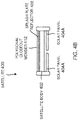
- FIG. 4B illustrates a side view of the satellite 400 of FIG. 4A , according to one embodiment.
- the relative positions of the satellite body 402, two solar panels 404a, 404b, and splash plate reflector 406, are shown when folded.
- a polygonal closeout member 412 covers the first side of the satellite body 402 surrounding the cavity.
- FIG. 4C illustrates a top view of the satellite 400 of FIG. 4A , according to one embodiment.
- the top view shows the hexagonal egg-crate structure 414 of the satellite body 402.
- FIG. 4D shows a plurality of satellites 400 in a stacked column configuration 416 disposed within a payload fairing 418 of a launch vehicle 420 prior to launch, according to one embodiment.
- the plurality of satellites 400 comprises at least one top satellite 400 disposed vertically on top of at least one bottom satellite 400 within the payload fairing 418 of the launch vehicle 420, wherein a structure bears launch loads for both the top and bottom satellites 400.
- each of the satellites 400 in the stack 416 is passively and serially dispensed from the payload fairing 418 of the launch vehicle 420 without the use of a dedicated dispensing apparatus, although active dispensing may also be used.
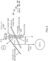
- FIG. 5 illustrates a deployed satellite 500 on orbit, according to one embodiment.
- the satellite 500 is comprised of a satellite body 502, solar panel 504 and splash plate reflector 506, wherein the solar panel 504 and splash plate reflector 506 are attached at different points on the satellite body 502.
- the satellite body 502 has a first (right) side that acts as a thermal radiator 508 and a second (left) side opposite the first side that includes an integrated antenna 510.
- Both the solar panel 504 and splash plate reflector 506 are shown deployed. When deployed, the solar panel 504 is rotated away from the satellite body 502, so that the solar panel 504 is pointed towards the Sun. Similarly, when deployed, the splash plate reflector 506 is rotated away from the satellite body 502 to direct the signals 512 between the Earth and the antenna 510.
- the arrows 514 at the top of the satellite body 502 indicate a yaw orientation about a center (nadir) axis of the satellite body 502 to keep the solar panel 504 pointed at the Sun (i.e., normal to the Sun on both axes), the splash plate reflector 506 pointed at Earth, and the thermal radiator 508 pointed away from the Sun into cold space.
- At least one thruster 516 is attached to one end of the satellite body 502, or another suitable location on the satellite body 502, to maintain orbit phasing.
- the thruster 516 is a single fixed thruster, although multiple smaller thrusters with an identical thrust direction are used in other embodiments.
- Orbit phasing is maintained by periodically rotating the satellite body 502 (e.g. with reaction wheels) so that a desired thrust angle for the thruster 516 is achieved, firing the thruster 516, and then restoring the satellite body 502 to its original position after firing the thruster 516. This process can be performed during orbit maintenance windows when there is no traffic demand (e.g., when a LEO satellite 500 is over the ocean and/or another satellite in a constellation can absorb extra capacity temporarily).
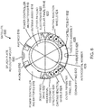
- FIG. 6 illustrates a cross-section view of one embodiment of the satellite 600, wherein the satellite body 602 has a hexagonal egg-crate structure 604, which is a load-bearing stacking structure.
- the body 602 includes a plurality of radially separated sections defined by a plurality of intercostal members 608, each surrounded by an outer perimeter panel 610, wherein the intercostal members 608 and adjacent outer perimeter panels 610 are joined by a plurality of elongated corner fittings 612.
- the various embedded systems stored in the radially separated sections include avionics 616, power controller and batteries 618, other payload electronics 620, solar panel drives 622, canting reaction wheels 624, thruster 626, thruster assembly 628 including tanks, and a splash plate reflector mount 630.
- Embodiments of the disclosure may be described in the context of a satellite or spacecraft fabricating method 700 as shown in FIG. 7 , wherein the resulting satellite or spacecraft is shown in FIG. 8 .
- exemplary method 700 may include specification and design 702 of the satellite 800 and material procurement 704.
- component and subassembly manufacturing 706 and system integration 708 of the satellite 800 takes place, which include fabricating the satellite 800, body 802, solar panels 804, splash plate reflector 806, and various systems 808 described herein.
- the satellite 800 may go through certification and delivery 710 in order to be placed in service 712.
- the satellite 800 may also be scheduled for maintenance and service 714 (which includes modification, reconfiguration, refurbishment, and so on), before being launched.
- a system integrator may include without limitation any number of spacecraft manufacturers and major-system subcontractors; a third party may include without limitation any number of venders, subcontractors, and suppliers; and an operator may be a satellite company, military entity, service organization, and so on.
- the satellite 800 fabricated by exemplary method 700 may include a body 802, solar panels 804, and splash plate reflector 806, as described in more detail above, with a plurality of systems 808.
- systems 808 include, but are not limited to, one or more of a propulsion system 810, an electrical system 812, a communications system 814, and a power system 816. Any number of other systems may be included.
- a number of benefits are derived from the stackable pancake satellite. Moreover, these benefits address DFMAT (Design for Manufacturing, Assembly, and Test) issues concerning the stackable pancake satellite.
- the stackable pancake satellite packages the maximum number of spacecraft into a fairing in the simplest manner (i.e. minimizing the number of deployments, folds, thermal interfaces, eliminating the need for heat pipes, etc.) to provide the lowest cost and highest reliability.
- the stackable pancake satellite configuration is enabled in part by a very modest propulsion system allowing the depth (e.g. height in the stack) of the spacecraft to be small. This is mostly due to a modest acceleration requirement.
- the stackable pancake satellite configuration is enhanced by the chosen configuration of small, electrically powered thrusters, but could have been realized with other thruster technologies including traditional chemical thrusters.
- the particular thruster technology was chosen for mass savings, using what should be a more readily produced thruster in high volume, and for ease of manufacturing at final integration.
Landscapes
- Engineering & Computer Science (AREA)
- Remote Sensing (AREA)
- Aviation & Aerospace Engineering (AREA)
- Physics & Mathematics (AREA)
- Astronomy & Astrophysics (AREA)
- General Physics & Mathematics (AREA)
- Combustion & Propulsion (AREA)
- Chemical & Material Sciences (AREA)
- Life Sciences & Earth Sciences (AREA)
- Sustainable Development (AREA)
- Radar, Positioning & Navigation (AREA)
- Health & Medical Sciences (AREA)
- Environmental & Geological Engineering (AREA)
- Environmental Sciences (AREA)
- General Health & Medical Sciences (AREA)
- Toxicology (AREA)
- Biodiversity & Conservation Biology (AREA)
- Details Of Aerials (AREA)
- Photovoltaic Devices (AREA)
- Aerials With Secondary Devices (AREA)
Abstract
Description
- The present invention relates to satellites, and in particular, to a stackable pancake satellite.
- Satellites and other spacecraft are used for a number of different purposes, including communication, navigation, observation and research. However, launching satellites into space is expensive.
- There are many factors that contribute to the high cost of launching satellites. Moreover, these factors constrain satellite design decisions. Two of the most fundamental constraints on satellite design decisions are the number of satellites supported by a launch vehicle, and the geometry of a payload fairing for the launch vehicle, which sets limits on the geometry of the satellites.
- Consequently, it is desirable if the satellite design supports storing more than one satellite on the launch vehicle. It is also desirable to have a satellite design that optimizes the geometry of the satellites for use within the geometry of the payload fairing.
- What is needed, then, are improved designs for satellites. The present invention satisfies this need.
- To overcome the limitations in the prior art described above, and to overcome other limitations that will become apparent upon reading and understanding the present specification, the present invention discloses a stacked satellite system, a method for launching the stacked satellite system, and a method for fabricating a satellite for use in the stacked satellite system.
- The stacked satellite system according to one example comprises a plurality of satellites configured for being stacked within a payload fairing of a launch vehicle. The satellites are disposed within the payload fairing of the launch vehicle in a stacked column configuration prior to launch. The plurality of satellites comprises at least one top satellite disposed vertically on top of at least one bottom satellite within the payload fairing of the launch vehicle, wherein a structure bears launch loads for both the top and bottom satellites. The satellites are passively dispensed from the payload fairing of the launch vehicle upon reaching orbit.
- Each of the satellites in one example includes a plurality of sections that are hingedly attached to each other, wherein the sections are folded or rotated together prior to launch, and unfolded or rotated away from each other when deployed upon reaching orbit. A periphery outline of the sections when folded together is oval, elliptical, round or polygonal in shape. The sections, when folded together, maintain a substantially flat profile.
- A first one of the sections is a satellite body having a first side that acts as a thermal radiator and a second side opposite the first side that includes at least one antenna, which in one embodiment comprises a multi-beam antenna. The first one of the sections also includes bus and payload units mounted on or with the thermal radiator.
- A second one of the sections includes at least one solar panel, and possibly two or more solar panels, attached adjacent to the first side of the satellite body, wherein light from the Sun is converted to electricity by the solar panel. In one embodiment, the solar panel comprises a multi-segmented array that is configured to be at least partially folded onto itself.
- A third one of the sections includes at least one splash plate reflector attached adjacent to the second side of the satellite body, wherein radio frequency signals between Earth and the antenna of the satellite are reflected by the splash plate reflector.
- The satellite body has a cavity on the first side and a hollow region on the second side, such that, when folded together, the solar panels are folded and stowed within the hollow region, the antenna is disposed within the cavity, and the splash plate reflector is stored adjacent to the antenna in the cavity.
- In one example, the thermal radiator and the solar panel are disposed within the hollow region, and the solar panel comprises a plurality of foldable solar arrays that, when folded, are enclosed within the hollow region. In another embodiment, the solar panel includes a plurality of panel elements having substantially the same shape, and the plurality of panel elements are each folded upon each other to fit within the hollow region.
- When deployed, the solar panel is rotated away from the first side of the satellite body, so that the solar panel is pointed towards the Sun, and the splash plate reflector is rotated away from the second side of the satellite body to direct the signals between the Earth and the antenna. One or more mechanisms are employed to keep the solar panel pointed at the Sun, the splash plate reflector pointed at the Earth, and the thermal radiator pointed into space.
- The method for launching a stacked satellite system in one example comprises stacking a plurality of satellites within a payload fairing of a launch vehicle, wherein each of the satellites is configured as described above, launching the plurality of satellites into orbit using the launch vehicle, and serially dispensing each of the plurality of satellites from the payload fairing of the launch vehicle upon reaching orbit. In one embodiment, the satellites are passively dispensed from the payload fairing of the launch vehicle upon reaching orbit.
- Orbit phasing is maintained with at least one thruster located on the satellite body by rotating the satellite body so that a desired thrust angle for the thruster is achieved, firing the thruster, and then restoring the satellite body to its original position after firing the thruster.
- Referring now to the drawings in which like terminology and reference numbers represent corresponding parts throughout:
-
FIG. 1 is a side view of a stackable pancake satellite configured for being stacked within a payload fairing of a launch vehicle, according to one embodiment. -
FIG. 2A is a side view of a plurality of satellites, according to one embodiment. -
FIG. 2B is a top view of a stack of satellites, according to one embodiment. -
FIG. 3 illustrates three top views of stacks of satellites, illustrating different possible cross-sections. -
FIG. 4A illustrates another example of a stackable pancake satellite, according to one embodiment. -
FIG. 4B illustrates a side view of the satellite ofFIG. 4A , according to one embodiment. -
FIG. 4C illustrates a top view of the satellite ofFIG. 4A , according to one embodiment. -
FIG. 4D shows a plurality of satellites in a stacked column configuration disposed within a payload fairing of a launch vehicle, according to one embodiment. -
FIG. 5 illustrates a deployed satellite on orbit, according to one embodiment. -
FIG. 6 illustrates a cross-section view of one embodiment of the satellite, wherein various embedded systems are located within separated sections in the satellite body. -
FIG. 7 is a flowchart of a satellite or spacecraft manufacturing method, according to one embodiment. -
FIG. 8 is an illustration of the components of a satellite or spacecraft manufactured inFIG. 7 , according to one embodiment. - In the following description of the preferred embodiment, reference is made to the accompanying drawings which form a part hereof, and in which is shown by way of illustration a specific embodiment in which the invention may be practiced. It is to be understood that other embodiments may be utilized and structural changes may be made without departing from the scope of the present invention.
- A stackable pancake satellite is comprised of a plurality of sections that are folded or rotated together into a flat configuration for launch, and are unfolded or rotated away from each other when deployed in orbit. The sections include a satellite body with a thermal radiator and an antenna, a solar cell panel, and a splash plate reflector for signals transmitted and received by the antenna. When folded into the flat configuration, a plurality of the satellites are stacked within a payload fairing of a launch vehicle.
-
FIG. 1 is a side view of astackable pancake satellite 100 configured for being stacked within a payload fairing of a launch vehicle, according to one embodiment. In this embodiment, thesatellite 100 is a platform that includes a plurality of substantially flat sections, segments orpanels sections satellite 100 is a three-panel spacecraft. - A first one of the
sections 102 of thesatellite 100 is asatellite body 102 having a first (top) flat side that acts as athermal radiator 108 and a second (bottom) side opposite the first side that includes at least oneantenna 110. Thefirst section 102 may also include bus and payload units (not shown) mounted on or with thethermal radiator 108. Theantenna 110 may comprise a multi-beam or phasedarray antenna 110 that include service and feeder-link arrays (not shown). - A second one of the sections 104 of the
satellite 100 includes at least one solar panel 104 attached adjacent to the first side of thesatellite body 102 with a sun-active surface of the solar panel 104 pointing away from thesatellite body 102 and towards the Sun, wherein light from the Sun is converted to electricity by one or more solar cells of the solar panel 104. - A third one of the
sections 106 of thesatellite 100 includes at least onesplash plate reflector 106 attached adjacent to the second side of thesatellite body 102, wherein radio frequency (RF) signals 112 between Earth and theantenna 110 are reflected by thesplash plate reflector 106. - When deployed, the solar panel 104 is rotated away from the first (top) side of the
satellite body 102, so that the solar panel 104 is pointed towards the Sun, and thesplash plate reflector 106 is rotated away from the second (bottom) side of thesatellite body 102 to direct thesignals 112 between the Earth and theantenna 110. - The terms top/bottom, up/down, and left/right used herein are relative terms that describe the relative position of the described elements. It is understood the
satellite 100 may be at any orientation in space relative to an observer so that these terms may assume correspondingly different values. - One or more mechanisms may be employed to keep the solar panel 104 pointed at the Sun, the
splash plate reflector 106 pointed at Earth, and thethermal radiator 108 pointed into cold space. Preferably, all of this occurs while thesatellite 100 follows a circular track on orbit to keep thesignals 112 pointed at the Earth. -
FIG. 2A is a side view of a plurality of satellites 200a, 200b, 200c, 200d, 200e, and 200f, each of which includes asatellite body 202, at least onesolar panel 204 and at least onesplash plate reflector 206. The plurality of satellites 200a, 200b, 200c, 200d, 200e, and 200f are folded and arranged in astack 208, so that they can be stowed for launch within a payload fairing of a launch vehicle (not shown). AlthoughFIG. 2A shows six satellites 200a, 200b, 200c, 200d, 200e, and 200f arranged in thestack 208, this not intended to be limiting and any number of satellites 200 may be so arranged. -
FIG. 2B is a top view of thestack 208, illustrating that a periphery outline of the sections of the satellites 200a, 200b, 200c, 200d, 200e, and 200f when folded together is substantially oval or elliptical in shape. -
FIG. 3 illustrates three top views ofstacks -
FIG. 4A illustrates another example of astackable pancake satellite 400, according to one embodiment. In this embodiment, thesatellite 400 includes asatellite body 402, two or more solar panels 404a, 404b, anantenna 406 comprising a C and Ka band array, and asplash plate reflector 408. Thesatellite body 402 has a cavity on the first side and a hollow region on the second side, such that, when folded together, the second one of the sections, comprising the two solar panels 404a, 404b, is folded and stowed within the hollow region. A thermal radiator (not shown) is also disposed within the hollow region. On an opposite side of thesatellite body 402, theantenna 406 is stored within the cavity of thesatellite body 402. The third one of the sections, comprising thesplash plate reflector 408, is stored adjacent to theantenna 406 in the cavity. - In one embodiment, each of the solar panels 404a, 404b includes a plurality of panel elements having substantially the same shape, and the plurality of panel elements are each folded upon each other to fit within the hollow region. In another embodiment, each of the solar panels 404a, 404b comprises a multi-segmented array that is configured to be at least partially folded onto itself, prior to being stowed within the hollow region.
- Also shown is a thruster 410 attached to an exterior panel of the
satellite body 402. In one embodiment, thesatellite 400 may use "all electric propulsion" with one thruster 410 or any number of independent thrusters 410. -
FIG. 4B illustrates a side view of thesatellite 400 ofFIG. 4A , according to one embodiment. The relative positions of thesatellite body 402, two solar panels 404a, 404b, and splashplate reflector 406, are shown when folded. Apolygonal closeout member 412 covers the first side of thesatellite body 402 surrounding the cavity. -
FIG. 4C illustrates a top view of thesatellite 400 ofFIG. 4A , according to one embodiment. The top view shows the hexagonal egg-crate structure 414 of thesatellite body 402. -
FIG. 4D shows a plurality ofsatellites 400 in a stackedcolumn configuration 416 disposed within a payload fairing 418 of alaunch vehicle 420 prior to launch, according to one embodiment. The plurality ofsatellites 400 comprises at least onetop satellite 400 disposed vertically on top of at least onebottom satellite 400 within the payload fairing 418 of thelaunch vehicle 420, wherein a structure bears launch loads for both the top andbottom satellites 400. Upon reaching orbit, each of thesatellites 400 in thestack 416 is passively and serially dispensed from the payload fairing 418 of thelaunch vehicle 420 without the use of a dedicated dispensing apparatus, although active dispensing may also be used. -
FIG. 5 illustrates a deployedsatellite 500 on orbit, according to one embodiment. In this embodiment, thesatellite 500 is comprised of asatellite body 502, solar panel 504 and splashplate reflector 506, wherein the solar panel 504 and splashplate reflector 506 are attached at different points on thesatellite body 502. Thesatellite body 502 has a first (right) side that acts as athermal radiator 508 and a second (left) side opposite the first side that includes anintegrated antenna 510. - Both the solar panel 504 and splash
plate reflector 506 are shown deployed. When deployed, the solar panel 504 is rotated away from thesatellite body 502, so that the solar panel 504 is pointed towards the Sun. Similarly, when deployed, thesplash plate reflector 506 is rotated away from thesatellite body 502 to direct thesignals 512 between the Earth and theantenna 510. - The
arrows 514 at the top of thesatellite body 502 indicate a yaw orientation about a center (nadir) axis of thesatellite body 502 to keep the solar panel 504 pointed at the Sun (i.e., normal to the Sun on both axes), thesplash plate reflector 506 pointed at Earth, and thethermal radiator 508 pointed away from the Sun into cold space. - In addition, at least one thruster 516 is attached to one end of the
satellite body 502, or another suitable location on thesatellite body 502, to maintain orbit phasing. In one embodiment, the thruster 516 is a single fixed thruster, although multiple smaller thrusters with an identical thrust direction are used in other embodiments. Orbit phasing is maintained by periodically rotating the satellite body 502 (e.g. with reaction wheels) so that a desired thrust angle for the thruster 516 is achieved, firing the thruster 516, and then restoring thesatellite body 502 to its original position after firing the thruster 516. This process can be performed during orbit maintenance windows when there is no traffic demand (e.g., when aLEO satellite 500 is over the ocean and/or another satellite in a constellation can absorb extra capacity temporarily). -
FIG. 6 illustrates a cross-section view of one embodiment of thesatellite 600, wherein thesatellite body 602 has a hexagonal egg-crate structure 604, which is a load-bearing stacking structure. Thebody 602 includes a plurality of radially separated sections defined by a plurality ofintercostal members 608, each surrounded by an outer perimeter panel 610, wherein theintercostal members 608 and adjacent outer perimeter panels 610 are joined by a plurality ofelongated corner fittings 612. The various embedded systems stored in the radially separated sections includeavionics 616, power controller andbatteries 618, other payload electronics 620, solar panel drives 622, cantingreaction wheels 624, thruster 626,thruster assembly 628 including tanks, and a splashplate reflector mount 630. When thesatellite 600 is stacked, with atop satellite 600 disposed vertically on abottom satellite 600, the plurality ofelongated corner fittings 612 for thebottom satellite 600 bear the loads for both the top andbottom satellites 600. - Embodiments of the disclosure may be described in the context of a satellite or
spacecraft fabricating method 700 as shown inFIG. 7 , wherein the resulting satellite or spacecraft is shown inFIG. 8 . - As illustrated in
FIG. 7 , during pre-production,exemplary method 700 may include specification anddesign 702 of thesatellite 800 andmaterial procurement 704. During production, component andsubassembly manufacturing 706 andsystem integration 708 of thesatellite 800 takes place, which include fabricating thesatellite 800,body 802,solar panels 804,splash plate reflector 806, andvarious systems 808 described herein. Thereafter, thesatellite 800 may go through certification anddelivery 710 in order to be placed inservice 712. Thesatellite 800 may also be scheduled for maintenance and service 714 (which includes modification, reconfiguration, refurbishment, and so on), before being launched. - Each of the processes of
method 700 may be performed or carried out by a system integrator, a third party, and/or an operator (e.g., a customer). For the purposes of this description, a system integrator may include without limitation any number of spacecraft manufacturers and major-system subcontractors; a third party may include without limitation any number of venders, subcontractors, and suppliers; and an operator may be a satellite company, military entity, service organization, and so on. - As shown in
FIG. 8 , thesatellite 800 fabricated byexemplary method 700 may include abody 802,solar panels 804, and splashplate reflector 806, as described in more detail above, with a plurality ofsystems 808. Examples ofsuch systems 808 include, but are not limited to, one or more of apropulsion system 810, anelectrical system 812, acommunications system 814, and apower system 816. Any number of other systems may be included. - A number of benefits are derived from the stackable pancake satellite. Moreover, these benefits address DFMAT (Design for Manufacturing, Assembly, and Test) issues concerning the stackable pancake satellite.
- For example, some of those benefits include:
- The systems, sub-systems, sections, panels, units, and components are manufactured and tested in volume to reduce cost.
- The thermal radiator provides a direct path to radiate waste heat to space without the need for complex and mass heavy heat pipes.
- Sections or panels may be built and tested in the best respective factories on production lines:
- ∘ Functional and performance testing is minimal (possibly ∼1 hour per spacecraft); and
- ∘ Environmental and burn-in test when deemed appropriate.
- Sections or panels assembled and stacked for launch:
- ∘ Potentially at launch site; and
- ∘ Minimal spacecraft level testing other than interconnection and mechanism validation (possibly ∼1 hour per spacecraft).
- Multiple satellites can be launched at one time, thereby reducing the launch costs per satellite.
- A number of basic problems are solved by of the stackable pancake satellite. For example, the stackable pancake satellite packages the maximum number of spacecraft into a fairing in the simplest manner (i.e. minimizing the number of deployments, folds, thermal interfaces, eliminating the need for heat pipes, etc.) to provide the lowest cost and highest reliability.
- This is especially true when the performance of the spacecraft is driven by the area of three critical elements: the area of the payload aperture, the area of the thermal radiator for waste heat dissipation, and the area of the solar panels for power generation.
- While propulsion is an important issue, it is not as significant as these three critical elements. The stackable pancake satellite configuration is enabled in part by a very modest propulsion system allowing the depth (e.g. height in the stack) of the spacecraft to be small. This is mostly due to a modest acceleration requirement.
- The stackable pancake satellite configuration is enhanced by the chosen configuration of small, electrically powered thrusters, but could have been realized with other thruster technologies including traditional chemical thrusters. The particular thruster technology was chosen for mass savings, using what should be a more readily produced thruster in high volume, and for ease of manufacturing at final integration.
- Other configurations may not be packaged as efficiently in the fairing and/or wind up with complex deployments to achieve the desired areas; hence, the virtue of the pancake satellite configuration.
- Throughout the development, optimization for low earth orbit (LEO), with altitudes from ∼500 kilometers (km) to ∼1500 km, was a central focus. However, the stackable pancake satellite may be inserted into all inclinations from virtually any launch site and using any launch vehicle throughout.
- Illustrative, non-exclusive examples of inventive subject matter according to the present invention are described in the clauses below:
- A1. According to an aspect of the present disclosure there is provided a stacked satellite system, comprising:
- a plurality of
satellites 100 configured for being stacked within a payload fairing 418 of alaunch vehicle 420; - each of the
satellites 100 includes a plurality ofsections - a first one of the
sections 102 is asatellite body 102 having a first side that acts as athermal radiator 108 and a second side opposite the first side that includes at least oneantenna 110; - a second one of the sections 104 includes at least one solar panel 104 attached adjacent to the first side of the
satellite body 102, wherein light from the Sun is converted to electricity by the solar panel 104; and - a third one of the
sections 106 includes at least onesplash plate reflector 106 attached adjacent to the second side of thesatellite body 102, wherein radio frequency signals between Earth and theantenna 110 of thesatellite 100 are reflected by thesplash plate reflector 106; - when deployed, the solar panel 104 is rotated away from the first side of the
satellite body 102, so that the solar panel 104 is pointed towards the Sun, and thesplash plate reflector 106 is rotated away from the second side of thesatellite body 102 to direct the signals between the Earth and theantenna 110.
- a plurality of
- A2. Advantageously the system of clause A1, wherein a periphery outline of the
sections - A3. Advantageously the system of clauses A1 or A2, wherein the
sections - A4. Advantageously the system of any one of clauses A1 to A3, wherein the
satellite body 402 has a cavity on the first side and a hollow region on the second side, such that, when folded together, the at least one solar panels 404a is folded and stowed within the hollow region, theantenna 406 is disposed within the cavity, and thesplash plate reflector 408 is stored adjacent to the antenna in the cavity. - A5. Advantageously the system of clause A4, further comprising:
- a
polygonal closeout member 412 covers the first side of thesatellite body 402 surrounding the cavity; and - the
thermal radiator 108 and the at least one solar panel 404a are disposed within the hollow region, and the solar panel 404a comprises a plurality of foldable solar arrays that, when folded, are enclosed within the hollow region.
- a
- A6. Advantageously the system of clauses A4 or A5, wherein the at least one solar panel 404a includes a plurality of panel elements having substantially the same shape, and the plurality of panel elements are each folded upon each other to fit within the hollow region.
- A7. Advantageously the system of any one of clauses A1 to A6, wherein the at least one solar panel comprises two or more solar panels 404a, 404b.
- A8. Advantageously the system of any one of clauses A1 to A7, wherein the at least one solar panel 404a comprises a multi-segmented array that is configured to be at least partially folded onto itself.
- A9. Advantageously the system of any one of clauses A1 to A8, wherein the satellites are disposed within the payload fairing 418 of the
launch vehicle 420 in a stacked column configuration prior to launch. - A10. Advantageously he system of any one of clauses A1 to A9, wherein the plurality of
satellites 400 comprises at least onetop satellite 400 disposed vertically on top of at least onebottom satellite 400 within the payload fairing 418 of thelaunch vehicle 420, wherein a structure bears launch loads for both the top andbottom satellites 400. - A11. Advantageously the system of any one of clauses A1 to A10, wherein the
satellites 400 are passively dispensed from the payload fairing 418 of thelaunch vehicle 420 upon reaching orbit. - A12. Advantageously the system of any one of clauses A1 to A11, wherein the first one of the sections includes bus and payload units mounted on or with the
thermal radiator 108. - A13. Advantageously the system of any one of clauses A1 to A12, wherein the
antenna 110 comprises a multi-beam antenna. - A14. Advantageously the system of any one of clauses A1 to A13, wherein at least one thruster 410 is attached to the
satellite body 402 to maintain orbit phasing. - A15. Advantageously the system of any one of clauses A1 to A14, wherein one or more mechanisms are employed to keep the solar panel 104 pointed at the Sun, the
splash plate reflector 106 pointed at the Earth, and thethermal radiator 108 pointed into space. - B16. According to a further aspect of the present disclosure there is provided a method for launching a stacked satellite system, comprising:
stacking a plurality ofsatellites 100 within a payload fairing 418 of alaunch vehicle 420, wherein:- each of the
satellites 100 includes a plurality ofsections sections - a first one of the
sections 102 is asatellite body 102 having a first side that acts as athermal radiator 108 and a second side opposite the first side that includes at least oneantenna 110; - a second one of the sections 104 includes at least one solar panel 104 attached adjacent to the first side of the
satellite body 102, wherein light from the Sun is converted to electricity by the solar panel 104; and - a third one of the
sections 106 includes at least onesplash plate reflector 106 attached adjacent to the second side of thesatellite body 102, wherein radio frequency signals between Earth and theantenna 110 of the satellite are reflected by thesplash plate reflector 106; - launching the plurality of
satellites 100 into orbit using thelaunch vehicle 420; and - serially dispensing each of the plurality of
satellites 100 from the payload fairing 418 of thelaunch vehicle 420 upon reaching orbit, such that, when each of thesatellites 100 is deployed, the second section 104 is rotated away from the first side of thesatellite body 102 so that the solar panel 104 is pointed towards the Sun, and thethird section 106 is rotated away from the second side of thesatellite body 102 so that thesplash plate reflector 106 directs the radio frequency signals between Earth and theantenna 110.
- each of the
- B17. Advantageously the method of clause B16, wherein a periphery outline of the
sections - B18. Advantageously the method of clauses B16 or B17, wherein the
sections - B19. Advantageously the method of any one of clauses B16 to B18, wherein the
satellite body 402 has a cavity on the first side and a hollow region on the second side, such that, when folded together, the at least one solar panels 404a is folded and stowed within the hollow region, theantenna 406 is disposed within the cavity, and thesplash plate reflector 408 is stored adjacent to theantenna 406 in the cavity. - B20. Advantageously the method of clause B19, wherein:
- a
polygonal closeout member 412 covers the first side of thesatellite body 402 surrounding the cavity; and - the
thermal radiator 108 and the at least one solar panel 404a are disposed within the hollow region, and the solar panel 404a comprises a plurality of foldable solar arrays that, when folded, are enclosed within the hollow region.
- a
- B21. Advantageously the method of any one of clauses B16 to B20, wherein the plurality of
satellites 400 comprises at least onetop satellite 400 disposed vertically on top of at least onebottom satellite 400 within the payload fairing 418 of thelaunch vehicle 420, wherein a structure bears launch loads for both the top andbottom satellites 400. - B22. Advantageously the method of any one of clauses B16 to B 21, wherein the
satellites 400 are passively dispensed from the payload fairing 418 of thelaunch vehicle 420 upon reaching orbit. - B23. Advantageously the method of any one of clauses B16 to B22, wherein one or more mechanisms are employed to keep the solar panel 104 pointed at the Sun, the
splash plate reflector 106 pointed at the Earth, and thethermal radiator 108 pointed into space, upon reaching orbit. - B24. Advantageously the method of any one of clauses B16 to B23, wherein orbit phasing is maintained with a thruster 410 located on the
satellite body 402 by rotating thesatellite body 402 so that a desired thrust angle for the thruster 410 is achieved, firing the thruster 410, and then restoring thesatellite body 402 to its original position after firing the thruster 410. - C25. According to yet a further aspect of the present disclosure there is provided a method for fabricating a
satellite 100 that is configured for being stacked with one or moreother satellites 100 of the same configuration within a payload fairing 418 of alaunch vehicle 420 in accordance with the stacked satellite system of clause A1. -
Clause 1. A stacked satellite system, comprising:- a plurality of satellites (100) configured for being stacked within a payload fairing (418) of a launch vehicle (420);
- each of the satellites (100) includes a plurality of sections (102, 104, 106) that are hingedly attached to each other, wherein the sections are folded or rotated together prior to launch, and unfolded or rotated away from each other when deployed upon reaching orbit;
- a first one of the sections (102) is a satellite body (102) having a first side that acts as a thermal radiator (108) and a second side opposite the first side that includes at least one antenna (110);
- a second one of the sections (104) includes at least one solar panel (104) attached adjacent to the first side of the satellite body (102), wherein light from the Sun is converted to electricity by the solar panel (104); and
- a third one of the sections (106) includes at least one splash plate reflector (106) attached adjacent to the second side of the satellite body (102), wherein radio frequency signals between Earth and the antenna (110) of the satellite (100) are reflected by the splash plate reflector (106);
- when deployed, the solar panel (104) is rotated away from the first side of the satellite body (102), so that the solar panel (104) is pointed towards the Sun, and the splash plate reflector (106) is rotated away from the second side of the satellite body (102) to direct the signals between the Earth and the antenna (110).
- Clause 2. The system of
clause 1, wherein a periphery outline of the sections (102, 104, 106) when folded together is oval, elliptical, round or polygonal in shape. - Clause 3. The system of
clauses 1 or 2, wherein the sections (102, 104, 106), when folded together, maintain a substantially flat profile. - Clause 4. The system of any one of
clauses 1 to 3, wherein the satellite body (402) has a cavity on the first side and a hollow region on the second side, such that, when folded together, the at least one solar panels (404a) is folded and stowed within the hollow region, the antenna (406) is disposed within the cavity, and the splash plate reflector (408) is stored adjacent to the antenna in the cavity. - Clause 5. The system of clause 4, further comprising:
- a polygonal closeout member (412) covers the first side of the satellite body (402) surrounding the cavity; and
- the thermal radiator (108) and the at least one solar panel (404a) are disposed within the hollow region, and the solar panel (404a) comprises a plurality of foldable solar arrays that, when folded, are enclosed within the hollow region.
- Clause 6. The system of clause 4, wherein the at least one solar panel (404a) includes a plurality of panel elements having substantially the same shape, and the plurality of panel elements are each folded upon each other to fit within the hollow region.
- Clause 7. The system of any one of
clauses 1 to 6, wherein the at least one solar panel (404a) comprises a multi-segmented array that is configured to be at least partially folded onto itself. - Clause 8. A method for launching a stacked satellite system, comprising:
- stacking a plurality of satellites (100) within a payload fairing (418) of a launch vehicle (420), wherein:
- each of the satellites (100) includes a plurality of sections (102, 104, 106) that are hingedly attached to each other, wherein the sections (102, 104, 106) are folded or rotated together prior to launch, and unfolded or rotated away from each other when deployed upon reaching orbit;
- a first one of the sections (102) is a satellite body (102) having a first side that acts as a thermal radiator (108) and a second side opposite the first side that includes at least one antenna (110);
- a second one of the sections (104) includes at least one solar panel (104) attached adjacent to the first side of the satellite body (102), wherein light from the Sun is converted to electricity by the solar panel (104); and
- a third one of the sections (106) includes at least one splash plate reflector (106) attached adjacent to the second side of the satellite body (102), wherein radio frequency signals between Earth and the antenna (110) of the satellite are reflected by the splash plate reflector (106);
- launching the plurality of satellites (100) into orbit using the launch vehicle (420); and
- serially dispensing each of the plurality of satellites (100) from the payload fairing (418) of the launch vehicle (420) upon reaching orbit, such that, when each of the satellites (100) is deployed, the second section (104) is rotated away from the first side of the satellite body (102) so that the solar panel (104) is pointed towards the Sun, and the third section (106) is rotated away from the second side of the satellite body (102) so that the splash plate reflector (106) directs the radio frequency signals between Earth and the antenna (110).
- stacking a plurality of satellites (100) within a payload fairing (418) of a launch vehicle (420), wherein:
- Clause 9. The method of clause 8, wherein a periphery outline of the sections (102, 104, 106) when folded together is oval, elliptical, round or polygonal in shape.
- Clause 10. The method of clauses 8 or 9, wherein the sections (102, 104, 106), when folded together, maintain a substantially flat profile.
- Clause 11. The method of clauses 8 to 10, wherein the satellite body (402) has a cavity on the first side and a hollow region on the second side, such that, when folded together, the at least one solar panels (404a) is folded and stowed within the hollow region, the antenna (406) is disposed within the cavity, and the splash plate reflector (408) is stored adjacent to the antenna (406) in the cavity.
- Clause 12. The method of clause 11, wherein:
- a polygonal closeout member (412) covers the first side of the satellite body (402) surrounding the cavity; and
- the thermal radiator (108) and the at least one solar panel (404a) are disposed within the hollow region, and the solar panel (404a) comprises a plurality of foldable solar arrays that, when folded, are enclosed within the hollow region.
- Clause 13. The method of any one of clauses 8 to 12, wherein the plurality of satellites (400) comprises at least one top satellite (400) disposed vertically on top of at least one bottom satellite (400) within the payload fairing (418) of the launch vehicle (420), wherein a structure bears launch loads for both the top and bottom satellites (400).
- Clause 14. The method of any one of clauses 8 to 13, wherein one or more mechanisms are employed to keep the solar panel (104) pointed at the Sun, the splash plate reflector (106) pointed at the Earth, and the thermal radiator (108) pointed into space, upon reaching orbit.
- Clause 15. A method for fabricating a satellite (100) that is configured for being stacked with one or more other satellites (100) of the same configuration within a payload fairing (418) of a launch vehicle (420) in accordance with the stacked satellite system of
claim 1. - The description of the different embodiments set forth above has been presented for purposes of illustration and description, and is not intended to be exhaustive or limited to the embodiments in the form disclosed. Many modifications and variations will be apparent to those of ordinary skill in the art. It is intended that the scope of the invention be limited not by this detailed description, but rather by the claims appended hereto.
Claims (15)
- A stacked satellite system, comprising:a plurality of satellites (100) configured for being stacked for launch and unfolded when deployed;each of the satellites (100) includes a plurality of sections (102, 104, 106) that are hingedly attached to each other, a first one of the sections (102) is a satellite body (102) having a first side that acts as a thermal radiator (108) and a second side opposite the first side that includes at least one antenna (110);a second one of the sections (104) includes at least one solar panel (104) attached to the first side of the satellite body (102); anda third one of the sections (106) includes at least one splash plate reflector (106) for reflecting signals between Earth and the antenna, the splash plate reflector being attached to the second side of the satellite body (102),wherein, when deployed, the solar panel (104) is rotated away from the satellite body (102), so that the solar panel (104) is pointed towards the Sun, and the splash plate reflector (106) is rotated away from the satellite body (102) to direct the signals between the Earth and the antenna (110).
- The system of claim 1, wherein a periphery outline of the sections (102, 104, 106) when folded together is oval, elliptical, round or polygonal in shape.
- The system of claims 1 or 2, wherein the sections (102, 104, 106), when folded together, maintain a substantially flat profile.
- The system of any one of claims 1 to 3, wherein the satellite body (402) has a cavity on the first side and a hollow region on the second side, such that, when folded together, the at least one solar panels (404a) is folded and stowed within the hollow region, the antenna (406) is disposed within the cavity, and the splash plate reflector (408) is stored adjacent to the antenna in the cavity.
- The system of claim 4, further comprising:a polygonal closeout member (412) covers the first side of the satellite body (402) surrounding the cavity; andthe thermal radiator (108) and the at least one solar panel (404a) are disposed within the hollow region, and the solar panel (404a) comprises a plurality of foldable solar arrays that, when folded, are enclosed within the hollow region.
- The system of claim 4, wherein the at least one solar panel (404a) includes a plurality of panel elements having substantially the same shape, and the plurality of panel elements are each folded upon each other to fit within the hollow region.
- The system of any one of claims 1 to 6, wherein the at least one solar panel (404a) comprises a multi-segmented array that is configured to be at least partially folded onto itself.
- A method for launching a stacked satellite system, comprising:stacking a plurality of satellites (100) for launch, wherein:each of the satellites (100) includes a plurality of sections (102, 104, 106) that are hingedly attached to each other, wherein the sections (102, 104, 106) are folded or rotated together prior to launch, and unfolded or rotated away from each other when deployed;a first one of the sections (102) is a satellite body (102) having a first side that acts as a thermal radiator (108) and a second side opposite the first side that includes at least one antenna (110);a second one of the sections (104) includes at least one solar panel (104) attached adjacent to the first side of the satellite body (102); anda third one of the sections (106) includes at least one splash plate reflector (106) for reflecting signals between Earth and the antenna, the splash plate reflector being attached to the second side of the satellite body (102);launching the plurality of satellites (100); anddispensing each of the plurality of satellites (100) such that, when each of the satellites (100) is deployed, the second section (104) is rotated away from the satellite body (102) so that the solar panel (104) is pointed towards the Sun, and the third section (106) is rotated away from of the satellite body (102) to direct the signals between Earth and the antenna (110).
- The method of claim 8, wherein a periphery outline of the sections (102, 104, 106) when folded together is oval, elliptical, round or polygonal in shape.
- The method of claims 8 or 9, wherein the sections (102, 104, 106), when folded together, maintain a substantially flat profile.
- The method of claims 8 to 10, wherein the satellite body (402) has a cavity on the first side and a hollow region on the second side, such that, when folded together, the at least one solar panels (404a) is folded and stowed within the hollow region, the antenna (406) is disposed within the cavity, and the splash plate reflector (408) is stored adjacent to the antenna (406) in the cavity.
- The method of claim 11, wherein:a polygonal closeout member (412) covers the first side of the satellite body (402) surrounding the cavity; andthe thermal radiator (108) and the at least one solar panel (404a) are disposed within the hollow region, and the solar panel (404a) comprises a plurality of foldable solar arrays that, when folded, are enclosed within the hollow region.
- The method of any one of claims 8 to 12, wherein the plurality of satellites (400) comprises at least one top satellite (400) disposed vertically on top of at least one bottom satellite (400) within a payload fairing (418) of a launch vehicle (420), wherein a structure bears launch loads for both the top and bottom satellites (400).
- The method of any one of claims 8 to 13, wherein one or more mechanisms are employed to keep the solar panel (104) pointed at the Sun, the splash plate reflector (106) pointed at the Earth, and the thermal radiator (108) pointed into space, upon reaching orbit.
- A method for fabricating a satellite (100) that is configured for being stacked with one or more other satellites (100) of the same configuration within a payload fairing (418) of a launch vehicle (420) in accordance with the stacked satellite system of claim 1.
Applications Claiming Priority (3)
| Application Number | Priority Date | Filing Date | Title |
|---|---|---|---|
| US201662347751P | 2016-06-09 | 2016-06-09 | |
| US15/366,698 US10532830B2 (en) | 2016-06-09 | 2016-12-01 | Stackable pancake satellite |
| EP17171562.6A EP3254973B1 (en) | 2016-06-09 | 2017-05-17 | Stackable pancake satellite |
Related Parent Applications (2)
| Application Number | Title | Priority Date | Filing Date |
|---|---|---|---|
| EP17171562.6A Division-Into EP3254973B1 (en) | 2016-06-09 | 2017-05-17 | Stackable pancake satellite |
| EP17171562.6A Division EP3254973B1 (en) | 2016-06-09 | 2017-05-17 | Stackable pancake satellite |
Publications (2)
| Publication Number | Publication Date |
|---|---|
| EP3569508A1 true EP3569508A1 (en) | 2019-11-20 |
| EP3569508B1 EP3569508B1 (en) | 2022-01-26 |
Family
ID=58745071
Family Applications (2)
| Application Number | Title | Priority Date | Filing Date |
|---|---|---|---|
| EP19176307.7A Active EP3569508B1 (en) | 2016-06-09 | 2017-05-17 | Stackable pancake satellite |
| EP17171562.6A Active EP3254973B1 (en) | 2016-06-09 | 2017-05-17 | Stackable pancake satellite |
Family Applications After (1)
| Application Number | Title | Priority Date | Filing Date |
|---|---|---|---|
| EP17171562.6A Active EP3254973B1 (en) | 2016-06-09 | 2017-05-17 | Stackable pancake satellite |
Country Status (6)
| Country | Link |
|---|---|
| US (2) | US10532830B2 (en) |
| EP (2) | EP3569508B1 (en) |
| JP (1) | JP6858649B2 (en) |
| CN (1) | CN107487457B (en) |
| CA (1) | CA2964003C (en) |
| RU (1) | RU2736893C2 (en) |
Cited By (1)
| Publication number | Priority date | Publication date | Assignee | Title |
|---|---|---|---|---|
| US20190315501A1 (en) * | 2018-04-17 | 2019-10-17 | Raytheon Company | Thermally-enhanced and deployable structures |
Families Citing this family (32)
| Publication number | Priority date | Publication date | Assignee | Title |
|---|---|---|---|---|
| US10532830B2 (en) * | 2016-06-09 | 2020-01-14 | The Boeing Company | Stackable pancake satellite |
| US10351268B2 (en) * | 2016-12-08 | 2019-07-16 | The Boeing Company | Systems and methods for deploying spacecraft |
| US20180201393A1 (en) * | 2017-01-18 | 2018-07-19 | Cory Lawrence Johns | Apparatus and method for packaging and deploying large structures using hexagons |
| RO133557B1 (en) | 2018-02-19 | 2020-11-27 | Mazarom Impex S.R.L. | Artificial satellite with reduced size |
| CN109625339B (en) * | 2018-12-29 | 2022-04-15 | 西北工业大学 | Micro-nano satellite separation device capable of controlling rotation angular velocity |
| CN110015444A (en) * | 2019-03-29 | 2019-07-16 | 上海卫星工程研究所 | Middle zero dip composition aperture radar satellite configuration of high orbit |
| CN113120256A (en) * | 2019-12-30 | 2021-07-16 | 北京九天微星科技发展有限公司 | Low-orbit satellite with flat structure |
| CN111332496B (en) * | 2020-03-03 | 2023-05-05 | 陕西智星空间科技有限公司 | Satellite transmitting method and satellite fixing device |
| CN111332495B (en) * | 2020-03-03 | 2023-08-08 | 陕西智星空间科技有限公司 | Plate-shaped satellite assembly and transmitting method thereof |
| CN111762338A (en) * | 2020-05-25 | 2020-10-13 | 航天科工空间工程发展有限公司 | Folding flat satellite structure |
| US11492147B2 (en) * | 2020-07-30 | 2022-11-08 | The Aerospace Corporation | Stackable satellite structure and deployment method |
| CN112265656B (en) * | 2020-09-23 | 2021-12-07 | 北京空间飞行器总体设计部 | Packaging and containing type on-orbit assembly device and method for long-length antenna |
| KR102520001B1 (en) * | 2021-01-22 | 2023-04-12 | 주식회사 솔탑 | Integrated SAR Satellite |
| CN113232892B (en) * | 2021-04-30 | 2023-02-03 | 中国空间技术研究院 | One-rocket-multi-satellite-launching foldable and expandable modular stacked satellite configuration |
| US12362453B2 (en) * | 2021-07-21 | 2025-07-15 | Molex, Llc | Solar mitigation solutions for electronic equipment |
| CN113682495B (en) * | 2021-08-27 | 2022-09-23 | 中国空间技术研究院 | A space thin-film satellite integrating communication transmission and debris removal |
| US12515822B1 (en) * | 2021-09-17 | 2026-01-06 | Lockheed Martin Corporation | Satellite thermal transport system for earth-facing components |
| CN113734467A (en) * | 2021-11-05 | 2021-12-03 | 北京微焓科技有限公司 | Satellite solar wing |
| CN114148546B (en) * | 2021-11-17 | 2023-08-18 | 北京九天微星科技发展有限公司 | a satellite configuration |
| US12227313B2 (en) | 2021-11-30 | 2025-02-18 | Maxar Space Llc | Fold-out satellite with integrated radiator panel |
| AU2022400463A1 (en) * | 2021-12-02 | 2024-05-23 | Fleet Space Technologies Pty Ltd | Small leo satellite systems and methods |
| FR3130393B1 (en) * | 2021-12-09 | 2023-11-03 | Thales Sa | TTC antenna arrangement for flat satellite |
| US12017806B2 (en) | 2022-01-21 | 2024-06-25 | Maxar Space Llc | Satellite with modular radiator panels |
| WO2023161714A1 (en) * | 2022-02-25 | 2023-08-31 | Network Access Associates | System and method for deployment of space vehicle solar array |
| CN114313311B (en) * | 2022-03-04 | 2022-05-27 | 中国人民解放军战略支援部队航天工程大学 | Topological structure of multi-body allosteric satellite |
| US20250197033A1 (en) * | 2022-04-12 | 2025-06-19 | Ascendarc, Inc. | A Satellite Designed to be Stacked and Launched in Groups |
| CN116443279A (en) * | 2023-05-08 | 2023-07-18 | 北京中科宇航技术有限公司 | Stacked flat satellite spin-polishing separation method and system |
| US12214909B1 (en) | 2023-07-17 | 2025-02-04 | Maxar Space Llc | Dispensing hinge assembly |
| US12600497B2 (en) | 2023-07-17 | 2026-04-14 | Maxar Space Llc | Linked spacecraft dispensing |
| CN117341989A (en) * | 2023-11-03 | 2024-01-05 | 银河航天科技(安徽)有限公司 | A stackable flat-panel satellite and its use method |
| CN117895222B (en) * | 2024-03-14 | 2024-06-14 | 鹏城实验室 | Reflection array unit and reflection array |
| CA3280365A1 (en) * | 2024-08-02 | 2026-03-01 | Macdonald, Dettwiler And Associates Corporation | Integrated array element structure |
Citations (5)
| Publication number | Priority date | Publication date | Assignee | Title |
|---|---|---|---|---|
| US5052640A (en) * | 1989-08-29 | 1991-10-01 | Hughes Aircraft Company | Spacecraft design enabling the flat packing of multiple spacecraft in the launch vehicle |
| US5522569A (en) * | 1994-02-04 | 1996-06-04 | Orbital Sciences Corporation | Satellite having a stackable configuration |
| US5527001A (en) * | 1993-06-11 | 1996-06-18 | Teledesic Corporation | Modular communication satellite |
| US5642122A (en) * | 1991-11-08 | 1997-06-24 | Teledesic Corporation | Spacecraft antennas and beam steering methods for satellite communciation system |
| US20010045494A1 (en) * | 2000-01-07 | 2001-11-29 | Higgins Robert P. | Method for limiting interference between satellite communications systems |
Family Cites Families (26)
| Publication number | Priority date | Publication date | Assignee | Title |
|---|---|---|---|---|
| FR2152364A1 (en) * | 1971-08-06 | 1973-04-27 | Scheel Henning | |
| US4811034A (en) * | 1987-07-31 | 1989-03-07 | Trw Inc. | Stowable reflector |
| US4854526A (en) * | 1987-08-10 | 1989-08-08 | Hughes Aircraft Company | Spacecraft design enabling the compact nesting of multiple spacecraft in the launch vehicle |
| US5199672A (en) * | 1990-05-25 | 1993-04-06 | Orbital Sciences Corporation | Method and apparatus for deploying a satellite network |
| US5386953A (en) * | 1991-11-08 | 1995-02-07 | Calling Communications Corporation | Spacecraft designs for satellite communication system |
| EP0631342A1 (en) * | 1993-06-23 | 1994-12-28 | Ail Systems, Inc. | Antenna mirror scanner with constant polarization characteristics |
| US5673459A (en) * | 1994-09-28 | 1997-10-07 | Space Systems/Loral, Inc. | Deployment hinge apparatus |
| DE19818240C2 (en) * | 1998-04-23 | 2000-06-29 | Daimler Chrysler Ag | Reflector and reflector element for antennas for use in space, and method for unfolding a reflector |
| US6543724B1 (en) * | 1999-07-22 | 2003-04-08 | Lockheed Martin Corporation | Miniature satellite design |
| US6536712B1 (en) * | 1999-07-22 | 2003-03-25 | Lockhead Martin Corporation | Inflatable satellite |
| US6568638B1 (en) * | 2000-11-07 | 2003-05-27 | Lockheed Martin Corporation | Modular spacecraft structure |
| FR2853624B1 (en) * | 2003-04-14 | 2005-06-10 | Eads Launch Vehicles | SET OF ELEMENTS, FOLDABLE AND DEPLOYABLE, MOUNTED ON BOARD A SPACE ENGINE |
| US7478782B2 (en) * | 2004-11-16 | 2009-01-20 | The Boeing Company | System and method incorporating adaptive and reconfigurable cells |
| CN101582715B (en) * | 2006-09-26 | 2013-05-15 | 维尔塞特公司 | Improved spot beam satellite system |
| CN101117927A (en) * | 2007-08-23 | 2008-02-06 | 陈久斌 | Nuclear reactor and flying saucer made by it |
| CN101519126A (en) * | 2009-04-14 | 2009-09-02 | 哈尔滨工业大学 | Lunar rover release mechanism of vertical elevating type |
| US8179313B1 (en) * | 2009-05-22 | 2012-05-15 | Space Systems/Loral, Inc. | Antenna tracking profile estimation |
| RU101011U1 (en) * | 2010-08-25 | 2011-01-10 | ОАО "Спутниковая система "Гонец" | SPACE VEHICLE |
| JP5665028B2 (en) * | 2010-11-05 | 2015-02-04 | 株式会社Ihiエアロスペース | Transmit antenna |
| CN102280715B (en) * | 2011-05-11 | 2013-11-06 | 哈尔滨工业大学 | Body-mounted flat plane antenna for inflatable satellite |
| CN102935977B (en) * | 2011-08-16 | 2016-06-01 | 上海航天测控通信研究所 | A kind of satellite load single-point vertical lifting is put |
| WO2015031825A1 (en) * | 2013-08-29 | 2015-03-05 | Digital Solid State Propulsion, Inc. | Electrically ignited and throttled pyroelectric propellant rocket engine |
| CN103612774B (en) * | 2013-11-20 | 2015-12-09 | 西北工业大学 | A kind of detachable micro-nano satellite configuration |
| US9718566B2 (en) * | 2015-04-30 | 2017-08-01 | Worldvu Satellites Limited | Stackable satellites and method of stacking same |
| US10532830B2 (en) * | 2016-06-09 | 2020-01-14 | The Boeing Company | Stackable pancake satellite |
| GB2564734B (en) * | 2017-10-18 | 2019-07-10 | Ellinghaus Frank | Panelsat, an agile satellite with fuel free attitude control |
-
2016
- 2016-12-01 US US15/366,698 patent/US10532830B2/en active Active
-
2017
- 2017-03-30 RU RU2017110700A patent/RU2736893C2/en active
- 2017-04-10 CA CA2964003A patent/CA2964003C/en active Active
- 2017-05-11 CN CN201710329163.8A patent/CN107487457B/en active Active
- 2017-05-17 EP EP19176307.7A patent/EP3569508B1/en active Active
- 2017-05-17 EP EP17171562.6A patent/EP3254973B1/en active Active
- 2017-06-02 JP JP2017109672A patent/JP6858649B2/en active Active
-
2019
- 2019-11-25 US US16/693,765 patent/US10899478B2/en active Active
Patent Citations (5)
| Publication number | Priority date | Publication date | Assignee | Title |
|---|---|---|---|---|
| US5052640A (en) * | 1989-08-29 | 1991-10-01 | Hughes Aircraft Company | Spacecraft design enabling the flat packing of multiple spacecraft in the launch vehicle |
| US5642122A (en) * | 1991-11-08 | 1997-06-24 | Teledesic Corporation | Spacecraft antennas and beam steering methods for satellite communciation system |
| US5527001A (en) * | 1993-06-11 | 1996-06-18 | Teledesic Corporation | Modular communication satellite |
| US5522569A (en) * | 1994-02-04 | 1996-06-04 | Orbital Sciences Corporation | Satellite having a stackable configuration |
| US20010045494A1 (en) * | 2000-01-07 | 2001-11-29 | Higgins Robert P. | Method for limiting interference between satellite communications systems |
Cited By (2)
| Publication number | Priority date | Publication date | Assignee | Title |
|---|---|---|---|---|
| US20190315501A1 (en) * | 2018-04-17 | 2019-10-17 | Raytheon Company | Thermally-enhanced and deployable structures |
| US12398704B2 (en) * | 2018-04-17 | 2025-08-26 | Raytheon Company | Thermally-enhanced and deployable structures |
Also Published As
| Publication number | Publication date |
|---|---|
| CA2964003A1 (en) | 2017-12-09 |
| US10899478B2 (en) | 2021-01-26 |
| RU2017110700A3 (en) | 2020-08-21 |
| US20200102099A1 (en) | 2020-04-02 |
| EP3254973B1 (en) | 2019-07-10 |
| EP3569508B1 (en) | 2022-01-26 |
| CN107487457B (en) | 2022-07-12 |
| RU2736893C2 (en) | 2020-11-23 |
| CA2964003C (en) | 2021-09-14 |
| JP6858649B2 (en) | 2021-04-14 |
| EP3254973A1 (en) | 2017-12-13 |
| US20170355474A1 (en) | 2017-12-14 |
| JP2018008684A (en) | 2018-01-18 |
| CN107487457A (en) | 2017-12-19 |
| RU2017110700A (en) | 2018-10-01 |
| US10532830B2 (en) | 2020-01-14 |
Similar Documents
| Publication | Publication Date | Title |
|---|---|---|
| US10899478B2 (en) | Stackable pancake satellite | |
| EP3024732B1 (en) | Side-by-side dual-launch arrangement with improved payload compatibility | |
| EP3289313B1 (en) | System and method for assembling and deploying satellites | |
| US9650160B2 (en) | Satellite with deployable payload modules | |
| WO1993009029A1 (en) | Spacecraft designs for satellite communication system | |
| Lillie | On-orbit assembly and servicing of future space observatories | |
| CN117382912A (en) | A modular satellite configuration with high storage ratio | |
| EP4392332A1 (en) | Multi-satellite deployable dispenser | |
| US11981457B1 (en) | Multipurpose spacecraft structure and propulsion system | |
| US12017808B2 (en) | Dispenserless multi-satellite launch configuration with simple adapter interface | |
| EA034254B1 (en) | Space platform | |
| US20260035106A1 (en) | Spacecraft platform structure | |
| HAMILTON et al. | Design concept of geostationary platform | |
| Shannon et al. | The Florida Space Institute's Photon Satellite Bus | |
| Levine et al. | Conceptual Design for a Space Based Solar Power System-SolPower | |
| Conde et al. | Optimization of Inner Heliospheric Sentinels Spacecraft Conceptual Design | |
| Jakubowski et al. | PARAS program: Phased array radio astronomy from space | |
| Feingold et al. | Connie Carrington, Ph. D. Flight Projects Directorate NASA Marshall Space Flight Center Huntsville. AL USA Connie. Carrington@ msfc. nasa. gov |
Legal Events
| Date | Code | Title | Description |
|---|---|---|---|
| PUAI | Public reference made under article 153(3) epc to a published international application that has entered the european phase |
Free format text: ORIGINAL CODE: 0009012 |
|
| STAA | Information on the status of an ep patent application or granted ep patent |
Free format text: STATUS: THE APPLICATION HAS BEEN PUBLISHED |
|
| AC | Divisional application: reference to earlier application |
Ref document number: 3254973 Country of ref document: EP Kind code of ref document: P |
|
| AK | Designated contracting states |
Kind code of ref document: A1 Designated state(s): AL AT BE BG CH CY CZ DE DK EE ES FI FR GB GR HR HU IE IS IT LI LT LU LV MC MK MT NL NO PL PT RO RS SE SI SK SM TR |
|
| STAA | Information on the status of an ep patent application or granted ep patent |
Free format text: STATUS: REQUEST FOR EXAMINATION WAS MADE |
|
| 17P | Request for examination filed |
Effective date: 20200511 |
|
| RBV | Designated contracting states (corrected) |
Designated state(s): AL AT BE BG CH CY CZ DE DK EE ES FI FR GB GR HR HU IE IS IT LI LT LU LV MC MK MT NL NO PL PT RO RS SE SI SK SM TR |
|
| STAA | Information on the status of an ep patent application or granted ep patent |
Free format text: STATUS: EXAMINATION IS IN PROGRESS |
|
| 17Q | First examination report despatched |
Effective date: 20201117 |
|
| GRAP | Despatch of communication of intention to grant a patent |
Free format text: ORIGINAL CODE: EPIDOSNIGR1 |
|
| STAA | Information on the status of an ep patent application or granted ep patent |
Free format text: STATUS: GRANT OF PATENT IS INTENDED |
|
| RIC1 | Information provided on ipc code assigned before grant |
Ipc: B64G 1/10 20060101AFI20210722BHEP Ipc: B64G 1/22 20060101ALI20210722BHEP Ipc: B64G 1/44 20060101ALI20210722BHEP Ipc: B64G 1/50 20060101ALI20210722BHEP Ipc: B64G 1/64 20060101ALI20210722BHEP Ipc: B64G 1/66 20060101ALI20210722BHEP |
|
| INTG | Intention to grant announced |
Effective date: 20210816 |
|
| GRAS | Grant fee paid |
Free format text: ORIGINAL CODE: EPIDOSNIGR3 |
|
| GRAA | (expected) grant |
Free format text: ORIGINAL CODE: 0009210 |
|
| STAA | Information on the status of an ep patent application or granted ep patent |
Free format text: STATUS: THE PATENT HAS BEEN GRANTED |
|
| AC | Divisional application: reference to earlier application |
Ref document number: 3254973 Country of ref document: EP Kind code of ref document: P |
|
| AK | Designated contracting states |
Kind code of ref document: B1 Designated state(s): AL AT BE BG CH CY CZ DE DK EE ES FI FR GB GR HR HU IE IS IT LI LT LU LV MC MK MT NL NO PL PT RO RS SE SI SK SM TR |
|
| REG | Reference to a national code |
Ref country code: GB Ref legal event code: FG4D |
|
| REG | Reference to a national code |
Ref country code: CH Ref legal event code: EP |
|
| REG | Reference to a national code |
Ref country code: AT Ref legal event code: REF Ref document number: 1465113 Country of ref document: AT Kind code of ref document: T Effective date: 20220215 |
|
| REG | Reference to a national code |
Ref country code: IE Ref legal event code: FG4D |
|
| REG | Reference to a national code |
Ref country code: DE Ref legal event code: R096 Ref document number: 602017052966 Country of ref document: DE |
|
| REG | Reference to a national code |
Ref country code: LT Ref legal event code: MG9D |
|
| REG | Reference to a national code |
Ref country code: NL Ref legal event code: MP Effective date: 20220126 |
|
| REG | Reference to a national code |
Ref country code: AT Ref legal event code: MK05 Ref document number: 1465113 Country of ref document: AT Kind code of ref document: T Effective date: 20220126 |
|
| PG25 | Lapsed in a contracting state [announced via postgrant information from national office to epo] |
Ref country code: NL Free format text: LAPSE BECAUSE OF FAILURE TO SUBMIT A TRANSLATION OF THE DESCRIPTION OR TO PAY THE FEE WITHIN THE PRESCRIBED TIME-LIMIT Effective date: 20220126 |
|
| PG25 | Lapsed in a contracting state [announced via postgrant information from national office to epo] |
Ref country code: SE Free format text: LAPSE BECAUSE OF FAILURE TO SUBMIT A TRANSLATION OF THE DESCRIPTION OR TO PAY THE FEE WITHIN THE PRESCRIBED TIME-LIMIT Effective date: 20220126 Ref country code: RS Free format text: LAPSE BECAUSE OF FAILURE TO SUBMIT A TRANSLATION OF THE DESCRIPTION OR TO PAY THE FEE WITHIN THE PRESCRIBED TIME-LIMIT Effective date: 20220126 Ref country code: PT Free format text: LAPSE BECAUSE OF FAILURE TO SUBMIT A TRANSLATION OF THE DESCRIPTION OR TO PAY THE FEE WITHIN THE PRESCRIBED TIME-LIMIT Effective date: 20220526 Ref country code: NO Free format text: LAPSE BECAUSE OF FAILURE TO SUBMIT A TRANSLATION OF THE DESCRIPTION OR TO PAY THE FEE WITHIN THE PRESCRIBED TIME-LIMIT Effective date: 20220426 Ref country code: LT Free format text: LAPSE BECAUSE OF FAILURE TO SUBMIT A TRANSLATION OF THE DESCRIPTION OR TO PAY THE FEE WITHIN THE PRESCRIBED TIME-LIMIT Effective date: 20220126 Ref country code: HR Free format text: LAPSE BECAUSE OF FAILURE TO SUBMIT A TRANSLATION OF THE DESCRIPTION OR TO PAY THE FEE WITHIN THE PRESCRIBED TIME-LIMIT Effective date: 20220126 Ref country code: ES Free format text: LAPSE BECAUSE OF FAILURE TO SUBMIT A TRANSLATION OF THE DESCRIPTION OR TO PAY THE FEE WITHIN THE PRESCRIBED TIME-LIMIT Effective date: 20220126 Ref country code: BG Free format text: LAPSE BECAUSE OF FAILURE TO SUBMIT A TRANSLATION OF THE DESCRIPTION OR TO PAY THE FEE WITHIN THE PRESCRIBED TIME-LIMIT Effective date: 20220426 |
|
| PG25 | Lapsed in a contracting state [announced via postgrant information from national office to epo] |
Ref country code: PL Free format text: LAPSE BECAUSE OF FAILURE TO SUBMIT A TRANSLATION OF THE DESCRIPTION OR TO PAY THE FEE WITHIN THE PRESCRIBED TIME-LIMIT Effective date: 20220126 Ref country code: LV Free format text: LAPSE BECAUSE OF FAILURE TO SUBMIT A TRANSLATION OF THE DESCRIPTION OR TO PAY THE FEE WITHIN THE PRESCRIBED TIME-LIMIT Effective date: 20220126 Ref country code: GR Free format text: LAPSE BECAUSE OF FAILURE TO SUBMIT A TRANSLATION OF THE DESCRIPTION OR TO PAY THE FEE WITHIN THE PRESCRIBED TIME-LIMIT Effective date: 20220427 Ref country code: FI Free format text: LAPSE BECAUSE OF FAILURE TO SUBMIT A TRANSLATION OF THE DESCRIPTION OR TO PAY THE FEE WITHIN THE PRESCRIBED TIME-LIMIT Effective date: 20220126 Ref country code: AT Free format text: LAPSE BECAUSE OF FAILURE TO SUBMIT A TRANSLATION OF THE DESCRIPTION OR TO PAY THE FEE WITHIN THE PRESCRIBED TIME-LIMIT Effective date: 20220126 |
|
| PG25 | Lapsed in a contracting state [announced via postgrant information from national office to epo] |
Ref country code: IS Free format text: LAPSE BECAUSE OF FAILURE TO SUBMIT A TRANSLATION OF THE DESCRIPTION OR TO PAY THE FEE WITHIN THE PRESCRIBED TIME-LIMIT Effective date: 20220526 |
|
| REG | Reference to a national code |
Ref country code: DE Ref legal event code: R097 Ref document number: 602017052966 Country of ref document: DE |
|
| PG25 | Lapsed in a contracting state [announced via postgrant information from national office to epo] |
Ref country code: SM Free format text: LAPSE BECAUSE OF FAILURE TO SUBMIT A TRANSLATION OF THE DESCRIPTION OR TO PAY THE FEE WITHIN THE PRESCRIBED TIME-LIMIT Effective date: 20220126 Ref country code: SK Free format text: LAPSE BECAUSE OF FAILURE TO SUBMIT A TRANSLATION OF THE DESCRIPTION OR TO PAY THE FEE WITHIN THE PRESCRIBED TIME-LIMIT Effective date: 20220126 Ref country code: RO Free format text: LAPSE BECAUSE OF FAILURE TO SUBMIT A TRANSLATION OF THE DESCRIPTION OR TO PAY THE FEE WITHIN THE PRESCRIBED TIME-LIMIT Effective date: 20220126 Ref country code: EE Free format text: LAPSE BECAUSE OF FAILURE TO SUBMIT A TRANSLATION OF THE DESCRIPTION OR TO PAY THE FEE WITHIN THE PRESCRIBED TIME-LIMIT Effective date: 20220126 Ref country code: DK Free format text: LAPSE BECAUSE OF FAILURE TO SUBMIT A TRANSLATION OF THE DESCRIPTION OR TO PAY THE FEE WITHIN THE PRESCRIBED TIME-LIMIT Effective date: 20220126 Ref country code: CZ Free format text: LAPSE BECAUSE OF FAILURE TO SUBMIT A TRANSLATION OF THE DESCRIPTION OR TO PAY THE FEE WITHIN THE PRESCRIBED TIME-LIMIT Effective date: 20220126 |
|
| PG25 | Lapsed in a contracting state [announced via postgrant information from national office to epo] |
Ref country code: AL Free format text: LAPSE BECAUSE OF FAILURE TO SUBMIT A TRANSLATION OF THE DESCRIPTION OR TO PAY THE FEE WITHIN THE PRESCRIBED TIME-LIMIT Effective date: 20220126 |
|
| PLBE | No opposition filed within time limit |
Free format text: ORIGINAL CODE: 0009261 |
|
| STAA | Information on the status of an ep patent application or granted ep patent |
Free format text: STATUS: NO OPPOSITION FILED WITHIN TIME LIMIT |
|
| REG | Reference to a national code |
Ref country code: CH Ref legal event code: PL |
|
| 26N | No opposition filed |
Effective date: 20221027 |
|
| REG | Reference to a national code |
Ref country code: BE Ref legal event code: MM Effective date: 20220531 |
|
| PG25 | Lapsed in a contracting state [announced via postgrant information from national office to epo] |
Ref country code: MC Free format text: LAPSE BECAUSE OF FAILURE TO SUBMIT A TRANSLATION OF THE DESCRIPTION OR TO PAY THE FEE WITHIN THE PRESCRIBED TIME-LIMIT Effective date: 20220126 Ref country code: LU Free format text: LAPSE BECAUSE OF NON-PAYMENT OF DUE FEES Effective date: 20220517 Ref country code: LI Free format text: LAPSE BECAUSE OF NON-PAYMENT OF DUE FEES Effective date: 20220531 Ref country code: CH Free format text: LAPSE BECAUSE OF NON-PAYMENT OF DUE FEES Effective date: 20220531 |
|
| PG25 | Lapsed in a contracting state [announced via postgrant information from national office to epo] |
Ref country code: SI Free format text: LAPSE BECAUSE OF FAILURE TO SUBMIT A TRANSLATION OF THE DESCRIPTION OR TO PAY THE FEE WITHIN THE PRESCRIBED TIME-LIMIT Effective date: 20220126 |
|
| PG25 | Lapsed in a contracting state [announced via postgrant information from national office to epo] |
Ref country code: IE Free format text: LAPSE BECAUSE OF NON-PAYMENT OF DUE FEES Effective date: 20220517 |
|
| PG25 | Lapsed in a contracting state [announced via postgrant information from national office to epo] |
Ref country code: BE Free format text: LAPSE BECAUSE OF NON-PAYMENT OF DUE FEES Effective date: 20220531 |
|
| P01 | Opt-out of the competence of the unified patent court (upc) registered |
Effective date: 20230516 |
|
| PG25 | Lapsed in a contracting state [announced via postgrant information from national office to epo] |
Ref country code: IT Free format text: LAPSE BECAUSE OF FAILURE TO SUBMIT A TRANSLATION OF THE DESCRIPTION OR TO PAY THE FEE WITHIN THE PRESCRIBED TIME-LIMIT Effective date: 20220126 |
|
| PG25 | Lapsed in a contracting state [announced via postgrant information from national office to epo] |
Ref country code: HU Free format text: LAPSE BECAUSE OF FAILURE TO SUBMIT A TRANSLATION OF THE DESCRIPTION OR TO PAY THE FEE WITHIN THE PRESCRIBED TIME-LIMIT; INVALID AB INITIO Effective date: 20170517 |
|
| PG25 | Lapsed in a contracting state [announced via postgrant information from national office to epo] |
Ref country code: MK Free format text: LAPSE BECAUSE OF FAILURE TO SUBMIT A TRANSLATION OF THE DESCRIPTION OR TO PAY THE FEE WITHIN THE PRESCRIBED TIME-LIMIT Effective date: 20220126 Ref country code: CY Free format text: LAPSE BECAUSE OF FAILURE TO SUBMIT A TRANSLATION OF THE DESCRIPTION OR TO PAY THE FEE WITHIN THE PRESCRIBED TIME-LIMIT Effective date: 20220126 |
|
| PG25 | Lapsed in a contracting state [announced via postgrant information from national office to epo] |
Ref country code: TR Free format text: LAPSE BECAUSE OF FAILURE TO SUBMIT A TRANSLATION OF THE DESCRIPTION OR TO PAY THE FEE WITHIN THE PRESCRIBED TIME-LIMIT Effective date: 20220126 |
|
| PG25 | Lapsed in a contracting state [announced via postgrant information from national office to epo] |
Ref country code: MT Free format text: LAPSE BECAUSE OF FAILURE TO SUBMIT A TRANSLATION OF THE DESCRIPTION OR TO PAY THE FEE WITHIN THE PRESCRIBED TIME-LIMIT Effective date: 20220126 |
|
| PGFP | Annual fee paid to national office [announced via postgrant information from national office to epo] |
Ref country code: DE Payment date: 20250529 Year of fee payment: 9 |
|
| PGFP | Annual fee paid to national office [announced via postgrant information from national office to epo] |
Ref country code: GB Payment date: 20250527 Year of fee payment: 9 |
|
| PGFP | Annual fee paid to national office [announced via postgrant information from national office to epo] |
Ref country code: FR Payment date: 20250526 Year of fee payment: 9 |