EP3569488A1 - Outboard motor - Google Patents
Outboard motor Download PDFInfo
- Publication number
- EP3569488A1 EP3569488A1 EP19174019.0A EP19174019A EP3569488A1 EP 3569488 A1 EP3569488 A1 EP 3569488A1 EP 19174019 A EP19174019 A EP 19174019A EP 3569488 A1 EP3569488 A1 EP 3569488A1
- Authority
- EP
- European Patent Office
- Prior art keywords
- steering
- outboard motor
- support shaft
- movable body
- shaft
- Prior art date
- Legal status (The legal status is an assumption and is not a legal conclusion. Google has not performed a legal analysis and makes no representation as to the accuracy of the status listed.)
- Granted
Links
Images




Classifications
-
- B—PERFORMING OPERATIONS; TRANSPORTING
- B63—SHIPS OR OTHER WATERBORNE VESSELS; RELATED EQUIPMENT
- B63H—MARINE PROPULSION OR STEERING
- B63H20/00—Outboard propulsion units, e.g. outboard motors or Z-drives; Arrangements thereof on vessels
- B63H20/08—Means enabling movement of the position of the propulsion element, e.g. for trim, tilt or steering; Control of trim or tilt
-
- B—PERFORMING OPERATIONS; TRANSPORTING
- B63—SHIPS OR OTHER WATERBORNE VESSELS; RELATED EQUIPMENT
- B63H—MARINE PROPULSION OR STEERING
- B63H20/00—Outboard propulsion units, e.g. outboard motors or Z-drives; Arrangements thereof on vessels
- B63H20/08—Means enabling movement of the position of the propulsion element, e.g. for trim, tilt or steering; Control of trim or tilt
- B63H20/12—Means enabling steering
-
- B—PERFORMING OPERATIONS; TRANSPORTING
- B63—SHIPS OR OTHER WATERBORNE VESSELS; RELATED EQUIPMENT
- B63H—MARINE PROPULSION OR STEERING
- B63H20/00—Outboard propulsion units, e.g. outboard motors or Z-drives; Arrangements thereof on vessels
- B63H20/08—Means enabling movement of the position of the propulsion element, e.g. for trim, tilt or steering; Control of trim or tilt
- B63H20/10—Means enabling trim or tilt, or lifting of the propulsion element when an obstruction is hit; Control of trim or tilt
-
- B—PERFORMING OPERATIONS; TRANSPORTING
- B63—SHIPS OR OTHER WATERBORNE VESSELS; RELATED EQUIPMENT
- B63H—MARINE PROPULSION OR STEERING
- B63H25/00—Steering; Slowing-down otherwise than by use of propulsive elements; Dynamic anchoring, i.e. positioning vessels by means of main or auxiliary propulsive elements
- B63H25/02—Initiating means for steering, for slowing down, otherwise than by use of propulsive elements, or for dynamic anchoring
Definitions
- the present invention relates to an outboard motor that propels a vessel.
- US 7,311,571 B1 discloses a marine propulsion system including an outboard motor.
- the marine propulsion system includes a transom bracket to be attached to a transom, a swivel bracket supported by the transom bracket rotatably around a tilt axis, and a steering cylinder that rotates the outboard motor around a steering axis.
- the steering cylinder is disposed at a position above the transom bracket and below a cowl of the outboard motor in a side view.
- the steering cylinder is integral and unitary with the swivel bracket.
- the steering cylinder houses a piston member. When the piston member moves along a centerline of the steering cylinder inside the steering cylinder, a swivel tube is driven around the steering axis.
- a hydraulic cylinder for steering is disposed in front of the swivel bracket.
- the hydraulic cylinder moves to the front side of the transom, so that a space within which the hydraulic cylinder is disposed must be secured inside a vessel.
- the steering cylinder is disposed above the transom bracket.
- a preferred embodiment provides an outboard motor including a pair of clamp brackets each provided with an inner side surface, an inner circumferential surface that is open at the inner side surface, and an attaching portion attachable to a rear surface of a hull, and spaced apart from each other in the right-left direction; a swivel bracket disposed between the pair of clamp brackets, and rotatable with respect to the pair of clamp brackets around a tilt axis extending in the right-left direction; a movable body at least a portion of which is surrounded by the inner circumferential surface of the clamp bracket in a side view of the outboard motor and movable to a plurality of positions including a position above the swivel bracket and a position inside a space surrounded by the inner circumferential surface of the clamp bracket; a steering shaft that rotates around a steering axis extending in the up-down direction in accordance with movement of the movable body; and an outboard motor main body that rotates around the steering axis together with the
- the outboard motor main body which rotates a propeller, rotates around the steering axis together with the steering shaft in accordance with movement of the movable body. At least a portion of the movable body is surrounded by the inner circumferential surface of the clamp bracket in a side view. Therefore, a space within which the movable body is disposed does not need to be provided between the clamp brackets and the cowl. Further, the movable body is movable to the inside of the inner circumferential surface of the clamp bracket, so that the clamp brackets do not need to be disposed laterally of a moving range of the movable body. Therefore, the pair of clamp brackets are prevented from increasing in size in the right-left direction.
- the outboard motor main body rotates in the right-left direction around the steering axis
- the outboard motor main body approaches the right or left clamp bracket. If the width between the pair of clamp brackets in the right-left direction is large, the outboard motor main body may come into contact with the clamp bracket. Therefore, in order to prevent this, the clamp brackets need to be shortened in the front-rear direction or reduced in size in the right-left direction. With the above-described structural arrangement, the width between the pair of clamp brackets is reduced, so that the above measures are unnecessary.
- the movable body may overlap the tilt axis in a side view of the outboard motor.
- the movable body When the outboard motor main body rotates around the tilt axis, the movable body also rotates around the tilt axis.
- the range through which the movable body passes is smaller than in the case in which the movable body does not overlap the tilt axis. Therefore, a space inside a vessel in which a portion of the outboard motor main body is disposed when the outboard motor main body is tilted up is reduced. Accordingly, the space inside the vessel is effectively utilized.
- the outboard motor may further include a support shaft extending in an axial direction parallel to or substantially parallel to the tilt axis.
- the movable body may be movable in an axial direction of the support shaft along the support shaft along the support shaft.
- the support shaft may penetrate through the clamp bracket.
- the movable body moves in the axial direction of the support shaft along the support shaft. If the support shaft is long, the moving range of the movable body is enlarged. If the moving range of the movable body is large, a steering angle of the outboard motor main body (rotation angle around the steering axis) is increased. With the above structural arrangement, the support shaft is elongated so as to penetrate through the clamp bracket. Therefore, the moving range of the movable body is enlarged, and the steering angle of the outboard motor main body is increased.
- the outboard motor may further include a shaft damper that supports the support shaft.
- the swivel bracket may include a tubular portion surrounding the tilt axis and is inserted in the inner circumferential surface of the clamp bracket.
- the movable body may be movable to a position inside a space surrounded by both of the inner circumferential surface of the clamp bracket and the tubular portion.
- the tubular portion corresponding to a tilting shaft is provided on the swivel bracket.
- the swivel bracket is rotatable around the tubular portion with respect to the clamp brackets.
- the movable body is movable to the inside of the tubular portion.
- the tilting shaft to be inserted in the clamp bracket defines a space inside which the movable body is disposed inside the clamp bracket. Accordingly, the width between the pair of clamp brackets is reduced while the moving range of the movable body is maintained.
- the outboard motor may further indude a motion converter including a driven member that rotates around the steering axis together with the steering shaft and a drive member disposed closer to the driven member than the movable body and moves in a movement direction of the movable body together with the movable body, and that converts movement of the movable body into rotation of the steering shaft.
- a motion converter including a driven member that rotates around the steering axis together with the steering shaft and a drive member disposed closer to the driven member than the movable body and moves in a movement direction of the movable body together with the movable body, and that converts movement of the movable body into rotation of the steering shaft.
- the driven member pivots around the steering axis.
- the pivoting angle of the driven member rotation angle around the steering axis
- the width between the pair of clamp brackets may have to be increased.
- the movable body is located closer to the driven member, the distance to the tip end of the driven member is shortened.
- the cowl may need to be downsized or the outboard motor main body may need to be moved upward.
- the drive member may be shorter in the up-down direction than the movable body, and may be shorter in the right-left direction than the movable body.
- a portion of the drive member is positioned between the movable body and the driven member. If the driven member is long in the up-down direction, the size of the cowl or the position of the outboard motor main body may need to be changed. However, the drive member is shorter in the up-down direction than the movable body, so that without changing the size of the cowl and the position of the outboard motor main body, a portion of the drive member is disposed between the movable body and the driven member. Further, since the drive member is shorter in the right-left direction than the movable body, although the moving distance of the drive member in the movement direction is the same as that of the movable body, the movement range of the drive member (range through which the drive member passes) is smaller than that of the movable body. Therefore, the width between the pair of clamp brackets is further narrowed.
- the motion converter may further include a guide shaft that guides the drive member in the movement direction of the movable body.
- the drive member since the drive member is guided by the guide shaft, the drive member is moved in a stable manner in the movement direction. Further, the drive member is supported by both of the movable body and the guide, so that warping of the drive member is significantly reduced or prevented.
- the motion converter may further include a guide damper that supports the guide shaft.
- the motion converter may further include a rotation arm that is rotatable around a rotation axis parallel to or substantially parallel to the steering axis, and transmits motion, transmitted from the drive member, to the driven member.
- the outboard motor may further include a support shaft extending in an axial direction parallel to or substantially parallel to the tilt axis, and a fixing nut that is attached to the support shaft and prevents a rotation of the support shaft with respect to the swivel bracket.
- the movable body may include an inner tube that surrounds the support shaft, an electric motor that rotates the inner tube, and at least one reduction gear that moves the inner tube and the support shaft relatively in the axial direction of the support shaft in accordance with either a rotation of the inner tube or a rotation of the support shaft.
- the support shaft is prevented from rotating with respect to the swivel bracket by the fixing nut attached to the support shaft.
- the electric motor rotates the inner tube
- the rotation of the inner tube is converted into the relative motion of the inner tube and the support shaft in the axial direction of the support shaft by the at least one reduction gear.
- the movable body moves in the right-left direction and the outboard motor main body is steered automatically.
- the operator directly pushes the outboard motor main body so as to manually steer the outboard motor main body.
- the reduction ratio of the at least one reduction gear is large, even when a circuit to drive the electric motor is opened, the outboard motor main body is not steered manually unless a large force is applied to the outboard motor main body.
- the outboard motor main body is steered manually with a small force as compared with a case in which the outboard motor main body is pushed directly.
- the outboard motor may further include a handle, which is to be handled by an operator to rotate the support shaft.
- the support shaft includes a handle attachment to which the handle is attached.
- the operator may be a user or a dealer of the outboard motor, or may be a person in charge of the maintenance of the outboard motor.
- the handle which is to be operated when the outboard motor main body is steered manually, is provided in the outboard motor and attached to the handle attachment.
- the user of the outboard motor does not need to prepare a tool, etc., and to attach the tool, etc., to the handle attachment.
- the time required to prepare the manual steering of the outboard motor main body is shortened accordingly.
- the support shaft may be prevented from rotating with respect to the swivel bracket only by the fixing nut.
- the support shaft is prevented from rotating with respect to the swivel bracket only by the single fixing nut.
- the prevention of the rotation of the support shaft with respect to the swivel bracket is not released unless all of the fixing nuts are loosened.
- the prevention of the rotation of the support shaft with respect to the swivel bracket is released only by loosening the single fixing nut.
- the support shaft may be prevented from rotating with respect to the clamp bracket.
- the outboard motor main body 2 is turnable rightward or leftward around a steering axis As, and is tumable upward or downward around a tilt axis At.
- the outboard motor main body 2 in a reference posture will be hereinafter described unless specific notice is given.
- the reference posture is a posture in which a rotation axis Ac of a crankshaft 12 extends in the vertical direction and a rotation axis Ap of a propeller shaft 15 that is perpendicular or substantially perpendicular to the rotation axis Ac of the crankshaft 12 extends in a front-rear direction.
- the front-rear direction, an up-down direction, and a right-left direction are defined based on the outboard motor main body 2 in the reference posture.
- a width direction corresponds to the right-left direction. "Lateral" and “laterally” mean “outward in the width direction.”
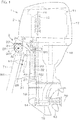
- Fig. 1 is a schematic view showing a left side of an outboard motor 1 according to a first preferred embodiment.
- Fig. 2 is a schematic view showing a suspension device 3 included in the outboard motor 1, viewed from above.
- a contour of an outer surface of the outboard motor main body 2 at a height equal to a height of an upper end of a transom T1 is shown by an alternate long and two short dashed line and an alternate long and short dashed line.
- the alternate long and two short dashed line shows a state in which an outboard motor main body 2 is positioned at an original position between a right maximum steered position and a left maximum steered position.
- the alternate long and short dashed line shows a state in which the outboard motor main body 2 is positioned at the right maximum steered position.
- the outboard motor 1 includes the outboard motor main body 2 that generates thrust to propel a vessel, a suspension device 3 to mount the outboard motor main body 2 to a hull H1, a steering device 4 that turns the outboard motor main body 2 in the right-left direction, and a tilting device 5 that turns the outboard motor main body 2 around the tilt axis At extending horizontally in the right-left direction.
- the outboard motor main body 2 includes an engine 11 as an example of a prime mover that generates power to rotate a propeller 16, and a power transmission device that transmits power of the engine 11 to the propeller 16.
- the outboard motor main body 2 further includes an engine cowl 17 housing the engine 11, and a casing 18 housing the power transmission device. Rotation of the crankshaft 12, which is rotatable around the rotation axis Ac extending in the up-down direction, is transmitted to the propeller 16 via a drive shaft 13, a forward-reverse switching mechanism 14, and the propeller shaft 15 of the power transmission device.
- the suspension device 3 includes a pair of clamp brackets 21 attachable to a transom T1 provided on a rear portion of the hull H1, a swivel bracket 22 supported by the pair of clamp brackets 21 rotatably around the tilt axis At extending in the right-left direction, and a steering shaft 23 supported by the swivel bracket 22 rotatably around the steering axis As extending in the up-down direction.
- the suspension device 3 further includes a top cover 24 disposed above the swivel bracket 22, a pair of end caps 25 respectively disposed on the right and left of the pair of clamp brackets 21, and an upper mount bracket 26 and a lower mount bracket 27 that join the steering shaft 23 to an upper damper mount M1 and a lower damper mount M2 disposed inside the outboard motor main body 2.
- the pair of clamp brackets 21 are respectively disposed on the right and left of the swivel bracket 22.
- An inner side surface 21i of the clamp bracket 21 faces an outer surface 22o of the swivel bracket 22.
- the clamp bracket 21 includes an attaching portion 28 to be attached to the hull H1, and a swivel support 29 that supports the swivel bracket 22.
- the attaching portion 28 is disposed at the rear of the transom T1.
- the swivel support 29 is disposed above the transom T1.
- a bolt b1 that fixes the clamp bracket 21 to the hull H1 is inserted in a bolt attaching hole h1 provided in the attaching portion 28.
- the swivel bracket 22 includes a housing 31 that houses the steering device 4, a tubular shaft support 32 that supports the steering shaft 23 rotatably, and a pair of tubular portions 33 supported by the swivel supports 29 of the clamp brackets 21.
- the pair of tubular portions 33 are respectively disposed on the right and left of the housing 31.
- the tubular portions 33 project laterally from the housing 31.
- the tubular portions 33 extend in the right-left direction.
- the shaft support 32 is positioned more rearward than the tubular portions 33.
- the steering shaft 23 is inserted in the shaft support 32.
- the centerline of the steering shaft 23 is positioned on the steering axis As.
- the upper mount bracket 26 and the lower mount bracket 27 are respectively disposed above and below the shaft support 32.
- the upper mount bracket 26 is joined to the upper damper mount M1 by a bolt, for example, and the lower mount bracket 27 is joined to the lower damper mount M2 by a bolt, for example.
- the upper mount bracket 26 and the lower mount bracket 27 rotate around the steering axis As together with the steering shaft 23.
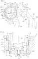
- Fig. 3 is a schematic view of an upper portion of the suspension device 3, viewed from a left side.
- Fig. 4 is a sectional view showing a horizontal section taken along line IV-IV in Fig. 3 .
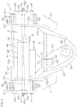
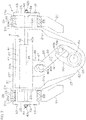
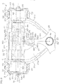
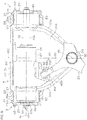
- Fig. 5 and Fig. 6 are partial sectional views of the suspension device 3 from which the top cover 24 has been removed, viewed from above. In Fig. 3 , the end caps 25 and bushings 53, etc., are not shown.
- Fig. 5 shows a state in which a steering tube 44 is positioned at the center
- Fig. 6 shows a state in which the steering tube 44 has moved leftward.
- the housing 31 of the swivel bracket 22 includes a bottom wall 31 b disposed between the pair of clamp brackets 21, a front wall 31f extending upward from a front edge of the bottom wall 31b, and two side walls 31s respectively extending upward from a right edge and a left edge of the bottom wall 31 b.
- the top cover 24 is joined to the housing 31 by bolts b2, for example.
- the top cover 24 and the housing 31 define a housing chamber that houses the steering device 4.
- a steering actuator 41 of the steering device 4 is disposed at a position above the bottom wall 31 b and behind the front wall 31f.
- the swivel support 29 of the clamp bracket 21 is positioned laterally of the housing 31 of the swivel bracket 22.
- a tubular portion 33 of the swivel bracket 22 is inserted in the swivel support 29.
- the tubular portion 33 is supported by the swivel support 29 via a plurality of bushings 53 disposed between the tubular portion 33 and the swivel support 29.
- the tubular portion 33 penetrates through the swivel support 29 in the right-left direction.
- the end cap 25 is fixed to the tubular portion 33 by a plurality of bolts b3, for example.
- a steering rod 42 of the steering actuator 41 provided in the steering device 4 is supported by two end caps 25 via a plurality of shaft dampers 54.
- the steering device 4 includes an electric steering actuator 41 that converts electric power into linear motion in the right-left direction and a motion converter 46 that converts the linear motion generated from the steering actuator 41 into rotation of the steering shaft 23.
- the steering actuator 41 includes the steering rod 42 that extends in the right-left direction and the steering tube 44 that reciprocates in the right-left direction along the steering rod 42.
- the steering rod 42 is an example of a support shaft.
- the steering tube 44 and the steering rod 42 extend in the right-left direction along the tilt axis At.
- the steering rod 42 penetrates the steering tube 44 in the right-left direction. Both end portions of the steering rod 42 protrude from both end portions of the steering tube 44, respectively.
- the both end portions of the steering rod 42 are supported by the swivel bracket 22 via two end caps 25.
- the steering tube 44 includes an inner tube 69 that surrounds the steering rod 42 and an electric motor 62 that rotates the inner tube 69.
- the steering tube 44 further includes reduction gears 63 that move the inner tube 69 and the steering rod 42 relatively in an axial direction of the steering rod 42 in accordance with the rotation of the inner tube 69 or the steering rod 42 and a tubular housing 67 that houses the inner tube 69, the electric motor 62, and the reduction gears 63.
- the electric motor 62 includes a rotor 62b that surrounds the inner tube 69 and a stator 62a that surrounds the rotor 62b.
- the stator 62a is connected to a battery via a wiring 45.
- the stator 62a is surrounded by the housing 67.
- the stator 62a is held by the housing 67.
- the rotor 62b is held by the inner tube 69.
- the rotor 62b rotates together with the inner tube 69 around a centerline of the steering rod 42.
- the reduction gears 63 are an example of at least one reduction gear that convert the rotation of the electric motor 62 into the linear motion of the steering tube 44 in the right-left direction.
- the reduction gears 63 may be a ball screw mechanism, for example.
- the reduction gears 63 include a ball screw 64 that extends in the right-left direction along the tilt axis At, a ball nut 66 that surrounds the ball screw 64, and a plurality of balls 65 that are disposed between the ball screw 64 and the ball nut 66.
- the ball screw 64 is provided in the steering rod 42, and the ball nut 66 is provided in the inner tube 69.
- the ball screw 64 may be integral and unitary with the steering rod 42, or may be a member that is separate from the steering rod 42 and fixed to the steering rod 42.
- the ball nut 66 may be integral and unitary with the inner tube 69, or may be a member that is separate from the inner tube 69 and fixed to the inner tube 69.
- the housing 67 surrounds the inner tube 69.
- the housing 67 is longer than the inner tube 69 in the right-left direction.
- the housing 67 holds the ball nut 66 via a plurality of bearings B1.
- An outer diameter of the tubular housing 67 is smaller than an inner diameter of the tubular portion 33 of the swivel bracket 22.
- the housing 67 is movable to a plurality positions including a position above the housing 31 and a position in a space surrounded by the tubular portion 33 of the swivel bracket 22.
- the rotor 62b and the ball nut 66 move in an axial direction of the ball screw 64 with respect to the ball screw 64 while rotating with respect to the ball screw 64.
- the housing 67 moves in the axial direction of the ball screw 64 with respect to the ball screw 64.
- the linear motion of the housing 67 in the right-left direction is converted into rotation of the steering shaft 23 by the motion converter 46.
- the outboard motor main body 2 rotates around the steering axis As.
- the motion converter 46 includes a drive member 47 that moves in an axial direction of the steering actuator 41 corresponding to the right-left direction, a driven member 50 that rotates around the steering axis As, and a columnar pin 48 and a slide groove 49 that convert linear motion of the drive member 47 into rotation of the driven member 50.
- Fig. 5 shows an example in which the columnar pin 48 is fixed to the drive member 47, and the slide groove 49 in which the columnar pin 48 is fitted is provided on the driven member 50.
- the driven member 50 is an example of a steering arm that rotates together with the steering shaft 23 around the steering axis As.
- the drive member 47 is disposed at the rear of the steering tube 44.
- the drive member 47 extends rearward from the steering tube 44.
- a front end portion of the drive member 47 is fixed to a housing 67 of the steering tube 44.
- the drive member 47 moves together with the housing 67 in the axial direction of the ball screw 64.
- a rear end portion of the drive member 47, corresponding to a tip end portion, is disposed above a front end portion of the driven member 50.
- the columnar pin 48 extends downward from the rear end portion of the drive member 47.
- the drive member 47 is shorter in the up-down direction than the steering tube 44, and shorter in the right-left direction than the steering tube 44.
- the driven member 50 extends forward from the steering shaft 23.
- the driven member 50 is fixed to the steering shaft 23.
- a front end portion of the driven member 50 corresponding to a tip end portion, is disposed at a position more forward than the steering shaft 23 and more rearward than the steering tube 44.
- the front end portion of the driven member 50 is positioned above the bottom wall 31b of the swivel bracket 22.
- the slide groove 49 is provided at the front end portion of the driven member 50.
- the slide groove 49 may have a U-shape extending in a radial direction (direction perpendicular to the steering axis As) in a plan view or an O-shape elongated in the radial direction in a plan view.
- the drive member 47 is supported by a guide shaft 51 extending in the right-left direction.
- the guide shaft 51 is inserted in a guide hole h2 penetrating through the drive member 47.
- the guide shaft 51 is a parallel guide that is parallel to the steering rod 42.
- the drive member 47 is guided by the guide shaft 51 in the axial direction of the guide shaft 51.
- the guide shaft 51 is supported on side walls 31s of the swivel bracket 22 via two guide dampers 52.
- the two guide dampers 52 are respectively attached to both end portions of the guide shaft 51.
- the guide dampers 52 are preferably made of an elastic material such as rubber or resin.
- the guide damper 52 includes a cylindrical portion surrounding an outer circumferential surface of the guide shaft 51 and a bottom portion facing an end surface of the guide shaft 51.
- the first end portion (the right end portion in Fig. 5 ) of the guide shaft 51 is inserted in a blind hole h3 opening at an inner side surface of the side wall 31s.
- the first end portion of the guide shaft 51 is supported by a bottom surface of the blind hole h3 via the guide damper 52.
- the second end portion (left end portion in Fig. 5 ) of the guide shaft 51 is inserted in a through hole h4 penetrating through the side wall 31s.
- a plug P1 is screwed in the through hole h4.
- the second end portion of the guide shaft 51 is supported by the plug P1 via the guide damper 52. Accordingly, the guide shaft 51 is held by the swivel bracket 22.
- the centerline of the steering tube 44 and the steering rod 42 of the steering actuator 41 is positioned on the tilt axis At.
- the inner circumferential surface of the tubular portion 33 surrounds the steering tube 44 in a side view.
- the inner diameter of the tubular portion 33 is larger than the outer diameter of the steering tube 44.
- the difference between the inner diameter of the tubular portion 33 and the outer diameter of the steering tube 44 is smaller than the outer diameter of the steering shaft 23.
- the swivel support 29 of the clamp bracket 21 includes an inner circumferential surface 29a surrounding the tubular portion 33.
- the inner circumferential surface 29a opens at both of the inner side surface 21i and the outer surface 21o of the clamp bracket 21.
- the steering actuator 41, the tubular portion 33, and the inner circumferential surface 29a are preferably coaxial with each other.
- the bushings 53 are preferably made of a material such as a resin or a metal that is softer than the clamp brackets 21 and the swivel bracket 22.
- the bushing 53 includes a cylindrical portion 53a disposed between the inner circumferential surface 29a and the tubular portion 33, and an annular flange 53b extending outward from an end portion of the cylindrical portion 53a.
- the flange 53b of one bushing 53 is disposed between the inner side surface 21 i of the clamp bracket 21 and the outer surface 22o of the swivel bracket 22.
- the flange 53b of the other bushing 53 is disposed between the outer surface 21o of the clamp bracket 21 and the inner side surface of the end cap 25.
- the tubular portion 33 of the swivel bracket 22 includes a toric portion 33a surrounding the steering tube 33 of the steering actuator 41 in a side view, and a plurality of projections 33b projecting inward from the inner circumferential surface of the toric portion 33a.
- the shafts of the plurality of bolts b3 (refer to Fig. 4 ) that fix the end cap 25 to the swivel bracket 22 are attached to a plurality of female screw holes h5 provided in the tubular portion 33.
- the plurality of female screw holes h5 open at an end surface of the tubular portion 33.
- the plurality of female screw holes h5 are arranged in the circumferential direction.
- the plurality of projections 33b are disposed at positions corresponding to the plurality of female screw holes h5. As shown in Fig. 4 , the projections 33b are shorter in the right-left direction than the toric portion 33a.
- the end cap 25 preferably has a discoid shape coaxial with the tubular portion 33.
- the outer diameter of the end cap 25 is larger than the diameter of the inner circumferential surface 29a of the clamp bracket 21.
- the opening of the tubular portion 33 is covered by the end cap 25 from a lateral side.
- An outer circumferential portion of the end cap 25 is disposed more outward than the outer circumferential surface of the tubular portion 33.
- the shafts of the bolts b3 are inserted from the outside in the through holes h6 penetrating through the end cap 25 in the right-left direction, and project inward from the end cap 25. Tip end portions of the shafts of the bolts b3 are screwed into female screw holes h5 provided in the tubular portion 33.
- the heads of the bolts b3 are disposed outside the end cap 25.
- An end portion of the steering rod 42 of the steering actuator 41 is supported by the end cap 25 via two shaft dampers 54.
- the end portion of the steering rod 42 is inserted in a through hole h7 penetrating through a central portion of the end cap 25 in the thickness direction.
- the steering rod 42 includes a large diameter portion 42a, a small diameter portion 42b, and a male screw portion 42c.
- the small diameter portion 42b of the steering rod 42 penetrates through the end cap 25 in the right-left direction.
- the male screw portion 42c of the steering rod 42 is disposed outside the end cap 25.
- a fixing nut N1 for example, is screwed onto the male screw portion 42c of the steering rod 42.
- the shaft damper 54 is preferably made of an elastic material such as rubber or resin.
- the shaft damper 54 includes a cylindrical portion 54a disposed between the outer circumferential surface of the steering rod 42 and the inner circumferential surface of the end cap 25, and an annular flange 54b extending outward from an end portion of the cylindrical portion 54a. End surfaces of the cylindrical portions 54a of the two shaft dampers 54 face each other inside the through hole h7 of the end cap 25.
- the end cap 25 is disposed between the two flanges 54b.
- the two shaft dampers 54 are sandwiched by two washers W1 in the axial direction.
- Fig. 6 shows a state in which a portion of the steering tube 44 is located inside a space surrounded by both of the tubular portion 33 of the swivel bracket 22 and the inner circumferential surface 29a of the clamp bracket 21.
- the drive member 47 moves in the axial direction of the steering actuator 41 together with the steering tube 44. Along with this, an inner side surface of the driven member 50 defining the slide groove 49 is pushed in the right-left direction by the columnar pin 48. At this time, the driven member 50 pivots around the steering axis As while the columnar pin 48 moves in a radial direction inside the slide groove 49 with respect to the driven member 50. Accordingly, the steering shaft 23 rotates around the steering axis As, and along with this, the outboard motor main body 2 rotates around the steering axis As.
- the outboard motor main body 2 that rotates the propeller 16 rotates around the steering axis As together with the steering shaft 23 in accordance with movement of the steering tube 44 as an example of a movable body.
- the steering tube 44 is surrounded by the inner circumferential surface 29a of the clamp bracket 21 in a side view. Therefore, a space in which the steering tube 44 is disposed does not need to be provided between the clamp bracket 21 and the cowl 17. Further, since the steering tube 44 is movable to the inside of the inner circumferential surface 29a of the clamp brackets 21, the clamp brackets 21 do not need to be disposed laterally of the moving range of the steering tube 44. Therefore, the pair of clamp brackets 21 are prevented from increasing in size in the right-left direction.
- the outboard motor main body 2 rotates in the right-left direction around the steering axis As, the outboard motor main body 2 approaches the right or left clamp bracket 21 (refer to the outboard motor main body 2 shown by the alternate long and short dashed line in Fig. 2 ). If the width between the pair of clamp brackets 21 in the right-left direction is large, the outboard motor main body 2 may come into contact with the clamp bracket 21. Therefore, in order to prevent this, the clamp brackets 21 need to be shortened in the front-rear direction or reduced in size in the right-left direction. In the present preferred embodiment, since the width between the pair of clamp brackets 21 is reduced, such measures do not need to be taken.
- the steering tube 44 overlaps the tilt axis At in a side view.
- the steering tube 44 also rotates around the tilt axis At.
- the range through which the steering tube 44 passes is smaller as compared with the case in which the steering tube 44 does not overlap the tilt axis. Therefore, a space inside the hull H1 in which a portion of the outboard motor main body 2 is disposed when the outboard motor main body 2 is tilted up is reduced. Accordingly, the space inside the hull H1 is effectively utilized.
- the steering rod 42 as an example of a support shaft penetrates through the clamp brackets 21.
- the steering tube 44 moves in the axial direction of the steering rod 42 along the steering rod 42. If the steering rod 42 is long, the range in which the steering tube 44 is movable is enlarged. If the range in which the steering tube 44 is movable is large, the steering angle of the outboard motor main body 2 (rotation angle around the steering axis As) is increased.
- the steering rod 42 extends to penetrate through the clamp brackets 21. Therefore, the range in which the steering tube 44 is movable is enlarged, and the steering angle of the outboard motor main body 2 is increased.
- an impact applied to the steering rod 42 is absorbed by the shaft dampers 54. Therefore, the strength required for the steering rod 42 is reduced, so that the steering rod 42 is able to be reduced in size. Further, since an impact applied to the steering tube 44 is also absorbed via the steering rod 42, the steering tube 44 is able to be reduced in size. Thus, the steering tube 44 and the steering rod 42 are downsized, so that the width between the pair of clamp brackets 21 is further reduced.
- the tubular portion 33 corresponding to a tilting shaft is provided on the swivel bracket 22.
- the swivel bracket 22 is rotatable around the tubular portion 33 with respect to the clamp bracket 21.
- the steering tube 44 is movable to the inside of the tubular portion 33.
- a tilting shaft to be inserted in the clamp bracket 21 defines, inside the clamp bracket 21, a space in which the steering tube 44 is disposed. Accordingly, while a moving range of the steering tube 44 is maintained, the width between the pair of clamp brackets 21 is reduced.
- the driven member 50 pivots around the steering axis As.
- a pivoting angle of the driven member 50 rotation angle around the steering axis As
- the longer the distance D1 (refer to Fig. 5 ) from the steering axis As to the tip end of the driven member 50, the larger the pivoting range of the driven member 50 (the range through which the driven member 50 passes). If the pivoting range of the driven member 50 is large, the width between the pair of clamp brackets 21 may need to be increased.
- the steering tube 44 is located closer to the driven member 50, the distance to the tip end of the driven member 50 is shortened. However, if the steering tube 44 is located closer to the driven member 50, the cowl 17 may need to be downsized, or the outboard motor main body 2 may need to be moved upward.
- a portion of the drive member 47 is positioned between the steering tube 44 and the driven member 50. Therefore, without locating the steering tube 44 closer to the driven member 50, movement of the steering tube 44 is transmitted to the driven member 50. Accordingly, without changing the size of the cowl 17 and the position of the outboard motor main body 2, the pivoting range of the driven member 50 is narrowed. Therefore, the width between the pair of clamp brackets 21 is narrowed.
- the drive member 47 is shorter in the up-down direction and the right-left direction than the steering tube 44. A portion of the drive member 47 is positioned between the steering tube 44 and the driven member 50. If the drive member 47 is long in the up-down direction, the size of the cowl 17 or the position of the outboard motor main body 2 may need to be changed. However, since the drive member 47 is shorter in the up-down direction than the steering tube 44, so that without changing the size of the cowl 17 and the position of the outboard motor main body 2, a portion of the drive member 47 is disposed between the steering tube 44 and the driven member 50.
- the drive member 47 is shorter in the right-left direction than the steering tube 44, although the moving distance of the drive member 47 in the movement direction is the same as that of the steering tube 44, the movement range of the drive member 47 (range through which the drive member 47 passes) is smaller than that of the steering tube 44. Therefore, the width between the pair of clamp brackets 21 is further narrowed.
- the drive member 47 is supported by the guide shaft 51, so that the drive member 47 is moved in a stable manner in the movement direction. Further, the drive member 47 is supported by both of the steering tube 44 and the guide shaft 51, so that warping of the drive member 47 is significantly reduced or prevented.
- an impact applied to the guide shaft 51 is absorbed by the guide dampers 52. Therefore, the strength required for the guide shaft 51 is reduced, so that the guide shaft 51 is able to be reduced in size. Thus, since the guide shaft 51 is downsized, the width between the pair of clamp brackets 21 is further reduced.
- the motion converter 46 may further include a rotation arm 55 rotatable around a rotation axis Ar parallel to or substantially parallel to the steering axis As.
- the rotation arm 55 is supported by the swivel bracket 22 via a central shaft 56 extending in the up-down direction.
- the rotation arm 55 is rotatable around the rotation axis Ar corresponding to a centerline of the central shaft 56.
- the rotation arm 55 is disposed above the bottom wall 31b of the swivel bracket 22.
- the rotation arm 5 is disposed lower than the drive member 47 and the driven member 50.
- the drive member 47 is joined to the rotation arm 55 by a columnar pin 48a extending upward from the rotation arm 55 and a slide groove 49a provided on the drive member 47.
- the driven member 50 is joined to the rotation arm 55 by a columnar pin 48b extending upward from the rotation arm 55 and a slide groove 49b provided on the driven member 50.
- Fig. 8 and Fig. 9 are partial sectional views of the suspension device 3, from which the top cover 24 (refer to Fig. 1 ) is removed, and the steering device 4, viewed from above.
- Fig. 8 shows a position of the steering tube 44 when the outboard motor main body 2 (refer to Fig. 1 ) is disposed at the original position.
- Fig. 9 shows a position of the steering tube 44 when the outboard motor main body 2 is disposed at the right maximum steered position.
- a reference plane WO shown in Fig. 8 and Fig. 9 denotes the vertical plane that passes through the steering axis As and perpendicular or substantially perpendicular to the right-left direction.
- components equivalent to the above described components shown in Fig. 1 to Fig. 7 are designated by the same reference characters as in FIG. 1 , etc., and description thereof is omitted.
- the steering actuator 41 includes reduction gears 70, instead of the reduction gears 63 according to the first preferred embodiment.
- the reduction gears 70 may be a roller screw assembly, for example.
- the roller screw assembly includes a center shaft 71 extending in the right-left direction and a plurality of cylindrical rollers 72 disposed around the center shaft 71.
- the inner tube 69 surrounds the plurality of cylindrical rollers 72.
- a centerline of the center shaft 71 is disposed on the tilt axis At.
- the center shaft 71 may be integral and unitary with the steering rod 42, or may be a member that is separate from the steering rod 42 and fixed to the steering rod 42.
- Each of the spiral screw threads provided on the outer circumferential surfaces of the cylindrical rollers 72 is engaged with a spiral screw thread provided on the outer circumferential surface of the center shaft 71 and a spiral screw thread provided on the inner circumferential surface of the inner tube 69.
- the rotation of the center shaft 71 is converted into the linear motion of the inner tube 69 by the center shaft 71, the cylindrical roller 72, and the inner tube 69.
- the rotation of the inner tube 69 is converted into the linear motion of the center shaft 71 by the center shaft 71, the cylindrical roller 72, and the inner tube 69.
- the torque transmitted from the electric motor 62 to the inner tube 69 is converted into a driving force to move the inner tube 69 linearly in the right-left direction by the center shaft 71, the cylindrical roller 72, and the inner tube 69.
- This driving force moves the steering tube 44 in a right direction or a left direction with respect to the steering rod 42.
- the moving distance and the movement direction of the steering tube 44 are controlled by the rotation angle and the rotation direction of the electric motor 62.
- the steering device 4 includes a motion converter 81 that converts the linear motion of the steering actuator 41 into the rotation of the steering shaft 23, instead of the motion converter 46 according to the first preferred embodiment.
- the motion converter 81 includes a spherical bushing 82 attached to the front end portion of the driven member 50 and a bushing holder 83 that holds the bushing 82.
- the bushing holder 83 moves in the right-left direction with respect to the steering rod 42 together with the steering tube 44.
- the front end portion of the driven member 50 is inserted into an arm-insertion hole 83h extending forward from the rear surface of the bushing holder 83. Further, the front end portion of the driven member 50 is inserted into an insertion hole 82h extending forward from the spherical outer surface 82o of the bushing 82.
- the driven member 50 is an example of the steering arm.
- the steering actuator 41 when, the steering actuator 41 generates a left steering force that moves the steering tube 44 in the right direction, this left steering force is transmitted to the driven member 50 via the housing 67, the bushing holder 83, and the bushing 82.
- the driven member 50 is pushed rightward, and the driven member 50 and the steering shaft 23 turn rightward around the steering axis As.
- the outboard motor main body 2 turns leftward around the steering axis As accordingly.
- Fig. 9 shows the position of the steering tube 44 when the outboard motor main body 2 is disposed at the right maximum steered position.
- the left end portion of the steering tube 44 is disposed inside a space surrounded by both of the swivel support 2 of the left clamp bracket 21 and the left tubular portion 33 of the swivel bracket 22.
- the left maximum steered position is a position symmetrical or substantially symmetrical to the right maximum steered position with respect to the reference plane WO.
- the right end portion of the steering tube 44 is disposed inside a space surrounded by both of the swivel support 2 of the right clamp bracket 21 and the right tubular portion 33 of the swivel bracket 22.
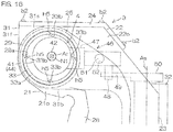
- Fig. 10 is a left side view of the upper portion of the suspension device 3 from which a side cover 93 (refer to Fig. 12 ) is removed.
- Fig. 11 is a left side view of a handle 92 into which the steering rod 42 is inserted.
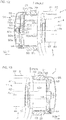
- Fig. 12 is a partial sectional view of the left end portion of the suspension device 3, viewed from above.
- Fig. 13 is a partial sectional view of the right end portion of the suspension device 3, viewed from above.
- Fig. 14 is a partial sectional view for describing procedures to manually steer the outboard motor main body 2 (refer to Fig. 1 ).
- components equivalent to the above described components shown in Fig. 1 to Fig. 9 are designated by the same reference characters as in FIG. 1 , etc., and description thereof is omitted.
- the outboard motor 1 may include a manual steering device 91 that turns rightward or leftward the outboard motor main body 2, in addition to the automatic steering device 4.
- the manual steering device 91 includes the handle 92 that is to be operated by an operator when the outboard motor main body 2 is steered manually and a handle attachment 42d to which the handle 92 is attached.
- the handle attachment 42d is provided in the steering rod 42 and the handle 92 is attached to the steering rod 42.
- the suspension device 3 may further include the side cover 93 attached to the end cap 25.
- the side cover 93 is disposed laterally of the end cap 25 and fixed to the end cap 25 by bolts b4, for example.
- the handle 92 is disposed between the side cover 93 on the left side and the end cap 25 on the left side, and covered by the side cover 93.
- the handle 92 includes at least one contact portion 92a that contacts with a hand of the operator and a connector 92b that connects the at least one contact portion 92a with the handle attachment 42d.
- Fig. 11 shows an example in which two contact portions 92a are provided on the handle 92.
- the handle 92 may include a folded metal plate, for example.
- the contact portion 92a is disposed around the large diameter portion 42a of the steering rod 42 in a side view.
- the handle attachment 42d includes a shaft inserted into a through hole 92h that penetrates the connector 92b of the handle 92 in the right-left direction.
- the handle attachment 42d is provided on the outer circumferential surface of the small diameter portion 42b of the steering rod 42.
- Fig. 11 shows an example in which the through hole 92h of the handle 92 has a quadrilateral shape and the handle attachment 42d includes two flat surfaces 42s parallel to each other.
- Each of the handle attachment 42d and the through hole 92h may have any shape as long as the shape is able to transmit torque from the handle 92 to the steering rod 42.
- the handle attachment 42d may be a spline shaft and the through hole 92h may be a spline hole.
- the handle 92 may be fixed to the handle attachment 42d by welding or caulking, for example.
- the left end portion of the steering rod 42 includes the small diameter portion 42b and the male screw portion 42c.
- the small diameter portion 42b of the steering rod 42 is inserted into the through hole h7 that penetrates the central portion of the left end cap 25 in the right-left direction.
- the inner diameter of the through hole h7 is smaller than the outer diameter of the large diameter portion 42a of the steering rod 42.
- the male screw portion 42c of the steering rod 42 is disposed laterally of the end cap 25.
- the fixing nut N1 is screwed onto the male screw portion 42c.
- the connector 92b of the handle 92 is disposed between the fixing nut N1 and the end cap 25.
- the handle 92 and the end cap 25 are sandwiched by the inner side surface N1x of the fixing nut N1 and the end surface 42x of the large diameter portion 42a in the axial direction of the steering rod 42.
- the steering rod 42 and the handle 92 are fixed to the end cap 25.
- the end cap 25 is fixed to the swivel bracket 22 by the bolts b3, for example.
- the steering rod 42 and the handle 92 are fixed to the swivel bracket 22 indirectly.
- the small diameter portion 42b and the male screw portion 42c are not provided in the right end portion of the steering rod 42.
- the right end portion of the large diameter portion 42a of the steering rod 42 which corresponds to the right end portion of the steering rod 42, is inserted into a through hole h8 that penetrates the central portion of the right end cap 25 in the right-left direction.
- the inner diameter of the through hole h8 is larger than the outer diameter of the large diameter portion 42a of the steering rod 42.
- the steering rod 42 is supported by the inner circumferential surface of the right end cap 25, and is not fixed to the right end cap 25.
- the handle 92 is rotated by hand.
- the handle 92 and the steering rod 42 rotate around the centerline of the steering rod 42 corresponding to the tilt axis At.
- the rotation of the steering rod 42 is converted into the movement of the steering tube 44 in the right-left direction by the reduction gears 63 shown in Fig. 5 .
- the outboard motor main body 2 turns rightward or leftward around the steering axis As, and is steered manually.
- the steering rod 42 is prevented from rotating with respect to the swivel bracket 22 by the fixing nut N1 attached to the steering rod 42.
- the electric motor 62 rotates the inner tube 69 (refer to 5)
- the rotation of the inner tube 69 is converted into the relative motion of the inner tube 69 and the steering rod 42 in the axial direction of the steering rod 42 by the reduction gears 63.
- the steering tube 44 which is an example of the movable body, moves in the right-left direction and the outboard motor main body 2 is steered automatically.
- the steering rod 42 When the fixing nut N1 is loosened, the steering rod 42 is able to be rotated with respect to the swivel bracket 22. In this state, when the operator operates the handle 92 attached to the handle attachment 42d of the steering rod 42 so as to rotate the steering rod 42, the rotation of the steering rod 42 is converted into the relative motion of the inner tube 69 and the steering rod 42 in the axial direction of the steering rod 42 by the reduction gears 63. Thus, the steering tube 44 moves in the right-left direction and the outboard motor main body 2 is steered manually.
- the operator directly pushes the outboard motor main body 2 so as to manually steer the outboard motor main body 2.
- the reduction ratio of the reduction gears 63 is large, even when a circuit to drive the electric motor 62 is opened, the outboard motor main body 2 is not steered manually unless a large force is applied to the outboard motor main body 2.
- the outboard motor main body 2 is steered manually with a small force as compared with a case in which the outboard motor main body 2 is pushed directly.
- the handle 92 which is to be operated when the outboard motor main body 2 is steered manually, is provided in the outboard motor 1 and attached to the handle attachment 42d.
- the user of the outboard motor 1 does not need to prepare a tool, etc., and to attach the tool, etc., to the handle attachment 42d.
- the time required to prepare the manual steering of the outboard motor main body 2 is shortened accordingly.
- the steering rod 42 is prevented from rotating with respect to the swivel bracket 22 only by the single fixing nut N1.
- the prevention of the rotation of the steering rod 42 with respect to the swivel bracket 22 is not released unless all of the fixing nuts N1 are loosened.
- the prevention of the rotation of the steering rod 42 with respect to the swivel bracket 22 is released only by loosening the single fixing nut N1.
- the steering rod 42 of the steering actuator 41 is parallel to the tilt axis At.
- the steering rod 42 of the steering actuator 41 may be inclined with respect to the tilt axis At.
- the inner circumferential surface 29a of the clamp bracket 21 opens at both of the inner side surface 21i and the outer surface 21o of the clamp bracket 21 is described.
- the inner circumferential surface 29a does not need to open at the outer surface 21o of the clamp bracket 21. That is, the insertion hole defined by the inner circumferential surface 29a may not be a through hole but be a blind hole.
- the steering rod 42 of the steering actuator 41 may be directly supported by the end caps 25. That is, the shaft dampers 54 disposed between the steering rod 42 and the end caps 25 may be omitted. Similarly, the guide dampers 52 disposed between the guide shaft 51 and the swivel bracket 22 may be omitted. In addition, the guide shaft 51 that guides the drive member 47 in the axial direction of the steering actuator 41 may be omitted.
- the tubular portions 33 to be inserted into the inner circumferential surface 29a of the clamp brackets 21 may be members separate from the housing 31 of the swivel bracket 22.
- any of press fitting, welding, and fastening with bolts may be used, or a method other than these may be used.
- the right end portion of the steering rod 42 may be fixed to the end cap 25 on the right side by the fixing nut N1.
- the handle attachment 42d may include a hole that is recessed from the left end surface of the steering rod 42 and has a polygonal shape in a side view.
- Fig. 15 shows an example in which the hole has a hexagonal shape in a side view and is provided in the left end surface of the steering rod 42.
- an end portion of a hexagonal wrench 94 which is an example of the handle, is inserted into the hole and the hexagonal wrench 94 is rotated.
- the outboard motor 1 may not include the handle 92.
- a dedicated or general-purpose tool which is an example of the handle, may be attached to the handle attachment 42d, when needed.
- the handle 92 and an additional nut may be attached to the male screw portion 42c of the steering rod 42 so as to cause the two nuts (the fixing nut N1 and the additional nut) to sandwich the handle 92 in the axial direction of the steering rod 42 and to fix the handle 92 to the steering rod 42. That is, the male screw portion 42c of the steering rod 42 may double as the handle attachment 42d.
- the steering actuator 41 may be eccentric with respect to the tilt axis At. That is, the centerlines of the steering tube 44 and the steering rod 42 do not need to be disposed on the tilt axis At. In this case, the steering actuator 41 does not need to overlap the tilt axis At in a side view.
Landscapes
- Chemical & Material Sciences (AREA)
- Engineering & Computer Science (AREA)
- Combustion & Propulsion (AREA)
- Mechanical Engineering (AREA)
- Ocean & Marine Engineering (AREA)
- Power Steering Mechanism (AREA)
Abstract
Description
- The present invention relates to an outboard motor that propels a vessel.
-
US 7,311,571 B1 discloses a marine propulsion system including an outboard motor. The marine propulsion system includes a transom bracket to be attached to a transom, a swivel bracket supported by the transom bracket rotatably around a tilt axis, and a steering cylinder that rotates the outboard motor around a steering axis. - The steering cylinder is disposed at a position above the transom bracket and below a cowl of the outboard motor in a side view. The steering cylinder is integral and unitary with the swivel bracket. The steering cylinder houses a piston member. When the piston member moves along a centerline of the steering cylinder inside the steering cylinder, a swivel tube is driven around the steering axis.
- In a conventional marine propulsion system, a hydraulic cylinder for steering is disposed in front of the swivel bracket. When the outboard motor is tilted up, the hydraulic cylinder moves to the front side of the transom, so that a space within which the hydraulic cylinder is disposed must be secured inside a vessel. In the marine propulsion system disclosed in
US 7,311,571 B1 , to avoid this, the steering cylinder is disposed above the transom bracket. - However, in the marine propulsion system disclosed in
US 7,311,571 B1 , a space within which the steering cylinder is disposed must be secured between the transom bracket and the cowl of the outboard motor, so that the cowl needs to be downsized or the entire outboard motor needs to be moved upward. If the cowl is downsized, the layout of devices such as an internal combustion to be disposed inside the cowl is further limited. If the entire outboard motor is moved upward, a portion of the outboard motor which enters the inside of the hull when the outboard motor is tilted up becomes larger. Therefore, a larger space needs to be secured inside the hull.
In order to overcome the previously unrecognized and unsolved challenges described above. It is an object of the present invention to provide outboard motors that are able to provide and position rearward movable bodies that steer outboard motor main bodies without influencing sizes of cowls and positions of the outboard motor main bodies. According to the present invention said object is solved by an outboard motor according toClaim 1. Preferred embodiments are laid down in the dependent claims. - A preferred embodiment provides an outboard motor including a pair of clamp brackets each provided with an inner side surface, an inner circumferential surface that is open at the inner side surface, and an attaching portion attachable to a rear surface of a hull, and spaced apart from each other in the right-left direction; a swivel bracket disposed between the pair of clamp brackets, and rotatable with respect to the pair of clamp brackets around a tilt axis extending in the right-left direction; a movable body at least a portion of which is surrounded by the inner circumferential surface of the clamp bracket in a side view of the outboard motor and movable to a plurality of positions including a position above the swivel bracket and a position inside a space surrounded by the inner circumferential surface of the clamp bracket; a steering shaft that rotates around a steering axis extending in the up-down direction in accordance with movement of the movable body; and an outboard motor main body that rotates around the steering axis together with the steering shaft and includes a prime mover that generates power to rotate a propeller.
- With the above structural arrangement, the outboard motor main body, which rotates a propeller, rotates around the steering axis together with the steering shaft in accordance with movement of the movable body. At least a portion of the movable body is surrounded by the inner circumferential surface of the clamp bracket in a side view. Therefore, a space within which the movable body is disposed does not need to be provided between the clamp brackets and the cowl. Further, the movable body is movable to the inside of the inner circumferential surface of the clamp bracket, so that the clamp brackets do not need to be disposed laterally of a moving range of the movable body. Therefore, the pair of clamp brackets are prevented from increasing in size in the right-left direction.
- When the outboard motor main body rotates in the right-left direction around the steering axis, the outboard motor main body approaches the right or left clamp bracket. If the width between the pair of clamp brackets in the right-left direction is large, the outboard motor main body may come into contact with the clamp bracket. Therefore, in order to prevent this, the clamp brackets need to be shortened in the front-rear direction or reduced in size in the right-left direction. With the above-described structural arrangement, the width between the pair of clamp brackets is reduced, so that the above measures are unnecessary.
- According to a preferred embodiment, the movable body may overlap the tilt axis in a side view of the outboard motor.
- When the outboard motor main body rotates around the tilt axis, the movable body also rotates around the tilt axis. When the movable body overlaps the tilt axis in a side view, the range through which the movable body passes is smaller than in the case in which the movable body does not overlap the tilt axis. Therefore, a space inside a vessel in which a portion of the outboard motor main body is disposed when the outboard motor main body is tilted up is reduced. Accordingly, the space inside the vessel is effectively utilized.
- According to a preferred embodiment, the outboard motor may further include a support shaft extending in an axial direction parallel to or substantially parallel to the tilt axis. The movable body may be movable in an axial direction of the support shaft along the support shaft along the support shaft.
- According to a preferred embodiment, the support shaft may penetrate through the clamp bracket.
- The movable body moves in the axial direction of the support shaft along the support shaft. If the support shaft is long, the moving range of the movable body is enlarged. If the moving range of the movable body is large, a steering angle of the outboard motor main body (rotation angle around the steering axis) is increased. With the above structural arrangement, the support shaft is elongated so as to penetrate through the clamp bracket. Therefore, the moving range of the movable body is enlarged, and the steering angle of the outboard motor main body is increased.
- According to a preferred embodiment, the outboard motor may further include a shaft damper that supports the support shaft.
- With the above structural arrangement, an impact applied to the support shaft is absorbed by the shaft damper. Therefore, the strength required for the support shaft is reduced, so that the support shaft is able to be reduced in size. Further, an impact applied to the movable body via the support shaft is also absorbed, so that the movable body is able to be reduced in size. Thus, since the movable body and the support shaft are downsized, the width between the pair of clamp brackets is further reduced.
- According to a preferred embodiment, the swivel bracket may include a tubular portion surrounding the tilt axis and is inserted in the inner circumferential surface of the clamp bracket. The movable body may be movable to a position inside a space surrounded by both of the inner circumferential surface of the clamp bracket and the tubular portion.
- With the above structural arrangement, the tubular portion corresponding to a tilting shaft is provided on the swivel bracket. The swivel bracket is rotatable around the tubular portion with respect to the clamp brackets. The movable body is movable to the inside of the tubular portion. In other words, the tilting shaft to be inserted in the clamp bracket defines a space inside which the movable body is disposed inside the clamp bracket. Accordingly, the width between the pair of clamp brackets is reduced while the moving range of the movable body is maintained.
- According to a preferred embodiment, the outboard motor may further indude a motion converter including a driven member that rotates around the steering axis together with the steering shaft and a drive member disposed closer to the driven member than the movable body and moves in a movement direction of the movable body together with the movable body, and that converts movement of the movable body into rotation of the steering shaft.
- With the above structural arrangement, when the movable body and the drive member move in a movement direction of the movable body, the driven member pivots around the steering axis. When the pivoting angle of the driven member (rotation angle around the steering axis) is the same, the larger the distance from the steering axis to the tip end of the driven member, the larger the pivoting range of the driven member (range through which the driven member passes). If the pivoting range of the driven member is large, the width between the pair of clamp brackets may have to be increased.
- For example, if the movable body is located closer to the driven member, the distance to the tip end of the driven member is shortened. However, if the movable body is located closer to the driven member, the cowl may need to be downsized or the outboard motor main body may need to be moved upward.
- With the above structural arrangement, a portion of the drive member is positioned between the movable body and the driven member. Therefore, without locating the movable body closer to the driven member, the movement of the movable body is transmitted to the driven member. Accordingly, the pivoting range of the driven member is reduced without changing the size of the cowl and the position of the outboard motor main body. Therefore, the width between the pair of clamp brackets is narrowed.
- According to a preferred embodiment, the drive member may be shorter in the up-down direction than the movable body, and may be shorter in the right-left direction than the movable body.
- A portion of the drive member is positioned between the movable body and the driven member. If the driven member is long in the up-down direction, the size of the cowl or the position of the outboard motor main body may need to be changed. However, the drive member is shorter in the up-down direction than the movable body, so that without changing the size of the cowl and the position of the outboard motor main body, a portion of the drive member is disposed between the movable body and the driven member. Further, since the drive member is shorter in the right-left direction than the movable body, although the moving distance of the drive member in the movement direction is the same as that of the movable body, the movement range of the drive member (range through which the drive member passes) is smaller than that of the movable body. Therefore, the width between the pair of clamp brackets is further narrowed.
- According to a preferred embodiment, the motion converter may further include a guide shaft that guides the drive member in the movement direction of the movable body.
- With the above structural arrangement, since the drive member is guided by the guide shaft, the drive member is moved in a stable manner in the movement direction. Further, the drive member is supported by both of the movable body and the guide, so that warping of the drive member is significantly reduced or prevented.
- According to a preferred embodiment, the motion converter may further include a guide damper that supports the guide shaft.
- With the above structural arrangement, an impact applied to the guide shaft is absorbed by the guide damper. Therefore, since the strength required for the guide shaft is reduced, the guide shaft is able to be reduced in size. Thus, the guide shaft is downsized, so that the width between the pair of clamp brackets is further reduced.
- According to a preferred embodiment, the motion converter may further include a rotation arm that is rotatable around a rotation axis parallel to or substantially parallel to the steering axis, and transmits motion, transmitted from the drive member, to the driven member.
- With the above structural arrangement, motion of the drive member is converted into rotation of the rotation arm, and the rotation of the rotation arm is converted into rotation of the driven member. Accordingly, the steering shaft rotates around the steering axis. By providing the rotation arm, the tip end of the drive member is spaced apart from the driven member as compared with the case in which the rotation arm is not provided. Accordingly, a projection amount of the drive member from the movable body is reduced, and a bending moment to be applied to the drive member is reduced. Further, the drive member is shortened, so that the guide that supports the drive member may be omitted.
- According to a preferred embodiment, the outboard motor may further include a support shaft extending in an axial direction parallel to or substantially parallel to the tilt axis, and a fixing nut that is attached to the support shaft and prevents a rotation of the support shaft with respect to the swivel bracket. The movable body may include an inner tube that surrounds the support shaft, an electric motor that rotates the inner tube, and at least one reduction gear that moves the inner tube and the support shaft relatively in the axial direction of the support shaft in accordance with either a rotation of the inner tube or a rotation of the support shaft.
- With the above structural arrangement, the support shaft is prevented from rotating with respect to the swivel bracket by the fixing nut attached to the support shaft. When the electric motor rotates the inner tube, the rotation of the inner tube is converted into the relative motion of the inner tube and the support shaft in the axial direction of the support shaft by the at least one reduction gear. Thus, the movable body moves in the right-left direction and the outboard motor main body is steered automatically.
- When the fixing nut is loosened, the rotation of the support shaft with respect to the swivel bracket is no longer prevented. In this state, when an operator rotates the support shaft, the rotation of the support shaft is converted into the relative motion of the inner tube and the support shaft in the axial direction of the support shaft by the at least one reduction gear. Thus, the movable body moves in the right-left direction and the outboard motor main body is steered manually.
- It is conceivable that the operator directly pushes the outboard motor main body so as to manually steer the outboard motor main body. In this case, if the reduction ratio of the at least one reduction gear is large, even when a circuit to drive the electric motor is opened, the outboard motor main body is not steered manually unless a large force is applied to the outboard motor main body. In contrast, in a case of rotating the support shaft, the outboard motor main body is steered manually with a small force as compared with a case in which the outboard motor main body is pushed directly.
- According to a preferred embodiment, the outboard motor may further include a handle, which is to be handled by an operator to rotate the support shaft. The support shaft includes a handle attachment to which the handle is attached. The operator may be a user or a dealer of the outboard motor, or may be a person in charge of the maintenance of the outboard motor.
- With the above structural arrangement, the handle, which is to be operated when the outboard motor main body is steered manually, is provided in the outboard motor and attached to the handle attachment. Thus, the user of the outboard motor does not need to prepare a tool, etc., and to attach the tool, etc., to the handle attachment. The time required to prepare the manual steering of the outboard motor main body is shortened accordingly.
- According to a preferred embodiment, the support shaft may be prevented from rotating with respect to the swivel bracket only by the fixing nut.
- With the above structural arrangement, the support shaft is prevented from rotating with respect to the swivel bracket only by the single fixing nut. In a case in which a plurality of fixing nuts are attached to the support shaft, the prevention of the rotation of the support shaft with respect to the swivel bracket is not released unless all of the fixing nuts are loosened. In contrast, in a case in which the support shaft is prevented from rotating with respect to the swivel bracket only by the single fixing nut, the prevention of the rotation of the support shaft with respect to the swivel bracket is released only by loosening the single fixing nut. Thus, the time required to prepare the manual steering of the outboard motor main body is shortened.
- According to a preferred embodiment, the support shaft may be prevented from rotating with respect to the clamp bracket.
- The above and other elements, features, steps, characteristics and advantages will become more apparent from the following detailed description of the preferred embodiments with reference to the attached drawings.
-
-
Fig. 1 is a schematic view showing a left side of an outboard motor according to a first preferred embodiment. -
Fig. 2 is a schematic view showing a suspension device included in the outboard motor, viewed from above. -
Fig. 3 is a schematic view of an upper portion of the suspension device, viewed from a left side. -
Fig. 4 is a sectional view showing a horizontal section taken along line IV-IV inFig. 3 . -
Fig. 5 is a partial sectional view of the suspension device from which a top cover has been removed, viewed from above, showing a state in which a steering tube is positioned at the center. -
Fig. 6 is a partial sectional view of the suspension device from which the top cover has been removed, viewed from above, showing a state in which the steering tube has moved to the left. -
Fig. 7 is a partial sectional view of a suspension device according to a second preferred embodiment, viewed from above. -
Fig. 8 is a partial sectional view of a suspension device and a steering device according to a third preferred embodiment, viewed from above, and shows a position of the steering tube when an outboard motor main body is positioned at an original position and a top cover has been removed from the suspension device. -
Fig. 9 is a partial sectional view of the suspension device and the steering device according to the third preferred embodiment, viewed from above, and shows a position of the steering tube when an outboard motor main body is positioned at a right maximum steered position and a top cover has been removed from the suspension device. -
Fig. 10 is a left side view of an upper portion of a suspension device, from which a side cover is removed, according to a fourth preferred embodiment. -
Fig. 11 is a left side view of a handle into which a steering rod is inserted. -
Fig. 12 is a partial sectional view of a left end portion of the suspension device, viewed from above. -
Fig. 13 is a partial sectional view of a right end portion of the suspension device, viewed from above. -
Fig. 14 is a partial sectional view for describing procedures to manually steer the outboard motor main body. -
Fig. 15 is a schematic view showing a handle attachment according to another preferred embodiment -
Fig. 16 is a view of an upper portion of a suspension device according to still another preferred embodiment, viewed from a left side. - As described below, the outboard motor
main body 2 is turnable rightward or leftward around a steering axis As, and is tumable upward or downward around a tilt axis At. The outboard motormain body 2 in a reference posture will be hereinafter described unless specific notice is given. The reference posture is a posture in which a rotation axis Ac of acrankshaft 12 extends in the vertical direction and a rotation axis Ap of apropeller shaft 15 that is perpendicular or substantially perpendicular to the rotation axis Ac of thecrankshaft 12 extends in a front-rear direction. The front-rear direction, an up-down direction, and a right-left direction are defined based on the outboard motormain body 2 in the reference posture. A width direction corresponds to the right-left direction. "Lateral" and "laterally" mean "outward in the width direction." -
Fig. 1 is a schematic view showing a left side of anoutboard motor 1 according to a first preferred embodiment.Fig. 2 is a schematic view showing asuspension device 3 included in theoutboard motor 1, viewed from above. InFig. 2 , a contour of an outer surface of the outboard motormain body 2 at a height equal to a height of an upper end of a transom T1 is shown by an alternate long and two short dashed line and an alternate long and short dashed line. The alternate long and two short dashed line shows a state in which an outboard motormain body 2 is positioned at an original position between a right maximum steered position and a left maximum steered position. The alternate long and short dashed line shows a state in which the outboard motormain body 2 is positioned at the right maximum steered position. - As shown in
Fig. 1 , theoutboard motor 1 includes the outboard motormain body 2 that generates thrust to propel a vessel, asuspension device 3 to mount the outboard motormain body 2 to a hull H1, asteering device 4 that turns the outboard motormain body 2 in the right-left direction, and atilting device 5 that turns the outboard motormain body 2 around the tilt axis At extending horizontally in the right-left direction. - The outboard motor
main body 2 includes anengine 11 as an example of a prime mover that generates power to rotate apropeller 16, and a power transmission device that transmits power of theengine 11 to thepropeller 16. The outboard motormain body 2 further includes anengine cowl 17 housing theengine 11, and acasing 18 housing the power transmission device. Rotation of thecrankshaft 12, which is rotatable around the rotation axis Ac extending in the up-down direction, is transmitted to thepropeller 16 via adrive shaft 13, a forward-reverse switching mechanism 14, and thepropeller shaft 15 of the power transmission device. - The
suspension device 3 includes a pair ofclamp brackets 21 attachable to a transom T1 provided on a rear portion of the hull H1, aswivel bracket 22 supported by the pair ofclamp brackets 21 rotatably around the tilt axis At extending in the right-left direction, and a steeringshaft 23 supported by theswivel bracket 22 rotatably around the steering axis As extending in the up-down direction. - The
suspension device 3 further includes atop cover 24 disposed above theswivel bracket 22, a pair ofend caps 25 respectively disposed on the right and left of the pair ofclamp brackets 21, and anupper mount bracket 26 and alower mount bracket 27 that join the steeringshaft 23 to an upper damper mount M1 and a lower damper mount M2 disposed inside the outboard motormain body 2. - As shown in
Fig. 2 , the pair ofclamp brackets 21 are respectively disposed on the right and left of theswivel bracket 22. Aninner side surface 21i of theclamp bracket 21 faces an outer surface 22o of theswivel bracket 22. Theclamp bracket 21 includes an attachingportion 28 to be attached to the hull H1, and aswivel support 29 that supports theswivel bracket 22. The attachingportion 28 is disposed at the rear of the transom T1. Theswivel support 29 is disposed above the transom T1. A bolt b1 that fixes theclamp bracket 21 to the hull H1 is inserted in a bolt attaching hole h1 provided in the attachingportion 28. - The
swivel bracket 22 includes ahousing 31 that houses thesteering device 4, atubular shaft support 32 that supports the steeringshaft 23 rotatably, and a pair oftubular portions 33 supported by the swivel supports 29 of theclamp brackets 21. The pair oftubular portions 33 are respectively disposed on the right and left of thehousing 31. Thetubular portions 33 project laterally from thehousing 31. Thetubular portions 33 extend in the right-left direction. Theshaft support 32 is positioned more rearward than thetubular portions 33. The steeringshaft 23 is inserted in theshaft support 32. The centerline of the steeringshaft 23 is positioned on the steering axis As. - As shown in
Fig. 1 , theupper mount bracket 26 and thelower mount bracket 27 are respectively disposed above and below theshaft support 32. Theupper mount bracket 26 is joined to the upper damper mount M1 by a bolt, for example, and thelower mount bracket 27 is joined to the lower damper mount M2 by a bolt, for example. Theupper mount bracket 26 and thelower mount bracket 27 rotate around the steering axis As together with the steeringshaft 23. -
Fig. 3 is a schematic view of an upper portion of thesuspension device 3, viewed from a left side.Fig. 4 is a sectional view showing a horizontal section taken along line IV-IV inFig. 3 .Fig. 5 andFig. 6 are partial sectional views of thesuspension device 3 from which thetop cover 24 has been removed, viewed from above. InFig. 3 , the end caps 25 andbushings 53, etc., are not shown.Fig. 5 shows a state in which asteering tube 44 is positioned at the center, andFig. 6 shows a state in which thesteering tube 44 has moved leftward. - As shown in
Fig. 3 , thehousing 31 of theswivel bracket 22 includes abottom wall 31 b disposed between the pair ofclamp brackets 21, afront wall 31f extending upward from a front edge of thebottom wall 31b, and twoside walls 31s respectively extending upward from a right edge and a left edge of thebottom wall 31 b. Thetop cover 24 is joined to thehousing 31 by bolts b2, for example. Thetop cover 24 and thehousing 31 define a housing chamber that houses thesteering device 4. A steeringactuator 41 of thesteering device 4 is disposed at a position above thebottom wall 31 b and behind thefront wall 31f. - As shown in
Fig. 4 , theswivel support 29 of theclamp bracket 21 is positioned laterally of thehousing 31 of theswivel bracket 22. Atubular portion 33 of theswivel bracket 22 is inserted in theswivel support 29. Thetubular portion 33 is supported by theswivel support 29 via a plurality ofbushings 53 disposed between thetubular portion 33 and theswivel support 29. Thetubular portion 33 penetrates through theswivel support 29 in the right-left direction. Theend cap 25 is fixed to thetubular portion 33 by a plurality of bolts b3, for example. A steeringrod 42 of thesteering actuator 41 provided in thesteering device 4 is supported by twoend caps 25 via a plurality ofshaft dampers 54. - As shown in
Fig. 5 , thesteering device 4 includes anelectric steering actuator 41 that converts electric power into linear motion in the right-left direction and amotion converter 46 that converts the linear motion generated from the steeringactuator 41 into rotation of the steeringshaft 23. The steeringactuator 41 includes the steeringrod 42 that extends in the right-left direction and the steeringtube 44 that reciprocates in the right-left direction along the steeringrod 42. The steeringrod 42 is an example of a support shaft. - The steering
tube 44 and the steeringrod 42 extend in the right-left direction along the tilt axis At. The steeringrod 42 penetrates the steeringtube 44 in the right-left direction. Both end portions of the steeringrod 42 protrude from both end portions of the steeringtube 44, respectively. The both end portions of the steeringrod 42 are supported by theswivel bracket 22 via twoend caps 25. - The steering
tube 44 includes aninner tube 69 that surrounds the steeringrod 42 and anelectric motor 62 that rotates theinner tube 69. The steeringtube 44 further includes reduction gears 63 that move theinner tube 69 and the steeringrod 42 relatively in an axial direction of the steeringrod 42 in accordance with the rotation of theinner tube 69 or the steeringrod 42 and atubular housing 67 that houses theinner tube 69, theelectric motor 62, and the reduction gears 63. - The
electric motor 62 includes arotor 62b that surrounds theinner tube 69 and astator 62a that surrounds therotor 62b. Thestator 62a is connected to a battery via awiring 45. Thestator 62a is surrounded by thehousing 67. Thestator 62a is held by thehousing 67. Therotor 62b is held by theinner tube 69. Therotor 62b rotates together with theinner tube 69 around a centerline of the steeringrod 42. - The reduction gears 63 are an example of at least one reduction gear that convert the rotation of the
electric motor 62 into the linear motion of the steeringtube 44 in the right-left direction. The reduction gears 63 may be a ball screw mechanism, for example. The reduction gears 63 include aball screw 64 that extends in the right-left direction along the tilt axis At, aball nut 66 that surrounds theball screw 64, and a plurality ofballs 65 that are disposed between theball screw 64 and theball nut 66. The ball screw 64 is provided in the steeringrod 42, and theball nut 66 is provided in theinner tube 69. The ball screw 64 may be integral and unitary with the steeringrod 42, or may be a member that is separate from the steeringrod 42 and fixed to the steeringrod 42. Similarly, theball nut 66 may be integral and unitary with theinner tube 69, or may be a member that is separate from theinner tube 69 and fixed to theinner tube 69. - The
housing 67 surrounds theinner tube 69. Thehousing 67 is longer than theinner tube 69 in the right-left direction. Thehousing 67 holds theball nut 66 via a plurality of bearings B1. An outer diameter of thetubular housing 67 is smaller than an inner diameter of thetubular portion 33 of theswivel bracket 22. Thehousing 67 is movable to a plurality positions including a position above thehousing 31 and a position in a space surrounded by thetubular portion 33 of theswivel bracket 22. - When the electric power of the battery is supplied to coils of the
stator 62a, therotor 62b and theball nut 66 move in an axial direction of theball screw 64 with respect to theball screw 64 while rotating with respect to theball screw 64. Along with this, thehousing 67 moves in the axial direction of theball screw 64 with respect to theball screw 64. The linear motion of thehousing 67 in the right-left direction is converted into rotation of the steeringshaft 23 by themotion converter 46. Thus, the outboard motormain body 2 rotates around the steering axis As. - The
motion converter 46 includes adrive member 47 that moves in an axial direction of thesteering actuator 41 corresponding to the right-left direction, a drivenmember 50 that rotates around the steering axis As, and acolumnar pin 48 and aslide groove 49 that convert linear motion of thedrive member 47 into rotation of the drivenmember 50.Fig. 5 shows an example in which thecolumnar pin 48 is fixed to thedrive member 47, and theslide groove 49 in which thecolumnar pin 48 is fitted is provided on the drivenmember 50. The drivenmember 50 is an example of a steering arm that rotates together with the steeringshaft 23 around the steering axis As. - As shown in
Fig. 3 , thedrive member 47 is disposed at the rear of the steeringtube 44. Thedrive member 47 extends rearward from the steeringtube 44. A front end portion of thedrive member 47 is fixed to ahousing 67 of the steeringtube 44. Thedrive member 47 moves together with thehousing 67 in the axial direction of theball screw 64. A rear end portion of thedrive member 47, corresponding to a tip end portion, is disposed above a front end portion of the drivenmember 50. Thecolumnar pin 48 extends downward from the rear end portion of thedrive member 47. Thedrive member 47 is shorter in the up-down direction than the steeringtube 44, and shorter in the right-left direction than the steeringtube 44. - The driven
member 50 extends forward from the steeringshaft 23. The drivenmember 50 is fixed to the steeringshaft 23. A front end portion of the drivenmember 50, corresponding to a tip end portion, is disposed at a position more forward than the steeringshaft 23 and more rearward than the steeringtube 44. The front end portion of the drivenmember 50 is positioned above thebottom wall 31b of theswivel bracket 22. Theslide groove 49 is provided at the front end portion of the drivenmember 50. Theslide groove 49 may have a U-shape extending in a radial direction (direction perpendicular to the steering axis As) in a plan view or an O-shape elongated in the radial direction in a plan view. - As shown in
Fig. 5 , thedrive member 47 is supported by aguide shaft 51 extending in the right-left direction. Theguide shaft 51 is inserted in a guide hole h2 penetrating through thedrive member 47. Theguide shaft 51 is a parallel guide that is parallel to the steeringrod 42. Thedrive member 47 is guided by theguide shaft 51 in the axial direction of theguide shaft 51. Theguide shaft 51 is supported onside walls 31s of theswivel bracket 22 via twoguide dampers 52. The twoguide dampers 52 are respectively attached to both end portions of theguide shaft 51. The guide dampers 52 are preferably made of an elastic material such as rubber or resin. Theguide damper 52 includes a cylindrical portion surrounding an outer circumferential surface of theguide shaft 51 and a bottom portion facing an end surface of theguide shaft 51. - The first end portion (the right end portion in
Fig. 5 ) of theguide shaft 51 is inserted in a blind hole h3 opening at an inner side surface of theside wall 31s. The first end portion of theguide shaft 51 is supported by a bottom surface of the blind hole h3 via theguide damper 52. The second end portion (left end portion inFig. 5 ) of theguide shaft 51 is inserted in a through hole h4 penetrating through theside wall 31s. A plug P1 is screwed in the through hole h4. The second end portion of theguide shaft 51 is supported by the plug P1 via theguide damper 52. Accordingly, theguide shaft 51 is held by theswivel bracket 22. - As shown in
Fig. 3 and Fig. 4 , the centerline of the steeringtube 44 and the steeringrod 42 of thesteering actuator 41 is positioned on the tilt axis At. The inner circumferential surface of thetubular portion 33 surrounds the steeringtube 44 in a side view. The inner diameter of thetubular portion 33 is larger than the outer diameter of the steeringtube 44. The difference between the inner diameter of thetubular portion 33 and the outer diameter of the steeringtube 44 is smaller than the outer diameter of the steeringshaft 23. Theswivel support 29 of theclamp bracket 21 includes an innercircumferential surface 29a surrounding thetubular portion 33. The innercircumferential surface 29a opens at both of theinner side surface 21i and the outer surface 21o of theclamp bracket 21. The steeringactuator 41, thetubular portion 33, and the innercircumferential surface 29a are preferably coaxial with each other. - As shown in
Fig. 4 , thetubular portion 33 of theswivel bracket 22 is supported by theswivel support 29 of theclamp bracket 21 via twobushings 53. Thebushings 53 are preferably made of a material such as a resin or a metal that is softer than theclamp brackets 21 and theswivel bracket 22. Thebushing 53 includes acylindrical portion 53a disposed between the innercircumferential surface 29a and thetubular portion 33, and anannular flange 53b extending outward from an end portion of thecylindrical portion 53a. Theflange 53b of onebushing 53 is disposed between theinner side surface 21 i of theclamp bracket 21 and the outer surface 22o of theswivel bracket 22. Theflange 53b of theother bushing 53 is disposed between the outer surface 21o of theclamp bracket 21 and the inner side surface of theend cap 25. - As shown in
Fig. 3 , thetubular portion 33 of theswivel bracket 22 includes atoric portion 33a surrounding the steeringtube 33 of thesteering actuator 41 in a side view, and a plurality ofprojections 33b projecting inward from the inner circumferential surface of thetoric portion 33a. The shafts of the plurality of bolts b3 (refer toFig. 4 ) that fix theend cap 25 to theswivel bracket 22 are attached to a plurality of female screw holes h5 provided in thetubular portion 33. The plurality of female screw holes h5 open at an end surface of thetubular portion 33. The plurality of female screw holes h5 are arranged in the circumferential direction. The plurality ofprojections 33b are disposed at positions corresponding to the plurality of female screw holes h5. As shown inFig. 4 , theprojections 33b are shorter in the right-left direction than thetoric portion 33a. - As shown in
Fig. 4 , theend cap 25 preferably has a discoid shape coaxial with thetubular portion 33. The outer diameter of theend cap 25 is larger than the diameter of the innercircumferential surface 29a of theclamp bracket 21. The opening of thetubular portion 33 is covered by theend cap 25 from a lateral side. An outer circumferential portion of theend cap 25 is disposed more outward than the outer circumferential surface of thetubular portion 33. The shafts of the bolts b3 are inserted from the outside in the through holes h6 penetrating through theend cap 25 in the right-left direction, and project inward from theend cap 25. Tip end portions of the shafts of the bolts b3 are screwed into female screw holes h5 provided in thetubular portion 33. The heads of the bolts b3 are disposed outside theend cap 25. - An end portion of the steering
rod 42 of thesteering actuator 41 is supported by theend cap 25 via twoshaft dampers 54. The end portion of the steeringrod 42 is inserted in a through hole h7 penetrating through a central portion of theend cap 25 in the thickness direction. The steeringrod 42 includes alarge diameter portion 42a, asmall diameter portion 42b, and amale screw portion 42c. Thesmall diameter portion 42b of the steeringrod 42 penetrates through theend cap 25 in the right-left direction. Themale screw portion 42c of the steeringrod 42 is disposed outside theend cap 25. A fixing nut N1, for example, is screwed onto themale screw portion 42c of the steeringrod 42. - The
shaft damper 54 is preferably made of an elastic material such as rubber or resin. Theshaft damper 54 includes acylindrical portion 54a disposed between the outer circumferential surface of the steeringrod 42 and the inner circumferential surface of theend cap 25, and anannular flange 54b extending outward from an end portion of thecylindrical portion 54a. End surfaces of thecylindrical portions 54a of the twoshaft dampers 54 face each other inside the through hole h7 of theend cap 25. Theend cap 25 is disposed between the twoflanges 54b. The twoshaft dampers 54 are sandwiched by two washers W1 in the axial direction. - When an operator of the vessel operates a steering handle so as to steer the outboard motor
main body 2, theelectric motor 62 rotates by the rotation angle corresponding to the operation amount of the steering handle. Thus, the steeringtube 44 moves in the axial direction of thesteering actuator 41 with respect to the steeringrod 42. The moving distance and the movement direction of the steeringtube 44 are controlled by the rotation angle and the rotation direction of theelectric motor 62.Fig. 6 shows a state in which a portion of the steeringtube 44 is located inside a space surrounded by both of thetubular portion 33 of theswivel bracket 22 and the innercircumferential surface 29a of theclamp bracket 21. - The
drive member 47 moves in the axial direction of thesteering actuator 41 together with the steeringtube 44. Along with this, an inner side surface of the drivenmember 50 defining theslide groove 49 is pushed in the right-left direction by thecolumnar pin 48. At this time, the drivenmember 50 pivots around the steering axis As while thecolumnar pin 48 moves in a radial direction inside theslide groove 49 with respect to the drivenmember 50. Accordingly, the steeringshaft 23 rotates around the steering axis As, and along with this, the outboard motormain body 2 rotates around the steering axis As. - As described above, in the present preferred embodiment, the outboard motor
main body 2 that rotates thepropeller 16 rotates around the steering axis As together with the steeringshaft 23 in accordance with movement of the steeringtube 44 as an example of a movable body. The steeringtube 44 is surrounded by the innercircumferential surface 29a of theclamp bracket 21 in a side view. Therefore, a space in which thesteering tube 44 is disposed does not need to be provided between theclamp bracket 21 and thecowl 17. Further, since the steeringtube 44 is movable to the inside of the innercircumferential surface 29a of theclamp brackets 21, theclamp brackets 21 do not need to be disposed laterally of the moving range of the steeringtube 44. Therefore, the pair ofclamp brackets 21 are prevented from increasing in size in the right-left direction. - When the outboard motor
main body 2 rotates in the right-left direction around the steering axis As, the outboard motormain body 2 approaches the right or left clamp bracket 21 (refer to the outboard motormain body 2 shown by the alternate long and short dashed line inFig. 2 ). If the width between the pair ofclamp brackets 21 in the right-left direction is large, the outboard motormain body 2 may come into contact with theclamp bracket 21. Therefore, in order to prevent this, theclamp brackets 21 need to be shortened in the front-rear direction or reduced in size in the right-left direction. In the present preferred embodiment, since the width between the pair ofclamp brackets 21 is reduced, such measures do not need to be taken. - In the present preferred embodiment, the steering
tube 44 overlaps the tilt axis At in a side view. When the outboard motormain body 2 rotates around the tilt axis At, the steeringtube 44 also rotates around the tilt axis At. When the steeringtube 44 overlaps the tilt axis At in a side view, the range through which thesteering tube 44 passes is smaller as compared with the case in which thesteering tube 44 does not overlap the tilt axis. Therefore, a space inside the hull H1 in which a portion of the outboard motormain body 2 is disposed when the outboard motormain body 2 is tilted up is reduced. Accordingly, the space inside the hull H1 is effectively utilized. - In the present preferred embodiment, the steering
rod 42 as an example of a support shaft penetrates through theclamp brackets 21. The steeringtube 44 moves in the axial direction of the steeringrod 42 along the steeringrod 42. If the steeringrod 42 is long, the range in which thesteering tube 44 is movable is enlarged. If the range in which thesteering tube 44 is movable is large, the steering angle of the outboard motor main body 2 (rotation angle around the steering axis As) is increased. In the present preferred embodiment, the steeringrod 42 extends to penetrate through theclamp brackets 21. Therefore, the range in which thesteering tube 44 is movable is enlarged, and the steering angle of the outboard motormain body 2 is increased. - In the present preferred embodiment, an impact applied to the steering
rod 42 is absorbed by theshaft dampers 54. Therefore, the strength required for the steeringrod 42 is reduced, so that the steeringrod 42 is able to be reduced in size. Further, since an impact applied to thesteering tube 44 is also absorbed via the steeringrod 42, the steeringtube 44 is able to be reduced in size. Thus, the steeringtube 44 and the steeringrod 42 are downsized, so that the width between the pair ofclamp brackets 21 is further reduced. - In the present preferred embodiment, the
tubular portion 33 corresponding to a tilting shaft is provided on theswivel bracket 22. Theswivel bracket 22 is rotatable around thetubular portion 33 with respect to theclamp bracket 21. The steeringtube 44 is movable to the inside of thetubular portion 33. In other words, a tilting shaft to be inserted in theclamp bracket 21 defines, inside theclamp bracket 21, a space in which thesteering tube 44 is disposed. Accordingly, while a moving range of the steeringtube 44 is maintained, the width between the pair ofclamp brackets 21 is reduced. - In the present preferred embodiment, when the steering
tube 44 and thedrive member 47 move in the movement direction of the steeringtube 44, the drivenmember 50 pivots around the steering axis As. When a pivoting angle of the driven member 50 (rotation angle around the steering axis As) is the same, the longer the distance D1 (refer toFig. 5 ) from the steering axis As to the tip end of the drivenmember 50, the larger the pivoting range of the driven member 50 (the range through which the drivenmember 50 passes). If the pivoting range of the drivenmember 50 is large, the width between the pair ofclamp brackets 21 may need to be increased. - For example, if the steering
tube 44 is located closer to the drivenmember 50, the distance to the tip end of the drivenmember 50 is shortened. However, if the steeringtube 44 is located closer to the drivenmember 50, thecowl 17 may need to be downsized, or the outboard motormain body 2 may need to be moved upward. - In the present preferred embodiment, a portion of the
drive member 47 is positioned between the steeringtube 44 and the drivenmember 50. Therefore, without locating the steeringtube 44 closer to the drivenmember 50, movement of the steeringtube 44 is transmitted to the drivenmember 50. Accordingly, without changing the size of thecowl 17 and the position of the outboard motormain body 2, the pivoting range of the drivenmember 50 is narrowed. Therefore, the width between the pair ofclamp brackets 21 is narrowed. - In the present preferred embodiment, the
drive member 47 is shorter in the up-down direction and the right-left direction than the steeringtube 44. A portion of thedrive member 47 is positioned between the steeringtube 44 and the drivenmember 50. If thedrive member 47 is long in the up-down direction, the size of thecowl 17 or the position of the outboard motormain body 2 may need to be changed. However, since thedrive member 47 is shorter in the up-down direction than the steeringtube 44, so that without changing the size of thecowl 17 and the position of the outboard motormain body 2, a portion of thedrive member 47 is disposed between the steeringtube 44 and the drivenmember 50. Further, thedrive member 47 is shorter in the right-left direction than the steeringtube 44, although the moving distance of thedrive member 47 in the movement direction is the same as that of the steeringtube 44, the movement range of the drive member 47 (range through which thedrive member 47 passes) is smaller than that of the steeringtube 44. Therefore, the width between the pair ofclamp brackets 21 is further narrowed. - In the present preferred embodiment, the
drive member 47 is supported by theguide shaft 51, so that thedrive member 47 is moved in a stable manner in the movement direction. Further, thedrive member 47 is supported by both of the steeringtube 44 and theguide shaft 51, so that warping of thedrive member 47 is significantly reduced or prevented. - In the present preferred embodiment, an impact applied to the
guide shaft 51 is absorbed by theguide dampers 52. Therefore, the strength required for theguide shaft 51 is reduced, so that theguide shaft 51 is able to be reduced in size. Thus, since theguide shaft 51 is downsized, the width between the pair ofclamp brackets 21 is further reduced. - As shown in
Fig. 7 , themotion converter 46 may further include arotation arm 55 rotatable around a rotation axis Ar parallel to or substantially parallel to the steering axis As. - The
rotation arm 55 is supported by theswivel bracket 22 via acentral shaft 56 extending in the up-down direction. Therotation arm 55 is rotatable around the rotation axis Ar corresponding to a centerline of thecentral shaft 56. Therotation arm 55 is disposed above thebottom wall 31b of theswivel bracket 22. Therotation arm 5 is disposed lower than thedrive member 47 and the drivenmember 50. Thedrive member 47 is joined to therotation arm 55 by acolumnar pin 48a extending upward from therotation arm 55 and aslide groove 49a provided on thedrive member 47. The drivenmember 50 is joined to therotation arm 55 by a columnar pin 48b extending upward from therotation arm 55 and a slide groove 49b provided on the drivenmember 50. - When the steering
tube 44 of thesteering actuator 41 moves in the axial direction of thesteering actuator 41 with respect to theswivel bracket 22, a linear motion of thedrive member 47 is converted into rotation of therotation arm 55 around the rotation axis Ar by thecolumnar pin 48a and theslide groove 49a. Then, the rotation of therotation arm 55 is converted into rotation of the drivenmember 50 around the steering axis As by the columnar pin 48b and the slide groove 49b. Accordingly, the steeringshaft 23 rotates around the steering axis As, and along with this, the outboard motormain body 2 rotates around the steering axis As. - Thus, in the structure shown in
Fig. 7 , motion of thedrive member 47 is converted into rotation of therotation arm 55, and the rotation of therotation arm 55 is converted into rotation of the drivenmember 50. Accordingly, the steeringshaft 23 rotates around the steering axis As. By providing therotation arm 55, the tip end of thedrive member 47 is spaced apart from the drivenmember 50 as compared with the case in which therotation arm 55 is not provided. Accordingly, the projection amount of thedrive member 47 from the steeringtube 44 is reduced, and the bending moment to be applied to thedrive member 47 is reduced. Further, thedrive member 47 is shortened, so that the guide shaft 51 (refer toFig. 5 ) that supports thedrive member 47 may be omitted. -
Fig. 8 andFig. 9 are partial sectional views of thesuspension device 3, from which the top cover 24 (refer toFig. 1 ) is removed, and thesteering device 4, viewed from above. -
Fig. 8 shows a position of the steeringtube 44 when the outboard motor main body 2 (refer toFig. 1 ) is disposed at the original position.Fig. 9 shows a position of the steeringtube 44 when the outboard motormain body 2 is disposed at the right maximum steered position. A reference plane WO shown inFig. 8 andFig. 9 denotes the vertical plane that passes through the steering axis As and perpendicular or substantially perpendicular to the right-left direction. InFig. 8 andFig. 9 , components equivalent to the above described components shown inFig. 1 to Fig. 7 are designated by the same reference characters as inFIG. 1 , etc., and description thereof is omitted. - As shown in
Fig. 8 , the steeringactuator 41 includes reduction gears 70, instead of the reduction gears 63 according to the first preferred embodiment. The reduction gears 70 may be a roller screw assembly, for example. The roller screw assembly includes acenter shaft 71 extending in the right-left direction and a plurality ofcylindrical rollers 72 disposed around thecenter shaft 71. Theinner tube 69 surrounds the plurality ofcylindrical rollers 72. - A centerline of the
center shaft 71 is disposed on the tilt axis At. Thecenter shaft 71 may be integral and unitary with the steeringrod 42, or may be a member that is separate from the steeringrod 42 and fixed to the steeringrod 42. Each of the spiral screw threads provided on the outer circumferential surfaces of thecylindrical rollers 72 is engaged with a spiral screw thread provided on the outer circumferential surface of thecenter shaft 71 and a spiral screw thread provided on the inner circumferential surface of theinner tube 69. - The rotation of the
center shaft 71 is converted into the linear motion of theinner tube 69 by thecenter shaft 71, thecylindrical roller 72, and theinner tube 69. Similarly, the rotation of theinner tube 69 is converted into the linear motion of thecenter shaft 71 by thecenter shaft 71, thecylindrical roller 72, and theinner tube 69. When one of thecenter shaft 71 and theinner tube 69 is rotated, the other of thecenter shaft 71 and theinner tube 69 moves linearly, and thus thecenter shaft 71 and theinner tube 69 move relatively in the axial direction of the center shaft 71 (the right-left direction). - When the
electric motor 62 rotates theinner tube 69, the torque transmitted from theelectric motor 62 to theinner tube 69 is converted into a driving force to move theinner tube 69 linearly in the right-left direction by thecenter shaft 71, thecylindrical roller 72, and theinner tube 69. This driving force moves the steeringtube 44 in a right direction or a left direction with respect to the steeringrod 42. The moving distance and the movement direction of the steeringtube 44 are controlled by the rotation angle and the rotation direction of theelectric motor 62. - As shown in
Fig. 8 , thesteering device 4 includes amotion converter 81 that converts the linear motion of thesteering actuator 41 into the rotation of the steeringshaft 23, instead of themotion converter 46 according to the first preferred embodiment. - The
motion converter 81 includes aspherical bushing 82 attached to the front end portion of the drivenmember 50 and abushing holder 83 that holds thebushing 82. Thebushing holder 83 moves in the right-left direction with respect to the steeringrod 42 together with the steeringtube 44. The front end portion of the drivenmember 50 is inserted into an arm-insertion hole 83h extending forward from the rear surface of thebushing holder 83. Further, the front end portion of the drivenmember 50 is inserted into aninsertion hole 82h extending forward from the spherical outer surface 82o of thebushing 82. The drivenmember 50 is an example of the steering arm. - As shown in
Fig. 9 , when, the steeringactuator 41 generates a right steering force that moves the steeringtube 44 in the left direction, this right steering force is transmitted to the drivenmember 50 via thehousing 67, thebushing holder 83, and thebushing 82. Thus, the drivenmember 50 is pushed leftward, and the drivenmember 50 and the steeringshaft 23 turn leftward around the steering axis As. The outboard motormain body 2 turns rightward around the steering axis As accordingly. - Similarly, when, the steering
actuator 41 generates a left steering force that moves the steeringtube 44 in the right direction, this left steering force is transmitted to the drivenmember 50 via thehousing 67, thebushing holder 83, and thebushing 82. Thus, the drivenmember 50 is pushed rightward, and the drivenmember 50 and the steeringshaft 23 turn rightward around the steering axis As. The outboard motormain body 2 turns leftward around the steering axis As accordingly. -
Fig. 9 shows the position of the steeringtube 44 when the outboard motormain body 2 is disposed at the right maximum steered position. When the outboard motormain body 2 is disposed at the right maximum steered position, the left end portion of the steeringtube 44 is disposed inside a space surrounded by both of theswivel support 2 of theleft clamp bracket 21 and the lefttubular portion 33 of theswivel bracket 22. The left maximum steered position is a position symmetrical or substantially symmetrical to the right maximum steered position with respect to the reference plane WO. When the outboard motormain body 2 is disposed at the left maximum steered position, the right end portion of the steeringtube 44 is disposed inside a space surrounded by both of theswivel support 2 of theright clamp bracket 21 and the righttubular portion 33 of theswivel bracket 22. -
Fig. 10 is a left side view of the upper portion of thesuspension device 3 from which a side cover 93 (refer toFig. 12 ) is removed.Fig. 11 is a left side view of ahandle 92 into which thesteering rod 42 is inserted.Fig. 12 is a partial sectional view of the left end portion of thesuspension device 3, viewed from above.Fig. 13 is a partial sectional view of the right end portion of thesuspension device 3, viewed from above.Fig. 14 is a partial sectional view for describing procedures to manually steer the outboard motor main body 2 (refer toFig. 1 ). InFig. 10 andFig. 14 , components equivalent to the above described components shown inFig. 1 to Fig. 9 are designated by the same reference characters as inFIG. 1 , etc., and description thereof is omitted. - As shown in
Fig, 10 , theoutboard motor 1 may include amanual steering device 91 that turns rightward or leftward the outboard motormain body 2, in addition to theautomatic steering device 4. As shown inFig, 11 , themanual steering device 91 includes thehandle 92 that is to be operated by an operator when the outboard motormain body 2 is steered manually and ahandle attachment 42d to which thehandle 92 is attached. Thehandle attachment 42d is provided in the steeringrod 42 and thehandle 92 is attached to the steeringrod 42. - As shown in
Fig, 12 and Fig. 13 , thesuspension device 3 may further include theside cover 93 attached to theend cap 25. The side cover 93 is disposed laterally of theend cap 25 and fixed to theend cap 25 by bolts b4, for example. As shown inFig, 12 , thehandle 92 is disposed between theside cover 93 on the left side and theend cap 25 on the left side, and covered by theside cover 93. - As shown in
Fig, 11 , thehandle 92 includes at least onecontact portion 92a that contacts with a hand of the operator and aconnector 92b that connects the at least onecontact portion 92a with thehandle attachment 42d.Fig. 11 shows an example in which twocontact portions 92a are provided on thehandle 92. Thehandle 92 may include a folded metal plate, for example. Thecontact portion 92a is disposed around thelarge diameter portion 42a of the steeringrod 42 in a side view. - The
handle attachment 42d includes a shaft inserted into a throughhole 92h that penetrates theconnector 92b of thehandle 92 in the right-left direction. Thehandle attachment 42d is provided on the outer circumferential surface of thesmall diameter portion 42b of the steeringrod 42.Fig. 11 shows an example in which the throughhole 92h of thehandle 92 has a quadrilateral shape and thehandle attachment 42d includes twoflat surfaces 42s parallel to each other. Each of thehandle attachment 42d and the throughhole 92h may have any shape as long as the shape is able to transmit torque from thehandle 92 to the steeringrod 42. For example, thehandle attachment 42d may be a spline shaft and the throughhole 92h may be a spline hole. Thehandle 92 may be fixed to thehandle attachment 42d by welding or caulking, for example. - As shown in
Fig, 12 , the left end portion of the steeringrod 42 includes thesmall diameter portion 42b and themale screw portion 42c. Thesmall diameter portion 42b of the steeringrod 42 is inserted into the through hole h7 that penetrates the central portion of theleft end cap 25 in the right-left direction. The inner diameter of the through hole h7 is smaller than the outer diameter of thelarge diameter portion 42a of the steeringrod 42. Themale screw portion 42c of the steeringrod 42 is disposed laterally of theend cap 25. The fixing nut N1 is screwed onto themale screw portion 42c. Theconnector 92b of thehandle 92 is disposed between the fixing nut N1 and theend cap 25. - The
handle 92 and theend cap 25 are sandwiched by the inner side surface N1x of the fixing nut N1 and theend surface 42x of thelarge diameter portion 42a in the axial direction of the steeringrod 42. Thus, the steeringrod 42 and thehandle 92 are fixed to theend cap 25. Theend cap 25 is fixed to theswivel bracket 22 by the bolts b3, for example. Thus, the steeringrod 42 and thehandle 92 are fixed to theswivel bracket 22 indirectly. When the fixing nut N1 is in a state of being fastened, the steeringrod 42 and thehandle 92 are not able to rotate with respect to theswivel bracket 22. - In contrast, as shown in
Fig, 13 , thesmall diameter portion 42b and themale screw portion 42c are not provided in the right end portion of the steeringrod 42. The right end portion of thelarge diameter portion 42a of the steeringrod 42, which corresponds to the right end portion of the steeringrod 42, is inserted into a through hole h8 that penetrates the central portion of theright end cap 25 in the right-left direction. The inner diameter of the through hole h8 is larger than the outer diameter of thelarge diameter portion 42a of the steeringrod 42. The steeringrod 42 is supported by the inner circumferential surface of theright end cap 25, and is not fixed to theright end cap 25. Thus, when the fixing nut N1 is loosened, the steeringrod 42 and thehandle 92 are no longer fixed with respect to theswivel bracket 22. - As shown in
Fig, 14 , when the outboard motor main body 2 (refer toFig. 1 ) is steered manually, the bolts b4, which fix theside cover 93 to theend cap 25, are rotated and loosened. After that, theside cover 93 on the left side is detached from theend cap 25. Thus, the fixing nut N1 and thehandle 92 are exposed. After that, the fixing nut N1 is rotated and loosened. Thus, the steeringrod 42 and thehandle 92 are no longer fixed with respect to theswivel bracket 22. - After the fixing nut N1 is loosened, the
handle 92 is rotated by hand. Thus, thehandle 92 and the steeringrod 42 rotate around the centerline of the steeringrod 42 corresponding to the tilt axis At. The rotation of the steeringrod 42 is converted into the movement of the steeringtube 44 in the right-left direction by the reduction gears 63 shown inFig. 5 . Thus, the outboard motormain body 2 turns rightward or leftward around the steering axis As, and is steered manually. - As described above, in the fourth preferred embodiment, the steering
rod 42 is prevented from rotating with respect to theswivel bracket 22 by the fixing nut N1 attached to the steeringrod 42. When theelectric motor 62 rotates the inner tube 69 (refer to 5), the rotation of theinner tube 69 is converted into the relative motion of theinner tube 69 and the steeringrod 42 in the axial direction of the steeringrod 42 by the reduction gears 63. Thus, the steeringtube 44, which is an example of the movable body, moves in the right-left direction and the outboard motormain body 2 is steered automatically. - When the fixing nut N1 is loosened, the steering
rod 42 is able to be rotated with respect to theswivel bracket 22. In this state, when the operator operates thehandle 92 attached to thehandle attachment 42d of the steeringrod 42 so as to rotate the steeringrod 42, the rotation of the steeringrod 42 is converted into the relative motion of theinner tube 69 and the steeringrod 42 in the axial direction of the steeringrod 42 by the reduction gears 63. Thus, the steeringtube 44 moves in the right-left direction and the outboard motormain body 2 is steered manually. - It is conceivable that the operator directly pushes the outboard motor
main body 2 so as to manually steer the outboard motormain body 2. In this case, if the reduction ratio of the reduction gears 63 is large, even when a circuit to drive theelectric motor 62 is opened, the outboard motormain body 2 is not steered manually unless a large force is applied to the outboard motormain body 2. In contrast, in a case of rotating the steeringrod 42 by operating thehandle 92, the outboard motormain body 2 is steered manually with a small force as compared with a case in which the outboard motormain body 2 is pushed directly. - In the fourth preferred embodiment, the
handle 92, which is to be operated when the outboard motormain body 2 is steered manually, is provided in theoutboard motor 1 and attached to thehandle attachment 42d. Thus, the user of theoutboard motor 1 does not need to prepare a tool, etc., and to attach the tool, etc., to thehandle attachment 42d. The time required to prepare the manual steering of the outboard motormain body 2 is shortened accordingly. - In the fourth preferred embodiment, the steering
rod 42 is prevented from rotating with respect to theswivel bracket 22 only by the single fixing nut N1. In a case in which a plurality of fixing nuts N1 are attached to the steeringrod 42, the prevention of the rotation of the steeringrod 42 with respect to theswivel bracket 22 is not released unless all of the fixing nuts N1 are loosened. In contrast, in a case in which thesteering rod 42 is prevented from rotating with respect to theswivel bracket 22 only by the single fixing nut N1, the prevention of the rotation of the steeringrod 42 with respect to theswivel bracket 22 is released only by loosening the single fixing nut N1. Thus, the time required to prepare the manual steering of the outboard motormain body 2 is shortened. - The present teachings is not restricted to the contents of the above-described preferred embodiments and various modifications are possible.
- In the first preferred embodiment, a case in which the
steering rod 42 of thesteering actuator 41 is parallel to the tilt axis At is described. However, the steeringrod 42 of thesteering actuator 41 may be inclined with respect to the tilt axis At. - In the first preferred embodiment, a case in which the inner
circumferential surface 29a of theclamp bracket 21 opens at both of theinner side surface 21i and the outer surface 21o of theclamp bracket 21 is described. However, the innercircumferential surface 29a does not need to open at the outer surface 21o of theclamp bracket 21. That is, the insertion hole defined by the innercircumferential surface 29a may not be a through hole but be a blind hole. - The steering
rod 42 of thesteering actuator 41 may be directly supported by the end caps 25. That is, theshaft dampers 54 disposed between the steeringrod 42 and the end caps 25 may be omitted. Similarly, theguide dampers 52 disposed between theguide shaft 51 and theswivel bracket 22 may be omitted. In addition, theguide shaft 51 that guides thedrive member 47 in the axial direction of thesteering actuator 41 may be omitted. - The
tubular portions 33 to be inserted into the innercircumferential surface 29a of theclamp brackets 21 may be members separate from thehousing 31 of theswivel bracket 22. In this case, as a method to fix thetubular portions 33 to theswivel bracket 22, any of press fitting, welding, and fastening with bolts may be used, or a method other than these may be used. - In the first preferred embodiment, a case in which the
columnar pin 48 is fixed to thedrive member 47, and theslide groove 49 is provided on the drivenmember 50 is described. However, it is also possible that thecolumnar pin 48 is provided on the drivenmember 50, and theslide groove 49 is provided on thedrive member 47. - In the fourth preferred embodiment, as with the left end portion of the steering
rod 42, the right end portion of the steeringrod 42 may be fixed to theend cap 25 on the right side by the fixing nut N1. - The
handle attachment 42d according to the fourth preferred embodiment may include a hole that is recessed from the left end surface of the steeringrod 42 and has a polygonal shape in a side view.Fig. 15 shows an example in which the hole has a hexagonal shape in a side view and is provided in the left end surface of the steeringrod 42. In the case of this example, an end portion of ahexagonal wrench 94, which is an example of the handle, is inserted into the hole and thehexagonal wrench 94 is rotated. - The
outboard motor 1 according to the fourth preferred embodiment may not include thehandle 92. In this case, a dedicated or general-purpose tool, which is an example of the handle, may be attached to thehandle attachment 42d, when needed. For example, after the fixing nut N1 is loosened, thehandle 92 and an additional nut may be attached to themale screw portion 42c of the steeringrod 42 so as to cause the two nuts (the fixing nut N1 and the additional nut) to sandwich thehandle 92 in the axial direction of the steeringrod 42 and to fix thehandle 92 to the steeringrod 42. That is, themale screw portion 42c of the steeringrod 42 may double as thehandle attachment 42d. - As shown in
Fig. 16 , the steeringactuator 41 may be eccentric with respect to the tilt axis At. That is, the centerlines of the steeringtube 44 and the steeringrod 42 do not need to be disposed on the tilt axis At. In this case, the steeringactuator 41 does not need to overlap the tilt axis At in a side view. - Features of two or more of the various preferred embodiments described above may be combined.
Claims (15)
- An outboard motor (1) comprising:a pair of clamp brackets (21) each provided with an inner side surface (21 i), an inner circumferential surface (29a) that is open at the inner side surface (21i), and an attaching portion (28) attachable to a rear surface of a hull (H1), the pair of clamp brackets (21) being spaced apart from each other in a right-left direction;a swivel bracket (22) disposed between the pair of clamp brackets (21), and rotatable with respect to the pair of clamp brackets (21) around a tilt axis (At) extending in the right-left direction;a movable body (44) surrounded by the inner circumferential surface (29a) of the clamp bracket (21) in a side view of the outboard motor (1) and movable to a plurality of positions including a position above the swivel bracket (22) and a position inside a space surrounded by the inner circumferential surface (29a) of the clamp bracket (21);a steering shaft (23) that rotates around a steering axis (As) extending in an up-down direction in accordance with movement of the movable body (44); andan outboard motor main body (2) that rotates around the steering axis (As) together with the steering shaft (23) and includes a prime mover (11) that generates power to rotate a propeller.
- An outboard motor (1) according to Claim 1, wherein the movable body (44) overlaps the tilt axis (At) in the side view of the outboard motor (1).
- An outboard motor (1) according to Claim 2, further comprising a support shaft (42) extending in an axial direction parallel to or substantially parallel to the tilt axis (At); wherein
the movable body (44) is movable in the axial direction of the support shaft (42) along the support shaft (42). - An outboard motor (1) according to Claim 3, wherein the support shaft (42) penetrates through the clamp bracket.
- An outboard motor (1) according to Claim 3 or 4, further comprising a shaft damper (54) that supports the support shaft (42).
- An outboard motor (1) according to any one of Claims 1 to 5, wherein
the swivel bracket (22) includes a tubular portion (33) surrounding the tilt axis (At) and is inserted in the inner circumferential surface (29a) of the clamp bracket; and
the movable body (44) is movable to a position inside a space surrounded by both of the inner circumferential surface (29a) of the clamp bracket and the tubular portion (33). - An outboard motor (1) according to any one of Claims 1 to 6, further comprising a motion converter (46,81) including a driven member (50) that rotates around the steering axis (As) together with the steering shaft (23) and a drive member (47) that is disposed closer to the driven member (50) than the movable body (44) and moves in a movement direction of the movable body (44) together with the movable body (44), the motion converter (46,81) converting movement of the movable body (44) into rotation of the steering shaft (23).
- An outboard motor (1) according to Claim 7, wherein the drive member (47) is shorter in the up-down direction than the movable body (44), and is shorter in the right-left direction than the movable body (44).
- An outboard motor (1) according to Claim 7 or 8, wherein the motion converter (46,81) further includes a guide shaft (51) that guides the drive member (47) in the movement direction of the movable body (44).
- An outboard motor (1) according to Claim 9, wherein the motion converter (46,81) further includes a guide damper (52) that supports the guide shaft (51).
- An outboard motor (1) according to Claim 7 or 8, wherein the motion converter (46, 81) further includes a rotation arm (55) that is rotatable around a rotation axis (Ar) parallel to or substantially parallel to the steering axis (As) and transmits motion, transmitted from the drive member (47), to the driven member (50).
- An outboard motor (1) according to any one of Claims 1 to 11, further comprising:a support shaft (42) extending in an axial direction parallel to or substantially parallel to the tilt axis (At); anda fixing nut (N1) that is attached to the support shaft (42) and prevents a rotation of the support shaft (42) with respect to the swivel bracket (22); whereinthe movable body (44) includes an inner tube (69) that surrounds the support shaft (42), an electric motor (62) that rotates the inner tube (69), and at least one reduction gear (63, 70) that moves the inner tube (69) and the support shaft (42) relatively in the axial direction of the support shaft (42) in accordance with either a rotation of the inner tube (69) or a rotation of the support shaft (42).
- An outboard motor (1) according to Claim 12, further comprising a handle (92) that is handled by an operator to rotate the support shaft (42); wherein
the support shaft (42) includes a handle attachment (42d) to which the handle (92) is attached. - An outboard motor (1) according to Claim 12 or 13, wherein the fixing nut (N1) alone prevents the support shaft (42) from rotating with respect to the swivel bracket (22).
- An outboard motor (1) according to Claim 12 or 13, wherein the fixing nut (N1) prevents rotation of the support shaft (42) with respect to the clamp bracket (21).
Applications Claiming Priority (1)
| Application Number | Priority Date | Filing Date | Title |
|---|---|---|---|
| JP2018092955A JP7122862B2 (en) | 2018-05-14 | 2018-05-14 | Outboard motor |
Publications (2)
| Publication Number | Publication Date |
|---|---|
| EP3569488A1 true EP3569488A1 (en) | 2019-11-20 |
| EP3569488B1 EP3569488B1 (en) | 2020-07-01 |
Family
ID=66529830
Family Applications (1)
| Application Number | Title | Priority Date | Filing Date |
|---|---|---|---|
| EP19174019.0A Active EP3569488B1 (en) | 2018-05-14 | 2019-05-13 | Outboard motor |
Country Status (3)
| Country | Link |
|---|---|
| US (1) | US10696368B2 (en) |
| EP (1) | EP3569488B1 (en) |
| JP (1) | JP7122862B2 (en) |
Families Citing this family (7)
| Publication number | Priority date | Publication date | Assignee | Title |
|---|---|---|---|---|
| JP2020097328A (en) * | 2018-12-18 | 2020-06-25 | スズキ株式会社 | Outboard motor steering device |
| US11273894B2 (en) * | 2019-02-13 | 2022-03-15 | Marine Canada Acquisition Inc. | Fixed mount electric actuator for marine steering system, and propulsion unit comprising the same |
| EP4054169B1 (en) | 2019-10-31 | 2025-10-01 | Canon Kabushiki Kaisha | Imaging device, electronic apparatus, and finder unit |
| US12326735B2 (en) | 2021-07-23 | 2025-06-10 | Seakeeper, Inc. | Dynamic active control system with engine control |
| US12214850B2 (en) | 2021-08-19 | 2025-02-04 | Seakeeper, Inc. | Commissioning strategy |
| US12485998B2 (en) | 2021-08-23 | 2025-12-02 | Seakeeper, Inc. | Mounting plate assembly and system |
| US20240326972A1 (en) * | 2023-03-28 | 2024-10-03 | Schaeffler Technologies AG & Co. KG | Electric actuator for a marine steering system |
Citations (4)
| Publication number | Priority date | Publication date | Assignee | Title |
|---|---|---|---|---|
| US20070105463A1 (en) * | 2005-11-04 | 2007-05-10 | Makoto Mizutani | Electric type steering device for outboard motors |
| US7311571B1 (en) | 2006-06-16 | 2007-12-25 | Brunswick Corporation | Hydraulic steering device for a marine propulsion system |
| US20120094557A1 (en) * | 2010-10-13 | 2012-04-19 | Yamaha Hatsudoki Kabushiki Kaisha | Marine vessel propulsion apparatus |
| US20160201776A1 (en) * | 2015-01-13 | 2016-07-14 | Yamaha Hatsukoki Kabushiki Kaisha | Steering apparatus of outboard motor and outboard motor boat |
Family Cites Families (15)
| Publication number | Priority date | Publication date | Assignee | Title |
|---|---|---|---|---|
| JPS61172899U (en) * | 1985-04-17 | 1986-10-27 | ||
| JPH026700U (en) * | 1988-06-28 | 1990-01-17 | ||
| US6276977B1 (en) * | 2000-04-17 | 2001-08-21 | Brunswick Corporation | Integrated hydraulic steering actuator |
| US6402577B1 (en) * | 2001-03-23 | 2002-06-11 | Brunswick Corporation | Integrated hydraulic steering system for a marine propulsion unit |
| US6761599B2 (en) | 2002-04-29 | 2004-07-13 | Teleflex Canada Limited Partnership | Marine steering system having swivel bracket forming hydraulic cylinder |
| JP2005153748A (en) | 2003-11-26 | 2005-06-16 | Showa Corp | Boat steering device |
| JP4303134B2 (en) | 2004-01-05 | 2009-07-29 | ヤマハ発動機株式会社 | Outboard motor steering system |
| JP2005239126A (en) | 2004-01-26 | 2005-09-08 | Marol Ltd | Hydraulic steering device for outboard motor |
| JP2006264522A (en) | 2005-03-24 | 2006-10-05 | Honda Motor Co Ltd | Outboard motor steering system |
| JP2006306176A (en) | 2005-04-26 | 2006-11-09 | Showa Corp | Electric power steering device for marine propulsion equipment |
| JP2006219130A (en) | 2006-05-26 | 2006-08-24 | Yamaha Marine Co Ltd | Steering device of outboard motor |
| DE102007048061A1 (en) | 2007-10-05 | 2009-04-09 | Zf Friedrichshafen Ag | Steering actuator for a steer-by-wire vessel control system and method for operating the steering actuator |
| CN103068672B (en) * | 2010-08-19 | 2015-09-30 | 日发美克株式会社 | Steering gear for outboard motors |
| JP2015054627A (en) | 2013-09-12 | 2015-03-23 | ヤマハ発動機株式会社 | Ship propulsion system and ship equipped with the same |
| CN104670463A (en) | 2014-08-29 | 2015-06-03 | 北京精密机电控制设备研究所 | Electric steering mechanism |
-
2018
- 2018-05-14 JP JP2018092955A patent/JP7122862B2/en active Active
-
2019
- 2019-05-13 US US16/409,940 patent/US10696368B2/en active Active
- 2019-05-13 EP EP19174019.0A patent/EP3569488B1/en active Active
Patent Citations (4)
| Publication number | Priority date | Publication date | Assignee | Title |
|---|---|---|---|---|
| US20070105463A1 (en) * | 2005-11-04 | 2007-05-10 | Makoto Mizutani | Electric type steering device for outboard motors |
| US7311571B1 (en) | 2006-06-16 | 2007-12-25 | Brunswick Corporation | Hydraulic steering device for a marine propulsion system |
| US20120094557A1 (en) * | 2010-10-13 | 2012-04-19 | Yamaha Hatsudoki Kabushiki Kaisha | Marine vessel propulsion apparatus |
| US20160201776A1 (en) * | 2015-01-13 | 2016-07-14 | Yamaha Hatsukoki Kabushiki Kaisha | Steering apparatus of outboard motor and outboard motor boat |
Also Published As
| Publication number | Publication date |
|---|---|
| JP7122862B2 (en) | 2022-08-22 |
| JP2019199104A (en) | 2019-11-21 |
| US10696368B2 (en) | 2020-06-30 |
| US20190344870A1 (en) | 2019-11-14 |
| EP3569488B1 (en) | 2020-07-01 |
Similar Documents
| Publication | Publication Date | Title |
|---|---|---|
| EP3569488B1 (en) | Outboard motor | |
| EP2641828B1 (en) | Suspension device for outboard motor and vessel propulsion apparatus | |
| EP3569491B1 (en) | Outboard motor | |
| CA3048276A1 (en) | Outboard motor | |
| JP6380030B2 (en) | Outboard motor | |
| US20070202755A1 (en) | Outboard motor | |
| JP5859353B2 (en) | Suspension device | |
| CA3048282A1 (en) | Outboard motor | |
| JP6380032B2 (en) | Outboard motor | |
| EP4019392B1 (en) | Outboard motor | |
| US12145705B2 (en) | Outboard motor | |
| JP5844668B2 (en) | Suspension device | |
| JP7521377B2 (en) | Outboard motor | |
| JP6375885B2 (en) | Outboard motor | |
| US10040530B2 (en) | Outboard motor | |
| US20250153828A1 (en) | Ship propulsion machine | |
| US20260054813A1 (en) | Marine propulsion device | |
| US12503212B2 (en) | Propulsion apparatus for watercraft | |
| US20250153826A1 (en) | Ship propulsion machine | |
| US12384502B2 (en) | Outboard motor and boat | |
| EP2492186B1 (en) | Power transmission device of outboard motor | |
| EP4399148B1 (en) | Powering system for a watercraft | |
| JP2013193685A (en) | Suspension device | |
| JPS5941191Y2 (en) | Variable pitch propeller device | |
| JP2007210549A (en) | Outboard motor |
Legal Events
| Date | Code | Title | Description |
|---|---|---|---|
| PUAI | Public reference made under article 153(3) epc to a published international application that has entered the european phase |
Free format text: ORIGINAL CODE: 0009012 |
|
| STAA | Information on the status of an ep patent application or granted ep patent |
Free format text: STATUS: THE APPLICATION HAS BEEN PUBLISHED |
|
| AK | Designated contracting states |
Kind code of ref document: A1 Designated state(s): AL AT BE BG CH CY CZ DE DK EE ES FI FR GB GR HR HU IE IS IT LI LT LU LV MC MK MT NL NO PL PT RO RS SE SI SK SM TR |
|
| AX | Request for extension of the european patent |
Extension state: BA ME |
|
| STAA | Information on the status of an ep patent application or granted ep patent |
Free format text: STATUS: REQUEST FOR EXAMINATION WAS MADE |
|
| 17P | Request for examination filed |
Effective date: 20191202 |
|
| RBV | Designated contracting states (corrected) |
Designated state(s): AL AT BE BG CH CY CZ DE DK EE ES FI FR GB GR HR HU IE IS IT LI LT LU LV MC MK MT NL NO PL PT RO RS SE SI SK SM TR |
|
| GRAP | Despatch of communication of intention to grant a patent |
Free format text: ORIGINAL CODE: EPIDOSNIGR1 |
|
| RIC1 | Information provided on ipc code assigned before grant |
Ipc: B63H 20/08 20060101AFI20191211BHEP |
|
| STAA | Information on the status of an ep patent application or granted ep patent |
Free format text: STATUS: GRANT OF PATENT IS INTENDED |
|
| INTG | Intention to grant announced |
Effective date: 20200116 |
|
| GRAS | Grant fee paid |
Free format text: ORIGINAL CODE: EPIDOSNIGR3 |
|
| GRAA | (expected) grant |
Free format text: ORIGINAL CODE: 0009210 |
|
| STAA | Information on the status of an ep patent application or granted ep patent |
Free format text: STATUS: THE PATENT HAS BEEN GRANTED |
|
| AK | Designated contracting states |
Kind code of ref document: B1 Designated state(s): AL AT BE BG CH CY CZ DE DK EE ES FI FR GB GR HR HU IE IS IT LI LT LU LV MC MK MT NL NO PL PT RO RS SE SI SK SM TR |
|
| REG | Reference to a national code |
Ref country code: CH Ref legal event code: EP Ref country code: AT Ref legal event code: REF Ref document number: 1285939 Country of ref document: AT Kind code of ref document: T Effective date: 20200715 |
|
| REG | Reference to a national code |
Ref country code: IE Ref legal event code: FG4D |
|
| REG | Reference to a national code |
Ref country code: DE Ref legal event code: R096 Ref document number: 602019000223 Country of ref document: DE |
|
| REG | Reference to a national code |
Ref country code: LT Ref legal event code: MG4D |
|
| PG25 | Lapsed in a contracting state [announced via postgrant information from national office to epo] |
Ref country code: BG Free format text: LAPSE BECAUSE OF FAILURE TO SUBMIT A TRANSLATION OF THE DESCRIPTION OR TO PAY THE FEE WITHIN THE PRESCRIBED TIME-LIMIT Effective date: 20201001 |
|
| REG | Reference to a national code |
Ref country code: NL Ref legal event code: MP Effective date: 20200701 |
|
| REG | Reference to a national code |
Ref country code: AT Ref legal event code: MK05 Ref document number: 1285939 Country of ref document: AT Kind code of ref document: T Effective date: 20200701 |
|
| PG25 | Lapsed in a contracting state [announced via postgrant information from national office to epo] |
Ref country code: HR Free format text: LAPSE BECAUSE OF FAILURE TO SUBMIT A TRANSLATION OF THE DESCRIPTION OR TO PAY THE FEE WITHIN THE PRESCRIBED TIME-LIMIT Effective date: 20200701 Ref country code: SE Free format text: LAPSE BECAUSE OF FAILURE TO SUBMIT A TRANSLATION OF THE DESCRIPTION OR TO PAY THE FEE WITHIN THE PRESCRIBED TIME-LIMIT Effective date: 20200701 Ref country code: GR Free format text: LAPSE BECAUSE OF FAILURE TO SUBMIT A TRANSLATION OF THE DESCRIPTION OR TO PAY THE FEE WITHIN THE PRESCRIBED TIME-LIMIT Effective date: 20201002 Ref country code: FI Free format text: LAPSE BECAUSE OF FAILURE TO SUBMIT A TRANSLATION OF THE DESCRIPTION OR TO PAY THE FEE WITHIN THE PRESCRIBED TIME-LIMIT Effective date: 20200701 Ref country code: NO Free format text: LAPSE BECAUSE OF FAILURE TO SUBMIT A TRANSLATION OF THE DESCRIPTION OR TO PAY THE FEE WITHIN THE PRESCRIBED TIME-LIMIT Effective date: 20201001 Ref country code: AT Free format text: LAPSE BECAUSE OF FAILURE TO SUBMIT A TRANSLATION OF THE DESCRIPTION OR TO PAY THE FEE WITHIN THE PRESCRIBED TIME-LIMIT Effective date: 20200701 Ref country code: CZ Free format text: LAPSE BECAUSE OF FAILURE TO SUBMIT A TRANSLATION OF THE DESCRIPTION OR TO PAY THE FEE WITHIN THE PRESCRIBED TIME-LIMIT Effective date: 20200701 Ref country code: PT Free format text: LAPSE BECAUSE OF FAILURE TO SUBMIT A TRANSLATION OF THE DESCRIPTION OR TO PAY THE FEE WITHIN THE PRESCRIBED TIME-LIMIT Effective date: 20201102 Ref country code: LT Free format text: LAPSE BECAUSE OF FAILURE TO SUBMIT A TRANSLATION OF THE DESCRIPTION OR TO PAY THE FEE WITHIN THE PRESCRIBED TIME-LIMIT Effective date: 20200701 Ref country code: ES Free format text: LAPSE BECAUSE OF FAILURE TO SUBMIT A TRANSLATION OF THE DESCRIPTION OR TO PAY THE FEE WITHIN THE PRESCRIBED TIME-LIMIT Effective date: 20200701 |
|
| PG25 | Lapsed in a contracting state [announced via postgrant information from national office to epo] |
Ref country code: PL Free format text: LAPSE BECAUSE OF FAILURE TO SUBMIT A TRANSLATION OF THE DESCRIPTION OR TO PAY THE FEE WITHIN THE PRESCRIBED TIME-LIMIT Effective date: 20200701 Ref country code: LV Free format text: LAPSE BECAUSE OF FAILURE TO SUBMIT A TRANSLATION OF THE DESCRIPTION OR TO PAY THE FEE WITHIN THE PRESCRIBED TIME-LIMIT Effective date: 20200701 Ref country code: RS Free format text: LAPSE BECAUSE OF FAILURE TO SUBMIT A TRANSLATION OF THE DESCRIPTION OR TO PAY THE FEE WITHIN THE PRESCRIBED TIME-LIMIT Effective date: 20200701 Ref country code: IS Free format text: LAPSE BECAUSE OF FAILURE TO SUBMIT A TRANSLATION OF THE DESCRIPTION OR TO PAY THE FEE WITHIN THE PRESCRIBED TIME-LIMIT Effective date: 20201101 |
|
| PG25 | Lapsed in a contracting state [announced via postgrant information from national office to epo] |
Ref country code: NL Free format text: LAPSE BECAUSE OF FAILURE TO SUBMIT A TRANSLATION OF THE DESCRIPTION OR TO PAY THE FEE WITHIN THE PRESCRIBED TIME-LIMIT Effective date: 20200701 |
|
| REG | Reference to a national code |
Ref country code: DE Ref legal event code: R097 Ref document number: 602019000223 Country of ref document: DE |
|
| PG25 | Lapsed in a contracting state [announced via postgrant information from national office to epo] |
Ref country code: RO Free format text: LAPSE BECAUSE OF FAILURE TO SUBMIT A TRANSLATION OF THE DESCRIPTION OR TO PAY THE FEE WITHIN THE PRESCRIBED TIME-LIMIT Effective date: 20200701 Ref country code: DK Free format text: LAPSE BECAUSE OF FAILURE TO SUBMIT A TRANSLATION OF THE DESCRIPTION OR TO PAY THE FEE WITHIN THE PRESCRIBED TIME-LIMIT Effective date: 20200701 Ref country code: EE Free format text: LAPSE BECAUSE OF FAILURE TO SUBMIT A TRANSLATION OF THE DESCRIPTION OR TO PAY THE FEE WITHIN THE PRESCRIBED TIME-LIMIT Effective date: 20200701 Ref country code: SM Free format text: LAPSE BECAUSE OF FAILURE TO SUBMIT A TRANSLATION OF THE DESCRIPTION OR TO PAY THE FEE WITHIN THE PRESCRIBED TIME-LIMIT Effective date: 20200701 |
|
| PLBE | No opposition filed within time limit |
Free format text: ORIGINAL CODE: 0009261 |
|
| STAA | Information on the status of an ep patent application or granted ep patent |
Free format text: STATUS: NO OPPOSITION FILED WITHIN TIME LIMIT |
|
| PG25 | Lapsed in a contracting state [announced via postgrant information from national office to epo] |
Ref country code: AL Free format text: LAPSE BECAUSE OF FAILURE TO SUBMIT A TRANSLATION OF THE DESCRIPTION OR TO PAY THE FEE WITHIN THE PRESCRIBED TIME-LIMIT Effective date: 20200701 |
|
| 26N | No opposition filed |
Effective date: 20210406 |
|
| PG25 | Lapsed in a contracting state [announced via postgrant information from national office to epo] |
Ref country code: SK Free format text: LAPSE BECAUSE OF FAILURE TO SUBMIT A TRANSLATION OF THE DESCRIPTION OR TO PAY THE FEE WITHIN THE PRESCRIBED TIME-LIMIT Effective date: 20200701 |
|
| REG | Reference to a national code |
Ref country code: DE Ref legal event code: R119 Ref document number: 602019000223 Country of ref document: DE |
|
| PG25 | Lapsed in a contracting state [announced via postgrant information from national office to epo] |
Ref country code: LU Free format text: LAPSE BECAUSE OF NON-PAYMENT OF DUE FEES Effective date: 20210513 Ref country code: MC Free format text: LAPSE BECAUSE OF FAILURE TO SUBMIT A TRANSLATION OF THE DESCRIPTION OR TO PAY THE FEE WITHIN THE PRESCRIBED TIME-LIMIT Effective date: 20200701 |
|
| REG | Reference to a national code |
Ref country code: BE Ref legal event code: MM Effective date: 20210531 |
|
| PG25 | Lapsed in a contracting state [announced via postgrant information from national office to epo] |
Ref country code: IE Free format text: LAPSE BECAUSE OF NON-PAYMENT OF DUE FEES Effective date: 20210513 Ref country code: DE Free format text: LAPSE BECAUSE OF NON-PAYMENT OF DUE FEES Effective date: 20211201 |
|
| PG25 | Lapsed in a contracting state [announced via postgrant information from national office to epo] |
Ref country code: BE Free format text: LAPSE BECAUSE OF NON-PAYMENT OF DUE FEES Effective date: 20210531 |
|
| REG | Reference to a national code |
Ref country code: CH Ref legal event code: PL |
|
| PG25 | Lapsed in a contracting state [announced via postgrant information from national office to epo] |
Ref country code: LI Free format text: LAPSE BECAUSE OF NON-PAYMENT OF DUE FEES Effective date: 20220531 Ref country code: CH Free format text: LAPSE BECAUSE OF NON-PAYMENT OF DUE FEES Effective date: 20220531 |
|
| PG25 | Lapsed in a contracting state [announced via postgrant information from national office to epo] |
Ref country code: CY Free format text: LAPSE BECAUSE OF FAILURE TO SUBMIT A TRANSLATION OF THE DESCRIPTION OR TO PAY THE FEE WITHIN THE PRESCRIBED TIME-LIMIT Effective date: 20200701 |
|
| P01 | Opt-out of the competence of the unified patent court (upc) registered |
Effective date: 20230526 |
|
| PG25 | Lapsed in a contracting state [announced via postgrant information from national office to epo] |
Ref country code: HU Free format text: LAPSE BECAUSE OF FAILURE TO SUBMIT A TRANSLATION OF THE DESCRIPTION OR TO PAY THE FEE WITHIN THE PRESCRIBED TIME-LIMIT; INVALID AB INITIO Effective date: 20190513 |
|
| PG25 | Lapsed in a contracting state [announced via postgrant information from national office to epo] |
Ref country code: SI Free format text: LAPSE BECAUSE OF FAILURE TO SUBMIT A TRANSLATION OF THE DESCRIPTION OR TO PAY THE FEE WITHIN THE PRESCRIBED TIME-LIMIT Effective date: 20200701 |
|
| GBPC | Gb: european patent ceased through non-payment of renewal fee |
Effective date: 20230513 |
|
| PG25 | Lapsed in a contracting state [announced via postgrant information from national office to epo] |
Ref country code: MK Free format text: LAPSE BECAUSE OF FAILURE TO SUBMIT A TRANSLATION OF THE DESCRIPTION OR TO PAY THE FEE WITHIN THE PRESCRIBED TIME-LIMIT Effective date: 20200701 Ref country code: GB Free format text: LAPSE BECAUSE OF NON-PAYMENT OF DUE FEES Effective date: 20230513 |
|
| PG25 | Lapsed in a contracting state [announced via postgrant information from national office to epo] |
Ref country code: MT Free format text: LAPSE BECAUSE OF FAILURE TO SUBMIT A TRANSLATION OF THE DESCRIPTION OR TO PAY THE FEE WITHIN THE PRESCRIBED TIME-LIMIT Effective date: 20200701 |
|
| PGFP | Annual fee paid to national office [announced via postgrant information from national office to epo] |
Ref country code: IT Payment date: 20250529 Year of fee payment: 7 |
|
| PGFP | Annual fee paid to national office [announced via postgrant information from national office to epo] |
Ref country code: FR Payment date: 20250520 Year of fee payment: 7 |
|
| PG25 | Lapsed in a contracting state [announced via postgrant information from national office to epo] |
Ref country code: TR Free format text: LAPSE BECAUSE OF FAILURE TO SUBMIT A TRANSLATION OF THE DESCRIPTION OR TO PAY THE FEE WITHIN THE PRESCRIBED TIME-LIMIT Effective date: 20200701 |