EP3569486B1 - Floating type structure - Google Patents
Floating type structure Download PDFInfo
- Publication number
- EP3569486B1 EP3569486B1 EP17891680.5A EP17891680A EP3569486B1 EP 3569486 B1 EP3569486 B1 EP 3569486B1 EP 17891680 A EP17891680 A EP 17891680A EP 3569486 B1 EP3569486 B1 EP 3569486B1
- Authority
- EP
- European Patent Office
- Prior art keywords
- recess
- plunger
- loading arm
- cylinder
- hull
- Prior art date
- Legal status (The legal status is an assumption and is not a legal conclusion. Google has not performed a legal analysis and makes no representation as to the accuracy of the status listed.)
- Active
Links
Images






Classifications
-
- B—PERFORMING OPERATIONS; TRANSPORTING
- B63—SHIPS OR OTHER WATERBORNE VESSELS; RELATED EQUIPMENT
- B63B—SHIPS OR OTHER WATERBORNE VESSELS; EQUIPMENT FOR SHIPPING
- B63B13/00—Conduits for emptying or ballasting; Self-bailing equipment; Scuppers
-
- B—PERFORMING OPERATIONS; TRANSPORTING
- B63—SHIPS OR OTHER WATERBORNE VESSELS; RELATED EQUIPMENT
- B63B—SHIPS OR OTHER WATERBORNE VESSELS; EQUIPMENT FOR SHIPPING
- B63B27/00—Arrangement of ship-based loading or unloading equipment for cargo or passengers
- B63B27/30—Arrangement of ship-based loading or unloading equipment for transfer at sea between ships or between ships and off-shore structures
- B63B27/34—Arrangement of ship-based loading or unloading equipment for transfer at sea between ships or between ships and off-shore structures using pipe-lines
-
- B—PERFORMING OPERATIONS; TRANSPORTING
- B67—OPENING, CLOSING OR CLEANING BOTTLES, JARS OR SIMILAR CONTAINERS; LIQUID HANDLING
- B67D—DISPENSING, DELIVERING OR TRANSFERRING LIQUIDS, NOT OTHERWISE PROVIDED FOR
- B67D9/00—Apparatus or devices for transferring liquids when loading or unloading ships
- B67D9/02—Apparatus or devices for transferring liquids when loading or unloading ships using articulated pipes
Definitions
- the present invention relates to a floating type structure.
- Liquefied natural gas is a colorless transparent liquid obtained by cooling and liquefying natural gas (NG), which contains methane as a main component, at about -162 °C. LNG has a volume which is about 1/600 that of NG.
- NG when NG is liquefied into LNG, NG may be transported efficiently.
- an LNG carrier which can transport (carry) LNG by sea is used.
- LNG FPSO LNG floating, production, storage, and offloading
- the LNG FPSO is moored at a specific point in the sea, collects NG from a gas well of the ocean bed, liquefies the collected NG, and then stores the LNG in a storage tank.
- the LNG stored in the LNG FPSO may be moved to the LNG carrier and transported to a destination.
- the LNG stored in the LNG FPSO is moved to the LNG carrier in a state in which the LNG carrier is moored to the LNG FPSO.
- a loading arm may be installed on the LNG FPSO, a manifold corresponding to the loading arm may be installed on the LNG carrier, and the loading arm may be connected to the manifold to transfer the LNG to the LNG carrier.
- the transferring of the LNG is carried out in a state in which both of the LNG FPSO and the LNG carrier are floating on the sea.
- the LNG FPSO and the LNG carrier move independently according to sea conditions such as winds, waves, and the like. That is, the LNG FPSO and the LNG carrier exhibit different motion responses according to a surrounding environment such that excessive vertical relative movements occur. Consequently, it is very difficult to connect the loading arm of the LNG FPSO to the manifold of the LNG carrier, and there is a problem in that an impact is applied to a connected portion, or a coupling therebetween is loosed.
- Korean Patent Registration No. 10-1301999 (Issued Date: September 02, 2013 )
- KR 2012 0050791 A1 which represents the closest prior art, describes a floating structure and a control method thereof are provided to stably transfer liquid cargo by actively adjusting the height of a loading arm installed on the floating structure, wherein a floating structure comprises a main body, a storage tank, a loading arm, and a lifting unit.
- the present invention is directed to providing a floating type structure which is capable of maintaining a connection of a loading arm while compensating for a height difference between a carrier and the floating type structure using a loading arm ascending and descending device and a connection pipe.
- the present invention is directed to providing a floating type structure which is capable of facilitating maintenance and repair of a cylinder by releasing a coupling of the cylinder using a cylinder cover.
- the present invention is directed to providing a floating type structure which is capable of performing a function of discharging a fluid accumulated on a hull and a function of controlling a pressure in a plunger base through a single drain pipe.
- the claimed invention provides a floating type structure comprising:
- a first example provides a floating type structure including a loading arm, a plunger connected to the loading arm, a plunger base which is connected to a recess formed in a hull and into which the plunger is inserted, a cylinder which connects the plunger to the plunger base and adjusts a height of the loading arm, and a cylinder cover including a first region in which an opening is formed and a second region in which an opening is not formed, connected to the cylinder through the opening, and inserted into a connection groove formed in the recess to couple the cylinder to the recess.
- the cylinder may be pivoted from one side of the connection groove, into which the first region of the cylinder cover is inserted, to the other side of the connection groove into which the second region of the cylinder cover is inserted such that the coupling between the cylinder and the plunger base may be released.
- the plunger may include a first connector having a U-shaped groove
- the plunger base may include a second connector having a U-shaped groove
- the first connector may be coupled to a first end of the cylinder
- the second connector is coupled to a second end of the cylinder.
- the floating type structure may further include a cylinder packing disposed on the cylinder cover and configured to block seawater from being introduced into the hull.
- the floating type structure may further include a connection pipe which connects a pipe installed on the hull to the loading arm and which allows a height from the hull to be adjustable.
- connection pipe may include a first connection pipe connected to the pipe and a second connection pipe which connects the first connection pipe to the loading arm, wherein the first connection pipe may be connected to the pipe by a first joint and rotated around the pipe, the second connection pipe may be connected to the first connection pipe by a second joint and rotated around the first connection pipe, and the second connection pipe may be connected to the loading arm by a third joint and rotated around the loading arm.
- the recess may include a plurality of drains, and each of the plurality of drains may be formed at an edge of the recess which does not overlap the plunger base.
- a second example provides a floating type structure including a first recess formed in a hull and having a first depth, a second recess formed in the hull and having a depth that is smaller than the first depth, a pipe installed on the hull, a loading arm installed in the first recess, a cylinder installed at a lower portion of the first recess and configured to adjust a height of the loading arm, and a connector that is installed in the second recess, connects the pipe to the loading arm, and includes a first connection pipe and a second connection pipe which have a C shape and are connected to each other.
- the connector may include the first connection pipe connected to the pipe, and the second connection pipe which connects the first connection pipe to the loading arm, wherein the first connection pipe may be connected to the pipe by a first joint and rotated around the pipe, the second connection pipe may be connected to the first connection pipe by a second joint and rotated around the first connection pipe, and the second connection pipe may be connected to the loading arm by a third joint and rotated around the loading arm.
- first, second, and the like are used to describe various components, these components are not substantially limited by these terms. These terms are used only to distinguish one component from another component. Therefore, a first component described below may be substantially a second component within the technical spirit of the present invention.
- FIG. 1 a connection relationship between a floating type structure and a carrier according to one embodiment of the present invention will be described with reference to FIG. 1 .
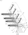
- FIG. 1 is a schematic diagram illustrating a connection relationship between a floating type structure and a carrier according to a first example.
- a floating type structure 100 includes a hull 10, a loading arm 110, a loading arm ascending and descending device E, and a fluid storage tank (not shown).
- the floating type structure 100 may be a floating production storage offloading (FPSO) which produces and stores crude oil.
- FPSO floating production storage offloading
- the technical spirit of the present invention is not limited thereto.
- the floating type structure 100 may provide a fluid, e.g., a liquefied natural gas (LNG), stored in a fluid storage tank (not shown) disposed inside the hull 10 to a carrier 1 through the loading arm 110.
- a fluid e.g., a liquefied natural gas (LNG)
- LNG liquefied natural gas
- a fluid storage tank not shown
- the technical spirit of the present invention is not limited thereto.
- the loading arm 110 may be connected to a manifold 2 installed on the carrier 1 to provide the fluid to the carrier 1.
- the loading arm 110 may be configured with a plurality of arms which are connected to be bendable such that the loading arm 110 may extend in a direction in which the carrier 1 is disposed.
- the loading arm 110 may be fixedly installed on the loading arm ascending and descending device E which is installed on the hull 10. An angle formed by each of the plurality of arms of the loading arm 110 may be adjusted so as to allow the loading arm 110 to be connected to the manifold 2 installed on the carrier 1.
- a height of the loading arm 110 from a top surface of the hull 10 may be adjusted by the loading arm ascending and descending device E which is disposed below the loading arm 110.
- the floating type structure 100 may compensate for a height difference between the floating type structure 100 and the carrier 1 which varies due to sea environmental conditions such as winds, waves, and the like, using the loading arm ascending and descending device E.
- FIGS. 2 to 7 an internal structure and an operation of the floating type structure according to one embodiment of the present invention will be described with reference to FIGS. 2 to 7 .
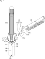
- FIG. 2 is a perspective view for describing an internal structure of the floating type structure by enlarging a portion E of FIG. 1 .
- FIG. 3 is a diagram for describing an arrangement of the floating type structure on a recess.
- FIG. 4 is a perspective view illustrating a loading arm ascending and descending device of the floating type structure.
- FIGS. 5 and 6 are diagrams for describing an operation of a connection pipe according to an operation of the loading arm ascending and descending device of the floating type structure.
- FIG. 7 is a diagram for describing a cylinder cover and a cylinder packing of the floating type structure.
- the floating type structure 100 includes the hull 10, a recess 20, a connection groove 30, a pipe 40, the loading arm 110, a plunger 120, a first connector 121, a plunger base 130, a second connector 131, a cylinder 140, a cylinder cover 150, a cylinder packing 160, a connection pipe 170, a first joint 173, a second joint 174, and a third joint 175.
- the plunger 120 may be connected to the loading arm 110 disposed on the hull 10. Specifically, an upper surface of the plunger 120 may be connected to the loading arm 110, and the plunger 120 may be inserted into the plunger base 130.
- the plunger 120 may include the first connector 121 having a U-shaped groove coupled to a first end of the cylinder 140.
- the plunger 120 may be easily attached to and detached from the first end of the cylinder 140 using the U-shaped groove formed in the first connector 121.
- the plunger base 130 may be disposed in the hull 10. Specifically, the plunger base 130 may be connected to the recess 20 formed in the hull 10, and the plunger 120 may be inserted into the plunger base 130.
- the plunger base 130 may include the second connector 131 having a U-shaped groove coupled to a second end opposite the first end of the cylinder 140.
- the plunger base 130 may be easily attached to and detached from the second end of the cylinder 140 using the U-shaped groove formed in the second connector 131.
- the cylinder 140 may connect the plunger 120 to the plunger base 130. Specifically, the first end of the cylinder 140 may be coupled to the first connector 121 installed on the plunger 120, and the second end of the cylinder 140 may be coupled to the second connector 131 installed on the plunger base 130.
- the cylinder 140 may ascend or descend the plunger 120 using a hydraulic pressure.
- the technical spirit of the present invention is not limited thereto. That is, in some other embodiments, the cylinder 140 may be driven using a mechanical device, e.g., a motor.
- the cylinder 140 may ascend or descend the plunger 120 to thereby ascend or descend the loading arm 110 connected to the plunger 120. Consequently, the floating type structure 100 may adjust the height of the loading arm 110 from the upper surface of the hull 10 using the cylinder 140.
- connection pipe 170 may be connected to the pipe 40 installed on the hull 10 and allow a height from the hull 10 to be adjustable.
- connection pipe 170 may include a first connection pipe 171 connected to the pipe 40 and a second connection pipe 172 for connecting the first connection pipe 171 to the loading arm 110.
- connection pipe 170 may include three or more connection pipes.
- the first connection pipe 171 may be connected to the pipe 40 by the first joint 173 and rotated around the pipe 40.
- the second connection pipe 172 may be connected to the first connection pipe 171 by the second joint 174 and rotated around the first connection pipe 171.
- the second connection pipe 172 may be connected to the loading arm 110 by the third joint 175 and rotated about the loading arm 110.
- the first connection pipe 171 and the second connection pipe 172 may maintain a connection between the loading arm 110 and the pipe 40 using the first, second, and third joints 173, 174, and 175 which perform an articulating function.
- the first connection pipe 171 and the second connection pipe 172 may each have a C shape, and one end of the first connection pipe 171 may be connected to one end of the second connection pipe 172 through the second joint 174.
- FIGS. 5 and 6 The above operations of the first connection pipe 171 and the second connection pipe 172 are shown in FIGS. 5 and 6 .
- FIG. 5 illustrates a state in which the plunger 120 is inserted into the plunger base 130 and thus the loading arm 110 is disposed adjacent to the upper surface of the hull 10.
- the first and second connection pipes 171 and 172 may be formed at a position closer to sea level than the pipe 40.
- the cylinder 140 is operated to ascend the plunger 120 such that the loading arm 110 is ascended from the upper surface of the hull 10.
- first connection pipe 171 may be rotated around the first and second joints 173 and 174
- second connection pipe 172 may be rotated around the second and third joints 174 and 175.
- connection pipe 170 may maintain the connection between the loading arm 110 and the pipe 40.
- connection pipe 170 and the first, second, and third joints 173, 174, and 175 may be disposed in the recess 20 formed in the hull 10.
- connection pipe 170 may maintain the connection between the loading arm 110 and the pipe 40 without interference of the upper surface of the hull 10.
- the cylinder cover 150 includes a first region R1 in which an opening 151 is formed and a second region R2 in which the opening 151 is not formed.
- the second region R2 may include an area that is equal to an area of the opening 151.
- the cylinder 140 may be moved to the connection groove 30 of FIG. 10 into which the second region R2 of the cylinder cover 150 is inserted.
- the cylinder cover 150 may be connected to the cylinder 140 through the opening 151. Specifically, the cylinder cover 150 may surround a side surface of the cylinder 140 which is installed to pass through the opening 151, thereby being connected to the cylinder 140.
- the cylinder cover 150 may be inserted into the connection groove 30 of FIG. 10 formed in a lower surface of the recess 20, which is formed in the hull 10, thereby being coupled to the recess 20. Consequently, the cylinder cover 150 may couple the cylinder 140 to the connection groove 30 of FIG. 10 formed in the recess 20.
- the cylinder packing 160 may be disposed on the cylinder cover 150.
- the cylinder packing 160 may surround a side surface of the cylinder 140 to block seawater from being introduced into the hull 10 through a minute space between the cylinder cover 150 and the cylinder 140.
- FIGS. 8 to 11 are diagrams for describing coupling and release operations of the cylinder.
- the first end of the cylinder 140 coupled to the first connector 121 of the plunger 120 is descended to release the coupling between the first connector 121 and the first end of the cylinder 140.
- the first connector 121 since the first connector 121 has a U shape, the first connector 121 may be easily released from the first end of the cylinder 140.
- the cylinder cover 150 is ascended from the connection groove 30, which is formed in the lower surface of the recess 20 formed in the hull 10 so that the coupling of the cylinder cover 150 to the connection groove 30 is released.
- the cylinder 140 is pivoted around the second connector 131 of the plunger base 130.
- the cylinder 140 is pivoted from one side of the connection groove 30 into which the first region R1 of the cylinder cover 150 is inserted to the other side of the connection groove 30 into which the second region R2 of the cylinder cover 150 is inserted.
- connection groove 30 is formed to be spaced apart from the side wall of the recess 20.
- the second connector 131 since the second connector 131 has a U shape, the second connector 131 may be easily released from the second end of the cylinder 140.
- the above-described operations may be performed to release the couplings between the cylinder 140 and the plunger 120 and between the cylinder 140 and the plunger base 130. Further, the above-described operations may be performed reversely to couple the cylinder 140 to the plunger 120 and the plunger base 130.
- the floating type structure 100 may maintain the connection of the loading arm 110 while compensating for the height difference between the carrier 1 and the floating type structure 100 using the loading arm ascending and descending device E and the connection pipe 170.
- the floating type structure 100 is capable of facilitating maintenance and repair of the cylinder 140 by releasing the coupling of the cylinder 140 using the cylinder cover 150.
- FIGS. 12 to 17 an internal structure and an operation of a floating type structure according to the present invention will be described with reference to FIGS. 12 to 17 .
- FIG. 12 is a perspective view for describing an internal structure of a floating type structure according to the present invention by enlarging the portion E of FIG. 1 .
- FIG. 13 is a diagram for describing an arrangement of the floating type structure on a recess according to the present invention.
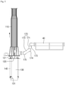
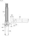
- FIG. 14 is a side view for describing an internal structure of the floating type structure according to the present invention.
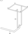
- FIG. 15 is a diagram illustrating a drain pipe of the floating type structure according to another embodiment of the present invention.
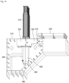
- FIG. 16 is a diagram for describing a function of the drain pipe of the floating type structure according to the present invention.
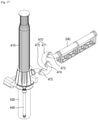
- FIG. 17 is a perspective view illustrating a loading arm ascending and descending device of the floating type structure of the present invention.
- a floating type structure 400 includes a hull 310, a first recess 320, a second recess 330, a pipe 340, a loading arm 410, a plunger 420, a plunger base 430, a pressure adjusting hole 431, a cylinder 440, a drain 450, a first drain pipe 460, a connection pipe 470, a first joint 473, a second joint 474, a third joint 475, and a second drain pipe 480.
- the plunger 420 is connected to the loading arm 410 disposed on the hull 310. Specifically, an upper surface of the plunger 420 may be connected to the loading arm 410, and the plunger 420 may be inserted into the plunger base 430. The plunger 420 is coupled to a first end of the cylinder 440.
- the plunger base 430 is disposed in the hull 310. Specifically, the plunger base 430 is connected to the first recess 320 formed in the hull 310, and the plunger 420 is inserted into the plunger base 430. The plunger base 430 is coupled to a second end of the cylinder 440 opposite the first end thereof.
- the plunger base 430 includes the pressure adjusting hole 431 formed therebelow.
- the plunger base 430 When the plunger 420 is descended in a direction of sea level inside the plunger base 430, the plunger base 430 allows air thereinside to flow out through the pressure adjusting hole 431 along the second drain pipe 480 connected to the pressure adjusting hole 431, thereby adjusting an inner pressure of the plunger base 430.
- the plunger base 430 allows external air to be introduced through the pressure adjusting hole 431 along the second drain pipe 480 connected to the pressure adjusting hole 431, thereby adjusting the inner pressure of the plunger base 430.
- the cylinder 440 connects the plunger 420 to the plunger base 430.
- the first end of the cylinder 440 may be coupled to the plunger 420, and the second end of the cylinder 440 are coupled to the plunger base 430.
- the cylinder 440 may ascend or descend the plunger 420 using a hydraulic pressure.
- the cylinder 440 may be driven using a mechanical device, e.g., a motor.
- the cylinder 440 may ascend or descend the plunger 420 and the loading arm 410 connected to the plunger 420. Consequently, the floating type structure 400 may adjust the height of the loading arm 410 from the upper surface of the hull 310 using the cylinder 440.
- the drain 450 may be formed on a lower surface of the first recess 320 which is formed in the hull 310.
- a plurality of drains 450 may be formed on the lower surface of the first recess 320.
- the plurality of drains 450 may each be formed at an edge of the first recess 320 which does not overlap the plunger base 430 connected to the first recess 320.
- the drains 450 may discharge a fluid, e.g., rainwater or seawater, which is accumulated in the first recess 320 and the second recess 330 adjacent thereto, along the first drain pipe 460 connected to each of the drains 450.
- a fluid e.g., rainwater or seawater
- a lower surface of the second recess 330 is formed to be closer to the upper surface of the hull 310 than the lower surface of the first recess 320.
- a second height h2 from the lower surface of the second recess 330 to the upper surface of the hull 310 may be smaller than a first height h1 from the lower surface of the first recess 320 to the upper surface of the hull 310.
- the fluid accumulated in the first and second recesses 320 and 330 may be discharged through the drains 450 formed in the first recess 320.
- the drains 450 may also be formed in the second recess 330. Further, in some other embodiments, the drains 450 may be formed in only the second recess 330, and the second height h2 from the lower surface of the second recess 330 to the upper surface of the hull 310 may be greater than the first height h1 from the lower surface of the first recess 320 to the upper surface of the hull 310.
- the first drain pipe 460 between each of the drains 450 and the second drain pipe 480.
- the first drain pipe 460 may discharge a fluid, e.g., rainwater or seawater, which is introduced through the drains 450, by providing the fluid to the second drain pipe 480.
- One end of the second drain pipe 480 is connected to the pressure adjusting hole 431 formed at a lower portion of the plunger base 430, and the first drain pipe 460 may be connected to a side surface of second drain pipe 480.
- the second drain pipe 480 allows air to flow in and out the plunger base 430 according to an inner pressure of the plunger base 430.
- the second drain pipe 480 simplifies a drain pipe configuration inside the hull 310 by performing a function of discharging the fluid introduced through the first drain pipe 460 and flowing in the second drain pipe 480 and a function of adjusting the inner pressure of the plunger base 430.
- connection pipe 470 is disposed on the second recess 320.
- the connection pipe 470 may be connected to the pipe 340 installed on the hull 310 and allows a height from the hull 310 to be adjustable.
- connection pipe 470 may include a first connection pipe 471 connected to the pipe 340, and a second connection pipe 472 for connecting the first connection pipe 471 to the loading arm 410.
- connection pipe 470 may include three or more connection pipes.
- the first connection pipe 471 may be connected to the pipe 340 by the first joint 473 and rotated around the pipe 340.
- the second connection pipe 472 may be connected to the first connection pipe 471 by the second joint 474 and rotated around the first connection pipe 471.
- the second connection pipe 472 may be connected to the loading arm 410 by the third joint 475 and rotated about the loading arm 410.
- the first connection pipe 471 and the second connection pipe 472 may maintain a connection between the loading arm 410 and the pipe 340 using the first, second, and third joints 473, 474, and 475 which perform an articulating function.
- the first connection pipe 471 and the second connection pipe 472 may each have a C shape, and one end of the first connection pipe 471 may be connected to one end of the second connection pipe 472 through the second joint 474.
- FIGS. 18 and 19 The above operations of the first connection pipe 471 and the second connection pipe 472 are shown in FIGS. 18 and 19 which will be described below.
- lines e.g., electric lines, hydraulic pressure supply lines, nitrogen lines, and the like
- lines may be installed along the pipe 340 and the connection pipe 470.
- connection pipe according to an ascending or descending operation of a loading arm ascending and descending device of the floating type structure according to another example will be described with reference to FIGS. 18 and 19 .
- FIGS. 18 and 19 are diagrams for describing an operation of a connection pipe according to an operation of the loading arm ascending and descending device of the floating type structure.
- FIG. 18 illustrates a state in which the plunger 420 is inserted into the plunger base 430 and thus the loading arm 410 is disposed adjacent to the upper surface of the hull 310.
- the first and second connection pipes 171 and 172 may be formed at a position closer to sea level than the pipe 340.
- the cylinder 440 is operated to ascend the plunger 420 such that the loading arm 410 is ascended from the upper surface of the hull 310.
- first connection pipe 471 may be rotated around the first and second joints 473 and 474
- second connection pipe 472 may be rotated around the second and third joints 474 and 475.
- connection pipe 470 may maintain the connection between the loading arm 410 and the pipe 340.
- connection pipe 470 and the first, second, and third joints 473, 474, and 475 may be disposed in the second recess 330 formed in the hull 310.
- connection pipe 470 may maintain the connection between the loading arm 410 and the pipe 340 without interference of the upper surface of the hull 310.
- the floating type structure 400 may maintain the connection of the loading arm 410 while compensating for the height difference between the carrier 1 and the floating type structure 400 using the loading arm ascending and descending device E and the connection pipe 470.
- the floating type structure 400 may simplify the drain pipe configuration inside the hull 310 by performing a function of discharging the fluid accumulated in the first and second recesses 320 and 330 in the hull 310 and a function of adjusting the inner pressure of the plunger base 430 using the second drain pipe 480 connected to the first drain pipe 460.
Landscapes
- Engineering & Computer Science (AREA)
- Mechanical Engineering (AREA)
- Chemical & Material Sciences (AREA)
- Combustion & Propulsion (AREA)
- Ocean & Marine Engineering (AREA)
- Vibration Prevention Devices (AREA)
- Jib Cranes (AREA)
- Bridges Or Land Bridges (AREA)
- Earth Drilling (AREA)
- Valve-Gear Or Valve Arrangements (AREA)
- Filling Or Discharging Of Gas Storage Vessels (AREA)
Description
- The present invention relates to a floating type structure.
- Liquefied natural gas (LNG) is a colorless transparent liquid obtained by cooling and liquefying natural gas (NG), which contains methane as a main component, at about -162 °C. LNG has a volume which is about 1/600 that of NG.
- Therefore, when NG is liquefied into LNG, NG may be transported efficiently. For example, an LNG carrier which can transport (carry) LNG by sea is used.
- Recently, an LNG floating, production, storage, and offloading (LNG FPSO) unit has been used to collect, liquefy, and store NG at sea.
- The LNG FPSO is moored at a specific point in the sea, collects NG from a gas well of the ocean bed, liquefies the collected NG, and then stores the LNG in a storage tank. The LNG stored in the LNG FPSO may be moved to the LNG carrier and transported to a destination.
- In this case, the LNG stored in the LNG FPSO is moved to the LNG carrier in a state in which the LNG carrier is moored to the LNG FPSO. To this end, a loading arm may be installed on the LNG FPSO, a manifold corresponding to the loading arm may be installed on the LNG carrier, and the loading arm may be connected to the manifold to transfer the LNG to the LNG carrier.
- However, the transferring of the LNG is carried out in a state in which both of the LNG FPSO and the LNG carrier are floating on the sea. In this case, the LNG FPSO and the LNG carrier move independently according to sea conditions such as winds, waves, and the like. That is, the LNG FPSO and the LNG carrier exhibit different motion responses according to a surrounding environment such that excessive vertical relative movements occur. Consequently, it is very difficult to connect the loading arm of the LNG FPSO to the manifold of the LNG carrier, and there is a problem in that an impact is applied to a connected portion, or a coupling therebetween is loosed.
-
Korean Patent Registration No. 10-1301999 (Issued Date: September 02, 2013 KR 2012 0050791 A1 - The present invention is directed to providing a floating type structure which is capable of maintaining a connection of a loading arm while compensating for a height difference between a carrier and the floating type structure using a loading arm ascending and descending device and a connection pipe.
- In addition, the present invention is directed to providing a floating type structure which is capable of facilitating maintenance and repair of a cylinder by releasing a coupling of the cylinder using a cylinder cover.
- Further, the present invention is directed to providing a floating type structure which is capable of performing a function of discharging a fluid accumulated on a hull and a function of controlling a pressure in a plunger base through a single drain pipe.
- The problems to be solved by the present invention are not limited to those described above, and other problems not mentioned above should be clearly understood by those skilled in the art from the following description.
- The claimed invention provides a floating type structure comprising:
- a hull;
- a recess formed in the hull;
- a loading arm provided on the hull;
- a plunger connected to the loading arm;
- a plunger base which is connected to the recess formed in the hull, into which the plunger is inserted, and which includes a pressure adjusting hole formed at a lower portion of the plunger base;
- a cylinder which connects the plunger to the plunger base and adjusts a height of the loading arm, wherein the plunger is coupled to a first end of the cylinder and the plunger base is coupled to a second end of the cylinder opposite said first end to ascend or descend the plunger inside the plunger base;a drain formed in the recess;
- a first drain pipe that is connected to the drain and discharges a fluid accumulated in the recess; and
- a second drain pipe connected to the pressure adjusting hole allowing air to flow in and out the plunger base; and
- a connection pipe which connects a pipe installed on the hull to the loading arm and which allows a height from the hull to be adjustable,
- wherein the first drain pipe is connected to the second drain pipe; and
- the second drain pipe discharges the fluid introduced from the first drain pipe, wherein the recess includes:
- a first recess in which the loading arm is disposed; and
- a second recess in which the connection pipe is disposed,wherein a lower surface of the second recess is formed to be closer to an upper surface of the hull than a lower surface of the first recess; an
- the drain is formed in the first recess.
- A first example, not claimed, provides a floating type structure including a loading arm, a plunger connected to the loading arm, a plunger base which is connected to a recess formed in a hull and into which the plunger is inserted, a cylinder which connects the plunger to the plunger base and adjusts a height of the loading arm, and a cylinder cover including a first region in which an opening is formed and a second region in which an opening is not formed, connected to the cylinder through the opening, and inserted into a connection groove formed in the recess to couple the cylinder to the recess.
- The cylinder may be pivoted from one side of the connection groove, into which the first region of the cylinder cover is inserted, to the other side of the connection groove into which the second region of the cylinder cover is inserted such that the coupling between the cylinder and the plunger base may be released.
- The plunger may include a first connector having a U-shaped groove, the plunger base may include a second connector having a U-shaped groove, the first connector may be coupled to a first end of the cylinder, and the second connector is coupled to a second end of the cylinder.
- The floating type structure may further include a cylinder packing disposed on the cylinder cover and configured to block seawater from being introduced into the hull.
- The floating type structure may further include a connection pipe which connects a pipe installed on the hull to the loading arm and which allows a height from the hull to be adjustable.
- The connection pipe may include a first connection pipe connected to the pipe and a second connection pipe which connects the first connection pipe to the loading arm, wherein the first connection pipe may be connected to the pipe by a first joint and rotated around the pipe, the second connection pipe may be connected to the first connection pipe by a second joint and rotated around the first connection pipe, and the second connection pipe may be connected to the loading arm by a third joint and rotated around the loading arm.
- The recess may include a plurality of drains, and each of the plurality of drains may be formed at an edge of the recess which does not overlap the plunger base.
- A second example, not claimed, provides a floating type structure including a first recess formed in a hull and having a first depth, a second recess formed in the hull and having a depth that is smaller than the first depth, a pipe installed on the hull, a loading arm installed in the first recess, a cylinder installed at a lower portion of the first recess and configured to adjust a height of the loading arm, and a connector that is installed in the second recess, connects the pipe to the loading arm, and includes a first connection pipe and a second connection pipe which have a C shape and are connected to each other.
- The connector may include the first connection pipe connected to the pipe, and the second connection pipe which connects the first connection pipe to the loading arm, wherein the first connection pipe may be connected to the pipe by a first joint and rotated around the pipe, the second connection pipe may be connected to the first connection pipe by a second joint and rotated around the first connection pipe, and the second connection pipe may be connected to the loading arm by a third joint and rotated around the loading arm.
- The details of other embodiments are included in the detailed description and the drawings.
-
-
FIG. 1 is a schematic diagram illustrating a connection relationship between a floating type structure and a carrier according to a first example of the present invention. -
FIG. 2 is a perspective view for describing an internal structure of the floating type structure by enlarging a portion E ofFIG. 1 . -
FIG. 3 is a diagram for describing an arrangement of the floating type structure on a -
FIG. 4 is a perspective view illustrating a loading arm ascending and descending device of the floating type structure. -
FIGS. 5 and6 are diagrams for describing an operation of a connection pipe according to an operation of the loading arm ascending and descending device of the floating type structure. -
FIG. 7 is a diagram for describing a cylinder cover and a cylinder packing of the floating type structure. -
FIGS. 8 to 11 are diagrams for describing coupling and decoupling operations of the cylinder in the floating type structure. -
FIG. 12 is a perspective view for describing an internal structure of a floating type structure according to the present invention by enlarging the portion E ofFIG. 1 . -
FIG. 13 is a diagram for describing an arrangement of the floating type structure on a recess according to the present invention. -
FIG. 14 is a side view for describing an internal structure of the floating type structure according to the present invention. -
FIG. 15 is a diagram illustrating a drain pipe of the floating type structure according the present invention. -
FIG. 16 is a diagram for describing a function of the drain pipe of the floating type structure according to another embodiment of the present invention. -
FIG. 17 is a perspective view illustrating a loading arm ascending and descending device of the floating type structure according to another example of the present invention. -
FIGS. 18 and19 are diagrams for describing an operation of a connection pipe according to an operation of the loading arm ascending and descending device of the floating type structure. - Hereinafter, exemplary embodiments will be described in detail with reference to the accompanying drawings. The advantages and features of the present invention and the manner of achieving the advantages and features will become apparent with reference to the embodiments described in detail below with the accompanying drawings. The present invention may, however, be implemented in many different forms and should not be construed as being limited to the embodiments set forth herein, and the embodiments are provided such that the present invention will be thorough and complete and will fully convey the scope of the present invention to those skilled in the art, and the present invention is defined by only the scope of the appended claims. The same reference numerals refer to the same components throughout the present invention.
- Although the terms first, second, and the like are used to describe various components, these components are not substantially limited by these terms. These terms are used only to distinguish one component from another component. Therefore, a first component described below may be substantially a second component within the technical spirit of the present invention.
- Terms used herein are intended to describe embodiments and are not intended to limit the present invention. In the present invention, the singular forms include the plural forms unless the context clearly dictates otherwise. It is noted that the terms "comprises" and/or "comprising" used herein do not exclude the presence or addition of one or more other components, steps, operations, and/or elements in addition to stated components, steps, operations, and/or elements.
- Unless defined otherwise, all terms (including technical and scientific terms) used herein may be used in a sense commonly understood by those skilled in the art to which the present invention pertains. Further, terms which are defined in a commonly used dictionary are not ideally or excessively interpreted unless explicitly defined otherwise.
- Hereinafter, exemplary embodiments of the present invention will be described in detail with reference to the accompanying drawings. The same reference numerals are assigned to the same or corresponding components regardless of reference numerals, and a duplicate description thereof will be omitted.
- Hereinafter, a connection relationship between a floating type structure and a carrier according to one embodiment of the present invention will be described with reference to
FIG. 1 . -
FIG. 1 is a schematic diagram illustrating a connection relationship between a floating type structure and a carrier according to a first example. - Referring to
FIG. 1 , a floatingtype structure 100 according to one embodiment of the present invention includes ahull 10, aloading arm 110, a loading arm ascending and descending device E, and a fluid storage tank (not shown). - For example, the floating
type structure 100 may be a floating production storage offloading (FPSO) which produces and stores crude oil. However, the technical spirit of the present invention is not limited thereto. - The floating
type structure 100 may provide a fluid, e.g., a liquefied natural gas (LNG), stored in a fluid storage tank (not shown) disposed inside thehull 10 to a carrier 1 through theloading arm 110. However, the technical spirit of the present invention is not limited thereto. - In this case, the
loading arm 110 may be connected to amanifold 2 installed on the carrier 1 to provide the fluid to the carrier 1. - Specifically, the
loading arm 110 may be configured with a plurality of arms which are connected to be bendable such that theloading arm 110 may extend in a direction in which the carrier 1 is disposed. Theloading arm 110 may be fixedly installed on the loading arm ascending and descending device E which is installed on thehull 10. An angle formed by each of the plurality of arms of theloading arm 110 may be adjusted so as to allow theloading arm 110 to be connected to themanifold 2 installed on the carrier 1. - A height of the
loading arm 110 from a top surface of thehull 10 may be adjusted by the loading arm ascending and descending device E which is disposed below theloading arm 110. Thus, the floatingtype structure 100 may compensate for a height difference between the floatingtype structure 100 and the carrier 1 which varies due to sea environmental conditions such as winds, waves, and the like, using the loading arm ascending and descending device E. - Hereinafter, an internal structure and an operation of the floating type structure according to one embodiment of the present invention will be described with reference to
FIGS. 2 to 7 . -
FIG. 2 is a perspective view for describing an internal structure of the floating type structure by enlarging a portion E ofFIG. 1 .FIG. 3 is a diagram for describing an arrangement of the floating type structure on a recess. -
FIG. 4 is a perspective view illustrating a loading arm ascending and descending device of the floating type structure. -
FIGS. 5 and6 are diagrams for describing an operation of a connection pipe according to an operation of the loading arm ascending and descending device of the floating type structure.FIG. 7 is a diagram for describing a cylinder cover and a cylinder packing of the floating type structure. - Referring to
FIGS. 2 to 7 , the floatingtype structure 100 includes thehull 10, arecess 20, aconnection groove 30, apipe 40, theloading arm 110, aplunger 120, afirst connector 121, aplunger base 130, asecond connector 131, acylinder 140, acylinder cover 150, a cylinder packing 160, aconnection pipe 170, a first joint 173, a second joint 174, and a third joint 175. - The
plunger 120 may be connected to theloading arm 110 disposed on thehull 10. Specifically, an upper surface of theplunger 120 may be connected to theloading arm 110, and theplunger 120 may be inserted into theplunger base 130. - The
plunger 120 may include thefirst connector 121 having a U-shaped groove coupled to a first end of thecylinder 140. Theplunger 120 may be easily attached to and detached from the first end of thecylinder 140 using the U-shaped groove formed in thefirst connector 121. - The
plunger base 130 may be disposed in thehull 10. Specifically, theplunger base 130 may be connected to therecess 20 formed in thehull 10, and theplunger 120 may be inserted into theplunger base 130. - The
plunger base 130 may include thesecond connector 131 having a U-shaped groove coupled to a second end opposite the first end of thecylinder 140. Theplunger base 130 may be easily attached to and detached from the second end of thecylinder 140 using the U-shaped groove formed in thesecond connector 131. - The
cylinder 140 may connect theplunger 120 to theplunger base 130. Specifically, the first end of thecylinder 140 may be coupled to thefirst connector 121 installed on theplunger 120, and the second end of thecylinder 140 may be coupled to thesecond connector 131 installed on theplunger base 130. - For example, the
cylinder 140 may ascend or descend theplunger 120 using a hydraulic pressure. However, the technical spirit of the present invention is not limited thereto. That is, in some other embodiments, thecylinder 140 may be driven using a mechanical device, e.g., a motor. - The
cylinder 140 may ascend or descend theplunger 120 to thereby ascend or descend theloading arm 110 connected to theplunger 120. Consequently, the floatingtype structure 100 may adjust the height of theloading arm 110 from the upper surface of thehull 10 using thecylinder 140. - The
connection pipe 170 may be connected to thepipe 40 installed on thehull 10 and allow a height from thehull 10 to be adjustable. - Specifically, the
connection pipe 170 may include afirst connection pipe 171 connected to thepipe 40 and asecond connection pipe 172 for connecting thefirst connection pipe 171 to theloading arm 110. However, the technical spirit of the present invention is not limited thereto. That is, in some other embodiments, theconnection pipe 170 may include three or more connection pipes. - The
first connection pipe 171 may be connected to thepipe 40 by the first joint 173 and rotated around thepipe 40. Thesecond connection pipe 172 may be connected to thefirst connection pipe 171 by the second joint 174 and rotated around thefirst connection pipe 171. Thesecond connection pipe 172 may be connected to theloading arm 110 by the third joint 175 and rotated about theloading arm 110. - Even when the
loading arm 110 is ascended from the upper surface of thehull 10, thefirst connection pipe 171 and thesecond connection pipe 172 may maintain a connection between theloading arm 110 and thepipe 40 using the first, second, andthird joints first connection pipe 171 and thesecond connection pipe 172 may each have a C shape, and one end of thefirst connection pipe 171 may be connected to one end of thesecond connection pipe 172 through thesecond joint 174. - The above operations of the
first connection pipe 171 and thesecond connection pipe 172 are shown inFIGS. 5 and6 . -
FIG. 5 illustrates a state in which theplunger 120 is inserted into theplunger base 130 and thus theloading arm 110 is disposed adjacent to the upper surface of thehull 10. In this case, the first andsecond connection pipes pipe 40. - As shown in
FIG. 6 , thecylinder 140 is operated to ascend theplunger 120 such that theloading arm 110 is ascended from the upper surface of thehull 10. - In this case, the
first connection pipe 171 may be rotated around the first andsecond joints second connection pipe 172 may be rotated around the second andthird joints - Consequently, the
connection pipe 170 may maintain the connection between theloading arm 110 and thepipe 40. - As shown in
FIG. 3 , theconnection pipe 170 and the first, second, andthird joints recess 20 formed in thehull 10. - Consequently, even though the
loading arm 110 is ascended or descended, theconnection pipe 170 may maintain the connection between theloading arm 110 and thepipe 40 without interference of the upper surface of thehull 10. - Referring to
FIGS. 2 and7 , thecylinder cover 150 includes a first region R1 in which anopening 151 is formed and a second region R2 in which theopening 151 is not formed. - In this case, the second region R2 may include an area that is equal to an area of the
opening 151. Thus, as described below, when the coupling of thecylinder 140 is released, thecylinder 140 may be moved to theconnection groove 30 ofFIG. 10 into which the second region R2 of thecylinder cover 150 is inserted. - The
cylinder cover 150 may be connected to thecylinder 140 through theopening 151. Specifically, thecylinder cover 150 may surround a side surface of thecylinder 140 which is installed to pass through theopening 151, thereby being connected to thecylinder 140. - The
cylinder cover 150 may be inserted into theconnection groove 30 ofFIG. 10 formed in a lower surface of therecess 20, which is formed in thehull 10, thereby being coupled to therecess 20. Consequently, thecylinder cover 150 may couple thecylinder 140 to theconnection groove 30 ofFIG. 10 formed in therecess 20. - Referring to
FIG. 7 , the cylinder packing 160 may be disposed on thecylinder cover 150. The cylinder packing 160 may surround a side surface of thecylinder 140 to block seawater from being introduced into thehull 10 through a minute space between thecylinder cover 150 and thecylinder 140. - Hereinafter, coupling and release operations of a cylinder in the floating type structure according to one embodiment of the present invention will be described with reference to
FIGS. 7 to 11 . -
FIGS. 8 to 11 are diagrams for describing coupling and release operations of the cylinder. - Referring to
FIGS. 8 and9 first, when the coupling of thecylinder 140 is released, theplunger 120 is descended to a lowest position. - Then, the first end of the
cylinder 140 coupled to thefirst connector 121 of theplunger 120 is descended to release the coupling between thefirst connector 121 and the first end of thecylinder 140. In this case, as described above, since thefirst connector 121 has a U shape, thefirst connector 121 may be easily released from the first end of thecylinder 140. - Referring to
FIGS. 9 and10 , thecylinder cover 150 is ascended from theconnection groove 30, which is formed in the lower surface of therecess 20 formed in thehull 10 so that the coupling of thecylinder cover 150 to theconnection groove 30 is released. - Referring to
FIGS. 7 ,10 , and11 , thecylinder 140 is pivoted around thesecond connector 131 of theplunger base 130. - Specifically, the
cylinder 140 is pivoted from one side of theconnection groove 30 into which the first region R1 of thecylinder cover 150 is inserted to the other side of theconnection groove 30 into which the second region R2 of thecylinder cover 150 is inserted. - In this case, as shown in
FIG. 3 , in order to avoid interference between thecylinder cover 150 being moved and a side wall of therecess 20, theconnection groove 30 is formed to be spaced apart from the side wall of therecess 20. - Then, the second end of the
cylinder 140 coupled to thesecond connector 131 of theplunger base 130 is ascended to release the coupling between thesecond connector 131 and the second end of thecylinder 140. - In this case, as described above, since the
second connector 131 has a U shape, thesecond connector 131 may be easily released from the second end of thecylinder 140. - The above-described operations may be performed to release the couplings between the
cylinder 140 and theplunger 120 and between thecylinder 140 and theplunger base 130. Further, the above-described operations may be performed reversely to couple thecylinder 140 to theplunger 120 and theplunger base 130. - The floating
type structure 100 according to the first example may maintain the connection of theloading arm 110 while compensating for the height difference between the carrier 1 and the floatingtype structure 100 using the loading arm ascending and descending device E and theconnection pipe 170. - Further, the floating
type structure 100 according to the first example is capable of facilitating maintenance and repair of thecylinder 140 by releasing the coupling of thecylinder 140 using thecylinder cover 150. - Hereinafter, an internal structure and an operation of a floating type structure according to the present invention will be described with reference to
FIGS. 12 to 17 . -
FIG. 12 is a perspective view for describing an internal structure of a floating type structure according to the present invention by enlarging the portion E ofFIG. 1 .FIG. 13 is a diagram for describing an arrangement of the floating type structure on a recess according to the present invention.FIG. 14 is a side view for describing an internal structure of the floating type structure according to the present invention.FIG. 15 is a diagram illustrating a drain pipe of the floating type structure according to another embodiment of the present invention.FIG. 16 is a diagram for describing a function of the drain pipe of the floating type structure according to the present invention.FIG. 17 is a perspective view illustrating a loading arm ascending and descending device of the floating type structure of the present invention. - Referring to
FIGS. 12 to 17 , a floating type structure 400 according to the present invention includes ahull 310, afirst recess 320, asecond recess 330, apipe 340, aloading arm 410, aplunger 420, aplunger base 430, apressure adjusting hole 431, acylinder 440, adrain 450, afirst drain pipe 460, aconnection pipe 470, a first joint 473, a second joint 474, a third joint 475, and asecond drain pipe 480. - The
plunger 420 is connected to theloading arm 410 disposed on thehull 310. Specifically, an upper surface of theplunger 420 may be connected to theloading arm 410, and theplunger 420 may be inserted into theplunger base 430. Theplunger 420 is coupled to a first end of thecylinder 440. - The
plunger base 430 is disposed in thehull 310. Specifically, theplunger base 430 is connected to thefirst recess 320 formed in thehull 310, and theplunger 420 is inserted into theplunger base 430. Theplunger base 430 is coupled to a second end of thecylinder 440 opposite the first end thereof. - Referring to
FIG. 16 , theplunger base 430 includes thepressure adjusting hole 431 formed therebelow. - When the
plunger 420 is descended in a direction of sea level inside theplunger base 430, theplunger base 430 allows air thereinside to flow out through thepressure adjusting hole 431 along thesecond drain pipe 480 connected to thepressure adjusting hole 431, thereby adjusting an inner pressure of theplunger base 430. - Further, when the
plunger 420 is ascended from inside theplunger base 430 toward a position of an upper surface of thehull 310, theplunger base 430 allows external air to be introduced through thepressure adjusting hole 431 along thesecond drain pipe 480 connected to thepressure adjusting hole 431, thereby adjusting the inner pressure of theplunger base 430. - The
cylinder 440 connects theplunger 420 to theplunger base 430. - Specifically, the first end of the
cylinder 440 may be coupled to theplunger 420, and the second end of thecylinder 440 are coupled to theplunger base 430. - For example, the
cylinder 440 may ascend or descend theplunger 420 using a hydraulic pressure. However, in some other embodiments, thecylinder 440 may be driven using a mechanical device, e.g., a motor. - The
cylinder 440 may ascend or descend theplunger 420 and theloading arm 410 connected to theplunger 420. Consequently, the floating type structure 400 may adjust the height of theloading arm 410 from the upper surface of thehull 310 using thecylinder 440. - The
drain 450 may be formed on a lower surface of thefirst recess 320 which is formed in thehull 310. A plurality ofdrains 450 may be formed on the lower surface of thefirst recess 320. - As shown in
FIG. 13 , the plurality ofdrains 450 may each be formed at an edge of thefirst recess 320 which does not overlap theplunger base 430 connected to thefirst recess 320. - The
drains 450 may discharge a fluid, e.g., rainwater or seawater, which is accumulated in thefirst recess 320 and thesecond recess 330 adjacent thereto, along thefirst drain pipe 460 connected to each of thedrains 450. - Referring to
FIG. 14 , a lower surface of thesecond recess 330 is formed to be closer to the upper surface of thehull 310 than the lower surface of thefirst recess 320. - Specifically, a second height h2 from the lower surface of the
second recess 330 to the upper surface of thehull 310 may be smaller than a first height h1 from the lower surface of thefirst recess 320 to the upper surface of thehull 310. - Consequently, even when a separate drain is not installed in the
second recess 330, the fluid accumulated in the first andsecond recesses drains 450 formed in thefirst recess 320. - However, in some other embodiments, the
drains 450 may also be formed in thesecond recess 330. Further, in some other embodiments, thedrains 450 may be formed in only thesecond recess 330, and the second height h2 from the lower surface of thesecond recess 330 to the upper surface of thehull 310 may be greater than the first height h1 from the lower surface of thefirst recess 320 to the upper surface of thehull 310. - Referring to
FIGS. 14 to 16 , thefirst drain pipe 460 between each of thedrains 450 and thesecond drain pipe 480. Thefirst drain pipe 460 may discharge a fluid, e.g., rainwater or seawater, which is introduced through thedrains 450, by providing the fluid to thesecond drain pipe 480. - One end of the
second drain pipe 480 is connected to thepressure adjusting hole 431 formed at a lower portion of theplunger base 430, and thefirst drain pipe 460 may be connected to a side surface ofsecond drain pipe 480. - The
second drain pipe 480 allows air to flow in and out theplunger base 430 according to an inner pressure of theplunger base 430. - The
second drain pipe 480 simplifies a drain pipe configuration inside thehull 310 by performing a function of discharging the fluid introduced through thefirst drain pipe 460 and flowing in thesecond drain pipe 480 and a function of adjusting the inner pressure of theplunger base 430. - The
connection pipe 470 is disposed on thesecond recess 320. Theconnection pipe 470 may be connected to thepipe 340 installed on thehull 310 and allows a height from thehull 310 to be adjustable. - Specifically, the
connection pipe 470 may include afirst connection pipe 471 connected to thepipe 340, and asecond connection pipe 472 for connecting thefirst connection pipe 471 to theloading arm 410. However, the technical spirit of the present invention is not limited thereto. That is, in some other embodiments, theconnection pipe 470 may include three or more connection pipes. - The
first connection pipe 471 may be connected to thepipe 340 by the first joint 473 and rotated around thepipe 340. Thesecond connection pipe 472 may be connected to thefirst connection pipe 471 by the second joint 474 and rotated around thefirst connection pipe 471. Thesecond connection pipe 472 may be connected to theloading arm 410 by the third joint 475 and rotated about theloading arm 410. - Even when the
loading arm 410 is ascended from the upper surface of thehull 310, thefirst connection pipe 471 and thesecond connection pipe 472 may maintain a connection between theloading arm 410 and thepipe 340 using the first, second, andthird joints first connection pipe 471 and thesecond connection pipe 472 may each have a C shape, and one end of thefirst connection pipe 471 may be connected to one end of thesecond connection pipe 472 through thesecond joint 474. - The above operations of the
first connection pipe 471 and thesecond connection pipe 472 are shown inFIGS. 18 and19 which will be described below. - Although not shown in the drawings, lines (e.g., electric lines, hydraulic pressure supply lines, nitrogen lines, and the like) may be installed along the
pipe 340 and theconnection pipe 470. - Hereinafter, an operation of a connection pipe according to an ascending or descending operation of a loading arm ascending and descending device of the floating type structure according to another example will be described with reference to
FIGS. 18 and19 . -
FIGS. 18 and19 are diagrams for describing an operation of a connection pipe according to an operation of the loading arm ascending and descending device of the floating type structure. -
FIG. 18 illustrates a state in which theplunger 420 is inserted into theplunger base 430 and thus theloading arm 410 is disposed adjacent to the upper surface of thehull 310. In this case, the first andsecond connection pipes pipe 340. - As shown in
FIG. 19 , thecylinder 440 is operated to ascend theplunger 420 such that theloading arm 410 is ascended from the upper surface of thehull 310. - In this case, the
first connection pipe 471 may be rotated around the first andsecond joints second connection pipe 472 may be rotated around the second andthird joints - Consequently, the
connection pipe 470 may maintain the connection between theloading arm 410 and thepipe 340. - As shown in
FIG. 13 , theconnection pipe 470 and the first, second, andthird joints second recess 330 formed in thehull 310. - Consequently, even though the
loading arm 410 is ascended or descended, theconnection pipe 470 may maintain the connection between theloading arm 410 and thepipe 340 without interference of the upper surface of thehull 310. - The floating type structure 400 according to another example may maintain the connection of the
loading arm 410 while compensating for the height difference between the carrier 1 and the floating type structure 400 using the loading arm ascending and descending device E and theconnection pipe 470. - Further, the floating type structure 400 according to another example may simplify the drain pipe configuration inside the
hull 310 by performing a function of discharging the fluid accumulated in the first andsecond recesses hull 310 and a function of adjusting the inner pressure of theplunger base 430 using thesecond drain pipe 480 connected to thefirst drain pipe 460. - While the present invention has been described with reference to the accompanying drawings, those skilled in the art can understand that the present invention can be implemented in other specific forms.
Claims (2)
- A floating type structure comprising:a hull (310);a recess (20, 320) formed in the hull (310);a loading arm (410) provided on the hull;a plunger (420) connected to the loading arm (410);a plunger base (430) which is connected to the recess formed (20, 320, 330) in the hull (310), into which the plunger (420) is inserted, and which includes a pressure adjusting hole (431) formed at a lower portion of the plunger base (430);a cylinder (440) which connects the plunger (420) to the plunger base (430) and adjusts a height of the loading arm (410), wherein the plunger (420) is coupled to a first end of the cylinder (440) and the plunger base (430) is coupled to a second end of the cylinder (440) opposite said first end to ascend or descend the plunger (420) inside the plunger base (430);a drain formed in the recess (320);a first drain pipe (460) that is connected to the drain and discharges a fluid accumulated in the recess (320); anda second drain pipe (480) connected to the pressure adjusting hole allowing air to flow in and out the plunger base (430); anda connection pipe which connects a pipe installed on the hull (310) to the loading arm (410) and which allows a height from the hull (310) to be adjustable,wherein the first drain pipe (460) is connected to the second drain pipe (480); andthe second drain pipe (480) discharges the fluid introduced from the first drain pipe (460), wherein the recess includes:a first recess in which the loading arm (410) is disposed; anda second recess in which the connection pipe is disposed,wherein a lower surface of the second recess is formed to be closer to an upper surface of the hull (310) than a lower surface of the first recess; andthe drain is formed in the first recess.
- The floating type structure of claim 1, wherein:the recess (320) includes a plurality of drains; andeach of the plurality of drains is formed at an edge of the recess which does not overlap the plunger base (430).
Applications Claiming Priority (3)
| Application Number | Priority Date | Filing Date | Title |
|---|---|---|---|
| KR1020170006911A KR101824146B1 (en) | 2017-01-16 | 2017-01-16 | Floating structure |
| KR1020170006912A KR101863843B1 (en) | 2017-01-16 | 2017-01-16 | Floating structure |
| PCT/KR2017/008431 WO2018131765A1 (en) | 2017-01-16 | 2017-08-04 | Floating type structure |
Publications (3)
| Publication Number | Publication Date |
|---|---|
| EP3569486A1 EP3569486A1 (en) | 2019-11-20 |
| EP3569486A4 EP3569486A4 (en) | 2021-02-24 |
| EP3569486B1 true EP3569486B1 (en) | 2022-01-26 |
Family
ID=62840626
Family Applications (1)
| Application Number | Title | Priority Date | Filing Date |
|---|---|---|---|
| EP17891680.5A Active EP3569486B1 (en) | 2017-01-16 | 2017-08-04 | Floating type structure |
Country Status (4)
| Country | Link |
|---|---|
| EP (1) | EP3569486B1 (en) |
| CN (1) | CN110167836B (en) |
| SG (1) | SG11201906118VA (en) |
| WO (1) | WO2018131765A1 (en) |
Family Cites Families (19)
| Publication number | Priority date | Publication date | Assignee | Title |
|---|---|---|---|---|
| US4202372A (en) * | 1976-12-01 | 1980-05-13 | Fmc Corporation | Articulated fluid conduit with auxiliary support |
| US6851994B2 (en) * | 2002-03-08 | 2005-02-08 | Fmc Technologies, Inc. | Disconnectable mooring system and LNG transfer system and method |
| KR20030094983A (en) * | 2002-06-11 | 2003-12-18 | 라근팔 | Cylinder for impact assimilation |
| KR100641747B1 (en) * | 2003-12-01 | 2006-11-02 | 송병목 | Folding lamp posts and their repair method and apparatus |
| GB2420634A (en) * | 2004-11-24 | 2006-05-31 | Perry Slingsby Systems Ltd | Control system for articulated manipulator arm |
| FR2902411B1 (en) * | 2006-06-19 | 2011-02-25 | Technip France | DEVICE FOR TRANSFERRING A FLUID TO A VESSEL, ASSEMBLY AND TRANSFER METHOD THEREOF |
| FR2903653B1 (en) * | 2006-07-13 | 2009-04-10 | Eurodim Sa | SYSTEM FOR TRANSFERRING A FLUID SUCH AS LIQUEFIED NATURAL GAS BETWEEN A SHIP, SUCH AS A SHUTTLE METHANIER AND A FLOATING OR FIXED UNIT. |
| FR2931451B1 (en) * | 2008-05-22 | 2010-12-17 | Fmc Technologies Sa | CONTROL DEVICE FOR SYSTEM FOR LOADING AND / OR UNLOADING FLUIDS |
| CN201242500Y (en) * | 2008-07-31 | 2009-05-20 | 比亚迪股份有限公司 | Durability test apparatus for vehicle door assembly |
| KR101259628B1 (en) * | 2010-09-30 | 2013-04-29 | 삼성중공업 주식회사 | Method for controlling position of gas transference portion |
| KR101188810B1 (en) * | 2010-10-07 | 2012-10-09 | 현대삼호중공업 주식회사 | Hose drain plug for scupper |
| KR101185528B1 (en) * | 2010-11-11 | 2012-09-24 | 삼성중공업 주식회사 | Floating structure and control method thereof |
| KR101301999B1 (en) | 2011-11-23 | 2013-09-02 | 삼성중공업 주식회사 | Floating Body |
| KR101464135B1 (en) * | 2011-12-26 | 2014-11-21 | 현대중공업 주식회사 | Manufacturing zig for cylinder cover |
| KR20140003208U (en) * | 2012-11-16 | 2014-05-30 | 대우조선해양 주식회사 | The Water Tight Structure of Wire Rope Through Hole |
| KR101505458B1 (en) * | 2013-06-12 | 2015-03-25 | 삼성중공업 주식회사 | Manifold device |
| EP2881317A1 (en) * | 2013-12-05 | 2015-06-10 | Caterpillar Propulsion Production AB | A sealing assembly for a retractable thruster |
| SE538470C2 (en) * | 2014-02-21 | 2016-07-12 | Celective Source Ab | Procedure for establishing a temporary connection |
| CN205765123U (en) * | 2016-06-28 | 2016-12-07 | 章文渊 | Piece-holder frame |
-
2017
- 2017-08-04 CN CN201780082616.XA patent/CN110167836B/en active Active
- 2017-08-04 SG SG11201906118VA patent/SG11201906118VA/en unknown
- 2017-08-04 EP EP17891680.5A patent/EP3569486B1/en active Active
- 2017-08-04 WO PCT/KR2017/008431 patent/WO2018131765A1/en not_active Ceased
Also Published As
| Publication number | Publication date |
|---|---|
| EP3569486A1 (en) | 2019-11-20 |
| EP3569486A4 (en) | 2021-02-24 |
| SG11201906118VA (en) | 2019-08-27 |
| CN110167836A (en) | 2019-08-23 |
| CN110167836B (en) | 2021-09-14 |
| WO2018131765A1 (en) | 2018-07-19 |
Similar Documents
| Publication | Publication Date | Title |
|---|---|---|
| US7174930B2 (en) | Connector for articulated hydrocarbon fluid transfer arm | |
| EP1248723B1 (en) | Multi-rov delivery system and method | |
| US9074428B2 (en) | Connector for steel catenary riser to flexible line without stress-joint or flex-joint | |
| US7225877B2 (en) | Subsea intervention fluid transfer system | |
| US7572085B2 (en) | Device for upper connection between two submarine fluid transporting pipelines | |
| US20140318666A1 (en) | Fluid transfer hose manipulator and method of transferring a fluid | |
| NO318688B1 (en) | Riser system, and method of mounting a riser system, to connect an installation on the seabed to a floating vessel | |
| US6343620B1 (en) | Articulated device for transferring fluid and a loading crane including such a device | |
| US11279449B2 (en) | Process system and a fluid transfer system comprising such a process system | |
| US5427046A (en) | Subsea conduit structure | |
| US10022756B2 (en) | Method and system for recovering and displacing fluid from a pipe | |
| EP3569486A1 (en) | Floating type structure | |
| US20070084514A1 (en) | Connector for articulated hydrocarbon fluid transfer arm | |
| EP3538426B1 (en) | Seawater intake riser interface with vessel hull | |
| US20040026081A1 (en) | System for accommodating motion of a floating body | |
| KR101824146B1 (en) | Floating structure | |
| KR101863843B1 (en) | Floating structure | |
| US20110073314A1 (en) | Riser termination | |
| KR101784770B1 (en) | Apparatus for connecting loading arm | |
| NO332006B1 (en) | Method and system of connecting a floating unit to a buoy | |
| WO2015003754A1 (en) | Disconnectable submerged buoy mooring device comprising clamping dogs | |
| WO2002088512A1 (en) | Riser tensioning arrangement | |
| KR102866579B1 (en) | Anchor apparatus for cargo barrier structure, method for installing barrier structure of cargo using the same | |
| EP1172518A1 (en) | Marine riser | |
| RU2288994C1 (en) | Method of arrangement of arctic technological complex |
Legal Events
| Date | Code | Title | Description |
|---|---|---|---|
| STAA | Information on the status of an ep patent application or granted ep patent |
Free format text: STATUS: THE INTERNATIONAL PUBLICATION HAS BEEN MADE |
|
| PUAI | Public reference made under article 153(3) epc to a published international application that has entered the european phase |
Free format text: ORIGINAL CODE: 0009012 |
|
| STAA | Information on the status of an ep patent application or granted ep patent |
Free format text: STATUS: REQUEST FOR EXAMINATION WAS MADE |
|
| 17P | Request for examination filed |
Effective date: 20190618 |
|
| AK | Designated contracting states |
Kind code of ref document: A1 Designated state(s): AL AT BE BG CH CY CZ DE DK EE ES FI FR GB GR HR HU IE IS IT LI LT LU LV MC MK MT NL NO PL PT RO RS SE SI SK SM TR |
|
| AX | Request for extension of the european patent |
Extension state: BA ME |
|
| DAV | Request for validation of the european patent (deleted) | ||
| DAX | Request for extension of the european patent (deleted) | ||
| RIC1 | Information provided on ipc code assigned before grant |
Ipc: B63B 27/34 20060101AFI20200918BHEP Ipc: B63B 13/00 20060101ALI20200918BHEP Ipc: B63B 27/24 20060101ALI20200918BHEP Ipc: B67D 9/02 20100101ALI20200918BHEP Ipc: F16J 15/02 20060101ALI20200918BHEP Ipc: F16L 55/00 20060101ALI20200918BHEP |
|
| A4 | Supplementary search report drawn up and despatched |
Effective date: 20210121 |
|
| RIC1 | Information provided on ipc code assigned before grant |
Ipc: B63B 27/24 20060101ALI20210115BHEP Ipc: B63B 13/00 20060101ALI20210115BHEP Ipc: B67D 9/02 20100101ALI20210115BHEP Ipc: F16J 15/02 20060101ALI20210115BHEP Ipc: F16L 55/00 20060101ALI20210115BHEP Ipc: F16L 27/08 20060101ALI20210115BHEP Ipc: B63B 27/34 20060101AFI20210115BHEP |
|
| GRAP | Despatch of communication of intention to grant a patent |
Free format text: ORIGINAL CODE: EPIDOSNIGR1 |
|
| STAA | Information on the status of an ep patent application or granted ep patent |
Free format text: STATUS: GRANT OF PATENT IS INTENDED |
|
| GRAJ | Information related to disapproval of communication of intention to grant by the applicant or resumption of examination proceedings by the epo deleted |
Free format text: ORIGINAL CODE: EPIDOSDIGR1 |
|
| GRAP | Despatch of communication of intention to grant a patent |
Free format text: ORIGINAL CODE: EPIDOSNIGR1 |
|
| INTG | Intention to grant announced |
Effective date: 20211011 |
|
| INTG | Intention to grant announced |
Effective date: 20211027 |
|
| GRAS | Grant fee paid |
Free format text: ORIGINAL CODE: EPIDOSNIGR3 |
|
| GRAA | (expected) grant |
Free format text: ORIGINAL CODE: 0009210 |
|
| STAA | Information on the status of an ep patent application or granted ep patent |
Free format text: STATUS: THE PATENT HAS BEEN GRANTED |
|
| AK | Designated contracting states |
Kind code of ref document: B1 Designated state(s): AL AT BE BG CH CY CZ DE DK EE ES FI FR GB GR HR HU IE IS IT LI LT LU LV MC MK MT NL NO PL PT RO RS SE SI SK SM TR |
|
| REG | Reference to a national code |
Ref country code: GB Ref legal event code: FG4D |
|
| REG | Reference to a national code |
Ref country code: CH Ref legal event code: EP |
|
| REG | Reference to a national code |
Ref country code: AT Ref legal event code: REF Ref document number: 1465080 Country of ref document: AT Kind code of ref document: T Effective date: 20220215 |
|
| REG | Reference to a national code |
Ref country code: IE Ref legal event code: FG4D |
|
| REG | Reference to a national code |
Ref country code: DE Ref legal event code: R096 Ref document number: 602017052928 Country of ref document: DE |
|
| REG | Reference to a national code |
Ref country code: LT Ref legal event code: MG9D |
|
| REG | Reference to a national code |
Ref country code: NL Ref legal event code: MP Effective date: 20220126 |
|
| REG | Reference to a national code |
Ref country code: AT Ref legal event code: MK05 Ref document number: 1465080 Country of ref document: AT Kind code of ref document: T Effective date: 20220126 |
|
| PG25 | Lapsed in a contracting state [announced via postgrant information from national office to epo] |
Ref country code: NL Free format text: LAPSE BECAUSE OF FAILURE TO SUBMIT A TRANSLATION OF THE DESCRIPTION OR TO PAY THE FEE WITHIN THE PRESCRIBED TIME-LIMIT Effective date: 20220126 |
|
| PG25 | Lapsed in a contracting state [announced via postgrant information from national office to epo] |
Ref country code: SE Free format text: LAPSE BECAUSE OF FAILURE TO SUBMIT A TRANSLATION OF THE DESCRIPTION OR TO PAY THE FEE WITHIN THE PRESCRIBED TIME-LIMIT Effective date: 20220126 Ref country code: RS Free format text: LAPSE BECAUSE OF FAILURE TO SUBMIT A TRANSLATION OF THE DESCRIPTION OR TO PAY THE FEE WITHIN THE PRESCRIBED TIME-LIMIT Effective date: 20220126 Ref country code: PT Free format text: LAPSE BECAUSE OF FAILURE TO SUBMIT A TRANSLATION OF THE DESCRIPTION OR TO PAY THE FEE WITHIN THE PRESCRIBED TIME-LIMIT Effective date: 20220526 Ref country code: NO Free format text: LAPSE BECAUSE OF FAILURE TO SUBMIT A TRANSLATION OF THE DESCRIPTION OR TO PAY THE FEE WITHIN THE PRESCRIBED TIME-LIMIT Effective date: 20220426 Ref country code: LT Free format text: LAPSE BECAUSE OF FAILURE TO SUBMIT A TRANSLATION OF THE DESCRIPTION OR TO PAY THE FEE WITHIN THE PRESCRIBED TIME-LIMIT Effective date: 20220126 Ref country code: HR Free format text: LAPSE BECAUSE OF FAILURE TO SUBMIT A TRANSLATION OF THE DESCRIPTION OR TO PAY THE FEE WITHIN THE PRESCRIBED TIME-LIMIT Effective date: 20220126 Ref country code: ES Free format text: LAPSE BECAUSE OF FAILURE TO SUBMIT A TRANSLATION OF THE DESCRIPTION OR TO PAY THE FEE WITHIN THE PRESCRIBED TIME-LIMIT Effective date: 20220126 Ref country code: BG Free format text: LAPSE BECAUSE OF FAILURE TO SUBMIT A TRANSLATION OF THE DESCRIPTION OR TO PAY THE FEE WITHIN THE PRESCRIBED TIME-LIMIT Effective date: 20220426 |
|
| PG25 | Lapsed in a contracting state [announced via postgrant information from national office to epo] |
Ref country code: PL Free format text: LAPSE BECAUSE OF FAILURE TO SUBMIT A TRANSLATION OF THE DESCRIPTION OR TO PAY THE FEE WITHIN THE PRESCRIBED TIME-LIMIT Effective date: 20220126 Ref country code: LV Free format text: LAPSE BECAUSE OF FAILURE TO SUBMIT A TRANSLATION OF THE DESCRIPTION OR TO PAY THE FEE WITHIN THE PRESCRIBED TIME-LIMIT Effective date: 20220126 Ref country code: GR Free format text: LAPSE BECAUSE OF FAILURE TO SUBMIT A TRANSLATION OF THE DESCRIPTION OR TO PAY THE FEE WITHIN THE PRESCRIBED TIME-LIMIT Effective date: 20220427 Ref country code: FI Free format text: LAPSE BECAUSE OF FAILURE TO SUBMIT A TRANSLATION OF THE DESCRIPTION OR TO PAY THE FEE WITHIN THE PRESCRIBED TIME-LIMIT Effective date: 20220126 Ref country code: AT Free format text: LAPSE BECAUSE OF FAILURE TO SUBMIT A TRANSLATION OF THE DESCRIPTION OR TO PAY THE FEE WITHIN THE PRESCRIBED TIME-LIMIT Effective date: 20220126 |
|
| PG25 | Lapsed in a contracting state [announced via postgrant information from national office to epo] |
Ref country code: IS Free format text: LAPSE BECAUSE OF FAILURE TO SUBMIT A TRANSLATION OF THE DESCRIPTION OR TO PAY THE FEE WITHIN THE PRESCRIBED TIME-LIMIT Effective date: 20220526 |
|
| REG | Reference to a national code |
Ref country code: DE Ref legal event code: R097 Ref document number: 602017052928 Country of ref document: DE |
|
| PG25 | Lapsed in a contracting state [announced via postgrant information from national office to epo] |
Ref country code: SM Free format text: LAPSE BECAUSE OF FAILURE TO SUBMIT A TRANSLATION OF THE DESCRIPTION OR TO PAY THE FEE WITHIN THE PRESCRIBED TIME-LIMIT Effective date: 20220126 Ref country code: SK Free format text: LAPSE BECAUSE OF FAILURE TO SUBMIT A TRANSLATION OF THE DESCRIPTION OR TO PAY THE FEE WITHIN THE PRESCRIBED TIME-LIMIT Effective date: 20220126 Ref country code: RO Free format text: LAPSE BECAUSE OF FAILURE TO SUBMIT A TRANSLATION OF THE DESCRIPTION OR TO PAY THE FEE WITHIN THE PRESCRIBED TIME-LIMIT Effective date: 20220126 Ref country code: EE Free format text: LAPSE BECAUSE OF FAILURE TO SUBMIT A TRANSLATION OF THE DESCRIPTION OR TO PAY THE FEE WITHIN THE PRESCRIBED TIME-LIMIT Effective date: 20220126 Ref country code: DK Free format text: LAPSE BECAUSE OF FAILURE TO SUBMIT A TRANSLATION OF THE DESCRIPTION OR TO PAY THE FEE WITHIN THE PRESCRIBED TIME-LIMIT Effective date: 20220126 Ref country code: CZ Free format text: LAPSE BECAUSE OF FAILURE TO SUBMIT A TRANSLATION OF THE DESCRIPTION OR TO PAY THE FEE WITHIN THE PRESCRIBED TIME-LIMIT Effective date: 20220126 |
|
| PG25 | Lapsed in a contracting state [announced via postgrant information from national office to epo] |
Ref country code: AL Free format text: LAPSE BECAUSE OF FAILURE TO SUBMIT A TRANSLATION OF THE DESCRIPTION OR TO PAY THE FEE WITHIN THE PRESCRIBED TIME-LIMIT Effective date: 20220126 |
|
| PLBE | No opposition filed within time limit |
Free format text: ORIGINAL CODE: 0009261 |
|
| STAA | Information on the status of an ep patent application or granted ep patent |
Free format text: STATUS: NO OPPOSITION FILED WITHIN TIME LIMIT |
|
| 26N | No opposition filed |
Effective date: 20221027 |
|
| PG25 | Lapsed in a contracting state [announced via postgrant information from national office to epo] |
Ref country code: SI Free format text: LAPSE BECAUSE OF FAILURE TO SUBMIT A TRANSLATION OF THE DESCRIPTION OR TO PAY THE FEE WITHIN THE PRESCRIBED TIME-LIMIT Effective date: 20220126 |
|
| REG | Reference to a national code |
Ref country code: DE Ref legal event code: R119 Ref document number: 602017052928 Country of ref document: DE |
|
| PG25 | Lapsed in a contracting state [announced via postgrant information from national office to epo] |
Ref country code: MC Free format text: LAPSE BECAUSE OF FAILURE TO SUBMIT A TRANSLATION OF THE DESCRIPTION OR TO PAY THE FEE WITHIN THE PRESCRIBED TIME-LIMIT Effective date: 20220126 |
|
| REG | Reference to a national code |
Ref country code: CH Ref legal event code: PL |
|
| GBPC | Gb: european patent ceased through non-payment of renewal fee |
Effective date: 20220804 |
|
| PG25 | Lapsed in a contracting state [announced via postgrant information from national office to epo] |
Ref country code: LU Free format text: LAPSE BECAUSE OF NON-PAYMENT OF DUE FEES Effective date: 20220804 Ref country code: LI Free format text: LAPSE BECAUSE OF NON-PAYMENT OF DUE FEES Effective date: 20220831 Ref country code: CH Free format text: LAPSE BECAUSE OF NON-PAYMENT OF DUE FEES Effective date: 20220831 |
|
| REG | Reference to a national code |
Ref country code: BE Ref legal event code: MM Effective date: 20220831 |
|
| PG25 | Lapsed in a contracting state [announced via postgrant information from national office to epo] |
Ref country code: IT Free format text: LAPSE BECAUSE OF FAILURE TO SUBMIT A TRANSLATION OF THE DESCRIPTION OR TO PAY THE FEE WITHIN THE PRESCRIBED TIME-LIMIT Effective date: 20220126 Ref country code: IE Free format text: LAPSE BECAUSE OF NON-PAYMENT OF DUE FEES Effective date: 20220804 Ref country code: DE Free format text: LAPSE BECAUSE OF NON-PAYMENT OF DUE FEES Effective date: 20230301 |
|
| PG25 | Lapsed in a contracting state [announced via postgrant information from national office to epo] |
Ref country code: BE Free format text: LAPSE BECAUSE OF NON-PAYMENT OF DUE FEES Effective date: 20220831 |
|
| PG25 | Lapsed in a contracting state [announced via postgrant information from national office to epo] |
Ref country code: GB Free format text: LAPSE BECAUSE OF NON-PAYMENT OF DUE FEES Effective date: 20220804 |
|
| PG25 | Lapsed in a contracting state [announced via postgrant information from national office to epo] |
Ref country code: HU Free format text: LAPSE BECAUSE OF FAILURE TO SUBMIT A TRANSLATION OF THE DESCRIPTION OR TO PAY THE FEE WITHIN THE PRESCRIBED TIME-LIMIT; INVALID AB INITIO Effective date: 20170804 |
|
| PG25 | Lapsed in a contracting state [announced via postgrant information from national office to epo] |
Ref country code: MK Free format text: LAPSE BECAUSE OF FAILURE TO SUBMIT A TRANSLATION OF THE DESCRIPTION OR TO PAY THE FEE WITHIN THE PRESCRIBED TIME-LIMIT Effective date: 20220126 Ref country code: CY Free format text: LAPSE BECAUSE OF FAILURE TO SUBMIT A TRANSLATION OF THE DESCRIPTION OR TO PAY THE FEE WITHIN THE PRESCRIBED TIME-LIMIT Effective date: 20220126 |
|
| PG25 | Lapsed in a contracting state [announced via postgrant information from national office to epo] |
Ref country code: TR Free format text: LAPSE BECAUSE OF FAILURE TO SUBMIT A TRANSLATION OF THE DESCRIPTION OR TO PAY THE FEE WITHIN THE PRESCRIBED TIME-LIMIT Effective date: 20220126 |
|
| PG25 | Lapsed in a contracting state [announced via postgrant information from national office to epo] |
Ref country code: MT Free format text: LAPSE BECAUSE OF FAILURE TO SUBMIT A TRANSLATION OF THE DESCRIPTION OR TO PAY THE FEE WITHIN THE PRESCRIBED TIME-LIMIT Effective date: 20220126 |
|
| PGFP | Annual fee paid to national office [announced via postgrant information from national office to epo] |
Ref country code: FR Payment date: 20260608 Year of fee payment: 10 |