EP3569454B1 - Ignition switch for motor vehicles - Google Patents
Ignition switch for motor vehicles Download PDFInfo
- Publication number
- EP3569454B1 EP3569454B1 EP19171695.0A EP19171695A EP3569454B1 EP 3569454 B1 EP3569454 B1 EP 3569454B1 EP 19171695 A EP19171695 A EP 19171695A EP 3569454 B1 EP3569454 B1 EP 3569454B1
- Authority
- EP
- European Patent Office
- Prior art keywords
- antenna
- switch
- cylinder
- outer body
- key
- Prior art date
- Legal status (The legal status is an assumption and is not a legal conclusion. Google has not performed a legal analysis and makes no representation as to the accuracy of the status listed.)
- Active
Links
Images


Classifications
-
- B—PERFORMING OPERATIONS; TRANSPORTING
- B60—VEHICLES IN GENERAL
- B60R—VEHICLES, VEHICLE FITTINGS, OR VEHICLE PARTS, NOT OTHERWISE PROVIDED FOR
- B60R25/00—Fittings or systems for preventing or indicating unauthorised use or theft of vehicles
- B60R25/20—Means to switch the anti-theft system on or off
- B60R25/2063—Ignition switch geometry
-
- B—PERFORMING OPERATIONS; TRANSPORTING
- B60—VEHICLES IN GENERAL
- B60R—VEHICLES, VEHICLE FITTINGS, OR VEHICLE PARTS, NOT OTHERWISE PROVIDED FOR
- B60R25/00—Fittings or systems for preventing or indicating unauthorised use or theft of vehicles
- B60R25/01—Fittings or systems for preventing or indicating unauthorised use or theft of vehicles operating on vehicle systems or fittings, e.g. on doors, seats or windscreens
- B60R25/04—Fittings or systems for preventing or indicating unauthorised use or theft of vehicles operating on vehicle systems or fittings, e.g. on doors, seats or windscreens operating on the propulsion system, e.g. engine or drive motor
-
- H—ELECTRICITY
- H05—ELECTRIC TECHNIQUES NOT OTHERWISE PROVIDED FOR
- H05K—PRINTED CIRCUITS; CASINGS OR CONSTRUCTIONAL DETAILS OF ELECTRIC APPARATUS; MANUFACTURE OF ASSEMBLAGES OF ELECTRICAL COMPONENTS
- H05K5/00—Casings, cabinets or drawers for electric apparatus
- H05K5/02—Details
- H05K5/0217—Mechanical details of casings
Definitions
- the present invention relates to a perfected ignition switch, especially adapted for use on motor vehicles or the like.
- Ignition and shut-off switches C are known, such as the one shown in figures 1 and 2 , mounted on motor vehicles, e.g. motorcycles, predisposed to start the engine.
- such switches comprise a rotatable inner cylinder I inserted in an outer protecting body E, which has a passage for accessing the lock of the cylinder.
- the cylinder has a plurality of positions, e.g. an ignition one, a shut-off one, a parking one and a locking one.
- the cylinder I can be axially withdrawn following the user's thrust, and the translation thereof is subject to the action of a contrast spring that allows the return thereof to the initial position.
- Ignition systems have been known for many years which comprise an electronic immobilisation device (or immobiliser) connected to the ignition switch.
- the system envisages the use of a transponder integrated into the key (or into a remote control typically hooked to the key) and a transceiver that is provided with an antenna A included in the switch C and, to be precise, arranged between the cylinder I and the outer body E.
- the antenna A is shaped like a ring and is mounted on an annular support G which is fitted onto a metal body M in which the cylinder I is retained with the possibility to rotate.
- the annular support G is mounted on the latter so that the end part in which the antenna A is provided projects with respect to the metal body itself.
- the outer body E of the switch C is currently provided with a front and central depression D which laterally defines an advanced and circular portion P of the body E itself that contains the antenna A.
- EP0685620 discloses a switch for motor vehicles, comprising an outer containing and protecting body housing a lock cylinder, adapted to receive an ignition key and rotatable through several operative positions by means of the rotation of said key; and at least one antenna connectable to an electronic immobiliser, adapted to transmit to a control unit of the motor vehicle the motor vehicle engine ignition enable/disable signals; said antenna being located in said outer body.
- the antenna is of annular shape.
- JP2004217146 also discloses a similar switch for motor vehicles.
- a drawback of the prior art solution, reported by various users, is that it can happen that a small stone or wood chip enters the front depression D of the switch and that, when the cylinder is pushed to switch the switch from the locked position to the shut-off position, or vice versa, the foreign object is inserted between the cylinder I itself and the outer body E, in fact preventing the cylinder I from performing a complete axial return stroke and therefore also preventing the switching.
- the technical task underlying the present invention is therefore to offer a switch that satisfies this requirement.
- reference numeral 1 indicates a switch according to the invention.
- the switch 1 proposed is especially, but not exclusively, intended to be mounted on a motor vehicle such as, for example, a motorcycle.
- the switch 1 comprises an outer containing and protecting body 2 that houses a rotatable lock cylinder 3, adapted to receive the ignition key and rotatable at least between a shut-off position and an ignition position and preferably also in further operative positions, in particular a parking position and a locking position.
- the outer body 2 is substantially axisymmetric in shape, at least in a main portion thereof and is hollow, so as to house the cylinder 3 and other mechanical components for switching.
- the outer body 2 comprises a front portion including a flat annular wall 20, which is substantially transversal with respect to the main extension axis of the body itself, in which a hole 21 is centrally obtained which allows the access of the key to the cylinder 3, i.e. more precisely to the insertion hole 31.
- the cylinder 3 in practice defines an ignition "lock" such as those of the prior art, allowing the switching between ignition, shut-off and other operative positions, obtained through the insertion of the key, the thrust and the rotation of the cylinder 3.
- the cylinder 3 according to the invention can be axially withdrawn following the user's thrust, and the translation thereof is subject to the action of an elastic contrast means such as, for example, a spring, which brings the cylinder 3 into the initial position.
- an elastic contrast means such as, for example, a spring
- the cylinder 3 is inserted with the possibility to rotate with respect to a central longitudinal axis and to translate with respect to the same axis, in a cylindrical seat obtained in an inner retaining body 4 (shown in figures 4 and 5 ), preferably made of metal material, also contained in the inner volume of the protecting body 3.
- the switch 1 further includes an antenna 5 connected to an electronic immobiliser, adapted to transmit to the control unit of the motor vehicle engine ignition enable/disable signals.
- the antenna 5 is used for communication with a transceiver associated with the ignition key.
- the transceiver may be a transponder (e.g. of the Rfid type) integrated into the key or into a remote control associated with the key.
- the antenna 5 is located in the outer body 2.
- the antenna 5 of the proposed switch is connected, e.g. through electrical cables, to a control logic unit of the electronic immobiliser (or ICU, Immobiliser Control Unit).
- Such control unit 10 is configured to transmit to the control unit of the vehicle (or ECU, or Engine Control Unit) the vehicle engine ignition enable/disable signals.
- the electronic immobiliser can have the features and functions of known immobilisers.
- the antenna 5 is incorporated in the outer body 2 of the switch 1 and, even more preferably, it is co-moulded to the outer body 2.
- a seat 51 (indicated in figure 4 ) is defined on the outer surface of the containment body 1 in which the antenna 5 is located which is thus separated from the inner volume of the body 2 in which the cylinder 3 and the inner retaining body 4 of the cylinder 3 itself are located.
- the antenna 5 is separated and distanced from the inner metal elements of the switch, especially from the inner body 4 in which the cylinder 3 is inserted and therefore does not undergo any interferences that could have a negative effect on its transmission properties.
- the switch 1 of the invention allows the switch 1 of the invention to be configured so as to eliminate the front recess or depression that was present in the prior art, bringing the front surface 32 of the cylinder 3, in which the inlet hole 31 for the key is obtained, flush with an outer surface of the front annular wall 20 of the outer body 2.
- the switch 1 of the invention does not feature the recess present in the prior art which facilitated the entry of stones or chips that could get caught between the cylinder 3 and the body.
- the antenna 5 preferably has an annular shape, at least in a main portion thereof; in this case, the antenna 5 can be arranged so as to at least partially surround a section of the outer body 2.
- the antenna 5 is preferably arranged in a front end portion of the outer body 2, i.e. in proximity to or at the free end of the switch 1.
Landscapes
- Engineering & Computer Science (AREA)
- Mechanical Engineering (AREA)
- Microelectronics & Electronic Packaging (AREA)
- Lock And Its Accessories (AREA)
- Motor Or Generator Current Collectors (AREA)
Description
- The present invention relates to a perfected ignition switch, especially adapted for use on motor vehicles or the like.
- Ignition and shut-off switches C are known, such as the one shown in
figures 1 and2 , mounted on motor vehicles, e.g. motorcycles, predisposed to start the engine. - As is known, such switches comprise a rotatable inner cylinder I inserted in an outer protecting body E, which has a passage for accessing the lock of the cylinder.
- The cylinder has a plurality of positions, e.g. an ignition one, a shut-off one, a parking one and a locking one.
- When the right key is inserted into the cylinder I and the user wishes to pass from the locking position to the shut-off one or vice versa, it is necessary to first exert a thrust on the cylinder so that the cylinder itself can be rotated, thus switching the status of the switch.
- In fact, the cylinder I can be axially withdrawn following the user's thrust, and the translation thereof is subject to the action of a contrast spring that allows the return thereof to the initial position.
- Ignition systems have been known for many years which comprise an electronic immobilisation device (or immobiliser) connected to the ignition switch.
- The system envisages the use of a transponder integrated into the key (or into a remote control typically hooked to the key) and a transceiver that is provided with an antenna A included in the switch C and, to be precise, arranged between the cylinder I and the outer body E.
- To be precise, the antenna A is shaped like a ring and is mounted on an annular support G which is fitted onto a metal body M in which the cylinder I is retained with the possibility to rotate.
- In order to prevent the operation of the antenna A being negatively influenced by the metal body M, the annular support G is mounted on the latter so that the end part in which the antenna A is provided projects with respect to the metal body itself.
- This requires the outer protecting body E to be conformed so as to house the antenna A and at the same time cover all the internal components, only leaving the lock of the cylinder accessible.
- For this reason, the outer body E of the switch C is currently provided with a front and central depression D which laterally defines an advanced and circular portion P of the body E itself that contains the antenna A.
-
EP0685620 discloses a switch for motor vehicles, comprising an outer containing and protecting body housing a lock cylinder, adapted to receive an ignition key and rotatable through several operative positions by means of the rotation of said key; and at least one antenna connectable to an electronic immobiliser, adapted to transmit to a control unit of the motor vehicle the motor vehicle engine ignition enable/disable signals; said antenna being located in said outer body. The antenna is of annular shape. -
JP2004217146 - A drawback of the prior art solution, reported by various users, is that it can happen that a small stone or wood chip enters the front depression D of the switch and that, when the cylinder is pushed to switch the switch from the locked position to the shut-off position, or vice versa, the foreign object is inserted between the cylinder I itself and the outer body E, in fact preventing the cylinder I from performing a complete axial return stroke and therefore also preventing the switching.
- Although such a circumstance occurs quite rarely, as the consequence is the fact that the vehicle cannot be switched on or however be used safely, there has been a strongly felt need for some time on the market to find new solutions that can overcome this limit.
- The technical task underlying the present invention is therefore to offer a switch that satisfies this requirement.
- This technical task is attained by the switch realised according to
claim 1. Further characteristics and advantages of the present invention will become more apparent from the following indicative, and hence non-limiting, description of preferred, but not exclusive, embodiments of the switch of the invention, as illustrated in the accompanying drawings, in which: -
figure 1 is an exploded view of a switch of the prior art; -
figure 2 is an axonometric view of the switch offigure 1 ; -
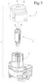
figure 3 is an axonometric view of the switch of the invention; -
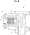
figure 4 is a longitudinal sectional view of the switch of the previous figure; and -
figure 5 is an exploded view of the switch of the invention. - With reference to the above-mentioned figures,
reference numeral 1 indicates a switch according to the invention. - The
switch 1 proposed is especially, but not exclusively, intended to be mounted on a motor vehicle such as, for example, a motorcycle. - The
switch 1 comprises an outer containing and protectingbody 2 that houses arotatable lock cylinder 3, adapted to receive the ignition key and rotatable at least between a shut-off position and an ignition position and preferably also in further operative positions, in particular a parking position and a locking position. - The
outer body 2 is substantially axisymmetric in shape, at least in a main portion thereof and is hollow, so as to house thecylinder 3 and other mechanical components for switching. - The
outer body 2 comprises a front portion including a flatannular wall 20, which is substantially transversal with respect to the main extension axis of the body itself, in which ahole 21 is centrally obtained which allows the access of the key to thecylinder 3, i.e. more precisely to theinsertion hole 31. - The
cylinder 3 in practice defines an ignition "lock" such as those of the prior art, allowing the switching between ignition, shut-off and other operative positions, obtained through the insertion of the key, the thrust and the rotation of thecylinder 3. - In other words, also the
cylinder 3 according to the invention can be axially withdrawn following the user's thrust, and the translation thereof is subject to the action of an elastic contrast means such as, for example, a spring, which brings thecylinder 3 into the initial position. - In detail, the
cylinder 3 is inserted with the possibility to rotate with respect to a central longitudinal axis and to translate with respect to the same axis, in a cylindrical seat obtained in an inner retaining body 4 (shown infigures 4 and5 ), preferably made of metal material, also contained in the inner volume of the protectingbody 3. - The
switch 1 further includes anantenna 5 connected to an electronic immobiliser, adapted to transmit to the control unit of the motor vehicle engine ignition enable/disable signals. - The
antenna 5 is used for communication with a transceiver associated with the ignition key. - In particular, the transceiver may be a transponder (e.g. of the Rfid type) integrated into the key or into a remote control associated with the key. According to an important aspect of the invention, the
antenna 5 is located in theouter body 2. - The
antenna 5 of the proposed switch is connected, e.g. through electrical cables, to a control logic unit of the electronic immobiliser (or ICU, Immobiliser Control Unit). - Such control unit 10 is configured to transmit to the control unit of the vehicle (or ECU, or Engine Control Unit) the vehicle engine ignition enable/disable signals.
- Apart from the peculiar features of the switch disclosed in the present description, the electronic immobiliser can have the features and functions of known immobilisers.
- Preferably, the
antenna 5 is incorporated in theouter body 2 of theswitch 1 and, even more preferably, it is co-moulded to theouter body 2. - For example, through co-moulding, or another manufacturing method, a seat 51 (indicated in
figure 4 ) is defined on the outer surface of thecontainment body 1 in which theantenna 5 is located which is thus separated from the inner volume of thebody 2 in which thecylinder 3 and the innerretaining body 4 of thecylinder 3 itself are located. - Already from this initial explanation, it can be understood that the
antenna 5 is separated and distanced from the inner metal elements of the switch, especially from theinner body 4 in which thecylinder 3 is inserted and therefore does not undergo any interferences that could have a negative effect on its transmission properties. - This circumstance allows the
switch 1 of the invention to be configured so as to eliminate the front recess or depression that was present in the prior art, bringing thefront surface 32 of thecylinder 3, in which theinlet hole 31 for the key is obtained, flush with an outer surface of the frontannular wall 20 of theouter body 2. - In this way, the
switch 1 of the invention does not feature the recess present in the prior art which facilitated the entry of stones or chips that could get caught between thecylinder 3 and the body. - Therefore, the invention completely overcomes the limits of the prior art. The
antenna 5 preferably has an annular shape, at least in a main portion thereof; in this case, theantenna 5 can be arranged so as to at least partially surround a section of theouter body 2. - As can be seen in the appended figures, the
antenna 5 is preferably arranged in a front end portion of theouter body 2, i.e. in proximity to or at the free end of theswitch 1.
Claims (5)
- A switch (1) for motor vehicles, comprising an outer containing and protecting body (2) housing a lock cylinder (3), adapted to receive an ignition key and rotatable through several operative positions by means of the rotation of said key; and at least one antenna (5) connectable to an electronic immobiliser, adapted to transmit to a control unit of the motor vehicle the motor vehicle engine ignition enable/disable signals; said antenna (5) being located in said outer body (2);
wherein the antenna (5) includes at least one part of annular shape; characterized in that the antenna (5) is located in a seat (51) defined on the outer surface of the outer body (2) and is separated by an inner volume defined by the body itself (2); the outer body (2) comprising a front portion, which includes an annular wall (20) wherein a hole (21) allowing the access of the key to said cylinder (3) is obtained, the cylinder having a front surface (32) wherein is obtained an opening (31) for the insertion of the key which is substantially flush with a surface of said annular wall (20). - The switch (1) according to the preceding claim, wherein said antenna (5) is incorporated in the outer body (2).
- The switch (1) according to the preceding claim, wherein the antenna (5) is co-moulded to the outer body (2).
- The switch (1) according to at least one of the preceding claims, wherein the antenna (5) is located in a front end portion of the outer body (2).
- A motor vehicle comprising: an electronic immobiliser provided with a control logic unit configured to transmit to a control unit of the vehicle the vehicle engine ignition enable/disable signals; and a switch (1) according to at least one of the preceding claims, wherein the antenna (5) is connected to said immobiliser control logic unit.
Applications Claiming Priority (1)
| Application Number | Priority Date | Filing Date | Title |
|---|---|---|---|
| IT102018000005348A IT201800005348A1 (en) | 2018-05-14 | 2018-05-14 | Improved commutator. |
Publications (2)
| Publication Number | Publication Date |
|---|---|
| EP3569454A1 EP3569454A1 (en) | 2019-11-20 |
| EP3569454B1 true EP3569454B1 (en) | 2023-04-19 |
Family
ID=63080330
Family Applications (1)
| Application Number | Title | Priority Date | Filing Date |
|---|---|---|---|
| EP19171695.0A Active EP3569454B1 (en) | 2018-05-14 | 2019-04-29 | Ignition switch for motor vehicles |
Country Status (4)
| Country | Link |
|---|---|
| US (1) | US10913424B2 (en) |
| EP (1) | EP3569454B1 (en) |
| IT (1) | IT201800005348A1 (en) |
| PT (1) | PT3569454T (en) |
Family Cites Families (9)
| Publication number | Priority date | Publication date | Assignee | Title |
|---|---|---|---|---|
| US5632168A (en) * | 1994-04-07 | 1997-05-27 | Honda Lock Mfg. Co., Ltd. | Key lock device |
| JP2624187B2 (en) * | 1994-08-24 | 1997-06-25 | 日産自動車株式会社 | Key cylinder device for automobile |
| JPH09100666A (en) * | 1995-10-05 | 1997-04-15 | Tokai Rika Co Ltd | Key cylinder |
| JPH10244853A (en) * | 1997-03-07 | 1998-09-14 | Tokai Rika Co Ltd | Immobilizer system and vehicle |
| FR2780361B1 (en) * | 1998-06-26 | 2000-09-15 | Valeo Electronique | TOP COLUMN SET WITH INTEGRATED ANTI-THEFT |
| JP2004217146A (en) * | 2003-01-17 | 2004-08-05 | Moric Co Ltd | Case structure of immobilizer |
| JP4625724B2 (en) * | 2005-06-28 | 2011-02-02 | 株式会社ホンダロック | Vehicle anti-theft device |
| JP4641232B2 (en) * | 2005-09-14 | 2011-03-02 | 本田技研工業株式会社 | Vehicle antenna device |
| US20070284943A1 (en) * | 2006-03-20 | 2007-12-13 | John Meeks | RF-immobilizer and contactless ignition for a motor vehicle |
-
2018
- 2018-05-14 IT IT102018000005348A patent/IT201800005348A1/en unknown
-
2019
- 2019-04-29 PT PT191716950T patent/PT3569454T/en unknown
- 2019-04-29 EP EP19171695.0A patent/EP3569454B1/en active Active
- 2019-05-10 US US16/408,762 patent/US10913424B2/en active Active
Also Published As
| Publication number | Publication date |
|---|---|
| US20190344752A1 (en) | 2019-11-14 |
| US10913424B2 (en) | 2021-02-09 |
| IT201800005348A1 (en) | 2019-11-14 |
| EP3569454A1 (en) | 2019-11-20 |
| PT3569454T (en) | 2023-05-18 |
Similar Documents
| Publication | Publication Date | Title |
|---|---|---|
| US8266936B2 (en) | Lock-actuating key with improved impact resistance | |
| US20070220936A1 (en) | Key unit | |
| US9260892B2 (en) | Handle having a retaining element, the same having an attachment means which remains entirely inside a moving part | |
| US8695389B2 (en) | Mechanical module for a vehicle key and a key provided with such a module | |
| US4425770A (en) | Steering lock assembly | |
| JP5755880B2 (en) | A pivotable key to actuate the lock with enhanced position lock function | |
| US9682597B1 (en) | Wheel with interchangeable caps | |
| US11207915B1 (en) | Wheel with interchangeable caps | |
| US3702550A (en) | Steering lock device | |
| CN1326728C (en) | Attached steering locking device of operating button for vehicle use | |
| EP3569454B1 (en) | Ignition switch for motor vehicles | |
| AU1698592A (en) | Assembly of mouthpiece, stopper and lock for shutting off a pipe mouth | |
| AU605033B2 (en) | Steering locking apparatus | |
| US8091946B2 (en) | Screwless visor mount assembly | |
| WO2006118730A1 (en) | Coaxial cable port security device and method of use thereof | |
| DE102006031699A1 (en) | Electronic key switch for use with an automobile electronic control system has a two component injection moulded body | |
| JP6042460B2 (en) | Key cylinder device | |
| US11933080B2 (en) | Closing system for a door or hatch of a motor vehicle, door or hatch of a motor vehicle, motor vehicle | |
| US7208849B2 (en) | Detachable transmission shift lever arrangement | |
| JP4573662B2 (en) | Ignition switch device | |
| EP3048221B1 (en) | Handles | |
| KR101724455B1 (en) | Anti-theft antenna | |
| US20020104344A1 (en) | Lock mechanism for deterring access | |
| EP3305607B1 (en) | Steering column lock | |
| CN109216091B (en) | Vehicle ignition system |
Legal Events
| Date | Code | Title | Description |
|---|---|---|---|
| PUAI | Public reference made under article 153(3) epc to a published international application that has entered the european phase |
Free format text: ORIGINAL CODE: 0009012 |
|
| STAA | Information on the status of an ep patent application or granted ep patent |
Free format text: STATUS: THE APPLICATION HAS BEEN PUBLISHED |
|
| AK | Designated contracting states |
Kind code of ref document: A1 Designated state(s): AL AT BE BG CH CY CZ DE DK EE ES FI FR GB GR HR HU IE IS IT LI LT LU LV MC MK MT NL NO PL PT RO RS SE SI SK SM TR |
|
| AX | Request for extension of the european patent |
Extension state: BA ME |
|
| RIN1 | Information on inventor provided before grant (corrected) |
Inventor name: BELPANNO, EMANUELE Inventor name: TESTA, GIUSEPPE |
|
| STAA | Information on the status of an ep patent application or granted ep patent |
Free format text: STATUS: REQUEST FOR EXAMINATION WAS MADE |
|
| 17P | Request for examination filed |
Effective date: 20200901 |
|
| RBV | Designated contracting states (corrected) |
Designated state(s): AL AT BE BG CH CY CZ DE DK EE ES FI FR GB GR HR HU IE IS IT LI LT LU LV MC MK MT NL NO PL PT RO RS SE SI SK SM TR |
|
| RAP3 | Party data changed (applicant data changed or rights of an application transferred) |
Owner name: CEV LAB S.R.L. |
|
| GRAP | Despatch of communication of intention to grant a patent |
Free format text: ORIGINAL CODE: EPIDOSNIGR1 |
|
| STAA | Information on the status of an ep patent application or granted ep patent |
Free format text: STATUS: GRANT OF PATENT IS INTENDED |
|
| INTG | Intention to grant announced |
Effective date: 20221111 |
|
| GRAS | Grant fee paid |
Free format text: ORIGINAL CODE: EPIDOSNIGR3 |
|
| GRAA | (expected) grant |
Free format text: ORIGINAL CODE: 0009210 |
|
| STAA | Information on the status of an ep patent application or granted ep patent |
Free format text: STATUS: THE PATENT HAS BEEN GRANTED |
|
| AK | Designated contracting states |
Kind code of ref document: B1 Designated state(s): AL AT BE BG CH CY CZ DE DK EE ES FI FR GB GR HR HU IE IS IT LI LT LU LV MC MK MT NL NO PL PT RO RS SE SI SK SM TR |
|
| REG | Reference to a national code |
Ref country code: GB Ref legal event code: FG4D |
|
| REG | Reference to a national code |
Ref country code: DE Ref legal event code: R096 Ref document number: 602019027613 Country of ref document: DE |
|
| REG | Reference to a national code |
Ref country code: CH Ref legal event code: EP |
|
| REG | Reference to a national code |
Ref country code: IE Ref legal event code: FG4D |
|
| REG | Reference to a national code |
Ref country code: AT Ref legal event code: REF Ref document number: 1560970 Country of ref document: AT Kind code of ref document: T Effective date: 20230515 |
|
| REG | Reference to a national code |
Ref country code: PT Ref legal event code: SC4A Ref document number: 3569454 Country of ref document: PT Date of ref document: 20230518 Kind code of ref document: T Free format text: AVAILABILITY OF NATIONAL TRANSLATION Effective date: 20230512 |
|
| P01 | Opt-out of the competence of the unified patent court (upc) registered |
Effective date: 20230601 |
|
| REG | Reference to a national code |
Ref country code: LT Ref legal event code: MG9D |
|
| REG | Reference to a national code |
Ref country code: NL Ref legal event code: MP Effective date: 20230419 |
|
| PG25 | Lapsed in a contracting state [announced via postgrant information from national office to epo] |
Ref country code: NL Free format text: LAPSE BECAUSE OF FAILURE TO SUBMIT A TRANSLATION OF THE DESCRIPTION OR TO PAY THE FEE WITHIN THE PRESCRIBED TIME-LIMIT Effective date: 20230419 |
|
| PG25 | Lapsed in a contracting state [announced via postgrant information from national office to epo] |
Ref country code: SE Free format text: LAPSE BECAUSE OF FAILURE TO SUBMIT A TRANSLATION OF THE DESCRIPTION OR TO PAY THE FEE WITHIN THE PRESCRIBED TIME-LIMIT Effective date: 20230419 Ref country code: NO Free format text: LAPSE BECAUSE OF FAILURE TO SUBMIT A TRANSLATION OF THE DESCRIPTION OR TO PAY THE FEE WITHIN THE PRESCRIBED TIME-LIMIT Effective date: 20230719 Ref country code: ES Free format text: LAPSE BECAUSE OF FAILURE TO SUBMIT A TRANSLATION OF THE DESCRIPTION OR TO PAY THE FEE WITHIN THE PRESCRIBED TIME-LIMIT Effective date: 20230419 |
|
| PG25 | Lapsed in a contracting state [announced via postgrant information from national office to epo] |
Ref country code: RS Free format text: LAPSE BECAUSE OF FAILURE TO SUBMIT A TRANSLATION OF THE DESCRIPTION OR TO PAY THE FEE WITHIN THE PRESCRIBED TIME-LIMIT Effective date: 20230419 Ref country code: PL Free format text: LAPSE BECAUSE OF FAILURE TO SUBMIT A TRANSLATION OF THE DESCRIPTION OR TO PAY THE FEE WITHIN THE PRESCRIBED TIME-LIMIT Effective date: 20230419 Ref country code: LV Free format text: LAPSE BECAUSE OF FAILURE TO SUBMIT A TRANSLATION OF THE DESCRIPTION OR TO PAY THE FEE WITHIN THE PRESCRIBED TIME-LIMIT Effective date: 20230419 Ref country code: LT Free format text: LAPSE BECAUSE OF FAILURE TO SUBMIT A TRANSLATION OF THE DESCRIPTION OR TO PAY THE FEE WITHIN THE PRESCRIBED TIME-LIMIT Effective date: 20230419 Ref country code: IS Free format text: LAPSE BECAUSE OF FAILURE TO SUBMIT A TRANSLATION OF THE DESCRIPTION OR TO PAY THE FEE WITHIN THE PRESCRIBED TIME-LIMIT Effective date: 20230819 Ref country code: HR Free format text: LAPSE BECAUSE OF FAILURE TO SUBMIT A TRANSLATION OF THE DESCRIPTION OR TO PAY THE FEE WITHIN THE PRESCRIBED TIME-LIMIT Effective date: 20230419 Ref country code: GR Free format text: LAPSE BECAUSE OF FAILURE TO SUBMIT A TRANSLATION OF THE DESCRIPTION OR TO PAY THE FEE WITHIN THE PRESCRIBED TIME-LIMIT Effective date: 20230720 Ref country code: AL Free format text: LAPSE BECAUSE OF FAILURE TO SUBMIT A TRANSLATION OF THE DESCRIPTION OR TO PAY THE FEE WITHIN THE PRESCRIBED TIME-LIMIT Effective date: 20230419 |
|
| REG | Reference to a national code |
Ref country code: CH Ref legal event code: PL |
|
| REG | Reference to a national code |
Ref country code: AT Ref legal event code: UEP Ref document number: 1560970 Country of ref document: AT Kind code of ref document: T Effective date: 20230419 |
|
| PG25 | Lapsed in a contracting state [announced via postgrant information from national office to epo] |
Ref country code: LU Free format text: LAPSE BECAUSE OF NON-PAYMENT OF DUE FEES Effective date: 20230429 Ref country code: FI Free format text: LAPSE BECAUSE OF FAILURE TO SUBMIT A TRANSLATION OF THE DESCRIPTION OR TO PAY THE FEE WITHIN THE PRESCRIBED TIME-LIMIT Effective date: 20230419 |
|
| REG | Reference to a national code |
Ref country code: BE Ref legal event code: MM Effective date: 20230430 |
|
| PG25 | Lapsed in a contracting state [announced via postgrant information from national office to epo] |
Ref country code: SK Free format text: LAPSE BECAUSE OF FAILURE TO SUBMIT A TRANSLATION OF THE DESCRIPTION OR TO PAY THE FEE WITHIN THE PRESCRIBED TIME-LIMIT Effective date: 20230419 |
|
| PG25 | Lapsed in a contracting state [announced via postgrant information from national office to epo] |
Ref country code: MC Free format text: LAPSE BECAUSE OF FAILURE TO SUBMIT A TRANSLATION OF THE DESCRIPTION OR TO PAY THE FEE WITHIN THE PRESCRIBED TIME-LIMIT Effective date: 20230419 |
|
| REG | Reference to a national code |
Ref country code: DE Ref legal event code: R097 Ref document number: 602019027613 Country of ref document: DE |
|
| PG25 | Lapsed in a contracting state [announced via postgrant information from national office to epo] |
Ref country code: SM Free format text: LAPSE BECAUSE OF FAILURE TO SUBMIT A TRANSLATION OF THE DESCRIPTION OR TO PAY THE FEE WITHIN THE PRESCRIBED TIME-LIMIT Effective date: 20230419 Ref country code: SK Free format text: LAPSE BECAUSE OF FAILURE TO SUBMIT A TRANSLATION OF THE DESCRIPTION OR TO PAY THE FEE WITHIN THE PRESCRIBED TIME-LIMIT Effective date: 20230419 Ref country code: RO Free format text: LAPSE BECAUSE OF FAILURE TO SUBMIT A TRANSLATION OF THE DESCRIPTION OR TO PAY THE FEE WITHIN THE PRESCRIBED TIME-LIMIT Effective date: 20230419 Ref country code: MC Free format text: LAPSE BECAUSE OF FAILURE TO SUBMIT A TRANSLATION OF THE DESCRIPTION OR TO PAY THE FEE WITHIN THE PRESCRIBED TIME-LIMIT Effective date: 20230419 Ref country code: LI Free format text: LAPSE BECAUSE OF NON-PAYMENT OF DUE FEES Effective date: 20230430 Ref country code: EE Free format text: LAPSE BECAUSE OF FAILURE TO SUBMIT A TRANSLATION OF THE DESCRIPTION OR TO PAY THE FEE WITHIN THE PRESCRIBED TIME-LIMIT Effective date: 20230419 Ref country code: DK Free format text: LAPSE BECAUSE OF FAILURE TO SUBMIT A TRANSLATION OF THE DESCRIPTION OR TO PAY THE FEE WITHIN THE PRESCRIBED TIME-LIMIT Effective date: 20230419 Ref country code: CZ Free format text: LAPSE BECAUSE OF FAILURE TO SUBMIT A TRANSLATION OF THE DESCRIPTION OR TO PAY THE FEE WITHIN THE PRESCRIBED TIME-LIMIT Effective date: 20230419 Ref country code: CH Free format text: LAPSE BECAUSE OF NON-PAYMENT OF DUE FEES Effective date: 20230430 |
|
| REG | Reference to a national code |
Ref country code: IE Ref legal event code: MM4A |
|
| PLBE | No opposition filed within time limit |
Free format text: ORIGINAL CODE: 0009261 |
|
| STAA | Information on the status of an ep patent application or granted ep patent |
Free format text: STATUS: NO OPPOSITION FILED WITHIN TIME LIMIT |
|
| PG25 | Lapsed in a contracting state [announced via postgrant information from national office to epo] |
Ref country code: BE Free format text: LAPSE BECAUSE OF NON-PAYMENT OF DUE FEES Effective date: 20230430 |
|
| 26N | No opposition filed |
Effective date: 20240122 |
|
| GBPC | Gb: european patent ceased through non-payment of renewal fee |
Effective date: 20230719 |
|
| PG25 | Lapsed in a contracting state [announced via postgrant information from national office to epo] |
Ref country code: IE Free format text: LAPSE BECAUSE OF NON-PAYMENT OF DUE FEES Effective date: 20230429 |
|
| PG25 | Lapsed in a contracting state [announced via postgrant information from national office to epo] |
Ref country code: IE Free format text: LAPSE BECAUSE OF NON-PAYMENT OF DUE FEES Effective date: 20230429 Ref country code: GB Free format text: LAPSE BECAUSE OF NON-PAYMENT OF DUE FEES Effective date: 20230719 |
|
| PG25 | Lapsed in a contracting state [announced via postgrant information from national office to epo] |
Ref country code: SI Free format text: LAPSE BECAUSE OF FAILURE TO SUBMIT A TRANSLATION OF THE DESCRIPTION OR TO PAY THE FEE WITHIN THE PRESCRIBED TIME-LIMIT Effective date: 20230419 |
|
| PG25 | Lapsed in a contracting state [announced via postgrant information from national office to epo] |
Ref country code: SI Free format text: LAPSE BECAUSE OF FAILURE TO SUBMIT A TRANSLATION OF THE DESCRIPTION OR TO PAY THE FEE WITHIN THE PRESCRIBED TIME-LIMIT Effective date: 20230419 |
|
| PG25 | Lapsed in a contracting state [announced via postgrant information from national office to epo] |
Ref country code: BG Free format text: LAPSE BECAUSE OF FAILURE TO SUBMIT A TRANSLATION OF THE DESCRIPTION OR TO PAY THE FEE WITHIN THE PRESCRIBED TIME-LIMIT Effective date: 20230419 |
|
| PG25 | Lapsed in a contracting state [announced via postgrant information from national office to epo] |
Ref country code: BG Free format text: LAPSE BECAUSE OF FAILURE TO SUBMIT A TRANSLATION OF THE DESCRIPTION OR TO PAY THE FEE WITHIN THE PRESCRIBED TIME-LIMIT Effective date: 20230419 |
|
| PGFP | Annual fee paid to national office [announced via postgrant information from national office to epo] |
Ref country code: DE Payment date: 20250428 Year of fee payment: 7 |
|
| PGFP | Annual fee paid to national office [announced via postgrant information from national office to epo] |
Ref country code: IT Payment date: 20250408 Year of fee payment: 7 |
|
| PGFP | Annual fee paid to national office [announced via postgrant information from national office to epo] |
Ref country code: PT Payment date: 20250409 Year of fee payment: 7 |
|
| PGFP | Annual fee paid to national office [announced via postgrant information from national office to epo] |
Ref country code: FR Payment date: 20250424 Year of fee payment: 7 |
|
| PGFP | Annual fee paid to national office [announced via postgrant information from national office to epo] |
Ref country code: AT Payment date: 20250417 Year of fee payment: 7 |
|
| PG25 | Lapsed in a contracting state [announced via postgrant information from national office to epo] |
Ref country code: CY Free format text: LAPSE BECAUSE OF FAILURE TO SUBMIT A TRANSLATION OF THE DESCRIPTION OR TO PAY THE FEE WITHIN THE PRESCRIBED TIME-LIMIT; INVALID AB INITIO Effective date: 20190429 |
|
| PG25 | Lapsed in a contracting state [announced via postgrant information from national office to epo] |
Ref country code: HU Free format text: LAPSE BECAUSE OF FAILURE TO SUBMIT A TRANSLATION OF THE DESCRIPTION OR TO PAY THE FEE WITHIN THE PRESCRIBED TIME-LIMIT; INVALID AB INITIO Effective date: 20190429 |
|
| PG25 | Lapsed in a contracting state [announced via postgrant information from national office to epo] |
Ref country code: TR Free format text: LAPSE BECAUSE OF FAILURE TO SUBMIT A TRANSLATION OF THE DESCRIPTION OR TO PAY THE FEE WITHIN THE PRESCRIBED TIME-LIMIT Effective date: 20230419 |