EP3569437A1 - Display device - Google Patents
Display device Download PDFInfo
- Publication number
- EP3569437A1 EP3569437A1 EP18754599.1A EP18754599A EP3569437A1 EP 3569437 A1 EP3569437 A1 EP 3569437A1 EP 18754599 A EP18754599 A EP 18754599A EP 3569437 A1 EP3569437 A1 EP 3569437A1
- Authority
- EP
- European Patent Office
- Prior art keywords
- speed
- display
- moving body
- frame member
- driver
- Prior art date
- Legal status (The legal status is an assumption and is not a legal conclusion. Google has not performed a legal analysis and makes no representation as to the accuracy of the status listed.)
- Withdrawn
Links
Images


Classifications
-
- B—PERFORMING OPERATIONS; TRANSPORTING
- B60—VEHICLES IN GENERAL
- B60K—ARRANGEMENT OR MOUNTING OF PROPULSION UNITS OR OF TRANSMISSIONS IN VEHICLES; ARRANGEMENT OR MOUNTING OF PLURAL DIVERSE PRIME-MOVERS IN VEHICLES; AUXILIARY DRIVES FOR VEHICLES; INSTRUMENTATION OR DASHBOARDS FOR VEHICLES; ARRANGEMENTS IN CONNECTION WITH COOLING, AIR INTAKE, GAS EXHAUST OR FUEL SUPPLY OF PROPULSION UNITS IN VEHICLES
- B60K35/00—Instruments specially adapted for vehicles; Arrangement of instruments in or on vehicles
- B60K35/60—Instruments characterised by their location or relative disposition in or on vehicles
-
- B—PERFORMING OPERATIONS; TRANSPORTING
- B60—VEHICLES IN GENERAL
- B60Q—ARRANGEMENT OF SIGNALLING OR LIGHTING DEVICES, THE MOUNTING OR SUPPORTING THEREOF OR CIRCUITS THEREFOR, FOR VEHICLES IN GENERAL
- B60Q1/00—Arrangement of optical signalling or lighting devices, the mounting or supporting thereof or circuits therefor
- B60Q1/26—Arrangement of optical signalling or lighting devices, the mounting or supporting thereof or circuits therefor the devices being primarily intended to indicate the vehicle, or parts thereof, or to give signals, to other traffic
- B60Q1/50—Arrangement of optical signalling or lighting devices, the mounting or supporting thereof or circuits therefor the devices being primarily intended to indicate the vehicle, or parts thereof, or to give signals, to other traffic for indicating other intentions or conditions, e.g. request for waiting or overtaking
- B60Q1/54—Arrangement of optical signalling or lighting devices, the mounting or supporting thereof or circuits therefor the devices being primarily intended to indicate the vehicle, or parts thereof, or to give signals, to other traffic for indicating other intentions or conditions, e.g. request for waiting or overtaking for indicating speed outside of the vehicle
-
- B—PERFORMING OPERATIONS; TRANSPORTING
- B60—VEHICLES IN GENERAL
- B60K—ARRANGEMENT OR MOUNTING OF PROPULSION UNITS OR OF TRANSMISSIONS IN VEHICLES; ARRANGEMENT OR MOUNTING OF PLURAL DIVERSE PRIME-MOVERS IN VEHICLES; AUXILIARY DRIVES FOR VEHICLES; INSTRUMENTATION OR DASHBOARDS FOR VEHICLES; ARRANGEMENTS IN CONNECTION WITH COOLING, AIR INTAKE, GAS EXHAUST OR FUEL SUPPLY OF PROPULSION UNITS IN VEHICLES
- B60K31/00—Vehicle fittings, acting on a single sub-unit only, for automatically controlling vehicle speed, i.e. preventing speed from exceeding an arbitrarily established velocity or maintaining speed at a particular velocity, as selected by the vehicle operator
-
- B—PERFORMING OPERATIONS; TRANSPORTING
- B60—VEHICLES IN GENERAL
- B60K—ARRANGEMENT OR MOUNTING OF PROPULSION UNITS OR OF TRANSMISSIONS IN VEHICLES; ARRANGEMENT OR MOUNTING OF PLURAL DIVERSE PRIME-MOVERS IN VEHICLES; AUXILIARY DRIVES FOR VEHICLES; INSTRUMENTATION OR DASHBOARDS FOR VEHICLES; ARRANGEMENTS IN CONNECTION WITH COOLING, AIR INTAKE, GAS EXHAUST OR FUEL SUPPLY OF PROPULSION UNITS IN VEHICLES
- B60K35/00—Instruments specially adapted for vehicles; Arrangement of instruments in or on vehicles
- B60K35/20—Output arrangements, i.e. from vehicle to user, associated with vehicle functions or specially adapted therefor
- B60K35/21—Output arrangements, i.e. from vehicle to user, associated with vehicle functions or specially adapted therefor using visual output, e.g. blinking lights or matrix displays
- B60K35/213—Virtual instruments
-
- B—PERFORMING OPERATIONS; TRANSPORTING
- B60—VEHICLES IN GENERAL
- B60K—ARRANGEMENT OR MOUNTING OF PROPULSION UNITS OR OF TRANSMISSIONS IN VEHICLES; ARRANGEMENT OR MOUNTING OF PLURAL DIVERSE PRIME-MOVERS IN VEHICLES; AUXILIARY DRIVES FOR VEHICLES; INSTRUMENTATION OR DASHBOARDS FOR VEHICLES; ARRANGEMENTS IN CONNECTION WITH COOLING, AIR INTAKE, GAS EXHAUST OR FUEL SUPPLY OF PROPULSION UNITS IN VEHICLES
- B60K35/00—Instruments specially adapted for vehicles; Arrangement of instruments in or on vehicles
- B60K35/20—Output arrangements, i.e. from vehicle to user, associated with vehicle functions or specially adapted therefor
- B60K35/21—Output arrangements, i.e. from vehicle to user, associated with vehicle functions or specially adapted therefor using visual output, e.g. blinking lights or matrix displays
- B60K35/22—Display screens
-
- B—PERFORMING OPERATIONS; TRANSPORTING
- B60—VEHICLES IN GENERAL
- B60K—ARRANGEMENT OR MOUNTING OF PROPULSION UNITS OR OF TRANSMISSIONS IN VEHICLES; ARRANGEMENT OR MOUNTING OF PLURAL DIVERSE PRIME-MOVERS IN VEHICLES; AUXILIARY DRIVES FOR VEHICLES; INSTRUMENTATION OR DASHBOARDS FOR VEHICLES; ARRANGEMENTS IN CONNECTION WITH COOLING, AIR INTAKE, GAS EXHAUST OR FUEL SUPPLY OF PROPULSION UNITS IN VEHICLES
- B60K35/00—Instruments specially adapted for vehicles; Arrangement of instruments in or on vehicles
- B60K35/20—Output arrangements, i.e. from vehicle to user, associated with vehicle functions or specially adapted therefor
- B60K35/28—Output arrangements, i.e. from vehicle to user, associated with vehicle functions or specially adapted therefor characterised by the type of the output information, e.g. video entertainment or vehicle dynamics information; characterised by the purpose of the output information, e.g. for attracting the attention of the driver
-
- B—PERFORMING OPERATIONS; TRANSPORTING
- B60—VEHICLES IN GENERAL
- B60K—ARRANGEMENT OR MOUNTING OF PROPULSION UNITS OR OF TRANSMISSIONS IN VEHICLES; ARRANGEMENT OR MOUNTING OF PLURAL DIVERSE PRIME-MOVERS IN VEHICLES; AUXILIARY DRIVES FOR VEHICLES; INSTRUMENTATION OR DASHBOARDS FOR VEHICLES; ARRANGEMENTS IN CONNECTION WITH COOLING, AIR INTAKE, GAS EXHAUST OR FUEL SUPPLY OF PROPULSION UNITS IN VEHICLES
- B60K35/00—Instruments specially adapted for vehicles; Arrangement of instruments in or on vehicles
- B60K35/20—Output arrangements, i.e. from vehicle to user, associated with vehicle functions or specially adapted therefor
- B60K35/29—Instruments characterised by the way in which information is handled, e.g. showing information on plural displays or prioritising information according to driving conditions
-
- B—PERFORMING OPERATIONS; TRANSPORTING
- B60—VEHICLES IN GENERAL
- B60K—ARRANGEMENT OR MOUNTING OF PROPULSION UNITS OR OF TRANSMISSIONS IN VEHICLES; ARRANGEMENT OR MOUNTING OF PLURAL DIVERSE PRIME-MOVERS IN VEHICLES; AUXILIARY DRIVES FOR VEHICLES; INSTRUMENTATION OR DASHBOARDS FOR VEHICLES; ARRANGEMENTS IN CONNECTION WITH COOLING, AIR INTAKE, GAS EXHAUST OR FUEL SUPPLY OF PROPULSION UNITS IN VEHICLES
- B60K35/00—Instruments specially adapted for vehicles; Arrangement of instruments in or on vehicles
- B60K35/80—Arrangements for controlling instruments
- B60K35/81—Arrangements for controlling instruments for controlling displays
-
- G—PHYSICS
- G01—MEASURING; TESTING
- G01D—MEASURING NOT SPECIALLY ADAPTED FOR A SPECIFIC VARIABLE; ARRANGEMENTS FOR MEASURING TWO OR MORE VARIABLES NOT COVERED IN A SINGLE OTHER SUBCLASS; TARIFF METERING APPARATUS; MEASURING OR TESTING NOT OTHERWISE PROVIDED FOR
- G01D7/00—Indicating measured values
-
- G—PHYSICS
- G06—COMPUTING OR CALCULATING; COUNTING
- G06V—IMAGE OR VIDEO RECOGNITION OR UNDERSTANDING
- G06V20/00—Scenes; Scene-specific elements
- G06V20/50—Context or environment of the image
- G06V20/56—Context or environment of the image exterior to a vehicle by using sensors mounted on the vehicle
- G06V20/58—Recognition of moving objects or obstacles, e.g. vehicles or pedestrians; Recognition of traffic objects, e.g. traffic signs, traffic lights or roads
- G06V20/582—Recognition of moving objects or obstacles, e.g. vehicles or pedestrians; Recognition of traffic objects, e.g. traffic signs, traffic lights or roads of traffic signs
-
- G—PHYSICS
- G08—SIGNALLING
- G08G—TRAFFIC CONTROL SYSTEMS
- G08G1/00—Traffic control systems for road vehicles
- G08G1/09—Arrangements for giving variable traffic instructions
- G08G1/0962—Arrangements for giving variable traffic instructions having an indicator mounted inside the vehicle, e.g. giving voice messages
- G08G1/0967—Systems involving transmission of highway information, e.g. weather, speed limits
- G08G1/096708—Systems involving transmission of highway information, e.g. weather, speed limits where the received information might be used to generate an automatic action on the vehicle control
- G08G1/096716—Systems involving transmission of highway information, e.g. weather, speed limits where the received information might be used to generate an automatic action on the vehicle control where the received information does not generate an automatic action on the vehicle control
-
- G—PHYSICS
- G08—SIGNALLING
- G08G—TRAFFIC CONTROL SYSTEMS
- G08G1/00—Traffic control systems for road vehicles
- G08G1/09—Arrangements for giving variable traffic instructions
- G08G1/0962—Arrangements for giving variable traffic instructions having an indicator mounted inside the vehicle, e.g. giving voice messages
- G08G1/0967—Systems involving transmission of highway information, e.g. weather, speed limits
- G08G1/096766—Systems involving transmission of highway information, e.g. weather, speed limits where the system is characterised by the origin of the information transmission
- G08G1/096783—Systems involving transmission of highway information, e.g. weather, speed limits where the system is characterised by the origin of the information transmission where the origin of the information is a roadside individual element
-
- G—PHYSICS
- G09—EDUCATION; CRYPTOGRAPHY; DISPLAY; ADVERTISING; SEALS
- G09F—DISPLAYING; ADVERTISING; SIGNS; LABELS OR NAME-PLATES; SEALS
- G09F9/00—Indicating arrangements for variable information in which the information is built-up on a support by selection or combination of individual elements
-
- G—PHYSICS
- G09—EDUCATION; CRYPTOGRAPHY; DISPLAY; ADVERTISING; SEALS
- G09G—ARRANGEMENTS OR CIRCUITS FOR CONTROL OF INDICATING DEVICES USING STATIC MEANS TO PRESENT VARIABLE INFORMATION
- G09G5/00—Control arrangements or circuits for visual indicators common to cathode-ray tube indicators and other visual indicators
- G09G5/36—Control arrangements or circuits for visual indicators common to cathode-ray tube indicators and other visual indicators characterised by the display of a graphic pattern, e.g. using an all-points-addressable [APA] memory
-
- B—PERFORMING OPERATIONS; TRANSPORTING
- B60—VEHICLES IN GENERAL
- B60K—ARRANGEMENT OR MOUNTING OF PROPULSION UNITS OR OF TRANSMISSIONS IN VEHICLES; ARRANGEMENT OR MOUNTING OF PLURAL DIVERSE PRIME-MOVERS IN VEHICLES; AUXILIARY DRIVES FOR VEHICLES; INSTRUMENTATION OR DASHBOARDS FOR VEHICLES; ARRANGEMENTS IN CONNECTION WITH COOLING, AIR INTAKE, GAS EXHAUST OR FUEL SUPPLY OF PROPULSION UNITS IN VEHICLES
- B60K2360/00—Indexing scheme associated with groups B60K35/00 or B60K37/00 relating to details of instruments or dashboards
- B60K2360/16—Type of output information
- B60K2360/168—Target or limit values
-
- B—PERFORMING OPERATIONS; TRANSPORTING
- B60—VEHICLES IN GENERAL
- B60K—ARRANGEMENT OR MOUNTING OF PROPULSION UNITS OR OF TRANSMISSIONS IN VEHICLES; ARRANGEMENT OR MOUNTING OF PLURAL DIVERSE PRIME-MOVERS IN VEHICLES; AUXILIARY DRIVES FOR VEHICLES; INSTRUMENTATION OR DASHBOARDS FOR VEHICLES; ARRANGEMENTS IN CONNECTION WITH COOLING, AIR INTAKE, GAS EXHAUST OR FUEL SUPPLY OF PROPULSION UNITS IN VEHICLES
- B60K2360/00—Indexing scheme associated with groups B60K35/00 or B60K37/00 relating to details of instruments or dashboards
- B60K2360/16—Type of output information
- B60K2360/178—Warnings
-
- B—PERFORMING OPERATIONS; TRANSPORTING
- B60—VEHICLES IN GENERAL
- B60K—ARRANGEMENT OR MOUNTING OF PROPULSION UNITS OR OF TRANSMISSIONS IN VEHICLES; ARRANGEMENT OR MOUNTING OF PLURAL DIVERSE PRIME-MOVERS IN VEHICLES; AUXILIARY DRIVES FOR VEHICLES; INSTRUMENTATION OR DASHBOARDS FOR VEHICLES; ARRANGEMENTS IN CONNECTION WITH COOLING, AIR INTAKE, GAS EXHAUST OR FUEL SUPPLY OF PROPULSION UNITS IN VEHICLES
- B60K2360/00—Indexing scheme associated with groups B60K35/00 or B60K37/00 relating to details of instruments or dashboards
- B60K2360/18—Information management
- B60K2360/191—Highlight information
-
- B—PERFORMING OPERATIONS; TRANSPORTING
- B60—VEHICLES IN GENERAL
- B60K—ARRANGEMENT OR MOUNTING OF PROPULSION UNITS OR OF TRANSMISSIONS IN VEHICLES; ARRANGEMENT OR MOUNTING OF PLURAL DIVERSE PRIME-MOVERS IN VEHICLES; AUXILIARY DRIVES FOR VEHICLES; INSTRUMENTATION OR DASHBOARDS FOR VEHICLES; ARRANGEMENTS IN CONNECTION WITH COOLING, AIR INTAKE, GAS EXHAUST OR FUEL SUPPLY OF PROPULSION UNITS IN VEHICLES
- B60K2360/00—Indexing scheme associated with groups B60K35/00 or B60K37/00 relating to details of instruments or dashboards
- B60K2360/20—Optical features of instruments
- B60K2360/21—Optical features of instruments using cameras
-
- B—PERFORMING OPERATIONS; TRANSPORTING
- B60—VEHICLES IN GENERAL
- B60K—ARRANGEMENT OR MOUNTING OF PROPULSION UNITS OR OF TRANSMISSIONS IN VEHICLES; ARRANGEMENT OR MOUNTING OF PLURAL DIVERSE PRIME-MOVERS IN VEHICLES; AUXILIARY DRIVES FOR VEHICLES; INSTRUMENTATION OR DASHBOARDS FOR VEHICLES; ARRANGEMENTS IN CONNECTION WITH COOLING, AIR INTAKE, GAS EXHAUST OR FUEL SUPPLY OF PROPULSION UNITS IN VEHICLES
- B60K35/00—Instruments specially adapted for vehicles; Arrangement of instruments in or on vehicles
- B60K35/20—Output arrangements, i.e. from vehicle to user, associated with vehicle functions or specially adapted therefor
- B60K35/21—Output arrangements, i.e. from vehicle to user, associated with vehicle functions or specially adapted therefor using visual output, e.g. blinking lights or matrix displays
- B60K35/215—Output arrangements, i.e. from vehicle to user, associated with vehicle functions or specially adapted therefor using visual output, e.g. blinking lights or matrix displays characterised by the combination of multiple visual outputs, e.g. combined instruments with analogue meters and additional displays
-
- B—PERFORMING OPERATIONS; TRANSPORTING
- B60—VEHICLES IN GENERAL
- B60R—VEHICLES, VEHICLE FITTINGS, OR VEHICLE PARTS, NOT OTHERWISE PROVIDED FOR
- B60R2300/00—Details of viewing arrangements using cameras and displays, specially adapted for use in a vehicle
- B60R2300/20—Details of viewing arrangements using cameras and displays, specially adapted for use in a vehicle characterised by the type of display used
- B60R2300/207—Details of viewing arrangements using cameras and displays, specially adapted for use in a vehicle characterised by the type of display used using multi-purpose displays, e.g. camera image and navigation or video on same display
-
- B—PERFORMING OPERATIONS; TRANSPORTING
- B60—VEHICLES IN GENERAL
- B60R—VEHICLES, VEHICLE FITTINGS, OR VEHICLE PARTS, NOT OTHERWISE PROVIDED FOR
- B60R2300/00—Details of viewing arrangements using cameras and displays, specially adapted for use in a vehicle
- B60R2300/30—Details of viewing arrangements using cameras and displays, specially adapted for use in a vehicle characterised by the type of image processing
- B60R2300/302—Details of viewing arrangements using cameras and displays, specially adapted for use in a vehicle characterised by the type of image processing combining image information with GPS information or vehicle data, e.g. vehicle speed, gyro, steering angle data
Definitions
- the present invention relates to a display device for displaying information such as a speed to a driver of a moving body such as a vehicle.
- a display device (meter device) for displaying information to a driver is provided on a front side of a driver's seat of a moving body such as a vehicle.
- the display device may also display, in addition to a speed of a vehicle (own vehicle speed) at a point of time when the own vehicle speed is displayed, speed information on a speed other than the own vehicle speed.
- Patent Literature 1 proposes a display device for displaying a predetermined recognition speed, in addition to an own vehicle speed.
- Patent Literature 1 Japanese Unexamined Patent Application Publication No. 2010-143407
- an object of the present invention is to provide a display device that enables to appropriately convey each piece of speed information to a driver, based on determination as to whether the speed information is speed information easily recognized by a driver of a moving body.
- a display device is a display device for displaying information relating to at least a moving body to a driver of the moving body.
- the display device includes a display unit for displaying a moving body speed being a speed of the moving body, a first speed that is arbitrarily settable by the driver, and a second speed that is not arbitrarily settable by the driver.
- the display unit displays the first speed and the second speed in ways different from each other.
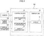
- FIG. 1 is a block diagram of a control system of a display device 100.
- the display device 100 includes a control device 10 and a display unit 20.
- the display device 100 is mounted on an instrument panel (not illustrated), which is disposed on a front side of a driver's seat of a vehicle as a moving body.
- the display device 100 displays various types of information to a driver seated on the driver's seat.
- the embodiment of the present invention describes a vehicle, more specifically, an automobile, as a moving body. The present invention, however, may be applied to a moving body other than a vehicle.
- the control device 10 is constituted by a CPU, a ROM, a RAM, and the like. Further, the control device 10 is electrically connected to a camera 101 for photographing outside of a vehicle, a vehicle speed sensor 102 for measuring an own vehicle speed, and a constant speed driving setting unit 103 for performing setting on constant speed driving control.
- the control device 10 acquires vehicle-outside video information, own vehicle speed information, and constant speed driving setting information, respectively, based on a signal to be transmitted from the pieces of equipment (101 to 103). Further, the control device 10 performs various calculations, based on pieces of information acquired from the pieces of equipment, and transmits a control signal to the display unit 20.
- Constant speed driving control includes control (cruise control) of simply driving a vehicle at a constant speed, and control (active cruise control) of driving a vehicle at a constant speed, when there is a distance equal to or larger than a fixed value with respect to a preceding vehicle.
- a driver can arbitrarily set whether constant speed driving control is performed, and a speed when constant speed driving is performed by using the constant speed driving setting unit 103.
- the "setting speed” means a speed of constant speed driving set by the constant speed driving setting unit 103.
- control device 10 includes, as a functional configuration, a sign recognition unit 11, a setting information acquisition unit 12, and a display control unit 13.
- the sign recognition unit 11 recognizes a limiting speed written on a speed sign, which is installed on the outside of a vehicle, based on vehicle-outside video information acquired from the camera 101.
- the setting information acquisition unit 12 acquires constant speed driving setting information set by the constant speed driving setting unit 103, namely, information indicating whether constant speed driving control is performed, and information on a set setting speed.
- the display control unit 13 controls a display 21 by transmitting a control signal to the display 21 of the display unit 20, which is described later.
- the display unit 20 includes the display 21 having a drawing function.
- the display 21 displays a predetermined content including each piece of speed information, based on a control signal transmitted from the display control unit 13.
- the display 21 is, for example, a liquid crystal display
- the drawing function is a function of displaying an image such as a figure, a character, and a number, which is stored in advance (or given by communication). Details on the display unit 20 are described in the following.
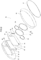
- FIG. 2 is an exploded perspective view of the display unit 20.
- the display unit 20 includes, in addition to the display 21, a base plate 22, a screen 23, a tachometer pointer 24, a water temperature meter pointer 25, a fuel meter pointer 26, a circular frame member 27, a frame member 28 for a tachometer, a frame member 29 for a water temperature meter and a fuel meter, an outer perimeter cover 30, and a surface cover 31.
- the base plate 22 includes an insertion portion 36 for receiving the display 21.
- a surface of the display 21 and a surface of the base plate 22 are located on a same plane.
- the base plate 22 includes a tachometer driving motor 37 for driving the tachometer pointer 24, a water temperature meter driving motor 38 for driving the water temperature meter pointer 25, and a fuel meter driving motor 39 for driving the fuel meter pointer 26.
- a tachometer driving motor 37 for driving the tachometer pointer 24
- a water temperature meter driving motor 38 for driving the water temperature meter pointer 25
- a fuel meter driving motor 39 for driving the fuel meter pointer 26.
- the screen 23 is a member for covering a surface of the display 21 and a surface of the base plate 22.
- a portion of the screen 23 associated with the display 21 is transparent and has light transparency.
- a portion of the screen 23 other than the portion associated with the display 21 is coated black, for example, and does not have light transparency.
- through-holes 40, 41, and 42 are formed in portions of the screen 23 respectively associated with the driving motors 37, 38, and 39. The drive axes of the driving motor 37, 38, and 39 respectively pass through the through-holes 40, 41, and 42.
- a tachometer scale is drawn on a portion of the screen 23 associated with the tachometer pointer 24, a scale for a water temperature meter is drawn on a portion of the screen 23 associated with the water temperature meter pointer 25, and a scale for a fuel meter is drawn on a portion of the screen 23 associated with the fuel meter pointer 26 (also see FIG. 3 ).
- the tachometer pointer 24 is mounted on the drive axis of the tachometer driving motor 37, and designates an engine rotation number at a point of time when measurement is performed. Further, the water temperature meter pointer 25 is mounted on the drive axis of the water temperature meter driving motor 38, and designates a temperature of cooling water at a point of time when measurement is performed. The fuel meter pointer 26 is mounted on the drive axis of the fuel meter driving motor 39, and designates an amount of fuel inside a fuel tank at a point of time when measurement is performed.
- the circular frame member 27 is a circular frame member located at a middle of the display unit 20.
- the circular frame member 27 in the present embodiment is constituted by an annular-shaped base ring 32, and an annular-shaped decorative ring 33 for covering the base ring 32 from above.
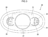
- FIG. 3 is a diagram of the display unit 20 viewed from a driver's seat when the display 21 is in a non-display state. An area surrounded by a broken line in FIG. 3 indicates a display area of the display 21. As illustrated in FIG. 3 , the circular frame member 27 is disposed over the display 21.
- the display 21 has a display area spanning an inner side and an outer side of the circular frame member 27.
- the tachometer frame member 28 is a frame member of an arc shape (circular shape in which a part is missing).
- the tachometer frame member 28 is disposed on a portion of the screen 23 where a tachometer scale is drawn.
- the frame member 29 for a water temperature meter and a fuel meter is a frame member of an arc shape (circular shape in which a part is missing).
- the frame member 29 is disposed on a portion of the screen 23 where a scale of a water temperature meter and a scale of a fuel meter are drawn.
- the tachometer pointer 24, the water temperature meter pointer 25, and the fuel meter pointer 26 are located on the outer side of the display 21.
- the outer perimeter cover 30 is a member for defining an outer perimeter of the display unit 20.
- the surface cover 31 is a member having light transparency, and configured to cover a surface of the screen 23 from outside of the frame members 27 to 29 and the pointers 24 to 26 (from the driver's seat side).
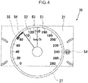
- FIG. 4 is a diagram of the display unit 20, when viewed from a driver's seat side, and illustrates a state that the display 21 displays each piece of speed information.
- the display 21 displays, as speed information, an own vehicle speed being a speed of a vehicle at a point of time when measurement is performed, a setting speed for constant speed driving control, and a limiting speed recognized by the sign recognition unit 11.
- the display 21 displays a speed scale 51, an own vehicle speed pointer 52, a setting speed pointer 53, and a simulated sign 54.
- the speed scale 51 is a scale indicating a speed.
- the speed scale 51 is drawn on the inside of the circular frame member 27 along the circular frame member 27.
- the own vehicle speed pointer 52 is a movable pointer indicating an own vehicle speed.
- the own vehicle speed pointer 52 is located on the inner side of the circular frame member 27, and designates a value of the speed scale 51 associated with the own vehicle speed.
- the own vehicle speed pointer 52 is indicated as an image analogous to a real meter pointer. In this way, in the present embodiment, an own vehicle speed is displayed on the inner side of a circular area surrounded by the circular frame member 27 by the speed scale 51 and the own vehicle pointer 52. In other words, an own vehicle speed is displayed in a way similar to a conventional analog speed meter.
- the setting speed pointer 53 is a fixed pointer indicating a setting speed for constant speed driving control.
- the setting speed pointer 53 is drawn, when a setting speed for constant speed driving control is set by the constant speed driving setting unit 103. Further, the setting speed pointer 53 is located on the inner side of the circular frame member 27, and fixedly designates a value of the speed scale 51 associated with a setting speed.
- the setting speed pointer 53 is indicated by a broken line. In this way, a setting speed for constant speed driving control is displayed on the inner side of a circular area surrounded by the circular frame member 27 by the speed scale 51 and the setting speed pointer 53.
- the simulated sign 54 simulates a speed sign associated with a limiting speed recognized by the sign recognition unit 11. For example, when a speed sign defined by regulations is a sign such that a limiting speed is written within a red circle, the display unit 20 draws an image such that a limiting speed is written within a red circle, as the simulated sign 54. The simulated sign 54 is drawn, when the sign recognition unit 51 recognizes a limiting speed. Further, the simulated sign 54 is located on the outer side of the circular frame member 27, and near the frame member 29 for a water temperature meter and a fuel meter. In this way, a limiting speed recognized by the sign recognition unit 11 is displayed on the outer side of a circular area surrounded by the circular frame member 27 by the sign recognition unit 11.
- the sign recognition unit 11 recognizes a limiting speed
- a portion of the speed scale 51 associated with the limiting speed is emphasized, as compared with the other portion.
- the display 21 draws a mark 55 at a portion of the speed scale 51 associated with a limiting speed.
- an area of the speed scale 51 from a portion associated with the limiting speed to a portion associated with the own vehicle speed is emphasized, as compared with the other area.
- the display 21 draws a band-shaped arch 56 in an area of the speed scale 51 from a portion associated with a limiting speed to a portion associated with an own vehicle speed.
- the display unit 20 illustrated in FIG. 4 displays all speeds, namely, an own vehicle speed, a setting speed, and a limiting speed. However, it is not always the case that the display unit 20 displays all the speeds constantly.
- a display mode associated with speed information to be displayed, namely, a display speed to be displayed is determined depending on a condition. Determination of a display mode is performed by the display control unit 13.
- FIG. 5 is a flowchart illustrating a flow of control of determining a display mode.
- the control is started in response to turning on of ignition.
- the display control unit 13 acquires an own vehicle speed (Step S1). Subsequently, determination is made as to whether a limiting speed is recognized by the sign recognition unit 11 (Step S2).
- Step S2 determination is made as to whether a limiting speed is recognized by the sign recognition unit 11 (Step S2).
- the limiting speed is recognized (YES in Step S2)
- the recognized limiting speed is acquired, and a flag T is set (Step S3). Thereafter, the control proceeds to Step S4.
- the control proceeds to Step S4 without proceeding to Step S3.
- Step S4 determination is made as to whether a setting speed for constant speed driving control is set.
- the setting speed is set (YES in Step S4)
- the set setting speed is acquired, and a flag A is set (Step S5). Thereafter, the control proceeds to Step S6.
- the setting speed is not set (NO in Step S4)
- the control proceeds to Step S6 without proceeding to Step S5.
- Step S6 determination is made as to whether the flag T is set.
- the control proceeds to Step S7.
- the flag T is not set (NO in Step S6), the control proceeds to Step S8.
- Step S7 determination is made as to whether the flag A is set.
- the control proceeds to Step S9.
- the display control unit 13 determines, as a display mode, a first mode in which all the speeds, namely, an own vehicle speed, a limiting speed, and a setting speed as illustrated in FIG. 4 are displayed, and displays each piece of display information. Thereafter, the control proceeds to Step S13.
- Step S7 when the flag A is not set (NO in Step S7), the control proceeds to Step S10.
- the display control unit 13 determines, as a display mode, a second mode in which an own vehicle speed and a limiting speed as illustrated in FIG. 6 are displayed, and displays each piece of display information. Thereafter, the control proceeds to Step S13.
- Step S8 determination is made as to whether the flag A is set.
- the control proceeds to Step S11.
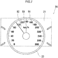
- the display control unit 13 determines, as a display mode, a third mode in which an own vehicle speed and a setting speed are displayed as illustrated in FIG. 7 , and displays each piece of display information. Thereafter, the control proceeds to Step S13.
- Step S8 when the flag A is not set (NO in Step S8), the control proceeds to Step S12.
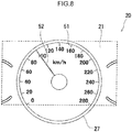
- the display control unit 13 determines, as a display mode, an ordinary mode in which only an own vehicle speed as illustrated in FIG. 8 is displayed, and displays the own vehicle speed. Thereafter, the control proceeds to Step S13.
- Step S13 determination is made whether ignition is off.
- the control is terminated.
- the control returns to Step S1, and repeats the above-described flow.
- a display mode is determined as described above, and the display unit 20 displays predetermined speed information in the determined display mode.
- speed information that is arbitrarily settable by a driver is referred to as a "first speed”
- speed information that is not arbitrarily settable by a driver is referred to as a "second speed”.
- first speed speed information that is arbitrarily settable by a driver
- second speed speed information that is not arbitrarily settable by a driver
- the setting speed belongs to the first speed.
- a limiting speed is recognized by the sign recognition unit 11, and cannot be arbitrarily set, the limiting speed belongs to the second speed.
- the first speed can be set by a driver himself/herself, the first speed has a feature such that the driver relatively easily recognizes.
- the second speed cannot be set by a driver himself/herself, the second speed has a feature such that the driver is relatively less likely to recognize.
- the display device 100 displays a setting speed for constant speed driving control (specifically, drawings of the speed scale 51 and the setting speed pointer 53) on the inner side of a circular area surrounded by the circular frame member 27; and displays a limiting speed (specifically, a drawing of the simulated sign 54) on the outer side of the area surrounded by the circular frame member 27.
- a setting speed for constant speed driving control specifically, drawings of the speed scale 51 and the setting speed pointer 53
- a limiting speed specifically, a drawing of the simulated sign 54
- speed information displayed on the inner side of the circular frame member 27 is displayed on the inner side of the circular frame member 27. Further, speed information displayed on the outer side of the circular frame member 27 is an unexpected indication to a driver, and the driver can easily recognize that the speed information is of a type different from an own vehicle speed.
- a setting speed for constant speed driving control is displayed on the inner side of an area surrounded by the circular frame member 27, and a limiting speed is displayed on the outer side of the area surrounded by the circular frame member 27. Therefore, a limiting speed is easily recognized as a speed of a type different from an own vehicle speed and a setting speed.
- a limiting speed is easily recognized as a speed of a type different from an own vehicle speed and a setting speed.
- the display device 100 displays the simulated sign 54, and emphasizes a portion of the speed scale 51 associated with the limiting speed, as compared with the other portion.
- the display device 100 may display only the simulated sign 54, and may not emphasize a portion of the speed scale 51 associated with a limiting speed.
- the display unit 20 in the present embodiment includes the display 21 having a display area spanning an inner side and an outer side of the circular frame member 27.
- the display unit 20 may include a plurality of displays respectively serving as display areas on an inner side and an outer side of the circular frame member 27.
- a setting speed for constant speed driving control is described as an example of the first speed that is arbitrarily settable.
- the first speed is not limited to a setting speed for constant speed driving control.
- a limiting speed is described as an example of the second speed that is not arbitrarily settable.
- the second speed is not limited to a limiting speed.
- a display device is mounted in an automobile.
- a display device may be mounted in a moving body other than an automobile, such as a motorcycle.
- a display device may be mounted in a moving body, which is not limited to an automobile.
- "a vehicle”, “a driver”, “an own vehicle speed”, and “an own vehicle speed pointer” in the present embodiment are respectively read as “a moving body”, “an operator”, “a moving body speed”, and “a moving body speed pointer”.
- a display device is a display device for displaying information relating to at least a moving body to a driver of the moving body.
- the display device includes a display unit for displaying a moving body speed being a speed of the moving body, a first speed that is arbitrarily settable by the driver, and a second speed that is not arbitrarily settable by the driver.
- the display unit displays the first speed and the second speed in ways different from each other.
- the first speed is a speed that is arbitrarily settable by a driver.
- the first speed is speed information set by a driver himself/herself
- the second speed is a speed that is not arbitrarily settable by a driver.
- the second information is not speed information that is set by a driver himself/herself
- the second speed is relatively less likely to be recognized by the driver.
- the display unit may include a display having a drawing function, and a frame member disposed to overlap the display.
- the display may include a display area spanning an inner side and an outer side of the frame member.
- the display may display the moving body speed and the first speed on the inner side of the frame member, and display the second speed on the outer side of the frame member.
- a drawing function is a so-called image display function, and is a function of displaying an image such as a figure, a character, and a number.
- an own vehicle speed is displayed by using a meter of a circular frame shape.
- speed information is displayed on the inner side of an area surrounded by a frame member.
- Many drivers may subconsciously conceive that speed information is displayed on the inner side of an area surrounded by a frame member.
- a driver may be aware that the speed information is special information, and pay attention to the speed information. Therefore, in the display device having the above configuration, by disposing the second speed, which is relatively less likely to be recognized by a driver, on the outer side of a frame member, a driver easily recognizes the second speed. Consequently, it is possible to appropriately convey each piece of speed information to a driver.
- the display device having the above configuration may further include a setting information acquisition unit for acquiring a setting speed for constant speed driving control that is arbitrarily set by the driver.
- the first speed may be the setting speed for constant speed driving control.
- the display device is able to display a setting speed for constant speed driving control, which is set by a driver himself/herself in such a way that the driver easily recognizes the setting speed.
- the display device having the above configuration may further include a sign recognition unit for recognizing a limiting speed written on a speed sign installed on an outside of the moving body.
- the second speed may be the limiting speed recognized by the sign recognition unit.
- the display device is able to display a limiting speed, which cannot be set by a driver himself/herself, and is relatively less likely to be recognized by the driver, in such a way that the driver easily recognizes the limiting speed.
- the frame member may have a circular shape.
- the display may display a speed scale along the frame member, a moving body speed pointer for designating a value of the speed scale associated with the moving body speed, a setting speed pointer for designating a value of the speed scale associated with the setting speed for constant speed driving control, the moving body speed by the speed scale and the moving body speed pointer, and the setting speed by the speed scale and the setting speed pointer.
- the frame member may have a circular shape.
- the display may draw a speed scale along the frame member, a moving body speed pointer for designating a value of the speed scale associated with the moving body speed, and a simulated sign simulating a speed sign associated with a limiting speed recognized by the sign recognition unit.
- the display may display the moving body speed by the speed scale and the moving body speed pointer, and display the limiting speed by the simulated sign.
- the display may display a portion of the speed scale associated with the limiting speed in an emphasized manner, as compared with the other portion.
- the display may display an area of the speed scale from a portion associated with the limiting speed to a portion associated with the moving body speed in an emphasized manner, as compared with the other area.
- a driver can instinctively recognize whether the moving body speed exceeds the limiting speed, and, when the moving body speed exceeds the limiting speed, an amount of excess of the moving body speed. Therefore, in the display device having the above configuration, it is possible to appropriately convey each piece of speed information to a driver.
Landscapes
- Engineering & Computer Science (AREA)
- Mechanical Engineering (AREA)
- Chemical & Material Sciences (AREA)
- Transportation (AREA)
- Combustion & Propulsion (AREA)
- Physics & Mathematics (AREA)
- General Physics & Mathematics (AREA)
- Theoretical Computer Science (AREA)
- Atmospheric Sciences (AREA)
- Life Sciences & Earth Sciences (AREA)
- Computer Hardware Design (AREA)
- Multimedia (AREA)
- Instrument Panels (AREA)
- Indicating Measured Values (AREA)
- Controls And Circuits For Display Device (AREA)
- Devices For Indicating Variable Information By Combining Individual Elements (AREA)
Abstract
Description
- The present invention relates to a display device for displaying information such as a speed to a driver of a moving body such as a vehicle.
- A display device (meter device) for displaying information to a driver is provided on a front side of a driver's seat of a moving body such as a vehicle. In recent years, the display device may also display, in addition to a speed of a vehicle (own vehicle speed) at a point of time when the own vehicle speed is displayed, speed information on a speed other than the own vehicle speed. For example,
Patent Literature 1 proposes a display device for displaying a predetermined recognition speed, in addition to an own vehicle speed. - When the number of types of speed information to be displayed on a display device increases, how to display each piece of the speed information, and how to let a driver recognize become issues. In this regard, the inventors of the present invention found that some pieces of speed information are relatively easily recognized, and some pieces of speed information are relatively less likely to be recognized by a driver depending on a type of speed information.
- Patent Literature 1: Japanese Unexamined Patent Application Publication No.
2010-143407 - In view of the above, an object of the present invention is to provide a display device that enables to appropriately convey each piece of speed information to a driver, based on determination as to whether the speed information is speed information easily recognized by a driver of a moving body.
- A display device according to the present invention is a display device for displaying information relating to at least a moving body to a driver of the moving body. The display device includes a display unit for displaying a moving body speed being a speed of the moving body, a first speed that is arbitrarily settable by the driver, and a second speed that is not arbitrarily settable by the driver. The display unit displays the first speed and the second speed in ways different from each other.
-
-
FIG. 1 is a block diagram of a display device. -
FIG. 2 is an exploded perspective view of a display unit. -
FIG. 3 is a diagram illustrating the display unit, when a display is in a non-display state. -
FIG. 4 is a diagram illustrating the display unit, when the display displays each piece of speed information, and illustrates a display content in a first mode. -
FIG. 5 is a flowchart illustrating a flow of control of determining a display mode. -
FIG. 6 is a diagram illustrating a display content in a second mode. -
FIG. 7 is a diagram illustrating a display content in a third mode. -
FIG. 8 is a diagram illustrating a display content in an ordinary mode. - In the following, a display device according to an embodiment of the present invention is described.
- First, an entire configuration of a display device is described.
FIG. 1 is a block diagram of a control system of adisplay device 100. As illustrated inFIG. 1 , thedisplay device 100 includes acontrol device 10 and adisplay unit 20. Thedisplay device 100 is mounted on an instrument panel (not illustrated), which is disposed on a front side of a driver's seat of a vehicle as a moving body. Thedisplay device 100 displays various types of information to a driver seated on the driver's seat. The embodiment of the present invention describes a vehicle, more specifically, an automobile, as a moving body. The present invention, however, may be applied to a moving body other than a vehicle. - The
control device 10 is constituted by a CPU, a ROM, a RAM, and the like. Further, thecontrol device 10 is electrically connected to acamera 101 for photographing outside of a vehicle, avehicle speed sensor 102 for measuring an own vehicle speed, and a constant speeddriving setting unit 103 for performing setting on constant speed driving control. Thecontrol device 10 acquires vehicle-outside video information, own vehicle speed information, and constant speed driving setting information, respectively, based on a signal to be transmitted from the pieces of equipment (101 to 103). Further, thecontrol device 10 performs various calculations, based on pieces of information acquired from the pieces of equipment, and transmits a control signal to thedisplay unit 20. - In this section, constant speed driving control is described. Constant speed driving control includes control (cruise control) of simply driving a vehicle at a constant speed, and control (active cruise control) of driving a vehicle at a constant speed, when there is a distance equal to or larger than a fixed value with respect to a preceding vehicle. A driver can arbitrarily set whether constant speed driving control is performed, and a speed when constant speed driving is performed by using the constant speed
driving setting unit 103. In the following, when a "setting speed" is simply mentioned, the "setting speed" means a speed of constant speed driving set by the constant speeddriving setting unit 103. - Further, the
control device 10 includes, as a functional configuration, asign recognition unit 11, a settinginformation acquisition unit 12, and adisplay control unit 13. Among these elements, thesign recognition unit 11 recognizes a limiting speed written on a speed sign, which is installed on the outside of a vehicle, based on vehicle-outside video information acquired from thecamera 101. Further, the settinginformation acquisition unit 12 acquires constant speed driving setting information set by the constant speeddriving setting unit 103, namely, information indicating whether constant speed driving control is performed, and information on a set setting speed. Furthermore, thedisplay control unit 13 controls adisplay 21 by transmitting a control signal to thedisplay 21 of thedisplay unit 20, which is described later. - The
display unit 20 includes thedisplay 21 having a drawing function. Thedisplay 21 displays a predetermined content including each piece of speed information, based on a control signal transmitted from thedisplay control unit 13. In this example, thedisplay 21 is, for example, a liquid crystal display, and the drawing function is a function of displaying an image such as a figure, a character, and a number, which is stored in advance (or given by communication). Details on thedisplay unit 20 are described in the following. - Next, a configuration of the
display unit 20 is described in detail.FIG. 2 is an exploded perspective view of thedisplay unit 20. As illustrated inFIG. 2 , thedisplay unit 20 includes, in addition to thedisplay 21, abase plate 22, ascreen 23, atachometer pointer 24, a watertemperature meter pointer 25, afuel meter pointer 26, acircular frame member 27, aframe member 28 for a tachometer, aframe member 29 for a water temperature meter and a fuel meter, anouter perimeter cover 30, and asurface cover 31. - The
base plate 22 includes aninsertion portion 36 for receiving thedisplay 21. When thedisplay 21 is received in theinsertion portion 36, a surface of thedisplay 21 and a surface of thebase plate 22 are located on a same plane. Further, thebase plate 22 includes atachometer driving motor 37 for driving thetachometer pointer 24, a water temperaturemeter driving motor 38 for driving the watertemperature meter pointer 25, and a fuelmeter driving motor 39 for driving thefuel meter pointer 26. For convenience of explanation, inFIG. 2 , only drive axes of therespective motors - The
screen 23 is a member for covering a surface of thedisplay 21 and a surface of thebase plate 22. A portion of thescreen 23 associated with thedisplay 21 is transparent and has light transparency. On the other hand, a portion of thescreen 23 other than the portion associated with thedisplay 21 is coated black, for example, and does not have light transparency. Further, through-holes screen 23 respectively associated with thedriving motors driving motor holes screen 23 associated with thetachometer pointer 24, a scale for a water temperature meter is drawn on a portion of thescreen 23 associated with the watertemperature meter pointer 25, and a scale for a fuel meter is drawn on a portion of thescreen 23 associated with the fuel meter pointer 26 (also seeFIG. 3 ). - The
tachometer pointer 24 is mounted on the drive axis of thetachometer driving motor 37, and designates an engine rotation number at a point of time when measurement is performed. Further, the watertemperature meter pointer 25 is mounted on the drive axis of the water temperaturemeter driving motor 38, and designates a temperature of cooling water at a point of time when measurement is performed. Thefuel meter pointer 26 is mounted on the drive axis of the fuelmeter driving motor 39, and designates an amount of fuel inside a fuel tank at a point of time when measurement is performed. - The
circular frame member 27 is a circular frame member located at a middle of thedisplay unit 20. Thecircular frame member 27 in the present embodiment is constituted by an annular-shapedbase ring 32, and an annular-shapeddecorative ring 33 for covering thebase ring 32 from above.FIG. 3 is a diagram of thedisplay unit 20 viewed from a driver's seat when thedisplay 21 is in a non-display state. An area surrounded by a broken line inFIG. 3 indicates a display area of thedisplay 21. As illustrated inFIG. 3 , thecircular frame member 27 is disposed over thedisplay 21. Thedisplay 21 has a display area spanning an inner side and an outer side of thecircular frame member 27. - The
tachometer frame member 28 is a frame member of an arc shape (circular shape in which a part is missing). Thetachometer frame member 28 is disposed on a portion of thescreen 23 where a tachometer scale is drawn. Further, theframe member 29 for a water temperature meter and a fuel meter is a frame member of an arc shape (circular shape in which a part is missing). Theframe member 29 is disposed on a portion of thescreen 23 where a scale of a water temperature meter and a scale of a fuel meter are drawn. Although a part of thetachometer frame member 28 and a part of theframe member 29 for a water temperature meter and a fuel meter overlap thedisplay 21, thetachometer pointer 24, the watertemperature meter pointer 25, and thefuel meter pointer 26 are located on the outer side of thedisplay 21. - The
outer perimeter cover 30 is a member for defining an outer perimeter of thedisplay unit 20. Thesurface cover 31 is a member having light transparency, and configured to cover a surface of thescreen 23 from outside of theframe members 27 to 29 and thepointers 24 to 26 (from the driver's seat side). - Next, a display pattern of each piece of speed information by the
display unit 20 is described.FIG. 4 is a diagram of thedisplay unit 20, when viewed from a driver's seat side, and illustrates a state that thedisplay 21 displays each piece of speed information. Thedisplay 21 displays, as speed information, an own vehicle speed being a speed of a vehicle at a point of time when measurement is performed, a setting speed for constant speed driving control, and a limiting speed recognized by thesign recognition unit 11. Specifically, thedisplay 21 displays aspeed scale 51, an ownvehicle speed pointer 52, asetting speed pointer 53, and asimulated sign 54. - The
speed scale 51 is a scale indicating a speed. Thespeed scale 51 is drawn on the inside of thecircular frame member 27 along thecircular frame member 27. - The own
vehicle speed pointer 52 is a movable pointer indicating an own vehicle speed. The ownvehicle speed pointer 52 is located on the inner side of thecircular frame member 27, and designates a value of thespeed scale 51 associated with the own vehicle speed. Note that the ownvehicle speed pointer 52 is indicated as an image analogous to a real meter pointer. In this way, in the present embodiment, an own vehicle speed is displayed on the inner side of a circular area surrounded by thecircular frame member 27 by thespeed scale 51 and theown vehicle pointer 52. In other words, an own vehicle speed is displayed in a way similar to a conventional analog speed meter. - The
setting speed pointer 53 is a fixed pointer indicating a setting speed for constant speed driving control. Thesetting speed pointer 53 is drawn, when a setting speed for constant speed driving control is set by the constant speed drivingsetting unit 103. Further, thesetting speed pointer 53 is located on the inner side of thecircular frame member 27, and fixedly designates a value of thespeed scale 51 associated with a setting speed. Thesetting speed pointer 53 is indicated by a broken line. In this way, a setting speed for constant speed driving control is displayed on the inner side of a circular area surrounded by thecircular frame member 27 by thespeed scale 51 and thesetting speed pointer 53. - The
simulated sign 54 simulates a speed sign associated with a limiting speed recognized by thesign recognition unit 11. For example, when a speed sign defined by regulations is a sign such that a limiting speed is written within a red circle, thedisplay unit 20 draws an image such that a limiting speed is written within a red circle, as thesimulated sign 54. Thesimulated sign 54 is drawn, when thesign recognition unit 51 recognizes a limiting speed. Further, thesimulated sign 54 is located on the outer side of thecircular frame member 27, and near theframe member 29 for a water temperature meter and a fuel meter. In this way, a limiting speed recognized by thesign recognition unit 11 is displayed on the outer side of a circular area surrounded by thecircular frame member 27 by thesign recognition unit 11. - In the present embodiment, when the
sign recognition unit 11 recognizes a limiting speed, in addition to that thesimulated sign 54 is drawn, a portion of thespeed scale 51 associated with the limiting speed is emphasized, as compared with the other portion. Specifically, thedisplay 21 draws amark 55 at a portion of thespeed scale 51 associated with a limiting speed. Further, when an own vehicle speed exceeds the limiting speed, an area of thespeed scale 51 from a portion associated with the limiting speed to a portion associated with the own vehicle speed is emphasized, as compared with the other area. Specifically, thedisplay 21 draws a band-shapedarch 56 in an area of thespeed scale 51 from a portion associated with a limiting speed to a portion associated with an own vehicle speed. - Next, a display mode of each piece of speed information to be displayed by the
display unit 20 is described. Thedisplay unit 20 illustrated inFIG. 4 displays all speeds, namely, an own vehicle speed, a setting speed, and a limiting speed. However, it is not always the case that thedisplay unit 20 displays all the speeds constantly. A display mode associated with speed information to be displayed, namely, a display speed to be displayed is determined depending on a condition. Determination of a display mode is performed by thedisplay control unit 13. -
FIG. 5 is a flowchart illustrating a flow of control of determining a display mode. The control is started in response to turning on of ignition. When the control is started, thedisplay control unit 13 acquires an own vehicle speed (Step S1). Subsequently, determination is made as to whether a limiting speed is recognized by the sign recognition unit 11 (Step S2). When the limiting speed is recognized (YES in Step S2), the recognized limiting speed is acquired, and a flag T is set (Step S3). Thereafter, the control proceeds to Step S4. On the other hand, when the limiting speed is not recognized (NO in Step S2), the control proceeds to Step S4 without proceeding to Step S3. - Subsequently, in Step S4, determination is made as to whether a setting speed for constant speed driving control is set. When the setting speed is set (YES in Step S4), the set setting speed is acquired, and a flag A is set (Step S5). Thereafter, the control proceeds to Step S6. On the other hand, when the setting speed is not set (NO in Step S4), the control proceeds to Step S6 without proceeding to Step S5.
- Subsequently, in Step S6, determination is made as to whether the flag T is set. When the flag T is set (YES in Step S6), the control proceeds to Step S7. On the other hand, when the flag T is not set (NO in Step S6), the control proceeds to Step S8.
- Subsequently, in Step S7, determination is made as to whether the flag A is set. When the flag A is set (YES in Step S7), the control proceeds to Step S9. At a point of time when the control proceeds to Step S9, since all the speeds, namely, an own vehicle speed, a limiting speed, and a setting speed are acquired, the
display control unit 13 determines, as a display mode, a first mode in which all the speeds, namely, an own vehicle speed, a limiting speed, and a setting speed as illustrated inFIG. 4 are displayed, and displays each piece of display information. Thereafter, the control proceeds to Step S13. - On the other hand, in Step S7, when the flag A is not set (NO in Step S7), the control proceeds to Step S10. At a point of time when the control proceeds to Step S10, since an own vehicle speed and a limiting speed are acquired, the
display control unit 13 determines, as a display mode, a second mode in which an own vehicle speed and a limiting speed as illustrated inFIG. 6 are displayed, and displays each piece of display information. Thereafter, the control proceeds to Step S13. - Subsequently, in Step S8, determination is made as to whether the flag A is set. When the flag A is set (YES in Step S8), the control proceeds to Step S11. At a point of time when the control proceeds to Step S11, since an own vehicle speed and a setting speed are acquired, the
display control unit 13 determines, as a display mode, a third mode in which an own vehicle speed and a setting speed are displayed as illustrated inFIG. 7 , and displays each piece of display information. Thereafter, the control proceeds to Step S13. - On the other hand, in Step S8, when the flag A is not set (NO in Step S8), the control proceeds to Step S12. At a point of time when the control proceeds to Step S12, since only an own vehicle speed is acquired, the
display control unit 13 determines, as a display mode, an ordinary mode in which only an own vehicle speed as illustrated inFIG. 8 is displayed, and displays the own vehicle speed. Thereafter, the control proceeds to Step S13. - Subsequently, in Step S13, determination is made whether ignition is off. When ignition is off (YES in Step S13), the control is terminated. On the other hand, when ignition is not off (NO in Step S13), the control returns to Step S1, and repeats the above-described flow.
- In the present embodiment, a display mode is determined as described above, and the
display unit 20 displays predetermined speed information in the determined display mode. - In this section, among various types of speed information, speed information that is arbitrarily settable by a driver is referred to as a "first speed", and speed information that is not arbitrarily settable by a driver is referred to as a "second speed". Among the above-described pieces of speed information, since a setting speed for constant speed driving control is settable by the constant speed driving
setting unit 103, the setting speed belongs to the first speed. Further, since a limiting speed is recognized by thesign recognition unit 11, and cannot be arbitrarily set, the limiting speed belongs to the second speed. - Since the first speed can be set by a driver himself/herself, the first speed has a feature such that the driver relatively easily recognizes. On the other hand, since the second speed cannot be set by a driver himself/herself, the second speed has a feature such that the driver is relatively less likely to recognize. Taking into consideration these features, in the
display device 100 according to the present embodiment, a setting speed for constant speed driving control belonging to the first speed, and a limiting speed belonging to the second speed are displayed in different ways (including a display position and a display method). - Specifically, the
display device 100 displays a setting speed for constant speed driving control (specifically, drawings of thespeed scale 51 and the setting speed pointer 53) on the inner side of a circular area surrounded by thecircular frame member 27; and displays a limiting speed (specifically, a drawing of the simulated sign 54) on the outer side of the area surrounded by thecircular frame member 27. In the present embodiment, by disposing thecircular frame member 27 to overlap thedisplay 21, and displaying an own vehicle speed on the inner side of thecircular frame member 27 by using thespeed scale 51 and the ownvehicle speed pointer 52, a driver can imagine a conventional analog speed meter. A conventional analog speed meter displays speed information (own vehicle speed) on the inner side of an area surrounded by a circular frame. Therefore, in the above-described configuration, a driver can intuitively and empirically understand that speed information is displayed on the inner side of thecircular frame member 27. Further, speed information displayed on the outer side of thecircular frame member 27 is an unexpected indication to a driver, and the driver can easily recognize that the speed information is of a type different from an own vehicle speed. - In the present embodiment, taking into consideration such a psychological influence to a driver, a setting speed for constant speed driving control is displayed on the inner side of an area surrounded by the
circular frame member 27, and a limiting speed is displayed on the outer side of the area surrounded by thecircular frame member 27. Therefore, a limiting speed is easily recognized as a speed of a type different from an own vehicle speed and a setting speed. Thus, in thedisplay device 100 according to the present embodiment, it is possible to appropriately convey each piece of speed information to a driver. - In the foregoing embodiment, when the
sign recognition unit 11 recognizes a limiting speed, thedisplay device 100 displays thesimulated sign 54, and emphasizes a portion of thespeed scale 51 associated with the limiting speed, as compared with the other portion. Alternatively, thedisplay device 100 may display only thesimulated sign 54, and may not emphasize a portion of thespeed scale 51 associated with a limiting speed. - Further, the
display unit 20 in the present embodiment includes thedisplay 21 having a display area spanning an inner side and an outer side of thecircular frame member 27. Alternatively, thedisplay unit 20 may include a plurality of displays respectively serving as display areas on an inner side and an outer side of thecircular frame member 27. - Furthermore, in the present embodiment, a setting speed for constant speed driving control is described as an example of the first speed that is arbitrarily settable. As far as a speed is arbitrarily settable, the first speed is not limited to a setting speed for constant speed driving control. Likewise, in the present embodiment, a limiting speed is described as an example of the second speed that is not arbitrarily settable. As far as a speed is not arbitrarily settable, the second speed is not limited to a limiting speed.
- In the present embodiment, a case is described in which a display device is mounted in an automobile. As described above, however, a display device may be mounted in a moving body other than an automobile, such as a motorcycle. In other words, a display device may be mounted in a moving body, which is not limited to an automobile. In this case, "a vehicle", "a driver", "an own vehicle speed", and "an own vehicle speed pointer" in the present embodiment are respectively read as "a moving body", "an operator", "a moving body speed", and "a moving body speed pointer".
- The following is an overview of the present invention described above.
- A display device according to an aspect of the present invention is a display device for displaying information relating to at least a moving body to a driver of the moving body. The display device includes a display unit for displaying a moving body speed being a speed of the moving body, a first speed that is arbitrarily settable by the driver, and a second speed that is not arbitrarily settable by the driver. The display unit displays the first speed and the second speed in ways different from each other.
- The first speed is a speed that is arbitrarily settable by a driver. In other words, since the first speed is speed information set by a driver himself/herself, the first speed is relatively easily recognized by the driver. On the other hand, the second speed is a speed that is not arbitrarily settable by a driver. In other words, since the second information is not speed information that is set by a driver himself/herself, the second speed is relatively less likely to be recognized by the driver. In view of this, in the display device having the above configuration, since the first speed and the second speed are displayed in ways different from each other, a driver can recognize these pieces of speed information without confusion. Consequently, it is possible to appropriately convey each piece of speed information to a driver.
- Further, in the display device having the above configuration, the display unit may include a display having a drawing function, and a frame member disposed to overlap the display. The display may include a display area spanning an inner side and an outer side of the frame member. The display may display the moving body speed and the first speed on the inner side of the frame member, and display the second speed on the outer side of the frame member. Note that a drawing function is a so-called image display function, and is a function of displaying an image such as a figure, a character, and a number.
- In a conventional analog display device, an own vehicle speed is displayed by using a meter of a circular frame shape. In other words, in a conventional display device, it is often the case that speed information is displayed on the inner side of an area surrounded by a frame member. Many drivers may subconsciously conceive that speed information is displayed on the inner side of an area surrounded by a frame member. In view of the above, when speed information is displayed on the outer side of an area surrounded by a frame member, a driver may be aware that the speed information is special information, and pay attention to the speed information. Therefore, in the display device having the above configuration, by disposing the second speed, which is relatively less likely to be recognized by a driver, on the outer side of a frame member, a driver easily recognizes the second speed. Consequently, it is possible to appropriately convey each piece of speed information to a driver.
- Further, the display device having the above configuration may further include a setting information acquisition unit for acquiring a setting speed for constant speed driving control that is arbitrarily set by the driver. The first speed may be the setting speed for constant speed driving control.
- In the above configuration, the display device is able to display a setting speed for constant speed driving control, which is set by a driver himself/herself in such a way that the driver easily recognizes the setting speed.
- Further, the display device having the above configuration may further include a sign recognition unit for recognizing a limiting speed written on a speed sign installed on an outside of the moving body. The second speed may be the limiting speed recognized by the sign recognition unit.
- In the above configuration, the display device is able to display a limiting speed, which cannot be set by a driver himself/herself, and is relatively less likely to be recognized by the driver, in such a way that the driver easily recognizes the limiting speed.
- Further, in the display device having the above configuration, the frame member may have a circular shape. The display may display a speed scale along the frame member, a moving body speed pointer for designating a value of the speed scale associated with the moving body speed, a setting speed pointer for designating a value of the speed scale associated with the setting speed for constant speed driving control, the moving body speed by the speed scale and the moving body speed pointer, and the setting speed by the speed scale and the setting speed pointer.
- In the above configuration, it is possible to more appropriately convey each piece of speed information to a driver.
- Further, in the display method having the above configuration, the frame member may have a circular shape. The display may draw a speed scale along the frame member, a moving body speed pointer for designating a value of the speed scale associated with the moving body speed, and a simulated sign simulating a speed sign associated with a limiting speed recognized by the sign recognition unit. The display may display the moving body speed by the speed scale and the moving body speed pointer, and display the limiting speed by the simulated sign.
- In the above configuration, since the moving body speed and the limiting speed are different from each other in terms of not only a display position but also a display method (indication method), it is possible to more appropriately convey each piece of speed information to a driver.
- Further, in the above display device, the display may display a portion of the speed scale associated with the limiting speed in an emphasized manner, as compared with the other portion. When the moving body speed exceeds the limiting speed, the display may display an area of the speed scale from a portion associated with the limiting speed to a portion associated with the moving body speed in an emphasized manner, as compared with the other area.
- In the above configuration, a driver can instinctively recognize whether the moving body speed exceeds the limiting speed, and, when the moving body speed exceeds the limiting speed, an amount of excess of the moving body speed. Therefore, in the display device having the above configuration, it is possible to appropriately convey each piece of speed information to a driver.
Claims (7)
- A display device for displaying information relating to at least a moving body to a driver of the moving body, comprising
a display unit for displaying
a moving body speed being a speed of the moving body,
a first speed that is arbitrarily settable by the driver, and
a second speed that is not arbitrarily settable by the driver, wherein
the display unit displays the first speed and the second speed in ways different from each other. - The display device according to claim 1, wherein
the display unit includes
a display having a drawing function, and
a frame member disposed to overlap the display,
the display includes a display area spanning an inner side and an outer side of the frame member, and
the display displays the moving body speed and the first speed on the inner side of the frame member, and displays the second speed on the outer side of the frame member. - The display device according to claim 2, further comprising
a setting information acquisition unit for acquiring a setting speed for constant speed driving control that is arbitrarily set by the driver, wherein
the first speed is the setting speed for constant speed driving control. - The display device according to claim 2, further comprising
a sign recognition unit for recognizing a limiting speed written on a speed sign installed on an outside of the moving body, wherein
the second speed is the limiting speed recognized by the sign recognition unit. - The display device according to claim 3, wherein
the frame member has a circular shape, and
the display displays
a speed scale along the frame member,
a moving body speed pointer for designating a value of the speed scale associated with the moving body speed,
a setting speed pointer for designating a value of the speed scale associated with the setting speed for constant speed driving control,
the moving body speed by the speed scale and the moving body speed pointer, and
the setting speed by the speed scale and the setting speed pointer. - The display device according to claim 3, wherein
the frame member has a circular shape,
the display draws
a speed scale along the frame member,
a moving body speed pointer for designating a value of the speed scale associated with the moving body speed, and
a simulated sign simulating a speed sign associated with a limiting speed recognized by the sign recognition unit, and
the display displays the moving body speed by the speed scale and the moving body speed pointer, and displays the limiting speed by the simulated sign. - The display device according to claim 6, wherein
the display displays a portion of the speed scale associated with the limiting speed in an emphasized manner, as compared with the other portion, and
when the moving body speed exceeds the limiting speed, the display displays an area of the speed scale from a portion associated with the limiting speed to a portion associated with the moving body speed in an emphasized manner, as compared with the other area.
Applications Claiming Priority (2)
| Application Number | Priority Date | Filing Date | Title |
|---|---|---|---|
| JP2017027679A JP6481698B2 (en) | 2017-02-17 | 2017-02-17 | Display device |
| PCT/JP2018/005230 WO2018151205A1 (en) | 2017-02-17 | 2018-02-15 | Display device |
Publications (2)
| Publication Number | Publication Date |
|---|---|
| EP3569437A1 true EP3569437A1 (en) | 2019-11-20 |
| EP3569437A4 EP3569437A4 (en) | 2020-01-15 |
Family
ID=63169914
Family Applications (1)
| Application Number | Title | Priority Date | Filing Date |
|---|---|---|---|
| EP18754599.1A Withdrawn EP3569437A4 (en) | 2017-02-17 | 2018-02-15 | DISPLAY DEVICE |
Country Status (5)
| Country | Link |
|---|---|
| US (1) | US10773593B2 (en) |
| EP (1) | EP3569437A4 (en) |
| JP (1) | JP6481698B2 (en) |
| CN (1) | CN110290966A (en) |
| WO (1) | WO2018151205A1 (en) |
Families Citing this family (1)
| Publication number | Priority date | Publication date | Assignee | Title |
|---|---|---|---|---|
| JP7837858B2 (en) * | 2022-12-28 | 2026-03-31 | 株式会社クボタ | Remote devices and remote control systems |
Family Cites Families (19)
| Publication number | Priority date | Publication date | Assignee | Title |
|---|---|---|---|---|
| DE3622632C2 (en) * | 1986-07-05 | 1995-11-30 | Fichtel & Sachs Ag | Electronic device for measuring and displaying the speed and other data on a bicycle |
| DE4325721A1 (en) * | 1993-07-30 | 1995-02-02 | Bayerische Motoren Werke Ag | Display device |
| WO1998038059A1 (en) | 1997-02-24 | 1998-09-03 | Marius Tegethoff | Motor vehicle display system |
| DE19736774A1 (en) * | 1997-08-23 | 1999-02-25 | Bosch Gmbh Robert | Information display method in vehicle |
| JP3799837B2 (en) * | 1998-10-16 | 2006-07-19 | 株式会社デンソー | Notification device for cruise control device |
| JP3838613B2 (en) * | 1999-08-31 | 2006-10-25 | 本田技研工業株式会社 | In-vehicle display device |
| US6690300B1 (en) * | 2000-10-11 | 2004-02-10 | Delphi Technologies, Inc. | Marine engine throttle control method for single or twin engine applications |
| JP2006056276A (en) * | 2004-08-17 | 2006-03-02 | Honda Motor Co Ltd | Electric vehicle display device |
| US7589643B2 (en) * | 2005-06-30 | 2009-09-15 | Gm Global Technology Operations, Inc. | Vehicle speed monitoring system |
| JP4882499B2 (en) * | 2006-05-10 | 2012-02-22 | 株式会社デンソー | Speed information providing apparatus and program |
| KR100911566B1 (en) * | 2008-04-29 | 2009-08-10 | 현대자동차주식회사 | Car digital integrated information instrument panel |
| JP2010143407A (en) | 2008-12-18 | 2010-07-01 | Aisin Aw Co Ltd | Display device, display method, and display program |
| JP2011218889A (en) * | 2010-04-06 | 2011-11-04 | Denso Corp | Speed display device for vehicle |
| DE102010027831A1 (en) | 2010-04-15 | 2011-10-20 | Robert Bosch Gmbh | Method and navigation device for determining a maximum possible residual vehicle speed |
| JP5427202B2 (en) * | 2011-03-29 | 2014-02-26 | 富士重工業株式会社 | Vehicle driving support device |
| JP2015021927A (en) * | 2013-07-23 | 2015-02-02 | 日産自動車株式会社 | Display device for vehicle and display method for the same |
| JP6237658B2 (en) * | 2015-01-20 | 2017-11-29 | マツダ株式会社 | Vehicle display device |
| JP6353434B2 (en) * | 2015-12-22 | 2018-07-04 | 本田技研工業株式会社 | Regulation information notification device and method |
| US11046242B2 (en) * | 2017-02-09 | 2021-06-29 | Ford Global Technologies, Llc | Display for rear lamp of a vehicle |
-
2017
- 2017-02-17 JP JP2017027679A patent/JP6481698B2/en not_active Expired - Fee Related
-
2018
- 2018-02-15 EP EP18754599.1A patent/EP3569437A4/en not_active Withdrawn
- 2018-02-15 CN CN201880011357.6A patent/CN110290966A/en active Pending
- 2018-02-15 WO PCT/JP2018/005230 patent/WO2018151205A1/en not_active Ceased
- 2018-02-15 US US16/484,919 patent/US10773593B2/en not_active Expired - Fee Related
Also Published As
| Publication number | Publication date |
|---|---|
| EP3569437A4 (en) | 2020-01-15 |
| JP2018131138A (en) | 2018-08-23 |
| US10773593B2 (en) | 2020-09-15 |
| JP6481698B2 (en) | 2019-03-13 |
| CN110290966A (en) | 2019-09-27 |
| US20200055398A1 (en) | 2020-02-20 |
| WO2018151205A1 (en) | 2018-08-23 |
Similar Documents
| Publication | Publication Date | Title |
|---|---|---|
| US7369044B2 (en) | Display apparatus for vehicle | |
| JP6808894B2 (en) | Vehicle alarm device | |
| US7683771B1 (en) | Configurable control panel and/or dashboard display | |
| US7605693B2 (en) | Visual indicators on vehicle steering wheel displayed in response to hand position | |
| US6693523B1 (en) | Instrument cluster for motor vehicles with variable-color display | |
| US8866736B2 (en) | Gaze detection apparatus and method | |
| US20110163864A1 (en) | Display device for vehicle | |
| KR20060127213A (en) | Vehicle information display device and vehicle information display method | |
| US9959838B2 (en) | Transparent display overlay systems for vehicle instrument cluster assemblies | |
| JP2006001377A (en) | Vehicle display device | |
| CN114248624B (en) | Vehicle display device | |
| JP5740669B2 (en) | System and program | |
| JP2012040965A (en) | Display device for vehicle | |
| US10773593B2 (en) | Display device | |
| JP2016068931A (en) | Speed display device and speed display method | |
| JP2012192799A (en) | Vehicle information display system and program | |
| KR20120032596A (en) | Display method of cluster for vehicle using transparent display | |
| JP4251141B2 (en) | Meters and instrument pointer display methods | |
| JP2012192800A (en) | Vehicle information display system and program | |
| JPH0790727B2 (en) | Vehicle display | |
| JP4438538B2 (en) | Vehicle display device | |
| JP4858094B2 (en) | Display display system | |
| JP2018073380A (en) | Information providing device for vehicle | |
| JP4577564B2 (en) | Vehicle display device | |
| JP2019031176A (en) | Vehicle display device |
Legal Events
| Date | Code | Title | Description |
|---|---|---|---|
| STAA | Information on the status of an ep patent application or granted ep patent |
Free format text: STATUS: THE INTERNATIONAL PUBLICATION HAS BEEN MADE |
|
| PUAI | Public reference made under article 153(3) epc to a published international application that has entered the european phase |
Free format text: ORIGINAL CODE: 0009012 |
|
| STAA | Information on the status of an ep patent application or granted ep patent |
Free format text: STATUS: REQUEST FOR EXAMINATION WAS MADE |
|
| 17P | Request for examination filed |
Effective date: 20190814 |
|
| AK | Designated contracting states |
Kind code of ref document: A1 Designated state(s): AL AT BE BG CH CY CZ DE DK EE ES FI FR GB GR HR HU IE IS IT LI LT LU LV MC MK MT NL NO PL PT RO RS SE SI SK SM TR |
|
| AX | Request for extension of the european patent |
Extension state: BA ME |
|
| A4 | Supplementary search report drawn up and despatched |
Effective date: 20191213 |
|
| RIC1 | Information provided on ipc code assigned before grant |
Ipc: G09F 9/00 20060101ALI20191209BHEP Ipc: G09G 5/00 20060101ALI20191209BHEP Ipc: G01D 7/00 20060101ALI20191209BHEP Ipc: B60K 35/00 20060101AFI20191209BHEP Ipc: G06K 9/00 20060101ALI20191209BHEP Ipc: B60K 31/00 20060101ALI20191209BHEP Ipc: G09G 5/36 20060101ALI20191209BHEP Ipc: B60K 37/02 20060101ALI20191209BHEP |
|
| DAV | Request for validation of the european patent (deleted) | ||
| DAX | Request for extension of the european patent (deleted) | ||
| GRAP | Despatch of communication of intention to grant a patent |
Free format text: ORIGINAL CODE: EPIDOSNIGR1 |
|
| STAA | Information on the status of an ep patent application or granted ep patent |
Free format text: STATUS: GRANT OF PATENT IS INTENDED |
|
| INTG | Intention to grant announced |
Effective date: 20210413 |
|
| STAA | Information on the status of an ep patent application or granted ep patent |
Free format text: STATUS: THE APPLICATION IS DEEMED TO BE WITHDRAWN |
|
| 18D | Application deemed to be withdrawn |
Effective date: 20210824 |