EP3569435B1 - Fuel tank cap - Google Patents
Fuel tank cap Download PDFInfo
- Publication number
- EP3569435B1 EP3569435B1 EP18172182.0A EP18172182A EP3569435B1 EP 3569435 B1 EP3569435 B1 EP 3569435B1 EP 18172182 A EP18172182 A EP 18172182A EP 3569435 B1 EP3569435 B1 EP 3569435B1
- Authority
- EP
- European Patent Office
- Prior art keywords
- tank cap
- detection device
- cap
- tank
- level
- Prior art date
- Legal status (The legal status is an assumption and is not a legal conclusion. Google has not performed a legal analysis and makes no representation as to the accuracy of the status listed.)
- Active
Links
Images



Classifications
-
- B—PERFORMING OPERATIONS; TRANSPORTING
- B60—VEHICLES IN GENERAL
- B60K—ARRANGEMENT OR MOUNTING OF PROPULSION UNITS OR OF TRANSMISSIONS IN VEHICLES; ARRANGEMENT OR MOUNTING OF PLURAL DIVERSE PRIME-MOVERS IN VEHICLES; AUXILIARY DRIVES FOR VEHICLES; INSTRUMENTATION OR DASHBOARDS FOR VEHICLES; ARRANGEMENTS IN CONNECTION WITH COOLING, AIR INTAKE, GAS EXHAUST OR FUEL SUPPLY OF PROPULSION UNITS IN VEHICLES
- B60K15/00—Arrangement in connection with fuel supply of combustion engines or other fuel consuming energy converters, e.g. fuel cells; Mounting or construction of fuel tanks
- B60K15/03—Fuel tanks
- B60K15/04—Tank inlets
- B60K15/0406—Filler caps for fuel tanks
-
- B—PERFORMING OPERATIONS; TRANSPORTING
- B60—VEHICLES IN GENERAL
- B60K—ARRANGEMENT OR MOUNTING OF PROPULSION UNITS OR OF TRANSMISSIONS IN VEHICLES; ARRANGEMENT OR MOUNTING OF PLURAL DIVERSE PRIME-MOVERS IN VEHICLES; AUXILIARY DRIVES FOR VEHICLES; INSTRUMENTATION OR DASHBOARDS FOR VEHICLES; ARRANGEMENTS IN CONNECTION WITH COOLING, AIR INTAKE, GAS EXHAUST OR FUEL SUPPLY OF PROPULSION UNITS IN VEHICLES
- B60K15/00—Arrangement in connection with fuel supply of combustion engines or other fuel consuming energy converters, e.g. fuel cells; Mounting or construction of fuel tanks
- B60K15/03—Fuel tanks
- B60K15/04—Tank inlets
-
- B—PERFORMING OPERATIONS; TRANSPORTING
- B60—VEHICLES IN GENERAL
- B60K—ARRANGEMENT OR MOUNTING OF PROPULSION UNITS OR OF TRANSMISSIONS IN VEHICLES; ARRANGEMENT OR MOUNTING OF PLURAL DIVERSE PRIME-MOVERS IN VEHICLES; AUXILIARY DRIVES FOR VEHICLES; INSTRUMENTATION OR DASHBOARDS FOR VEHICLES; ARRANGEMENTS IN CONNECTION WITH COOLING, AIR INTAKE, GAS EXHAUST OR FUEL SUPPLY OF PROPULSION UNITS IN VEHICLES
- B60K15/00—Arrangement in connection with fuel supply of combustion engines or other fuel consuming energy converters, e.g. fuel cells; Mounting or construction of fuel tanks
- B60K15/03—Fuel tanks
- B60K15/04—Tank inlets
- B60K15/0406—Filler caps for fuel tanks
- B60K15/0409—Provided with a lock
-
- G—PHYSICS
- G01—MEASURING; TESTING
- G01F—MEASURING VOLUME, VOLUME FLOW, MASS FLOW OR LIQUID LEVEL; METERING BY VOLUME
- G01F23/00—Indicating or measuring liquid level or level of fluent solid material, e.g. indicating in terms of volume or indicating by means of an alarm
-
- B—PERFORMING OPERATIONS; TRANSPORTING
- B60—VEHICLES IN GENERAL
- B60K—ARRANGEMENT OR MOUNTING OF PROPULSION UNITS OR OF TRANSMISSIONS IN VEHICLES; ARRANGEMENT OR MOUNTING OF PLURAL DIVERSE PRIME-MOVERS IN VEHICLES; AUXILIARY DRIVES FOR VEHICLES; INSTRUMENTATION OR DASHBOARDS FOR VEHICLES; ARRANGEMENTS IN CONNECTION WITH COOLING, AIR INTAKE, GAS EXHAUST OR FUEL SUPPLY OF PROPULSION UNITS IN VEHICLES
- B60K15/00—Arrangement in connection with fuel supply of combustion engines or other fuel consuming energy converters, e.g. fuel cells; Mounting or construction of fuel tanks
- B60K15/03—Fuel tanks
- B60K15/04—Tank inlets
- B60K15/0406—Filler caps for fuel tanks
- B60K15/0409—Provided with a lock
- B60K2015/0416—Provided with a lock electrically actuated
-
- B—PERFORMING OPERATIONS; TRANSPORTING
- B60—VEHICLES IN GENERAL
- B60W—CONJOINT CONTROL OF VEHICLE SUB-UNITS OF DIFFERENT TYPE OR DIFFERENT FUNCTION; CONTROL SYSTEMS SPECIALLY ADAPTED FOR HYBRID VEHICLES; ROAD VEHICLE DRIVE CONTROL SYSTEMS FOR PURPOSES NOT RELATED TO THE CONTROL OF A PARTICULAR SUB-UNIT
- B60W2530/00—Input parameters relating to vehicle conditions or values, not covered by groups B60W2510/00 or B60W2520/00
- B60W2530/209—Fuel quantity remaining in tank
-
- B—PERFORMING OPERATIONS; TRANSPORTING
- B60—VEHICLES IN GENERAL
- B60Y—INDEXING SCHEME RELATING TO ASPECTS CROSS-CUTTING VEHICLE TECHNOLOGY
- B60Y2200/00—Type of vehicle
- B60Y2200/10—Road Vehicles
- B60Y2200/12—Motorcycles, Trikes; Quads; Scooters
Definitions
- DE202006018622 discloses a gauge having a capacitive sensor that is arranged in such a manner to be immersed into liquid in a tank and the capacitance of the sensor changes according to the level of the liquid in the tank.
- the cap 1 has been especially designed to be applied to the fuel tanks of motor vehicles, it can, however, being used in any type of tank, that is, a tank not necessarily intended to contain fuel.
- a lock for locking/unlocking the flap 3 to/from the annular body can also be provided.
- the level sensor, 4, 4', 6 can also be of the known type as such, although some advantageous optional aspects that are not found in sensors of the prior art shall be described herein below.
- the sensor 4, 4', 6 includes a first electronic control unit 61 configured to transmit at the output a level signal as a function of the detection carried out by the device 4, 4'.
- the second unit 7 is housed in a second seat 50 obtained within the body 20 of the base 2 or within the body 30 of the flap 3.
- this transmission means 8 carries both said level signal and the signals transmitted by the second processing unit 7.
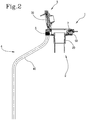
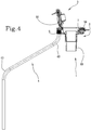
- the detection device 4 is rod-shaped and rectilinear, but there can be versions, which are shown in Figures 2-4 , in which the device, while remaining elongated-shaped, is, however, provided with at least one curved portion 40, 41, 42, 43.
- the latter can be parallel to the central axis of the base 2 of the cap, that is, parallel to the direction of introduction of the liquid, or oblique with respect to this axis, as shown in Figure 1 .
- the detection device 4 can be equipped with at least one flexible portion and configured to maintain the shape in which it has been brought, each time, following bending or straightening.
- the sensor can also include a connection module 62 connected to the first processing unit 61 and suitable for transmitting the level signal to the transmission means 8 cited above.
- inventions can be identical to one or more of the embodiments described previously, except for the fact that they are equipped with a detection device 4' that is suitable for detecting the level of the liquid in the tank without contact, that is, remotely.
Landscapes
- Engineering & Computer Science (AREA)
- Sustainable Energy (AREA)
- Life Sciences & Earth Sciences (AREA)
- Sustainable Development (AREA)
- Chemical & Material Sciences (AREA)
- Combustion & Propulsion (AREA)
- Transportation (AREA)
- Mechanical Engineering (AREA)
- General Physics & Mathematics (AREA)
- Fluid Mechanics (AREA)
- Physics & Mathematics (AREA)
- Measurement Of Levels Of Liquids Or Fluent Solid Materials (AREA)
- Cooling, Air Intake And Gas Exhaust, And Fuel Tank Arrangements In Propulsion Units (AREA)
Description
- The object of the present invention is a fuel tank cap that incorporates a level sensor.
- The invention refers particularly but not exclusively to fuel tank caps for motorcycles, caravans, current generators, etc.
- In detail, the invention has been devised mainly for motorcycle fuel tank caps that are of the "hands-free" or "keyless" type.
- Currently, road motorcycles are equipped with various electronic control devices that are connected to a central control unit located on board the vehicle.
- Some of these devices are associated with the fuel tank.
- For example, there are known hands-free caps for the fuel tanks of motorcycles and they are provided with internal control logic which makes it possible to unlock or lock the cap lock without having to insert a key in the keyhole and thus without having to "use hands".
- In detail, this control logic is connected to an antenna which is capable of transmitting and receiving signals from a transponder which is supplied to the user.
- In this manner, when the user approaches the motorcycle, the cap unlocks automatically, whereas when the user moves away from it, the cap lock locks.
- There are also known fuel tanks that are equipped with electronic level sensors to measure the remaining amount of fuel and to transmit a level signal to the control unit, which then informs the driver by means of an indicator provided on the dashboard.
- These level sensors are also equipped with their own control logic, which is contained in a seat provided in the tank for this purpose.
- The presence of this seat constitutes an encumbrance and a complication in the design and realization of the tanks, with which the manufacturer is burdened.
- Moreover, the level sensors of the known type are equipped with a rod-shaped, rectilinear detection element that must be located within the internal volume of the tanks, said internal volume being intended for containing the fuel.
- It is known that this volume is irregular in its geometry, which affects the position and angle with which the detection rod of the sensor is arranged in the tank.
- This circumstance constitutes a restriction as to the position in the tank in which the above-mentioned seat for the control logic of the level sensor can be located.
-
US9080529 -
DE102017002856 relates to a closure cap for an equalizing reservoir of a motor vehicle cooling arrangement. The closure cap includes a cap body and a fill level sensor arranged on the cap body. The fill level sensor enables the fill level of the coolant inside the equalizing reservoir to be measured. The cap body may be disposed removably on the equalizing reservoir and closes off a filling opening of the equalizing reservoir. -
EP1920965 describes a monitoring apparatus for tanks and the like, comprising detecting means to detect the filling level of a tank, detecting means to detect the opened and closed states of opening/closing means of said tank, and gathering and processing means to gather and process the detected data. The processing means are integrated with an RFID unit which can communicate said data with a remote transceiver unit. -
DE202006018622 discloses a gauge having a capacitive sensor that is arranged in such a manner to be immersed into liquid in a tank and the capacitance of the sensor changes according to the level of the liquid in the tank. - The technical task underlying the present invention is thus to propose a fuel tank cap that overcomes the limits of the prior art.
- This technical task is achieved by the assembly realized by the cap according to
claim 1. - Further characteristics and advantages of the present invention will become more apparent from the following indicative and thus non-limiting description of a preferred, but not exclusive, embodiments of a cap of the invention, as illustrated in the appended drawings, of which:
-
Figures 1-4 and7 are sectional side views of the proposed cap, equipped with level detection devices for detecting the level of the liquid and having different configurations; and -
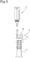
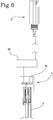
Figures 5 and6 are schematic drawings of two versions of a level sensor used in the proposed cap. - With reference to the figures cited, a fuel tank cap according to the invention is indicated by the
number 1. - Although the
cap 1 has been especially designed to be applied to the fuel tanks of motor vehicles, it can, however, being used in any type of tank, that is, a tank not necessarily intended to contain fuel. - The proposed
cap 1 includes anattachment base 2 which can be for example annular-shapep and intended to be fixed to the mouth of the tank. In detail, thecap 1 can comprise aflap 3, for example a flap hinged to thebase 2, and adapted to close/open an access defined at the centre of thebase 2. - Both the
base 2 and theflap 3 include a relative component defined by a metal and/or plastic body, the characteristics of which will be defined in detail below. - A lock for locking/unlocking the
flap 3 to/from the annular body can also be provided. - The proposed
cap 1 integrates anelectronic level sensor detection device 4 for detecting the level of liquids, which, when in use, extends in the internal volume of the tank. - In practice, this
detection device 4, 4' is the sensitive element of the sensor and it can be electromechanically operated, and for example equipped with a float, or it can be electronically operated and suitable for example for detecting variations in impedance or variations of the magnetic field; furthermore, the detection device 4'can be configured to determine the level of the liquid without contact, according to procedures described herein below. - The level sensor, 4, 4', 6 can also be of the known type as such, although some advantageous optional aspects that are not found in sensors of the prior art shall be described herein below.
- The
sensor electronic control unit 61 configured to transmit at the output a level signal as a function of the detection carried out by thedevice 4, 4'. - According to an important aspect of the invention, the
cap 1 comprises a firstinternal seat 5 in which thefirst control unit 61 is housed. - As can be seen in the figures, this
first seat 5 is provided in thecontainment body 20 of thebase 2 of thecap 1. In an embodiment (not according to the invention) it can be alternatively included in thestructural body 30 of the cover. - Especially in the case of application of the proposed
cap 1 to a motorcycle tank, it can be envisaged that it be configured to be hands-free or keyless, in the sense already explained in the description of the prior art. - In this case, the
cap 1 comprises an electronically activated lock and a secondelectronic control unit 7 configured to control the lock. - Advantageously, the
second unit 7 is housed in asecond seat 50 obtained within thebody 20 of thebase 2 or within thebody 30 of theflap 3. - Preferably, the first and the
second seat - In the illustrated example, the first and the
second seat body 20 of thebase 2 of thecap 1. - In detail, the two
seats base 2 of thecap 1. - In an alternative embodiment, which is not illustrated, it can be envisaged that both the first and the
second control unit - In this case, the two processing units could be integrated to one another so as to define a single electronic control module.
- According to additional different embodiments not according to the invention, one of the two
units base 2 or they could both be contained in thecover 3. - The
cap 1 can be equipped with transmission means for transmittingoutput signals 8 directed in particular to an external electronic control unit and said means is constituted for example by one or more cables. - Preferably, this transmission means 8 carries both said level signal and the signals transmitted by the
second processing unit 7. - A plurality of embodiments of the invention characterized by possible configurations of the above-mentioned
detection device 4 of the level sensor shall now be described. - In the example shown in
Figure 1 , thedetection device 4 is rod-shaped and rectilinear, but there can be versions, which are shown inFigures 2-4 , in which the device, while remaining elongated-shaped, is, however, provided with at least onecurved portion - In the case of a
rectilinear device 4, the latter can be parallel to the central axis of thebase 2 of the cap, that is, parallel to the direction of introduction of the liquid, or oblique with respect to this axis, as shown inFigure 1 . - To be precise, the invention can envisage that the
detection device 4 is formed of a plurality of sections that can be joined to one another in correspondence of at least one of the ends. - In this case, the
detection device 4 is modular and it can be composed differently according to specific needs; therefore, the device is defined by many longitudinal segments, or sections, which can be straight or curved and have different curvatures and lengths. - Alternatively or additionally, the
detection device 4 can be equipped with at least one flexible portion and configured to maintain the shape in which it has been brought, each time, following bending or straightening. - Furthermore, the sensor can include an
upper head 6 that comprises saidfirst processing unit 61, which is directly connected to thedetection device 4. - The sensor can also include a
connection module 62 connected to thefirst processing unit 61 and suitable for transmitting the level signal to the transmission means 8 cited above. - In the embodiment shown in
Figure 5 , theconnection module 62 is included in the above-mentionedhead 6 of the sensor that is placed at thefirst seat 5 cited above. - In the version shown in
Figure 6 , theconnection module 62 is separated from thehead 6 of the sensor and it is placed for example at the same connectors of thesecond processing unit 7, that is, the one controlling the lock for thecap 1. - Further embodiments of the invention shall now be described with the aid of
Figure 7 . - These embodiments can be identical to one or more of the embodiments described previously, except for the fact that they are equipped with a detection device 4' that is suitable for detecting the level of the liquid in the tank without contact, that is, remotely.
- In detail, the detection device 4' can be suitable for emitting a signal towards the surface of the liquid and for receiving the signal that is reflected by the same liquid.
- In this case, the emitter/receiver of the detection device 4' faces the liquid, that is, it generally faces downwards or in any case towards the internal part of the tank to which the
cap 1 is applied. - In this embodiment, the
first processing unit 61 is configured to calculate the distance between the liquid and the detection device 4', as a function of the so-called "time of flight", that is, the time between the emission of the starting signal and the reception of the reflected signal, and as a function of the propagation velocity in the means in which the signal travels, which is generally the air. - The detection device 4' can be suitable for emitting and receiving an optical signal, for example of a laser or infrared or other type.
- Alternatively or additionally, the detection device 4' is suitable for emitting a signal of an acoustic type, for example ultrasounds.
- It is therefore clearly seen that the invention not only overcomes all of the drawbacks of the prior art concerning the encumbrance of the level sensor and the restrictions imposed on manufacturers, but it also advantageously makes it possible to adapt the shape of the
detection device 4 to the geometry of the internal volume of the specific tank on which thecap 1 is applied.
Claims (14)
- A tank cap (1) comprising a containment body (20) and including an electronic level sensor (4, 6) that comprises a detection device (4,4') for detecting the level of liquids and a first electronic control unit (61) configured to transmit a level signal as a function of the detection carried out by said device (4, 4'), said body (20) is comprised in an annular base (2) defining a central access and adapted to be fixed to the mouth of a tank, characterized in that said first control unit (61) is housed in a first seat (5) comprised in said containment body (20), the tank cap (1) further comprising a flap (3) suitable for closing said central access.
- The tank cap (1) according to at least one of the preceding claims, wherein said detection device (4) is suitable for detecting variations in impedance and/or variations of the magnetic field.
- The tank cap (1) according to at least one of the preceding claims, comprising an electronically activated lock and a second electronic control unit (7) configured to control said lock, housed in a second seat (50) obtained within the above-mentioned body (20).
- The tank cap (1) according to the preceding claim, wherein the first and the second seat (5, 50) are located in diametrically opposed positions of the containing body (20).
- The tank cap (1) according to the preceding claim, wherein the first and the second seat coincide.
- The tank cap (1) according to at least one of claims 3 to 5, wherein the first and the second control unit are integrated with each other.
- The tank cap (1) according to at least one of the preceding claims, wherein said detection device (4) is rod-shaped.
- The tank cap (1) according to at least one of claims 1 - 6, wherein said detection device (4) is elongated and includes at least one curved portion (40, 41, 42, 43).
- The tank cap (1) according to the preceding claim, wherein the detection device is formed of a plurality of sections that can be joined one an in correspondence of at least one of the ends, wherein at least one of the sections is curved.
- The tank cap (1) according to at least one of claims 1 - 9, wherein the detection device is flexible.
- The tank cap (1) according to claim 1, wherein the detection device (4') is suitable for detecting the level of a liquid without contact with the latter.
- The tank cap (1) according to the preceding claim, wherein the detection device (4') is suitable for emitting a signal and for receiving a signal reflected by said liquid.
- The tank cap (1) according to the preceding claim, wherein the detection device (4') is suitable for emitting and receiving a signal of an optical type.
- The tank cap (1) according to claim 12, wherein the detection device (4') is suitable for emitting and receiving a signal of the acoustic type.
Priority Applications (2)
| Application Number | Priority Date | Filing Date | Title |
|---|---|---|---|
| PT181721820T PT3569435T (en) | 2018-05-14 | 2018-05-14 | Fuel tank cap |
| EP18172182.0A EP3569435B1 (en) | 2018-05-14 | 2018-05-14 | Fuel tank cap |
Applications Claiming Priority (1)
| Application Number | Priority Date | Filing Date | Title |
|---|---|---|---|
| EP18172182.0A EP3569435B1 (en) | 2018-05-14 | 2018-05-14 | Fuel tank cap |
Publications (2)
| Publication Number | Publication Date |
|---|---|
| EP3569435A1 EP3569435A1 (en) | 2019-11-20 |
| EP3569435B1 true EP3569435B1 (en) | 2022-01-05 |
Family
ID=62567205
Family Applications (1)
| Application Number | Title | Priority Date | Filing Date |
|---|---|---|---|
| EP18172182.0A Active EP3569435B1 (en) | 2018-05-14 | 2018-05-14 | Fuel tank cap |
Country Status (2)
| Country | Link |
|---|---|
| EP (1) | EP3569435B1 (en) |
| PT (1) | PT3569435T (en) |
Families Citing this family (2)
| Publication number | Priority date | Publication date | Assignee | Title |
|---|---|---|---|---|
| DE102019101465A1 (en) * | 2019-01-22 | 2020-07-23 | Bayerische Motoren Werke Aktiengesellschaft | Modular fuel cap system |
| CN116330967A (en) * | 2022-12-27 | 2023-06-27 | 麦克传感器股份有限公司 | A kind of automobile oil tank cover that can be installed with sensor |
Citations (1)
| Publication number | Priority date | Publication date | Assignee | Title |
|---|---|---|---|---|
| US7053782B2 (en) * | 2003-08-26 | 2006-05-30 | Yamaha Marine Kabushiki Kaisha | Fuel overflow alarm system |
Family Cites Families (5)
| Publication number | Priority date | Publication date | Assignee | Title |
|---|---|---|---|---|
| EP1920965B1 (en) * | 2006-11-10 | 2011-06-29 | MONTALBANO TECHNOLOGY S.p.A. | Monitoring apparatus for tanks and the like |
| DE202006018622U1 (en) * | 2006-12-04 | 2007-02-15 | Raber, Wolfgang | Electronic gague for measuring liquid e.g. fuel, level in tank, has capacitive sensor that is arranged such that it is immersed into liquid in tank and its capacitance changes according to level of liquid in tank |
| US9080529B1 (en) * | 2011-07-25 | 2015-07-14 | Kevin Mark Klughart | Fuel management fuel surcharge system and method |
| US9533568B1 (en) * | 2015-10-14 | 2017-01-03 | George Anthony Harvey | Method and apparatus for anti-siphoning of fuel |
| DE102017002856A1 (en) * | 2017-03-24 | 2018-09-27 | GM Global Technology Operations LLC (n. d. Ges. d. Staates Delaware) | Expansion tank with level sensor |
-
2018
- 2018-05-14 PT PT181721820T patent/PT3569435T/en unknown
- 2018-05-14 EP EP18172182.0A patent/EP3569435B1/en active Active
Patent Citations (1)
| Publication number | Priority date | Publication date | Assignee | Title |
|---|---|---|---|---|
| US7053782B2 (en) * | 2003-08-26 | 2006-05-30 | Yamaha Marine Kabushiki Kaisha | Fuel overflow alarm system |
Also Published As
| Publication number | Publication date |
|---|---|
| PT3569435T (en) | 2022-03-28 |
| EP3569435A1 (en) | 2019-11-20 |
Similar Documents
| Publication | Publication Date | Title |
|---|---|---|
| US8571725B2 (en) | Apparatus for locating a vehicle electronic key | |
| US6577228B1 (en) | Door handle for vehicle and smart entry system for vehicle using the same | |
| US10099655B2 (en) | Wheel fastener alarm | |
| US6218932B1 (en) | Antitheft device for a motor vehicle and method for operating the antitheft device | |
| US10662682B2 (en) | Access system for a vehicle | |
| JP3566943B2 (en) | Vehicle door handle | |
| KR20210020814A (en) | Method for door or flap operation in vehicle, authentication element and vehicle | |
| EP3569435B1 (en) | Fuel tank cap | |
| JP3714129B2 (en) | Door opener | |
| US20090212978A1 (en) | System for managing a fleet of automotive vehicles | |
| KR20170007127A (en) | Device for detecting a user's intention to lock or unlock a motor vehicle door | |
| US6647773B2 (en) | System and method for integrated tire pressure monitoring and passive entry | |
| US20080068128A1 (en) | Keyless passive entry system | |
| CN103366430A (en) | Access arrangement for vehicle | |
| EP1632410B1 (en) | Smart key system | |
| JP2014084595A (en) | Key position determination device | |
| US20060011164A1 (en) | Vehicle fueling arrangement | |
| CN104736398A (en) | Method and device for determining a distance and for actuating a closing element of a vehicle | |
| WO2008131813A1 (en) | An easy-to-use access control system | |
| US20190001812A1 (en) | Pre-consumption fuel analytics system | |
| EP3225959B1 (en) | Device for determining liquid level in a container | |
| JP2002295064A (en) | Door opening and closing device | |
| JP5812820B2 (en) | Key-free system | |
| US20210039588A1 (en) | Wheel fastener alarm | |
| CN206957383U (en) | A kind of Multifunctional bicycle Fingerprint Lock |
Legal Events
| Date | Code | Title | Description |
|---|---|---|---|
| PUAI | Public reference made under article 153(3) epc to a published international application that has entered the european phase |
Free format text: ORIGINAL CODE: 0009012 |
|
| STAA | Information on the status of an ep patent application or granted ep patent |
Free format text: STATUS: THE APPLICATION HAS BEEN PUBLISHED |
|
| AK | Designated contracting states |
Kind code of ref document: A1 Designated state(s): AL AT BE BG CH CY CZ DE DK EE ES FI FR GB GR HR HU IE IS IT LI LT LU LV MC MK MT NL NO PL PT RO RS SE SI SK SM TR |
|
| AX | Request for extension of the european patent |
Extension state: BA ME |
|
| STAA | Information on the status of an ep patent application or granted ep patent |
Free format text: STATUS: REQUEST FOR EXAMINATION WAS MADE |
|
| 17P | Request for examination filed |
Effective date: 20200806 |
|
| RBV | Designated contracting states (corrected) |
Designated state(s): AL AT BE BG CH CY CZ DE DK EE ES FI FR GB GR HR HU IE IS IT LI LT LU LV MC MK MT NL NO PL PT RO RS SE SI SK SM TR |
|
| STAA | Information on the status of an ep patent application or granted ep patent |
Free format text: STATUS: EXAMINATION IS IN PROGRESS |
|
| 17Q | First examination report despatched |
Effective date: 20210113 |
|
| GRAP | Despatch of communication of intention to grant a patent |
Free format text: ORIGINAL CODE: EPIDOSNIGR1 |
|
| STAA | Information on the status of an ep patent application or granted ep patent |
Free format text: STATUS: GRANT OF PATENT IS INTENDED |
|
| INTG | Intention to grant announced |
Effective date: 20211005 |
|
| GRAS | Grant fee paid |
Free format text: ORIGINAL CODE: EPIDOSNIGR3 |
|
| GRAA | (expected) grant |
Free format text: ORIGINAL CODE: 0009210 |
|
| STAA | Information on the status of an ep patent application or granted ep patent |
Free format text: STATUS: THE PATENT HAS BEEN GRANTED |
|
| AK | Designated contracting states |
Kind code of ref document: B1 Designated state(s): AL AT BE BG CH CY CZ DE DK EE ES FI FR GB GR HR HU IE IS IT LI LT LU LV MC MK MT NL NO PL PT RO RS SE SI SK SM TR |
|
| REG | Reference to a national code |
Ref country code: GB Ref legal event code: FG4D |
|
| REG | Reference to a national code |
Ref country code: CH Ref legal event code: EP |
|
| REG | Reference to a national code |
Ref country code: AT Ref legal event code: REF Ref document number: 1460224 Country of ref document: AT Kind code of ref document: T Effective date: 20220115 |
|
| REG | Reference to a national code |
Ref country code: DE Ref legal event code: R096 Ref document number: 602018029000 Country of ref document: DE |
|
| REG | Reference to a national code |
Ref country code: IE Ref legal event code: FG4D |
|
| REG | Reference to a national code |
Ref country code: PT Ref legal event code: SC4A Ref document number: 3569435 Country of ref document: PT Date of ref document: 20220328 Kind code of ref document: T Free format text: AVAILABILITY OF NATIONAL TRANSLATION Effective date: 20220321 |
|
| REG | Reference to a national code |
Ref country code: LT Ref legal event code: MG9D |
|
| REG | Reference to a national code |
Ref country code: NL Ref legal event code: MP Effective date: 20220105 |
|
| REG | Reference to a national code |
Ref country code: DE Ref legal event code: R081 Ref document number: 602018029000 Country of ref document: DE Owner name: CEV LAB S.R.L., IT Free format text: FORMER OWNER: CEV LAB S.R.L. CON UNICO SOCIO, LAINATE, IT |
|
| PG25 | Lapsed in a contracting state [announced via postgrant information from national office to epo] |
Ref country code: NL Free format text: LAPSE BECAUSE OF FAILURE TO SUBMIT A TRANSLATION OF THE DESCRIPTION OR TO PAY THE FEE WITHIN THE PRESCRIBED TIME-LIMIT Effective date: 20220105 |
|
| PG25 | Lapsed in a contracting state [announced via postgrant information from national office to epo] |
Ref country code: SE Free format text: LAPSE BECAUSE OF FAILURE TO SUBMIT A TRANSLATION OF THE DESCRIPTION OR TO PAY THE FEE WITHIN THE PRESCRIBED TIME-LIMIT Effective date: 20220105 Ref country code: RS Free format text: LAPSE BECAUSE OF FAILURE TO SUBMIT A TRANSLATION OF THE DESCRIPTION OR TO PAY THE FEE WITHIN THE PRESCRIBED TIME-LIMIT Effective date: 20220105 Ref country code: NO Free format text: LAPSE BECAUSE OF FAILURE TO SUBMIT A TRANSLATION OF THE DESCRIPTION OR TO PAY THE FEE WITHIN THE PRESCRIBED TIME-LIMIT Effective date: 20220405 Ref country code: LT Free format text: LAPSE BECAUSE OF FAILURE TO SUBMIT A TRANSLATION OF THE DESCRIPTION OR TO PAY THE FEE WITHIN THE PRESCRIBED TIME-LIMIT Effective date: 20220105 Ref country code: HR Free format text: LAPSE BECAUSE OF FAILURE TO SUBMIT A TRANSLATION OF THE DESCRIPTION OR TO PAY THE FEE WITHIN THE PRESCRIBED TIME-LIMIT Effective date: 20220105 Ref country code: ES Free format text: LAPSE BECAUSE OF FAILURE TO SUBMIT A TRANSLATION OF THE DESCRIPTION OR TO PAY THE FEE WITHIN THE PRESCRIBED TIME-LIMIT Effective date: 20220105 Ref country code: BG Free format text: LAPSE BECAUSE OF FAILURE TO SUBMIT A TRANSLATION OF THE DESCRIPTION OR TO PAY THE FEE WITHIN THE PRESCRIBED TIME-LIMIT Effective date: 20220405 |
|
| PG25 | Lapsed in a contracting state [announced via postgrant information from national office to epo] |
Ref country code: PL Free format text: LAPSE BECAUSE OF FAILURE TO SUBMIT A TRANSLATION OF THE DESCRIPTION OR TO PAY THE FEE WITHIN THE PRESCRIBED TIME-LIMIT Effective date: 20220105 Ref country code: LV Free format text: LAPSE BECAUSE OF FAILURE TO SUBMIT A TRANSLATION OF THE DESCRIPTION OR TO PAY THE FEE WITHIN THE PRESCRIBED TIME-LIMIT Effective date: 20220105 Ref country code: GR Free format text: LAPSE BECAUSE OF FAILURE TO SUBMIT A TRANSLATION OF THE DESCRIPTION OR TO PAY THE FEE WITHIN THE PRESCRIBED TIME-LIMIT Effective date: 20220406 Ref country code: FI Free format text: LAPSE BECAUSE OF FAILURE TO SUBMIT A TRANSLATION OF THE DESCRIPTION OR TO PAY THE FEE WITHIN THE PRESCRIBED TIME-LIMIT Effective date: 20220105 |
|
| PG25 | Lapsed in a contracting state [announced via postgrant information from national office to epo] |
Ref country code: IS Free format text: LAPSE BECAUSE OF FAILURE TO SUBMIT A TRANSLATION OF THE DESCRIPTION OR TO PAY THE FEE WITHIN THE PRESCRIBED TIME-LIMIT Effective date: 20220505 |
|
| REG | Reference to a national code |
Ref country code: DE Ref legal event code: R097 Ref document number: 602018029000 Country of ref document: DE |
|
| PG25 | Lapsed in a contracting state [announced via postgrant information from national office to epo] |
Ref country code: SM Free format text: LAPSE BECAUSE OF FAILURE TO SUBMIT A TRANSLATION OF THE DESCRIPTION OR TO PAY THE FEE WITHIN THE PRESCRIBED TIME-LIMIT Effective date: 20220105 Ref country code: SK Free format text: LAPSE BECAUSE OF FAILURE TO SUBMIT A TRANSLATION OF THE DESCRIPTION OR TO PAY THE FEE WITHIN THE PRESCRIBED TIME-LIMIT Effective date: 20220105 Ref country code: RO Free format text: LAPSE BECAUSE OF FAILURE TO SUBMIT A TRANSLATION OF THE DESCRIPTION OR TO PAY THE FEE WITHIN THE PRESCRIBED TIME-LIMIT Effective date: 20220105 Ref country code: EE Free format text: LAPSE BECAUSE OF FAILURE TO SUBMIT A TRANSLATION OF THE DESCRIPTION OR TO PAY THE FEE WITHIN THE PRESCRIBED TIME-LIMIT Effective date: 20220105 Ref country code: DK Free format text: LAPSE BECAUSE OF FAILURE TO SUBMIT A TRANSLATION OF THE DESCRIPTION OR TO PAY THE FEE WITHIN THE PRESCRIBED TIME-LIMIT Effective date: 20220105 Ref country code: CZ Free format text: LAPSE BECAUSE OF FAILURE TO SUBMIT A TRANSLATION OF THE DESCRIPTION OR TO PAY THE FEE WITHIN THE PRESCRIBED TIME-LIMIT Effective date: 20220105 |
|
| PLBE | No opposition filed within time limit |
Free format text: ORIGINAL CODE: 0009261 |
|
| STAA | Information on the status of an ep patent application or granted ep patent |
Free format text: STATUS: NO OPPOSITION FILED WITHIN TIME LIMIT |
|
| PG25 | Lapsed in a contracting state [announced via postgrant information from national office to epo] |
Ref country code: AL Free format text: LAPSE BECAUSE OF FAILURE TO SUBMIT A TRANSLATION OF THE DESCRIPTION OR TO PAY THE FEE WITHIN THE PRESCRIBED TIME-LIMIT Effective date: 20220105 |
|
| 26N | No opposition filed |
Effective date: 20221006 |
|
| REG | Reference to a national code |
Ref country code: CH Ref legal event code: PL |
|
| REG | Reference to a national code |
Ref country code: BE Ref legal event code: MM Effective date: 20220531 |
|
| GBPC | Gb: european patent ceased through non-payment of renewal fee |
Effective date: 20220514 |
|
| PG25 | Lapsed in a contracting state [announced via postgrant information from national office to epo] |
Ref country code: MC Free format text: LAPSE BECAUSE OF FAILURE TO SUBMIT A TRANSLATION OF THE DESCRIPTION OR TO PAY THE FEE WITHIN THE PRESCRIBED TIME-LIMIT Effective date: 20220105 Ref country code: LU Free format text: LAPSE BECAUSE OF NON-PAYMENT OF DUE FEES Effective date: 20220514 Ref country code: LI Free format text: LAPSE BECAUSE OF NON-PAYMENT OF DUE FEES Effective date: 20220531 Ref country code: CH Free format text: LAPSE BECAUSE OF NON-PAYMENT OF DUE FEES Effective date: 20220531 |
|
| PG25 | Lapsed in a contracting state [announced via postgrant information from national office to epo] |
Ref country code: SI Free format text: LAPSE BECAUSE OF FAILURE TO SUBMIT A TRANSLATION OF THE DESCRIPTION OR TO PAY THE FEE WITHIN THE PRESCRIBED TIME-LIMIT Effective date: 20220105 |
|
| PG25 | Lapsed in a contracting state [announced via postgrant information from national office to epo] |
Ref country code: IE Free format text: LAPSE BECAUSE OF NON-PAYMENT OF DUE FEES Effective date: 20220514 |
|
| PG25 | Lapsed in a contracting state [announced via postgrant information from national office to epo] |
Ref country code: GB Free format text: LAPSE BECAUSE OF NON-PAYMENT OF DUE FEES Effective date: 20220514 Ref country code: BE Free format text: LAPSE BECAUSE OF NON-PAYMENT OF DUE FEES Effective date: 20220531 |
|
| P01 | Opt-out of the competence of the unified patent court (upc) registered |
Effective date: 20230601 |
|
| REG | Reference to a national code |
Ref country code: AT Ref legal event code: UEP Ref document number: 1460224 Country of ref document: AT Kind code of ref document: T Effective date: 20220105 |
|
| PG25 | Lapsed in a contracting state [announced via postgrant information from national office to epo] |
Ref country code: HU Free format text: LAPSE BECAUSE OF FAILURE TO SUBMIT A TRANSLATION OF THE DESCRIPTION OR TO PAY THE FEE WITHIN THE PRESCRIBED TIME-LIMIT; INVALID AB INITIO Effective date: 20180514 |
|
| PG25 | Lapsed in a contracting state [announced via postgrant information from national office to epo] |
Ref country code: MK Free format text: LAPSE BECAUSE OF FAILURE TO SUBMIT A TRANSLATION OF THE DESCRIPTION OR TO PAY THE FEE WITHIN THE PRESCRIBED TIME-LIMIT Effective date: 20220105 Ref country code: CY Free format text: LAPSE BECAUSE OF FAILURE TO SUBMIT A TRANSLATION OF THE DESCRIPTION OR TO PAY THE FEE WITHIN THE PRESCRIBED TIME-LIMIT Effective date: 20220105 |
|
| PG25 | Lapsed in a contracting state [announced via postgrant information from national office to epo] |
Ref country code: MT Free format text: LAPSE BECAUSE OF FAILURE TO SUBMIT A TRANSLATION OF THE DESCRIPTION OR TO PAY THE FEE WITHIN THE PRESCRIBED TIME-LIMIT Effective date: 20220105 |
|
| PGFP | Annual fee paid to national office [announced via postgrant information from national office to epo] |
Ref country code: DE Payment date: 20250528 Year of fee payment: 8 |
|
| PGFP | Annual fee paid to national office [announced via postgrant information from national office to epo] |
Ref country code: IT Payment date: 20250529 Year of fee payment: 8 |
|
| PGFP | Annual fee paid to national office [announced via postgrant information from national office to epo] |
Ref country code: PT Payment date: 20250414 Year of fee payment: 8 |
|
| PGFP | Annual fee paid to national office [announced via postgrant information from national office to epo] |
Ref country code: FR Payment date: 20250526 Year of fee payment: 8 |
|
| PGFP | Annual fee paid to national office [announced via postgrant information from national office to epo] |
Ref country code: AT Payment date: 20250520 Year of fee payment: 8 |
|
| PG25 | Lapsed in a contracting state [announced via postgrant information from national office to epo] |
Ref country code: TR Free format text: LAPSE BECAUSE OF FAILURE TO SUBMIT A TRANSLATION OF THE DESCRIPTION OR TO PAY THE FEE WITHIN THE PRESCRIBED TIME-LIMIT Effective date: 20220105 |