EP3569193A1 - Expandable breast implant - Google Patents
Expandable breast implant Download PDFInfo
- Publication number
- EP3569193A1 EP3569193A1 EP19174906.8A EP19174906A EP3569193A1 EP 3569193 A1 EP3569193 A1 EP 3569193A1 EP 19174906 A EP19174906 A EP 19174906A EP 3569193 A1 EP3569193 A1 EP 3569193A1
- Authority
- EP
- European Patent Office
- Prior art keywords
- reagent
- matrix
- cells
- expandable implant
- implant
- Prior art date
- Legal status (The legal status is an assumption and is not a legal conclusion. Google has not performed a legal analysis and makes no representation as to the accuracy of the status listed.)
- Withdrawn
Links
Images



Classifications
-
- A—HUMAN NECESSITIES
- A61—MEDICAL OR VETERINARY SCIENCE; HYGIENE
- A61F—FILTERS IMPLANTABLE INTO BLOOD VESSELS; PROSTHESES; DEVICES PROVIDING PATENCY TO, OR PREVENTING COLLAPSING OF, TUBULAR STRUCTURES OF THE BODY, e.g. STENTS; ORTHOPAEDIC, NURSING OR CONTRACEPTIVE DEVICES; FOMENTATION; TREATMENT OR PROTECTION OF EYES OR EARS; BANDAGES, DRESSINGS OR ABSORBENT PADS; FIRST-AID KITS
- A61F2/00—Filters implantable into blood vessels; Prostheses, i.e. artificial substitutes or replacements for parts of the body; Appliances for connecting them with the body; Devices providing patency to, or preventing collapsing of, tubular structures of the body, e.g. stents
- A61F2/02—Prostheses implantable into the body
- A61F2/12—Mammary prostheses
-
- A—HUMAN NECESSITIES
- A61—MEDICAL OR VETERINARY SCIENCE; HYGIENE
- A61L—METHODS OR APPARATUS FOR STERILISING MATERIALS OR OBJECTS IN GENERAL; DISINFECTION, STERILISATION OR DEODORISATION OF AIR; CHEMICAL ASPECTS OF BANDAGES, DRESSINGS, ABSORBENT PADS OR SURGICAL ARTICLES; MATERIALS FOR BANDAGES, DRESSINGS, ABSORBENT PADS OR SURGICAL ARTICLES
- A61L27/00—Materials for grafts or prostheses or for coating grafts or prostheses
- A61L27/02—Inorganic materials
- A61L27/025—Other specific inorganic materials not covered by A61L27/04 - A61L27/12
-
- A—HUMAN NECESSITIES
- A61—MEDICAL OR VETERINARY SCIENCE; HYGIENE
- A61L—METHODS OR APPARATUS FOR STERILISING MATERIALS OR OBJECTS IN GENERAL; DISINFECTION, STERILISATION OR DEODORISATION OF AIR; CHEMICAL ASPECTS OF BANDAGES, DRESSINGS, ABSORBENT PADS OR SURGICAL ARTICLES; MATERIALS FOR BANDAGES, DRESSINGS, ABSORBENT PADS OR SURGICAL ARTICLES
- A61L27/00—Materials for grafts or prostheses or for coating grafts or prostheses
- A61L27/14—Macromolecular materials
- A61L27/18—Macromolecular materials obtained otherwise than by reactions only involving carbon-to-carbon unsaturated bonds
-
- A—HUMAN NECESSITIES
- A61—MEDICAL OR VETERINARY SCIENCE; HYGIENE
- A61L—METHODS OR APPARATUS FOR STERILISING MATERIALS OR OBJECTS IN GENERAL; DISINFECTION, STERILISATION OR DEODORISATION OF AIR; CHEMICAL ASPECTS OF BANDAGES, DRESSINGS, ABSORBENT PADS OR SURGICAL ARTICLES; MATERIALS FOR BANDAGES, DRESSINGS, ABSORBENT PADS OR SURGICAL ARTICLES
- A61L27/00—Materials for grafts or prostheses or for coating grafts or prostheses
- A61L27/28—Materials for coating prostheses
-
- G—PHYSICS
- G16—INFORMATION AND COMMUNICATION TECHNOLOGY [ICT] SPECIALLY ADAPTED FOR SPECIFIC APPLICATION FIELDS
- G16H—HEALTHCARE INFORMATICS, i.e. INFORMATION AND COMMUNICATION TECHNOLOGY [ICT] SPECIALLY ADAPTED FOR THE HANDLING OR PROCESSING OF MEDICAL OR HEALTHCARE DATA
- G16H40/00—ICT specially adapted for the management or administration of healthcare resources or facilities; ICT specially adapted for the management or operation of medical equipment or devices
- G16H40/60—ICT specially adapted for the management or administration of healthcare resources or facilities; ICT specially adapted for the management or operation of medical equipment or devices for the operation of medical equipment or devices
- G16H40/67—ICT specially adapted for the management or administration of healthcare resources or facilities; ICT specially adapted for the management or operation of medical equipment or devices for the operation of medical equipment or devices for remote operation
-
- A—HUMAN NECESSITIES
- A61—MEDICAL OR VETERINARY SCIENCE; HYGIENE
- A61B—DIAGNOSIS; SURGERY; IDENTIFICATION
- A61B17/00—Surgical instruments, devices or methods
- A61B2017/00017—Electrical control of surgical instruments
- A61B2017/00022—Sensing or detecting at the treatment site
-
- A—HUMAN NECESSITIES
- A61—MEDICAL OR VETERINARY SCIENCE; HYGIENE
- A61B—DIAGNOSIS; SURGERY; IDENTIFICATION
- A61B17/00—Surgical instruments, devices or methods
- A61B2017/00017—Electrical control of surgical instruments
- A61B2017/00212—Electrical control of surgical instruments using remote controls
-
- A—HUMAN NECESSITIES
- A61—MEDICAL OR VETERINARY SCIENCE; HYGIENE
- A61B—DIAGNOSIS; SURGERY; IDENTIFICATION
- A61B17/00—Surgical instruments, devices or methods
- A61B2017/00017—Electrical control of surgical instruments
- A61B2017/00221—Electrical control of surgical instruments with wireless transmission of data, e.g. by infrared radiation or radiowaves
-
- A—HUMAN NECESSITIES
- A61—MEDICAL OR VETERINARY SCIENCE; HYGIENE
- A61F—FILTERS IMPLANTABLE INTO BLOOD VESSELS; PROSTHESES; DEVICES PROVIDING PATENCY TO, OR PREVENTING COLLAPSING OF, TUBULAR STRUCTURES OF THE BODY, e.g. STENTS; ORTHOPAEDIC, NURSING OR CONTRACEPTIVE DEVICES; FOMENTATION; TREATMENT OR PROTECTION OF EYES OR EARS; BANDAGES, DRESSINGS OR ABSORBENT PADS; FIRST-AID KITS
- A61F2210/00—Particular material properties of prostheses classified in groups A61F2/00 - A61F2/26 or A61F2/82 or A61F9/00 or A61F11/00 or subgroups thereof
- A61F2210/0076—Particular material properties of prostheses classified in groups A61F2/00 - A61F2/26 or A61F2/82 or A61F9/00 or A61F11/00 or subgroups thereof multilayered, e.g. laminated structures
-
- A—HUMAN NECESSITIES
- A61—MEDICAL OR VETERINARY SCIENCE; HYGIENE
- A61F—FILTERS IMPLANTABLE INTO BLOOD VESSELS; PROSTHESES; DEVICES PROVIDING PATENCY TO, OR PREVENTING COLLAPSING OF, TUBULAR STRUCTURES OF THE BODY, e.g. STENTS; ORTHOPAEDIC, NURSING OR CONTRACEPTIVE DEVICES; FOMENTATION; TREATMENT OR PROTECTION OF EYES OR EARS; BANDAGES, DRESSINGS OR ABSORBENT PADS; FIRST-AID KITS
- A61F2230/00—Geometry of prostheses classified in groups A61F2/00 - A61F2/26 or A61F2/82 or A61F9/00 or A61F11/00 or subgroups thereof
- A61F2230/0002—Two-dimensional shapes, e.g. cross-sections
- A61F2230/0017—Angular shapes
- A61F2230/0026—Angular shapes trapezoidal
-
- A—HUMAN NECESSITIES
- A61—MEDICAL OR VETERINARY SCIENCE; HYGIENE
- A61F—FILTERS IMPLANTABLE INTO BLOOD VESSELS; PROSTHESES; DEVICES PROVIDING PATENCY TO, OR PREVENTING COLLAPSING OF, TUBULAR STRUCTURES OF THE BODY, e.g. STENTS; ORTHOPAEDIC, NURSING OR CONTRACEPTIVE DEVICES; FOMENTATION; TREATMENT OR PROTECTION OF EYES OR EARS; BANDAGES, DRESSINGS OR ABSORBENT PADS; FIRST-AID KITS
- A61F2250/00—Special features of prostheses classified in groups A61F2/00 - A61F2/26 or A61F2/82 or A61F9/00 or A61F11/00 or subgroups thereof
- A61F2250/0001—Means for transferring electromagnetic energy to implants
- A61F2250/0002—Means for transferring electromagnetic energy to implants for data transfer
-
- A—HUMAN NECESSITIES
- A61—MEDICAL OR VETERINARY SCIENCE; HYGIENE
- A61F—FILTERS IMPLANTABLE INTO BLOOD VESSELS; PROSTHESES; DEVICES PROVIDING PATENCY TO, OR PREVENTING COLLAPSING OF, TUBULAR STRUCTURES OF THE BODY, e.g. STENTS; ORTHOPAEDIC, NURSING OR CONTRACEPTIVE DEVICES; FOMENTATION; TREATMENT OR PROTECTION OF EYES OR EARS; BANDAGES, DRESSINGS OR ABSORBENT PADS; FIRST-AID KITS
- A61F2250/00—Special features of prostheses classified in groups A61F2/00 - A61F2/26 or A61F2/82 or A61F9/00 or A61F11/00 or subgroups thereof
- A61F2250/0003—Special features of prostheses classified in groups A61F2/00 - A61F2/26 or A61F2/82 or A61F9/00 or A61F11/00 or subgroups thereof having an inflatable pocket filled with fluid, e.g. liquid or gas
-
- A—HUMAN NECESSITIES
- A61—MEDICAL OR VETERINARY SCIENCE; HYGIENE
- A61F—FILTERS IMPLANTABLE INTO BLOOD VESSELS; PROSTHESES; DEVICES PROVIDING PATENCY TO, OR PREVENTING COLLAPSING OF, TUBULAR STRUCTURES OF THE BODY, e.g. STENTS; ORTHOPAEDIC, NURSING OR CONTRACEPTIVE DEVICES; FOMENTATION; TREATMENT OR PROTECTION OF EYES OR EARS; BANDAGES, DRESSINGS OR ABSORBENT PADS; FIRST-AID KITS
- A61F2250/00—Special features of prostheses classified in groups A61F2/00 - A61F2/26 or A61F2/82 or A61F9/00 or A61F11/00 or subgroups thereof
- A61F2250/0004—Special features of prostheses classified in groups A61F2/00 - A61F2/26 or A61F2/82 or A61F9/00 or A61F11/00 or subgroups thereof adjustable
-
- A—HUMAN NECESSITIES
- A61—MEDICAL OR VETERINARY SCIENCE; HYGIENE
- A61F—FILTERS IMPLANTABLE INTO BLOOD VESSELS; PROSTHESES; DEVICES PROVIDING PATENCY TO, OR PREVENTING COLLAPSING OF, TUBULAR STRUCTURES OF THE BODY, e.g. STENTS; ORTHOPAEDIC, NURSING OR CONTRACEPTIVE DEVICES; FOMENTATION; TREATMENT OR PROTECTION OF EYES OR EARS; BANDAGES, DRESSINGS OR ABSORBENT PADS; FIRST-AID KITS
- A61F2250/00—Special features of prostheses classified in groups A61F2/00 - A61F2/26 or A61F2/82 or A61F9/00 or A61F11/00 or subgroups thereof
- A61F2250/0004—Special features of prostheses classified in groups A61F2/00 - A61F2/26 or A61F2/82 or A61F9/00 or A61F11/00 or subgroups thereof adjustable
- A61F2250/0013—Special features of prostheses classified in groups A61F2/00 - A61F2/26 or A61F2/82 or A61F9/00 or A61F11/00 or subgroups thereof adjustable for adjusting fluid pressure
-
- A—HUMAN NECESSITIES
- A61—MEDICAL OR VETERINARY SCIENCE; HYGIENE
- A61F—FILTERS IMPLANTABLE INTO BLOOD VESSELS; PROSTHESES; DEVICES PROVIDING PATENCY TO, OR PREVENTING COLLAPSING OF, TUBULAR STRUCTURES OF THE BODY, e.g. STENTS; ORTHOPAEDIC, NURSING OR CONTRACEPTIVE DEVICES; FOMENTATION; TREATMENT OR PROTECTION OF EYES OR EARS; BANDAGES, DRESSINGS OR ABSORBENT PADS; FIRST-AID KITS
- A61F2250/00—Special features of prostheses classified in groups A61F2/00 - A61F2/26 or A61F2/82 or A61F9/00 or A61F11/00 or subgroups thereof
- A61F2250/0058—Additional features; Implant or prostheses properties not otherwise provided for
- A61F2250/0096—Markers and sensors for detecting a position or changes of a position of an implant, e.g. RF sensors, ultrasound markers
Definitions
- a medical apparatus including an expandable breast implant that eliminates the need for multiple procedures and injections, with the capability for self-administered expansion that is safe in any environment.
- the expandable breast implant includes an upper matrix, a lower matrix, and a middle layer that separates the upper matrix and lower matrix.
- the upper matrix is covered by a hydrophobic membrane.
- the upper matrix comprises a plurality of cells containing a first reagent.
- the lower matrix comprises a plurality of wells containing a second reagent.
- the middle layer acts as a barrier between the upper matrix and the lower matrix. The middle layer may be activated and controlled to form openings at selected locations.
- the first reagent from the cells in the upper matrix mixes with the second reagent from the wells in the lower matrix through the selected openings in the middle layer.
- the reagents react to generate a gas, which is released through the hydrophobic membrane top of the upper matrix.
- the gas permeates the hydrophobic membrane into an expandable shell to enlarge the breast implant.
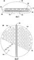
- FIG. 1 is an example cross-sectional view of a multi-layer expandable breast implant 100.
- the expandable breast implant 100 includes an expandable shell 160, an upper matrix 110, a lower matrix 130, and a middle layer 120.
- the expandable shell 160 may comprise silicone, and the shell 160 is filled with one or more different types of silicone.
- the shell may be filled with saline or another material, or even unfilled.
- the upper matrix 110 comprises a plurality of cells 105. As shown in FIG. 1 , the cells 105 may be angularly shaped with the cell 105 gradually increasing in size toward the middle layer 120. Each cell 105 contains a first reagent.
- the lower matrix 130 comprises a plurality of wells 135. Each well 135 is aligned with a complimentary cell 105. The wells 135 contain a second reagent.
- the middle layer 120 forms a barrier between the upper matrix 110 and lower matrix 130.
- the upper matrix 110, lower matrix 130, and middle layer 120 may be coupled together with glue, heat-sealing, or any other appropriate manner to form the multi-layer structure 140.
- the multi-layer structure 140 may be encased in a hydrophobic membrane 150, such that gases permeate the hydrophobic membrane 150 while liquid is denied passage.
- the hydrophobic membrane 150 covers only the top of the upper matrix 110.
- the hydrophobic membrane 150 may be coupled to the top of the upper matrix 110 via any appropriate manner such as glue, heat-sealing, or the like.
- the multi-layer structure 140 and the hydrophobic membrane 150 are further encased in an expandable shell 160 to form the expandable breast implant 100.
- the hydrophobic membrane 150 may cover the lower matrix 130, or both the upper matrix 110 and the lower matrix 130. In the event that the hydrophobic membrane 150 covers the lower matrix 130, complimentary holes would be located in the wells 135 of the lower matrix 130.
- FIG. 2 is a top view of the upper matrix 110.
- the upper matrix 110 may comprise polyurethane, rubber or silicone.
- FIG. 2 depicts a top view of the plurality of cells 105 in the upper matrix 110, which comprise openings in the top side 210 of the upper matrix 110.
- the cells 105 are shown as hexagonal in shape, the shape of the top of the cells 105 is illustrative, and those skilled in the art would understand that the cells 105 may be configured in any geometric shape that would properly accommodate the first reagent.
- the hydrophobic membrane 150 covers the entire top side 210 of the upper matrix 110. However, FIG. 2 does not show a portion of the hydrophobic membrane 150, for explanatory purposes.
- the hydrophobic membrane 150 is flexible and permits the gas that is generated to permeate through the hydrophobic membrane 150.
- the top side 210 of the upper matrix 110 may include at least one upper groove 220 to increase the pliability of the upper matrix 110.
- FIG. 2 depicts one upper groove 220 spanning the diameter of the upper matrix 110, although more than one grove may be utilized.
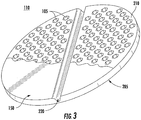
- FIG. 3 shows a perspective view of the top side 210 of the upper matrix 110 illustrating the tops of the cells 105 and the upper groove 220.
- a portion of the hydrophobic membrane 150 is not shown for simplicity.
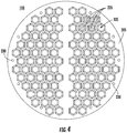
- FIG. 4 shows the bottom side 205 of the upper matrix 110.
- the bottom side 205 is configured to be in contact with the middle layer 120.
- the cells 105 are shown as hexagonal in shape. However, as aforementioned, the shape of the cells 105 is illustrative and may be in any appropriate geometric shape. As illustrated in FIG. 4 , the cells 105 may be arranged in a honeycomb pattern.
- the bottom side 205 of the upper matrix 110 may include a number of holes 230 configured to receive pegs from the lower matrix 130, in order to keep the upper matrix 110 and the lower matrix 130 properly aligned.
- the cells 105 contain a first reagent 235.
- the first reagent 235 by way of example is sodium bicarbonate.
- the first reagent 235 may fill a few cells 105 or a portion of the cells 105. However, it is most likely that most or all of the cells 105 contain the first reagent 235. In this embodiment, each cell may contain approximately 0.06g of sodium bicarbonate. However, more or less reagent, or a different reagent, may be utilized.
- FIG. 5 is an alternative embodiment of the upper matrix 110 whereby a plurality of cells 105 may be grouped together to form a larger cell, or a cell "cluster".
- cluster A is a 5 cell grouping
- cluster B is a 4 cell grouping. Any size cell or grouping may be configured, depending upon the amount of gas desired to be generated at one time.
- the cells 105 may be the shape of an inverted funnel. The inverted funnel shape of the cells 105 optimizes the mixing of the first reagent and the second reagent. The purpose and process of the mixing of the reagents will be described in greater detail hereinafter.
- FIG. 7 shows a top view of the lower matrix 130.
- the lower matrix 130 may comprise polyurethane, rubber or silicone.
- the top side 610 of the lower matrix 130 is configured to be in contact with the middle layer 120.
- the lower matrix 130 may include a number of pegs 630 that are complimentary to, and insert into, the holes 230 of the upper matrix 110.
- the hole 230 and peg 630 configuration is an optional means of coupling the upper matrix 110, lower matrix 130, and middle layer 120 together and also the membrane.
- the arrangement of the wells 135 in the lower matrix 130 should optimally match the configuration of the cells 105 in the upper matrix 110.
- the perimeter of each well 135 preferably aligns with the perimeter of a cell 105 in the upper matrix 110, although exact alignment is not required. As an example, FIG.
- FIG. 7 shows single wells 135 that align with the single cells 105 depicted in FIG. 4 .
- all wells 135 contain the second reagent 635, which may be at least 70% acetic acid depending upon the volume of the wells. However, more or less reagent, or a different reagent, may be utilized.
- the second reagent 635 is graphically illustrated as filling only a few wells 135, it is most likely that most or all of the wells 135 contain the second reagent 635.
- the first reagent 235 in the cells 105 passes through openings in the middle layer 120 and mixes with the second reagent 635 in the wells 135.
- the reagents 235, 635 mix and react to generate a gas.
- the first reagent 235 is sodium biocarbonate and the second reagent 635 is acetic acid, wherein the reaction produces carbon dioxide.
- Each cell 105 and well 135 may contain enough materials to produce 15 cc of carbon dioxide.
- FIG. 8 is a top view of the lower matrix 130 in an alternative embodiment.
- This embodiment includes one or more groupings of wells 135, comprising a plurality of wells 135 joined together to form a well "cluster."
- these wells 135 may simply comprise a larger-sized well 135.
- each well 135 cluster is configured to be generally aligned with a complimentary cell 105 in the upper matrix 110.
- the embodiment of the lower matrix 130 shown in FIG. 8 would be complimentary with the embodiment of the upper matrix 110 shown in FIG. 5 .
- the perimeter of each well 135 may be configured to overlap the same area as a cluster of cells 105 in the upper matrix 110.
- Well A is an example of a well 135 configured to accommodate a 5 cell 105 cluster
- Well B is an example of a well 135 configured to accommodate a 4 cell 105 cluster.
- FIG. 9 is a bottom view of the lower matrix 130.
- the bottom side 710 comprises a surface which encloses the wells 135 and contains the second reagent 635 within the wells 135.
- the bottom side 710 may comprise at least one lower groove 720 that spans the diameter of the lower matrix 130 to increase the pliability of the lower matrix 130, and is complimentary to the upper grove 220.
- FIG. 10 is an isometric view of the multi-layer structure 140 comprising the hydrophobic membrane 150, the upper matrix 110, the lower matrix 130, and the middle layer 120.
- the upper matrix 110 includes at least one upper groove 220
- the lower matrix 130 includes at least one complimentary matching lower groove 720.
- the at least one upper groove 220 in the upper matrix 110 and the at least one lower groove 720 in the lower matrix 130 increase the pliability of the multi-layer structure 140 and allows the multi-layer structure 140 to fold.
- these grooves 220, 720 may provide the physician with the option to bend the expandable breast implant to create an easier insertion process and to allow a small incision.
- only one upper groove 220 on the upper matrix 110 and one lower groove 720 on the lower matrix 130 are shown, it should be understood that the upper matrix 110 and lower matrix 130 may have multiple grooves to allow the expandable breast implant 100 to fold at multiple locations.
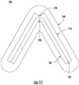
- FIG. 11 is a cross-sectional view of a folded expandable breast implant 100.
- the expandable breast implant 100 may fold at the location of the upper and lower grooves 220, 720 in the upper matrix 110 and lower matrix 130, respectively.
- FIG. 11 depicts one upper groove 220 in the upper matrix 110 and one lower groove 720 in the lower matrix 130.
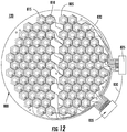
- FIG. 12 is a plan view of an example middle layer 120.
- the middle layer 120 comprises a flexible circuit "board.”
- the flexible circuit board is a printed circuit on thin, flexible film 800 (hereinafter “flex printed circuit” or "FPC") as depicted in FIG. 12 .
- the FPC 800 is polyurethane.
- the FPC 800 comprises a plurality of cells 805. Each cell 805 may be hexagonally shaped.
- the configuration of the cells 805 in the FPC 800 should generally align with the cells 105 in the upper matrix 110 and the wells 135 in the lower matrix 130. Accordingly, the shape of the cells 805 is illustrative, and the cells 805 may be constructed in any geometric shape that is complimentary to the cells 105 and the wells 135.
- the cells 805 may be arranged in a honeycomb structure as shown in FIG. 12 .
- Each cell 805 comprises a resistor 815, conductors 820, and an area of thin film 810.
- FIG. 12 depicts a circular resistor 815.
- the conductors 820 terminate at a first end at the resistor 815, and at a second end at a power bus 825.
- the power bus 825 is electrically coupled via a conductor 830 to the control system 835.
- circuit may be printed on the polyurethane sheet as shown, the circuit may be coupled to the polyurethane sheet by glue heat or another appropriate manner.
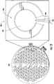
- FIG. 13 shows a top view of a FPC 800 and a magnified view of a single cell 805 in the FPC 800.
- the magnified view of a cell 805 shows a resistor 815, conductors 820, and an area of thin film 810 substantially surrounded by the circular resistor 815.
- the cell 805 may also include a sensor 840.
- the sensor 840 which is coupled to the control system 835 by one or more conductors (not shown) may comprise a pressure sensor or chemical sensor, and detects whether the reagents have mixed and reacted successfully.
- the sensor 840 may comprise any sensor that one skilled in the art would understand would detect successful completion of the reaction.
- the sensor 840 is shown in Figure 13 as integral to each cell 805, one or more sensors 840 may be utilized for the entire implant.
- each resistor 815 may have a resistivity of approximately 123 ohms and heat to a temperature of approximately 120°C. Because the melting temperature of the FPC 800 is lower than 120°C, the area of thin film 810 will melt and rupture as each resistor 815 achieves a temperature of approximately 120°C.
- FIG. 12 and 13 are shown to have a circular design. However, the design of the resistors 815 may be in any shape.
- FIG. 14A, 14B, and 14C are diagrams of top views of example resistors 815.
- FIG. 14A, 14B, and 14C illustrate alternative designs of the resistors 815.
- FIG. 15 is a block diagram of a control system 835 in which one or more features of the disclosure may be implemented.
- the control system 835 includes a power source 1500, one or more input devices 1505, a memory 1510, one or more output devices 1515, and a processor 1520. It should be understood that the control system 835 may include additional components not shown in FIG. 15 .
- the power source 1500 supplies power to the control system 835.
- the power source 1500 may include, but is not limited to, a battery or an inductive power receiver, which receives power through an inductive power generator (not shown) external to the implant 100.
- the input devices 1505 may include an antenna or other wireless network connection (e.g., any wireless interface for transmission and/or reception of wireless signals).
- the processor 1520 receives and transmits information via radio frequency (RF) communication such as Bluetooth, near field communication (NFC), or Wi-Fi.
- RF radio frequency
- the input devices 1505 may include signals from sensors 840 in the cells 805 to indicate whether a chemical process, explained in FIG. 16 hereinafter, has been successfully completed.
- the memory 1510 may include a volatile or non-volatile memory, for example, random access memory (RAM), dynamic RAM, or a cache.
- RAM random access memory
- dynamic RAM dynamic RAM
- cache a cache
- the memory 1510 stores information which may include the unique address of each cell 805.
- the output devices 1515 include one or more current drivers that are coupled to the conductors 820 of selected cells 805. These current drivers may apply current to the appropriate conductors 820 to activate a desired resistor 815.
- the processor 1520 is configured to receive a signal via an input device 1505.
- the processor 1520 determines the appropriate action to take, which may include selection of one more resistors 815 and ultimately energizing those resistors. As such, the processor 1520 selectively activates the appropriate resistor 815 of the desired cell 805.
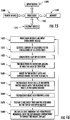
- FIG. 16 is a flow diagram of a process for expanding the breast implant 100.
- the process is initiated (step 1600) when the processor 1520 wirelessly receives an input from an input device 1505.
- the input comprises an instruction to activate one or more cells 805.
- the processor 1520 "translates" the instruction into one or more addresses of one or more cells 805.
- the output device 1515 drives current to the selected cell 805. Therefore, current is delivered to conductors 820 of the selected cell 805 (step 1610).
- the conductors 820 energize one or more resistors 815 (step 1620). As the selected resistor 815 heats up, the area of thin film 810 substantially surrounded by the heated resistor 815 melts (step 1630).
- step 1640 holes are introduced in the middle layer 120 (step 1640) allowing the first reagent 235 in the cells 105 from the upper matrix 110 to mix with the second reagent 635 in the wells 135 of the lower matrix 130 (step 1650).
- the mixed reagents 235, 635 react and release a gas (step 1660).
- the gas produced by the reaction is released through the openings in the top of the upper matrix 110 (step 1670).
- the released gas may permeate through the hydrophobic membrane 150 into the expandable shell 160 to expand the implant 100 (step 1680).
- the implant 100 may be filled with silicone, whereby the gas permeates throughout the silicone and inflates the expandable shell 160.
- the implant 100 is empty and only fills the expandable shell 160.
- the implant 100 may include a plurality of separate compartments, and the gas inflates the plurality of separate compartments.
- the expandable breast implant 100 may be configured to limit the number of repetitions per hour and/or per day to avoid overexpansion of the expandable breast implant 100.
- the processor 1520 may provide a limit on the number of resistors 815 that are activated within a certain amount of time. Additionally, the processor 1520 may be pre-programmed to activate the resistors 815 in a certain sequence, which may be automatically implemented with any intervention by the physician or the patient.
- the processor 1520 may wirelessly communicate the measurements taken by the one or more sensors 840 to a network (not shown), for ultimate reception by a physician.
- a physician may remotely monitor the course of treatment (i.e. expansion) if the expansion process is self-administered or administered automatically via a pre-programmed sequence.
- the sensor 840 comprises a pressure sensor, once the total pressure of the expandable implant reaches a predetermined level, power to the resistors 815 is removed, and alternatively permanently disconnected.
- At least one advantage of this expandable breast implant 100 is that the patient may expand the size of the implant 100 without additional surgeries or invasive procedures. In addition, it is possible to avoid the issues that arise at high elevations as experienced in breast implants that contain pressurized carbon dioxide cartridges.
Landscapes
- Health & Medical Sciences (AREA)
- General Health & Medical Sciences (AREA)
- Public Health (AREA)
- Engineering & Computer Science (AREA)
- Veterinary Medicine (AREA)
- Oral & Maxillofacial Surgery (AREA)
- Transplantation (AREA)
- Life Sciences & Earth Sciences (AREA)
- Animal Behavior & Ethology (AREA)
- Biomedical Technology (AREA)
- Chemical & Material Sciences (AREA)
- Epidemiology (AREA)
- Heart & Thoracic Surgery (AREA)
- Vascular Medicine (AREA)
- Cardiology (AREA)
- Dermatology (AREA)
- Medicinal Chemistry (AREA)
- Business, Economics & Management (AREA)
- General Business, Economics & Management (AREA)
- Medical Informatics (AREA)
- Primary Health Care (AREA)
- Inorganic Chemistry (AREA)
- Chemical Kinetics & Catalysis (AREA)
- Prostheses (AREA)
Abstract
Description
- Current breast implant procedures involve a complicated series of major and minor medical procedures, which are a source of pain and inconvenience for the patient. In the first major medical procedure, a physician makes an incision in the patient and inserts a tissue expander to create space between the skin and the muscle. Thereafter, a series of minor medical procedures are required to expand the tissue expander to the desired size. This procedure is done through multiple saline injections performed by a physician every few weeks. In addition to the inconvenience of multiple physician visits, the saline injections involve a long, painful, and uncomfortable process for the patient. After the tissue expander has been expanded to the desired size, a second major medical procedure is performed to remove the expander and insert a permanent breast implant into the space created by the tissue expander.
- There have been developments in expandable breast implants to reduce the number of procedures and physician visits. For example, some devices used pressurized carbon dioxide cartridges, which were susceptible to failure at high elevations. With such implants, a patient could not travel by air for an extended period of time. Accordingly, these implants were not an optimal solution.
- It would therefore be desirable to have an expandable breast implant that eliminates the need for multiple medical procedures and injections. It would also be desirable to have an expandable breast implant capable of self-administered expansion that is safe and convenient.
- There is provided, according to the described embodiments, a medical apparatus including an expandable breast implant that eliminates the need for multiple procedures and injections, with the capability for self-administered expansion that is safe in any environment. The expandable breast implant includes an upper matrix, a lower matrix, and a middle layer that separates the upper matrix and lower matrix. The upper matrix is covered by a hydrophobic membrane.
The upper matrix comprises a plurality of cells containing a first reagent. The lower matrix comprises a plurality of wells containing a second reagent. The middle layer acts as a barrier between the upper matrix and the lower matrix. The middle layer may be activated and controlled to form openings at selected locations. The first reagent from the cells in the upper matrix mixes with the second reagent from the wells in the lower matrix through the selected openings in the middle layer. The reagents react to generate a gas, which is released through the hydrophobic membrane top of the upper matrix. The gas permeates the hydrophobic membrane into an expandable shell to enlarge the breast implant. - The present embodiments are illustrated by way of example, and not by way of limitation, in the figures of the accompanying drawings in which:
-
FIG. 1 is an example cross-sectional view of a multi-layer design for an expandable breast implant; -
FIG. 2 is a top view of an example upper matrix; -
FIG. 3 is an isometric view of the top of the upper matrix; -
FIG. 4 is a bottom view of the upper matrix; -
FIG. 5 is a bottom view of the upper matrix in an alternative embodiment; -
FIG. 6 is an isometric view showing the bottom of the upper matrix in the alternative embodiment; -
FIG. 7 is a top view of an example lower matrix; -
FIG. 8 is a top view of the lower matrix in an alternative embodiment; -
FIG. 9 is a bottom view of the lower matrix; -
FIG. 10 is an isometric view of the multi-layer structure comprising the upper matrix, lower matrix, and middle layer; -
FIG. 11 is an example cross-sectional view of a folded expandable breast implant; -
FIG. 12 is a plan view of an example middle layer comprising a flex printed circuit ("FPC"); -
FIG. 13 is a top view of a FPC showing a magnified view of a cell in the FPC; -
FIG. 14A is a top view of a resistor; -
FIG. 14B is a top view of a resistor in an alternative embodiment; -
FIG. 14C is a top view of a resistor in another alternative embodiment; -
FIG. 15 is a block diagram of a control system that is electrically coupled to the FPC; and -
FIG. 16 is a flow diagram of a procedure which is used in conjunction with the disclosed embodiments. - Various embodiments are described in the following paragraphs. Where like elements have been depicted in multiple embodiments, identical or similar reference numerals have been used for ease of understanding.
-
FIG. 1 is an example cross-sectional view of a multi-layerexpandable breast implant 100. Theexpandable breast implant 100 includes anexpandable shell 160, anupper matrix 110, alower matrix 130, and amiddle layer 120. In one embodiment, theexpandable shell 160 may comprise silicone, and theshell 160 is filled with one or more different types of silicone. In other embodiments, the shell may be filled with saline or another material, or even unfilled. - The
upper matrix 110 comprises a plurality ofcells 105. As shown inFIG. 1 , thecells 105 may be angularly shaped with thecell 105 gradually increasing in size toward themiddle layer 120. Eachcell 105 contains a first reagent. Thelower matrix 130 comprises a plurality ofwells 135. Eachwell 135 is aligned with acomplimentary cell 105. Thewells 135 contain a second reagent. Themiddle layer 120 forms a barrier between theupper matrix 110 andlower matrix 130. Theupper matrix 110,lower matrix 130, andmiddle layer 120 may be coupled together with glue, heat-sealing, or any other appropriate manner to form themulti-layer structure 140. Themulti-layer structure 140 may be encased in ahydrophobic membrane 150, such that gases permeate thehydrophobic membrane 150 while liquid is denied passage. In one alternative embodiment, thehydrophobic membrane 150 covers only the top of theupper matrix 110. In this embodiment thehydrophobic membrane 150 may be coupled to the top of theupper matrix 110 via any appropriate manner such as glue, heat-sealing, or the like. Themulti-layer structure 140 and thehydrophobic membrane 150 are further encased in anexpandable shell 160 to form theexpandable breast implant 100. In an alternative embodiment, thehydrophobic membrane 150 may cover thelower matrix 130, or both theupper matrix 110 and thelower matrix 130. In the event that thehydrophobic membrane 150 covers thelower matrix 130, complimentary holes would be located in thewells 135 of thelower matrix 130. -
FIG. 2 is a top view of theupper matrix 110. Theupper matrix 110 may comprise polyurethane, rubber or silicone.FIG. 2 depicts a top view of the plurality ofcells 105 in theupper matrix 110, which comprise openings in thetop side 210 of theupper matrix 110. Although thecells 105 are shown as hexagonal in shape, the shape of the top of thecells 105 is illustrative, and those skilled in the art would understand that thecells 105 may be configured in any geometric shape that would properly accommodate the first reagent. Thehydrophobic membrane 150 covers the entiretop side 210 of theupper matrix 110. However,FIG. 2 does not show a portion of thehydrophobic membrane 150, for explanatory purposes. Thehydrophobic membrane 150 is flexible and permits the gas that is generated to permeate through thehydrophobic membrane 150. Thetop side 210 of theupper matrix 110 may include at least oneupper groove 220 to increase the pliability of theupper matrix 110.FIG. 2 depicts oneupper groove 220 spanning the diameter of theupper matrix 110, although more than one grove may be utilized. -
FIG. 3 shows a perspective view of thetop side 210 of theupper matrix 110 illustrating the tops of thecells 105 and theupper groove 220. In this figure, as withFIG. 2 , a portion of thehydrophobic membrane 150 is not shown for simplicity. -
FIG. 4 shows thebottom side 205 of theupper matrix 110. Thebottom side 205 is configured to be in contact with themiddle layer 120. Thecells 105 are shown as hexagonal in shape. However, as aforementioned, the shape of thecells 105 is illustrative and may be in any appropriate geometric shape. As illustrated inFIG. 4 , thecells 105 may be arranged in a honeycomb pattern. Thebottom side 205 of theupper matrix 110 may include a number ofholes 230 configured to receive pegs from thelower matrix 130, in order to keep theupper matrix 110 and thelower matrix 130 properly aligned. - The
cells 105 contain afirst reagent 235. In one embodiment, thefirst reagent 235 by way of example is sodium bicarbonate. Thefirst reagent 235 may fill afew cells 105 or a portion of thecells 105. However, it is most likely that most or all of thecells 105 contain thefirst reagent 235. In this embodiment, each cell may contain approximately 0.06g of sodium bicarbonate. However, more or less reagent, or a different reagent, may be utilized. -
FIG. 5 is an alternative embodiment of theupper matrix 110 whereby a plurality ofcells 105 may be grouped together to form a larger cell, or a cell "cluster". As shown inFIG. 5 , and also in the perspective view ofFIG. 6 , for example, cluster A is a 5 cell grouping and cluster B is a 4 cell grouping. Any size cell or grouping may be configured, depending upon the amount of gas desired to be generated at one time. Thecells 105 may be the shape of an inverted funnel. The inverted funnel shape of thecells 105 optimizes the mixing of the first reagent and the second reagent. The purpose and process of the mixing of the reagents will be described in greater detail hereinafter. -
FIG. 7 shows a top view of thelower matrix 130. Thelower matrix 130 may comprise polyurethane, rubber or silicone. Thetop side 610 of thelower matrix 130 is configured to be in contact with themiddle layer 120. Thelower matrix 130 may include a number ofpegs 630 that are complimentary to, and insert into, theholes 230 of theupper matrix 110. Thehole 230 and peg 630 configuration is an optional means of coupling theupper matrix 110,lower matrix 130, andmiddle layer 120 together and also the membrane. The arrangement of thewells 135 in thelower matrix 130 should optimally match the configuration of thecells 105 in theupper matrix 110. The perimeter of each well 135 preferably aligns with the perimeter of acell 105 in theupper matrix 110, although exact alignment is not required. As an example,FIG. 7 showssingle wells 135 that align with thesingle cells 105 depicted inFIG. 4 . Typically, allwells 135 contain thesecond reagent 635, which may be at least 70% acetic acid depending upon the volume of the wells. However, more or less reagent, or a different reagent, may be utilized. Although thesecond reagent 635 is graphically illustrated as filling only afew wells 135, it is most likely that most or all of thewells 135 contain thesecond reagent 635. - As explained in a process described hereinafter, when one or more openings in the
middle layer 120 are formed, thefirst reagent 235 in thecells 105 passes through openings in themiddle layer 120 and mixes with thesecond reagent 635 in thewells 135. Thereagents - In one embodiment, the
first reagent 235 is sodium biocarbonate and thesecond reagent 635 is acetic acid, wherein the reaction produces carbon dioxide. Eachcell 105 and well 135 may contain enough materials to produce 15 cc of carbon dioxide. -
FIG. 8 is a top view of thelower matrix 130 in an alternative embodiment. This embodiment includes one or more groupings ofwells 135, comprising a plurality ofwells 135 joined together to form a well "cluster." Alternatively, thesewells 135 may simply comprise a larger-sized well 135. As with the embodiment shown inFIG. 7 , each well 135 cluster is configured to be generally aligned with acomplimentary cell 105 in theupper matrix 110. Accordingly, the embodiment of thelower matrix 130 shown inFIG. 8 would be complimentary with the embodiment of theupper matrix 110 shown inFIG. 5 . As such, the perimeter of each well 135 may be configured to overlap the same area as a cluster ofcells 105 in theupper matrix 110. Well A is an example of a well 135 configured to accommodate a 5cell 105 cluster, and Well B is an example of a well 135 configured to accommodate a 4cell 105 cluster. -
FIG. 9 is a bottom view of thelower matrix 130. Thebottom side 710 comprises a surface which encloses thewells 135 and contains thesecond reagent 635 within thewells 135. Thebottom side 710 may comprise at least onelower groove 720 that spans the diameter of thelower matrix 130 to increase the pliability of thelower matrix 130, and is complimentary to theupper grove 220. -
FIG. 10 is an isometric view of themulti-layer structure 140 comprising thehydrophobic membrane 150, theupper matrix 110, thelower matrix 130, and themiddle layer 120. As shown inFIG. 10 , theupper matrix 110 includes at least oneupper groove 220, and thelower matrix 130 includes at least one complimentary matchinglower groove 720. The at least oneupper groove 220 in theupper matrix 110 and the at least onelower groove 720 in thelower matrix 130 increase the pliability of themulti-layer structure 140 and allows themulti-layer structure 140 to fold. Advantageously, thesegrooves upper groove 220 on theupper matrix 110 and onelower groove 720 on thelower matrix 130 are shown, it should be understood that theupper matrix 110 andlower matrix 130 may have multiple grooves to allow theexpandable breast implant 100 to fold at multiple locations. -
FIG. 11 is a cross-sectional view of a foldedexpandable breast implant 100. Theexpandable breast implant 100 may fold at the location of the upper andlower grooves upper matrix 110 andlower matrix 130, respectively.FIG. 11 depicts oneupper groove 220 in theupper matrix 110 and onelower groove 720 in thelower matrix 130. -
FIG. 12 is a plan view of an examplemiddle layer 120. Themiddle layer 120 comprises a flexible circuit "board." In one embodiment, the flexible circuit board is a printed circuit on thin, flexible film 800 (hereinafter "flex printed circuit" or "FPC") as depicted inFIG. 12 . In one embodiment, theFPC 800 is polyurethane. TheFPC 800 comprises a plurality ofcells 805. Eachcell 805 may be hexagonally shaped. The configuration of thecells 805 in theFPC 800 should generally align with thecells 105 in theupper matrix 110 and thewells 135 in thelower matrix 130. Accordingly, the shape of thecells 805 is illustrative, and thecells 805 may be constructed in any geometric shape that is complimentary to thecells 105 and thewells 135. Thecells 805 may be arranged in a honeycomb structure as shown inFIG. 12 . Eachcell 805 comprises aresistor 815,conductors 820, and an area ofthin film 810.FIG. 12 depicts acircular resistor 815. Theconductors 820 terminate at a first end at theresistor 815, and at a second end at apower bus 825. Thepower bus 825 is electrically coupled via aconductor 830 to thecontrol system 835. - Although the circuit may be printed on the polyurethane sheet as shown, the circuit may be coupled to the polyurethane sheet by glue heat or another appropriate manner.
-
FIG. 13 shows a top view of aFPC 800 and a magnified view of asingle cell 805 in theFPC 800. The magnified view of acell 805 shows aresistor 815,conductors 820, and an area ofthin film 810 substantially surrounded by thecircular resistor 815. - In an alternative embodiment, the
cell 805 may also include asensor 840. Thesensor 840, which is coupled to thecontrol system 835 by one or more conductors (not shown) may comprise a pressure sensor or chemical sensor, and detects whether the reagents have mixed and reacted successfully. Alternatively, thesensor 840 may comprise any sensor that one skilled in the art would understand would detect successful completion of the reaction. Although thesensor 840 is shown inFigure 13 as integral to eachcell 805, one ormore sensors 840 may be utilized for the entire implant. - As will be explained in greater detail hereinafter, as current is applied to the
conductors 820, it flows through theresistor 815, thereby energizing and heating theresistor 815. In one embodiment, theresistor 815 receives 1 W of electric power. When theresistor 815 achieves the melting temperature of theFPC 800, theFPC 800 melts and ruptures, thereby allowing the first andsecond reagents resistor 815 may have a resistivity of approximately 123 ohms and heat to a temperature of approximately 120°C. Because the melting temperature of theFPC 800 is lower than 120°C, the area ofthin film 810 will melt and rupture as eachresistor 815 achieves a temperature of approximately 120°C. - The
resistors 815 inFIG. 12 and13 are shown to have a circular design. However, the design of theresistors 815 may be in any shape.FIG. 14A, 14B, and 14C are diagrams of top views ofexample resistors 815.FIG. 14A, 14B, and 14C illustrate alternative designs of theresistors 815. -
FIG. 15 is a block diagram of acontrol system 835 in which one or more features of the disclosure may be implemented. Thecontrol system 835 includes apower source 1500, one ormore input devices 1505, amemory 1510, one ormore output devices 1515, and aprocessor 1520. It should be understood that thecontrol system 835 may include additional components not shown inFIG. 15 . - The
power source 1500 supplies power to thecontrol system 835. Thepower source 1500 may include, but is not limited to, a battery or an inductive power receiver, which receives power through an inductive power generator (not shown) external to theimplant 100. - The
input devices 1505 may include an antenna or other wireless network connection (e.g., any wireless interface for transmission and/or reception of wireless signals). In one embodiment, theprocessor 1520 receives and transmits information via radio frequency (RF) communication such as Bluetooth, near field communication (NFC), or Wi-Fi. In one embodiment, theinput devices 1505 may include signals fromsensors 840 in thecells 805 to indicate whether a chemical process, explained inFIG. 16 hereinafter, has been successfully completed. - The
memory 1510 may include a volatile or non-volatile memory, for example, random access memory (RAM), dynamic RAM, or a cache. Thememory 1510 stores information which may include the unique address of eachcell 805. - The
output devices 1515 include one or more current drivers that are coupled to theconductors 820 of selectedcells 805. These current drivers may apply current to theappropriate conductors 820 to activate a desiredresistor 815. - The
processor 1520 is configured to receive a signal via aninput device 1505. Theprocessor 1520 determines the appropriate action to take, which may include selection of onemore resistors 815 and ultimately energizing those resistors. As such, theprocessor 1520 selectively activates theappropriate resistor 815 of the desiredcell 805. -
FIG. 16 is a flow diagram of a process for expanding thebreast implant 100. The process is initiated (step 1600) when theprocessor 1520 wirelessly receives an input from aninput device 1505. Typically, the input comprises an instruction to activate one ormore cells 805. If necessary, theprocessor 1520 "translates" the instruction into one or more addresses of one ormore cells 805. Once theprocessor 1520 determines whichcell 805 to activate, theoutput device 1515 drives current to the selectedcell 805. Therefore, current is delivered toconductors 820 of the selected cell 805 (step 1610). Theconductors 820 energize one or more resistors 815 (step 1620). As the selectedresistor 815 heats up, the area ofthin film 810 substantially surrounded by theheated resistor 815 melts (step 1630). As the area ofthin film 810 melts, holes are introduced in the middle layer 120 (step 1640) allowing thefirst reagent 235 in thecells 105 from theupper matrix 110 to mix with thesecond reagent 635 in thewells 135 of the lower matrix 130 (step 1650). Themixed reagents hydrophobic membrane 150 into theexpandable shell 160 to expand the implant 100 (step 1680). - It should be understood that there may be different configurations of the implant once the gas is generated. In a first embodiment, the
implant 100 may be filled with silicone, whereby the gas permeates throughout the silicone and inflates theexpandable shell 160. In a second embodiment, theimplant 100 is empty and only fills theexpandable shell 160. In yet another embodiment, theimplant 100 may include a plurality of separate compartments, and the gas inflates the plurality of separate compartments. Those of skill in that art would understand that other embodiments would be possible in accordance with the teachings herein. - This process may be repeated in accordance with a physician's care plan to expand the
implant 100 to the desired size. Theexpandable breast implant 100 may be configured to limit the number of repetitions per hour and/or per day to avoid overexpansion of theexpandable breast implant 100. In this manner, theprocessor 1520 may provide a limit on the number ofresistors 815 that are activated within a certain amount of time. Additionally, theprocessor 1520 may be pre-programmed to activate theresistors 815 in a certain sequence, which may be automatically implemented with any intervention by the physician or the patient. - In yet another embodiment, the
processor 1520 may wirelessly communicate the measurements taken by the one ormore sensors 840 to a network (not shown), for ultimate reception by a physician. In this matter, a physician may remotely monitor the course of treatment (i.e. expansion) if the expansion process is self-administered or administered automatically via a pre-programmed sequence. As one optional safety precaution, if thesensor 840 comprises a pressure sensor, once the total pressure of the expandable implant reaches a predetermined level, power to theresistors 815 is removed, and alternatively permanently disconnected. - At least one advantage of this
expandable breast implant 100 is that the patient may expand the size of theimplant 100 without additional surgeries or invasive procedures. In addition, it is possible to avoid the issues that arise at high elevations as experienced in breast implants that contain pressurized carbon dioxide cartridges.
Claims (20)
- An expandable implant comprising:a flexible shell, enclosing:an upper matrix having a plurality of cells, each cell including a first reagent;a lower matrix having a plurality of wells, each well being at least partially aligned with one of said cells, and each well including a second reagent; anda middle layer between the upper matrix and the lower matrix, having at least one selectively activateable membrane, each said at least one membrane being located between a cell and its aligned well;a controller, for activating at least one of said at least one membranes, and permitting the first reagent to mix with said second reagent to produce a gas, and expand said flexible shell.
- The expandable implant of claim 1, further comprising hydrophobic membrane.
- The expandable implant of claim 2, wherein each of the plurality of cells are arranged in a honeycomb structure.
- The expandable implant of claim 2, wherein each of said at least one membrane includes a resistor, and current that is applied to the resistor activates the said at least one membrane .
- The expandable implant of claim 2, wherein a plurality of cells comprise a cell cluster.
- The expandable implant of claim 4 further comprising a controller, which selectively applies current to the resistors.
- The expandable implant of claim 2, wherein each of the plurality of cells contains sodium bicarbonate.
- The expandable implant of claim 1, further comprising at least one sensor, for determining whether said gas has been produced.
- The expandable implant of claim 1, wherein the middle layer comprises a flex printed circuit.
- The expandable implant of claim 9, wherein the flex printed circuit includes a plurality of resistors.
- The expandable implant of claim 10, wherein each of the plurality of resistors are selectively activatable.
- The expandable implant of claim 1, wherein the middle layer comprises a layer of polyurethane coupled to a flex printed circuit.
- The expandable implant of claim 1, wherein each of the plurality of wells include ascetic acid.
- The expandable implant of claim 1, wherein the controller automatically activates a plurality of said membranes in a predetermined sequence.
- A method for expanding a breast implant comprising:providing a flexible shell, enclosing:an upper matrix having a plurality of cells, each cell including a first reagent;a lower matrix having a plurality of wells, each well-being at least partially aligned with one of said cells, and each well including a second reagent; anda middle layer between the upper matrix and the lower matrix, having a plurality of selectively activatable membranes, each membrane being located between a cell and its aligned well;activating one of said membranes, and permitting the first reagent to mix with said second reagent to produce a gas, to expand said flexible shell.
- The method for expanding a breast implant of claim 15, wherein the controller is programmed to automatically activate a plurality of said membranes
- The method for expanding a breast implant of claim 16, wherein the automatic activation comprises a predetermined sequence on a predetermined schedule.
- The method for expanding a breast implant of claim 17, further comprising utilizing at least one sensor to confirm whether said gas has been produced.
- The method for expanding a breast implant of claim 18, further comprising wirelessly transmitting sensor data to a physician.
- The method for expanding a breast implant of claim 16, further comprising the controller wirelessly programmed by a physician.
Applications Claiming Priority (1)
| Application Number | Priority Date | Filing Date | Title |
|---|---|---|---|
| US15/983,035 US10660742B2 (en) | 2018-05-17 | 2018-05-17 | Expandable breast implant |
Publications (1)
| Publication Number | Publication Date |
|---|---|
| EP3569193A1 true EP3569193A1 (en) | 2019-11-20 |
Family
ID=66589336
Family Applications (1)
| Application Number | Title | Priority Date | Filing Date |
|---|---|---|---|
| EP19174906.8A Withdrawn EP3569193A1 (en) | 2018-05-17 | 2019-05-16 | Expandable breast implant |
Country Status (6)
| Country | Link |
|---|---|
| US (1) | US10660742B2 (en) |
| EP (1) | EP3569193A1 (en) |
| CN (1) | CN110495971A (en) |
| AU (1) | AU2019203428A1 (en) |
| BR (1) | BR102019009932A2 (en) |
| CO (1) | CO2019005091A1 (en) |
Families Citing this family (5)
| Publication number | Priority date | Publication date | Assignee | Title |
|---|---|---|---|---|
| US9855132B2 (en) * | 2015-01-30 | 2018-01-02 | Arthrex, Inc. | Ligament fixation device and method |
| CA3013698A1 (en) | 2016-02-09 | 2017-08-17 | Establishment Labs S.A. | Transponders and sensors for implantable medical devices and methods of use thereof |
| KR102479359B1 (en) | 2016-10-28 | 2022-12-19 | 이스타블리쉬먼트 렙스 에스.에이. | Tissue expander, manufacturing method thereof and method of casting |
| WO2018195476A1 (en) * | 2017-04-20 | 2018-10-25 | The Regents Of The University Of California | Systems and methods for acellular dermal matrix fenestrations in prepectoral breast reconstruction |
| GB201805484D0 (en) * | 2018-04-04 | 2018-05-16 | Gc Aesthetics Mfg Ltd | Implant |
Citations (2)
| Publication number | Priority date | Publication date | Assignee | Title |
|---|---|---|---|---|
| US20100010531A1 (en) * | 2004-09-21 | 2010-01-14 | Tadmor Shalon | Tissue Expansion Devices |
| EP2958492A1 (en) * | 2013-02-21 | 2015-12-30 | Airxpanders, Inc. | Tissue expanders, implants, and methods of use |
Family Cites Families (14)
| Publication number | Priority date | Publication date | Assignee | Title |
|---|---|---|---|---|
| US6228116B1 (en) * | 1987-12-22 | 2001-05-08 | Walter J. Ledergerber | Tissue expander |
| US5571178A (en) * | 1991-02-22 | 1996-11-05 | Ledergerber; Walter J. | Breast implant introducer |
| KR200203718Y1 (en) * | 2000-03-20 | 2000-11-15 | 안정오 | A portable heater |
| US7785291B2 (en) * | 2005-03-01 | 2010-08-31 | Tulip Medical Ltd. | Bioerodible self-deployable intragastric implants |
| WO2006108420A1 (en) * | 2005-04-12 | 2006-10-19 | Millimed A/S | Inflatable medical device comprising a permeable membrane |
| AU2010272575B2 (en) * | 2009-07-17 | 2015-07-30 | Implantica Patent Ltd. | Breast implant system |
| IL202160A0 (en) * | 2009-11-16 | 2010-06-16 | Rolan Knowledge And Services L | Female breasts implants |
| JP2013518674A (en) * | 2010-02-05 | 2013-05-23 | アラーガン、インコーポレイテッド | Inflatable prosthesis and method of making the same |
| US10123868B2 (en) * | 2011-10-19 | 2018-11-13 | Hilton Becker | Hybrid breast implant, method for making and using same |
| CN105142572B (en) * | 2013-01-30 | 2018-05-11 | 因普利特有限公司 | human implantable tissue expander |
| US10932946B2 (en) * | 2015-07-31 | 2021-03-02 | Agency For Science, Technology And Research | Device for insertion into a body cavity, and method of fabrication thereof |
| DE202015007895U1 (en) * | 2015-11-13 | 2017-02-15 | Amoena Medizin-Orthopädie-Technik GmbH | breast prosthesis |
| KR102479359B1 (en) * | 2016-10-28 | 2022-12-19 | 이스타블리쉬먼트 렙스 에스.에이. | Tissue expander, manufacturing method thereof and method of casting |
| US10729508B2 (en) * | 2017-03-07 | 2020-08-04 | Medtronic Advanced Energy Llc | Multi-chambered breast tissue expander |
-
2018
- 2018-05-17 US US15/983,035 patent/US10660742B2/en not_active Expired - Fee Related
-
2019
- 2019-05-15 AU AU2019203428A patent/AU2019203428A1/en not_active Abandoned
- 2019-05-15 BR BR102019009932A patent/BR102019009932A2/en not_active Application Discontinuation
- 2019-05-16 EP EP19174906.8A patent/EP3569193A1/en not_active Withdrawn
- 2019-05-17 CO CONC2019/0005091A patent/CO2019005091A1/en unknown
- 2019-05-17 CN CN201910410844.6A patent/CN110495971A/en active Pending
Patent Citations (2)
| Publication number | Priority date | Publication date | Assignee | Title |
|---|---|---|---|---|
| US20100010531A1 (en) * | 2004-09-21 | 2010-01-14 | Tadmor Shalon | Tissue Expansion Devices |
| EP2958492A1 (en) * | 2013-02-21 | 2015-12-30 | Airxpanders, Inc. | Tissue expanders, implants, and methods of use |
Also Published As
| Publication number | Publication date |
|---|---|
| CN110495971A (en) | 2019-11-26 |
| CO2019005091A1 (en) | 2020-11-20 |
| AU2019203428A1 (en) | 2019-12-05 |
| BR102019009932A2 (en) | 2019-12-10 |
| US10660742B2 (en) | 2020-05-26 |
| US20190350697A1 (en) | 2019-11-21 |
Similar Documents
| Publication | Publication Date | Title |
|---|---|---|
| US10660742B2 (en) | Expandable breast implant | |
| US11026825B2 (en) | Methods, devices, and systems for obesity treatment | |
| US9445930B2 (en) | Methods, devices, and systems for obesity treatment | |
| US6985088B2 (en) | Telemetry module with configurable data layer for use with an implantable medical device | |
| US8326439B2 (en) | Treatment devices with delivery-activated inflatable members, and associated systems and methods for treating the spinal cord and other tissues | |
| US8019441B2 (en) | Collapsible/expandable tubular electrode leads | |
| JP4354521B2 (en) | Flexible microchip device for ocular and other applications | |
| CN104602719B (en) | Wound connection gasket with RFID and integrated strain gauge pressure sensor | |
| JP5765717B2 (en) | Intragastric balloon system and treatment processes and products | |
| US7797054B2 (en) | Expandable systems for medical electrical stimulation | |
| JP4464282B2 (en) | Curable medium for implantable medical devices | |
| US20040267234A1 (en) | Implantable ultrasound systems and methods for enhancing localized delivery of therapeutic substances | |
| CN103179929A (en) | Interactive, wireless reduced-pressure dressings, methods, and systems | |
| JP2009538218A (en) | Improved method and apparatus for suppressing appetite and / or reducing food intake | |
| WO2005002474A1 (en) | Disk therapy implant, and operation method of implant | |
| WO2021005382A1 (en) | Medical device | |
| KR20160062060A (en) | Secured spinal cord stimulator leads and catheters | |
| KR20200031457A (en) | Implantable storage device | |
| JPH01285274A (en) | Chemical agent gradual release apparatus |
Legal Events
| Date | Code | Title | Description |
|---|---|---|---|
| PUAI | Public reference made under article 153(3) epc to a published international application that has entered the european phase |
Free format text: ORIGINAL CODE: 0009012 |
|
| STAA | Information on the status of an ep patent application or granted ep patent |
Free format text: STATUS: THE APPLICATION HAS BEEN PUBLISHED |
|
| AK | Designated contracting states |
Kind code of ref document: A1 Designated state(s): AL AT BE BG CH CY CZ DE DK EE ES FI FR GB GR HR HU IE IS IT LI LT LU LV MC MK MT NL NO PL PT RO RS SE SI SK SM TR |
|
| AX | Request for extension of the european patent |
Extension state: BA ME |
|
| STAA | Information on the status of an ep patent application or granted ep patent |
Free format text: STATUS: REQUEST FOR EXAMINATION WAS MADE |
|
| 17P | Request for examination filed |
Effective date: 20200420 |
|
| RBV | Designated contracting states (corrected) |
Designated state(s): AL AT BE BG CH CY CZ DE DK EE ES FI FR GB GR HR HU IE IS IT LI LT LU LV MC MK MT NL NO PL PT RO RS SE SI SK SM TR |
|
| STAA | Information on the status of an ep patent application or granted ep patent |
Free format text: STATUS: EXAMINATION IS IN PROGRESS |
|
| 17Q | First examination report despatched |
Effective date: 20200922 |
|
| GRAP | Despatch of communication of intention to grant a patent |
Free format text: ORIGINAL CODE: EPIDOSNIGR1 |
|
| STAA | Information on the status of an ep patent application or granted ep patent |
Free format text: STATUS: GRANT OF PATENT IS INTENDED |
|
| INTG | Intention to grant announced |
Effective date: 20240304 |
|
| STAA | Information on the status of an ep patent application or granted ep patent |
Free format text: STATUS: THE APPLICATION IS DEEMED TO BE WITHDRAWN |
|
| 18D | Application deemed to be withdrawn |
Effective date: 20240705 |