EP3569136A1 - Probe with a grating arranged inside a drive cable and a method for alignment of optics in an endoscopic probe - Google Patents
Probe with a grating arranged inside a drive cable and a method for alignment of optics in an endoscopic probe Download PDFInfo
- Publication number
- EP3569136A1 EP3569136A1 EP19163628.1A EP19163628A EP3569136A1 EP 3569136 A1 EP3569136 A1 EP 3569136A1 EP 19163628 A EP19163628 A EP 19163628A EP 3569136 A1 EP3569136 A1 EP 3569136A1
- Authority
- EP
- European Patent Office
- Prior art keywords
- light
- probe
- component
- grating
- drive cable
- Prior art date
- Legal status (The legal status is an assumption and is not a legal conclusion. Google has not performed a legal analysis and makes no representation as to the accuracy of the status listed.)
- Withdrawn
Links
Images


Classifications
-
- A—HUMAN NECESSITIES
- A61—MEDICAL OR VETERINARY SCIENCE; HYGIENE
- A61B—DIAGNOSIS; SURGERY; IDENTIFICATION
- A61B1/00—Instruments for performing medical examinations of the interior of cavities or tubes of the body by visual or photographical inspection, e.g. endoscopes; Illuminating arrangements therefor
- A61B1/00064—Constructional details of the endoscope body
- A61B1/00071—Insertion part of the endoscope body
- A61B1/0008—Insertion part of the endoscope body characterised by distal tip features
- A61B1/00096—Optical elements
-
- A—HUMAN NECESSITIES
- A61—MEDICAL OR VETERINARY SCIENCE; HYGIENE
- A61B—DIAGNOSIS; SURGERY; IDENTIFICATION
- A61B1/00—Instruments for performing medical examinations of the interior of cavities or tubes of the body by visual or photographical inspection, e.g. endoscopes; Illuminating arrangements therefor
- A61B1/00002—Operational features of endoscopes
- A61B1/00004—Operational features of endoscopes characterised by electronic signal processing
- A61B1/00006—Operational features of endoscopes characterised by electronic signal processing of control signals
-
- A—HUMAN NECESSITIES
- A61—MEDICAL OR VETERINARY SCIENCE; HYGIENE
- A61B—DIAGNOSIS; SURGERY; IDENTIFICATION
- A61B1/00—Instruments for performing medical examinations of the interior of cavities or tubes of the body by visual or photographical inspection, e.g. endoscopes; Illuminating arrangements therefor
- A61B1/00002—Operational features of endoscopes
- A61B1/00004—Operational features of endoscopes characterised by electronic signal processing
- A61B1/00009—Operational features of endoscopes characterised by electronic signal processing of image signals during a use of endoscope
-
- A—HUMAN NECESSITIES
- A61—MEDICAL OR VETERINARY SCIENCE; HYGIENE
- A61B—DIAGNOSIS; SURGERY; IDENTIFICATION
- A61B1/00—Instruments for performing medical examinations of the interior of cavities or tubes of the body by visual or photographical inspection, e.g. endoscopes; Illuminating arrangements therefor
- A61B1/00002—Operational features of endoscopes
- A61B1/00057—Operational features of endoscopes provided with means for testing or calibration
-
- A—HUMAN NECESSITIES
- A61—MEDICAL OR VETERINARY SCIENCE; HYGIENE
- A61B—DIAGNOSIS; SURGERY; IDENTIFICATION
- A61B1/00—Instruments for performing medical examinations of the interior of cavities or tubes of the body by visual or photographical inspection, e.g. endoscopes; Illuminating arrangements therefor
- A61B1/00064—Constructional details of the endoscope body
- A61B1/0011—Manufacturing of endoscope parts
-
- A—HUMAN NECESSITIES
- A61—MEDICAL OR VETERINARY SCIENCE; HYGIENE
- A61B—DIAGNOSIS; SURGERY; IDENTIFICATION
- A61B1/00—Instruments for performing medical examinations of the interior of cavities or tubes of the body by visual or photographical inspection, e.g. endoscopes; Illuminating arrangements therefor
- A61B1/00112—Connection or coupling means
- A61B1/00117—Optical cables in or with an endoscope
-
- A—HUMAN NECESSITIES
- A61—MEDICAL OR VETERINARY SCIENCE; HYGIENE
- A61B—DIAGNOSIS; SURGERY; IDENTIFICATION
- A61B1/00—Instruments for performing medical examinations of the interior of cavities or tubes of the body by visual or photographical inspection, e.g. endoscopes; Illuminating arrangements therefor
- A61B1/00163—Optical arrangements
- A61B1/00172—Optical arrangements with means for scanning
-
- A—HUMAN NECESSITIES
- A61—MEDICAL OR VETERINARY SCIENCE; HYGIENE
- A61B—DIAGNOSIS; SURGERY; IDENTIFICATION
- A61B1/00—Instruments for performing medical examinations of the interior of cavities or tubes of the body by visual or photographical inspection, e.g. endoscopes; Illuminating arrangements therefor
- A61B1/06—Instruments for performing medical examinations of the interior of cavities or tubes of the body by visual or photographical inspection, e.g. endoscopes; Illuminating arrangements therefor with illuminating arrangements
- A61B1/063—Instruments for performing medical examinations of the interior of cavities or tubes of the body by visual or photographical inspection, e.g. endoscopes; Illuminating arrangements therefor with illuminating arrangements for monochromatic or narrow-band illumination
-
- A—HUMAN NECESSITIES
- A61—MEDICAL OR VETERINARY SCIENCE; HYGIENE
- A61B—DIAGNOSIS; SURGERY; IDENTIFICATION
- A61B1/00—Instruments for performing medical examinations of the interior of cavities or tubes of the body by visual or photographical inspection, e.g. endoscopes; Illuminating arrangements therefor
- A61B1/06—Instruments for performing medical examinations of the interior of cavities or tubes of the body by visual or photographical inspection, e.g. endoscopes; Illuminating arrangements therefor with illuminating arrangements
- A61B1/0646—Instruments for performing medical examinations of the interior of cavities or tubes of the body by visual or photographical inspection, e.g. endoscopes; Illuminating arrangements therefor with illuminating arrangements with illumination filters
-
- A—HUMAN NECESSITIES
- A61—MEDICAL OR VETERINARY SCIENCE; HYGIENE
- A61B—DIAGNOSIS; SURGERY; IDENTIFICATION
- A61B1/00—Instruments for performing medical examinations of the interior of cavities or tubes of the body by visual or photographical inspection, e.g. endoscopes; Illuminating arrangements therefor
- A61B1/06—Instruments for performing medical examinations of the interior of cavities or tubes of the body by visual or photographical inspection, e.g. endoscopes; Illuminating arrangements therefor with illuminating arrangements
- A61B1/0661—Endoscope light sources
- A61B1/0669—Endoscope light sources at proximal end of an endoscope
-
- A—HUMAN NECESSITIES
- A61—MEDICAL OR VETERINARY SCIENCE; HYGIENE
- A61B—DIAGNOSIS; SURGERY; IDENTIFICATION
- A61B1/00—Instruments for performing medical examinations of the interior of cavities or tubes of the body by visual or photographical inspection, e.g. endoscopes; Illuminating arrangements therefor
- A61B1/06—Instruments for performing medical examinations of the interior of cavities or tubes of the body by visual or photographical inspection, e.g. endoscopes; Illuminating arrangements therefor with illuminating arrangements
- A61B1/07—Instruments for performing medical examinations of the interior of cavities or tubes of the body by visual or photographical inspection, e.g. endoscopes; Illuminating arrangements therefor with illuminating arrangements using light-conductive means, e.g. optical fibres
-
- G—PHYSICS
- G02—OPTICS
- G02B—OPTICAL ELEMENTS, SYSTEMS OR APPARATUS
- G02B23/00—Telescopes, e.g. binoculars; Periscopes; Instruments for viewing the inside of hollow bodies; Viewfinders; Optical aiming or sighting devices
- G02B23/24—Instruments or systems for viewing the inside of hollow bodies, e.g. fibrescopes
- G02B23/2407—Optical details
- G02B23/2461—Illumination
- G02B23/2469—Illumination using optical fibres
-
- G—PHYSICS
- G02—OPTICS
- G02B—OPTICAL ELEMENTS, SYSTEMS OR APPARATUS
- G02B23/00—Telescopes, e.g. binoculars; Periscopes; Instruments for viewing the inside of hollow bodies; Viewfinders; Optical aiming or sighting devices
- G02B23/24—Instruments or systems for viewing the inside of hollow bodies, e.g. fibrescopes
- G02B23/2476—Non-optical details, e.g. housings, mountings, supports
-
- G—PHYSICS
- G02—OPTICS
- G02B—OPTICAL ELEMENTS, SYSTEMS OR APPARATUS
- G02B27/00—Optical systems or apparatus not provided for by any of the groups G02B1/00 - G02B26/00, G02B30/00
- G02B27/42—Diffraction optics, i.e. systems including a diffractive element being designed for providing a diffractive effect
- G02B27/4233—Diffraction optics, i.e. systems including a diffractive element being designed for providing a diffractive effect having a diffractive element [DOE] contributing to a non-imaging application
- G02B27/425—Diffraction optics, i.e. systems including a diffractive element being designed for providing a diffractive effect having a diffractive element [DOE] contributing to a non-imaging application in illumination systems
-
- A—HUMAN NECESSITIES
- A61—MEDICAL OR VETERINARY SCIENCE; HYGIENE
- A61B—DIAGNOSIS; SURGERY; IDENTIFICATION
- A61B5/00—Measuring for diagnostic purposes; Identification of persons
- A61B5/0059—Measuring for diagnostic purposes; Identification of persons using light, e.g. diagnosis by transillumination, diascopy, fluorescence
- A61B5/0075—Measuring for diagnostic purposes; Identification of persons using light, e.g. diagnosis by transillumination, diascopy, fluorescence by spectroscopy, i.e. measuring spectra, e.g. Raman spectroscopy, infrared absorption spectroscopy
-
- A—HUMAN NECESSITIES
- A61—MEDICAL OR VETERINARY SCIENCE; HYGIENE
- A61B—DIAGNOSIS; SURGERY; IDENTIFICATION
- A61B5/00—Measuring for diagnostic purposes; Identification of persons
- A61B5/0059—Measuring for diagnostic purposes; Identification of persons using light, e.g. diagnosis by transillumination, diascopy, fluorescence
- A61B5/0082—Measuring for diagnostic purposes; Identification of persons using light, e.g. diagnosis by transillumination, diascopy, fluorescence adapted for particular medical purposes
- A61B5/0084—Measuring for diagnostic purposes; Identification of persons using light, e.g. diagnosis by transillumination, diascopy, fluorescence adapted for particular medical purposes for introduction into the body, e.g. by catheters
-
- G—PHYSICS
- G02—OPTICS
- G02B—OPTICAL ELEMENTS, SYSTEMS OR APPARATUS
- G02B26/00—Optical devices or arrangements for the control of light using movable or deformable optical elements
- G02B26/08—Optical devices or arrangements for the control of light using movable or deformable optical elements for controlling the direction of light
- G02B26/10—Scanning systems
Definitions
- the present disclosure generally relates to endoscopes, and in particular the present disclosure relates to a method of aligning distal optics of spectrally encoded endoscopic probes.
- Medical endoscopic probes have the ability to provide images from inside a patient's body. Considering the potential damage to a human or animal body caused by the insertion of a foreign object, it is preferable for the endoscopic probe to be as small as possible. Additionally, for non-medical applications, the ability to image within small conduits such as small ducts, pipes, tubing, and internal inspection through cracks and other tight spaces, etc., requires a probe of small size.
- SEE spectrally encoded endoscopy
- D spectrally encoded endoscopy
- Spectrally-encoded endoscopy utilizes the ability of the diffraction grating that deflects incident light to a diffraction angle according to wavelength.
- the deflected light hits an object, light is scattered by the object. Detecting the scattered light intensity at each wavelength is equivalent to detecting the intensity from the corresponding diffraction angle.
- a one-dimensional, line image of the object can be obtained.
- a two-dimensional image is obtained by rotating the SEE probe.
- a three-dimensional image can be obtained by rotating and translating (moving linearly) the SEE probe.
- the SEE probe can also acquire depth information from a sample (e.g., tissue).
- Spectrally-encoded endoscopy probes are designed with side-viewing or forward-viewing characteristics.
- Forward view SEE probes are preferable for many applications.
- Forward view SEE imaging is particularly advantageous for applications such as orthopedics, ear, nose and throat (ENT), laparoscopy, and pediatric surgery.
- the forward-viewing (or front-view) probe type consists of multiple components including lenses, spacer elements, prisms and gratings, which makes the probe design complicated. Examples of such designs can be found, for example, in C. Pitris et al., Optical Express Vol. 11 120-124 (2003 ) and U.S. Pat.
- 8145018 both of which disclose a dual prism configuration where a grating is sandwiched between two prisms (a "grism").
- the grism directs spectrally dispersed light such that at least one of the wavelengths propagates parallel to the optical axis of the probe.
- the grism consists of multiple components (grating, prisms) which need proper alignment.
- the need of a grism to construct a forward-view probe increases the cost, complexity of fabrication and size of the probe.
- Publication WO2015/116951 discloses another forward view endoscope where an angled reflective side surface makes the light incidence angle on the grating such that at least one of the wavelengths propagates parallel to the optical axis of the lens.
- these known designs of forward view SEE probes have drawbacks.
- the alignment of the spacer and the lens poses challenges during fabrication.
- the illumination fiber is generally arranged off-axis to the GRIN lens, which introduces additional difficulties in fabrication as well as optical aberrations.
- a method of aligning the distal optics of an endoscopic probe comprising: aligning a light guiding component; a light focusing component; and a light diffusing component (e.g., a grating), such that light which is put into the proximal end of light guiding component can emit from the distal end thereof focused by the focusing component onto the light diffusing component to thereby generate a dispersed light line, and arranging the light guiding component, light focusing component and light diffusing component within a drive cable so that at least one wavelength of the dispersed light line goes to the direction of axis of the drive cable.
- a light diffusing component e.g., a grating
- a probe having a proximal end and a distal end arranged inside a drive cable comprises: a light guiding component; a light focusing component; and a grating component.
- the probe is configured for guiding light from the light guiding component, through the light focusing component, and to the grating component, and then forwarding a spectrally dispersed light line from the grating component towards a sample, wherein an optical component assembly of the probe is arranged in the drive cable so that at least one wavelength of the spectrally dispersed light line goes to the direction of axis of the drive cable.
- a system comprising: light source, a probe having a proximal end and a distal end arranged inside a drive cable, a rotary element connected to the distal end of the probe, one or more detection fibers surrounding the proximal end of the probe, one or more detectors, and one or more processors.
- the probe is configured for guiding light from the light source through the light guiding component, through the light focusing component, and to the grating component, and then forwarding a spectrally dispersed light line from the grating component towards a sample, wherein an optical component assembly of the probe is arranged in the drive cable so that at least one wavelength of the spectrally dispersed light line goes to the direction of axis of the drive cable.
- the embodiments disclosed herein describe SEE probes that can have good resolution in both the scanning direction and the spectral direction due to a fuller use of the available field of view. These embodiments also provide images with minimal distortion.
- FIG. 1 shows a diagram of an exemplary embodiment of a forward view SEE probe 100 according to the present disclosure.
- the exemplary SEE probe 100 includes, from its proximal end to distal end thereof, an optical fiber 10 (light guiding component), a focusing or collimating lens 12 (light focusing component), and a spacer assembly 14 arranged along an axis Ox.
- the spacer assembly 14 includes a mirror surface 15 and a diffraction grating 16 (grating component).
- Broadband light or other electro-magnetic radiation shown as left-to-right arrow
- the light or electro-magnetic radiation is focused by the lens 12 to form a substantially collimated light beam.
- the light travels through the focusing lens 12, the spacer 14, is reflected by the mirror surface 15, and then incident on the grating 16.
- the light is diffracted according to its wavelength and incidence angle.
- Each diffracted light (having a wavelength ⁇ or a wavelength band ⁇ ) is focused on a unique spatial location on a target sample 18 (e.g., tissue).
- positions X 1 , X 2 , and X 3 are unique spatial locations on the sample 18 where dispersed light of wavelengths ⁇ 1 , ⁇ 2 , and ⁇ 3 , respectively, imping on the sample to form a spectrally dispersed light line 20.
- grating 16 causes the light (or other electro-magnetic radiation) to be focused into a plane or line 20 formed on the sample.
- the plane or line 20 shown in FIG. 1 is referred to as a spectrally-encoded line.
- the grating 16 is designed to cause one of the wavelengths (e.g., ⁇ 1 in FIG. 1 ) in the light beam to propagate substantially parallel to the axis (Ox) of the probe 100.
- the other wavelengths are diffracted at different angles with respect to the axis Ox.
- Light (or other electro-magnetic radiation) scattered by the sample 18 can be coupled or otherwise provided back to the fiber 10 or to a different fiber (not shown), and then the collected light can be delivered to a detector (not shown) that includes a spectrometer (not shown).
- the spectrum of the returning light can be read out as an electrical signal, which can then be used to generate a line image of the tissue using a computer or other digital processor (not shown).
- the exemplary SEE probe 100 can be scanned rotationally around the axis Ox as shown by the rotational arrow 22, e.g., by rotating or oscillating the probe in ways which should be understood to those having ordinary skill in the art.
- the probe 100 can be moved (translated) longitudinally so that images of a target sample are obtained at different depths or different working distances. This longitudinal movement may be performed by pulling the tip (distal end) of the probe back towards the proximal end in a process referred to as a "pullback" operation.
- FIG. 2A shows imaging parameters of an exemplary SEE probe 200.
- the diffracted light emitted from the exemplary SEE probe 200 is incident on an imaging plane 150 (illumination plane) to form a spectrally dispersed (encoded) illumination line 110 at a working distance (Wd).
- the probe axis Ox is the z axis; at the imaging plane 150, the probe axis passes through a center point 120 where the z axis crosses the x and y axes.
- the illumination line 110 is shifted from the center 120 of the imaging plane 150. As a result, at least portion of the light line 110 does not go in the direction of the probe axis.
- FIG. 2B shows the spectrally encoded illumination line 110 as seen at the field of view (FOV) of SEE probe 200, when the SEE probe is rotated.
- FOV field of view
- the spectrally encoded line 110 can scan the target sample in a two-dimensional (2D) area 130.
- the illumination line 110 is shifted from the center 120, there will be an area 140 at center of field of view where no illumination light hits. This means that no information can obtained from this area 140 of the target sample in the SEE image reconstruction process.
- the non-illuminated area 140 acts as an obscuration area in the center of the field of view.
- the distal end of the probe could be moved or tilted in the x and y directions of the imaging plane 150, but such movement may be mechanically restricted or could be detrimental to the subject.
- appropriate alignment of the distal optics of the probe 200 ensures that no obscuration occurs in the center of the field of view. Expressed in another way, appropriate alignment of the distal optics of the probe 200 ensures that the entire field of view is appropriately illuminated so that better imaging can be achieved.
- FIG. 3 illustrates an example of a fabrication process for assembling the SEE probe 200.
- a fiber 202 and a lens 210 are assembled together by bonding or splicing in a manner known to those skilled in the art.
- an spacer assembly 220 is constructed by polishing a glass rod into the desired spacer shape, and then making a mirror surface 230, and forming a grating 240.
- FIG. 3 shows exemplary fiber, lens, and spacer elements for illustration only. The shape and dimensions of these elements are not limiting, as these elements make take numerous other shapes or dimensions. For example, for the spacer, several glass (or plastic) rods with different diameters can be used.
- the glass rod can be polished at the desired angle. After polishing, the polished surface can be cleaned and polished to form the mirror, and in the same manner the grating 240 may be formed on a different polished surface of spacer 220.
- the lens 210 is assembled together with the spacer assembly 220, e.g., by bonding or splicing.
- the distal optics of the probe 200 are assembled.
- the distal optics and fiber of the probe 200 are inserted into a drive cable 310 (drive cable or guide cable), and fixed therein to form an integral body.
- the drive cable 310 containing the distal optics of probe 200 thereinside is further arranged inside an inner sheath 320 of an endoscope assembly, as further described below.
- appropriate alignment of the distal optics in probe 200 is important for high-quality imaging. However, even if care is taken to align the fiber with the distal optics, it is unlikely that perfect alignment can be achieved and more likely that there will be some lateral and rotational misalignment between the fiber and the distal optical elements.
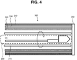
- FIG. 4 shows an assembled SEE endoscope 300 containing thereinside the SEE probe 200.
- the distal optics of the assembled probe 200 are arranged inside the inner diameter of the drive cable 310, for example, by bonding.
- the distal optics of probe 200 along with the drive cable 310 is rotated inside the inner sheath 320 by a non-illustrated torque generating motor located at the proximal end of the probe.
- detection fibers 330 are arranged around the outer surface of the inner sheath 320.
- an outer sheath 340 covers the detection fibers 330.
- a transparent window cover 350 is provided so as to cover at least the distal optics of the probe 200 and the detection fibers 330.
- fabrication errors can occur due to an accumulation of misalignments of the distal optics, or misalignment of the SEE probe 200 inside drive cable 310.
- appropriate alignment of the distal optics in probe 200 is important for high-quality imaging. However, even if care is taken to align the imaging fiber with the distal optics, it is unlikely that perfect alignment can be achieved and more likely that there will be some lateral and rotational misalignment between the fiber and the distal optical elements. This accumulation of small misalignments causes the spectrally encoded illumination line 110 to not pass trough the center of the field of view.
- Such fabrication error includes misalignment of the fiber 202 and lens 210, misalignment of the mirror surface 230 (e.g., due to errors in polishing), misalignment of the surface of grating 240 (e.g., due to errors in the fabrication of the spacer), misalignment in direction of the grating pattern, and misalignment of bonding the lens 210 and spacer 220.
- the grating 240 has 650 lines/mm groove density. In this case, 416nm light is diffracted in -6 th order in direction of the axis Ox of the probe 200 for blue color.
- the ratio 1:1.6 between pattern tilt and illumination line shift angles is calculated from equation (13), which is discussed in more detail below, for specific probe parameters. In other words, the ratio between pattern tilt and illumination line shift angles is different at different probe parameters.
- FIG. 5A shows the geometrical parameters in an example of the distal optics of the SEE probe 200, according to an embodiment.
- the distal optics includes the fiber 202 bonded to the lens 210, and the lens 210 in turn connected to the spacer 220.
- the spacer 220 includes the mirror surface 230 and the grating 240.
- the fiber 202 can be a single mode fiber or multimode fiber.
- the lens 210 can be a graded-index (GRIN) lens or a ball lens.
- the spacer 220 can be made of glass or molded plastic.
- broadband light is delivered from a non-illustrated light source, and the light guided to the GRIN lens 210.
- the light is then collimated by the lens 210 and a collimated beam is delivered on to the spacer 220.
- the spacer 220 can have a light reflecting surface, such as mirror surface 230.
- the mirror surface 230 can be made by polishing a part of the spacer or coating a part of the spacer with a reflective metal layer.
- the light beam traveling through the spacer 220 is incident on the mirror surface 230 at an angle larger than the critical angle with respect the mirror surface 230, and therefore the light incident on the surface 230 is completely reflected towards the grating 240.
- the grating 240 has a grating pattern formed on another surface of the spacer 220.
- the grating pattern can be made of glass or resin in a known manner.
- the light reflected at the mirror surface 230 is incident on the grating surface of the grating 240 and then diffracted towards a target sample (not shown).
- the diffracted light goes to the target sample as illumination light in spectrally encoded light having different wavelengths ( ⁇ 1 , ⁇ 2 , ⁇ 3 ) incident on different points of the target sample.
- the fiber can be a singlemode fiber or multimode fiber.
- the lens can be a GRIN lens or a ball lens.
- the spacer can be made of glass or plastic. Thought the fiber broadband light (or monochromatic light) is delivered from a light source to the lens.
- the grating 240 has 650 lines/mm groove density. In this case, 416nm light is diffracted in -6 th order in direction of the axis Ox of the probe 200 for blue color. For green and red color, 498nm and 621nm respectively, light is diffracted in -5 th and -4 th order in.
- FIG. 5A In the forward view SEE probe 200 shown in FIG. 5A , we define a Cartesian coordinate system (first coordinate system) x “, y", z " so that the probe optical axis is the z" axis, and the mirror normal and grating normal are in the x"-z” plane.
- FIG. 5B shows the Cartesian coordinate system (first coordinate system) x ", y", z ".
- second coordinate system x ', y', z', so that the z' axis is parallel to the grating surface normal, and the y' axis is parallel to y" axis.
- FIG. 5C shows the Cartesian coordinate system (second coordinate system) x', y' , z' .
- FIG. 6 shows the grating surface viewed from the normal to the surface of the grating 240.
- a third coordinate system x , y, z
- the grating lattice vector is parallel to the x axis
- the z axis is parallel to z' axis.
- the grating pattern x direction in Fig. 6
- the grating pattern is tilted by an angle ⁇ with respect to the x' direction.
- FIG. 7 shows the plane of incidence and the plane of diffracted light of the grating 240.
- a wave vector of a chief ray of an incident beam in the spacer 220 as k s
- a wave vector of the diffracted beam in air as k d .
- each component of vectors k s and k d in the coordinate system x , y, z as ( k sx ,k sy ,k sz ), and ( k dx ,k dy ,k dz ), respectively.
- Equation (10) the y" component of the diffracted light wave vector k dy" is given by Equation (10), where k dy" is not zero when ⁇ is not zero.
- k dx ⁇ 0
- ⁇ RLS can be approximated as ⁇ RLS ⁇ k dy ⁇ k d
- k dx ⁇ 0 ⁇ ⁇ ⁇ ⁇ mG ⁇ 0 ⁇ which means the rainbow lateral shift angle ⁇ RLS is proportional to the grating pattern inclination angle ⁇ .
- Table 1 shows parameters based on an exemplary design of a prototype color SEE probe fabricated by the applicant of the present application. Here, a simulation was performed to check rainbow curve shift of blue channel light with respect to the center of the field of view on the illumination plane.
- FIG. 8A shows the view angle of the rainbow curve calculated by Eq. ( 9 ).
- the wavelength range is 400 to 480 nm.
- the grating pattern tilt ⁇ is 0,0.5, 1.0, and 1.5 degrees.
- the view angle is measured from the probe axis ( z" ).
- the view angle is calculated as arctangent of k dy ⁇ k dz ⁇ , and k dx ⁇ k dz ⁇ for the y" and x" directions, respectively.
- x" is the spectrally encoding direction.
- FIG. 8B shows the angle of rainbow lateral shift ⁇ RLS for grating pattern tilt ⁇ calculated by Eq. ( 11 ), and its approximation calculated by Eq. ( 13 ).
- Eq. ( 13 ) is a good approximation to values calculated by Eq. ( 11 ).
- -mG ⁇ 0 is 1.62.
- the results show that when the grating pattern is tilted by 1 degree but the other probe/sheath parts are assembled as designed in the example described above, there will be a blind area (obscuration area) of 3.2 degrees in diameter at FOV center even if we correct the imaging data in post processing.
- FIGs. 8A and 8B indicate that there can be a blind area at the FOV center when the grating pattern is tilted.
- the same type of error would be expected with any other misalignment, as described above.
- one option could be to increase the precision of assembly to make the tolerance for the tilt as close to zero as possible. However, this solution will increase the fabrication time and costs.
- Another option is to compensate this tilt effect by changing other parts assembly angles.
- change ray angle from GRIN lens to the grating surface to satisfy k dy ⁇
- Another option is to tilt the probe optical axis from drive cable rotation axis by an angle of the rainbow lateral shift ⁇ RLS . Therefore, in the fabrication step, it would be advantageous to actively perform an alignment process where, for example, a laser beam can be introduced into the probe to aide in the alignment of the distal optics so as to ensure that the rainbow light from the probe can go through rotation axis direction. In both cases it is important to minimize grating pattern tilt because tilting parts by a large angle is not easy if the size of the endoscope is limited.
- the applicant has developed a simulation model for tilted grating pattern in forward view SEE imaging.
- the simulation results for an exemplary SEE color probe confirm that if the pattern is tilted and other parts are assembled as conventionally designed a blind area at the FOV center exists. Therefore, an alignment solution presented herein can avoid or at least minimize the obscuration of the center FOV, and therefore improved imaging results can be attained.
- the simulation model can be used to estimate a priori the amount of inclination (an alignment range) to ensure that no obscuration occurs at the center of the illumination FOV.
- FIGs. 9A and 9B show an example of an active alignment performed during the probe fabrication process of fixing the distal optics of probe 200 to the drive cable 310.
- FIGs. 10A and 10B show the field of view observed at the imaging plane during the active alignment process.
- FIG. 9A shows the illumination optics assembly of the probe 200 and the drive cable 310 viewed from the x direction in the x , y, z coordinate system.
- the illumination optics of probe 200 and drive cable 310 are aligned such that the drive cable axis 500 is parallel to (an concentric with) the axis Ox of the optical probe.
- spectrally encoded illumination line 510 does not pass the axis Ox of the illumination optics of probe 200.
- the illumination light at the field of view does not pass the drive cable axis 500, and thus it does not irradiate the area 140 around the center 120 of the scanned area 130, as shown in FIG. 10A .
- an active alignment is performed.
- a beam of light e.g., laser beam
- Wd working distance
- Mechanical retaining elements 960 and 962 used for aligning and securing (fixing) the optics of the probe 200 to the drive cable 310 can be prefabricated tubular structures or can be deposits of epoxy or resin that serve to hold one or more optical elements of the probe 200 at the desired angle.
- SEE optical probe 200 can be arranged such that the probe axis Ox is at an inclination angle ⁇ with respect to the axis 500 of the drive cable 310.
- the inclination angle can be obtained from the above-described inclination calculation and simulation. That is, a range of inclination angles and corresponding rainbow lateral shift angles, as those shown in FIGs. 8A and 8B , can be used to align the distal optics of the SEE probe in a manner to ensure that the illumination light arrives to the center of the field of view and obscuration is avoided.
- multiple monochromatic light sources which have different wavelengths can be used instead of using broadband light source.
- multiple light spots 610 (610a, 610b, 610c) which is light of a specific wavelength diffracted by the grating 240 appear on the screen or sensor as shown in FIG. 11A . From the spots 610, it is possible to estimate the location of spectrally encoded illumination line 110 which is diffracted light from the illumination optics of probe 200. Therefore, to ensure that no obscuration area remains in the field of view, as shown in FIG. 11B , we can tilt the illumination optics of probe 200 within the drive cable 310, as shown in FIG. 10B , until the spectrally encoded illumination line 110 passes the drive cable axis 500.
- one monochromatic light source can be used in the alignment above.
- the probe in FIG. 5A could generate blue light in -6th order, but at the same time there is light diffracted in other orders, for example, in -5th order and -4th order (shown as lambda1-3, respectively).
- one light spot 710 and two light spots 720 (720a, 720b) which are light diffracted in -6th order and -5th / -4th orders by the grating 240, respectively, appear on the screen or sensor as shown in FIG. 12A .
- the spots 710 and 720 it is possible to accurately estimate the location of spectrally encoded illumination line 110 which is diffracted light from the illumination optics of probe 200 when broadband light is input into the probe.
- the spectrally encoded illumination line 110 on the target sample can be a slightly curved. Any negative effects cause by this curve on the image can be safely and accurately compensated in post processing.
- SEE imaging using calibration chart which can have fixed pattern like grid we can figure out a relation between wavelength-time coordinates (data from spectrometer) and polar coordinates or Cartesian coordinates (processed image) for the curved illumination line.
- polar coordinates or Cartesian coordinates processed image
- a system 1300 to acquire an image using the SEE probe according to an exemplary embodiment of the present disclosure is shown in the diagram of FIG. 13 .
- the system 1300 of FIG. 13 includes, for example, a light source 1370, a detector/spectrometer 1380, a fiber optic rotary joint (FORJ) 1330, an imaging wand 1340, and an image processing computer 1350.
- the light source 1370 can be a supercontinuum laser or lamp that outputs light of broadband spectrum, or laser diode or an LED that outputs light of a single color or a narrow band spectrum, or a source of other electro-magnetic radiation.
- the range of the wavelength can be within the visible region, which is from about 400 nm thorough 800 nm. However, other wavelengths may also be used.
- the light can be directly guided or otherwise coupled into a source fiber, which may be referred to as an illumination fiber 1372.
- the illumination fiber 1372 can be connected to the FORJ 1330, and the light further guided to (and/or associated with) the illumination fiber 1302 of the imaging wand or SEE probe 1340.
- the SEE probe 1340 is connected at the proximal end thereof to the FORJ 1330.
- the SEE probe 1340 includes the illumination fiber 1302 and an assembly of distal optics 1315 arranged within a drive cable 1310; and the drive cable 1310 in turn is arranged within an outer sheath 1320.
- illumination light emitted from light source 1370 is delivered to the distal optics assembly 1315, and then diffracted by a grating onto a forward-viewing imaging plane.
- the light scattered back from an object or target sample e.g., tissue
- the detection fiber 1382 can be connected to the detector/spectrometer 1380 via a collimating or dispersing optical system 1384.
- the detector/spectrometer 1380 can detect the intensity of a selected wavelength. This exemplary function of detecting the selected wavelength can be performed by the spectrometer.
- Computer 1350 includes one or more microprocessors configured to control and operate the various parts of system 1300, by executing computer-executable instructions (program code). Computer 1350 can also be programmed to reconstruct images based on signals obtained from detector/spectrometer 1380.
- FIG. 14 a schematic block diagram of a control and processing system applicable to the system illustrated in FIG. 13 .
- the computer control system is representative of computer 1350 shown in FIG. 13 .
- the computer 1350 includes central processing unit (CPU) 1401, a storage memory (RAM) 1402, a user input/output (I/O) interface 1403, and a system interface 1404.
- the computer 1350 illustrated in FIG. 14 can issue a command that can be transmitted to the imaging system 1300 via the system interface 1404.
- a touch panel screen can be included as part of the user interface unit/imaging processor, in addition a key board, mouse, joy-stick, ball controller, and foot pedal can also be included as part of the user interface.
- the user can cause a command to be initiated to observe inside a lumen of the human body through the exemplary front-view SEE probe using the user interface unit/imaging processor. For example, when the user inputs a command via the user interface 1403, the command is transmitted to the central processing unit CPU 1401 for execution thereby causing the CPU to issue a command via the system interface 1404 to one or more of the light source 1370, the detector/spectrometer 1380, or the FORJ 1330.
- the CPU 1401 is comprised of one or more processors (microprocessors) configured to read and perform computer-executable instructions stored in the storage memory 1402.
- the computer-executable instructions may include program code for the performance of the novel processes, methods and/or calculations disclosed herein.
- the computer 1350 functions as imaging processor that can be programmed to apply exemplary image processing such as noise reduction, coordinate distortion correction, contrast enhancement and so on. After or even during the image processing is performed, the data can be transmitted from the imaging processor to a display (not shown).
- a liquid crystal display (LCD) can be the display.
- the display can display, for example, the individual images obtained from a single color or a composite color image according to the various exemplary embodiments of the present disclosure.
- the display can also display other information than the image, such as the date of observation, what part of the human body is observed, the patient's name, operator's name and so on.
- the CPU 1401 is configured to read and perform computer-executable instructions stored in the Storage/RAM 1402.
- the computer-executable instructions may include those for the performance of the methods and/or calculations described herein.
- CPU 1401 may calculate the angular momentum or speed of rotation of the SEE probe, and can use that information (rotation speed or angular momentum) to operate the FORJ. In this manner, computer 1350 can obtain a new set of images where their angular positions are corrected.
- Storage/RAM 1402 includes one or more computer readable and/or writable media, and may include, for example, a magnetic disc (e.g., a hard disk), an optical disc (e.g., a DVD, a Blu-ray), a magneto-optical disk, semiconductor memory (e.g., a non-volatile memory card, flash memory, a solid state drive, SRAM, DRAM), an EPROM, an EEPROM, etc.
- Storage/RAM 1402 may store computer-readable data and/or computer-executable instructions. The components of the processor may communicate via a bus.
- the system I/O interface 1404 provides communication interfaces to input and output devices, which may include a keyboard, a display, a mouse, a printing device, a touch screen, a light pen, an optical storage device, a scanner, a microphone, a camera, a drive, communication cable and a network (either wired or wireless).
- input and output devices may include a keyboard, a display, a mouse, a printing device, a touch screen, a light pen, an optical storage device, a scanner, a microphone, a camera, a drive, communication cable and a network (either wired or wireless).
- the system I/O interface 1404 also provides communication interfaces to input and output devices.
- the detector may include, for example a photomultiplier tube (PMT), a photodiode, an avalanche photodiode detector (APD), a charge-coupled device (CCD), multi-pixel photon counters (MPPC), or other.
- PMT photomultiplier tube
- APD avalanche photodiode detector
- CCD charge-coupled device
- MPPC multi-pixel photon counters
- the function of detector may be realized by computer executable instructions (e.g., one or more programs) recorded on a Storage/RAM 1402.
- the user can place the exemplary SEE probe into a sheath, and then can insert such arrangement/configuration into a predetermined position of a human body.
- the sheath alone may be inserted into the human body in advance, and it is possible to insert the SEE probe into the sheath after sheath insertion.
- the exemplary probe can be used to observe inside human body and works as an endoscope such as arthroscopy, bronchoscope, sinuscope, vascular endoscope and so on.
- spatially relative terms such as “under” “beneath”, “below”, “lower”, “above”, “upper”, “proximal”, “distal”, and the like, may be used herein for ease of description to describe one element or feature's relationship to another element(s) or feature(s) as illustrated in the various figures. It should be understood, however, that the spatially relative terms are intended to encompass different orientations of the device in use or operation in addition to the orientation depicted in the figures. For example, if the device in the figures is turned over, elements described as “below” or “beneath” other elements or features would then be oriented “above” the other elements or features. Thus, a relative spatial term such as “below” can encompass both an orientation of above and below.
- the device may be otherwise oriented (rotated 90 degrees or at other orientations) and the spatially relative descriptors used herein are to be interpreted accordingly. Similarly, the relative spatial terms “proximal” and “distal” may also be interchangeable, where applicable.
- first, second, third, etc. may be used herein to describe various elements, components, regions, parts and/or sections. It should be understood that these elements, components, regions, parts and/or sections should not be limited by these terms. These terms have been used only to distinguish one element, component, region, part, or section from another region, part, or section. Thus, a first element, component, region, part, or section discussed below could be termed a second element, component, region, part, or section without departing from the teachings herein.
- a forward-viewing spectrally encoded endoscope (SEE) probe includes a light guiding component, a light focusing component, and a grating component arranged along a longitudinal axis of a drive cable.
- the SEE probe is configured for guiding light from the light guiding component, through the light focusing component, and to the grating component, and then forwarding a spectrally dispersed light line from the grating component towards an image plane.
- One or more of the light guiding component, the light focusing component, and the grating component is arranged at an angle with respect to the longitudinal axis of the drive cable so that at least one wavelength of the spectrally dispersed light line goes to the direction of axis of the drive cable.
Landscapes
- Health & Medical Sciences (AREA)
- Life Sciences & Earth Sciences (AREA)
- Surgery (AREA)
- Physics & Mathematics (AREA)
- Optics & Photonics (AREA)
- Engineering & Computer Science (AREA)
- Biomedical Technology (AREA)
- Veterinary Medicine (AREA)
- Pathology (AREA)
- Radiology & Medical Imaging (AREA)
- Biophysics (AREA)
- Nuclear Medicine, Radiotherapy & Molecular Imaging (AREA)
- Public Health (AREA)
- Heart & Thoracic Surgery (AREA)
- Medical Informatics (AREA)
- Molecular Biology (AREA)
- Animal Behavior & Ethology (AREA)
- General Health & Medical Sciences (AREA)
- General Physics & Mathematics (AREA)
- Astronomy & Astrophysics (AREA)
- Signal Processing (AREA)
- Manufacturing & Machinery (AREA)
- Instruments For Viewing The Inside Of Hollow Bodies (AREA)
- Endoscopes (AREA)
Applications Claiming Priority (1)
| Application Number | Priority Date | Filing Date | Title |
|---|---|---|---|
| US15/969,298 US10314469B1 (en) | 2018-05-02 | 2018-05-02 | Spectrally encoded probes |
Publications (1)
| Publication Number | Publication Date |
|---|---|
| EP3569136A1 true EP3569136A1 (en) | 2019-11-20 |
Family
ID=65818433
Family Applications (1)
| Application Number | Title | Priority Date | Filing Date |
|---|---|---|---|
| EP19163628.1A Withdrawn EP3569136A1 (en) | 2018-05-02 | 2019-03-19 | Probe with a grating arranged inside a drive cable and a method for alignment of optics in an endoscopic probe |
Country Status (3)
| Country | Link |
|---|---|
| US (1) | US10314469B1 (https=) |
| EP (1) | EP3569136A1 (https=) |
| JP (1) | JP6720379B2 (https=) |
Families Citing this family (1)
| Publication number | Priority date | Publication date | Assignee | Title |
|---|---|---|---|---|
| WO2020163449A1 (en) | 2019-02-05 | 2020-08-13 | Canon U.S.A., Inc. | Endoscope observation window cleaning |
Citations (16)
| Publication number | Priority date | Publication date | Assignee | Title |
|---|---|---|---|---|
| US6341036B1 (en) | 1998-02-26 | 2002-01-22 | The General Hospital Corporation | Confocal microscopy with multi-spectral encoding |
| US20080013960A1 (en) | 2000-11-10 | 2008-01-17 | The General Hospital Corporation | Apparatus and method for providing information for at least one structure |
| US7796270B2 (en) | 2006-01-10 | 2010-09-14 | The General Hospital Corporation | Systems and methods for generating data based on one or more spectrally-encoded endoscopy techniques |
| US7843572B2 (en) | 2005-09-29 | 2010-11-30 | The General Hospital Corporation | Method and apparatus for optical imaging via spectral encoding |
| US7859679B2 (en) | 2005-05-31 | 2010-12-28 | The General Hospital Corporation | System, method and arrangement which can use spectral encoding heterodyne interferometry techniques for imaging |
| US20110237892A1 (en) | 2008-07-14 | 2011-09-29 | The General Hospital Corporation | Apparatus and methods for color endoscopy |
| US8045177B2 (en) | 2007-04-17 | 2011-10-25 | The General Hospital Corporation | Apparatus and methods for measuring vibrations using spectrally-encoded endoscopy |
| US8145018B2 (en) | 2006-01-19 | 2012-03-27 | The General Hospital Corporation | Apparatus for obtaining information for a structure using spectrally-encoded endoscopy techniques and methods for producing one or more optical arrangements |
| US8780176B2 (en) | 2008-08-15 | 2014-07-15 | Technion Research & Development Foundation Limited | Vessel imaging system and method |
| US8812087B2 (en) | 2009-06-16 | 2014-08-19 | Technion Research & Development Foundation Limited | Method and system of spectrally encoded imaging |
| WO2015116939A1 (en) | 2014-01-31 | 2015-08-06 | Canon U.S.A., Inc. | Apparatus and methods for color endoscopy |
| WO2015116951A2 (en) | 2014-01-31 | 2015-08-06 | Canon U.S.A., Inc. | Optical probe, light intensity detection, imaging method and system |
| WO2017024145A1 (en) * | 2015-08-05 | 2017-02-09 | Canon U.S.A., Inc. | Forward and angle view endoscope |
| WO2018001791A1 (fr) * | 2016-06-30 | 2018-01-04 | Teledyne E2V Semiconductors Sas | Capteur lineaire pour appareil d'imagerie de tomographie par coherence optique a spectrometre |
| US20180017778A1 (en) * | 2016-07-15 | 2018-01-18 | Canon U.S.A., Inc. | Spectrally Encoded Probe with Multiple Diffraction Orders |
| WO2018013838A1 (en) * | 2016-07-15 | 2018-01-18 | Canon U.S.A. Inc. | Spectrally encoded probes |
Family Cites Families (8)
| Publication number | Priority date | Publication date | Assignee | Title |
|---|---|---|---|---|
| JP4117616B2 (ja) | 2003-07-28 | 2008-07-16 | ソニー株式会社 | 編集システム、その制御方法及び編集装置 |
| EP2316328B1 (en) | 2003-09-15 | 2012-05-09 | Super Dimension Ltd. | Wrap-around holding device for use with bronchoscopes |
| JP2009070545A (ja) * | 2007-08-23 | 2009-04-02 | Hoya Corp | 光ピックアップ装置 |
| WO2011044301A2 (en) * | 2009-10-06 | 2011-04-14 | The General Hospital Corporation | Apparatus and methods for imaging particular cells including eosinophils |
| US8467430B2 (en) * | 2010-09-23 | 2013-06-18 | Daylight Solutions, Inc. | Continuous wavelength tunable laser source with optimum orientation of grating and gain medium |
| US20140221747A1 (en) * | 2013-02-01 | 2014-08-07 | The General Hospital Corporation | Apparatus, systems and methods which include and/or utilize flexible forward scanning catheter |
| WO2017139657A1 (en) | 2016-02-12 | 2017-08-17 | Canon U.S.A., Inc. | Simple monolithic optical element for forward-viewing spectrally encoded endoscopy |
| JP2019534069A (ja) * | 2016-09-23 | 2019-11-28 | キヤノン ユーエスエイ, インコーポレイテッドCanon U.S.A., Inc | スペクトル符号化内視鏡検査装置および方法 |
-
2018
- 2018-05-02 US US15/969,298 patent/US10314469B1/en active Active
-
2019
- 2019-03-19 EP EP19163628.1A patent/EP3569136A1/en not_active Withdrawn
- 2019-04-11 JP JP2019075552A patent/JP6720379B2/ja active Active
Patent Citations (16)
| Publication number | Priority date | Publication date | Assignee | Title |
|---|---|---|---|---|
| US6341036B1 (en) | 1998-02-26 | 2002-01-22 | The General Hospital Corporation | Confocal microscopy with multi-spectral encoding |
| US20080013960A1 (en) | 2000-11-10 | 2008-01-17 | The General Hospital Corporation | Apparatus and method for providing information for at least one structure |
| US7859679B2 (en) | 2005-05-31 | 2010-12-28 | The General Hospital Corporation | System, method and arrangement which can use spectral encoding heterodyne interferometry techniques for imaging |
| US7843572B2 (en) | 2005-09-29 | 2010-11-30 | The General Hospital Corporation | Method and apparatus for optical imaging via spectral encoding |
| US7796270B2 (en) | 2006-01-10 | 2010-09-14 | The General Hospital Corporation | Systems and methods for generating data based on one or more spectrally-encoded endoscopy techniques |
| US8145018B2 (en) | 2006-01-19 | 2012-03-27 | The General Hospital Corporation | Apparatus for obtaining information for a structure using spectrally-encoded endoscopy techniques and methods for producing one or more optical arrangements |
| US8045177B2 (en) | 2007-04-17 | 2011-10-25 | The General Hospital Corporation | Apparatus and methods for measuring vibrations using spectrally-encoded endoscopy |
| US20110237892A1 (en) | 2008-07-14 | 2011-09-29 | The General Hospital Corporation | Apparatus and methods for color endoscopy |
| US8780176B2 (en) | 2008-08-15 | 2014-07-15 | Technion Research & Development Foundation Limited | Vessel imaging system and method |
| US8812087B2 (en) | 2009-06-16 | 2014-08-19 | Technion Research & Development Foundation Limited | Method and system of spectrally encoded imaging |
| WO2015116939A1 (en) | 2014-01-31 | 2015-08-06 | Canon U.S.A., Inc. | Apparatus and methods for color endoscopy |
| WO2015116951A2 (en) | 2014-01-31 | 2015-08-06 | Canon U.S.A., Inc. | Optical probe, light intensity detection, imaging method and system |
| WO2017024145A1 (en) * | 2015-08-05 | 2017-02-09 | Canon U.S.A., Inc. | Forward and angle view endoscope |
| WO2018001791A1 (fr) * | 2016-06-30 | 2018-01-04 | Teledyne E2V Semiconductors Sas | Capteur lineaire pour appareil d'imagerie de tomographie par coherence optique a spectrometre |
| US20180017778A1 (en) * | 2016-07-15 | 2018-01-18 | Canon U.S.A., Inc. | Spectrally Encoded Probe with Multiple Diffraction Orders |
| WO2018013838A1 (en) * | 2016-07-15 | 2018-01-18 | Canon U.S.A. Inc. | Spectrally encoded probes |
Non-Patent Citations (3)
| Title |
|---|
| C. PITRIS ET AL., OPTICAL EXPRESS, vol. 11, 2003, pages 120 - 124 |
| D. YELIN ET AL., THREE-DIMENSIONAL MINIATURE ENDOSCOPY'', NATURE, vol. 443, 2006, pages 765 - 765 |
| G. TEARNEY ET AL.: "Spectrally encoded miniature endoscopy", OPT. LETT., vol. 27, no. 6, 2002, pages 412 - 414, XP001117234 |
Also Published As
| Publication number | Publication date |
|---|---|
| JP2019217260A (ja) | 2019-12-26 |
| US10314469B1 (en) | 2019-06-11 |
| JP6720379B2 (ja) | 2020-07-08 |
Similar Documents
| Publication | Publication Date | Title |
|---|---|---|
| EP3099214B1 (en) | Forward viewing endoscopic probe and system | |
| US10234694B2 (en) | Spectrally encoded probes | |
| US9864140B2 (en) | Miniature optical elements for fiber-optic beam shaping | |
| EP3010389B1 (en) | Omni-directional viewing apparatus and method | |
| US10606064B2 (en) | Optical probes with astigmatism correction | |
| US10816789B2 (en) | Optical probes that include optical-correction components for astigmatism correction | |
| CN100488440C (zh) | 共路型内窥光学相干层析成像方法及系统 | |
| US10234676B1 (en) | Optical probes with reflecting components for astigmatism correction | |
| US20230324603A1 (en) | Multicore Fiber with Distal Motor | |
| US10321810B2 (en) | Spectrally encoded endoscopic probe having a fixed fiber | |
| JP2000097846A (ja) | 光走査プローブ装置 | |
| US11497382B1 (en) | Apparatus and method for endoscopic image orientation control | |
| JP2019502519A (ja) | 光プローブ、光強度検出、撮像方法およびシステム | |
| US10806329B2 (en) | Optical probes with optical-correction components | |
| US20200154985A1 (en) | Endoscopic probe having rotating core with built-in encoder | |
| US10222607B2 (en) | Three-dimensional endoscope | |
| CN111436908B (zh) | 光学相干断层成像内窥探头及成像系统 | |
| US10314469B1 (en) | Spectrally encoded probes | |
| CN201101518Y (zh) | 共路型内窥光学相干层析成像系统 | |
| US10794732B2 (en) | Apparatus, system and method for correcting nonuniform rotational distortion in an image comprising at least two stationary light transmitted fibers with predetermined position relative to an axis of rotation of at least one rotating fiber |
Legal Events
| Date | Code | Title | Description |
|---|---|---|---|
| PUAI | Public reference made under article 153(3) epc to a published international application that has entered the european phase |
Free format text: ORIGINAL CODE: 0009012 |
|
| STAA | Information on the status of an ep patent application or granted ep patent |
Free format text: STATUS: THE APPLICATION HAS BEEN PUBLISHED |
|
| AK | Designated contracting states |
Kind code of ref document: A1 Designated state(s): AL AT BE BG CH CY CZ DE DK EE ES FI FR GB GR HR HU IE IS IT LI LT LU LV MC MK MT NL NO PL PT RO RS SE SI SK SM TR |
|
| AX | Request for extension of the european patent |
Extension state: BA ME |
|
| STAA | Information on the status of an ep patent application or granted ep patent |
Free format text: STATUS: REQUEST FOR EXAMINATION WAS MADE |
|
| 17P | Request for examination filed |
Effective date: 20200519 |
|
| STAA | Information on the status of an ep patent application or granted ep patent |
Free format text: STATUS: EXAMINATION IS IN PROGRESS |
|
| 17Q | First examination report despatched |
Effective date: 20200907 |
|
| STAA | Information on the status of an ep patent application or granted ep patent |
Free format text: STATUS: THE APPLICATION IS DEEMED TO BE WITHDRAWN |
|
| 18D | Application deemed to be withdrawn |
Effective date: 20210715 |