EP3569100B1 - Backpack with dynamic flexible hip belt - Google Patents
Backpack with dynamic flexible hip belt Download PDFInfo
- Publication number
- EP3569100B1 EP3569100B1 EP19174561.1A EP19174561A EP3569100B1 EP 3569100 B1 EP3569100 B1 EP 3569100B1 EP 19174561 A EP19174561 A EP 19174561A EP 3569100 B1 EP3569100 B1 EP 3569100B1
- Authority
- EP
- European Patent Office
- Prior art keywords
- panel
- resilient
- hip belt
- backpack
- edge portion
- Prior art date
- Legal status (The legal status is an assumption and is not a legal conclusion. Google has not performed a legal analysis and makes no representation as to the accuracy of the status listed.)
- Active
Links
Images





Classifications
-
- A—HUMAN NECESSITIES
- A45—HAND OR TRAVELLING ARTICLES
- A45F—TRAVELLING OR CAMP EQUIPMENT: SACKS OR PACKS CARRIED ON THE BODY
- A45F3/00—Travelling or camp articles; Sacks or packs carried on the body
- A45F3/04—Sacks or packs carried on the body by means of two straps passing over the two shoulders
-
- A—HUMAN NECESSITIES
- A45—HAND OR TRAVELLING ARTICLES
- A45F—TRAVELLING OR CAMP EQUIPMENT: SACKS OR PACKS CARRIED ON THE BODY
- A45F3/00—Travelling or camp articles; Sacks or packs carried on the body
- A45F3/04—Sacks or packs carried on the body by means of two straps passing over the two shoulders
- A45F3/047—Sacks or packs carried on the body by means of two straps passing over the two shoulders with adjustable fastenings for the shoulder straps or waist belts
-
- A—HUMAN NECESSITIES
- A45—HAND OR TRAVELLING ARTICLES
- A45F—TRAVELLING OR CAMP EQUIPMENT: SACKS OR PACKS CARRIED ON THE BODY
- A45F3/00—Travelling or camp articles; Sacks or packs carried on the body
- A45F3/04—Sacks or packs carried on the body by means of two straps passing over the two shoulders
- A45F3/08—Carrying-frames; Frames combined with sacks
-
- A—HUMAN NECESSITIES
- A45—HAND OR TRAVELLING ARTICLES
- A45F—TRAVELLING OR CAMP EQUIPMENT: SACKS OR PACKS CARRIED ON THE BODY
- A45F3/00—Travelling or camp articles; Sacks or packs carried on the body
- A45F3/04—Sacks or packs carried on the body by means of two straps passing over the two shoulders
- A45F2003/045—Sacks or packs carried on the body by means of two straps passing over the two shoulders and one additional strap around the waist
Definitions
- the technology described herein relates generally to backpacks and, more specifically, to hip belt assemblies for backpacks.
- Backpacks have long been used to carry heavy, bulky loads.
- backpacks often include a hip belt attached to a lower portion of the sack to facilitate in distributing the weight of the load onto a wearer in a desirable manner.
- a hip belt transfers some of the load onto the hips and lumbar area of a wearer, and can reduce the load applied to the user's shoulders, thus allowing the wearer to carry a heavy load in relative comfort.
- a hip belt is attached to a lower portion of the backpack, extending about the hips of the wearer.
- Many hip belts include padding to add comfort on the wearer's hip and back, and buckles in the front to secure the hip belt around the wearer's waist.
- Many hip belts are rigidly attached to the backpack causing the weight of the backpack to shift as a wearer moves. A shifting load may cause overloading to concentrated areas on the wearer, and cause discomfort.
- hip belts have been configured with mechanical adjustments to facilitate the relative movement between the sack and the hip belt.
- many of these mechanical adjustments do not allow the hip belt to move sufficiently relative to the sack of the backpack given the wearer's movements.
- the load still tends to shift an undesirable amount relative to the wearer's hips.
- mechanical attachments of the hip belt may be bulky, complex, and difficult to manufacture.
- hip belt assembly It is therefore desirable to provide an improved hip belt assembly, and, more specifically, to provide a simple and resilient hip belt assembly that can conform to a wearer's movements while providing effective load distribution.
- Documents that may be related to the present disclosure include AT180637 T , AU2705797 A , AU3900397 A , AU3507597 A , AU1969883 A , AU765141 B2 , CA1044197 A , CA2861974 A1 , CA2262641 A1 , CA2258870 A1 , CN106535705 A , CN1225559 A , DE10025154 A1 , DE873065T1 , DE29723060 U1 , DE19781908 T1 , DE104538T1 , DE3375366 D1 , DE69700254 D1 , DE69700254 T2 , EP3136903 A1 , EP0873065 A1 , EP0873065 B1 , EP0104538 B1 , EP0923325 A1 , EP0628265 A1 , GB2525662 A , GB2350286 B , IES71158 B2
- the present disclosure provides a backpack with a flexible hip belt assembly, as described below and defined in the accompanying claims.
- the backpack includes a frame assembly which may support the structure of the backpack, including a sack for holding articles; a hip belt which may be coupled to the backpack for distributing the weight of a load to a wearer, and one or more resilient panels resiliently coupling the hip belt to the frame assembly.
- the frame assembly may include a back panel assembly that interfaces with a wearer, a frame member coupled to the back panel assembly, and a support panel operably coupled to the frame member.
- the back panel assembly may include a back panel dividing the front and back of the backpack, and a suspension panel that is spaced away from the back panel.
- a backpack (100) comprising: a frame assembly (102); a hip belt (122) including a central portion (124), the central portion (124) having opposing first and second arms (126, 128) extending outwardly from opposing right and left lateral portions (185, 184) of the central portion, the central portion having opposing lateral portions; at least one resilient panel (118, 120) coupling the hip belt (122) to the frame assembly (102), wherein the at least one resilient panel (118, 120) defines opposing upper and lower edge portions (154, 156), and opposing interior and exterior side edge portions (148, 146); and said at least one resilient panel (118, 120) expands or contracts as the hip belt (122) and frame assembly (102) move relative to one another to reduce forces applied to the hip belt (122) by non-vertical movement of the frame assembly (102), wherein a bottom edge portion of the hip belt (122) couples to the frame assembly (102) forming a load bearing seam to support a substantially vertical load applied between the frame assembly (102) and the hip belt (122).
- the frame assembly may include a back panel assembly defining opposing first and second side edge portions.
- the frame assembly may also include a frame member disposed about a perimeter of the back panel assembly. The at least part of at least one of the upper edge portion and exterior side edge portion of the at least one resilient panel may be attached to at least one of the back panel assembly and the frame member.
- the back panel assembly may include a back panel defining opposing first and second side edge portions.
- the back panel assembly may also include a suspension panel coupled to at least an upper portion of the back panel and spaced apart from the back panel.
- the suspension panel may include a bottom edge portion. The at least part of at least one of the upper edge portion and exterior side edge portion of the at least one resilient member may be attached to at least one of the back panel and the suspension panel.
- An entire length of the exterior side edge portion of the at least one resilient member may be attached to at least one of the back panel assembly and the frame member.
- An entire length of the top edge portion of the at least one resilient member may be attached to at least a portion of the bottom edge portion of the suspension panel.
- At least a portion of the interior side edge portion of the at least one resilient member may be extended along and coupled to at least a portion of a height of an adjacent lateral edge portion of the central portion of the load support assembly.
- the interior side edge portion in one example, may extend along and be coupled to the entirety of the height of the central portion of the load support assembly.
- a bottom edge portion of the load support assembly may couple to the frame assembly forming a load bearing seam.
- a bottom portion of the at least one resilient member may be coupled to an anchor.
- the anchor may limit rotation and flex at the bottom portion of the resilient panel.
- the at least one resilient member When force is applied to the load support assembly, the at least one resilient member may stretch in a direction of the applied force. When the applied force is removed, the at least one resilient member may substantially return to an original position.
- the at least one resilient member may form an elongated panel adjacent to the load support assembly.
- the at least one resilient member may include two laterally spaced resilient panels positioned on opposite sides of the central portion of the load support assembly.
- the at least one resilient member may include at least two elastic fabric panels.
- the at least one resilient member may include at least one strap.
- a backpack having a frame assembly, a load support member including a central portion, and at least one resilient member coupling the frame assembly to the load support member.
- the at least one resilient member may have a length and a width and may form a flat and elongated shape.
- the at least one resilient member may stretch along the length and the width.
- the at least one resilient member may also include two laterally spaced resilient members positioned on opposite sides of the central portion of the load support member.
- the at least one resilient member may also transition between a first state and a second state as the load support member and frame assembly move relative to one another to reduce the forces applied to the load support member by the non-vertical movement of the frame assembly.
- Additional examples or embodiments not according to the invention may include a backpack having a load supporting belt having a top edge and at least one side edge, and a suspension panel having a bottom portion.
- the backpack may also include at least one resilient member with a first edge and a second edge. Each edge may define a length.
- the at least one resilient member may couple to at least one of the top edge and the at least one side edge of the load supporting belt along at least a portion of the length of the first edge.
- the at least one resilient member may also couple to the bottom portion of the suspension panel along at least a portion of the length of the second edge.
- the load supporting belt may have a bottom edge
- the backpack may include a frame assembly, wherein the bottom edge of the load supporting belt is coupled to a bottom portion of the frame assembly forming a load bearing engagement.
- Additional examples or embodiments of the present disclosure may include a resilient hip belt for a backpack.
- the hip belt may include two arms extending from a central portion.
- the central portion may have opposing lateral portions.
- Two laterally spaced resilient members may be positioned on opposite sides of the central portion of the hip belt. When a force is applied to the hip belt, the resilient members stretch in a direction of the applied force. When the applied force is removed, the resilient members substantially return to an original position.
- the backpack may include a frame assembly.
- the backpack may include a hip belt.
- the hip belt may include a central portion.
- the central portion may have opposing first and second arms extending from the central portion and opposing lateral portions.
- At least one resilient panel may couple the hip belt to the frame assembly.
- the at least one resilient panel may define opposing upper and lower edge portions, and opposing interior and exterior side edge portions.
- the at least one resilient panel may expand or contract as the hip belt and frame assembly move relative to one another to reduce forces applied to the hip belt by non-vertical movement of the frame assembly.
- the at least one resilient panel may form an elongated panel coupling the hip belt to the frame assembly.
- the at least one resilient panel may include two laterally spaced resilient panels each coupled between the frame assembly and the central portion of the hip belt.
- the relative movement of the hip belt and the frame assembly may be at least one of a rotational motion and a twisting motion.
- the relative movement of the hip belt and the frame assembly may be at least a pivoting motion (e.g. such as movement about a point or points in a curved path).
- At least a part of the interior side edge portion of the at least one resilient panel may be attached to the hip belt and at least part of at least one of the upper edge portion and exterior side edge portion may be attached to the frame assembly.
- the frame assembly may include a back panel assembly.
- the back panel assembly may define opposing first and second side edge portions.
- the frame assembly may include a frame member disposed about a perimeter of the back panel assembly. The at least part of at least one of the upper edge portion and exterior side edge portion of the at least one resilient panel may be attached to at least one of the back panel assembly and the frame member.
- the back panel assembly may include a back panel.
- the back panel may define opposing first and second side edge portions.
- the at least part of at least one of the upper edge portion and exterior side edge portion of the at least one resilient panel may be attached to the back panel.
- the back panel assembly may include a suspension panel coupled to at least an upper portion of the back panel and spaced apart from the back panel.
- the suspension panel may include a bottom edge portion. The at least part of at least one of the upper edge portion and exterior side edge portion of the at least one resilient panel may be attached to at least one of the back panel and the suspension panel.
- An entire length of the exterior side edge portion of the at least one resilient panel may be attached to at least one of the back panel assembly and the frame member.
- An entire length of the upper edge portion of the at least one resilient panel may be attached to at least a portion of the bottom edge portion of the suspension panel.
- At least a portion of the interior side edge portion of the at least one resilient panel may extend along and be coupled to at least a portion of a height of an adjacent lateral portion of the central portion of the hip belt.
- the interior side edge portion may extend along and be coupled to the entirety of a height of the adjacent lateral portion of the central portion of the hip belt.
- the at least one resilient panel When force is applied to the hip belt, the at least one resilient panel may stretch in a direction of the applied force, and when the applied force is removed, the at least one resilient panel may substantially return to an original position.
- the backpack may include a frame assembly.
- the backpack may include a hip belt including a central portion.
- the backpack may include at least one resilient member coupling the frame assembly to the hip belt.
- the at least one resilient member may have a length and a width and may define a flat and elongated shape.
- the at least one resilient member may be stretchable along the length and the width.
- the at least one resilient member may include two laterally spaced resilient members positioned on opposite sides of the central portion of the hip belt. Additionally or separately, the at least one resilient member may include at least one strap.
- the at least one resilient member may transition between a first state and a second state as the hip belt and the frame assembly move relative to one another to reduce the forces applied to the hip belt by non-vertical movement of the frame assembly.
- the backpack may include a hip belt having a top edge portion and at least one side edge portion.
- the backpack may include a suspension panel having a bottom portion.
- the backpack may include at least one resilient member with a first edge portion and a second edge portion. Each edge portion may define a length.
- the at least one resilient member may couple to at least one of the top edge portion and the at least one side edge portion of the hip belt along at least a portion of the length of the first edge portion.
- the at least one resilient member may couple to the bottom portion of the suspension panel along at least a portion of the length of the second edge portion.
- the hip belt may have a bottom edge portion.
- the backpack may further include a frame assembly.
- the bottom edge portion of the hip belt may be coupled to a bottom portion of the frame assembly forming a load bearing engagement to support a substantially vertical load applied between the frame assembly and the hip belt.
- the backpack may include a cargo bag or sack, a frame assembly, a resilient panel, and a hip belt.
- the frame assembly may include a frame member, a back panel assembly, and a support panel.
- the back panel assembly may include several panels or layers, including a back panel and a suspension panel.
- the hip belt is resiliently coupled to the frame assembly by the resilient panel. The resilient panel expands and contracts as the hip belt and frame assembly move relative to one another to reduce the forces applied to the hip belt by the non-vertical movement of the frame assembly.
- the resilient panel at least in part couples the hip belt to the frame assembly to generally isolate the movement of the hip belt from the movement of the frame assembly. Since the hip belt engages a wearer's hip region, the hip belt moves with the wearer's hips.
- the frame assembly supports the cargo bag, which may include a cargo load of up to 50 or more pounds.
- the frame assembly then includes a load that creates a moment force generally about the attachment between the hip belt and the frame assembly. This cargo load moves, such as swaying, and has an associated momentum that can be transmitted through a traditional connection structure between a frame assembly and a hip belt, and then to the wearer, which can create undesirable effects.
- connection structure between the hip belt and the frame assembly disclosed here, and, in particular, the resilient panels as used in this structure allows the hip belt and frame assembly to move relative to each other to at least partially de-link the movement of the cargo load from the motion of the hip belt.
- This result is referred to herein as "hip belt flexibility.”
- This de-linking reduces the undesirable forces applied by the moving cargo load to a wearer through the hip belt.
- the resilient panel provides a simplified approach to improving hip belt flexibility that has functional and commercial advantages over the more complex existing systems.
- FIG. 1 is a perspective view of a backpack 100 in accordance with one embodiment, depicting a hip belt 122 with a resilient attachment to a frame assembly 102.
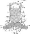
- FIG. 2A is a front elevation view of the backpack 100 of FIG. 1 with the shoulder straps 162 removed.
- FIG. 3 is a perspective partially exploded view of the backpack 100 of FIG. 2A , showing the back panel 108, suspension panel 110, resilient panels 118, 120, and hip belt 122. As shown in FIGS.
- the backpack 100 may include a frame assembly 102, a hip belt 122, one or more resilient panels 118, 120, a bottom panel 130, one or more cover panels 170, 171, and other common backpack features, such as a sack 160, shoulder straps 162, one or more handles 164, buckles 166, adjustment straps 168, and the like.
- the sack 160 is supported on the frame assembly 102, which may include a back panel assembly 104, a frame member 106, and a support panel 116.
- the back panel assembly 104 is positioned on the back side of the backpack 100, i.e. the side that faces a wearer's back.
- the back panel assembly 104 may be made up of one or more panels or layers.
- the back panel assembly 104 may include one or more of a back panel 108, a foam layer 115, and a suspension panel 110.
- the back panel 108 is the panel closest to the front side of the backpack 100 in the back panel assembly 104.
- the back panel 108 may be of any shape that is compatible to engage with a wearer's back and support a sack for carrying cargo.
- the back panel 108 may be an oval shape, a rectangular shape, or the like, and may be curved or flat.
- the back panel 108 is a generally flat rectangular shape with a top edge portion 144, a bottom edge portion 174, and opposing first and second side edge portions 140, 142.
- the back panel 108 may be made of a variety of materials, such as man-made (e.g. nylon), natural materials (e.g. cotton, leather) or a combination.
- the back panel assembly 104 may also include a suspension or float panel 110.
- the suspension panel 110 defines a central body defining a peripheral edge. At least a portion or a plurality of portions of the peripheral edge are secured to the edge portions 140, 142, 144, 174 of the back panel 108, and the central body is spaced away from the back panel 108.
- the suspension panel 110 is configured to contact a wearer's back.
- the suspension panel 110 may be any shape configured to run along at least a portion of the length of the wearer's back, and the shape of the suspension panel 110 may vary with the shape of the backpack 100 and the back panel 108 in particular.
- the suspension panel 110 is smaller than the back panel 108, and, in this example, does not extend beyond the top, bottom and opposing side edge portions 144, 174, 140, 142 of the back panel 108.
- the suspension panel 110 shown in the figures has a first side edge portion 136, a second side edge portion 138, a top edge portion 132 in a concave curved shape and a bottom edge portion 134 having a convex curved shape.
- the top edge portion 132 and the first side edge portion 136 intersect to form a first upper extended portion 111, and the top edge portion 132 and the second side edge portion 138 intersect to form a second upper extended portion 113.
- the suspension panel 110 may be a non-extensible material, such as open mesh, foam padding, molded foam panel, spacer mesh, nylon woven fabric, polyester woven fabric, or the like.
- the suspension panel 110 may be made up of one or more layers of netting, or may be a solid sheet.
- the shape of the edges of the suspension panel 110 may be other than the curves as described above.
- the frame member 106 may be included in the frame assembly 102 to provide structural strength and rigidity to the back panel assembly 104.
- the frame member 106 may have a generally rectangular shape, and be positioned, as in this example, generally around the periphery of the back panel 108.
- the frame member 106 in this instance, provides the structural support for tensioning the suspension panel 110 so that it is taught, and spaced away from the back panel 108.
- the frame member may include one or more of a top support (not shown), a bottom support (not shown), a first side support 112 and a second side support 114.
- the frame member 106 may be any one of numerous frame structures, such as, for example, an external or internal frame.
- the frame member 106 may be made of plastic, metal wire, metal rods, or any other similar materials. It is also contemplated that the backpack 100 may be frameless. As shown in FIGS. 1 and 2A , the frame member 106 is made of a bent-metal rod.
- the support panel 116 shown in FIG. 3 , is coupled to and extends laterally between lower portions of the opposing first and second side supports 112, 114 of the frame member 106.
- the support panel 116 is under tension and biases the lower portions of the side support members 112, 114 towards each other.
- the support panel 116 may be a generally rectangular or trapezoidal shape with a top edge portion 180, a bottom edge portion 182, and opposing first and second side edge portions 176, 178.
- the support panel 116 may be any strong, generally inextensible material, such as, for example, a monofilament mesh, nylon, polyester, webbing, foam, non-woven fabric, or the like.
- the support panel 116 as noted below, is positioned behind the hip belt assembly, and helps support the hip belt assembly away from the back panel 108.
- the hip belt 122 is coupled to a lower portion of the frame assembly 102, and may extend outwardly from the backpack 100 in a U- or C-shape, such that it can be secured around and conform to a wearer's hip region.
- the hip belt 122 includes a central portion 124, with opposing right and left wings or arms 126, 128 that extend outwardly from opposing right and left lateral portions 185, 184 of the central portion 124.
- the right and left lateral portions 185, 184, of the central portion may be referred to herein as an "edge", however the edge portions 185, 184 may or may not be denoted by such a structural feature.
- the opposing lateral portions 184, 185 of the central portion 124 may be defined by a location where the arms 126, 128 begin to extend away from the frame assembly 102 to wrap around a user's waist.
- the central portion 124 is generally positioned in a central region relative to the lateral width of the frame assembly 102.
- the height dimension of the central portion 124 may be greater than the height dimension of the arms 126, 128.
- the right and left arms 126, 128 are configured to extend around the sides of a wearer and couple in the front of the wearer by a buckle 166.
- the arms 126, 128 may be adjustable to accommodate different body circumferences.
- the hip belt 122 defines an upper edge portion 154 and a lower edge portion 156, both of which in this example extend along both the central portion 124 and the arms 126, 128.
- the hip belt 122 also has a front surface 129, which is the surface that contacts the wearer, and a rear surface 127 facing the support panel 116 and back panel 108.
- the hip belt 122 is attached to the frame assembly 102 at a variety of locations to provide both vertical support for the cargo load, as well as the relatively independent rotational movement discussed above.
- the vertical support for the cargo load is provided by a fixed connection between the lower edge portion 156 of the hip belt 122 and the bottom portion of the frame assembly 102.
- a resilient attachment is provided by connecting a right and left resilient panel 118, 120 along portions of the right and left lateral portions 185, 184 of the central portion 124 and to the frame assembly 102, which is described in more detail below.
- vertical direction means generally along a direction of the long length of the frame assembly (for example along a side edge portion 140, 142), “horizontally” or “lateral direction” means generally orthogonal to the direction of the long length of the frame assembly, and “non-vertical” means generally along a direction that includes a lateral component.
- the hip belt 122 may be made of several layers.
- the hip belt 122 may include at least one of a nylon layer for support, a foam layer for comfort, and a mesh layer for ventilation.
- various other materials having sufficient structural strength and flexibility can be used, e.g., composites, e.g., glass-fiber composites; and plastics, e.g., thermoplastics and/or thermosets singly or in combination.
- the hip belt 122 is any existing belt used to support a load for one's back.
- the hip belt 122 may be two straps that fasten together or it may be a padded structure with pockets.
- the resilient attachment may include a plurality of resilient panels 118, 120, straps, or members at least partially coupling the hip belt 122 to the frame assembly 102.
- the resilient attachment is a plurality of resilient panels 118, 120, which in this example includes an elongated arcuately-shaped panel secured between each lateral portion 185, 184 of the central portion 124 of the hip belt 122 and the back panel assembly 104.
- each resilient panel 118, 120 may be attached adjacent to the opposing lateral portions 185, 184 and couple to the back panel 108 or frame assembly 102.
- the resilient attachment may be at least one resilient strap that has a more discrete connection location than the resilient panels depicted.
- the resilient strap may include a strap with two ends, or a strap with two or more ends such as, for example, a Y shape, with one end connected to the hip belt and one of the remaining ends attached to at least one of the back panel assembly and the frame member.
- the resilient panels 118, 120 each have an exterior side edge portion 146, an interior side edge portion 148, a top edge portion 150, a bottom edge portion 152, a front surface 119, and a back surface (not shown).
- the exterior side edge portion 146 is the edge portion closest to the side edge portion 140 or 142 of the back panel 108 and the interior side edge portion 148 is the edge portion closest to the hip belt 122.
- the edge portions 146, 148, 150, 152 of the resilient panels 118, 120 each define a length.
- the front surface 119 is the surface that faces outward toward a wearer, while the back surface is the surface that faces inward toward the back panel 108 and sack 160.
- the top edge portion 150 is at an angle; however, it is contemplated that the top edge portion 150 may be a straight edge, or have another shape, depending upon the corresponding shape of the suspension panel 110.
- an "edge” or “edge portion” may or may not be denoted by such a structural feature.
- an edge or edge portion may be a portion adjacent to and near the actual free-end of a structural component, such as, for example, the resilient panels 118, 120.
- An edge may also denote a portion of a structural component that attaches to another structural component of the backpack 100.
- an edge or edge portion of the resilient panels 118, 120 may refer to a portion of the resilient panels 118, 120 that attaches (such as by sewing, in one example) to the hip belt and/or frame assembly, even though the free edge portion of the resilient panel may extend beyond where attachment is located (e.g. where the sewing line is, in one example).
- the resilient panels 118, 120 may be made of many types of stretchable, flexible, and/or elastic material that allows for rotation and flex, and is durable to withstand the forces applied between the frame assembly and the hip belt.
- the resilient panels 118, 120 may be made of a fabric, mesh or webbing, an open mesh, or similar material having elastic properties.
- the resilient panels may be made of DS16-S54 Spiral Embo by Duck San Co., Ltd.
- the resilient panels 118, 120 may be stretch woven or knit or a fabric with mechanical stretch.
- the resilient panels 118, 120 have a rebound or memory characteristic that is configured to return entirely or substantially to an initial or pre-stretched position original position after being displaced by a force.
- the resilient panels may have a flat shape when in initial or pre-stretched position, or when under tension; or they may have other single or compound shapes, such as having a twist, buckle, crease, or the like.
- the resilient panel may include a lamina of more than one layer.
- the panel may include a top and bottom layer with an intermediate layer formed of monofilament elements. There may be more or fewer layers.
- Each layer of the lamina may be made of the same or different material, such as polyester, nylon, or similar.
- the bottom panel 130 may be positioned on the bottom portion of the backpack 100, connected between the hip belt 122 and the frame assembly 102.
- the bottom panel 130 acts as a load bearing component to transfer the vertical load from sack 160 to the hip belt 122.
- the bottom panel 130 has opposing front and back edge portions 172, 194, and extends laterally across the mid-line of the backpack 100, and generally underneath the central portion 124 of the hip belt 122.
- the front edge portion 172 may be fixedly connected to the frame assembly 102, and the back edge portion 194 may be fixedly connected to a bottom portion of the central portion 124 of the hip belt 122.
- the bottom panel 130 may be any strong material to support a load, such as, for example, nylon, polyester, webbing, static mesh, non-woven fabric, or the like.
- the backpack 100 may include one or more cover panels, such as a right cover panel 170 and a left cover panel 171, each positioned on an outer edge portion of the lower portion of the backpack.
- Each cover panel 170, 171 overlaps with and couples to lower portions of the resilient panels 118, 120 between the hip belt 122 and frame assembly 102.
- the backpack 100 has two cover panels 170, 171, each positioned at least partially on the frame assembly 102 and on either side of the hip belt 122.
- the cover panels 170, 171 may provide added rigidity to the lower portions of the resilient panels 118, 120 or protect the resilient panels 118, 120 from abrasion.
- each cover panel 170, 171 has an inner side edge portion 186, an outer side edge portion 188, a top edge portion 190, and a bottom edge portion 192.
- the cover panels 170, 171 may be made of any strong material to resist abrasion, such as, for example, nylon, or the like.
- the cover panels 170, 171 may be made of substantially the same material as the bottom panel 130.
- FIG. 2B provides a schematic cross-sectional view of the various layers and components of the backpack 100 of FIG. 2A , taken along line 2B-2B.
- the hip belt 122 is spaced away, in this configuration, from the support panel 116, the frame member 106, and the back panel 108.
- the hip belt 122 is attached to the opposing side edge portions 140, 142 of the frame assembly 102 by the resilient panels 118, 120.
- FIG. 1 provides a schematic cross-sectional view of the various layers and components of the backpack 100 of FIG. 2A , taken along line 2B-2B.
- the hip belt 122 is spaced away, in this configuration, from the support panel 116, the frame member 106, and the back panel 108.
- the hip belt 122 is attached to the opposing side edge portions 140, 142 of the frame assembly 102 by the resilient panels 118, 120.
- the resilient panels 118, 120 attach the hip belt 122 to the back panel 108, and more specifically attach an upper part of the central portion 124 of the hip belt 122 to the back panel 108.
- the support panel 116 is attached to the frame member 106, specifically to the first and second side supports 112, 114, in a tensioned engagement and is positioned behind the hip belt 122 to provide additional support for a wearer's lower back and hips.
- the back panel 108, frame member 106, support panel 116, and suspension panel 110 may be operably attached to form the frame assembly 102.
- the frame member 106 may include a bent-metal rod.
- the bent-metal rod may be positioned around the perimeter of the back panel 108 and held in place through tension forces.
- the bent-metal rod may be enclosed by material that attaches to the back panel 108. The material may partially or entirely enclose the bent-metal rod.
- the frame member 106 may be made of other materials such as wire, pulltrusions connected together with corner pieces, or other like structures.
- the support panel 116 may attach, in a tensioned engagement, to a lower portion of the frame member 106 near the first and second side edge portions 140, 142 of the back panel 108; however, it is also contemplated that the support panel 116 attaches to the first and second side edge portions 140, 142 of the back panel 108 as well or in isolation.
- the first side edge portion 176 of the support panel 116 couples to the first side support 112, and the second side edge portion 178 of the support panel 116 couples to the second side support 114 in a manner that places the support panel 116 in a taut engagement with the frame member 106.
- the suspension panel 110 may be attached to at least an upper portion of the backpack 100. As shown, the first upper extended portion 111 of the suspension panel 110 is coupled to the first side edge portion 140 and the top edge portion 144 of the back panel 108 and may also be attached to the frame member 106. The second upper extended portion 113 of the suspension panel 110 is coupled to the second side edge portion 142 and the top edge portion 144 of the back panel 108 and may also be attached to the frame member 106. Alternatively, the suspension panel 110 may only attach to the frame member 106. In another embodiment, the suspension panel 110 or the upper extended portions 111, 113 may only attach to one edge portion of the back panel 108.
- the attachment of the suspension panel 110 to the backpack 100 places the suspension panel 110 in a suspended position, such that it is spaced away from back panel 108. In this position, the suspension panel 110 is taught and inextensible, such that when the suspension panel 110 is attached to the upper edge portion 154 of the hip belt 122, as discussed in more detail below, the tension runs from the top of the frame assembly 102, through the suspension panel 110, the hip belt 122, and the bottom panel 130, terminating at the engagement between the bottom panel 130 and the frame assembly 102.
- the hip belt 122 is attached to the frame assembly 102 by the resilient panels 118, 120.
- FIG. 7 shows an isolated view of the left side of the hip belt 122 attached to the frame assembly 102 by the resilient panel 120, as shown in FIG. 2B .
- the resilient panels 118, 120 may be coupled to the frame assembly 102 at one or more locations. In one example, the resilient panels 118, 120 may be coupled to the frame assembly 102 at two or four locations of attachment. In the depicted embodiment, two resilient panels 118, 120 are each coupled to at least a lower portion of the suspension panel 110.
- At least a portion, a discrete point, or a continuous edge portion of the top edge portion 150 of each resilient panel 118, 120 attaches to at least a portion of the bottom edge portion 134 of the suspension panel 110.
- the top edge portion 150 of each resilient panel 118, 120 may be shaped to match the curvature of the suspension panel 110 to which it is attached. This allows for the entire top edge portion 150 of each resilient panel 118, 120 to attach to the bottom edge portion 134 of the suspension panel 110.
- Each of the resilient panels 118, 120 attaches to the lower portion of the suspension panel 110 on opposite sides of the central portion 124 of the hip belt 122, such that the right resilient panel 118 is adjacent to the first side edge portion 140 of the back panel 108 and the left resilient panel 120 is adjacent to the second side edge portion 142 of the back panel 108.
- the resilient panels 118, 120 may be attached to a lower portion of the frame assembly 102. As shown in FIG. 7 , the exterior side edge portion 146 of each resilient panel 118, 120 may attach to the adjacent first side or second side edge portions 140, 142 of the back panel 108. The resilient panels 118, 120 may also attach to the frame member 106. Alternatively, the resilient panels 118, 120 may only attach to the frame member 106. As shown in the depicted embodiment, and more detailed in FIG. 7 , the attachment of the resilient panels 118, 120 to the frame assembly 102 extends along a lower portion of the frame assembly 102 to the bottom panel 130. In other examples, the resilient panels 118, 120 may not extend all the way to the bottom panel 130.
- the attachment of the exterior side edge portions 146 of the resilient panels 118, 120 to the frame assembly 102 may be along the entirety of the exterior side edge portions 146, along at least a portion of the exterior side edge portions 146, or at one or more discrete points on the exterior side edge portions 146.
- the resilient panels 118, 120 further attach to the hip belt 122, such that the hip belt 122 is resiliently coupled to the backpack 100.
- Each of the resilient panels 118, 120 may attach to an adjacent lateral portion 185, 184 of the hip belt 122.
- FIG. 6 is a schematic isolated view of the left resilient panel 120 attached to the hip belt 122 at the left lateral portion 184 of the central portion 124.
- the resilient panels 118, 120 may be shaped to match the lateral portion 185, 184 of the central portion 124 of the hip belt 122.
- the resilient panels 118, 120 depicted curve in opposite directions, mirroring each other, to conform to the shape of the hip belt 122.
- each resilient panel 118, 120 curve inwards towards each other. At least a portion of the interior side edge portion 148 of each resilient panel 118, 120 attaches to the rear surface 127 of the hip belt 122, adjacent the lateral portions 185, 184 of the central portion 124 of the hip belt 122, and along at least a portion of the height of the hip belt 122. It is contemplated that each resilient panel 118, 120 may attach along a continuous edge portion of the hip belt 122, a discontinuous edge portion, or at discrete points.
- the resilient panels 118, 120 may attach to the hip belt 122 and frame assembly 102 by various conventional means, such as, for example, by stitching or sewing, or other mechanical fastening means. The resilient panels 118, 120 expand and contract as the hip belt 122 and frame assembly 102 move relative to one another.
- a cover panel 170, 171 may overlap and attach to a lower portion of each of the resilient panels 118, 120, as shown in FIG. 7 .
- the left cover panel 171 may cover the front surface 119 of the left resilient panel 120 between the hip belt 122 and the frame assembly 102, and protect it from abrasion.
- the top edge portion 190 of the left cover panel 171 may attach to the front surface 119 of the left resilient panel 120.
- the bottom edge portion 192 of the left cover panel 171 may attach to the bottom edge portion 152 of the left resilient panel 120, to a portion of the back edge portion 194 of the bottom panel 130, or to both.
- each resilient panel 118, 120 may terminate generally at the top edge portion 190 of each cover panel 170, 171, and at least a portion of the bottom edge portion 152 of each resilient panel 118, 120 may couple to at least a portion of the top edge portion 190 of each cover panel 170, 171.
- the inner side edge portion 186 of the left cover panel 171 may attach to a lower portion of the rear surface 127 of the hip belt 122, and the outer side edge portion 188 of the left cover panel 171 may attach to the frame assembly 102, for example, to a lower portion of a side edge portion 140, 142 of the back panel 108, to a lower portion of the frame member 106, or to both.
- At least one of the bottom panel 130, the cover panels 170, 171, and the frame assembly 102 act as an anchor to prevent rotation and flexion at the bottom portion of each resilient panel 118, 120.
- a portion of the hip belt 122 may also attach directly to a portion of the frame assembly 102. As shown in FIGS. 1 and 2A , a top portion of the hip belt 122 may attach to a lower portion of the suspension panel 110. As shown, and in this example, the upper edge portion 154 of the hip belt 122 attaches to a middle portion of the bottom edge portion 134 of the suspension panel 110.
- the hip belt 122 is further attached to a lower portion of the frame assembly 102.
- the hip belt 122 may attach along a lower load bearing seam of the backpack 100 to support the load in the sack 160, primarily in a vertical direction.
- the hip belt 122 may attach to the bottom panel 130; however, it is contemplated that the lower portion of the hip belt 122 may attach directly to a lower portion of the frame assembly 102.
- the entire lower edge portion 156 of the central portion 124 of the hip belt 122 attaches to a portion of the back edge portion 194 of the bottom panel 130. As mentioned, this creates an anchor between the hip belt 122 and the frame assembly 102 to create a load bearing support for the weight of the articles carried in the backpack 100.
- the bottom panel 130 may be further attached to the resilient panels 118, 120, cover panels 170, 171, and frame assembly 102.
- a portion of the back edge portion 194 of the bottom panel 130 attaches to one or both of the bottom edge portions 152 of the resilient panels 118, 120 and to the bottom edge portions 192 of the cover panels 170, 171.
- the curvature of the bottom edge portions 152 of the resilient panels 118, 120 and of the bottom edge portions 192 of the cover panels 170, 171 generally matches the curvature of the portion of the back edge portion 194 of the bottom panel 130. It is contemplated that the bottom panel 130 and cover panels 170, 171 may be integral components.
- the bottom panel 130 may also attach to the frame assembly 102.
- the bottom panel 130 may attach to a lower portion of the back panel 108.
- the front edge portion 172 of the bottom panel 130 may attach to the bottom edge portion 174 of the back panel 108 forming a seam.
- the bottom panel 130 may also be coupled to the frame member 106.
- the frame member 106 may seat near the seam where the bottom panel 130 and back panel 108 intersect. In this configuration, the frame member 106 may be in tensioned engagement with a portion of the bottom panel 130.
- the attachment of the hip belt 122 to the frame assembly 102 using the resilient panels 118, 120 as described herein allows the hip belt 122 to move relative to the frame assembly 102.
- the resilient panels 118, 120 expand and contract as the hip belt 122 and frame assembly 102 move relative to one another to reduce the forces applied to hip belt 122, and thus to the wearer, by the non-vertical movement of the frame assembly 102.
- the resilient panels may transition between a first, or initial, position or state and a second position or state. In the first position, the resilient panels may be under some or no tension. In the second position, the resilient panels are under tension, such as, for example, being stretched or rotated or twisted along a length, a width, or somewhere in between, such as, for example, in a diagonal direction.
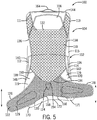
- FIG. 5 is exemplary of this relative movement and is a front elevation view of the backpack 100 of FIG. 2A with the hip belt 122 rotated relative to the frame assembly 102.
- the hip belt 122 is shown having rotated horizontally in a counter-clockwise direction in a generally vertical plane as defined by the frame assembly of the back pack due to the relative forces on backpack 100, such as forces created by the load carried in the sack 160, and on the hip belt 122, such as forces generated by the wearer, causing the resilient panels 118, 120 to stretch and flex.
- the right resilient panel 118 is pulled and stretched as the right arm 126 of the hip belt 122 moves in a downward direction away from the frame assembly 102.
- the left resilient panel 120 may be reduced in size or may experience reduced tension as the left arm 128 moves upwardly towards the frame assembly 102. While the relative movement of the hip belt 122 and the frame assembly 102 is shown in the plane of FIG. 5 , the motion may also be in different planes, such as into or out of the plane of FIG. 5 .
- the benefits of using the resilient panels 118, 120 in securing the hip belt 122 to the frame assembly 102, as disclosed herein, are also obtained when the relative motion is non-vertical, since a vertical load between the two components is supported by the secured attachment between the central portion 124 of the hip belt 122 and the bottom portion of the frame assembly 102, as described above.
- the resilient panels 118, 120 store some of the energy transferred to the hip belt 122 due to the relative movement of the frame assembly 102, reducing the amount of energy transferred to the frame assembly 102, and thus keeping the backpack 100 relatively steady as the wearer moves.
- the suspension panel 110 may provide additional freedom of motion to the resilient panels 118, 120 and hip belt 122.
- the attachment between the resilient panels 118, 120 and the suspension panel 110, and between the hip belt 122 and the suspension panel 110, allows the resilient panels 118, 120 and hip belt 122 to be spaced apart from the support panel 116 and the back panel 108. These attachments may allow for greater rotational movement.
- the suspension panel 110 provides added comfort and ventilation.
- the fixed attachment of the hip belt 122 to the lower portion of the backpack 100 provides vertical load support in order to apply the weight carried in the sack 160 to the wearer's hips.
- the attachment to the bottom panel 130 along the entire lower edge portion 156 of the central portion 124 of the hip belt 122 reduces or minimizes forces applied to the resilient panels 118, 120. Instead, some of the generally vertical load bearing force is transferred to the hip belt 122 through the attached bottom panel 130, or load-bearing panel.
- the combination of the resilient attachment of the upper portion of the hip belt 122 to the frame assembly 102 and the more rigid attachment of the lower portion of the hip belt 122 to the bottom panel 130 allows the hip belt 122 to rotate and/or twist with a wearer's body movements relative to the backpack 100 while the vertical load of the pack is largely supported vertically through the hip belt 122.
- This configuration of the hip belt 122 with the backpack 100 provides vertical stability while allowing for horizontal, and more generally non-vertical, flex capability.
- the motion of rotating may include at least a motion of translating and or pivoting in a curving manner about at least one point, and, for instance, may include at least partially moving in a vertical plane (for example, the plane of the frame assembly 102 shown in FIG. 1 ).
- the motion of twisting may include at least a motion of pivoting and/or translating in a curving motion about at least one axis, and, for instance, may include at least a motion similar to wringing out the water from a wet cloth or towel.
- the relative movement of the hip belt and the frame assembly may be at least a pivoting motion (e.g. such as movement about a point or points in a curved path), which in one example would be substantially in the plane of the frame assembly.
- a flexible hip belt assembly 302 may be separate from a frame assembly 350 for a backpack 300.
- the features in the present embodiment have the same or similar structure and function as described above.
- the flexible hip belt assembly 302 includes a hip belt 304 and two resilient panels 314, 316 attached at opposite lateral sides of the hip belt 304.
- the flexible hip belt assembly 302 may have four attachment locations.
- the resilient panels 314, 316 may each attach to the frame assembly 350 at an upper portion and lower portion of each resilient panel 314, 316.
- the frame assembly 350 includes a back panel 324, a frame member 344, and a support panel 334.
- the resilient panels 314, 316 may attach directly to the back panel 324, to the frame member 344, or to both. As shown, the resilient panels 314, 316 may attach at discrete points. A point on the top edge portion 320 of each resilient panel 314, 316 may attach to a point on the lower middle portion of the frame assembly 350, and a point on the bottom edge portion 319 of each resilient panel 314, 316 may attach to a point on the bottom portion of the frame assembly 350. It is also contemplated that the resilient panels 314, 316 may attach to the frame assembly 350 along a continuous edge portion, or along at least a portion of an edge portion, of each resilient panel 314, 316. In this embodiment, the upper edge portion 310 of the hip belt 304 may attach directly to the back panel 324. As another example of the present embodiment, at least a portion of a bottom edge portion 312 of the flexible hip belt assembly 302 may be fixedly attached to the frame assembly 350 to create an anchor for load bearing support.
- the resilient panels 118, 120, 314, 316 may be integrated with the frame assembly 102, 350, allowing for a resilient attachment point for hip belts of various shapes and sizes.
- the resilient panels 118, 120 may be in various configurations.
- the resilient panels 118, 120 may be positioned along at least a portion of the upper edge portion 154 of the hip belt 122.
- a single resilient panel may extend behind the hip belt 122 to both side edge portions 140, 142 of the frame assembly 102.
- the back panel assembly 104 may include only the back panel 108.
- the resilient panels 118, 120 may attach directly to the back panel 108 instead of to the suspension panel 110 as depicted in the FIGS. 1-3 and 5 .
- the backpack 100, 300 may be formed from a variety of materials and means.
- the frame assembly 102, 350 may be formed from a thermoplastic material (self-reinforced or fiber reinforced), ABS, polycarbonate, polypropylene, polystyrene, PVC, polyamide, and/or PTFE, among others.
- portions of the backpack 100, 300 may be extruded from aluminum or other similar metal.
- the frame assembly 102, 350 may be formed from fiber reinforced epoxy, resin, or other similar material.
- the backpack 100, 300 may be formed or molded in any suitable manner, such as by plug molding, blow molding, injection molding, extrusion, casting, or the like.
- the various components detailed above may be attached by various means, such as, for example, by stitching or sewing, or other mechanical fastening means; or by adhesive, bonding, sonic welding, heat taping, and other non-mechanical mechanisms to secure items together.
- the backpack 100, 300 may be formed from soft side material and/or hard side material. Exemplary materials are noted above.
Landscapes
- Purses, Travelling Bags, Baskets, Or Suitcases (AREA)
- Portable Outdoor Equipment (AREA)
Description
- This application claims the benefit of priority pursuant to 35 U.S.C. §119(e) of
U.S. Provisional Application No. 62/671,961, filed 15 May 2018 - The technology described herein relates generally to backpacks and, more specifically, to hip belt assemblies for backpacks.
- Backpacks have long been used to carry heavy, bulky loads. Various configurations of backpacks exist, including packs having external frames, internal frames, and those without frames. Regardless of the type of backpack, backpacks often include a hip belt attached to a lower portion of the sack to facilitate in distributing the weight of the load onto a wearer in a desirable manner. A hip belt transfers some of the load onto the hips and lumbar area of a wearer, and can reduce the load applied to the user's shoulders, thus allowing the wearer to carry a heavy load in relative comfort.
- Typically, a hip belt is attached to a lower portion of the backpack, extending about the hips of the wearer. Many hip belts include padding to add comfort on the wearer's hip and back, and buckles in the front to secure the hip belt around the wearer's waist. Many hip belts are rigidly attached to the backpack causing the weight of the backpack to shift as a wearer moves. A shifting load may cause overloading to concentrated areas on the wearer, and cause discomfort.
- More recently, certain hip belts have been configured with mechanical adjustments to facilitate the relative movement between the sack and the hip belt. However, many of these mechanical adjustments do not allow the hip belt to move sufficiently relative to the sack of the backpack given the wearer's movements. Thus, as the wearer moves, the load still tends to shift an undesirable amount relative to the wearer's hips. Further, such mechanical attachments of the hip belt may be bulky, complex, and difficult to manufacture.
- It is therefore desirable to provide an improved hip belt assembly, and, more specifically, to provide a simple and resilient hip belt assembly that can conform to a wearer's movements while providing effective load distribution.
- Documents that may be related to the present disclosure include
AT180637 T AU2705797 A AU3900397 A AU3507597 A AU1969883 A AU765141 B2 CA1044197 A ,CA2861974 A1 ,CA2262641 A1 ,CA2258870 A1 ,CN106535705 A ,CN1225559 A ,DE10025154 A1 ,DE873065T1 ,DE29723060 U1 ,DE19781908 T1 ,DE104538T1 ,DE3375366 D1 ,DE69700254 D1 ,DE69700254 T2 ,EP3136903 A1 ,EP0873065 A1 ,EP0873065 B1 ,EP0104538 B1 ,EP0923325 A1 ,EP0628265 A1 ,GB2525662 A GB2350286 B IES71158 B2 IL105983 A JPH078319 A JP2000513255 A MX2014008789 A NZ335931 A NZ201751 A US6015076 A ,US6024265 A ,US5090604 A ,US4015759 A ,US5429287 A ,US5954250 A ,US4504002 A ,US5904282 A ,US5449102 A ,US5954253 A ,US4099657 A ,US4114788 A ,US4154381 A ,US4189076 A ,US5742988 A ,US4479595 A ,US5564612 A ,US5114059 A ,US6276584 B1 ,US6179188 B1 ,US8360289 B2 ,US8066164 B2 ,US6840419 B2 ,US6886727 B2 ,US6607108 B2 ,US20140027481 A1 ,US20170325572 A1 ,US20170049218 A1 ,US20130240590 A1 ,US20060163305 A1 ,US20050092802 A1 ,WO2013109872 A1 ,WO9806298 A1 WO2015166224 A1 ,WO9749312 A1 WO9742851 A1 US4982884 describes a known backpack assembly. - The present disclosure provides a backpack with a flexible hip belt assembly, as described below and defined in the accompanying claims. The backpack includes a frame assembly which may support the structure of the backpack, including a sack for holding articles; a hip belt which may be coupled to the backpack for distributing the weight of a load to a wearer, and one or more resilient panels resiliently coupling the hip belt to the frame assembly. The frame assembly may include a back panel assembly that interfaces with a wearer, a frame member coupled to the back panel assembly, and a support panel operably coupled to the frame member. The back panel assembly may include a back panel dividing the front and back of the backpack, and a suspension panel that is spaced away from the back panel.
- According to the invention, there is provided:
- A backpack (100) comprising: a frame assembly (102); a hip belt (122) including a central portion (124), the central portion (124) having opposing first and second arms (126, 128) extending outwardly from opposing right and left lateral portions (185, 184) of the central portion, the central portion having opposing lateral portions; at least one resilient panel (118, 120) coupling the hip belt (122) to the frame assembly (102), wherein the at least one resilient panel (118, 120) defines opposing upper and lower edge portions (154, 156), and opposing interior and exterior side edge portions (148, 146); and said at least one resilient panel (118, 120) expands or contracts as the hip belt (122) and frame assembly (102) move relative to one another to reduce forces applied to the hip belt (122) by non-vertical movement of the frame assembly (102), wherein a bottom edge portion of the hip belt (122) couples to the frame assembly (102) forming a load bearing seam to support a substantially vertical load applied between the frame assembly (102) and the hip belt (122). The frame assembly may include a back panel assembly defining opposing first and second side edge portions. The frame assembly may also include a frame member disposed about a perimeter of the back panel assembly. The at least part of at least one of the upper edge portion and exterior side edge portion of the at least one resilient panel may be attached to at least one of the back panel assembly and the frame member.
- The back panel assembly may include a back panel defining opposing first and second side edge portions. The back panel assembly may also include a suspension panel coupled to at least an upper portion of the back panel and spaced apart from the back panel. The suspension panel may include a bottom edge portion. The at least part of at least one of the upper edge portion and exterior side edge portion of the at least one resilient member may be attached to at least one of the back panel and the suspension panel.
- An entire length of the exterior side edge portion of the at least one resilient member may be attached to at least one of the back panel assembly and the frame member. An entire length of the top edge portion of the at least one resilient member may be attached to at least a portion of the bottom edge portion of the suspension panel.
- At least a portion of the interior side edge portion of the at least one resilient member may be extended along and coupled to at least a portion of a height of an adjacent lateral edge portion of the central portion of the load support assembly. The interior side edge portion, in one example, may extend along and be coupled to the entirety of the height of the central portion of the load support assembly.
- A bottom edge portion of the load support assembly may couple to the frame assembly forming a load bearing seam.
- A bottom portion of the at least one resilient member may be coupled to an anchor. The anchor may limit rotation and flex at the bottom portion of the resilient panel.
- When force is applied to the load support assembly, the at least one resilient member may stretch in a direction of the applied force. When the applied force is removed, the at least one resilient member may substantially return to an original position.
- The at least one resilient member may form an elongated panel adjacent to the load support assembly. The at least one resilient member may include two laterally spaced resilient panels positioned on opposite sides of the central portion of the load support assembly. The at least one resilient member may include at least two elastic fabric panels. The at least one resilient member may include at least one strap.
- Other examples or embodiments not of the invention may include a backpack having a frame assembly, a load support member including a central portion, and at least one resilient member coupling the frame assembly to the load support member. The at least one resilient member may have a length and a width and may form a flat and elongated shape. The at least one resilient member may stretch along the length and the width. The at least one resilient member may also include two laterally spaced resilient members positioned on opposite sides of the central portion of the load support member. The at least one resilient member may also transition between a first state and a second state as the load support member and frame assembly move relative to one another to reduce the forces applied to the load support member by the non-vertical movement of the frame assembly.
- Additional examples or embodiments not according to the invention may include a backpack having a load supporting belt having a top edge and at least one side edge, and a suspension panel having a bottom portion. The backpack may also include at least one resilient member with a first edge and a second edge. Each edge may define a length. The at least one resilient member may couple to at least one of the top edge and the at least one side edge of the load supporting belt along at least a portion of the length of the first edge. The at least one resilient member may also couple to the bottom portion of the suspension panel along at least a portion of the length of the second edge.
- The load supporting belt may have a bottom edge, and the backpack may include a frame assembly, wherein the bottom edge of the load supporting belt is coupled to a bottom portion of the frame assembly forming a load bearing engagement.
- Additional examples or embodiments of the present disclosure may include a resilient hip belt for a backpack. The hip belt may include two arms extending from a central portion. The central portion may have opposing lateral portions. Two laterally spaced resilient members may be positioned on opposite sides of the central portion of the hip belt. When a force is applied to the hip belt, the resilient members stretch in a direction of the applied force. When the applied force is removed, the resilient members substantially return to an original position.
- Additional examples or embodiments not according to the invention may include a backpack. The backpack may include a frame assembly. The backpack may include a hip belt. The hip belt may include a central portion. The central portion may have opposing first and second arms extending from the central portion and opposing lateral portions. At least one resilient panel may couple the hip belt to the frame assembly. The at least one resilient panel may define opposing upper and lower edge portions, and opposing interior and exterior side edge portions. The at least one resilient panel may expand or contract as the hip belt and frame assembly move relative to one another to reduce forces applied to the hip belt by non-vertical movement of the frame assembly.
- The at least one resilient panel may form an elongated panel coupling the hip belt to the frame assembly. The at least one resilient panel may include two laterally spaced resilient panels each coupled between the frame assembly and the central portion of the hip belt.
- The relative movement of the hip belt and the frame assembly may be at least one of a rotational motion and a twisting motion. The relative movement of the hip belt and the frame assembly may be at least a pivoting motion (e.g. such as movement about a point or points in a curved path).
- At least a part of the interior side edge portion of the at least one resilient panel may be attached to the hip belt and at least part of at least one of the upper edge portion and exterior side edge portion may be attached to the frame assembly.
- The frame assembly may include a back panel assembly. The back panel assembly may define opposing first and second side edge portions. The frame assembly may include a frame member disposed about a perimeter of the back panel assembly. The at least part of at least one of the upper edge portion and exterior side edge portion of the at least one resilient panel may be attached to at least one of the back panel assembly and the frame member.
- The back panel assembly may include a back panel. The back panel may define opposing first and second side edge portions. The at least part of at least one of the upper edge portion and exterior side edge portion of the at least one resilient panel may be attached to the back panel.
- The back panel assembly may include a suspension panel coupled to at least an upper portion of the back panel and spaced apart from the back panel. The suspension panel may include a bottom edge portion. The at least part of at least one of the upper edge portion and exterior side edge portion of the at least one resilient panel may be attached to at least one of the back panel and the suspension panel.
- An entire length of the exterior side edge portion of the at least one resilient panel may be attached to at least one of the back panel assembly and the frame member.
- An entire length of the upper edge portion of the at least one resilient panel may be attached to at least a portion of the bottom edge portion of the suspension panel.
- At least a portion of the interior side edge portion of the at least one resilient panel may extend along and be coupled to at least a portion of a height of an adjacent lateral portion of the central portion of the hip belt. The interior side edge portion may extend along and be coupled to the entirety of a height of the adjacent lateral portion of the central portion of the hip belt.
- When force is applied to the hip belt, the at least one resilient panel may stretch in a direction of the applied force, and when the applied force is removed, the at least one resilient panel may substantially return to an original position.
- Additional examples or embodiments not according to the invention may include a backpack. The backpack may include a frame assembly. The backpack may include a hip belt including a central portion. The backpack may include at least one resilient member coupling the frame assembly to the hip belt. The at least one resilient member may have a length and a width and may define a flat and elongated shape. The at least one resilient member may be stretchable along the length and the width.
- The at least one resilient member may include two laterally spaced resilient members positioned on opposite sides of the central portion of the hip belt. Additionally or separately, the at least one resilient member may include at least one strap.
- The at least one resilient member may transition between a first state and a second state as the hip belt and the frame assembly move relative to one another to reduce the forces applied to the hip belt by non-vertical movement of the frame assembly.
- Additional examples or embodiments not according to the invention may include a backpack. The backpack may include a hip belt having a top edge portion and at least one side edge portion. The backpack may include a suspension panel having a bottom portion. The backpack may include at least one resilient member with a first edge portion and a second edge portion. Each edge portion may define a length. The at least one resilient member may couple to at least one of the top edge portion and the at least one side edge portion of the hip belt along at least a portion of the length of the first edge portion. The at least one resilient member may couple to the bottom portion of the suspension panel along at least a portion of the length of the second edge portion.
- The hip belt may have a bottom edge portion. The backpack may further include a frame assembly. The bottom edge portion of the hip belt may be coupled to a bottom portion of the frame assembly forming a load bearing engagement to support a substantially vertical load applied between the frame assembly and the hip belt.
- Additional embodiments and features are set forth in part in the description that follows, and will become apparent to those skilled in the art upon examination of the specification or may be learned by the practice of the disclosed subject matter. A further understanding of the nature and advantages of the present disclosure may be realized by reference to the remaining portions of the specification and the drawings, which forms a part of this disclosure. One of skill in the art will understand that each of the various aspects and features of the disclosure may advantageously be used separately in some instances, or in combination with other aspects and features of the disclosure in other instances.
- The description will be more fully understood with reference to the following figures in which components are not drawn to scale, which are presented as various examples of the present disclosure and should not be construed as a complete recitation of the scope of the disclosure, characterized in that:
-
FIG. 1 is a front right perspective view of a backpack in accordance with one example, depicting a hip belt with a resilient attachment. -
FIG. 2A is a front elevation view of the backpack ofFIG. 1 with the shoulder straps removed. -
FIG. 2B is a top plan view of the backpack ofFIG. 2A in a schematic cross-section, showing the arrangement of the backpack features behind the hip belt. -
FIG. 3 is a perspective partially exploded view of the backpack ofFIG. 2A , showing the back panel, suspension panel, resilient panels, and hip belt. -
FIG. 4 is a perspective partially exploded view of a backpack frame assembly with a flexible hip belt assembly showing another example of attachment locations therebetween. -
FIG. 5 is a front elevation view of the backpack ofFIG. 2A with the hip belt rotated relative to the frame panel assembly. -
FIG. 6 is an isolated isometric view of the resilient panel engaging the left side of the hip belt for the backpack ofFIG. 1 . -
FIG. 7 is an isolated isometric view of the left side of the hip belt attached to the frame assembly by the resilient panel for the backpack ofFIG. 1 . -
FIG. 8 is a bottom plan view of the backpack ofFIG. 1 , showing the bottom panel and the hip belt. - This disclosure is related to a backpack with a flexible hip belt assembly. Depending on the embodiment, the backpack may include a cargo bag or sack, a frame assembly, a resilient panel, and a hip belt. The frame assembly may include a frame member, a back panel assembly, and a support panel. The back panel assembly may include several panels or layers, including a back panel and a suspension panel. In one embodiment, the hip belt is resiliently coupled to the frame assembly by the resilient panel. The resilient panel expands and contracts as the hip belt and frame assembly move relative to one another to reduce the forces applied to the hip belt by the non-vertical movement of the frame assembly.
- In operation, the resilient panel at least in part couples the hip belt to the frame assembly to generally isolate the movement of the hip belt from the movement of the frame assembly. Since the hip belt engages a wearer's hip region, the hip belt moves with the wearer's hips. The frame assembly supports the cargo bag, which may include a cargo load of up to 50 or more pounds. The frame assembly then includes a load that creates a moment force generally about the attachment between the hip belt and the frame assembly. This cargo load moves, such as swaying, and has an associated momentum that can be transmitted through a traditional connection structure between a frame assembly and a hip belt, and then to the wearer, which can create undesirable effects. The connection structure between the hip belt and the frame assembly disclosed here, and, in particular, the resilient panels as used in this structure, allows the hip belt and frame assembly to move relative to each other to at least partially de-link the movement of the cargo load from the motion of the hip belt. This result is referred to herein as "hip belt flexibility." This de-linking reduces the undesirable forces applied by the moving cargo load to a wearer through the hip belt. This provides advantages over traditional systems, such as, in one example, reduced energy consumption and increased comfort for a wearer. In addition, the resilient panel provides a simplified approach to improving hip belt flexibility that has functional and commercial advantages over the more complex existing systems.
- Turning now to the figures, a
backpack 100 with a flexible hip belt assembly of the present disclosure is shown inFIG. 1. FIG. 1 is a perspective view of abackpack 100 in accordance with one embodiment, depicting ahip belt 122 with a resilient attachment to aframe assembly 102.FIG. 2A is a front elevation view of thebackpack 100 ofFIG. 1 with theshoulder straps 162 removed.FIG. 3 is a perspective partially exploded view of thebackpack 100 ofFIG. 2A , showing theback panel 108,suspension panel 110,resilient panels hip belt 122. As shown inFIGS. 1-3 , thebackpack 100 may include aframe assembly 102, ahip belt 122, one or moreresilient panels bottom panel 130, one ormore cover panels sack 160,shoulder straps 162, one ormore handles 164, buckles 166, adjustment straps 168, and the like. - The
sack 160 is supported on theframe assembly 102, which may include aback panel assembly 104, aframe member 106, and asupport panel 116. Theback panel assembly 104 is positioned on the back side of thebackpack 100, i.e. the side that faces a wearer's back. Theback panel assembly 104 may be made up of one or more panels or layers. For example, theback panel assembly 104 may include one or more of aback panel 108, afoam layer 115, and asuspension panel 110. Theback panel 108 is the panel closest to the front side of thebackpack 100 in theback panel assembly 104. Theback panel 108 may be of any shape that is compatible to engage with a wearer's back and support a sack for carrying cargo. For example, theback panel 108 may be an oval shape, a rectangular shape, or the like, and may be curved or flat. In this example, and as shown inFIG. 2A , theback panel 108 is a generally flat rectangular shape with atop edge portion 144, abottom edge portion 174, and opposing first and secondside edge portions back panel 108 may be made of a variety of materials, such as man-made (e.g. nylon), natural materials (e.g. cotton, leather) or a combination. - As shown in
FIGS. 1-3 , theback panel assembly 104 may also include a suspension orfloat panel 110. Thesuspension panel 110 defines a central body defining a peripheral edge. At least a portion or a plurality of portions of the peripheral edge are secured to theedge portions back panel 108, and the central body is spaced away from theback panel 108. Thesuspension panel 110 is configured to contact a wearer's back. Thesuspension panel 110 may be any shape configured to run along at least a portion of the length of the wearer's back, and the shape of thesuspension panel 110 may vary with the shape of thebackpack 100 and theback panel 108 in particular. Thesuspension panel 110 is smaller than theback panel 108, and, in this example, does not extend beyond the top, bottom and opposingside edge portions back panel 108. Thesuspension panel 110 shown in the figures has a firstside edge portion 136, a secondside edge portion 138, atop edge portion 132 in a concave curved shape and abottom edge portion 134 having a convex curved shape. Thetop edge portion 132 and the firstside edge portion 136 intersect to form a first upperextended portion 111, and thetop edge portion 132 and the secondside edge portion 138 intersect to form a second upperextended portion 113. Thesuspension panel 110 may be a non-extensible material, such as open mesh, foam padding, molded foam panel, spacer mesh, nylon woven fabric, polyester woven fabric, or the like. For example, thesuspension panel 110 may be made up of one or more layers of netting, or may be a solid sheet. The shape of the edges of thesuspension panel 110 may be other than the curves as described above. - The
frame member 106 may be included in theframe assembly 102 to provide structural strength and rigidity to theback panel assembly 104. Theframe member 106 may have a generally rectangular shape, and be positioned, as in this example, generally around the periphery of theback panel 108. Theframe member 106, in this instance, provides the structural support for tensioning thesuspension panel 110 so that it is taught, and spaced away from theback panel 108. The frame member may include one or more of a top support (not shown), a bottom support (not shown), afirst side support 112 and asecond side support 114. Theframe member 106 may be any one of numerous frame structures, such as, for example, an external or internal frame. Theframe member 106 may be made of plastic, metal wire, metal rods, or any other similar materials. It is also contemplated that thebackpack 100 may be frameless. As shown inFIGS. 1 and2A , theframe member 106 is made of a bent-metal rod. - The
support panel 116, shown inFIG. 3 , is coupled to and extends laterally between lower portions of the opposing first and second side supports 112, 114 of theframe member 106. Thesupport panel 116 is under tension and biases the lower portions of theside support members support panel 116 may be a generally rectangular or trapezoidal shape with atop edge portion 180, abottom edge portion 182, and opposing first and secondside edge portions support panel 116 may be any strong, generally inextensible material, such as, for example, a monofilament mesh, nylon, polyester, webbing, foam, non-woven fabric, or the like. Thesupport panel 116, as noted below, is positioned behind the hip belt assembly, and helps support the hip belt assembly away from theback panel 108. - As shown in
FIG. 1 , thehip belt 122, load supporting belt, or load support assembly or member, is coupled to a lower portion of theframe assembly 102, and may extend outwardly from thebackpack 100 in a U- or C-shape, such that it can be secured around and conform to a wearer's hip region. Thehip belt 122 includes acentral portion 124, with opposing right and left wings orarms lateral portions central portion 124. The right and leftlateral portions edge portions lateral portions central portion 124 may be defined by a location where thearms frame assembly 102 to wrap around a user's waist. Thecentral portion 124 is generally positioned in a central region relative to the lateral width of theframe assembly 102. The height dimension of thecentral portion 124 may be greater than the height dimension of thearms arms buckle 166. Thearms hip belt 122 defines anupper edge portion 154 and alower edge portion 156, both of which in this example extend along both thecentral portion 124 and thearms hip belt 122 also has afront surface 129, which is the surface that contacts the wearer, and arear surface 127 facing thesupport panel 116 andback panel 108. - The
hip belt 122 is attached to theframe assembly 102 at a variety of locations to provide both vertical support for the cargo load, as well as the relatively independent rotational movement discussed above. The vertical support for the cargo load is provided by a fixed connection between thelower edge portion 156 of thehip belt 122 and the bottom portion of theframe assembly 102. A resilient attachment is provided by connecting a right and leftresilient panel lateral portions central portion 124 and to theframe assembly 102, which is described in more detail below. As referred to herein, "vertical direction" means generally along a direction of the long length of the frame assembly (for example along aside edge portion 140, 142), "horizontally" or "lateral direction" means generally orthogonal to the direction of the long length of the frame assembly, and "non-vertical" means generally along a direction that includes a lateral component. - The
hip belt 122 may be made of several layers. For example, thehip belt 122 may include at least one of a nylon layer for support, a foam layer for comfort, and a mesh layer for ventilation. In other embodiments, various other materials having sufficient structural strength and flexibility can be used, e.g., composites, e.g., glass-fiber composites; and plastics, e.g., thermoplastics and/or thermosets singly or in combination. It is also contemplated that thehip belt 122 is any existing belt used to support a load for one's back. For example, thehip belt 122 may be two straps that fasten together or it may be a padded structure with pockets. - The resilient attachment may include a plurality of
resilient panels hip belt 122 to theframe assembly 102. As shown in the embodiment inFIGS. 1-3 , the resilient attachment is a plurality ofresilient panels lateral portion central portion 124 of thehip belt 122 and theback panel assembly 104. Alternatively, eachresilient panel lateral portions back panel 108 orframe assembly 102. In an alternate embodiment, the resilient attachment may be at least one resilient strap that has a more discrete connection location than the resilient panels depicted. The resilient strap may include a strap with two ends, or a strap with two or more ends such as, for example, a Y shape, with one end connected to the hip belt and one of the remaining ends attached to at least one of the back panel assembly and the frame member. - As shown in
FIG. 3 , theresilient panels side edge portion 146, an interiorside edge portion 148, atop edge portion 150, abottom edge portion 152, afront surface 119, and a back surface (not shown). The exteriorside edge portion 146 is the edge portion closest to theside edge portion back panel 108 and the interiorside edge portion 148 is the edge portion closest to thehip belt 122. Theedge portions resilient panels front surface 119 is the surface that faces outward toward a wearer, while the back surface is the surface that faces inward toward theback panel 108 and sack 160. In the depicted embodiment, thetop edge portion 150 is at an angle; however, it is contemplated that thetop edge portion 150 may be a straight edge, or have another shape, depending upon the corresponding shape of thesuspension panel 110. As used herein, an "edge" or "edge portion" may or may not be denoted by such a structural feature. For instance, an edge or edge portion may be a portion adjacent to and near the actual free-end of a structural component, such as, for example, theresilient panels backpack 100. For example, an edge or edge portion of theresilient panels resilient panels - The
resilient panels resilient panels resilient panels resilient panels - The
bottom panel 130, or load bearing panel, as shown inFIGS. 2A and8 , may be positioned on the bottom portion of thebackpack 100, connected between thehip belt 122 and theframe assembly 102. Thebottom panel 130 acts as a load bearing component to transfer the vertical load fromsack 160 to thehip belt 122. Thebottom panel 130 has opposing front andback edge portions backpack 100, and generally underneath thecentral portion 124 of thehip belt 122. Thefront edge portion 172 may be fixedly connected to theframe assembly 102, and theback edge portion 194 may be fixedly connected to a bottom portion of thecentral portion 124 of thehip belt 122. Thebottom panel 130 may be any strong material to support a load, such as, for example, nylon, polyester, webbing, static mesh, non-woven fabric, or the like. - As shown in
FIGS. 2A ,7 , and8 , thebackpack 100 may include one or more cover panels, such as aright cover panel 170 and aleft cover panel 171, each positioned on an outer edge portion of the lower portion of the backpack. Eachcover panel resilient panels hip belt 122 andframe assembly 102. In the embodiment depicted inFIGS. 2A and8 , thebackpack 100 has twocover panels frame assembly 102 and on either side of thehip belt 122. Thecover panels resilient panels resilient panels cover panel side edge portion 186, an outerside edge portion 188, atop edge portion 190, and abottom edge portion 192. Thecover panels cover panels bottom panel 130. - With reference to
FIGS. 1-3 and5-8 , the coupling and/or assembly structure of the components described above will be discussed in more detail.FIG. 2B provides a schematic cross-sectional view of the various layers and components of thebackpack 100 ofFIG. 2A , taken alongline 2B-2B. As shown in the figure, thehip belt 122 is spaced away, in this configuration, from thesupport panel 116, theframe member 106, and theback panel 108. Thehip belt 122 is attached to the opposingside edge portions frame assembly 102 by theresilient panels FIG. 2B , theresilient panels hip belt 122 to theback panel 108, and more specifically attach an upper part of thecentral portion 124 of thehip belt 122 to theback panel 108. Thesupport panel 116 is attached to theframe member 106, specifically to the first and second side supports 112, 114, in a tensioned engagement and is positioned behind thehip belt 122 to provide additional support for a wearer's lower back and hips. - With reference to
FIG. 1 and2A , theback panel 108,frame member 106,support panel 116, andsuspension panel 110 may be operably attached to form theframe assembly 102. As shown, theframe member 106 may include a bent-metal rod. The bent-metal rod may be positioned around the perimeter of theback panel 108 and held in place through tension forces. In an alternate embodiment, the bent-metal rod may be enclosed by material that attaches to theback panel 108. The material may partially or entirely enclose the bent-metal rod. Theframe member 106 may be made of other materials such as wire, pulltrusions connected together with corner pieces, or other like structures. - As shown in
FIG. 3 , thesupport panel 116 may attach, in a tensioned engagement, to a lower portion of theframe member 106 near the first and secondside edge portions back panel 108; however, it is also contemplated that thesupport panel 116 attaches to the first and secondside edge portions back panel 108 as well or in isolation. The firstside edge portion 176 of thesupport panel 116 couples to thefirst side support 112, and the secondside edge portion 178 of thesupport panel 116 couples to thesecond side support 114 in a manner that places thesupport panel 116 in a taut engagement with theframe member 106. - The
suspension panel 110 may be attached to at least an upper portion of thebackpack 100. As shown, the first upperextended portion 111 of thesuspension panel 110 is coupled to the firstside edge portion 140 and thetop edge portion 144 of theback panel 108 and may also be attached to theframe member 106. The second upperextended portion 113 of thesuspension panel 110 is coupled to the secondside edge portion 142 and thetop edge portion 144 of theback panel 108 and may also be attached to theframe member 106. Alternatively, thesuspension panel 110 may only attach to theframe member 106. In another embodiment, thesuspension panel 110 or the upperextended portions back panel 108. The attachment of thesuspension panel 110 to thebackpack 100 places thesuspension panel 110 in a suspended position, such that it is spaced away fromback panel 108. In this position, thesuspension panel 110 is taught and inextensible, such that when thesuspension panel 110 is attached to theupper edge portion 154 of thehip belt 122, as discussed in more detail below, the tension runs from the top of theframe assembly 102, through thesuspension panel 110, thehip belt 122, and thebottom panel 130, terminating at the engagement between thebottom panel 130 and theframe assembly 102. - As shown in
FIGS. 1 ,2A ,6, and 7 , thehip belt 122 is attached to theframe assembly 102 by theresilient panels FIG. 7 shows an isolated view of the left side of thehip belt 122 attached to theframe assembly 102 by theresilient panel 120, as shown inFIG. 2B . Theresilient panels frame assembly 102 at one or more locations. In one example, theresilient panels frame assembly 102 at two or four locations of attachment. In the depicted embodiment, tworesilient panels suspension panel 110. At least a portion, a discrete point, or a continuous edge portion of thetop edge portion 150 of eachresilient panel bottom edge portion 134 of thesuspension panel 110. As shown, thetop edge portion 150 of eachresilient panel suspension panel 110 to which it is attached. This allows for the entiretop edge portion 150 of eachresilient panel bottom edge portion 134 of thesuspension panel 110. Each of theresilient panels suspension panel 110 on opposite sides of thecentral portion 124 of thehip belt 122, such that the rightresilient panel 118 is adjacent to the firstside edge portion 140 of theback panel 108 and the leftresilient panel 120 is adjacent to the secondside edge portion 142 of theback panel 108. - The
resilient panels frame assembly 102. As shown inFIG. 7 , the exteriorside edge portion 146 of eachresilient panel side edge portions back panel 108. Theresilient panels frame member 106. Alternatively, theresilient panels frame member 106. As shown in the depicted embodiment, and more detailed inFIG. 7 , the attachment of theresilient panels frame assembly 102 extends along a lower portion of theframe assembly 102 to thebottom panel 130. In other examples, theresilient panels bottom panel 130. It is contemplated that the attachment of the exteriorside edge portions 146 of theresilient panels frame assembly 102 may be along the entirety of the exteriorside edge portions 146, along at least a portion of the exteriorside edge portions 146, or at one or more discrete points on the exteriorside edge portions 146. - The
resilient panels hip belt 122, such that thehip belt 122 is resiliently coupled to thebackpack 100. Each of theresilient panels lateral portion hip belt 122.FIG. 6 is a schematic isolated view of the leftresilient panel 120 attached to thehip belt 122 at the leftlateral portion 184 of thecentral portion 124. As shown inFIG. 6 , theresilient panels lateral portion central portion 124 of thehip belt 122. As shown inFIG. 3 , theresilient panels hip belt 122. As shown, theresilient panels side edge portion 148 of eachresilient panel rear surface 127 of thehip belt 122, adjacent thelateral portions central portion 124 of thehip belt 122, and along at least a portion of the height of thehip belt 122. It is contemplated that eachresilient panel hip belt 122, a discontinuous edge portion, or at discrete points. Theresilient panels hip belt 122 andframe assembly 102 by various conventional means, such as, for example, by stitching or sewing, or other mechanical fastening means. Theresilient panels hip belt 122 andframe assembly 102 move relative to one another. - A
cover panel resilient panels FIG. 7 . As shown, theleft cover panel 171 may cover thefront surface 119 of the leftresilient panel 120 between thehip belt 122 and theframe assembly 102, and protect it from abrasion. Thetop edge portion 190 of theleft cover panel 171 may attach to thefront surface 119 of the leftresilient panel 120. Thebottom edge portion 192 of theleft cover panel 171 may attach to thebottom edge portion 152 of the leftresilient panel 120, to a portion of theback edge portion 194 of thebottom panel 130, or to both. In an alternate embodiment, eachresilient panel top edge portion 190 of eachcover panel bottom edge portion 152 of eachresilient panel top edge portion 190 of eachcover panel FIG. 7 , the innerside edge portion 186 of theleft cover panel 171 may attach to a lower portion of therear surface 127 of thehip belt 122, and the outerside edge portion 188 of theleft cover panel 171 may attach to theframe assembly 102, for example, to a lower portion of aside edge portion back panel 108, to a lower portion of theframe member 106, or to both. At least one of thebottom panel 130, thecover panels frame assembly 102 act as an anchor to prevent rotation and flexion at the bottom portion of eachresilient panel - A portion of the
hip belt 122 may also attach directly to a portion of theframe assembly 102. As shown inFIGS. 1 and2A , a top portion of thehip belt 122 may attach to a lower portion of thesuspension panel 110. As shown, and in this example, theupper edge portion 154 of thehip belt 122 attaches to a middle portion of thebottom edge portion 134 of thesuspension panel 110. - The
hip belt 122 is further attached to a lower portion of theframe assembly 102. Thehip belt 122 may attach along a lower load bearing seam of thebackpack 100 to support the load in thesack 160, primarily in a vertical direction. As shown inFIGS. 1 and8 , thehip belt 122 may attach to thebottom panel 130; however, it is contemplated that the lower portion of thehip belt 122 may attach directly to a lower portion of theframe assembly 102. In the depicted embodiment, the entirelower edge portion 156 of thecentral portion 124 of thehip belt 122 attaches to a portion of theback edge portion 194 of thebottom panel 130. As mentioned, this creates an anchor between thehip belt 122 and theframe assembly 102 to create a load bearing support for the weight of the articles carried in thebackpack 100. - As shown in
FIGS. 7 and8 , thebottom panel 130 may be further attached to theresilient panels panels frame assembly 102. In the depicted embodiment, a portion of theback edge portion 194 of thebottom panel 130 attaches to one or both of thebottom edge portions 152 of theresilient panels bottom edge portions 192 of thecover panels bottom edge portions 152 of theresilient panels bottom edge portions 192 of thecover panels back edge portion 194 of thebottom panel 130. It is contemplated that thebottom panel 130 and coverpanels - The
bottom panel 130 may also attach to theframe assembly 102. For example, thebottom panel 130 may attach to a lower portion of theback panel 108. As shown inFIG. 8 , thefront edge portion 172 of thebottom panel 130 may attach to thebottom edge portion 174 of theback panel 108 forming a seam. Thebottom panel 130 may also be coupled to theframe member 106. For example, theframe member 106 may seat near the seam where thebottom panel 130 andback panel 108 intersect. In this configuration, theframe member 106 may be in tensioned engagement with a portion of thebottom panel 130. - The attachment of the
hip belt 122 to theframe assembly 102 using theresilient panels hip belt 122 to move relative to theframe assembly 102. Theresilient panels hip belt 122 andframe assembly 102 move relative to one another to reduce the forces applied tohip belt 122, and thus to the wearer, by the non-vertical movement of theframe assembly 102. The resilient panels may transition between a first, or initial, position or state and a second position or state. In the first position, the resilient panels may be under some or no tension. In the second position, the resilient panels are under tension, such as, for example, being stretched or rotated or twisted along a length, a width, or somewhere in between, such as, for example, in a diagonal direction. -
FIG. 5 is exemplary of this relative movement and is a front elevation view of thebackpack 100 ofFIG. 2A with thehip belt 122 rotated relative to theframe assembly 102. Thehip belt 122 is shown having rotated horizontally in a counter-clockwise direction in a generally vertical plane as defined by the frame assembly of the back pack due to the relative forces onbackpack 100, such as forces created by the load carried in thesack 160, and on thehip belt 122, such as forces generated by the wearer, causing theresilient panels resilient panel 118 is pulled and stretched as theright arm 126 of thehip belt 122 moves in a downward direction away from theframe assembly 102. The leftresilient panel 120 may be reduced in size or may experience reduced tension as theleft arm 128 moves upwardly towards theframe assembly 102. While the relative movement of thehip belt 122 and theframe assembly 102 is shown in the plane ofFIG. 5 , the motion may also be in different planes, such as into or out of the plane ofFIG. 5 . The benefits of using theresilient panels hip belt 122 to theframe assembly 102, as disclosed herein, are also obtained when the relative motion is non-vertical, since a vertical load between the two components is supported by the secured attachment between thecentral portion 124 of thehip belt 122 and the bottom portion of theframe assembly 102, as described above. Theresilient panels hip belt 122 due to the relative movement of theframe assembly 102, reducing the amount of energy transferred to theframe assembly 102, and thus keeping thebackpack 100 relatively steady as the wearer moves. - The
suspension panel 110 may provide additional freedom of motion to theresilient panels hip belt 122. The attachment between theresilient panels suspension panel 110, and between thehip belt 122 and thesuspension panel 110, allows theresilient panels hip belt 122 to be spaced apart from thesupport panel 116 and theback panel 108. These attachments may allow for greater rotational movement. In addition, thesuspension panel 110 provides added comfort and ventilation. - The fixed attachment of the
hip belt 122 to the lower portion of thebackpack 100 provides vertical load support in order to apply the weight carried in thesack 160 to the wearer's hips. For example, the attachment to thebottom panel 130 along the entirelower edge portion 156 of thecentral portion 124 of thehip belt 122 reduces or minimizes forces applied to theresilient panels hip belt 122 through the attachedbottom panel 130, or load-bearing panel. The combination of the resilient attachment of the upper portion of thehip belt 122 to theframe assembly 102 and the more rigid attachment of the lower portion of thehip belt 122 to thebottom panel 130 allows thehip belt 122 to rotate and/or twist with a wearer's body movements relative to thebackpack 100 while the vertical load of the pack is largely supported vertically through thehip belt 122. This configuration of thehip belt 122 with thebackpack 100 provides vertical stability while allowing for horizontal, and more generally non-vertical, flex capability. The motion of rotating may include at least a motion of translating and or pivoting in a curving manner about at least one point, and, for instance, may include at least partially moving in a vertical plane (for example, the plane of theframe assembly 102 shown inFIG. 1 ). The motion of twisting may include at least a motion of pivoting and/or translating in a curving motion about at least one axis, and, for instance, may include at least a motion similar to wringing out the water from a wet cloth or towel. The relative movement of the hip belt and the frame assembly may be at least a pivoting motion (e.g. such as movement about a point or points in a curved path), which in one example would be substantially in the plane of the frame assembly. - Other embodiments for a backpack with a flexible hip belt are envisioned. As shown in the embodiment depicted in
FIG. 4 , a flexiblehip belt assembly 302 may be separate from aframe assembly 350 for abackpack 300. The features in the present embodiment have the same or similar structure and function as described above. In the present embodiment, the flexiblehip belt assembly 302 includes ahip belt 304 and tworesilient panels hip belt 304. The flexiblehip belt assembly 302 may have four attachment locations. Theresilient panels frame assembly 350 at an upper portion and lower portion of eachresilient panel frame assembly 350 includes aback panel 324, aframe member 344, and asupport panel 334. Theresilient panels back panel 324, to theframe member 344, or to both. As shown, theresilient panels top edge portion 320 of eachresilient panel frame assembly 350, and a point on thebottom edge portion 319 of eachresilient panel frame assembly 350. It is also contemplated that theresilient panels frame assembly 350 along a continuous edge portion, or along at least a portion of an edge portion, of eachresilient panel upper edge portion 310 of thehip belt 304 may attach directly to theback panel 324. As another example of the present embodiment, at least a portion of abottom edge portion 312 of the flexiblehip belt assembly 302 may be fixedly attached to theframe assembly 350 to create an anchor for load bearing support. - In an alternate embodiment pertinent to both of the above examples, the
resilient panels frame assembly - In other embodiments, the
resilient panels resilient panels upper edge portion 154 of thehip belt 122. There may be more than tworesilient panels hip belt 122 to bothside edge portions frame assembly 102. - In additional embodiments, the
back panel assembly 104 may include only theback panel 108. In this configuration, theresilient panels back panel 108 instead of to thesuspension panel 110 as depicted in theFIGS. 1-3 and5 . - The
backpack frame assembly backpack frame assembly backpack backpack - All relative and directional references (including: upper, lower, upward, downward, left, right, leftward, rightward, top, bottom, side, above, below, front, middle, back, vertical, horizontal, and so forth) are given by way of example to aid the reader's understanding of the particular examples described herein. They should not be read to be requirements or limitations, particularly as to the position, orientation, or use unless specifically set forth in the claims. Connection references (e.g., attached, coupled, connected, joined, and the like) are to be construed broadly and may include intermediate members between a connection of elements and relative movement between elements. As such, connection references do not necessarily infer that two elements are directly connected and in fixed relation to each other, unless specifically set forth in the claims.
- Those skilled in the art will appreciate that the presently disclosed examples teach by way of example and not by limitation. Therefore, the matter contained in the above description or shown in the accompanying drawings should be interpreted as illustrative and not in a limiting sense.
Claims (14)
- A backpack (100) comprising:a frame assembly (102);a hip belt (122) including a central portion (124), the central portion (124) having opposing first and second arms (126, 128) extending outwardly from opposing right and left lateral portions (185, 184) of the central portion;at least one resilient panel (118, 120) coupling the hip belt (122) to the frame assembly (102), wherein the at least one resilient panel (118, 120) defines opposing upper and lower edge portions (154, 156), and opposing interior and exterior side edge portions (148, 146); andsaid at least one resilient panel (118, 120) expands or contracts as the hip belt (122) and frame assembly (102) move relative to one another to reduce forces applied to the hip belt (122) by non-vertical movement of the frame assembly (102), wherein a bottom edge portion of the hip belt (122) couples to the frame assembly (102) forming a load bearing seam to support a substantially vertical load applied between the frame assembly (102) and the hip belt (122).
- The backpack (100) of claim 1, wherein the at least one resilient panel (118, 120) forms an elongated panel coupling the hip belt (122) to the frame assembly (102).
- : The backpack (100) of claim 1 or 2, wherein the at least one resilient panel (118, 120) comprises two laterally spaced resilient panels each coupled between the frame assembly (102) and the central portion of the hip belt (122).
- The backpack (100) of any of claims 1 to 3, wherein the relative movement of the hip belt (122) and the frame assembly (102) is at least one of a rotational motion and a twisting motion.
- The backpack (100) of any of claims 1 to 4, wherein at least a part of the interior side edge portion (148) of the at least one resilient panel (118, 120) is attached to the hip belt (122) and at least part of at least one of the upper edge portion (154) and exterior side edge portion (142) is attached to the frame assembly (102).
- The backpack (100) of any of claims 1 to 5, wherein the frame assembly (102) comprises:a back panel assembly (104), wherein the back panel assembly (104) defines opposing first and second side edge portions (140, 142);a frame member (106) disposed about a perimeter of the back panel assembly (104); andwherein the at least part of at least one of the upper edge portion (154) and exterior side edge portion (146) of the at least one resilient panel (118, 120) is attached to at least one of the back panel assembly (104) and the frame member (106).
- The backpack (100) of any of claim 6, wherein the back panel assembly (104) comprises a back panel (108), wherein the back panel (108) defines opposing first and second side edge portions; and
wherein the at least part of at least one of the upper edge portion (154) and exterior side edge portion (146) of the at least one resilient panel (118, 120) is attached to the back panel (108). - The backpack (100) of claim 6 or claim 7, wherein the back panel assembly (104) further comprises a suspension panel (110) coupled to at least an upper portion of the back panel (108) and spaced apart from the back panel (108), wherein the suspension panel (110) includes a bottom edge portion (134), and wherein the at least part of at least one of the upper edge portion (154) and exterior side edge portion (146) of the at least one resilient panel (118, 120) is attached to at least one of the back panel (108) and the suspension panel (110).
- The backpack (100) of claim 6 or any of claims 7 to 8 when dependent on claim 6, wherein an entire length of the exterior side edge portion (146) of the at least one resilient panel (118, 120) is attached to at least one of the back panel assembly (104) and the frame member (106).
- The backpack (100) of claim 8 or claim 9, when dependent on claim 8, wherein an entire length of the upper edge portion (154) of the at least one resilient panel (118, 120) is attached to at least a portion of the bottom edge portion (134) of the suspension panel (110).
- The backpack (100) of any of claims 1 to 10, wherein at least a portion of the interior side edge portion (148) of the at least one resilient panel (118, 120) extends along and is coupled to at least a portion of a height of an adjacent lateral portion (185, 186) of the central portion of the hip belt (122).
- The backpack (100) of claim 11, wherein the interior side edge portion (148) extends along and is coupled to the entirety of a height of the adjacent lateral portion (185, 186) of the central portion of the hip belt (122).
- The backpack (100) of any of claims 1 to 12, wherein
when force is applied to the hip belt (122), the at least one resilient panel (118, 120) stretches in a direction of the applied force, and
when the applied force is removed, the at least one resilient panel (118, 120) substantially returns to an original position. - A backpack (100) according to any preceding claim, wherein:
the at least one resilient panel (118, 120) has a length and a width and defines a flat and elongated shape; and wherein the at least one resilient panel (118, 120) comprises at least one strap.
Applications Claiming Priority (2)
| Application Number | Priority Date | Filing Date | Title |
|---|---|---|---|
| US201862671961P | 2018-05-15 | 2018-05-15 | |
| US15/996,214 US10806238B2 (en) | 2018-05-15 | 2018-06-01 | Backpack with dynamic flexible hip belt |
Publications (2)
| Publication Number | Publication Date |
|---|---|
| EP3569100A1 EP3569100A1 (en) | 2019-11-20 |
| EP3569100B1 true EP3569100B1 (en) | 2021-01-27 |
Family
ID=67437287
Family Applications (1)
| Application Number | Title | Priority Date | Filing Date |
|---|---|---|---|
| EP19174561.1A Active EP3569100B1 (en) | 2018-05-15 | 2019-05-15 | Backpack with dynamic flexible hip belt |
Country Status (2)
| Country | Link |
|---|---|
| US (1) | US10806238B2 (en) |
| EP (1) | EP3569100B1 (en) |
Cited By (1)
| Publication number | Priority date | Publication date | Assignee | Title |
|---|---|---|---|---|
| DE102022131067A1 (en) | 2022-11-23 | 2024-05-23 | Vaude Sport Gmbh & Co. Kg | Back carrying device with carrying frame |
Families Citing this family (4)
| Publication number | Priority date | Publication date | Assignee | Title |
|---|---|---|---|---|
| US11723831B2 (en) * | 2019-04-16 | 2023-08-15 | Li Zhijian | Adjustable massage structure and massage backpack |
| WO2021263200A1 (en) * | 2020-06-25 | 2021-12-30 | Zaib Shafiq | Posture correcting everyday backpack |
| USD958541S1 (en) * | 2020-10-07 | 2022-07-26 | Alex McClure | Set of spacers for a backpack |
| US20230313944A1 (en) * | 2022-04-04 | 2023-10-05 | Jacob Chandler Odom | Apparatus, system, and method for temporarily holding small objects for adjustment or manipulation |
Family Cites Families (46)
| Publication number | Priority date | Publication date | Assignee | Title |
|---|---|---|---|---|
| US4015759A (en) | 1975-05-27 | 1977-04-05 | Dreissigacker Peter D | Backpack frame having shoulder and hip supports with flexible connection to hip support |
| US4099657A (en) | 1976-05-26 | 1978-07-11 | Zufich Anthony C | Backpack and frame apparatus |
| US4189076A (en) | 1976-05-26 | 1980-02-19 | Zufich Anthony C | Backpack and frame apparatus |
| CA1044197A (en) | 1977-01-24 | 1978-12-12 | Peter D. Dreissigacker | Backpack frame having shoulder and hip supports with flexible connection to hip support |
| NZ201751A (en) | 1982-08-30 | 1985-05-31 | Macpac Produucts N Z Ltd | Tramper's pack;flexible connection secures hip belt to pack sac |
| US4479595A (en) | 1982-09-28 | 1984-10-30 | Canadian Mountaineering Equipment Ltd. | Back pack |
| US4676418A (en) * | 1986-03-12 | 1987-06-30 | Lowe Alpine Systems, Inc. | Backpack having improved load distribution and stabilizing structures |
| US4982884A (en) | 1986-03-18 | 1991-01-08 | Wise Stephen A | Backpack carrier assemblies |
| US5429287A (en) | 1990-01-30 | 1995-07-04 | Illinois Tool Works Inc. | Adjustable hip-brace for a backpack |
| US5090604A (en) * | 1990-07-24 | 1992-02-25 | The North Face | Backpack device |
| US5114059A (en) | 1990-11-30 | 1992-05-19 | Ultimate Direction, Inc. | Universally adjustable, frameless backpack |
| IL105983A (en) | 1993-06-10 | 1997-04-15 | Modan Ind 1983 Ltd | Backpack |
| US5503314A (en) * | 1994-06-21 | 1996-04-02 | Fiscus; Wayne R. | Helixical backpack carrier |
| US5564612A (en) * | 1995-01-27 | 1996-10-15 | Bianchi International | Modular backpack |
| IES71158B2 (en) | 1996-05-10 | 1997-01-29 | Lowe Alpine Holdings Limited | A rucksack |
| US5954250A (en) | 1996-05-31 | 1999-09-21 | Draeger Limited | Harnesses |
| US5742988A (en) | 1996-06-26 | 1998-04-28 | Johnson Worldwide Associates, Inc. | Quick-release pin latch assembly |
| US5954253A (en) | 1996-06-26 | 1999-09-21 | Johnson Worldwide Associates, Inc. | Flexible frame load carrying system |
| ATE207715T1 (en) * | 1996-07-30 | 2001-11-15 | Big Pack Gmbh | BACKPACK |
| US5904282A (en) | 1996-08-14 | 1999-05-18 | K-2 Corporation | External frame backpack harness |
| US5762251C1 (en) | 1996-08-14 | 2001-12-11 | Dana Design Ltd | External frame backpack with flexible harness |
| US6015076A (en) | 1997-06-20 | 2000-01-18 | Pennington; Daryl | Bridging hipbelt for a backpack |
| NZ335931A (en) | 1999-05-24 | 2000-11-24 | Macpac Wilderness Equipment Lt | Pack with frame and special strap arrangement |
| US6607108B2 (en) * | 2001-02-13 | 2003-08-19 | Recreational Equipment, Inc. | Load transfer and stabilization system for backpacks |
| US6886727B2 (en) | 2001-04-07 | 2005-05-03 | Talons Adventure Gear, Inc. | Detachable back pack waist belt |
| US6840419B2 (en) | 2002-08-07 | 2005-01-11 | Watermark Paddlesports, Inc. | Adjustable load support-mounting device for a backpack |
| CA2519133C (en) * | 2003-03-14 | 2012-08-28 | The North Face Apparel Corp. | Backpack suspension system |
| NZ527022A (en) * | 2003-07-15 | 2005-02-25 | Macpac Wilderness Equipment Lt | Improved pack and frame for pack |
| US20050092802A1 (en) | 2003-11-03 | 2005-05-05 | Maley Ian J. | Backpack and components therefor |
| NO322177B1 (en) * | 2005-01-13 | 2006-08-21 | Bergans Fritid As | Storage of a hip belt for a backpack |
| US20060163305A1 (en) | 2005-01-27 | 2006-07-27 | Agron, Inc. | Backpack frame |
| US8066164B2 (en) | 2005-06-08 | 2011-11-29 | Gregory Mountain Products, Llc | Backpack having auto-adjusting waistbelt |
| GB0623719D0 (en) * | 2006-11-28 | 2007-01-10 | Draeger Safety Uk Ltd | A harness for use with breathing apparatus |
| US9113697B2 (en) * | 2007-03-20 | 2015-08-25 | Nemo Equipment, Inc. | Ergonomic segmented pack |
| EP2152890A1 (en) * | 2007-05-23 | 2010-02-17 | MannKind Corporation | Multicistronic vectors and methods for their design |
| US9254030B2 (en) * | 2009-03-24 | 2016-02-09 | Black Diamond Equipment, Ltd. | Carrying device dual shoulder strap system |
| US8714424B2 (en) * | 2009-03-24 | 2014-05-06 | Black Diamond Equipment Ltd. | Carrying device waist belt system |
| DE102009042455B4 (en) * | 2009-09-23 | 2016-03-17 | Hexonia Gmbh | Support system with a ballistic protective vest |
| WO2011053961A2 (en) * | 2009-11-02 | 2011-05-05 | C & P Hiam Associates Llc | Stable backpack |
| US8360289B2 (en) | 2010-07-21 | 2013-01-29 | Gregory Mountain Products | Adjustable waist belt system for a carrying apparatus |
| IL210054A0 (en) | 2010-12-16 | 2011-02-28 | Source Vagabond Systems Ltd | Load carrier device |
| MX2014008789A (en) | 2012-01-19 | 2015-03-19 | Emerson Electric Co | Articulated backpack apparatus and system. |
| US20130240590A1 (en) | 2012-03-17 | 2013-09-19 | James Alan Montgomery | Ultralight Backpack |
| US9462875B2 (en) * | 2013-03-11 | 2016-10-11 | The North Face Apparel Corp. | Backpack with adjustable hip-belts |
| GB2525662B (en) | 2014-05-01 | 2020-08-12 | James Moncreiff Robert | Free-flex harness |
| US10004320B2 (en) | 2016-05-10 | 2018-06-26 | Amer Sports Canada Inc. | Hipbelt suspension system for use with a backpack |
-
2018
- 2018-06-01 US US15/996,214 patent/US10806238B2/en active Active
-
2019
- 2019-05-15 EP EP19174561.1A patent/EP3569100B1/en active Active
Non-Patent Citations (1)
| Title |
|---|
| None * |
Cited By (1)
| Publication number | Priority date | Publication date | Assignee | Title |
|---|---|---|---|---|
| DE102022131067A1 (en) | 2022-11-23 | 2024-05-23 | Vaude Sport Gmbh & Co. Kg | Back carrying device with carrying frame |
Also Published As
| Publication number | Publication date |
|---|---|
| US10806238B2 (en) | 2020-10-20 |
| EP3569100A1 (en) | 2019-11-20 |
| US20190350347A1 (en) | 2019-11-21 |
Similar Documents
| Publication | Publication Date | Title |
|---|---|---|
| EP3569100A1 (en) | Backpack with dynamic flexible hip belt | |
| CN102578784B (en) | There is the bag of self-adjusting straps | |
| CA2261672C (en) | Internal frame pack with load-responsive spring rods | |
| US6471105B1 (en) | Shoulder carrier with inflatable lumbar support | |
| US6863202B2 (en) | Shoulder carrier with inflatable lumbar support | |
| US8381956B2 (en) | Backpack frame system | |
| CA2646301C (en) | Backpack frame system | |
| CA2849440C (en) | Body armor support harness | |
| CN108471864B (en) | load bearing system | |
| US9119459B2 (en) | Variable suspension system for backpacks | |
| KR20230080498A (en) | Travel pillow with anchoring features | |
| WO1998006298A1 (en) | External frame backpack with flexible harness | |
| WO2000074517A1 (en) | Backpack having a modular frame | |
| AU3635100A (en) | Improvement in tramper's pack | |
| EP0748599B1 (en) | Improvements in and relating to backpacks | |
| KR102423665B1 (en) | Backpack having fastening unit | |
| CN114259124B (en) | Backpack with load-bearing and corrective functions | |
| US20050279784A1 (en) | Adipo-mimetic motion-control hydration system pack | |
| AU2011100903A4 (en) | Backpack frame system | |
| CA2708383C (en) | Backpack frame system | |
| HK1162270B (en) | Bag with self-adjusting straps | |
| HK1168740B (en) | Self adjusting contoured strap device and method | |
| WO2001045530A1 (en) | Garment for use with backpacks | |
| HK1106112A (en) | A baby carrier | |
| AU2015201222A1 (en) | Backpack frame system |
Legal Events
| Date | Code | Title | Description |
|---|---|---|---|
| PUAI | Public reference made under article 153(3) epc to a published international application that has entered the european phase |
Free format text: ORIGINAL CODE: 0009012 |
|
| STAA | Information on the status of an ep patent application or granted ep patent |
Free format text: STATUS: THE APPLICATION HAS BEEN PUBLISHED |
|
| AK | Designated contracting states |
Kind code of ref document: A1 Designated state(s): AL AT BE BG CH CY CZ DE DK EE ES FI FR GB GR HR HU IE IS IT LI LT LU LV MC MK MT NL NO PL PT RO RS SE SI SK SM TR |
|
| AX | Request for extension of the european patent |
Extension state: BA ME |
|
| STAA | Information on the status of an ep patent application or granted ep patent |
Free format text: STATUS: REQUEST FOR EXAMINATION WAS MADE |
|
| 17P | Request for examination filed |
Effective date: 20200601 |
|
| RBV | Designated contracting states (corrected) |
Designated state(s): AL AT BE BG CH CY CZ DE DK EE ES FI FR GB GR HR HU IE IS IT LI LT LU LV MC MK MT NL NO PL PT RO RS SE SI SK SM TR |
|
| RAP1 | Party data changed (applicant data changed or rights of an application transferred) |
Owner name: SAMSONITE IP HOLDINGS S.A R.L. |
|
| RIC1 | Information provided on ipc code assigned before grant |
Ipc: A45F 3/08 20060101ALI20200703BHEP Ipc: A45F 3/04 20060101AFI20200703BHEP |
|
| GRAP | Despatch of communication of intention to grant a patent |
Free format text: ORIGINAL CODE: EPIDOSNIGR1 |
|
| STAA | Information on the status of an ep patent application or granted ep patent |
Free format text: STATUS: GRANT OF PATENT IS INTENDED |
|
| INTG | Intention to grant announced |
Effective date: 20200817 |
|
| GRAS | Grant fee paid |
Free format text: ORIGINAL CODE: EPIDOSNIGR3 |
|
| GRAA | (expected) grant |
Free format text: ORIGINAL CODE: 0009210 |
|
| STAA | Information on the status of an ep patent application or granted ep patent |
Free format text: STATUS: THE PATENT HAS BEEN GRANTED |
|
| AK | Designated contracting states |
Kind code of ref document: B1 Designated state(s): AL AT BE BG CH CY CZ DE DK EE ES FI FR GB GR HR HU IE IS IT LI LT LU LV MC MK MT NL NO PL PT RO RS SE SI SK SM TR |
|
| REG | Reference to a national code |
Ref country code: GB Ref legal event code: FG4D |
|
| REG | Reference to a national code |
Ref country code: CH Ref legal event code: EP |
|
| REG | Reference to a national code |
Ref country code: AT Ref legal event code: REF Ref document number: 1357567 Country of ref document: AT Kind code of ref document: T Effective date: 20210215 |
|
| REG | Reference to a national code |
Ref country code: IE Ref legal event code: FG4D |
|
| REG | Reference to a national code |
Ref country code: DE Ref legal event code: R096 Ref document number: 602019002330 Country of ref document: DE |
|
| REG | Reference to a national code |
Ref country code: NL Ref legal event code: MP Effective date: 20210127 |
|
| REG | Reference to a national code |
Ref country code: LT Ref legal event code: MG9D |
|
| REG | Reference to a national code |
Ref country code: AT Ref legal event code: MK05 Ref document number: 1357567 Country of ref document: AT Kind code of ref document: T Effective date: 20210127 |
|
| PG25 | Lapsed in a contracting state [announced via postgrant information from national office to epo] |
Ref country code: BG Free format text: LAPSE BECAUSE OF FAILURE TO SUBMIT A TRANSLATION OF THE DESCRIPTION OR TO PAY THE FEE WITHIN THE PRESCRIBED TIME-LIMIT Effective date: 20210427 Ref country code: HR Free format text: LAPSE BECAUSE OF FAILURE TO SUBMIT A TRANSLATION OF THE DESCRIPTION OR TO PAY THE FEE WITHIN THE PRESCRIBED TIME-LIMIT Effective date: 20210127 Ref country code: GR Free format text: LAPSE BECAUSE OF FAILURE TO SUBMIT A TRANSLATION OF THE DESCRIPTION OR TO PAY THE FEE WITHIN THE PRESCRIBED TIME-LIMIT Effective date: 20210428 Ref country code: FI Free format text: LAPSE BECAUSE OF FAILURE TO SUBMIT A TRANSLATION OF THE DESCRIPTION OR TO PAY THE FEE WITHIN THE PRESCRIBED TIME-LIMIT Effective date: 20210127 Ref country code: PT Free format text: LAPSE BECAUSE OF FAILURE TO SUBMIT A TRANSLATION OF THE DESCRIPTION OR TO PAY THE FEE WITHIN THE PRESCRIBED TIME-LIMIT Effective date: 20210527 Ref country code: NO Free format text: LAPSE BECAUSE OF FAILURE TO SUBMIT A TRANSLATION OF THE DESCRIPTION OR TO PAY THE FEE WITHIN THE PRESCRIBED TIME-LIMIT Effective date: 20210427 Ref country code: LT Free format text: LAPSE BECAUSE OF FAILURE TO SUBMIT A TRANSLATION OF THE DESCRIPTION OR TO PAY THE FEE WITHIN THE PRESCRIBED TIME-LIMIT Effective date: 20210127 |
|
| PG25 | Lapsed in a contracting state [announced via postgrant information from national office to epo] |
Ref country code: SE Free format text: LAPSE BECAUSE OF FAILURE TO SUBMIT A TRANSLATION OF THE DESCRIPTION OR TO PAY THE FEE WITHIN THE PRESCRIBED TIME-LIMIT Effective date: 20210127 Ref country code: AT Free format text: LAPSE BECAUSE OF FAILURE TO SUBMIT A TRANSLATION OF THE DESCRIPTION OR TO PAY THE FEE WITHIN THE PRESCRIBED TIME-LIMIT Effective date: 20210127 Ref country code: RS Free format text: LAPSE BECAUSE OF FAILURE TO SUBMIT A TRANSLATION OF THE DESCRIPTION OR TO PAY THE FEE WITHIN THE PRESCRIBED TIME-LIMIT Effective date: 20210127 Ref country code: LV Free format text: LAPSE BECAUSE OF FAILURE TO SUBMIT A TRANSLATION OF THE DESCRIPTION OR TO PAY THE FEE WITHIN THE PRESCRIBED TIME-LIMIT Effective date: 20210127 Ref country code: PL Free format text: LAPSE BECAUSE OF FAILURE TO SUBMIT A TRANSLATION OF THE DESCRIPTION OR TO PAY THE FEE WITHIN THE PRESCRIBED TIME-LIMIT Effective date: 20210127 |
|
| PG25 | Lapsed in a contracting state [announced via postgrant information from national office to epo] |
Ref country code: IS Free format text: LAPSE BECAUSE OF FAILURE TO SUBMIT A TRANSLATION OF THE DESCRIPTION OR TO PAY THE FEE WITHIN THE PRESCRIBED TIME-LIMIT Effective date: 20210527 |
|
| REG | Reference to a national code |
Ref country code: DE Ref legal event code: R097 Ref document number: 602019002330 Country of ref document: DE |
|
| PG25 | Lapsed in a contracting state [announced via postgrant information from national office to epo] |
Ref country code: SM Free format text: LAPSE BECAUSE OF FAILURE TO SUBMIT A TRANSLATION OF THE DESCRIPTION OR TO PAY THE FEE WITHIN THE PRESCRIBED TIME-LIMIT Effective date: 20210127 Ref country code: CZ Free format text: LAPSE BECAUSE OF FAILURE TO SUBMIT A TRANSLATION OF THE DESCRIPTION OR TO PAY THE FEE WITHIN THE PRESCRIBED TIME-LIMIT Effective date: 20210127 Ref country code: EE Free format text: LAPSE BECAUSE OF FAILURE TO SUBMIT A TRANSLATION OF THE DESCRIPTION OR TO PAY THE FEE WITHIN THE PRESCRIBED TIME-LIMIT Effective date: 20210127 |
|
| PG25 | Lapsed in a contracting state [announced via postgrant information from national office to epo] |
Ref country code: DK Free format text: LAPSE BECAUSE OF FAILURE TO SUBMIT A TRANSLATION OF THE DESCRIPTION OR TO PAY THE FEE WITHIN THE PRESCRIBED TIME-LIMIT Effective date: 20210127 Ref country code: SK Free format text: LAPSE BECAUSE OF FAILURE TO SUBMIT A TRANSLATION OF THE DESCRIPTION OR TO PAY THE FEE WITHIN THE PRESCRIBED TIME-LIMIT Effective date: 20210127 Ref country code: RO Free format text: LAPSE BECAUSE OF FAILURE TO SUBMIT A TRANSLATION OF THE DESCRIPTION OR TO PAY THE FEE WITHIN THE PRESCRIBED TIME-LIMIT Effective date: 20210127 |
|
| PLBE | No opposition filed within time limit |
Free format text: ORIGINAL CODE: 0009261 |
|
| STAA | Information on the status of an ep patent application or granted ep patent |
Free format text: STATUS: NO OPPOSITION FILED WITHIN TIME LIMIT |
|
| 26N | No opposition filed |
Effective date: 20211028 |
|
| PG25 | Lapsed in a contracting state [announced via postgrant information from national office to epo] |
Ref country code: MC Free format text: LAPSE BECAUSE OF FAILURE TO SUBMIT A TRANSLATION OF THE DESCRIPTION OR TO PAY THE FEE WITHIN THE PRESCRIBED TIME-LIMIT Effective date: 20210127 Ref country code: LU Free format text: LAPSE BECAUSE OF NON-PAYMENT OF DUE FEES Effective date: 20210515 Ref country code: AL Free format text: LAPSE BECAUSE OF FAILURE TO SUBMIT A TRANSLATION OF THE DESCRIPTION OR TO PAY THE FEE WITHIN THE PRESCRIBED TIME-LIMIT Effective date: 20210127 Ref country code: ES Free format text: LAPSE BECAUSE OF FAILURE TO SUBMIT A TRANSLATION OF THE DESCRIPTION OR TO PAY THE FEE WITHIN THE PRESCRIBED TIME-LIMIT Effective date: 20210127 |
|
| REG | Reference to a national code |
Ref country code: BE Ref legal event code: MM Effective date: 20210531 |
|
| PG25 | Lapsed in a contracting state [announced via postgrant information from national office to epo] |
Ref country code: SI Free format text: LAPSE BECAUSE OF FAILURE TO SUBMIT A TRANSLATION OF THE DESCRIPTION OR TO PAY THE FEE WITHIN THE PRESCRIBED TIME-LIMIT Effective date: 20210127 |
|
| PG25 | Lapsed in a contracting state [announced via postgrant information from national office to epo] |
Ref country code: IT Free format text: LAPSE BECAUSE OF FAILURE TO SUBMIT A TRANSLATION OF THE DESCRIPTION OR TO PAY THE FEE WITHIN THE PRESCRIBED TIME-LIMIT Effective date: 20210127 Ref country code: IE Free format text: LAPSE BECAUSE OF NON-PAYMENT OF DUE FEES Effective date: 20210515 |
|
| PG25 | Lapsed in a contracting state [announced via postgrant information from national office to epo] |
Ref country code: IS Free format text: LAPSE BECAUSE OF FAILURE TO SUBMIT A TRANSLATION OF THE DESCRIPTION OR TO PAY THE FEE WITHIN THE PRESCRIBED TIME-LIMIT Effective date: 20210527 |
|
| PG25 | Lapsed in a contracting state [announced via postgrant information from national office to epo] |
Ref country code: BE Free format text: LAPSE BECAUSE OF NON-PAYMENT OF DUE FEES Effective date: 20210531 |
|
| REG | Reference to a national code |
Ref country code: CH Ref legal event code: PL |
|
| PG25 | Lapsed in a contracting state [announced via postgrant information from national office to epo] |
Ref country code: LI Free format text: LAPSE BECAUSE OF NON-PAYMENT OF DUE FEES Effective date: 20220531 Ref country code: CH Free format text: LAPSE BECAUSE OF NON-PAYMENT OF DUE FEES Effective date: 20220531 |
|
| PG25 | Lapsed in a contracting state [announced via postgrant information from national office to epo] |
Ref country code: NL Free format text: LAPSE BECAUSE OF NON-PAYMENT OF DUE FEES Effective date: 20210127 Ref country code: CY Free format text: LAPSE BECAUSE OF FAILURE TO SUBMIT A TRANSLATION OF THE DESCRIPTION OR TO PAY THE FEE WITHIN THE PRESCRIBED TIME-LIMIT Effective date: 20210127 |
|
| P01 | Opt-out of the competence of the unified patent court (upc) registered |
Effective date: 20230528 |
|
| PG25 | Lapsed in a contracting state [announced via postgrant information from national office to epo] |
Ref country code: HU Free format text: LAPSE BECAUSE OF FAILURE TO SUBMIT A TRANSLATION OF THE DESCRIPTION OR TO PAY THE FEE WITHIN THE PRESCRIBED TIME-LIMIT; INVALID AB INITIO Effective date: 20190515 |
|
| PG25 | Lapsed in a contracting state [announced via postgrant information from national office to epo] |
Ref country code: MK Free format text: LAPSE BECAUSE OF FAILURE TO SUBMIT A TRANSLATION OF THE DESCRIPTION OR TO PAY THE FEE WITHIN THE PRESCRIBED TIME-LIMIT Effective date: 20210127 |
|
| PG25 | Lapsed in a contracting state [announced via postgrant information from national office to epo] |
Ref country code: TR Free format text: LAPSE BECAUSE OF FAILURE TO SUBMIT A TRANSLATION OF THE DESCRIPTION OR TO PAY THE FEE WITHIN THE PRESCRIBED TIME-LIMIT Effective date: 20210127 |
|
| PG25 | Lapsed in a contracting state [announced via postgrant information from national office to epo] |
Ref country code: MT Free format text: LAPSE BECAUSE OF FAILURE TO SUBMIT A TRANSLATION OF THE DESCRIPTION OR TO PAY THE FEE WITHIN THE PRESCRIBED TIME-LIMIT Effective date: 20210127 |
|
| PGFP | Annual fee paid to national office [announced via postgrant information from national office to epo] |
Ref country code: GB Payment date: 20260408 Year of fee payment: 8 |
|
| PGFP | Annual fee paid to national office [announced via postgrant information from national office to epo] |
Ref country code: DE Payment date: 20260324 Year of fee payment: 8 |
|
| PGFP | Annual fee paid to national office [announced via postgrant information from national office to epo] |
Ref country code: FR Payment date: 20260401 Year of fee payment: 8 |