EP3568224B1 - Method of manufacturing a fluid filter - Google Patents
Method of manufacturing a fluid filter Download PDFInfo
- Publication number
- EP3568224B1 EP3568224B1 EP17891695.3A EP17891695A EP3568224B1 EP 3568224 B1 EP3568224 B1 EP 3568224B1 EP 17891695 A EP17891695 A EP 17891695A EP 3568224 B1 EP3568224 B1 EP 3568224B1
- Authority
- EP
- European Patent Office
- Prior art keywords
- filtration material
- support structure
- porous filtration
- additive manufacturing
- initial
- Prior art date
- Legal status (The legal status is an assumption and is not a legal conclusion. Google has not performed a legal analysis and makes no representation as to the accuracy of the status listed.)
- Active
Links
Images






Classifications
-
- B—PERFORMING OPERATIONS; TRANSPORTING
- B01—PHYSICAL OR CHEMICAL PROCESSES OR APPARATUS IN GENERAL
- B01D—SEPARATION
- B01D29/00—Filters with filtering elements stationary during filtration, e.g. pressure or suction filters, not covered by groups B01D24/00 - B01D27/00; Filtering elements therefor
- B01D29/0093—Making filtering elements not provided for elsewhere
-
- B—PERFORMING OPERATIONS; TRANSPORTING
- B01—PHYSICAL OR CHEMICAL PROCESSES OR APPARATUS IN GENERAL
- B01D—SEPARATION
- B01D29/00—Filters with filtering elements stationary during filtration, e.g. pressure or suction filters, not covered by groups B01D24/00 - B01D27/00; Filtering elements therefor
- B01D29/11—Filters with filtering elements stationary during filtration, e.g. pressure or suction filters, not covered by groups B01D24/00 - B01D27/00; Filtering elements therefor with bag, cage, hose, tube, sleeve or like filtering elements
- B01D29/111—Making filtering elements
-
- B—PERFORMING OPERATIONS; TRANSPORTING
- B01—PHYSICAL OR CHEMICAL PROCESSES OR APPARATUS IN GENERAL
- B01D—SEPARATION
- B01D35/00—Filtering devices having features not specifically covered by groups B01D24/00 - B01D33/00, or for applications not specifically covered by groups B01D24/00 - B01D33/00; Auxiliary devices for filtration; Filter housing constructions
- B01D35/02—Filters adapted for location in special places, e.g. pipe-lines, pumps, stop-cocks
- B01D35/027—Filters adapted for location in special places, e.g. pipe-lines, pumps, stop-cocks rigidly mounted in or on tanks or reservoirs
- B01D35/0273—Filtering elements with a horizontal or inclined rotation or symmetry axis submerged in tanks or reservoirs
-
- B—PERFORMING OPERATIONS; TRANSPORTING
- B29—WORKING OF PLASTICS; WORKING OF SUBSTANCES IN A PLASTIC STATE IN GENERAL
- B29C—SHAPING OR JOINING OF PLASTICS; SHAPING OF MATERIAL IN A PLASTIC STATE, NOT OTHERWISE PROVIDED FOR; AFTER-TREATMENT OF THE SHAPED PRODUCTS, e.g. REPAIRING
- B29C64/00—Additive manufacturing, i.e. manufacturing of three-dimensional [3D] objects by additive deposition, additive agglomeration or additive layering, e.g. by 3D printing, stereolithography or selective laser sintering
- B29C64/20—Apparatus for additive manufacturing; Details thereof or accessories therefor
- B29C64/245—Platforms or substrates
-
- B—PERFORMING OPERATIONS; TRANSPORTING
- B33—ADDITIVE MANUFACTURING TECHNOLOGY
- B33Y—ADDITIVE MANUFACTURING, i.e. MANUFACTURING OF THREE-DIMENSIONAL [3D] OBJECTS BY ADDITIVE DEPOSITION, ADDITIVE AGGLOMERATION OR ADDITIVE LAYERING, e.g. BY 3D PRINTING, STEREOLITHOGRAPHY OR SELECTIVE LASER SINTERING
- B33Y10/00—Processes of additive manufacturing
-
- B—PERFORMING OPERATIONS; TRANSPORTING
- B01—PHYSICAL OR CHEMICAL PROCESSES OR APPARATUS IN GENERAL
- B01D—SEPARATION
- B01D2201/00—Details relating to filtering apparatus
- B01D2201/04—Supports for the filtering elements
- B01D2201/0415—Details of supporting structures
-
- B—PERFORMING OPERATIONS; TRANSPORTING
- B01—PHYSICAL OR CHEMICAL PROCESSES OR APPARATUS IN GENERAL
- B01D—SEPARATION
- B01D2201/00—Details relating to filtering apparatus
- B01D2201/04—Supports for the filtering elements
- B01D2201/0415—Details of supporting structures
- B01D2201/0423—Details of supporting structures not in the inner side of the cylindrical filtering elements
-
- B—PERFORMING OPERATIONS; TRANSPORTING
- B01—PHYSICAL OR CHEMICAL PROCESSES OR APPARATUS IN GENERAL
- B01D—SEPARATION
- B01D2201/00—Details relating to filtering apparatus
- B01D2201/12—Pleated filters
-
- B—PERFORMING OPERATIONS; TRANSPORTING
- B29—WORKING OF PLASTICS; WORKING OF SUBSTANCES IN A PLASTIC STATE IN GENERAL
- B29L—INDEXING SCHEME ASSOCIATED WITH SUBCLASS B29C, RELATING TO PARTICULAR ARTICLES
- B29L2031/00—Other particular articles
- B29L2031/14—Filters
-
- B—PERFORMING OPERATIONS; TRANSPORTING
- B33—ADDITIVE MANUFACTURING TECHNOLOGY
- B33Y—ADDITIVE MANUFACTURING, i.e. MANUFACTURING OF THREE-DIMENSIONAL [3D] OBJECTS BY ADDITIVE DEPOSITION, ADDITIVE AGGLOMERATION OR ADDITIVE LAYERING, e.g. BY 3D PRINTING, STEREOLITHOGRAPHY OR SELECTIVE LASER SINTERING
- B33Y80/00—Products made by additive manufacturing
Definitions
- the present disclosure relates generally to a method of manufacturing strainers or in-tank filters commonly used in fluid tanks, and more particularly a method of manufacturing such filters using additive manufacturing.
- filters and strainers are installed into a fluid system to filter impurities and damaging particles from the fluid system.
- filters may be conventional sock style filters comprised of layers of flat sheets of filtration media sealed together at the outer perimeter edges to form a pocket inside the filter between the layers of filtration media.
- These filters may be installed in a liquid tank, i.e. a fuel tank.
- Sock style in-tank filters are used for filtering or removing contamination from a fuel or other filtered fluid.
- Strainers, such as coarse filters may be installed in a conduit or pipe in which the fluid flows to catch larger debris or contaminants.
- the filters may be conventional pleated or flat formed filters used for installing into a housing for filtering or removing contamination from air or other fluid.
- filters and strainers include a filtration component and a structural component.
- the filtration component is typically a porous filtration material with a predetermined pore size to allow a fluid to pass through the material while preventing any undesired particulates that are larger than the pore size from passing.
- the porous material typically is not self-supporting, i.e. the material tends to collapse or distort when fluid is passed through it.
- distortion of the filtration material may include the layers of the filtration material bunching together or compressing, which may result in the filter being less effective.
- the distortion of the filtration material is typically reduced or prevented by providing a structural component within or around the porous filtration material.
- the structural component typically is sufficiently rigid to withstand the force of the fluid as it passes through the filter and the force exerted on the filtration material by the filtered particulates.
- the structural component may also assist in maintaining a desired shape of the filter and a desired spacing between the layers of the filtration material.
- the structural component is typically a molded piece of plastic or multiple pieces of molded plastic to provide support and rigidity to the porous filtration material. Additionally, the structural component may assist in maintaining the desired spacing between layers of the porous filtration material as the material is subjected to the force of the fluid flowing across the filtration material.
- the structural component is formed by a molding process.
- this process may be insert molding.
- Insert molding typically requires extensive development time and investment to design, produce, and test new mold dies and tooling. We have discovered that due to these limitations, the insert molding process is not well-suited for producing cost-effective prototypes or low volume productions.
- the insert molding process additionally limits the shape and design of the structural components. For example, insert molding is generally limited to forming simple, continuous shapes having a uniform cross-section. Any complexity in the shape of the structural component typically results in additional molding steps, additional tool cavities and complexity, and additional labor, which increase production time and costs.
- the tools used in the insert molding process are designed to crush the filtration material around the areas which they mold to reduce flash, thereby reducing filtering area and the filtration performance of the filter.
- the structural component itself can block the pores of the filtration material, thereby reducing filtering area and the filtration performance of the filter.
- US 2016/107106 A1 discloses a fluid filter apparatus which has been produced by using adaptive manufacturing. Two print heads are used, one for organic and one for inorganic material, to print a filter layer by layer.
- the inorganic material is included in solid spaces of the filter and coalesces during the sintering process.
- the organic material is included in void spaces of the filter and decomposes during the sintering process.
- the fluid filter apparatus comprising a support structure and filtration material is integrally formed in one single additive manufacturing step.
- US 5 902 480 A discloses an in-tank fuel filter which is provided inside a fuel tank.
- the fuel filter comprises upper and lower composite panels. Ribs or separators are provided between and molded to the upper and lower composite panels in order to separate the upper and lower composite panels and maintain an interior space and fuel flow.
- the present disclosure provides a method of manufacturing a strainer or filter for filtering fluids, wherein the fluid filter comprises a filter body formed of a porous filtration material and a rigid or semi-rigid support structure, such as from plastic, joined to the filter body, the fluid filter defining horizontal and vertical axes, and the porous filtration material having a first portion and a second portion.
- the fluid filter comprises a filter body formed of a porous filtration material and a rigid or semi-rigid support structure, such as from plastic, joined to the filter body, the fluid filter defining horizontal and vertical axes, and the porous filtration material having a first portion and a second portion.
- the manufacturing method includes performing a first additive manufacturing step to form an initial portion of the support structure; positioning the first portion of the porous filtration material above or on the initial portion of the support structure; performing a second additive manufacturing step to form a secondary portion of the support structure as a continuation of the initial portion of the support structure such that the first portion of the porous filtration material is positioned between the initial and secondary portions, thereby joining the initial and secondary portions together through the porous filtration material and joining the support structure to the filtration material; positioning a first portion of the porous filtration material to overlay a second portion of the porous filtration material; and connecting the first portion of the porous filtration material to the second portion of the porous filtration material at a seam or fold to define a pocket within the filter body between the first portion and second portion of the porous filtration material, the support structure configured to maintain spacing between the first and second portions of the filtration material.
- the initial portion of the support structure formed during the first additive manufacturing step may be plurality of discrete pillars.
- the discrete pillars may be indirectly connected through the porous filtration material.
- the first additive manufacturing step may include forming at least one connection projection integral with and extending from the initial portion of the support structure.
- the connection projection may extend in a direction parallel to the vertical axis of the filter.
- the connection projection is formed having a predetermined shape and a predetermined height.
- the secondary portion of the support structure may be formed as a continuation of at least one connection projection during the second additive manufacturing step such that the secondary portion of the support structure is spaced apart from the initial portion of the support structure at a distance equal to the height of the connection projection.
- the height of at least one connection projection may correspond to a thickness of the porous filtration material.
- the method may further include the step of forming at least one passageway through the porous filtration material in the direction parallel to the vertical axis.
- the at least one passageway may correspond to the shape of the at least one connection projection.
- the step of positioning the first portion of the porous filtration material above or on the initial portion of the support structure may include aligning the at least one connection projection within the at least one passageway in the porous filtration material.
- the support structure may be formed having a non-uniform cross sectional shape. Additionally, the secondary portion of the support structure formed during the second additive manufacturing step may be a plurality of discrete pillars.
- the method may further include the step of forming an initial portion of a connector port during the first additive manufacturing step, positioning the first portion of the porous filtration material above or on the initial portion of the connector port, and forming a secondary portion of the connector port during the second additive manufacturing step, such that the porous filtration material is positioned between a plurality of layers of the connector port, thereby joining the connector port to the filtration material.
- a plurality of different plastic materials may be used during the first and second additive manufacturing steps to form at least one living hinge on the support structure. Additionally, a plurality of materials, such as plastics and elastomerics, may be used during the first and second additive manufacturing steps to form at least one sealing region on the support structure.
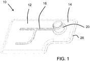
- a fluid filter 10 manufactured according to the method of the present disclosure includes a filter body 12 formed of a porous filtration material 14 and a plastic support structure 16 joined to the filter body.
- the fluid filter 10 defines a horizontal axis and a vertical axis.
- the manufacturing method of the present disclosure includes performing a first additive manufacturing step, positioning the porous filtration material, performing a second additive manufacturing step, folding the porous filtration material or adding a second layer of porous filtration material, and connecting the two layers of porous filtration material at a seam.
- additive manufacturing includes the use of a computer, three dimensional modeling software, machine equipment, such as a three dimensional printer, and layering material, such as a plastic that can be discharged from the printer.
- a computer model or sketch is produced using the three dimensional software and the equipment or printer lays down or adds successive layers of discharged plastic material, in a layer-upon-layer fashion to fabricate a three dimensional object.
- the first additive manufacturing step of the method of the present disclosure forms an initial portion 18 of the support structure 16.
- the initial portion 18 may be built up layer upon layer to increase the height of the initial portion 18 based on the predetermined design.
- the support structure is in the shape of an "h"; however, the support structure may be formed in any other suitable shape and size, and include any number of supports based on the desired filter configuration.
- the number of discrete pillars can range from one to more than twenty depending on the size and shape of the filter.
- the initial portion 18 may be a plurality of discrete pillars. Providing the initial portion 18 of the support structure 16 as discrete pillars reduces the surface area of the initial portion 18 and therefore reduces the area of the support structure 16 that will be in contact with the filtration material, thereby increasing the filtering area of the filter.
- the discrete pillars of the initial portion ultimately may be connected only indirectly through the porous material, i.e. they are not in direct contact.
- the initial portion 18 of the support structure 16 may alternatively be formed as a continuous, interconnected piece, or may begin as discrete pillars which are then joined together by additional layers from the additive manufacturing process.
- FIGS. 4B-4E show cross-sectional views of the initial portion of the support structure of FIGS. 2 and 3 , these are not intended to limit the breadth of limitless sizes and shapes of the support structure.
- the first additive manufacturing step may also include forming an initial portion 21 of a connector port 20 along with the initial portion 18 of the support structure.
- the initial portion 21 of the connector port 20 may similarly be discrete pillars or connected as a continuous piece of material.
- the first additive manufacturing step may include forming at least one connection projection 19 integral with and extending from the initial portion 18 of the support structure 16.
- the connection projection 19 may extend in a direction parallel to the vertical axis of the filter 10.
- the connection projection 19 is formed having a predetermined shape and a predetermined height, and is preferably smaller in area than the initial portion 18.
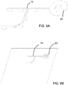
- Various shapes of the connection projections 19 are shown in FIGS. 5A , 6A , 7A , 8A , and 9A .
- the secondary portion 22 of the support structure 16 may be formed as a continuation of the at least one connection projection 19 during the second additive manufacturing step, such that the secondary portion 22 of the support structure 16 is spaced apart from the initial portion 18 of the support structure 16 at a distance equal to the height of the connection projection 19.
- the height of the at least one connection projection may correspond to a thickness of the porous filtration material 14.
- the method may further include the step of forming at least one cut-thru hole, opening or slit as a passageway 17 through the porous filtration material 14 in the direction parallel to the vertical axis of the filter.
- the at least one passageway 17 may correspond to the size and shape of the at least one connection projection 19.
- the step of positioning the porous filtration material 14 above the initial portion 18 of the support structure 16 may include aligning the at least one connection projection 19 within the passageway 17 in the porous filtration material 14.
- Providing the support structure 16 with the connection projections 19 and providing the porous filtration material 14 with passageways 17 allows the plastic layers formed during the additive manufacturing steps to bond directly to one another rather than having an intervening layer of porous filtration material 14. This may be particularly beneficial when the porous filtration material 14 is particularly dense or contains particularly small pores.
- the passageway 17 may be omitted based on filter design parameters. For example, the passageway 17 may be omitted when using coarse filtration material that has a propensity of pore or mesh openings that are greater than 40-70 micron. The coarse filtration material provides an opening for bonding of the support structure material through the mesh.
- connection projection(s) 19 may have various shapes and configurations.
- the connection projections are dots.
- the number of connection projections 19 may be varied based on design requirements.
- the connection projection 19 is a pattern of dots connected by bars.
- the connection projection 19 is a plurality of linear bars, and in FIG. 9A , the connection projections 19 are discrete bars or rectangles configured in T-shapes.
- the method further includes positioning the porous filtration material 14 above or on the initial portion 18 of the support structure 16.
- a single layer or a plurality of layers of porous filtration material may be layered above or on the initial portion 18 of the support structure 16.
- the porous filtration material 14 may be similarly positioned above or on the initial portion 21 of the connection port 20 in instances when the first additive manufacturing step includes forming an initial portion 21 of a connector port 20.
- the manufacturing method continues by performing a second additive manufacturing step to form a secondary portion 22 of the support structure 16 as a continuation of the initial portion 18 of the support structure 16 such that the porous filtration material 14 is positioned between the initial 18 and secondary portions 22, thereby joining the support structure to the filtration material.
- the portions 18 and 22 of the support structure 16 are joined together through the filtration material 14, e.g. either directly or at the connection projection(s) 19.
- the secondary portion 22 of the support structure 16 may be formed as a continuous piece, as shown in FIG. 10 , or may be formed as a plurality of discrete pillars.
- the secondary portion 22 is formed above the initial portion 18 of the support structure 16; however the secondary portion 22 need not be identical in shape or size as the initial portion 18.
- the initial portion 18 may be formed as discrete pillars, while the secondary portion is formed as a connected, continuous piece, or vice versa.
- both portions may be continuous or discrete.
- the second additive manufacturing step may also include forming a secondary portion 23 of the connector port 20.
- the porous filtration material 14 is positioned between a plurality of layers of the connector port 20, namely between the initial portion 21 and the secondary portion 23 of the connector port 20, thereby joining the connector port 20 to the filtration material 14.
- additional additive manufacturing steps may be undertaken to continue to form details of the connector port 20.
- Initial portions 18, 21 may be formed in different sizes and shapes than the secondary portions 22, 23, extend laterally therefrom, and may have varying cross-sections. These initial portions 18, 21 will ultimately lie within the interior of the filter.
- the method continues by positioning a first portion 24 of the porous filtration material 14 to overlay a second portion 26 of the porous filtration material 14. This may be accomplished by folding the layer of porous filtration material 14 upon itself or by adding a second discrete layer of porous filtration material 14. As shown in FIG. 14B , the overlaying first portion 24 and second portion 26 of the porous filtration material 14 results in one of the initial portion 18 of the support structure 16 or the secondary portion 22 of the support structure 16 being positioned between the first portion 24 and the second portion 26 of the porous filtration material. Likewise, the initial portion 21 or secondary portion 23 of the connector port will be positioned between the portions 24 and 26 of the filtration material 14 if a connector port was formed in the first or second additive manufacturing steps.
- the method further includes connecting the first portion 24 of the porous filtration material 14 to the second portion 26 of the porous filtration material 14 at a seam 28 to define a pocket within the filter body 12 between the first portion 24 and second portion 26 of the porous filtration material 14.
- the first portion 24 and second portion 26 of the porous filtration material may be connected around the entire perimeter of the filtration material 14 or may be connected around only a portion of the perimeter of the filtration material 14, for example when the single layer of porous filtration material 14 is folded.
- Porous filtration material 14 is secured along its periphery to direct fluid flow through the porous filtration material 14 and axially out the connector port 20.
- the support structure 16 provides structure and rigidity to the filtration material 14 that otherwise is not self-supporting.
- the support structure 16 additionally helps to maintain spacing between the first 24 and second portions 26 of the filtration material 14, e.g. via initial portions 18, 21, so the filter 10 retains its desired efficiency.
- the support structure only need be connected to one portion (e.g. first portion 24) of the porous filtration material 14, and the other portion (e.g. second portion 26) which forms one entire side of the filter, is completely open and free from obstruction.
- the porous filtration material 14 may be connected on both sides or neither side of the filter to the support structure.
- a plurality of different plastic materials may be used during the first and second additive manufacturing steps to form at least one living hinge on the support structure 16.
- a living hinge 25 is formed between sections of the support structure 16 to allow easier bending of the filter, e.g. at a predetermined point and degree.
- a plurality of materials may be used during the first and second additive manufacturing steps to form at least one sealing region on the support structure 16.
- a seal 29 may be integrally formed on the connector 20.
- the plurality of materials may include plastics and elastomerics. This sealing region functions as a compressible or pliable surface that deforms during filter use to create a seal with a mating component.
- the support structure 16 may be formed having a non-uniform cross sectional shape in the vertical axis direction.
- FIG. 15 shows a filter or strainer for filtering fluids in a fluid system manufactured according to an exemplary manufacturing method not according to the present invention.
- the fluid filter 10 comprises a porous filtration material 14 and a support structure 16.
- the method includes forming the support structure 16 one layer at a time using additive manufacturing.
- the support structure 16 may have any predetermined geometry.
- layers of plastic material may be laid down repeatedly until the structure achieves a desired height.
- the method further includes layering a sheet or sheets of the porous filtration material 14 between a plurality of layers of the support structure 16.
- the steps of the method may be iteratively performed a predetermined number of times, as shown in FIGS. 18 and 19 . As shown in FIGS.
- the support structure 16 may be formed to include a connector port 20.
- the support structure 16 may be formed having a non-uniform cross sectional shape in a vertical direction.
- Sheets of filtration material 14 may be layered within the support structure 16 spaced apart at predetermined increments.
- a plurality of plastic materials may be used during the additive manufacturing forming step to form at least one living hinge and/or at least one sealing region on the support structure 16.
- the filter formed according to the exemplary manufacturing method may be a flat disk with support structure 16 and porous filtration material 14.
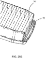
- the filter formed according to the exemplary manufacturing method not according to the present invention may be formed with the support structure 16 around pleated porous filtration material 30.
- This pleated porous filtration material 30 is porous filtration material 14 that has been folded into pleats to increase the surface area.
- the support structure 16 is formed using the additive manufacturing forming process around the sides and edges of the pleated porous filtration material.
Landscapes
- Chemical & Material Sciences (AREA)
- Engineering & Computer Science (AREA)
- Materials Engineering (AREA)
- Chemical Kinetics & Catalysis (AREA)
- Manufacturing & Machinery (AREA)
- Physics & Mathematics (AREA)
- Mechanical Engineering (AREA)
- Optics & Photonics (AREA)
- Filtering Materials (AREA)
- Filtration Of Liquid (AREA)
Description
- The present disclosure relates generally to a method of manufacturing strainers or in-tank filters commonly used in fluid tanks, and more particularly a method of manufacturing such filters using additive manufacturing.
- The statements in this section merely provide background information related to the present disclosure and may not constitute prior art.
- Generally, filters and strainers, for example fuel filters, urea filters and coarse filters, are installed into a fluid system to filter impurities and damaging particles from the fluid system. Such filters may be conventional sock style filters comprised of layers of flat sheets of filtration media sealed together at the outer perimeter edges to form a pocket inside the filter between the layers of filtration media. These filters may be installed in a liquid tank, i.e. a fuel tank. Sock style in-tank filters are used for filtering or removing contamination from a fuel or other filtered fluid. Strainers, such as coarse filters, may be installed in a conduit or pipe in which the fluid flows to catch larger debris or contaminants. Additionally, the filters may be conventional pleated or flat formed filters used for installing into a housing for filtering or removing contamination from air or other fluid.
- Generally, filters and strainers include a filtration component and a structural component. The filtration component is typically a porous filtration material with a predetermined pore size to allow a fluid to pass through the material while preventing any undesired particulates that are larger than the pore size from passing. The porous material typically is not self-supporting, i.e. the material tends to collapse or distort when fluid is passed through it. In some instances, distortion of the filtration material may include the layers of the filtration material bunching together or compressing, which may result in the filter being less effective.
- The distortion of the filtration material is typically reduced or prevented by providing a structural component within or around the porous filtration material. The structural component typically is sufficiently rigid to withstand the force of the fluid as it passes through the filter and the force exerted on the filtration material by the filtered particulates. The structural component may also assist in maintaining a desired shape of the filter and a desired spacing between the layers of the filtration material. The structural component is typically a molded piece of plastic or multiple pieces of molded plastic to provide support and rigidity to the porous filtration material. Additionally, the structural component may assist in maintaining the desired spacing between layers of the porous filtration material as the material is subjected to the force of the fluid flowing across the filtration material.
- Typically, the structural component is formed by a molding process. For in-tank filters this process may be insert molding. Insert molding typically requires extensive development time and investment to design, produce, and test new mold dies and tooling. We have discovered that due to these limitations, the insert molding process is not well-suited for producing cost-effective prototypes or low volume productions. The insert molding process additionally limits the shape and design of the structural components. For example, insert molding is generally limited to forming simple, continuous shapes having a uniform cross-section. Any complexity in the shape of the structural component typically results in additional molding steps, additional tool cavities and complexity, and additional labor, which increase production time and costs. We have also discovered that the tools used in the insert molding process are designed to crush the filtration material around the areas which they mold to reduce flash, thereby reducing filtering area and the filtration performance of the filter. Likewise, the structural component itself can block the pores of the filtration material, thereby reducing filtering area and the filtration performance of the filter.
-
US 2016/107106 A1 discloses a fluid filter apparatus which has been produced by using adaptive manufacturing. Two print heads are used, one for organic and one for inorganic material, to print a filter layer by layer. The inorganic material is included in solid spaces of the filter and coalesces during the sintering process. The organic material is included in void spaces of the filter and decomposes during the sintering process. In particular, the fluid filter apparatus comprising a support structure and filtration material is integrally formed in one single additive manufacturing step. -
US 5 902 480 A discloses an in-tank fuel filter which is provided inside a fuel tank. The fuel filter comprises upper and lower composite panels. Ribs or separators are provided between and molded to the upper and lower composite panels in order to separate the upper and lower composite panels and maintain an interior space and fuel flow. - Further areas of applicability will become apparent from the description provided herein. It should be understood that the description and specific examples are intended for purposes of illustration only and are not intended to limit the scope of the present disclosure.
- The present disclosure provides a method of manufacturing a strainer or filter for filtering fluids, wherein the fluid filter comprises a filter body formed of a porous filtration material and a rigid or semi-rigid support structure, such as from plastic, joined to the filter body, the fluid filter defining horizontal and vertical axes, and the porous filtration material having a first portion and a second portion. The manufacturing method includes performing a first additive manufacturing step to form an initial portion of the support structure; positioning the first portion of the porous filtration material above or on the initial portion of the support structure; performing a second additive manufacturing step to form a secondary portion of the support structure as a continuation of the initial portion of the support structure such that the first portion of the porous filtration material is positioned between the initial and secondary portions, thereby joining the initial and secondary portions together through the porous filtration material and joining the support structure to the filtration material; positioning a first portion of the porous filtration material to overlay a second portion of the porous filtration material; and connecting the first portion of the porous filtration material to the second portion of the porous filtration material at a seam or fold to define a pocket within the filter body between the first portion and second portion of the porous filtration material, the support structure configured to maintain spacing between the first and second portions of the filtration material.
- According to one form of the present disclosure, the initial portion of the support structure formed during the first additive manufacturing step may be plurality of discrete pillars. The discrete pillars may be indirectly connected through the porous filtration material. According to one form of the present disclosure, the first additive manufacturing step may include forming at least one connection projection integral with and extending from the initial portion of the support structure. The connection projection may extend in a direction parallel to the vertical axis of the filter. The connection projection is formed having a predetermined shape and a predetermined height. When the initial portion of the support structure includes the connection projection, the secondary portion of the support structure may be formed as a continuation of at least one connection projection during the second additive manufacturing step such that the secondary portion of the support structure is spaced apart from the initial portion of the support structure at a distance equal to the height of the connection projection. The height of at least one connection projection may correspond to a thickness of the porous filtration material.
- According to one form of the present disclosure, the method may further include the step of forming at least one passageway through the porous filtration material in the direction parallel to the vertical axis. The at least one passageway may correspond to the shape of the at least one connection projection. According to this form of the present disclosure, the step of positioning the first portion of the porous filtration material above or on the initial portion of the support structure may include aligning the at least one connection projection within the at least one passageway in the porous filtration material.
- According to various forms of the present disclosure, the support structure may be formed having a non-uniform cross sectional shape. Additionally, the secondary portion of the support structure formed during the second additive manufacturing step may be a plurality of discrete pillars.
- Additionally, the method may further include the step of forming an initial portion of a connector port during the first additive manufacturing step, positioning the first portion of the porous filtration material above or on the initial portion of the connector port, and forming a secondary portion of the connector port during the second additive manufacturing step, such that the porous filtration material is positioned between a plurality of layers of the connector port, thereby joining the connector port to the filtration material.
- According to various forms of the present disclosure, a plurality of different plastic materials may be used during the first and second additive manufacturing steps to form at least one living hinge on the support structure. Additionally, a plurality of materials, such as plastics and elastomerics, may be used during the first and second additive manufacturing steps to form at least one sealing region on the support structure.
- Further areas of applicability will become apparent from the description provided herein. It should be understood that the description and specific examples are intended for purposes of illustration only and are not intended to limit the scope of the present disclosure.
- In order that the disclosure may be well understood, there will now be described various forms thereof, given by way of example, reference being made to the accompanying drawings, in which:
-
FIG. 1 is an isometric view of a fluid filter manufactured according to one form of a manufacturing method of the present disclosure; -
FIG. 2 is an isometric view of an initial portion of a support structure formed in a first additive manufacturing step of according to the present disclosure; -
FIG. 3 is an isometric view of the initial portion of the support structure further formed upon the initial portion of the support structure ofFIG. 2 ; -
FIG. 4A is an isometric view of an alternative initial portion of the support structure further formed upon the initial portion of the support structure ofFIG. 2 ; -
FIGS. 4B-4E are cross-sectional views of the initial portion of the support structure ofFIG. 2 , these are not intended to limit the breadth of limitless sizes and shapes of the support structure; -
FIGS. 5A ,6A ,7A ,8A , and9A are isometric views of various forms of an initial portion of a support structure having connection projections formed during the first additive manufacturing step of the method according to various forms of the present disclosure, these are not intended to limit the breadth of limitless sizes and shapes of the support structure; -
FIGS. 5B ,6B ,7B ,8B , and9B are isometric views of the initial portion of a support structure ofFIGS. 5A ,6A ,7A ,8A , and9A , respectively, with porous filtration material positioned according to the positioning step the present disclosure, these are not intended to limit the breadth of limitless sizes and shapes of the support structure; -
FIG. 10 is an isometric view of the fluid filter after the positioning step of one form of the manufacturing method according to the present disclosure; -
FIG. 11A to FIG. 13B are isometric views showing a method for manufacturing a fluid filter having a connector port according to one form of the present disclosure; -
FIG. 14A is an isometric view of a folding step of a method for manufacturing the fluid filter ofFIG. 1 ; -
FIG. 14B is a cross-sectional view of the folding step of a method for manufacturing the fluid filter ofFIG. 1 ; -
FIG. 15 is an isometric view of a fluid filter manufactured according to an exemplary manufacturing method; -
FIG. 16 is an isometric view of a first layer of a support structure of the fluid filter forFIG 15 formed using additive manufacturing; -
FIG. 17 is an isometric view of a sheet of porous filtration material layered between a plurality of layers of the support structure of the filter ofFIG. 15 ; -
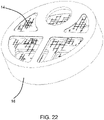
FIG. 18 to FIG. 24 are isometric views of the fluid filter ofFIG. 15 in various stages of the manufacturing method; -
FIG. 25A is an isometric view of an exemplary porous filtration material that has been folded into pleats and formed into the shape of the filter body; and -
FIG. 25B is an isometric view of the porous filtration material ofFIG. 25A processed with a support structure around the filtration material to form the shape of the filter body. - The drawings described herein are for illustration purposes only and are not intended to limit the scope of the present disclosure in any way.
- The following description is merely exemplary in nature and is not intended to limit the present disclosure, application, or uses. It should be understood that throughout the drawings, corresponding reference numerals indicate like or corresponding parts and features.
- Further areas of applicability will become apparent from the description provided herein. It should be understood that the description and specific examples are intended for purposes of illustration only and are not intended to limit the scope of the present disclosure.
- The present disclosure provides a method of manufacturing a
fluid filter 10 for filtering liquids. As shown inFIG. 1 , afluid filter 10 manufactured according to the method of the present disclosure includes afilter body 12 formed of aporous filtration material 14 and aplastic support structure 16 joined to the filter body. Thefluid filter 10 defines a horizontal axis and a vertical axis. - The manufacturing method of the present disclosure includes performing a first additive manufacturing step, positioning the porous filtration material, performing a second additive manufacturing step, folding the porous filtration material or adding a second layer of porous filtration material, and connecting the two layers of porous filtration material at a seam. Generally, additive manufacturing includes the use of a computer, three dimensional modeling software, machine equipment, such as a three dimensional printer, and layering material, such as a plastic that can be discharged from the printer. A computer model or sketch is produced using the three dimensional software and the equipment or printer lays down or adds successive layers of discharged plastic material, in a layer-upon-layer fashion to fabricate a three dimensional object.
- As shown in
FIG. 2 , the first additive manufacturing step of the method of the present disclosure forms aninitial portion 18 of thesupport structure 16. Theinitial portion 18 may be built up layer upon layer to increase the height of theinitial portion 18 based on the predetermined design. As shown in the figures, the support structure is in the shape of an "h"; however, the support structure may be formed in any other suitable shape and size, and include any number of supports based on the desired filter configuration. The number of discrete pillars can range from one to more than twenty depending on the size and shape of the filter. - As shown in
FIG. 3 , theinitial portion 18 may be a plurality of discrete pillars. Providing theinitial portion 18 of thesupport structure 16 as discrete pillars reduces the surface area of theinitial portion 18 and therefore reduces the area of thesupport structure 16 that will be in contact with the filtration material, thereby increasing the filtering area of the filter. The discrete pillars of the initial portion ultimately may be connected only indirectly through the porous material, i.e. they are not in direct contact. As shown inFIG. 4A , theinitial portion 18 of thesupport structure 16 may alternatively be formed as a continuous, interconnected piece, or may begin as discrete pillars which are then joined together by additional layers from the additive manufacturing process.FIGS. 4B-4E show cross-sectional views of the initial portion of the support structure ofFIGS. 2 and 3 , these are not intended to limit the breadth of limitless sizes and shapes of the support structure. - According to the method of the present disclosure, the first additive manufacturing step, as shown in
FIG. 2 and 3 , may also include forming aninitial portion 21 of aconnector port 20 along with theinitial portion 18 of the support structure. Theinitial portion 21 of theconnector port 20 may similarly be discrete pillars or connected as a continuous piece of material. - As shown in
FIGS. 5A ,6A ,7A ,8A , and9A , the first additive manufacturing step may include forming at least oneconnection projection 19 integral with and extending from theinitial portion 18 of thesupport structure 16. Theconnection projection 19 may extend in a direction parallel to the vertical axis of thefilter 10. Theconnection projection 19 is formed having a predetermined shape and a predetermined height, and is preferably smaller in area than theinitial portion 18. Various shapes of theconnection projections 19 are shown inFIGS. 5A ,6A ,7A ,8A , and9A . - When the
initial portion 18 of thesupport structure 16 includes theconnection projection 19, thesecondary portion 22 of the support structure 16 (discussed further herein) may be formed as a continuation of the at least oneconnection projection 19 during the second additive manufacturing step, such that thesecondary portion 22 of thesupport structure 16 is spaced apart from theinitial portion 18 of thesupport structure 16 at a distance equal to the height of theconnection projection 19. The height of the at least one connection projection may correspond to a thickness of theporous filtration material 14. - As shown in
FIGS. 5B ,6B ,7B ,8B , and9B , according to one form of the present disclosure, the method may further include the step of forming at least one cut-thru hole, opening or slit as apassageway 17 through theporous filtration material 14 in the direction parallel to the vertical axis of the filter. The at least onepassageway 17 may correspond to the size and shape of the at least oneconnection projection 19. According to this form of the present disclosure, the step of positioning theporous filtration material 14 above theinitial portion 18 of thesupport structure 16 may include aligning the at least oneconnection projection 19 within thepassageway 17 in theporous filtration material 14. Providing thesupport structure 16 with theconnection projections 19 and providing theporous filtration material 14 withpassageways 17 allows the plastic layers formed during the additive manufacturing steps to bond directly to one another rather than having an intervening layer ofporous filtration material 14. This may be particularly beneficial when theporous filtration material 14 is particularly dense or contains particularly small pores. Thepassageway 17 may be omitted based on filter design parameters. For example, thepassageway 17 may be omitted when using coarse filtration material that has a propensity of pore or mesh openings that are greater than 40-70 micron. The coarse filtration material provides an opening for bonding of the support structure material through the mesh. - As shown in
FIGS. 5A-9B , the connection projection(s) 19 may have various shapes and configurations. For example, inFIGS. 5A and7A , the connection projections are dots. The number ofconnection projections 19 may be varied based on design requirements. InFIG. 6A , theconnection projection 19 is a pattern of dots connected by bars. As shown inFIG. 8A , theconnection projection 19 is a plurality of linear bars, and inFIG. 9A , theconnection projections 19 are discrete bars or rectangles configured in T-shapes. - As shown in
FIGS. 5B ,6B ,7B ,8B , and9B , the method further includes positioning theporous filtration material 14 above or on theinitial portion 18 of thesupport structure 16. A single layer or a plurality of layers of porous filtration material may be layered above or on theinitial portion 18 of thesupport structure 16. Theporous filtration material 14 may be similarly positioned above or on theinitial portion 21 of theconnection port 20 in instances when the first additive manufacturing step includes forming aninitial portion 21 of aconnector port 20. - As shown in
FIG. 10 , the manufacturing method continues by performing a second additive manufacturing step to form asecondary portion 22 of thesupport structure 16 as a continuation of theinitial portion 18 of thesupport structure 16 such that theporous filtration material 14 is positioned between the initial 18 andsecondary portions 22, thereby joining the support structure to the filtration material. In other words, theportions support structure 16 are joined together through thefiltration material 14, e.g. either directly or at the connection projection(s) 19. Thesecondary portion 22 of thesupport structure 16 may be formed as a continuous piece, as shown inFIG. 10 , or may be formed as a plurality of discrete pillars. Thesecondary portion 22 is formed above theinitial portion 18 of thesupport structure 16; however thesecondary portion 22 need not be identical in shape or size as theinitial portion 18. For example, theinitial portion 18 may be formed as discrete pillars, while the secondary portion is formed as a connected, continuous piece, or vice versa. Alternatively, both portions may be continuous or discrete. - The second additive manufacturing step may also include forming a
secondary portion 23 of theconnector port 20. In this case, theporous filtration material 14 is positioned between a plurality of layers of theconnector port 20, namely between theinitial portion 21 and thesecondary portion 23 of theconnector port 20, thereby joining theconnector port 20 to thefiltration material 14. As shown inFIG 11A to 13B , additional additive manufacturing steps may be undertaken to continue to form details of theconnector port 20.Initial portions secondary portions initial portions - As shown in
FIG. 14A , the method continues by positioning afirst portion 24 of theporous filtration material 14 to overlay asecond portion 26 of theporous filtration material 14. This may be accomplished by folding the layer ofporous filtration material 14 upon itself or by adding a second discrete layer ofporous filtration material 14. As shown inFIG. 14B , the overlayingfirst portion 24 andsecond portion 26 of theporous filtration material 14 results in one of theinitial portion 18 of thesupport structure 16 or thesecondary portion 22 of thesupport structure 16 being positioned between thefirst portion 24 and thesecond portion 26 of the porous filtration material. Likewise, theinitial portion 21 orsecondary portion 23 of the connector port will be positioned between theportions filtration material 14 if a connector port was formed in the first or second additive manufacturing steps. - Referring again to
FIG. 1 along withFIG. 14A and Fig. 14B , the method further includes connecting thefirst portion 24 of theporous filtration material 14 to thesecond portion 26 of theporous filtration material 14 at aseam 28 to define a pocket within thefilter body 12 between thefirst portion 24 andsecond portion 26 of theporous filtration material 14. Thefirst portion 24 andsecond portion 26 of the porous filtration material may be connected around the entire perimeter of thefiltration material 14 or may be connected around only a portion of the perimeter of thefiltration material 14, for example when the single layer ofporous filtration material 14 is folded.Porous filtration material 14 is secured along its periphery to direct fluid flow through theporous filtration material 14 and axially out theconnector port 20. - The
support structure 16 provides structure and rigidity to thefiltration material 14 that otherwise is not self-supporting. Thesupport structure 16 additionally helps to maintain spacing between the first 24 andsecond portions 26 of thefiltration material 14, e.g. viainitial portions filter 10 retains its desired efficiency. - It will also be recognized that the support structure only need be connected to one portion (e.g. first portion 24) of the
porous filtration material 14, and the other portion (e.g. second portion 26) which forms one entire side of the filter, is completely open and free from obstruction. Alternately, theporous filtration material 14 may be connected on both sides or neither side of the filter to the support structure. - According to various forms of the present disclosure, a plurality of different plastic materials may be used during the first and second additive manufacturing steps to form at least one living hinge on the
support structure 16. For example, inFIG. 5A a livinghinge 25 is formed between sections of thesupport structure 16 to allow easier bending of the filter, e.g. at a predetermined point and degree. Additionally, a plurality of materials may be used during the first and second additive manufacturing steps to form at least one sealing region on thesupport structure 16. For example, aseal 29 may be integrally formed on theconnector 20. The plurality of materials may include plastics and elastomerics. This sealing region functions as a compressible or pliable surface that deforms during filter use to create a seal with a mating component. Additionally, according to various forms of the present disclosure, thesupport structure 16 may be formed having a non-uniform cross sectional shape in the vertical axis direction. -
FIG. 15 shows a filter or strainer for filtering fluids in a fluid system manufactured according to an exemplary manufacturing method not according to the present invention. Thefluid filter 10 comprises aporous filtration material 14 and asupport structure 16. As shown inFIG. 16 , the method includes forming thesupport structure 16 one layer at a time using additive manufacturing. Thesupport structure 16 may have any predetermined geometry. Using additive manufacturing, layers of plastic material may be laid down repeatedly until the structure achieves a desired height. As shown inFIG. 17 the method further includes layering a sheet or sheets of theporous filtration material 14 between a plurality of layers of thesupport structure 16. The steps of the method may be iteratively performed a predetermined number of times, as shown inFIGS. 18 and19 . As shown inFIGS. 23 and24 , thesupport structure 16, may be formed to include aconnector port 20. Thesupport structure 16 may be formed having a non-uniform cross sectional shape in a vertical direction. Sheets offiltration material 14 may be layered within thesupport structure 16 spaced apart at predetermined increments. A plurality of plastic materials may be used during the additive manufacturing forming step to form at least one living hinge and/or at least one sealing region on thesupport structure 16. - As shown in
FIG. 17 , the filter formed according to the exemplary manufacturing method may be a flat disk withsupport structure 16 andporous filtration material 14. - Alternately, as shown in
FIG. 25A and25B , the filter formed according to the exemplary manufacturing method not according to the present invention may be formed with thesupport structure 16 around pleatedporous filtration material 30. This pleatedporous filtration material 30 isporous filtration material 14 that has been folded into pleats to increase the surface area. Thesupport structure 16 is formed using the additive manufacturing forming process around the sides and edges of the pleated porous filtration material.
Claims (13)
- A method of manufacturing a filter (10) for filtering fluids, wherein the filter (10) comprises a filter body (12) formed of a porous filtration material (14) and a plastic support structure (16), the filter (10) defining horizontal and vertical axes, the porous filtration material (14) having a first portion (24) and a second portion (26) and the method comprising:performing a first additive manufacturing step to form an initial portion (18) of the support structure (16);positioning the first portion (24) of the porous filtration material above or on the initial portion (18) of the support structure (16);performing a second additive manufacturing step to form a secondary portion (22) of the support structure (16) as a continuation of the initial portion (18) of the support structure (16) such that the first portion (24) of the porous filtration material (14) is positioned between the initial and secondary portions (18, 22), thereby joining the initial and secondary portions (18, 22) together through the porous filtration material (14) and joining the support structure (16) to the first portion (24) of the porous filtration material (14);positioning the first portion (24) of the porous filtration material (14) to overlay the second portion (26) of the porous filtration material (14); andconnecting the first portion (24) of the porous filtration material (14) to the second portion (26) of the porous filtration material (14) at a seam (28) to define a pocket within the filter body (12) between the first portion (24) and the second portion (26) of the porous filtration material (14), the support structure (16) configured to maintain spacing between the first and second portions (24, 26) of the filtration material (14).
- The method of claim 1, wherein the initial portion (18) of the support structure (16) formed during the first additive manufacturing step is a plurality of discrete pillars.
- The method of claim 2, wherein the discrete pillars are indirectly connected through the porous filtration material (14).
- The method of claim 1, wherein the first additive manufacturing step includes forming at least one connection projection (19) integral with and extending from the initial portion (18) of the support structure (16) in a direction parallel to the vertical axis, wherein the at least one connection projection (19) has a predetermined shape and a predetermined height.
- The method of claim 4, wherein the secondary portion (22) of the support structure (16) is formed as a continuation of the at least one connection projection (19) during the second additive manufacturing step such that the secondary portion (22) of the support structure (16) is spaced apart from the initial portion (18) of the support structure (16) at a distance equal to the height of the connection projection (19).
- The method of claim 4, wherein the height of the at least one connection projection (19) corresponds to a thickness of the porous filtration material (14).
- The method of claim 4, further comprising the step of forming at least one passageway (17) through the porous filtration material (14) in the direction parallel to the vertical axis, wherein the at least one passageway (17) corresponds to the shape of the at least one connection projection (19).
- The method of claim 7, wherein the step of positioning the first portion (24) of the porous filtration material (14) above or on the initial portion (18) of the support structure (16) includes aligning the at least one connection projection (19) within the at least one passageway (17) in the porous filtration material (14).
- The method of claim 1, wherein the support structure (16) is formed having a non-uniform cross sectional shape in a direction parallel to the vertical axis.
- The method of claim 1, wherein the secondary portion (22) of the support structure (16) formed during the second additive manufacturing step is a plurality of discrete pillars.
- The method of claim 1, further comprising the step of forming an initial portion (21) of a connector port (20) during the first additive manufacturing step, positioning the first portion (24) of the porous filtration material (14) on the initial portion (21) of the connector port (20), and forming a secondary portion (23) of the connector port (20) during the second additive manufacturing step, such that the porous filtration material (14) is positioned between a plurality of layers of the connector port (20), thereby joining the connector port (20) to the filtration material (14).
- The method of claim 1, wherein a plurality of different plastic or elastomeric materials are used during the first and second additive manufacturing steps to form at least one living hinge (25) on the support structure (16).
- The method of claim 1, wherein a plurality of different plastic or elastomeric materials are used during the first and second additive manufacturing steps to form at least one sealing region (29) on the support structure (16).
Applications Claiming Priority (2)
| Application Number | Priority Date | Filing Date | Title |
|---|---|---|---|
| US201762446128P | 2017-01-13 | 2017-01-13 | |
| PCT/US2017/068258 WO2018132251A1 (en) | 2017-01-13 | 2017-12-22 | Method of manufacturing a fluid filter |
Publications (4)
| Publication Number | Publication Date |
|---|---|
| EP3568224A1 EP3568224A1 (en) | 2019-11-20 |
| EP3568224A4 EP3568224A4 (en) | 2020-08-26 |
| EP3568224B1 true EP3568224B1 (en) | 2022-05-25 |
| EP3568224B8 EP3568224B8 (en) | 2022-09-28 |
Family
ID=62838882
Family Applications (1)
| Application Number | Title | Priority Date | Filing Date |
|---|---|---|---|
| EP17891695.3A Active EP3568224B8 (en) | 2017-01-13 | 2017-12-22 | Method of manufacturing a fluid filter |
Country Status (7)
| Country | Link |
|---|---|
| US (1) | US10898834B2 (en) |
| EP (1) | EP3568224B8 (en) |
| JP (1) | JP6928672B2 (en) |
| KR (1) | KR102338325B1 (en) |
| CN (1) | CN110475597B (en) |
| MX (1) | MX2019008374A (en) |
| WO (1) | WO2018132251A1 (en) |
Families Citing this family (5)
| Publication number | Priority date | Publication date | Assignee | Title |
|---|---|---|---|---|
| US11173438B2 (en) * | 2018-09-14 | 2021-11-16 | Caterpillar Inc. | Filter having tracer material |
| US20200139283A1 (en) | 2018-11-02 | 2020-05-07 | Caterpillar Inc. | Filtration media packs formed using a dissolvable material |
| US11020690B2 (en) | 2018-12-06 | 2021-06-01 | Caterpillar Inc. | 3D printed filter center tube |
| WO2021216758A1 (en) * | 2020-04-22 | 2021-10-28 | The Exone Company | Additively manufactured reusable air filters |
| DE102020124689A1 (en) * | 2020-09-22 | 2022-03-24 | Herding Gmbh Filtertechnik | Inherently stable porous filter element and method for producing such a filter element |
Family Cites Families (13)
| Publication number | Priority date | Publication date | Assignee | Title |
|---|---|---|---|---|
| US4643981A (en) * | 1983-11-09 | 1987-02-17 | Akzo N.V. | Pressure filtration system |
| US5902480A (en) * | 1997-05-13 | 1999-05-11 | Kuss Corporation | Depth media in-tank fuel filter with extruded mesh shell |
| AU2001259568A1 (en) | 2000-05-05 | 2001-11-20 | Extraction Systems, Inc. | Filters employing both acidic polymers and physical-absorption media |
| EP1247558A1 (en) * | 2001-04-07 | 2002-10-09 | 3M Innovative Properties Company | A combination filter for filtering fluids |
| US7141198B2 (en) * | 2004-06-17 | 2006-11-28 | Millipore Corporation | Method for the manufacture of a composite filter plate |
| US8590158B2 (en) * | 2010-10-29 | 2013-11-26 | Corning Incorporated | Methods of making filter apparatus and fabricating a porous ceramic article |
| DE112014001464T5 (en) * | 2013-03-15 | 2016-02-18 | Pyrotek Incorporated | ceramic filter |
| FR3006606B1 (en) | 2013-06-11 | 2015-07-03 | Tech Avancees Et Membranes Industrielles | PROCESS FOR MANUFACTURING FILTRATION MEMBRANES BY ADDITIVE TECHNIQUE AND MEMBRANES OBTAINED |
| DE102013014688A1 (en) * | 2013-09-05 | 2015-03-05 | Mann + Hummel Gmbh | Filter element and method for producing the same |
| CN106488794B (en) * | 2014-05-22 | 2019-07-19 | 酷思滤清系统有限公司 | Form the filter medium for maintaining the flow channel by bag type filter |
| US20160107106A1 (en) * | 2014-10-15 | 2016-04-21 | Lawrence Livermore National Security, Llc | Printing engineered fluid filters |
| US10315148B2 (en) | 2014-11-03 | 2019-06-11 | Esa European Space Agency | Fluidic filter |
| TWI534006B (en) * | 2015-04-09 | 2016-05-21 | Filter element and its forming method |
-
2017
- 2017-12-22 CN CN201780083568.6A patent/CN110475597B/en active Active
- 2017-12-22 US US15/852,884 patent/US10898834B2/en active Active
- 2017-12-22 WO PCT/US2017/068258 patent/WO2018132251A1/en not_active Ceased
- 2017-12-22 MX MX2019008374A patent/MX2019008374A/en unknown
- 2017-12-22 JP JP2019559265A patent/JP6928672B2/en active Active
- 2017-12-22 KR KR1020197023381A patent/KR102338325B1/en active Active
- 2017-12-22 EP EP17891695.3A patent/EP3568224B8/en active Active
Also Published As
| Publication number | Publication date |
|---|---|
| KR20190104201A (en) | 2019-09-06 |
| MX2019008374A (en) | 2019-12-02 |
| KR102338325B1 (en) | 2021-12-10 |
| JP6928672B2 (en) | 2021-09-01 |
| US10898834B2 (en) | 2021-01-26 |
| EP3568224A1 (en) | 2019-11-20 |
| CN110475597A (en) | 2019-11-19 |
| EP3568224A4 (en) | 2020-08-26 |
| CN110475597B (en) | 2022-05-13 |
| WO2018132251A1 (en) | 2018-07-19 |
| JP2020505230A (en) | 2020-02-20 |
| US20180200650A1 (en) | 2018-07-19 |
| EP3568224B8 (en) | 2022-09-28 |
Similar Documents
| Publication | Publication Date | Title |
|---|---|---|
| US10898834B2 (en) | Method of manufacturing a fluid filter | |
| EP3413994B1 (en) | Panel filter with molded frame and integral seal | |
| CN102666162B (en) | Filter element and method for manufacturing filter element | |
| EP2906320B1 (en) | Self-supporting folded sheet material, filter elements | |
| US8216470B2 (en) | Multi-stage filter cartridge with polyurethane endcaps | |
| US7648546B2 (en) | Filter with variable pleat depth | |
| US8137546B2 (en) | Fuel filter device | |
| CA2866216C (en) | Air filter cartridge for i.c. motors, method for its manufacture and air filter incorporating said cartridge | |
| EP3145611B1 (en) | Forming filtration media for maintaining flow passage through a sock style filter | |
| US20170197165A1 (en) | Filter element with varied filter media pack characteristics | |
| JP7049336B2 (en) | Filter element | |
| JP2009503314A (en) | Fuel filter | |
| CN103118758B (en) | Improved filtering device for the fuel pump of a vehicle | |
| JP5368914B2 (en) | Oil strainer manufacturing method | |
| JP2014125989A (en) | Filter and oil strainer | |
| WO2024251489A1 (en) | Flat-filter filter element having at least two filter medium bodies, filter system and use of a flat-filter filter element |
Legal Events
| Date | Code | Title | Description |
|---|---|---|---|
| STAA | Information on the status of an ep patent application or granted ep patent |
Free format text: STATUS: THE INTERNATIONAL PUBLICATION HAS BEEN MADE |
|
| PUAI | Public reference made under article 153(3) epc to a published international application that has entered the european phase |
Free format text: ORIGINAL CODE: 0009012 |
|
| STAA | Information on the status of an ep patent application or granted ep patent |
Free format text: STATUS: REQUEST FOR EXAMINATION WAS MADE |
|
| 17P | Request for examination filed |
Effective date: 20190618 |
|
| AK | Designated contracting states |
Kind code of ref document: A1 Designated state(s): AL AT BE BG CH CY CZ DE DK EE ES FI FR GB GR HR HU IE IS IT LI LT LU LV MC MK MT NL NO PL PT RO RS SE SI SK SM TR |
|
| AX | Request for extension of the european patent |
Extension state: BA ME |
|
| DAV | Request for validation of the european patent (deleted) | ||
| DAX | Request for extension of the european patent (deleted) | ||
| A4 | Supplementary search report drawn up and despatched |
Effective date: 20200727 |
|
| RIC1 | Information provided on ipc code assigned before grant |
Ipc: B01D 46/00 20060101ALI20200721BHEP Ipc: B33Y 80/00 20150101ALI20200721BHEP Ipc: B29C 64/10 20170101ALI20200721BHEP Ipc: B01D 67/00 20060101ALI20200721BHEP Ipc: B01D 39/00 20060101AFI20200721BHEP Ipc: B29C 64/00 20170101ALI20200721BHEP |
|
| STAA | Information on the status of an ep patent application or granted ep patent |
Free format text: STATUS: EXAMINATION IS IN PROGRESS |
|
| 17Q | First examination report despatched |
Effective date: 20210707 |
|
| GRAP | Despatch of communication of intention to grant a patent |
Free format text: ORIGINAL CODE: EPIDOSNIGR1 |
|
| STAA | Information on the status of an ep patent application or granted ep patent |
Free format text: STATUS: GRANT OF PATENT IS INTENDED |
|
| INTG | Intention to grant announced |
Effective date: 20211208 |
|
| GRAS | Grant fee paid |
Free format text: ORIGINAL CODE: EPIDOSNIGR3 |
|
| GRAA | (expected) grant |
Free format text: ORIGINAL CODE: 0009210 |
|
| STAA | Information on the status of an ep patent application or granted ep patent |
Free format text: STATUS: THE PATENT HAS BEEN GRANTED |
|
| AK | Designated contracting states |
Kind code of ref document: B1 Designated state(s): AL AT BE BG CH CY CZ DE DK EE ES FI FR GB GR HR HU IE IS IT LI LT LU LV MC MK MT NL NO PL PT RO RS SE SI SK SM TR |
|
| REG | Reference to a national code |
Ref country code: GB Ref legal event code: FG4D |
|
| REG | Reference to a national code |
Ref country code: CH Ref legal event code: EP |
|
| REG | Reference to a national code |
Ref country code: AT Ref legal event code: REF Ref document number: 1494037 Country of ref document: AT Kind code of ref document: T Effective date: 20220615 Ref country code: DE Ref legal event code: R096 Ref document number: 602017057895 Country of ref document: DE |
|
| REG | Reference to a national code |
Ref country code: IE Ref legal event code: FG4D |
|
| GRAT | Correction requested after decision to grant or after decision to maintain patent in amended form |
Free format text: ORIGINAL CODE: EPIDOSNCDEC |
|
| REG | Reference to a national code |
Ref country code: CH Ref legal event code: PK Free format text: BERICHTIGUNG B8 |
|
| REG | Reference to a national code |
Ref country code: LT Ref legal event code: MG9D |
|
| REG | Reference to a national code |
Ref country code: DE Ref legal event code: R081 Ref document number: 602017057895 Country of ref document: DE Owner name: GVS FILTRATION INC., FINDLAY, US Free format text: FORMER OWNER: GVS FILTRATON, INC., FINDLAY, OH, US |
|
| RAP4 | Party data changed (patent owner data changed or rights of a patent transferred) |
Owner name: GVS FILTRATION INC. |
|
| REG | Reference to a national code |
Ref country code: NL Ref legal event code: MP Effective date: 20220525 |
|
| REG | Reference to a national code |
Ref country code: AT Ref legal event code: MK05 Ref document number: 1494037 Country of ref document: AT Kind code of ref document: T Effective date: 20220525 |
|
| PG25 | Lapsed in a contracting state [announced via postgrant information from national office to epo] |
Ref country code: SE Free format text: LAPSE BECAUSE OF FAILURE TO SUBMIT A TRANSLATION OF THE DESCRIPTION OR TO PAY THE FEE WITHIN THE PRESCRIBED TIME-LIMIT Effective date: 20220525 Ref country code: PT Free format text: LAPSE BECAUSE OF FAILURE TO SUBMIT A TRANSLATION OF THE DESCRIPTION OR TO PAY THE FEE WITHIN THE PRESCRIBED TIME-LIMIT Effective date: 20220926 Ref country code: NO Free format text: LAPSE BECAUSE OF FAILURE TO SUBMIT A TRANSLATION OF THE DESCRIPTION OR TO PAY THE FEE WITHIN THE PRESCRIBED TIME-LIMIT Effective date: 20220825 Ref country code: NL Free format text: LAPSE BECAUSE OF FAILURE TO SUBMIT A TRANSLATION OF THE DESCRIPTION OR TO PAY THE FEE WITHIN THE PRESCRIBED TIME-LIMIT Effective date: 20220525 Ref country code: LT Free format text: LAPSE BECAUSE OF FAILURE TO SUBMIT A TRANSLATION OF THE DESCRIPTION OR TO PAY THE FEE WITHIN THE PRESCRIBED TIME-LIMIT Effective date: 20220525 Ref country code: HR Free format text: LAPSE BECAUSE OF FAILURE TO SUBMIT A TRANSLATION OF THE DESCRIPTION OR TO PAY THE FEE WITHIN THE PRESCRIBED TIME-LIMIT Effective date: 20220525 Ref country code: GR Free format text: LAPSE BECAUSE OF FAILURE TO SUBMIT A TRANSLATION OF THE DESCRIPTION OR TO PAY THE FEE WITHIN THE PRESCRIBED TIME-LIMIT Effective date: 20220826 Ref country code: FI Free format text: LAPSE BECAUSE OF FAILURE TO SUBMIT A TRANSLATION OF THE DESCRIPTION OR TO PAY THE FEE WITHIN THE PRESCRIBED TIME-LIMIT Effective date: 20220525 Ref country code: ES Free format text: LAPSE BECAUSE OF FAILURE TO SUBMIT A TRANSLATION OF THE DESCRIPTION OR TO PAY THE FEE WITHIN THE PRESCRIBED TIME-LIMIT Effective date: 20220525 Ref country code: BG Free format text: LAPSE BECAUSE OF FAILURE TO SUBMIT A TRANSLATION OF THE DESCRIPTION OR TO PAY THE FEE WITHIN THE PRESCRIBED TIME-LIMIT Effective date: 20220825 Ref country code: AT Free format text: LAPSE BECAUSE OF FAILURE TO SUBMIT A TRANSLATION OF THE DESCRIPTION OR TO PAY THE FEE WITHIN THE PRESCRIBED TIME-LIMIT Effective date: 20220525 |
|
| PG25 | Lapsed in a contracting state [announced via postgrant information from national office to epo] |
Ref country code: RS Free format text: LAPSE BECAUSE OF FAILURE TO SUBMIT A TRANSLATION OF THE DESCRIPTION OR TO PAY THE FEE WITHIN THE PRESCRIBED TIME-LIMIT Effective date: 20220525 Ref country code: PL Free format text: LAPSE BECAUSE OF FAILURE TO SUBMIT A TRANSLATION OF THE DESCRIPTION OR TO PAY THE FEE WITHIN THE PRESCRIBED TIME-LIMIT Effective date: 20220525 Ref country code: LV Free format text: LAPSE BECAUSE OF FAILURE TO SUBMIT A TRANSLATION OF THE DESCRIPTION OR TO PAY THE FEE WITHIN THE PRESCRIBED TIME-LIMIT Effective date: 20220525 Ref country code: IS Free format text: LAPSE BECAUSE OF FAILURE TO SUBMIT A TRANSLATION OF THE DESCRIPTION OR TO PAY THE FEE WITHIN THE PRESCRIBED TIME-LIMIT Effective date: 20220925 |
|
| PG25 | Lapsed in a contracting state [announced via postgrant information from national office to epo] |
Ref country code: SM Free format text: LAPSE BECAUSE OF FAILURE TO SUBMIT A TRANSLATION OF THE DESCRIPTION OR TO PAY THE FEE WITHIN THE PRESCRIBED TIME-LIMIT Effective date: 20220525 Ref country code: SK Free format text: LAPSE BECAUSE OF FAILURE TO SUBMIT A TRANSLATION OF THE DESCRIPTION OR TO PAY THE FEE WITHIN THE PRESCRIBED TIME-LIMIT Effective date: 20220525 Ref country code: RO Free format text: LAPSE BECAUSE OF FAILURE TO SUBMIT A TRANSLATION OF THE DESCRIPTION OR TO PAY THE FEE WITHIN THE PRESCRIBED TIME-LIMIT Effective date: 20220525 Ref country code: EE Free format text: LAPSE BECAUSE OF FAILURE TO SUBMIT A TRANSLATION OF THE DESCRIPTION OR TO PAY THE FEE WITHIN THE PRESCRIBED TIME-LIMIT Effective date: 20220525 Ref country code: DK Free format text: LAPSE BECAUSE OF FAILURE TO SUBMIT A TRANSLATION OF THE DESCRIPTION OR TO PAY THE FEE WITHIN THE PRESCRIBED TIME-LIMIT Effective date: 20220525 Ref country code: CZ Free format text: LAPSE BECAUSE OF FAILURE TO SUBMIT A TRANSLATION OF THE DESCRIPTION OR TO PAY THE FEE WITHIN THE PRESCRIBED TIME-LIMIT Effective date: 20220525 |
|
| REG | Reference to a national code |
Ref country code: DE Ref legal event code: R097 Ref document number: 602017057895 Country of ref document: DE |
|
| PG25 | Lapsed in a contracting state [announced via postgrant information from national office to epo] |
Ref country code: AL Free format text: LAPSE BECAUSE OF FAILURE TO SUBMIT A TRANSLATION OF THE DESCRIPTION OR TO PAY THE FEE WITHIN THE PRESCRIBED TIME-LIMIT Effective date: 20220525 |
|
| PLBE | No opposition filed within time limit |
Free format text: ORIGINAL CODE: 0009261 |
|
| STAA | Information on the status of an ep patent application or granted ep patent |
Free format text: STATUS: NO OPPOSITION FILED WITHIN TIME LIMIT |
|
| 26N | No opposition filed |
Effective date: 20230228 |
|
| PG25 | Lapsed in a contracting state [announced via postgrant information from national office to epo] |
Ref country code: SI Free format text: LAPSE BECAUSE OF FAILURE TO SUBMIT A TRANSLATION OF THE DESCRIPTION OR TO PAY THE FEE WITHIN THE PRESCRIBED TIME-LIMIT Effective date: 20220525 |
|
| P01 | Opt-out of the competence of the unified patent court (upc) registered |
Effective date: 20230602 |
|
| REG | Reference to a national code |
Ref country code: CH Ref legal event code: PL |
|
| REG | Reference to a national code |
Ref country code: BE Ref legal event code: MM Effective date: 20221231 |
|
| PG25 | Lapsed in a contracting state [announced via postgrant information from national office to epo] |
Ref country code: LU Free format text: LAPSE BECAUSE OF NON-PAYMENT OF DUE FEES Effective date: 20221222 |
|
| PG25 | Lapsed in a contracting state [announced via postgrant information from national office to epo] |
Ref country code: LI Free format text: LAPSE BECAUSE OF NON-PAYMENT OF DUE FEES Effective date: 20221231 Ref country code: IE Free format text: LAPSE BECAUSE OF NON-PAYMENT OF DUE FEES Effective date: 20221222 Ref country code: CH Free format text: LAPSE BECAUSE OF NON-PAYMENT OF DUE FEES Effective date: 20221231 |
|
| PG25 | Lapsed in a contracting state [announced via postgrant information from national office to epo] |
Ref country code: BE Free format text: LAPSE BECAUSE OF NON-PAYMENT OF DUE FEES Effective date: 20221231 |
|
| PG25 | Lapsed in a contracting state [announced via postgrant information from national office to epo] |
Ref country code: HU Free format text: LAPSE BECAUSE OF FAILURE TO SUBMIT A TRANSLATION OF THE DESCRIPTION OR TO PAY THE FEE WITHIN THE PRESCRIBED TIME-LIMIT; INVALID AB INITIO Effective date: 20171222 |
|
| PG25 | Lapsed in a contracting state [announced via postgrant information from national office to epo] |
Ref country code: CY Free format text: LAPSE BECAUSE OF FAILURE TO SUBMIT A TRANSLATION OF THE DESCRIPTION OR TO PAY THE FEE WITHIN THE PRESCRIBED TIME-LIMIT Effective date: 20220525 |
|
| PG25 | Lapsed in a contracting state [announced via postgrant information from national office to epo] |
Ref country code: MK Free format text: LAPSE BECAUSE OF FAILURE TO SUBMIT A TRANSLATION OF THE DESCRIPTION OR TO PAY THE FEE WITHIN THE PRESCRIBED TIME-LIMIT Effective date: 20220525 |
|
| PG25 | Lapsed in a contracting state [announced via postgrant information from national office to epo] |
Ref country code: MC Free format text: LAPSE BECAUSE OF FAILURE TO SUBMIT A TRANSLATION OF THE DESCRIPTION OR TO PAY THE FEE WITHIN THE PRESCRIBED TIME-LIMIT Effective date: 20220525 |
|
| PG25 | Lapsed in a contracting state [announced via postgrant information from national office to epo] |
Ref country code: MC Free format text: LAPSE BECAUSE OF FAILURE TO SUBMIT A TRANSLATION OF THE DESCRIPTION OR TO PAY THE FEE WITHIN THE PRESCRIBED TIME-LIMIT Effective date: 20220525 |
|
| PG25 | Lapsed in a contracting state [announced via postgrant information from national office to epo] |
Ref country code: MT Free format text: LAPSE BECAUSE OF FAILURE TO SUBMIT A TRANSLATION OF THE DESCRIPTION OR TO PAY THE FEE WITHIN THE PRESCRIBED TIME-LIMIT Effective date: 20220525 |
|
| PG25 | Lapsed in a contracting state [announced via postgrant information from national office to epo] |
Ref country code: BG Free format text: LAPSE BECAUSE OF FAILURE TO SUBMIT A TRANSLATION OF THE DESCRIPTION OR TO PAY THE FEE WITHIN THE PRESCRIBED TIME-LIMIT Effective date: 20220525 |
|
| PG25 | Lapsed in a contracting state [announced via postgrant information from national office to epo] |
Ref country code: BG Free format text: LAPSE BECAUSE OF FAILURE TO SUBMIT A TRANSLATION OF THE DESCRIPTION OR TO PAY THE FEE WITHIN THE PRESCRIBED TIME-LIMIT Effective date: 20220525 |
|
| PG25 | Lapsed in a contracting state [announced via postgrant information from national office to epo] |
Ref country code: TR Free format text: LAPSE BECAUSE OF FAILURE TO SUBMIT A TRANSLATION OF THE DESCRIPTION OR TO PAY THE FEE WITHIN THE PRESCRIBED TIME-LIMIT Effective date: 20220525 |
|
| PGFP | Annual fee paid to national office [announced via postgrant information from national office to epo] |
Ref country code: GB Payment date: 20251229 Year of fee payment: 9 |
|
| PGFP | Annual fee paid to national office [announced via postgrant information from national office to epo] |
Ref country code: IT Payment date: 20251126 Year of fee payment: 9 |
|
| PGFP | Annual fee paid to national office [announced via postgrant information from national office to epo] |
Ref country code: FR Payment date: 20251226 Year of fee payment: 9 |
|
| PGFP | Annual fee paid to national office [announced via postgrant information from national office to epo] |
Ref country code: DE Payment date: 20251229 Year of fee payment: 9 |