EP3568091B1 - A surgical apparatus for cutting a tibia of a patient for the implantation of an ankle prosthesis - Google Patents
A surgical apparatus for cutting a tibia of a patient for the implantation of an ankle prosthesis Download PDFInfo
- Publication number
- EP3568091B1 EP3568091B1 EP18700538.4A EP18700538A EP3568091B1 EP 3568091 B1 EP3568091 B1 EP 3568091B1 EP 18700538 A EP18700538 A EP 18700538A EP 3568091 B1 EP3568091 B1 EP 3568091B1
- Authority
- EP
- European Patent Office
- Prior art keywords
- support frame
- tibia
- surgical apparatus
- cutting
- guide insert
- Prior art date
- Legal status (The legal status is an assumption and is not a legal conclusion. Google has not performed a legal analysis and makes no representation as to the accuracy of the status listed.)
- Active
Links
Images


Classifications
-
- A—HUMAN NECESSITIES
- A61—MEDICAL OR VETERINARY SCIENCE; HYGIENE
- A61B—DIAGNOSIS; SURGERY; IDENTIFICATION
- A61B17/00—Surgical instruments, devices or methods
- A61B17/16—Instruments for performing osteoclasis; Drills or chisels for bones; Trepans
- A61B17/17—Guides or aligning means for drills, mills, pins or wires
- A61B17/1739—Guides or aligning means for drills, mills, pins or wires specially adapted for particular parts of the body
- A61B17/1775—Guides or aligning means for drills, mills, pins or wires specially adapted for particular parts of the body for the foot or ankle
-
- A—HUMAN NECESSITIES
- A61—MEDICAL OR VETERINARY SCIENCE; HYGIENE
- A61B—DIAGNOSIS; SURGERY; IDENTIFICATION
- A61B17/00—Surgical instruments, devices or methods
- A61B17/14—Surgical saws
- A61B17/15—Guides therefor
-
- A—HUMAN NECESSITIES
- A61—MEDICAL OR VETERINARY SCIENCE; HYGIENE
- A61B—DIAGNOSIS; SURGERY; IDENTIFICATION
- A61B90/00—Instruments, implements or accessories specially adapted for surgery or diagnosis and not covered by any of the groups A61B1/00 - A61B50/00, e.g. for luxation treatment or for protecting wound edges
- A61B90/08—Accessories or related features not otherwise provided for
-
- A—HUMAN NECESSITIES
- A61—MEDICAL OR VETERINARY SCIENCE; HYGIENE
- A61B—DIAGNOSIS; SURGERY; IDENTIFICATION
- A61B90/00—Instruments, implements or accessories specially adapted for surgery or diagnosis and not covered by any of the groups A61B1/00 - A61B50/00, e.g. for luxation treatment or for protecting wound edges
- A61B90/08—Accessories or related features not otherwise provided for
- A61B2090/0807—Indication means
Definitions
- the present invention relates to a surgical apparatus for cutting a tibia of a patient for the implantation of an ankle prosthesis
- an ankle prosthesis takes place, in accordance with the patient's anatomy, through a sequence of cuts made with dedicated instruments.
- Another object of the present invention is to provide a surgical apparatus which simplifies the surgical technique and minimizes the number of external adjustments (which are the source of errors) needed to make the surgical cuts, and for example reduces said external adjustments to only one, in order to improve the cutting performance and to ensure a correct position of the tibial prosthesis component of an ankle prosthesis.
- a purpose of the present invention is to provide a surgeon with an accurate instrument to perform easily and quickly the cuts that precede the implantation of ankle prosthesis.
- such a surgical apparatus for cutting a tibia of a patient for the implantation of an ankle prosthesis comprising:
- Such a configuration of the surgical apparatus according to the present invention allows to eliminate a series of adjustment steps previously necessary for the positioning of the tibial cutting guides of the prior art, thus eliminating the inevitable inaccuracies sources due to said series of adjustment steps.
- the configuration of the support frame, and particularly the presence of the anterior portion of the support frame ensures an introduction of the anterior portion between the articular surfaces of the talus and of the tibia (i.e. an intra-articular introduction of the anterior portion) and thus an automatic and perfect alignment of anatomical landmarks notably of the talus and the tibia of the patient.
- Such an automatic alignment ensures a proper and easy positioning of the surgical apparatus with respect to the talus and the tibia of the patient and thus a proper cutting of the tibia which is perfectly adapted to the anatomy of the patient. Therefore the configuration of the present surgical apparatus results in an improvement of the subsequent implantation of the ankle prosthesis.
- Such a configuration of the surgical apparatus ensures a cut of the lower end part of the tibia which is more accurate, and thus an implantation of an ankle prosthesis which is more accurate and more reliable.
- the present invention ensures correct positioning and alignment of a cutting guide insert to the anatomy of an ankle joint, and therefore a reliable and accurate subsequent implantation of an ankle prosthesis.
- the present invention allows also to execute, with a single apparatus, sequence of adjustments and steps which are generally required for proper implantation of an ankle prosthesis (alignment to the tibial axis, localization of the tibial roof, adjustment of the tibial slope, localization and regulation of rotation of the distal part of the tibia, proper alignment lateral / medial, choosing the right size of the cutting guide).
- the geometry of the surgical apparatus reduces the effect of "push-out" of the ankle prosthesis and provides a large mechanical stability within the articulation.
- the surgical apparatus may also include one or more of the following features, taken alone or in combination.
- the rear portion of the support frame is configured to be secured to a front surface of the tibia.
- a configuration of the support frame allows to operate the patient according to a frontal (and non-lateral) approach.
- a frontal approach allows to remove and subsequently rebuild bone portions not directly affected by the intervention.
- the anterior portion of the support frame is configured to bear on a tibial articular surface of the talus of the patient.
- the anterior portion is also configured to be supported by the talus.
- the cutting guide insert is configured to guide the cutting blade along a main trajectory.
- the main trajectory is transversal, and for example substantially orthogonal, to a longitudinal axis of the tibia when the rear portion of the support frame is secured to the tibia.
- the displacement direction extends substantially parallely to a longitudinal axis of the tibia when the rear portion of the support frame is secured to the tibia.
- the support frame includes at least one immobilization member configured to immobilize the cutting guide insert on the support frame.
- the at least one immobilization member is a pressure screw.
- the support frame includes at least one elongated opening in which is slidably mounted the at least one immobilization member, the at least one elongated opening extending substantially parallely to the displacement direction.
- the cutting guide insert includes at least one hole configured to partially receive an end portion of the at least one immobilization member.
- the at least one hole may be elongated.
- the at least one immobilization member is movable between at least a first configuration in which the cutting guide insert is displaceable with respect to the support frame along the displacement direction in order to adjust the tibial cutting height, and a second configuration in which the at least one immobilization member immobilizes the cutting guide insert with respect to the support frame in order to keep the adjusted tibial cutting height.
- the support frame comprises a main body forming the rear portion, and a tongue forming the anterior portion.
- the tongue includes a lower concave surface configured to bear on the upper surface of the talus, and an upper convex surface configured to cooperate with a lower end of the tibia.
- Said configuration of the tongue allows an optimal positioning of the tongue between the talus and the tibia of a patient, and thus ensures an optimal adaptation of the surgical apparatus to the profile of the ankle joint.
- the support frame automatically orients to the anatomy of the tibia when the tongue is positioned on the upper face of the talus. Such an automatic orientation allows to perform the tibial cut more easily and reliably, without any manual adjustments or alignments that are often incorrect.
- the tongue is curved.
- the lower concave surface is curved and the upper convex surface is curved.
- the lower concave surface of the tongue is at least partially complementary to the upper surface of the talus, and for example to the tibial articular surface
- the upper convex surface of the tongue is at least partially complementary to the lower end of the tibia, and for example to the tibial roof.
- the tongue has substantially a saddle shape.
- an end part of the tongue has a thickness of about 1 mm.
- the main body has a substantially prismatic shape.
- the main body of the support frame includes a housing in which the cutting guide insert is inserted.
- the housing is an upwardly open housing.
- the main body of the support frame further comprises a curved front surface configured to substantially face a front surface of the tibia when the rear portion is secured to the tibia.
- the support frame includes a first immobilization member and a second immobilization member configured to immobilize the cutting guide insert on the support frame, the first immobilization member being provided on a side wall of the main body and the second immobilization member being provided on a rear wall of the main body.
- the support frame includes a first elongated opening provided on the side wall of the main body and in which is slidably mounted the first immobilization member, and a second elongated opening provided on the rear wall of the main body and in which is slidably mounted the second immobilization member.
- the curved front surface of the main body is configured to bear on the front surface of the tibia when the rear portion is secured to the tibia.
- the surgical apparatus further includes at least one bone anchoring member configured to be anchored to the tibia and to secure the rear portion of the support frame to the tibia of the patient.
- the at least one bone anchoring member is provided on the main body.
- the surgical apparatus includes two bone anchoring members.
- the bone anchoring members converge forwardly.
- the at least one bone anchoring member is a bone anchoring pin.
- the main body of the support frame further includes connecting elements configured to accommodate removable coupling means.
- the cutting guide insert has at least one guiding groove configured to guide the cutting blade.
- the at least one guiding groove defines a curved guiding surface.
- the at least one guiding groove defines a straight guiding surface.
- the at least one guiding groove defines at least in part the main trajectory.
- the cutting blade is adapted to be inserted in the at least one guiding groove to follow the main trajectory.
- the at least one guiding groove includes a tibial guiding groove configured to guide the cutting blade for cutting the lower end part of the tibia, and a talus guiding groove configured to guide the cutting blade for cutting an upper end part of the talus.
- the support frame and the cutting guide insert are made in stainless steel.
- the present invention also relates to a surgical system including at least one surgical apparatus according to the invention, and at least one cutting blade having a determined curvature and configured to cut a lower end part of the tibia.
- the at least one cutting blade has a determined curvature.
- the at least one cutting blade may be substantially planar and may be configured to perform a straight cut on the lower end part of the tibia.
- the at least one cutting blade may also be configured to cut an upper end part of the talus.
- the surgical system may include cutting blades having different sizes, and cutting guide inserts having different sizes, each size of the cutting blade and of the cutting guide insert corresponding to a size of a respective tibial prosthetic component.
- the surgical system may include several support frames comprising anterior portions having different thicknesses.
- the surgeon may replace the previously selected support frame with a support frame comprising an anterior portion having a higher thickness in order to limit or cancel said clearance.
- Figures 1 to 7 represent a surgical apparatus 2 for cutting a tibia of a patient for the implantation of an ankle prosthesis.
- the surgical apparatus 2 comprises a support frame 3 configured to be secured to the tibia of the patient, and a cutting guide insert 4 movably mounted on the support frame 3 and configured to guide a cutting blade 5 (see figure 7 ) for cutting of a lower end part of the tibia.
- the support frame 3 and the cutting guide insert 4 may for example be made in stainless steel, and the cutting blade 5 has advantageously a determined curvature.
- the support frame 3 includes a main body 6 forming a rear portion of the support frame 3 an configured to be secured to a front surface of the tibia of the patient, and a tongue 7 forming an anterior portion of the support frame 3 and configured to bear on a tibial articular surface of a talus and to be supported by the tibial articular surface.
- the tongue 7 is curved and has substantially a saddle shape.
- the tongue 7 particularly includes a lower concave surface 7.1 which is curved and configured to bear on the tibial articular surface of the talus, and an upper convex surface 7.2 which is curved and configured to cooperate with a lower end of the tibia.
- the lower concave surface 7.1 of the tongue 7 is at least partially complementary to the tibial articular surface of a talus
- the upper convex surface 7.2 of the tongue 7 is at least partially complementary to the lower end of a tibia, and for example to the tibial roof.
- the tongue 7 may include an end part having for example a thickness of about 1 mm.
- the main body 6 includes an upwardly open housing 8 in which the cutting guide insert 4 is inserted. Further, as shown on figure 4 , the main body 6 comprises a curved front surface 9 configured to substantially face a front surface of the tibia and to bear against said front surface of the tibia when the main body 6 is secured to the tibia.
- the main body 6 may for example have a substantially prismatic shape.
- the surgical apparatus 2 further includes one or several bone anchoring member(s) 11 configured to be anchored to a tibia and to secure the main body 6 to the tibia.
- the surgical apparatus 2 includes two bone anchoring members 11 provided on the main body 6, for example on opposite side walls of the main body 6.
- the two bone anchoring members 11 may for example extend in a same plane and converge forwardly.
- each bone anchoring member 11 is a bone anchoring pin.
- the cutting guide insert 4 includes a guiding groove 12 configured to guide the cutting blade 5 along a main trajectory T so as to cut of a lower end part of the tibia
- the main trajectory T is advantageously substantially orthogonal to a longitudinal axis of the tibia when the main body 6 of the support frame 3 is secured to the tibia.
- the guiding groove 12 includes a curved guiding surface and defines the main trajectory T.
- the cutting blade 5 is particularly adapted to be inserted in the guiding groove 12 to follow the main trajectory T.
- the cutting guide insert 4 also includes a curved front surface 13 configured to substantially face the front surface of a tibia when the main body 6 is secured to the tibia and when the cutting guide insert 4 is inserted in the housing 8.
- the cutting guide insert 4 is movably mounted on the main body 6 along a displacement direction D so as to adjust a tibial cutting height.
- the displacement direction D extends substantially parallely to a longitudinal axis of a tibia when the rear portion of the support frame 3 is secured to the tibia.
- the surgical apparatus 2 includes graduations 14 provided on the support frame 3, and for example on the main body 6, each graduation corresponding to a value of the tibial cutting height, and a reading mark 15 associated with the graduations 14 and provided on the cutting guide insert 4.
- the graduations 14 may also be provided on the cutting guide insert 4 and the reading mark 15 may also be provided on the support frame 3.
- the support frame 3 includes one or several immobilization member(s) 16 configured to immobilize the cutting guide insert 4 on the main body 6.
- the support frame 3 includes a first immobilization member 16.1 provided on a side wall of the main body 6 and configured to immobilize the cutting guide insert 4 on the support frame 3, and a second immobilization member 16.2 provided on a rear wall of the main body 6 and also configured to immobilize the cutting guide insert 4 on the support frame 3.
- Each of the first and second immobilization members 16.1, 16.2 may be for example a pressure screw.
- the main body 6 includes a first elongated opening 17.1 provided on the side wall of the main body 6 and in which is slidably mounted the first immobilization member 16.1, and a second elongated opening 17.2 provided on the rear wall of the main body 6 and in which is slidably mounted the second immobilization member 16.2.
- Each of the first and second elongated openings 17.1, 17.2 extends advantageously substantially parallely to the displacement direction D.
- the cutting guide insert 4 further includes a first hole 18.1 provided on a side wall of the cutting guide insert 4 and configured to partially receive an end portion of the first immobilization member 16.1, and a second hole 18.2 provided on a rear wall of the cutting guide insert 4 and configured to partially receive an end portion of the second immobilization member 16.2.
- Each of the first and second holes 18.1, 18.2 may for example be elongated.
- each of the first and second immobilization members 16.1, 16.2 is movable between a first configuration in which the cutting guide insert 4 is displaceable with respect to the support frame 3 along the displacement direction D in order to adjust the tibial cutting height, and a second configuration in which said immobilization member is partially received in the respective hole provided on the cutting guide insert 4 and immobilizes the cutting guide insert 4 with respect to the support frame 3 in order to keep the adjusted tibial cutting height.
- the main body 6 of the support frame 3 may also include connecting elements 19 configured to accommodate removable coupling means provided for example on a support device.
- the cutting blade 5 may be provided in different sizes, and the cutting guide insert 4 may also be provided in different sizes, each size of the cutting blade 5 and of the cutting guide insert 4 corresponding to a size of a respective tibial prosthetic component.
- the support frame 3 may also be provided in different sizes, and the several support frames 3 advantageously comprise tongues 7 having different thicknesses.
- the surgeon may replace the previously selected support frame 3 with another support frame 3 comprising a tongue 7 having a higher thickness in order to limit or cancel said clearance.
- Figure 8 disclose a surgical apparatus 2 according to a second embodiment of the invention which differs from the first embodiment substantially in that the cutting guide insert 4 includes two guiding grooves, and particularly a tibial guiding groove 12.1 configured to guide the cutting blade 5 for cutting a lower end part of the tibia of a patient, and a talus guiding groove 12.2 configured to guide the cutting blade 5 for cutting an upper end part of the talus of a patient.
- the cutting guide insert 4 includes two guiding grooves, and particularly a tibial guiding groove 12.1 configured to guide the cutting blade 5 for cutting a lower end part of the tibia of a patient, and a talus guiding groove 12.2 configured to guide the cutting blade 5 for cutting an upper end part of the talus of a patient.
- Each of the tibial guiding groove 12.1 and the talus guiding groove 12.2 may have a determined curvature in order to guide a curved cutting blade 5 and to perform curved cuts on the talus and the tibia.
- each of the tibial guiding groove 12.1 and the talus guiding groove 12.2 may be straight in order to guide a straight cutting blade 5 and to perform straight cuts on the talus and the tibia.
- the tibial guiding groove 12.1 and the talus guiding groove 12.2 extend substantially parallel to each other.
Landscapes
- Health & Medical Sciences (AREA)
- Surgery (AREA)
- Life Sciences & Earth Sciences (AREA)
- Molecular Biology (AREA)
- General Health & Medical Sciences (AREA)
- Oral & Maxillofacial Surgery (AREA)
- Engineering & Computer Science (AREA)
- Biomedical Technology (AREA)
- Heart & Thoracic Surgery (AREA)
- Medical Informatics (AREA)
- Veterinary Medicine (AREA)
- Animal Behavior & Ethology (AREA)
- Nuclear Medicine, Radiotherapy & Molecular Imaging (AREA)
- Public Health (AREA)
- Dentistry (AREA)
- Pathology (AREA)
- Orthopedic Medicine & Surgery (AREA)
- Surgical Instruments (AREA)
- Prostheses (AREA)
- Professional, Industrial, Or Sporting Protective Garments (AREA)
- Helmets And Other Head Coverings (AREA)
Description
- The present invention relates to a surgical apparatus for cutting a tibia of a patient for the implantation of an ankle prosthesis
- As well known, the implantation of an ankle prosthesis takes place, in accordance with the patient's anatomy, through a sequence of cuts made with dedicated instruments.
- In order to obtain a satisfactory implantation of an ankle prosthesis, it is required that the various cuts made on the various bones of the ankle joint are made accurately. Indeed, the mechanical strength of bone-prosthesis assembly depends precisely on the accuracy of the bone cuts made notably on the tibia and on the geometry of said cuts which should resemble to the geometry of the respective articular surfaces.
- Therefore, a good primary stabilization of an ankle prosthesis and a complete ankle joint recovery require proper and precise bone cuts.
- Currently, to adjust the various cutting parameters for the implantation of an ankle prosthesis, there are only external tibial cutting guides, which are difficult to position, which require many external adjustments, and which do not allow to perform accurately and precisely the complex sequence of required steps
- Document
EP2124832 A2 discloses a surgical apparatus according to the preamble of claim 1. - It is an object of the present invention to provide an improved surgical apparatus which can overcome the drawbacks encountered in conventional surgical apparatuses.
- Another object of the present invention is to provide a surgical apparatus which simplifies the surgical technique and minimizes the number of external adjustments (which are the source of errors) needed to make the surgical cuts, and for example reduces said external adjustments to only one, in order to improve the cutting performance and to ensure a correct position of the tibial prosthesis component of an ankle prosthesis.
- In other words, a purpose of the present invention is to provide a surgeon with an accurate instrument to perform easily and quickly the cuts that precede the implantation of ankle prosthesis.
- According to the invention such a surgical apparatus for cutting a tibia of a patient for the implantation of an ankle prosthesis, the surgical apparatus comprising:
- a support frame having an anterior portion configured to bear on an upper surface of a talus of the patient, and a rear portion configured to be secured to the tibia of the patient;
- a cutting guide insert mounted on the support frame and configured to guide a cutting blade for the cutting of a lower end part of the tibia, the cutting guide insert being movably mounted on the rear portion of the support frame along a displacement direction so as to adjust a tibial cutting height;
- graduations provided on the support frame or on the cutting guide insert, each graduation corresponding to a value of the tibial cutting height; and
- a reading mark associated with the graduations and provided on the cutting guide insert or on support frame.
- Such a configuration of the surgical apparatus according to the present invention allows to eliminate a series of adjustment steps previously necessary for the positioning of the tibial cutting guides of the prior art, thus eliminating the inevitable inaccuracies sources due to said series of adjustment steps.
- Further the configuration of the support frame, and particularly the presence of the anterior portion of the support frame, ensures an introduction of the anterior portion between the articular surfaces of the talus and of the tibia (i.e. an intra-articular introduction of the anterior portion) and thus an automatic and perfect alignment of anatomical landmarks notably of the talus and the tibia of the patient. Such an automatic alignment ensures a proper and easy positioning of the surgical apparatus with respect to the talus and the tibia of the patient and thus a proper cutting of the tibia which is perfectly adapted to the anatomy of the patient. Therefore the configuration of the present surgical apparatus results in an improvement of the subsequent implantation of the ankle prosthesis.
- Such a configuration of the surgical apparatus ensures a cut of the lower end part of the tibia which is more accurate, and thus an implantation of an ankle prosthesis which is more accurate and more reliable.
- Consequently, the present invention ensures correct positioning and alignment of a cutting guide insert to the anatomy of an ankle joint, and therefore a reliable and accurate subsequent implantation of an ankle prosthesis.
- The present invention allows also to execute, with a single apparatus, sequence of adjustments and steps which are generally required for proper implantation of an ankle prosthesis (alignment to the tibial axis, localization of the tibial roof, adjustment of the tibial slope, localization and regulation of rotation of the distal part of the tibia, proper alignment lateral / medial, choosing the right size of the cutting guide).
- Furthermore, the geometry of the surgical apparatus reduces the effect of "push-out" of the ankle prosthesis and provides a large mechanical stability within the articulation.
- The surgical apparatus may also include one or more of the following features, taken alone or in combination.
- According to an embodiment of the invention, the rear portion of the support frame is configured to be secured to a front surface of the tibia. Such a configuration of the support frame allows to operate the patient according to a frontal (and non-lateral) approach. Such a frontal approach allows to remove and subsequently rebuild bone portions not directly affected by the intervention.
- According to an embodiment of the invention, the anterior portion of the support frame is configured to bear on a tibial articular surface of the talus of the patient.
- According to an embodiment of the invention, the anterior portion is also configured to be supported by the talus.
- According to an embodiment of the invention, the cutting guide insert is configured to guide the cutting blade along a main trajectory.
- According to an embodiment of the invention, the main trajectory is transversal, and for example substantially orthogonal, to a longitudinal axis of the tibia when the rear portion of the support frame is secured to the tibia.
- According to an embodiment of the invention, the displacement direction extends substantially parallely to a longitudinal axis of the tibia when the rear portion of the support frame is secured to the tibia.
- According to an embodiment of the invention, the support frame includes at least one immobilization member configured to immobilize the cutting guide insert on the support frame.
- According to an example not falling within the scope of the claims, the at least one immobilization member is a pressure screw.
- According to an example not falling within the scope of the claims, the support frame includes at least one elongated opening in which is slidably mounted the at least one immobilization member, the at least one elongated opening extending substantially parallely to the displacement direction.
- According to an example not falling within the scope of the claims, the cutting guide insert includes at least one hole configured to partially receive an end portion of the at least one immobilization member.
- The at least one hole may be elongated.
- According to an embodiment of the invention, the at least one immobilization member is movable between at least a first configuration in which the cutting guide insert is displaceable with respect to the support frame along the displacement direction in order to adjust the tibial cutting height, and a second configuration in which the at least one immobilization member immobilizes the cutting guide insert with respect to the support frame in order to keep the adjusted tibial cutting height.
- According to an embodiment of the invention, the support frame comprises a main body forming the rear portion, and a tongue forming the anterior portion.
- According to an embodiment of the invention, wherein the tongue includes a lower concave surface configured to bear on the upper surface of the talus, and an upper convex surface configured to cooperate with a lower end of the tibia. Said configuration of the tongue allows an optimal positioning of the tongue between the talus and the tibia of a patient, and thus ensures an optimal adaptation of the surgical apparatus to the profile of the ankle joint. Further, due to the specific shape of the tongue, the support frame automatically orients to the anatomy of the tibia when the tongue is positioned on the upper face of the talus. Such an automatic orientation allows to perform the tibial cut more easily and reliably, without any manual adjustments or alignments that are often incorrect.
- According to an example not falling within the scope of the claims, the tongue is curved.
- According to an example not falling within the scope of the claims, the lower concave surface is curved and the upper convex surface is curved.
- According to an example not falling within the scope of the claims, the lower concave surface of the tongue is at least partially complementary to the upper surface of the talus, and for example to the tibial articular surface, and the upper convex surface of the tongue is at least partially complementary to the lower end of the tibia, and for example to the tibial roof.
- According to an example not falling within the scope of the claims, the tongue has substantially a saddle shape.
- According to an example not falling within the scope of the claims, an end part of the tongue has a thickness of about 1 mm.
- According to an example not falling within the scope of the claims, the main body has a substantially prismatic shape.
- According to an embodiment of the invention, the main body of the support frame includes a housing in which the cutting guide insert is inserted.
- According to an example not falling within the scope of the claims, the housing is an upwardly open housing.
- According to an embodiment of the invention, the main body of the support frame further comprises a curved front surface configured to substantially face a front surface of the tibia when the rear portion is secured to the tibia.
- According to an embodiment of the invention, the support frame includes a first immobilization member and a second immobilization member configured to immobilize the cutting guide insert on the support frame, the first immobilization member being provided on a side wall of the main body and the second immobilization member being provided on a rear wall of the main body.
- According to an example not falling within the scope of the claims, the support frame includes a first elongated opening provided on the side wall of the main body and in which is slidably mounted the first immobilization member, and a second elongated opening provided on the rear wall of the main body and in which is slidably mounted the second immobilization member.
- According to an example not falling within the scope of the claims, the curved front surface of the main body is configured to bear on the front surface of the tibia when the rear portion is secured to the tibia.
- According to an embodiment of the invention, the surgical apparatus further includes at least one bone anchoring member configured to be anchored to the tibia and to secure the rear portion of the support frame to the tibia of the patient.
- According to an example not falling within the scope of the claims, the at least one bone anchoring member is provided on the main body.
- According to an example not falling within the scope of the claims, the surgical apparatus includes two bone anchoring members. Advantageously, the bone anchoring members converge forwardly.
- According to an example not falling within the scope of the claims, the at least one bone anchoring member is a bone anchoring pin.
- According to an example not falling within the scope of the claims, the main body of the support frame further includes connecting elements configured to accommodate removable coupling means.
- According to an embodiment of the invention, the cutting guide insert has at least one guiding groove configured to guide the cutting blade.
- According to an embodiment of the invention, the at least one guiding groove defines a curved guiding surface.
- According to an example not falling within the scope of the claims, the at least one guiding groove defines a straight guiding surface.
- According to an example not falling within the scope of the claims, the at least one guiding groove defines at least in part the main trajectory.
- According to an example not falling within the scope of the claims, the cutting blade is adapted to be inserted in the at least one guiding groove to follow the main trajectory.
- According to an example not falling within the scope of the claims, the at least one guiding groove includes a tibial guiding groove configured to guide the cutting blade for cutting the lower end part of the tibia, and a talus guiding groove configured to guide the cutting blade for cutting an upper end part of the talus.
- According to an example not falling within the scope of the claims, the support frame and the cutting guide insert are made in stainless steel.
- The present invention also relates to a surgical system including at least one surgical apparatus according to the invention, and at least one cutting blade having a determined curvature and configured to cut a lower end part of the tibia.
- According to an example not falling within the scope of the claims, the at least one cutting blade has a determined curvature. However, according to another embodiment of the invention, the at least one cutting blade may be substantially planar and may be configured to perform a straight cut on the lower end part of the tibia.
- According to an example not falling within the scope of the claims, the at least one cutting blade may also be configured to cut an upper end part of the talus.
- According to an example not falling within the scope of the claims, the surgical system may include cutting blades having different sizes, and cutting guide inserts having different sizes, each size of the cutting blade and of the cutting guide insert corresponding to a size of a respective tibial prosthetic component.
- According to an example not falling within the scope of the claims, the surgical system may include several support frames comprising anterior portions having different thicknesses. Thus, if, after having positioning an anterior portion of a selected support frame between the talus and the tibia of a patient, there is an excessive clearance between the anterior portion and the bones of the ankle of the patient, the surgeon may replace the previously selected support frame with a support frame comprising an anterior portion having a higher thickness in order to limit or cancel said clearance.
- These and other advantages will become apparent upon reading the following description in view of the drawing attached hereto representing, as non-limiting example, one embodiment of a surgical apparatus according to the invention.
- The following detailed description of two embodiments of the invention is better understood when read in conjunction with the appended drawings being understood, however, that the invention is not limited to the specific embodiments disclosed.
-
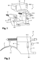
Figure 1 is an exploded perspective view of a surgical apparatus according to a first embodiment of the present invention. -
Figure 2 is a side view of the surgical apparatus offigure 1 . -
Figure 3 is a perspective view of the surgical apparatus offigure 1 . -
Figure 4 is a top view of a support frame of the surgical apparatus offigure 1 . -
Figure 5 is a perspective view of the support frame offigure 4 . -
Figure 6 is a perspective view of a cutting guide insert of the surgical apparatus offigure 1 . -
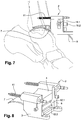
Figure 7 is a schematic view of the surgical apparatus offigure 1 secured to a tibia. -
Figure 8 is a perspective view of a surgical apparatus according to a second embodiment of the invention, secured to a tibia. -
Figures 1 to 7 represent asurgical apparatus 2 for cutting a tibia of a patient for the implantation of an ankle prosthesis. - The
surgical apparatus 2 comprises asupport frame 3 configured to be secured to the tibia of the patient, and a cuttingguide insert 4 movably mounted on thesupport frame 3 and configured to guide a cutting blade 5 (seefigure 7 ) for cutting of a lower end part of the tibia. Thesupport frame 3 and the cuttingguide insert 4 may for example be made in stainless steel, and thecutting blade 5 has advantageously a determined curvature. - As better shown on
figures 4 and5 , thesupport frame 3 includes amain body 6 forming a rear portion of thesupport frame 3 an configured to be secured to a front surface of the tibia of the patient, and atongue 7 forming an anterior portion of thesupport frame 3 and configured to bear on a tibial articular surface of a talus and to be supported by the tibial articular surface. - The
tongue 7 is curved and has substantially a saddle shape. Thetongue 7 particularly includes a lower concave surface 7.1 which is curved and configured to bear on the tibial articular surface of the talus, and an upper convex surface 7.2 which is curved and configured to cooperate with a lower end of the tibia. Advantageously, the lower concave surface 7.1 of thetongue 7 is at least partially complementary to the tibial articular surface of a talus, and the upper convex surface 7.2 of thetongue 7 is at least partially complementary to the lower end of a tibia, and for example to the tibial roof. Thetongue 7 may include an end part having for example a thickness of about 1 mm. - The
main body 6 includes an upwardlyopen housing 8 in which the cuttingguide insert 4 is inserted. Further, as shown onfigure 4 , themain body 6 comprises a curvedfront surface 9 configured to substantially face a front surface of the tibia and to bear against said front surface of the tibia when themain body 6 is secured to the tibia. Themain body 6 may for example have a substantially prismatic shape. - The
surgical apparatus 2 further includes one or several bone anchoring member(s) 11 configured to be anchored to a tibia and to secure themain body 6 to the tibia. According to the embodiment shown on the figures, thesurgical apparatus 2 includes twobone anchoring members 11 provided on themain body 6, for example on opposite side walls of themain body 6. The twobone anchoring members 11 may for example extend in a same plane and converge forwardly. Advantageously, eachbone anchoring member 11 is a bone anchoring pin. - As better shown on
figure 6 , the cuttingguide insert 4 includes a guidinggroove 12 configured to guide thecutting blade 5 along a main trajectory T so as to cut of a lower end part of the tibia The main trajectory T is advantageously substantially orthogonal to a longitudinal axis of the tibia when themain body 6 of thesupport frame 3 is secured to the tibia. - Advantageously, the guiding
groove 12 includes a curved guiding surface and defines the main trajectory T. Thecutting blade 5 is particularly adapted to be inserted in the guidinggroove 12 to follow the main trajectory T. - As the
main body 6, the cuttingguide insert 4 also includes a curvedfront surface 13 configured to substantially face the front surface of a tibia when themain body 6 is secured to the tibia and when the cuttingguide insert 4 is inserted in thehousing 8. - The cutting
guide insert 4 is movably mounted on themain body 6 along a displacement direction D so as to adjust a tibial cutting height. The displacement direction D extends substantially parallely to a longitudinal axis of a tibia when the rear portion of thesupport frame 3 is secured to the tibia. - According to the embodiment shown on the figures, the
surgical apparatus 2 includesgraduations 14 provided on thesupport frame 3, and for example on themain body 6, each graduation corresponding to a value of the tibial cutting height, and areading mark 15 associated with thegraduations 14 and provided on the cuttingguide insert 4. However, thegraduations 14 may also be provided on the cuttingguide insert 4 and the readingmark 15 may also be provided on thesupport frame 3. - Further, the
support frame 3 includes one or several immobilization member(s) 16 configured to immobilize the cuttingguide insert 4 on themain body 6. According to the embodiment shown on the figures, thesupport frame 3 includes a first immobilization member 16.1 provided on a side wall of themain body 6 and configured to immobilize the cuttingguide insert 4 on thesupport frame 3, and a second immobilization member 16.2 provided on a rear wall of themain body 6 and also configured to immobilize the cuttingguide insert 4 on thesupport frame 3. Each of the first and second immobilization members 16.1, 16.2 may be for example a pressure screw. - According to the embodiment shown on the figures, the
main body 6 includes a first elongated opening 17.1 provided on the side wall of themain body 6 and in which is slidably mounted the first immobilization member 16.1, and a second elongated opening 17.2 provided on the rear wall of themain body 6 and in which is slidably mounted the second immobilization member 16.2. Each of the first and second elongated openings 17.1, 17.2 extends advantageously substantially parallely to the displacement direction D. - According to the embodiment shown on the figures, the cutting
guide insert 4 further includes a first hole 18.1 provided on a side wall of the cuttingguide insert 4 and configured to partially receive an end portion of the first immobilization member 16.1, and a second hole 18.2 provided on a rear wall of the cuttingguide insert 4 and configured to partially receive an end portion of the second immobilization member 16.2. Each of the first and second holes 18.1, 18.2 may for example be elongated. - Advantageously, each of the first and second immobilization members 16.1, 16.2 is movable between a first configuration in which the cutting
guide insert 4 is displaceable with respect to thesupport frame 3 along the displacement direction D in order to adjust the tibial cutting height, and a second configuration in which said immobilization member is partially received in the respective hole provided on the cuttingguide insert 4 and immobilizes the cuttingguide insert 4 with respect to thesupport frame 3 in order to keep the adjusted tibial cutting height. - As shown on
figures 5 , themain body 6 of thesupport frame 3 may also include connectingelements 19 configured to accommodate removable coupling means provided for example on a support device. - According to an embodiment of the invention, the
cutting blade 5 may be provided in different sizes, and the cuttingguide insert 4 may also be provided in different sizes, each size of thecutting blade 5 and of the cuttingguide insert 4 corresponding to a size of a respective tibial prosthetic component. - According to another embodiment of the invention, the
support frame 3 may also be provided in different sizes, and theseveral support frames 3 advantageously comprisetongues 7 having different thicknesses. Thus, if, after having positioning atongue 7 of a selectedsupport frame 3 between the talus and the tibia of a patient, there is an excessive clearance between thetongue 7 and the bones of the ankle of the patient, the surgeon may replace the previously selectedsupport frame 3 with anothersupport frame 3 comprising atongue 7 having a higher thickness in order to limit or cancel said clearance. -
Figure 8 disclose asurgical apparatus 2 according to a second embodiment of the invention which differs from the first embodiment substantially in that the cuttingguide insert 4 includes two guiding grooves, and particularly a tibial guiding groove 12.1 configured to guide thecutting blade 5 for cutting a lower end part of the tibia of a patient, and a talus guiding groove 12.2 configured to guide thecutting blade 5 for cutting an upper end part of the talus of a patient. - Each of the tibial guiding groove 12.1 and the talus guiding groove 12.2 may have a determined curvature in order to guide a
curved cutting blade 5 and to perform curved cuts on the talus and the tibia. However, each of the tibial guiding groove 12.1 and the talus guiding groove 12.2 may be straight in order to guide astraight cutting blade 5 and to perform straight cuts on the talus and the tibia. Advantageously, the tibial guiding groove 12.1 and the talus guiding groove 12.2 extend substantially parallel to each other. - Of course, the invention is not restricted to the embodiments described above by way of non-limiting examples, but on the contrary it encompasses all embodiments thereof.
Claims (15)
- A surgical apparatus (2) for cutting a tibia of a patient for the implantation of an ankle prosthesis, the surgical apparatus (2) comprising:- a support frame (3) having an anterior portion configured to bear on an upper surface of a talus of the patient, and a rear portion configured to be secured to the tibia of the patient;- a cutting guide insert (4) mounted on the support frame (3) and configured to guide a cutting blade (5) for cutting of a lower end part of the tibia, the cutting guide insert (4) being movably mounted on the rear portion of the support frame (3) along a displacement direction (D) so as to adjust a tibial cutting height, characterized in that surgical apparatus further comprises:- graduations (14) provided on the support frame (3) or on the cutting guide insert (4), each graduation (14) corresponding to a value of the tibial cutting height; and- a reading mark (15) associated with the graduations (14) and provided on the cutting guide insert (4) or on support frame (3).
- The surgical apparatus (2) according to claim 1, wherein the cutting guide insert (4) is configured to guide the cutting blade (5) along a main trajectory (T).
- The surgical apparatus (2) according to claim 2, wherein the main trajectory (T) is transversal to a longitudinal axis of the tibia when the rear portion of the support frame (3) is secured to the tibia.
- The surgical apparatus (2) according to any one of claims 1 to 3, wherein the displacement direction (D) extends substantially parallely to a longitudinal axis of the tibia when the rear portion of the support frame (3) is secured to the tibia.
- The surgical apparatus (2) according to any of claims 1 to 4, wherein the support frame (3) includes at least one immobilization member (16.1, 16.2) configured to immobilize the cutting guide insert (4) on the support frame (3).
- The surgical apparatus (2) according to claim 5, wherein the at least one immobilization member (16.1, 16.2) is movable between at least a first configuration in which the cutting guide insert (4) is displaceable with respect to the support frame (3) along the displacement direction (D) in order to adjust the tibial cutting height, and a second configuration in which the at least one immobilization member (16.1, 16.2) immobilizes the cutting guide insert (4) with respect to the support frame (3) in order to keep the adjusted tibial cutting height.
- The surgical apparatus (2) according to any one of claims 1 to 6, wherein the support frame (3) comprises a main body (6) forming the rear portion, and a tongue (7) forming the anterior portion.
- The surgical apparatus (2) according to claim 7, wherein the tongue (7) includes a lower concave surface (7.1) configured to bear on the upper surface of the talus, and an upper convex surface (7.2) configured to cooperate with a lower end of the tibia.
- The surgical apparatus (2) according to claim 7 or 8, wherein the main body (6) of the support frame (3) includes a housing (8) in which the cutting guide insert (4) is inserted.
- The surgical apparatus (2) according to any one of claims 7 to 9, wherein the main body (6) of the support frame (3) further comprises a curved front surface (9) configured to substantially face a front surface of the tibia when the rear portion is secured to the tibia.
- The surgical apparatus (2) according to any one of claims 7 to 10 in combination with claim 5, wherein the support frame (3) includes a first immobilization member (16.1) and a second immobilization member (16.2) configured to immobilize the cutting guide insert (4) on the support frame (3), the first immobilization member (16.1) being provided on a side wall of the main body (6) and the second immobilization member (16.2) being provided on a rear wall of the main body (6).
- The surgical apparatus (2) according to any one of claims 1 to 11, further including at least one bone anchoring member (11) configured to be anchored to the tibia and to secure the rear portion of the support frame (3) to the tibia of the patient.
- The surgical apparatus (2) according to any one of claims 1 to 12, wherein the cutting guide insert (4) has at least one guiding groove (12) configured to guide the cutting blade (5).
- The surgical apparatus (2) according to claim 13, wherein the at least one guiding groove (12) defines a curved guiding surface.
- A surgical system including at least one surgical apparatus (2) according to any one of claims 1 to 14, and at least one cutting blade (5) configured to cut a lower end part of the tibia.
Priority Applications (1)
| Application Number | Priority Date | Filing Date | Title |
|---|---|---|---|
| PL18700538T PL3568091T3 (en) | 2017-01-16 | 2018-01-05 | A surgical apparatus for cutting a tibia of a patient for the implantation of an ankle prosthesis |
Applications Claiming Priority (2)
| Application Number | Priority Date | Filing Date | Title |
|---|---|---|---|
| IT102017000001219A IT201700001219A1 (en) | 2017-01-16 | 2017-01-16 | INTRA-ARTICULAR ALIGNMENT EQUIPMENT / INSTRUMENT TIBIO / TARSICA |
| PCT/EP2018/050233 WO2018130460A1 (en) | 2017-01-16 | 2018-01-05 | A surgical apparatus for cutting a tibia of a patient for the implantation of an ankle prosthesis |
Publications (2)
| Publication Number | Publication Date |
|---|---|
| EP3568091A1 EP3568091A1 (en) | 2019-11-20 |
| EP3568091B1 true EP3568091B1 (en) | 2021-03-31 |
Family
ID=59409604
Family Applications (1)
| Application Number | Title | Priority Date | Filing Date |
|---|---|---|---|
| EP18700538.4A Active EP3568091B1 (en) | 2017-01-16 | 2018-01-05 | A surgical apparatus for cutting a tibia of a patient for the implantation of an ankle prosthesis |
Country Status (5)
| Country | Link |
|---|---|
| US (1) | US11253275B2 (en) |
| EP (1) | EP3568091B1 (en) |
| IT (1) | IT201700001219A1 (en) |
| PL (1) | PL3568091T3 (en) |
| WO (1) | WO2018130460A1 (en) |
Families Citing this family (3)
| Publication number | Priority date | Publication date | Assignee | Title |
|---|---|---|---|---|
| US12108959B2 (en) | 2019-05-29 | 2024-10-08 | Wright Medical Technology, Inc. | Preparing a tibia for receiving tibial implant component of a replacement ankle |
| US12582421B2 (en) | 2022-05-13 | 2026-03-24 | Wright Medical Technology, Inc. | Intraoperative adjustable guides, systems, and methods |
| US12569355B2 (en) | 2023-08-31 | 2026-03-10 | Wright Medical Technology, Inc. | Systems and methods for total ankle arthroplasty |
Family Cites Families (12)
| Publication number | Priority date | Publication date | Assignee | Title |
|---|---|---|---|---|
| US6673116B2 (en) * | 1999-10-22 | 2004-01-06 | Mark A. Reiley | Intramedullary guidance systems and methods for installing ankle replacement prostheses |
| WO2006023824A2 (en) * | 2004-08-19 | 2006-03-02 | Kinetikos Medical Incorporated | Ankle prosthesis and method of curved resection |
| CA2601090C (en) * | 2005-03-14 | 2013-08-20 | Inbone Technologies, Inc. | Ankle replacement system |
| GB2445146C (en) * | 2006-12-23 | 2016-03-23 | Corin Ltd | Improvements in and relating to an ankle prosthesis |
| AU2009262113A1 (en) * | 2008-06-25 | 2009-12-30 | Small Bone Innovations, Inc. | Surgical instrumentation and methods of use for implanting a prothesis |
| US8545501B2 (en) * | 2008-10-22 | 2013-10-01 | Wright Medical Technology, Inc. | Instruments for preparing bone implants |
| US8808297B2 (en) * | 2009-02-24 | 2014-08-19 | Microport Orthopedics Holdings Inc. | Orthopedic surgical guide |
| US8337503B2 (en) * | 2009-04-13 | 2012-12-25 | George John Lian | Custom radiographically designed cutting guides and instruments for use in total ankle replacement surgery |
| DE102009031269B4 (en) * | 2009-06-30 | 2013-07-25 | Universität Rostock | Device for in-situ milling of articular surfaces |
| EP2849684B1 (en) * | 2012-05-08 | 2016-05-25 | Zimmer, Inc. | Instruments for foot and ankle fusion |
| WO2014020561A1 (en) * | 2012-08-01 | 2014-02-06 | Custom Med Orthopaedics Proprietary Limited | A surgical tool guide |
| WO2016201078A2 (en) * | 2015-06-09 | 2016-12-15 | Mohamed Mahfouz | Patient-specific instrumentation and methods for total ankle replacement |
-
2017
- 2017-01-16 IT IT102017000001219A patent/IT201700001219A1/en unknown
-
2018
- 2018-01-05 US US16/478,055 patent/US11253275B2/en active Active
- 2018-01-05 WO PCT/EP2018/050233 patent/WO2018130460A1/en not_active Ceased
- 2018-01-05 PL PL18700538T patent/PL3568091T3/en unknown
- 2018-01-05 EP EP18700538.4A patent/EP3568091B1/en active Active
Non-Patent Citations (1)
| Title |
|---|
| None * |
Also Published As
| Publication number | Publication date |
|---|---|
| US20190365394A1 (en) | 2019-12-05 |
| EP3568091A1 (en) | 2019-11-20 |
| PL3568091T3 (en) | 2022-02-07 |
| IT201700001219A1 (en) | 2018-07-16 |
| WO2018130460A1 (en) | 2018-07-19 |
| US11253275B2 (en) | 2022-02-22 |
Similar Documents
| Publication | Publication Date | Title |
|---|---|---|
| US11871943B2 (en) | Alignment instruments and methods for use in total ankle replacement | |
| EP2001373B1 (en) | Orthopaedic cutting guide instrument | |
| US5624444A (en) | Femoral resection instrumentation including three-dimensional jig and method of use | |
| US7621920B2 (en) | Adjustable cut guide | |
| US5702460A (en) | Revision femoral trial prosthesis | |
| EP2906129B1 (en) | Bone shortening device | |
| US5935128A (en) | Orthopaedic template system including a joint locator | |
| US11819278B2 (en) | Surgical kit for knee osteotomies and corresponding preoperative planning method | |
| US9028503B2 (en) | Drill guide | |
| JP2003513706A (en) | Knee prosthesis system | |
| CA2005847A1 (en) | Femoral surface shaping guide for knee implants | |
| US11253275B2 (en) | Surgical apparatus for cutting a tibia of a patient for the implantation of an ankle prosthesis | |
| WO1994000056A1 (en) | Sizing and cutting guide for resecting the distal end of the femur | |
| AU2009262113A1 (en) | Surgical instrumentation and methods of use for implanting a prothesis | |
| JP2022528939A (en) | Bone cutting guide | |
| JP2014515650A (en) | Guide tool for resection of patellofemoral joint | |
| ES2699088T3 (en) | Surgical aid device for the placement of an orthopedic implant between two bones of a patient's joint | |
| EP1414356B1 (en) | Guide for locating femur resection plane | |
| US20140171952A1 (en) | External Tibial Mill Guide and Method of Use | |
| KR102385661B1 (en) | Surgical device for surgery of the human knee | |
| KR20070015112A (en) | Mechanisms for insertion of intervertebral prostheses | |
| US20070073304A1 (en) | Femur alignment guide device | |
| US10682148B2 (en) | System for partially cutting a bone |
Legal Events
| Date | Code | Title | Description |
|---|---|---|---|
| STAA | Information on the status of an ep patent application or granted ep patent |
Free format text: STATUS: UNKNOWN |
|
| STAA | Information on the status of an ep patent application or granted ep patent |
Free format text: STATUS: THE INTERNATIONAL PUBLICATION HAS BEEN MADE |
|
| PUAI | Public reference made under article 153(3) epc to a published international application that has entered the european phase |
Free format text: ORIGINAL CODE: 0009012 |
|
| STAA | Information on the status of an ep patent application or granted ep patent |
Free format text: STATUS: REQUEST FOR EXAMINATION WAS MADE |
|
| 17P | Request for examination filed |
Effective date: 20190709 |
|
| AK | Designated contracting states |
Kind code of ref document: A1 Designated state(s): AL AT BE BG CH CY CZ DE DK EE ES FI FR GB GR HR HU IE IS IT LI LT LU LV MC MK MT NL NO PL PT RO RS SE SI SK SM TR |
|
| AX | Request for extension of the european patent |
Extension state: BA ME |
|
| DAV | Request for validation of the european patent (deleted) | ||
| DAX | Request for extension of the european patent (deleted) | ||
| GRAP | Despatch of communication of intention to grant a patent |
Free format text: ORIGINAL CODE: EPIDOSNIGR1 |
|
| STAA | Information on the status of an ep patent application or granted ep patent |
Free format text: STATUS: GRANT OF PATENT IS INTENDED |
|
| INTG | Intention to grant announced |
Effective date: 20201109 |
|
| RAP1 | Party data changed (applicant data changed or rights of an application transferred) |
Owner name: AIC DEVELOPMENT GBR Owner name: FH ORTHO Owner name: FOURNITURES HOSPITALIERES INDUSTRIE |
|
| GRAS | Grant fee paid |
Free format text: ORIGINAL CODE: EPIDOSNIGR3 |
|
| GRAA | (expected) grant |
Free format text: ORIGINAL CODE: 0009210 |
|
| STAA | Information on the status of an ep patent application or granted ep patent |
Free format text: STATUS: THE PATENT HAS BEEN GRANTED |
|
| AK | Designated contracting states |
Kind code of ref document: B1 Designated state(s): AL AT BE BG CH CY CZ DE DK EE ES FI FR GB GR HR HU IE IS IT LI LT LU LV MC MK MT NL NO PL PT RO RS SE SI SK SM TR |
|
| REG | Reference to a national code |
Ref country code: GB Ref legal event code: FG4D Ref country code: CH Ref legal event code: EP |
|
| REG | Reference to a national code |
Ref country code: AT Ref legal event code: REF Ref document number: 1376053 Country of ref document: AT Kind code of ref document: T Effective date: 20210415 |
|
| REG | Reference to a national code |
Ref country code: DE Ref legal event code: R096 Ref document number: 602018014701 Country of ref document: DE |
|
| REG | Reference to a national code |
Ref country code: IE Ref legal event code: FG4D |
|
| REG | Reference to a national code |
Ref country code: LT Ref legal event code: MG9D |
|
| PG25 | Lapsed in a contracting state [announced via postgrant information from national office to epo] |
Ref country code: HR Free format text: LAPSE BECAUSE OF FAILURE TO SUBMIT A TRANSLATION OF THE DESCRIPTION OR TO PAY THE FEE WITHIN THE PRESCRIBED TIME-LIMIT Effective date: 20210331 Ref country code: FI Free format text: LAPSE BECAUSE OF FAILURE TO SUBMIT A TRANSLATION OF THE DESCRIPTION OR TO PAY THE FEE WITHIN THE PRESCRIBED TIME-LIMIT Effective date: 20210331 Ref country code: BG Free format text: LAPSE BECAUSE OF FAILURE TO SUBMIT A TRANSLATION OF THE DESCRIPTION OR TO PAY THE FEE WITHIN THE PRESCRIBED TIME-LIMIT Effective date: 20210630 Ref country code: NO Free format text: LAPSE BECAUSE OF FAILURE TO SUBMIT A TRANSLATION OF THE DESCRIPTION OR TO PAY THE FEE WITHIN THE PRESCRIBED TIME-LIMIT Effective date: 20210630 |
|
| PG25 | Lapsed in a contracting state [announced via postgrant information from national office to epo] |
Ref country code: SE Free format text: LAPSE BECAUSE OF FAILURE TO SUBMIT A TRANSLATION OF THE DESCRIPTION OR TO PAY THE FEE WITHIN THE PRESCRIBED TIME-LIMIT Effective date: 20210331 Ref country code: LV Free format text: LAPSE BECAUSE OF FAILURE TO SUBMIT A TRANSLATION OF THE DESCRIPTION OR TO PAY THE FEE WITHIN THE PRESCRIBED TIME-LIMIT Effective date: 20210331 Ref country code: RS Free format text: LAPSE BECAUSE OF FAILURE TO SUBMIT A TRANSLATION OF THE DESCRIPTION OR TO PAY THE FEE WITHIN THE PRESCRIBED TIME-LIMIT Effective date: 20210331 |
|
| REG | Reference to a national code |
Ref country code: NL Ref legal event code: MP Effective date: 20210331 |
|
| REG | Reference to a national code |
Ref country code: AT Ref legal event code: MK05 Ref document number: 1376053 Country of ref document: AT Kind code of ref document: T Effective date: 20210331 |
|
| PG25 | Lapsed in a contracting state [announced via postgrant information from national office to epo] |
Ref country code: EE Free format text: LAPSE BECAUSE OF FAILURE TO SUBMIT A TRANSLATION OF THE DESCRIPTION OR TO PAY THE FEE WITHIN THE PRESCRIBED TIME-LIMIT Effective date: 20210331 Ref country code: CZ Free format text: LAPSE BECAUSE OF FAILURE TO SUBMIT A TRANSLATION OF THE DESCRIPTION OR TO PAY THE FEE WITHIN THE PRESCRIBED TIME-LIMIT Effective date: 20210331 Ref country code: LT Free format text: LAPSE BECAUSE OF FAILURE TO SUBMIT A TRANSLATION OF THE DESCRIPTION OR TO PAY THE FEE WITHIN THE PRESCRIBED TIME-LIMIT Effective date: 20210331 Ref country code: NL Free format text: LAPSE BECAUSE OF FAILURE TO SUBMIT A TRANSLATION OF THE DESCRIPTION OR TO PAY THE FEE WITHIN THE PRESCRIBED TIME-LIMIT Effective date: 20210331 Ref country code: SM Free format text: LAPSE BECAUSE OF FAILURE TO SUBMIT A TRANSLATION OF THE DESCRIPTION OR TO PAY THE FEE WITHIN THE PRESCRIBED TIME-LIMIT Effective date: 20210331 Ref country code: AT Free format text: LAPSE BECAUSE OF FAILURE TO SUBMIT A TRANSLATION OF THE DESCRIPTION OR TO PAY THE FEE WITHIN THE PRESCRIBED TIME-LIMIT Effective date: 20210331 |
|
| PG25 | Lapsed in a contracting state [announced via postgrant information from national office to epo] |
Ref country code: PT Free format text: LAPSE BECAUSE OF FAILURE TO SUBMIT A TRANSLATION OF THE DESCRIPTION OR TO PAY THE FEE WITHIN THE PRESCRIBED TIME-LIMIT Effective date: 20210802 Ref country code: RO Free format text: LAPSE BECAUSE OF FAILURE TO SUBMIT A TRANSLATION OF THE DESCRIPTION OR TO PAY THE FEE WITHIN THE PRESCRIBED TIME-LIMIT Effective date: 20210331 Ref country code: SK Free format text: LAPSE BECAUSE OF FAILURE TO SUBMIT A TRANSLATION OF THE DESCRIPTION OR TO PAY THE FEE WITHIN THE PRESCRIBED TIME-LIMIT Effective date: 20210331 Ref country code: IS Free format text: LAPSE BECAUSE OF FAILURE TO SUBMIT A TRANSLATION OF THE DESCRIPTION OR TO PAY THE FEE WITHIN THE PRESCRIBED TIME-LIMIT Effective date: 20210731 |
|
| REG | Reference to a national code |
Ref country code: DE Ref legal event code: R097 Ref document number: 602018014701 Country of ref document: DE |
|
| PG25 | Lapsed in a contracting state [announced via postgrant information from national office to epo] |
Ref country code: DK Free format text: LAPSE BECAUSE OF FAILURE TO SUBMIT A TRANSLATION OF THE DESCRIPTION OR TO PAY THE FEE WITHIN THE PRESCRIBED TIME-LIMIT Effective date: 20210331 Ref country code: AL Free format text: LAPSE BECAUSE OF FAILURE TO SUBMIT A TRANSLATION OF THE DESCRIPTION OR TO PAY THE FEE WITHIN THE PRESCRIBED TIME-LIMIT Effective date: 20210331 Ref country code: ES Free format text: LAPSE BECAUSE OF FAILURE TO SUBMIT A TRANSLATION OF THE DESCRIPTION OR TO PAY THE FEE WITHIN THE PRESCRIBED TIME-LIMIT Effective date: 20210331 |
|
| PLBE | No opposition filed within time limit |
Free format text: ORIGINAL CODE: 0009261 |
|
| STAA | Information on the status of an ep patent application or granted ep patent |
Free format text: STATUS: NO OPPOSITION FILED WITHIN TIME LIMIT |
|
| 26N | No opposition filed |
Effective date: 20220104 |
|
| PG25 | Lapsed in a contracting state [announced via postgrant information from national office to epo] |
Ref country code: IS Free format text: LAPSE BECAUSE OF FAILURE TO SUBMIT A TRANSLATION OF THE DESCRIPTION OR TO PAY THE FEE WITHIN THE PRESCRIBED TIME-LIMIT Effective date: 20210731 |
|
| PG25 | Lapsed in a contracting state [announced via postgrant information from national office to epo] |
Ref country code: MC Free format text: LAPSE BECAUSE OF FAILURE TO SUBMIT A TRANSLATION OF THE DESCRIPTION OR TO PAY THE FEE WITHIN THE PRESCRIBED TIME-LIMIT Effective date: 20210331 |
|
| REG | Reference to a national code |
Ref country code: BE Ref legal event code: MM Effective date: 20220131 |
|
| PG25 | Lapsed in a contracting state [announced via postgrant information from national office to epo] |
Ref country code: LU Free format text: LAPSE BECAUSE OF NON-PAYMENT OF DUE FEES Effective date: 20220105 |
|
| PG25 | Lapsed in a contracting state [announced via postgrant information from national office to epo] |
Ref country code: BE Free format text: LAPSE BECAUSE OF NON-PAYMENT OF DUE FEES Effective date: 20220131 |
|
| P01 | Opt-out of the competence of the unified patent court (upc) registered |
Effective date: 20230622 |
|
| PG25 | Lapsed in a contracting state [announced via postgrant information from national office to epo] |
Ref country code: MK Free format text: LAPSE BECAUSE OF FAILURE TO SUBMIT A TRANSLATION OF THE DESCRIPTION OR TO PAY THE FEE WITHIN THE PRESCRIBED TIME-LIMIT Effective date: 20210331 Ref country code: CY Free format text: LAPSE BECAUSE OF FAILURE TO SUBMIT A TRANSLATION OF THE DESCRIPTION OR TO PAY THE FEE WITHIN THE PRESCRIBED TIME-LIMIT Effective date: 20210331 |
|
| PG25 | Lapsed in a contracting state [announced via postgrant information from national office to epo] |
Ref country code: HU Free format text: LAPSE BECAUSE OF FAILURE TO SUBMIT A TRANSLATION OF THE DESCRIPTION OR TO PAY THE FEE WITHIN THE PRESCRIBED TIME-LIMIT; INVALID AB INITIO Effective date: 20180105 |
|
| PG25 | Lapsed in a contracting state [announced via postgrant information from national office to epo] |
Ref country code: TR Free format text: LAPSE BECAUSE OF FAILURE TO SUBMIT A TRANSLATION OF THE DESCRIPTION OR TO PAY THE FEE WITHIN THE PRESCRIBED TIME-LIMIT Effective date: 20210331 |
|
| PG25 | Lapsed in a contracting state [announced via postgrant information from national office to epo] |
Ref country code: MT Free format text: LAPSE BECAUSE OF FAILURE TO SUBMIT A TRANSLATION OF THE DESCRIPTION OR TO PAY THE FEE WITHIN THE PRESCRIBED TIME-LIMIT Effective date: 20210331 |
|
| PG25 | Lapsed in a contracting state [announced via postgrant information from national office to epo] |
Ref country code: GR Free format text: LAPSE BECAUSE OF NON-PAYMENT OF DUE FEES Effective date: 20210331 |
|
| PG25 | Lapsed in a contracting state [announced via postgrant information from national office to epo] |
Ref country code: GR Free format text: LAPSE BECAUSE OF NON-PAYMENT OF DUE FEES Effective date: 20210331 |
|
| PGFP | Annual fee paid to national office [announced via postgrant information from national office to epo] |
Ref country code: IE Payment date: 20250123 Year of fee payment: 8 |
|
| PGFP | Annual fee paid to national office [announced via postgrant information from national office to epo] |
Ref country code: GB Payment date: 20251230 Year of fee payment: 9 |
|
| PGFP | Annual fee paid to national office [announced via postgrant information from national office to epo] |
Ref country code: FR Payment date: 20251230 Year of fee payment: 9 |
|
| REG | Reference to a national code |
Ref country code: CH Ref legal event code: U11 Free format text: ST27 STATUS EVENT CODE: U-0-0-U10-U11 (AS PROVIDED BY THE NATIONAL OFFICE) Effective date: 20260201 |
|
| PGFP | Annual fee paid to national office [announced via postgrant information from national office to epo] |
Ref country code: DE Payment date: 20260115 Year of fee payment: 9 |
|
| PGFP | Annual fee paid to national office [announced via postgrant information from national office to epo] |
Ref country code: IT Payment date: 20260114 Year of fee payment: 9 |
|
| PGFP | Annual fee paid to national office [announced via postgrant information from national office to epo] |
Ref country code: CH Payment date: 20260201 Year of fee payment: 9 |
|
| PGFP | Annual fee paid to national office [announced via postgrant information from national office to epo] |
Ref country code: PL Payment date: 20260102 Year of fee payment: 9 |